JP4450256B2 - Droplet discharge head and droplet discharge apparatus - Google Patents
Droplet discharge head and droplet discharge apparatus Download PDFInfo
- Publication number
- JP4450256B2 JP4450256B2 JP2008171852A JP2008171852A JP4450256B2 JP 4450256 B2 JP4450256 B2 JP 4450256B2 JP 2008171852 A JP2008171852 A JP 2008171852A JP 2008171852 A JP2008171852 A JP 2008171852A JP 4450256 B2 JP4450256 B2 JP 4450256B2
- Authority
- JP
- Japan
- Prior art keywords
- bonding film
- substrate
- film
- head according
- bonding
- Prior art date
- Legal status (The legal status is an assumption and is not a legal conclusion. Google has not performed a legal analysis and makes no representation as to the accuracy of the status listed.)
- Expired - Fee Related
Links
Images


Description
本発明は、液滴吐出ヘッドおよび液滴吐出装置に関するものである。 The present invention relates to a droplet discharge head and a droplet discharge device.
例えば、インクジェットプリンタのような液滴吐出装置には、液滴を吐出するための液滴吐出ヘッドが備えられている。このような液滴吐出ヘッドとしては、例えば、インクを液滴として吐出するノズルに連通し、インクを収容するインク室(キャビティ)と、このインク室の壁面を変形させる駆動用の圧電素子とを備えるものが知られている。
このような液滴吐出ヘッドにあっては、駆動用の圧電素子を伸縮させることにより、インク室の一部(振動板)を変位させる。これにより、インク室の容積を変化させて、ノズルからインク液滴が吐出される。
For example, a droplet discharge device such as an ink jet printer is provided with a droplet discharge head for discharging droplets. As such a droplet discharge head, for example, an ink chamber (cavity) that communicates with a nozzle that discharges ink as droplets and stores ink, and a piezoelectric element for driving that deforms the wall surface of the ink chamber are provided. What you have is known.
In such a droplet discharge head, a part of the ink chamber (vibrating plate) is displaced by expanding and contracting the driving piezoelectric element. Thereby, the volume of the ink chamber is changed and ink droplets are ejected from the nozzles.
ところで、このような液滴吐出ヘッドは、ノズルが形成されたノズルプレートと、インク室を画成する基板との間を、感光性接着剤または弾性接着剤で接着することによって組み立てられている(例えば、特許文献1参照)。
しかしながら、ノズルプレートと基板との間に接着剤を供給する際に、接着剤の供給量を厳密に制御することは極めて困難である。このため、供給する接着剤の量を均一にすることができず、ノズルプレートと基板との距離が不均一になる。これにより、液滴吐出ヘッド内に複数個設けられたインク室のそれぞれの容積が不均一になったり、液滴吐出ヘッド毎でインク室の容積が不均一になってしまう。また、液滴吐出ヘッドと印刷用紙等の印字媒体との間の距離が不均一になる。さらに、接合箇所から接着剤がはみ出してしまうおそれがある。このような問題により、液滴吐出ヘッドの寸法精度が低下し、インクジェットプリンタの印字の品位が低下することとなる。
また、接着剤は、インク室に貯留されたインクに長期間曝される。このように接着剤がインクに曝されると、インク中の有機成分によって、接着剤に変質・劣化が生じる。このため、インク室の液密性が低下したり、接着剤中の成分がインクに溶出したりするおそれがある。
By the way, such a droplet discharge head is assembled by bonding a nozzle plate in which nozzles are formed and a substrate that defines an ink chamber with a photosensitive adhesive or an elastic adhesive ( For example, see Patent Document 1).
However, when supplying the adhesive between the nozzle plate and the substrate, it is extremely difficult to strictly control the supply amount of the adhesive. For this reason, the amount of the adhesive to be supplied cannot be made uniform, and the distance between the nozzle plate and the substrate becomes non-uniform. As a result, the volumes of the plurality of ink chambers provided in the droplet discharge heads become non-uniform, or the volumes of the ink chambers become non-uniform for each droplet discharge head. Further, the distance between the droplet discharge head and the print medium such as print paper becomes non-uniform. Furthermore, there is a possibility that the adhesive protrudes from the joint location. Due to such a problem, the dimensional accuracy of the droplet discharge head is lowered, and the printing quality of the ink jet printer is lowered.
Further, the adhesive is exposed to ink stored in the ink chamber for a long time. When the adhesive is exposed to the ink in this manner, the adhesive is altered or deteriorated by the organic component in the ink. For this reason, there is a possibility that the liquid tightness of the ink chamber may be lowered, or components in the adhesive may be eluted into the ink.
一方、液滴吐出ヘッドを構成する各部を、固体接合法によって接合する方法も知られている。
固体接合は、接着剤等の接着層を介在させることなく、部材同士を直接接合する方法であり、例えば、シリコン直接接合法、陽極接合法等の方法が知られている。
ところが、固体接合には、
・接合可能な部材の材質が限られる
・接合プロセスにおいて高温(例えば、700〜800℃程度)での熱処理を伴う
・接合プロセスにおける雰囲気が減圧雰囲気に限られる
・一部の領域を部分的に接合することができない
といった問題がある。
On the other hand, there is also known a method of joining the respective parts constituting the droplet discharge head by a solid joining method.
Solid bonding is a method in which members are directly bonded without interposing an adhesive layer such as an adhesive. For example, methods such as a silicon direct bonding method and an anodic bonding method are known.
However, for solid bonding,
・ Materials of members that can be joined are limited. ・ The joining process involves heat treatment at a high temperature (for example, about 700 to 800.degree. C.). ・ The atmosphere in the joining process is limited to a reduced pressure atmosphere. There is a problem that can not be done.
本発明の目的は、寸法精度および耐薬品性に優れ、長期間にわたって高品位の印字が可能な信頼性の高い液滴吐出ヘッド、および、かかる液滴吐出ヘッドを備えた信頼性の高い液滴吐出装置を提供することにある。 An object of the present invention is to provide a highly reliable droplet discharge head that is excellent in dimensional accuracy and chemical resistance, and capable of high-quality printing over a long period of time, and a highly reliable droplet having such a droplet discharge head It is to provide a discharge device.
このような目的は、下記の本発明により達成される。
本発明の液滴吐出ヘッドは、基板と、
前記基板の一方の面に設けられ、吐出液を液滴として吐出するノズル孔を備えるノズルプレートと、
前記基板の他方の面に設けられた封止板と、を有し、
前記基板と前記ノズルプレートと前記封止板とで、前記吐出液を貯留する吐出液貯留室が形成され、
前記基板と前記ノズルプレートとが接合膜を介して接合されており、
前記接合膜は、プラズマ重合により形成されたものであり、シロキサン(Si−O)結合を有するSi骨格と、該Si骨格に結合する脱離基と、Si−H結合とを含み、
前記接合膜にエネルギーを付与したことにより、前記接合膜の表面に存在する前記脱離基が前記Si骨格から脱離し、前記接合膜の表面に発現した接着性によって、前記接合膜は、前記基板と前記ノズルプレートとを接合していることを特徴とする。
これにより、寸法精度および耐薬品性に優れ、長期間にわたって高品位の印字が可能な信頼性の高い液滴吐出ヘッドが得られる。また、プラズマ重合法により形成された接合膜は緻密で均質なものとなる。そして、基板とノズルプレートとを特に強固に接合し得るものとなる。さらに、プラズマ重合法で作製された接合膜は、エネルギーが付与されて活性化された状態が比較的長時間にわたって維持される。このため、液滴吐出ヘッドの製造過程の簡素化、効率化を図ることができる。
また、Si−H結合は、シロキサン結合の生成が規則的に行われるのを阻害すると考えられる。このため、シロキサン結合は、Si−H結合を避けるように形成されることとなり、Si骨格の規則性が低下する。このようにして、接合膜中にSi−H結合が含まれることにより、結晶化度の低いSi骨格を効率よく形成することができる。
Such an object is achieved by the present invention described below.
Droplet discharge head of the present invention includes a base plate,
Provided on one surface of the pre-Symbol substrate, a nozzle plate having nozzle holes for ejecting ejection exudates as droplets,
Anda sealing plate provided on the other surface of the front Stories substrate,
A discharge liquid storage chamber for storing the discharge liquid is formed by the substrate, the nozzle plate, and the sealing plate,
The substrate and the nozzle plate are bonded via a bonding film,
The bonding film has been more formed in the plasma Polymerization includes an Si skeleton which have a siloxane (Si-O) bond, and the leaving group bonded to the Si skeleton, the Si-H bonds,
By the application of energy to the bonding film, wherein the leaving groups present on the front surface of the bonding film is desorbed from the Si skeleton, the adhesion was expressed in the table surface of the bonding film, the bonding film, The substrate and the nozzle plate are joined.
As a result, a highly reliable droplet discharge head that has excellent dimensional accuracy and chemical resistance and can perform high-quality printing over a long period of time can be obtained. Further, the bonding film formed by the plasma polymerization method becomes dense and homogeneous. And a board | substrate and a nozzle plate can be joined especially firmly. Furthermore, the bonding film manufactured by the plasma polymerization method is maintained in an activated state by applying energy for a relatively long time. For this reason, it is possible to simplify and improve the efficiency of the manufacturing process of the droplet discharge head.
Further, it is considered that the Si—H bond inhibits the generation of siloxane bond regularly. For this reason, the siloxane bond is formed so as to avoid the Si—H bond, and the regularity of the Si skeleton is lowered. In this manner, the Si skeleton having a low degree of crystallinity can be efficiently formed by including Si—H bonds in the bonding film.
本発明の液滴吐出ヘッドでは、前記接合膜を構成する全原子からH原子を除いた原子のうち、Si原子の含有率とO原子の含有率の合計が、10〜90原子%であることが好ましい。
これにより、接合膜は、Si原子とO原子とが強固なネットワークを形成し、接合膜自体がより強固なものとなる。このため、接合膜は、基板およびノズルプレートに対して、特に高い接合強度を示すものとなる。
In the liquid droplet ejection head according to the present invention, the total of the Si atom content and the O atom content is 10 to 90 atomic% among atoms obtained by removing H atoms from all atoms constituting the bonding film. Is preferred.
Thus, in the bonding film, Si atoms and O atoms form a strong network, and the bonding film itself becomes stronger. For this reason, the bonding film exhibits particularly high bonding strength with respect to the substrate and the nozzle plate.
本発明の液滴吐出ヘッドでは、前記接合膜中のSi原子とO原子の存在比は、3:7〜7:3であることが好ましい。
これにより、接合膜の安定性が高くなり、基板とノズルプレートとをより強固に接合することができるようになる。
本発明の液滴吐出ヘッドでは、前記Si骨格は、シロキサン結合を含み、ランダムな原子配置を有することが好ましい。
本発明の液滴吐出ヘッドでは、前記Si骨格の結晶化度は、45%以下であることが好ましい。
これにより、Si骨格は十分にランダムな原子構造を含むものとなる。このため、Si骨格の特性が顕在化し、接合膜の寸法精度および接着性がより優れたものとなる。
In the liquid droplet ejection head of the present invention, the abundance ratio of Si atoms and O atoms in the bonding film is preferably 3: 7 to 7: 3.
Thereby, the stability of the bonding film is increased, and the substrate and the nozzle plate can be bonded more firmly.
In the liquid droplet ejection head according to the aspect of the invention, it is preferable that the Si skeleton includes a siloxane bond and has a random atomic arrangement.
In the droplet discharge head of the present invention, the crystallinity of the Si skeleton is preferably 45% or less.
As a result, the Si skeleton includes a sufficiently random atomic structure. For this reason, the characteristics of the Si skeleton become obvious, and the dimensional accuracy and adhesiveness of the bonding film become more excellent.
本発明の液滴吐出ヘッドでは、前記Si−H結合を含む接合膜についての赤外光吸収スペクトルにおいて、シロキサン結合に帰属するピーク強度を1としたとき、Si−H結合に帰属するピーク強度が0.001〜0.2であることが好ましい。
これにより、接合膜中の原子構造は、相対的に最もランダムなものとなる。このため、接合膜は、接合強度、耐薬品性および寸法精度において特に優れたものとなる。
In the droplet discharge head of the present invention, when the peak intensity attributed to the siloxane bond is 1, the peak intensity attributed to the Si—H bond is 1 in the infrared absorption spectrum of the bonding film including the Si—H bond. It is preferable that it is 0.001-0.2.
As a result, the atomic structure in the bonding film becomes relatively random. For this reason, the bonding film is particularly excellent in bonding strength, chemical resistance and dimensional accuracy.
本発明の液滴吐出ヘッドでは、前記脱離基は、H原子、B原子、C原子、N原子、O原子、P原子、S原子およびハロゲン系原子、またはこれらの各原子が前記Si骨格に結合するよう配置された原子団からなる群から選択される少なくとも1種で構成されたものであることが好ましい。
これらの脱離基は、エネルギーの付与による結合/脱離の選択性に比較的優れている。このため、このような脱離基は、接合膜の接着性をより高度なものとすることができる。
In the droplet discharge head of the present invention, the leaving group is an H atom, a B atom, a C atom, an N atom, an O atom, a P atom, an S atom, and a halogen atom, or each of these atoms in the Si skeleton. It is preferably composed of at least one selected from the group consisting of atomic groups arranged to be bonded.
These leaving groups are relatively excellent in binding / leaving selectivity by applying energy. For this reason, such a leaving group can make the adhesiveness of the bonding film higher.
本発明の液滴吐出ヘッドでは、前記脱離基は、アルキル基であることが好ましい。
アルキル基は化学的な安定性が高いため、脱離基としてアルキル基を含む接合膜は、耐候性および耐薬品性に優れたものとなる。
本発明の液滴吐出ヘッドでは、前記脱離基としてメチル基を含む接合膜についての赤外光吸収スペクトルにおいて、シロキサン結合に帰属するピーク強度を1としたとき、メチル基に帰属するピーク強度が0.05〜0.45であることが好ましい。
これにより、メチル基の含有率が最適化され、メチル基がシロキサン結合の生成を必要以上に阻害するのを防止しつつ、接合膜中に必要かつ十分な数の活性手が生じるため、接合膜に十分な接着性が生じる。また、接合膜には、メチル基に起因する十分な耐候性および耐薬品性が発現する。
In the droplet discharge head of the present invention, the leaving group is preferably an alkyl group.
Since the alkyl group has high chemical stability, the bonding film containing the alkyl group as a leaving group is excellent in weather resistance and chemical resistance.
In the droplet discharge head of the present invention, when the peak intensity attributed to the siloxane bond is 1 in the infrared absorption spectrum of the bonding film containing a methyl group as the leaving group, the peak intensity attributed to the methyl group is It is preferable that it is 0.05-0.45.
As a result, the content ratio of the methyl group is optimized, and a necessary and sufficient number of active hands are generated in the bonding film while preventing the methyl group from unnecessarily inhibiting the formation of the siloxane bond. Adhesiveness is sufficient. Further, the bonding film exhibits sufficient weather resistance and chemical resistance due to the methyl group.
本発明の液滴吐出ヘッドでは、前記接合膜は、ポリオルガノシロキサンを主材料として構成されていることが好ましい。
これにより、接合膜自体が優れた機械的特性を有するものとなる。また、多くの材料に対して特に優れた接着性を示す接合膜が得られる。したがって、この接合膜により、基板とノズルプレートとをより強固に接合することができる。また、非接着性と接着性との制御を容易かつ確実に行える接合膜となる。さらに、接合膜が優れた撥液性を示すため、耐久性に優れた信頼性の高いヘッドが得られる。
In the liquid droplet ejection head according to the aspect of the invention, it is preferable that the bonding film is made of polyorganosiloxane as a main material.
As a result, the bonding film itself has excellent mechanical properties. In addition, a bonding film exhibiting particularly excellent adhesion to many materials can be obtained. Therefore, the substrate and the nozzle plate can be more firmly bonded by this bonding film. Further, the bonding film can easily and reliably control the non-adhesiveness and the adhesiveness. Furthermore, since the bonding film exhibits excellent liquid repellency, a highly reliable head with excellent durability can be obtained.
本発明の液滴吐出ヘッドでは、前記ポリオルガノシロキサンは、オクタメチルトリシロキサンの重合物を主成分とするものであることが好ましい。
これにより、接着性に特に優れる接合膜が得られる。
本発明の液滴吐出ヘッドでは、前記プラズマ重合法において、プラズマを発生させる際の高周波の出力密度は、0.01〜100W/cm2であることが好ましい。
これにより、高周波の出力密度が高過ぎて原料ガスに必要以上のプラズマエネルギーが付加されるのを防止しつつ、ランダムな原子構造を有するSi骨格を確実に形成することができる。
本発明の液滴吐出ヘッドでは、前記接合膜の平均厚さは、1〜1000nmであることが好ましい。
これにより、基板とノズルプレートとの間の寸法精度が著しく低下するのを防止しつつ、これらをより強固に接合することができる。
In the droplet discharge head of the present invention, it is preferable that the polyorganosiloxane is mainly composed of a polymer of octamethyltrisiloxane.
Thereby, a bonding film having particularly excellent adhesiveness can be obtained.
In the droplet discharge head of the present invention, in the plasma polymerization method, it is preferable that a high frequency output density when generating plasma is 0.01 to 100 W / cm 2 .
Accordingly, it is possible to reliably form a Si skeleton having a random atomic structure while preventing the plasma gas from being added to the source gas more than necessary due to the high frequency power density.
In the liquid droplet ejection head according to the aspect of the invention, it is preferable that an average thickness of the bonding film is 1 to 1000 nm.
Thereby, these can be joined more firmly, preventing that the dimensional accuracy between a board | substrate and a nozzle plate falls remarkably.
本発明の液滴吐出ヘッドでは、前記接合膜は、流動性を有しない固体状のものであることが好ましい。
これにより、従来に比べて寸法精度が格段に高いヘッドが得られる。また、接着剤の硬化に要する時間が不要になるため、短時間で強固な接合が可能となる。
本発明の液滴吐出ヘッドでは、前記基板は、シリコン材料またはステンレス鋼を主材料として構成されていることが好ましい。
これらの材料は、耐薬品性に優れることから、長時間にわたって吐出液に曝されたとしても、基板またはノズルプレートが変質・劣化するのを確実に防止することができる。また、これらの材料は、加工性に優れるため、寸法精度の高い基板が得られる。このため、吐出液貯留室の容積の精度が高くなり、高品位の印字が可能な液滴吐出ヘッドが得られる。
In the liquid droplet ejection head according to the aspect of the invention, it is preferable that the bonding film is a solid having no fluidity.
As a result, a head having a remarkably high dimensional accuracy as compared with the prior art can be obtained. Further, since the time required for curing the adhesive is not required, strong bonding can be achieved in a short time.
In the liquid droplet ejection head according to the aspect of the invention, it is preferable that the substrate is composed mainly of a silicon material or stainless steel.
Since these materials are excellent in chemical resistance, even if they are exposed to the discharge liquid for a long time, it is possible to reliably prevent the substrate or nozzle plate from being altered or deteriorated. Moreover, since these materials are excellent in workability, a substrate with high dimensional accuracy can be obtained. For this reason, the accuracy of the volume of the discharge liquid storage chamber is increased, and a droplet discharge head capable of high-quality printing is obtained.
本発明の液滴吐出ヘッドでは、前記ノズルプレートは、シリコン材料またはステンレス鋼を主材料として構成されていることが好ましい。
これらの材料は、耐薬品性に優れることから、長時間にわたって吐出液に曝されたとしても、ノズルプレートが変質・劣化するのを確実に防止することができる。また、これらの材料は、加工性に優れるため、寸法精度の高いノズルプレートが得られる。
In the droplet discharge head of the present invention, it is preferable that the nozzle plate is composed mainly of a silicon material or stainless steel.
Since these materials are excellent in chemical resistance, it is possible to reliably prevent the nozzle plate from being altered or deteriorated even when exposed to the discharge liquid for a long time. Moreover, since these materials are excellent in workability, a nozzle plate with high dimensional accuracy can be obtained.
本発明の液滴吐出ヘッドでは、前記基板の前記接合膜と接している面には、あらかじめ、前記接合膜との密着性を高める表面処理が施されていることが好ましい。
これにより、基板と接合膜との間の接合強度をより高めることができ、ひいては、基板とノズルプレートとの接合強度を高めることができる。
本発明の液滴吐出ヘッドでは、前記ノズルプレートの前記接合膜と接している面には、あらかじめ、前記接合膜との密着性を高める表面処理が施されていることが好ましい。
これにより、ノズルプレートと接合膜との間の接合強度をより高めることができ、ひいては、基板とノズルプレートとの接合強度を高めることができる。
In the liquid droplet ejection head according to the aspect of the invention, it is preferable that a surface of the substrate that is in contact with the bonding film is previously subjected to a surface treatment that improves adhesion with the bonding film.
Thereby, the bonding strength between the substrate and the bonding film can be further increased, and as a result, the bonding strength between the substrate and the nozzle plate can be increased.
In the droplet discharge head of the present invention, it is preferable that the surface of the nozzle plate that is in contact with the bonding film is previously subjected to a surface treatment that improves adhesion to the bonding film.
As a result, the bonding strength between the nozzle plate and the bonding film can be further increased, and as a result, the bonding strength between the substrate and the nozzle plate can be increased.
本発明の液滴吐出ヘッドでは、前記表面処理は、プラズマ処理であることが好ましい。
これにより、接合膜を形成するために、基板またはノズルプレートの表面を特に最適化することができる。
本発明の液滴吐出ヘッドでは、前記基板と前記接合膜との間に、中間層を有することが好ましい。
これにより、前記基板と前記接合膜との間の接合強度を高め、信頼性の高い液滴吐出ヘッドを得ることができる。
In the liquid droplet ejection head according to the aspect of the invention, it is preferable that the surface treatment is a plasma treatment.
Thereby, in order to form the bonding film, the surface of the substrate or the nozzle plate can be particularly optimized.
In the droplet discharge head of the present invention, it is preferable that an intermediate layer is provided between the substrate and the bonding film.
Thereby, the bonding strength between the substrate and the bonding film can be increased, and a highly reliable droplet discharge head can be obtained.
本発明の液滴吐出ヘッドでは、前記ノズルプレートと前記接合膜との間に、中間層を有することが好ましい。
これにより、前記ノズルプレートと前記接合膜との間の接合強度を高め、信頼性の高い液滴吐出ヘッドを得ることができる。
本発明の液滴吐出ヘッドでは、前記中間層は、酸化物系材料を主材料として構成されていることが好ましい。
これにより、基板と接合膜との間、および、ノズルプレートと接合膜との間において、それぞれ接合強度を高めることができる。
In the liquid droplet ejection head of the present invention, it is preferable that an intermediate layer is provided between the nozzle plate and the bonding film.
As a result, the bonding strength between the nozzle plate and the bonding film can be increased, and a highly reliable droplet discharge head can be obtained.
In the liquid droplet ejection head according to the aspect of the invention, it is preferable that the intermediate layer is composed mainly of an oxide-based material.
As a result, the bonding strength can be increased between the substrate and the bonding film and between the nozzle plate and the bonding film.
本発明の液滴吐出ヘッドでは、前記エネルギーの付与は、前記接合膜にエネルギー線を照射する方法、前記接合膜を加熱する方法、および、前記接合膜に圧縮力を付与する方法のうちの少なくとも1つの方法により行われることが好ましい。
これにより、接合膜に対して比較的簡単に効率よくエネルギーを付与することができる。
In the liquid droplet ejection head according to the aspect of the invention, the energy may be applied by at least one of a method of irradiating the bonding film with energy rays, a method of heating the bonding film, and a method of applying a compressive force to the bonding film. It is preferably carried out by one method.
Thereby, energy can be imparted to the bonding film relatively easily and efficiently.
本発明の液滴吐出ヘッドでは、前記エネルギー線は、波長150〜300nmの紫外線であることが好ましい。
これにより、付与されるエネルギー量が最適化されるので、接合膜中のSi骨格が必要以上に破壊されるのを防止しつつ、Si骨格と脱離基との間の結合を選択的に切断することができる。これにより、接合膜の特性(機械的特性、化学的特性等)が低下するのを防止しつつ、接合膜に接着性を発現させることができる。
In the liquid droplet ejection head according to the aspect of the invention, it is preferable that the energy ray is an ultraviolet ray having a wavelength of 150 to 300 nm.
As a result, the amount of energy applied is optimized, and the bond between the Si skeleton and the leaving group is selectively cut while preventing the Si skeleton in the bonding film from being destroyed more than necessary. can do. Thereby, adhesiveness can be expressed in the bonding film while preventing the characteristics (mechanical characteristics, chemical characteristics, etc.) of the bonding film from deteriorating.
本発明の液滴吐出ヘッドでは、前記加熱の温度は、25〜100℃であることが好ましい。
これにより、基板またはノズルプレート等が熱によって変質・劣化するのを確実に防止しつつ、接合膜を確実に活性化させることができる。
本発明の液滴吐出ヘッドでは、前記圧縮力は、0.2〜10MPaであることが好ましい。
これにより、基板またはノズルプレートに損傷等が生じるのを避けつつ、単に圧縮するのみで、接合膜に十分な接着性を発現させることができる。
In the droplet discharge head of the present invention, the heating temperature is preferably 25 to 100 ° C.
Thereby, it is possible to reliably activate the bonding film while reliably preventing the substrate, the nozzle plate, or the like from being altered or deteriorated by heat.
In the droplet discharge head of the present invention, the compressive force is preferably 0.2 to 10 MPa.
As a result, sufficient adhesiveness can be exhibited in the bonding film by simply compressing the substrate or nozzle plate while avoiding damage or the like.
本発明の液滴吐出ヘッドでは、前記基板と前記封止板とが、前記接合膜と同様の接合膜を介して接合されていることが好ましい。
これにより、基板と封止板との密着性が高くなり、吐出液貯留室の液密性を特に高めることができる。
本発明の液滴吐出ヘッドでは、前記封止板は、複数の層を積層してなる積層体で構成されており、
前記積層体中の層のうち、隣接する少なくとも1組の層の層間が、前記接合膜と同様の接合膜を介して接合されていることが好ましい。
これにより、層間の密着性および歪みの伝搬性が高くなる。このため、振動手段による歪みを吐出液貯留室内の圧力変化に確実に変換することができる。すなわち、封止板の変位のレスポンスを高めることができる。
In the liquid droplet ejection head according to the aspect of the invention, it is preferable that the substrate and the sealing plate are bonded via a bonding film similar to the bonding film.
Thereby, the adhesiveness of a board | substrate and a sealing plate becomes high, and can improve especially the liquid-tightness of a discharge liquid storage chamber.
In the liquid droplet ejection head of the present invention, the sealing plate is composed of a laminate formed by laminating a plurality of layers,
Of the layers in the laminate, it is preferable that at least one pair of adjacent layers is bonded via a bonding film similar to the bonding film.
Thereby, the adhesiveness between layers and the propagation property of strain are enhanced. For this reason, the distortion by the vibration means can be reliably converted into a pressure change in the discharge liquid storage chamber. That is, the response of the displacement of the sealing plate can be enhanced.
本発明の液滴吐出ヘッドでは、当該液滴吐出ヘッドは、さらに、前記封止板の前記基板と反対側に設けられ、前記封止板を振動させる振動手段を有し、
前記封止板と前記振動手段とが、前記接合膜と同様の接合膜を介して接合されていることが好ましい。
これにより、封止板と振動手段との間の密着性および歪みの伝搬性が高くなる。その結果、振動手段による歪みを吐出液貯留室内の圧力変化に確実に変換することができる。
In the liquid droplet ejection head of the present invention, the liquid droplet ejection head is further provided on the opposite side of the sealing plate from the substrate, and has vibration means for vibrating the sealing plate,
It is preferable that the sealing plate and the vibration unit are bonded via a bonding film similar to the bonding film.
Thereby, the adhesiveness between the sealing plate and the vibration means and the distortion propagation property are enhanced. As a result, the distortion caused by the vibration means can be reliably converted into a pressure change in the discharge liquid storage chamber.
本発明の液滴吐出ヘッドでは、前記振動手段は、圧電素子で構成されていることが好ましい。
これにより、封止板に発生する撓みの程度を容易に制御することができる。これにより、インク滴の大きさを容易に制御することができる。
本発明の液滴吐出ヘッドでは、当該液滴吐出ヘッドは、さらに、前記封止板の前記基板と反対側に設けられたケースヘッドを有し、
前記封止板と前記ケースヘッドとが、前記接合膜と同様の接合膜を介して接合されていることが好ましい。
これにより、封止板とケースヘッドとの密着性が高くなる。その結果、ケースヘッドによって、封止板を確実に支持し、封止板、基板およびノズルプレートのよじれや反り等を確実に防止することができる。
本発明の液滴吐出装置は、本発明の液滴吐出ヘッドを備えることを特徴とする。
これにより、信頼性の高い液滴吐出装置が得られる。
In the liquid droplet ejection head according to the aspect of the invention, it is preferable that the vibration unit includes a piezoelectric element.
Thereby, the degree of bending generated in the sealing plate can be easily controlled. Thereby, the size of the ink droplets can be easily controlled.
In the droplet discharge head of the present invention, the droplet discharge head further includes a case head provided on the opposite side of the sealing plate from the substrate,
It is preferable that the sealing plate and the case head are bonded via a bonding film similar to the bonding film.
Thereby, the adhesiveness of a sealing board and a case head becomes high. As a result, the case head can reliably support the sealing plate and reliably prevent the sealing plate, the substrate and the nozzle plate from being twisted or warped.
The liquid droplet ejection apparatus of the present invention includes the liquid droplet ejection head of the present invention.
Thereby, a highly reliable droplet discharge device can be obtained.
以下、本発明の液滴吐出ヘッドおよび液滴吐出装置を、添付図面に示す好適実施形態に基づいて詳細に説明する。
<インクジェット式記録ヘッド>
≪第1実施形態≫
まず、本発明の液滴吐出ヘッドをインクジェット式記録ヘッドに適用した場合の第1実施形態について説明する。
Hereinafter, a droplet discharge head and a droplet discharge apparatus of the present invention will be described in detail based on preferred embodiments shown in the accompanying drawings.
<Inkjet recording head>
<< First Embodiment >>
First, a first embodiment in which the droplet discharge head of the present invention is applied to an ink jet recording head will be described.
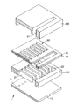
図1は、本発明の液滴吐出ヘッドをインクジェット式記録ヘッドに適用した場合の第1実施形態を示す分解斜視図、図2は、図1に示すインクジェット式記録ヘッドの断面図、図3は、図1に示すインクジェット式記録ヘッドを備えるインクジェットプリンタの実施形態を示す概略図である。なお、以下の説明では、図1および図2中の上側を「上」、下側を「下」と言う。 FIG. 1 is an exploded perspective view showing a first embodiment when the droplet discharge head of the present invention is applied to an ink jet recording head, FIG. 2 is a sectional view of the ink jet recording head shown in FIG. 1, and FIG. FIG. 2 is a schematic view showing an embodiment of an ink jet printer including the ink jet recording head shown in FIG. 1. In the following description, the upper side in FIGS. 1 and 2 is referred to as “upper” and the lower side is referred to as “lower”.
図1に示すインクジェット式記録ヘッド1(以下、単に「ヘッド1」という。)は、図3に示すようなインクジェットプリンタ(本発明の液滴吐出装置)9に搭載されている。
図3に示すインクジェットプリンタ9は、装置本体92を備えており、上部後方に記録用紙Pを設置するトレイ921と、下部前方に記録用紙Pを排出する排紙口922と、上部面に操作パネル97とが設けられている。
An ink jet recording head 1 (hereinafter, simply referred to as “
The
操作パネル97は、例えば、液晶ディスプレイ、有機ELディスプレイ、LEDランプ等で構成され、エラーメッセージ等を表示する表示部(図示せず)と、各種スイッチ等で構成される操作部(図示せず)とを備えている。
また、装置本体92の内部には、主に、往復動するヘッドユニット93を備える印刷装置(印刷手段)94と、記録用紙Pを1枚ずつ印刷装置94に送り込む給紙装置(給紙手段)95と、印刷装置94および給紙装置95を制御する制御部(制御手段)96とを有している。
The
Further, inside the apparatus
制御部96の制御により、給紙装置95は、記録用紙Pを一枚ずつ間欠送りする。この記録用紙Pは、ヘッドユニット93の下部近傍を通過する。このとき、ヘッドユニット93が記録用紙Pの送り方向とほぼ直交する方向に往復移動して、記録用紙Pへの印刷が行なわれる。すなわち、ヘッドユニット93の往復動と記録用紙Pの間欠送りとが、印刷における主走査および副走査となって、インクジェット方式の印刷が行なわれる。
Under the control of the control unit 96, the
印刷装置94は、ヘッドユニット93と、ヘッドユニット93の駆動源となるキャリッジモータ941と、キャリッジモータ941の回転を受けて、ヘッドユニット93を往復動させる往復動機構942とを備えている。
ヘッドユニット93は、その下部に、多数のノズル孔11を備えるヘッド1と、ヘッド1にインクを供給するインクカートリッジ931と、ヘッド1およびインクカートリッジ931を搭載したキャリッジ932とを有している。
The
The
なお、インクカートリッジ931として、イエロー、シアン、マゼンタ、ブラック(黒)の4色のインクを充填したものを用いることにより、フルカラー印刷が可能となる。
往復動機構942は、その両端をフレーム(図示せず)に支持されたキャリッジガイド軸943と、キャリッジガイド軸943と平行に延在するタイミングベルト944とを有している。
The
キャリッジ932は、キャリッジガイド軸943に往復動自在に支持されるとともに、タイミングベルト944の一部に固定されている。
キャリッジモータ941の作動により、プーリを介してタイミングベルト944を正逆走行させると、キャリッジガイド軸943に案内されて、ヘッドユニット93が往復動する。そして、この往復動の際に、ヘッド1から適宜インクが吐出され、記録用紙Pへの印刷が行われる。
The
When the
給紙装置95は、その駆動源となる給紙モータ951と、給紙モータ951の作動により回転する給紙ローラ952とを有している。
給紙ローラ952は、記録用紙Pの送り経路(記録用紙P)を挟んで上下に対向する従動ローラ952aと駆動ローラ952bとで構成され、駆動ローラ952bは給紙モータ951に連結されている。これにより、給紙ローラ952は、トレイ921に設置した多数枚の記録用紙Pを、印刷装置94に向かって1枚ずつ送り込めるようになっている。なお、トレイ921に代えて、記録用紙Pを収容する給紙カセットを着脱自在に装着し得るような構成であってもよい。
The
The
制御部96は、例えばパーソナルコンピュータやディジタルカメラ等のホストコンピュータから入力された印刷データに基づいて、印刷装置94や給紙装置95等を制御することにより印刷を行うものである。
制御部96は、いずれも図示しないが、主に、各部を制御する制御プログラム等を記憶するメモリ、印刷装置94(キャリッジモータ941)を駆動する駆動回路、給紙装置95(給紙モータ951)を駆動する駆動回路、および、ホストコンピュータからの印刷データを入手する通信回路と、これらに電気的に接続され、各部での各種制御を行うCPUとを備えている。
The control unit 96 performs printing by controlling the
Although not shown, the control unit 96 mainly includes a memory that stores a control program for controlling each unit, a drive circuit that drives the printing device 94 (carriage motor 941), and a paper feeding device 95 (paper feeding motor 951). Drive circuit, a communication circuit for obtaining print data from a host computer, and a CPU that is electrically connected to these and performs various controls in each unit.
また、CPUには、例えば、インクカートリッジ931のインク残量、ヘッドユニット93の位置等を検出可能な各種センサ等が、それぞれ電気的に接続されている。
制御部96は、通信回路を介して、印刷データを入手してメモリに格納する。CPUは、この印刷データを処理して、この処理データおよび各種センサからの入力データに基づいて、各駆動回路に駆動信号を出力する。この駆動信号により印刷装置94および給紙装置95は、それぞれ作動する。これにより、記録用紙Pに印刷が行われる。
Further, for example, various sensors that can detect the remaining ink amount of the
The control unit 96 obtains print data via the communication circuit and stores it in the memory. The CPU processes the print data and outputs a drive signal to each drive circuit based on the process data and input data from various sensors. The
以下、ヘッド1について、図1および図2を参照しつつ詳述する。
図1および図2に示すように、ヘッド1は、ノズルプレート10と、吐出液貯留室形成基板(基板)20と、封止シート30と、封止シート30上に設けられた振動板40と、振動板40上に設けられた圧電素子(振動手段)50およびケースヘッド60とを有する。また、本実施形態では、封止シート30と振動板40との積層体により、封止板を構成している。なお、このヘッド1は、ピエゾジェット式ヘッドを構成する。
Hereinafter, the
As shown in FIGS. 1 and 2, the
吐出液貯留室形成基板20(以下、省略して「基板20」と言う。)には、インクを貯留する複数の吐出液貯留室(圧力室)21と、各吐出液貯留室21に連通し、各吐出液貯留室21にインクを供給する吐出液供給室22とが形成されている。
図1および図2に示すように、各吐出液貯留室21および吐出液供給室22は、それぞれ、平面視において、ほぼ長方形状をなし、各吐出液貯留室21の幅(短辺)は、吐出液供給室22の幅(短辺)より細幅となっている。
A discharge liquid storage chamber forming substrate 20 (hereinafter referred to as “
As shown in FIGS. 1 and 2, each of the discharge
また、各吐出液貯留室21は、吐出液供給室22に対して、ほぼ垂直をなすように配置されており、各吐出液貯留室21および吐出液供給室22は、平面視において全体として、櫛状をなしている。
なお、吐出液供給室22は、平面視において、本実施形態のように長方形状のものの他、例えば、台形状、三角形状または俵形状(カプセル形状)のものであってもよい。
In addition, each discharge
In addition, the discharge
基板20を構成する材料としては、例えば、単結晶シリコン、多結晶シリコン、アモルファスシリコンのようなシリコン材料、ステンレス鋼、チタン、アルミニウムのような金属材料、石英ガラス、ケイ酸ガラス(石英ガラス)、ケイ酸アルカリガラス、ソーダ石灰ガラス、カリ石灰ガラス、鉛(アルカリ)ガラス、バリウムガラス、ホウケイ酸ガラスのようなガラス材料、アルミナ、ジルコニア、フェライト、窒化ケイ素、窒化アルミニウム、窒化ホウ素、窒化チタン、炭化ケイ素、炭化ホウ素、炭化チタン、炭化タングステンのようなセラミックス材料、グラファイトのような炭素材料、ポリエチレン、ポリプロピレン、エチレン−プロピレン共重合体、エチレン−酢酸ビニル共重合体(EVA)等のポリオレフィン、環状ポリオレフィン、変性ポリオレフィン、ポリ塩化ビニル、ポリ塩化ビニリデン、ポリスチレン、ポリアミド、ポリイミド、ポリアミドイミド、ポリカーボネート、ポリ−(4−メチルペンテン−1)、アイオノマー、アクリル系樹脂、ポリメチルメタクリレート、アクリロニトリル−ブタジエン−スチレン共重合体(ABS樹脂)、アクリロニトリル−スチレン共重合体(AS樹脂)、ブタジエン−スチレン共重合体、ポリオキシメチレン、ポリビニルアルコール(PVA)、エチレン−ビニルアルコール共重合体(EVOH)、ポリエチレンテレフタレート(PET)、ポリエチレンナフタレート、ポリブチレンテレフタレート(PBT)、ポリシクロヘキサンテレフタレート(PCT)等のポリエステル、ポリエーテル、ポリエーテルケトン(PEK)、ポリエーテルエーテルケトン(PEEK)、ポリエーテルイミド、ポリアセタール(POM)、ポリフェニレンオキシド、変性ポリフェニレンオキシド、変性ポリフェニレンエーテル樹脂(PBO)、ポリサルフォン、ポリエーテルサルフォン、ポリフェニレンサルファイド(PPS)、ポリアリレート、芳香族ポリエステル(液晶ポリマー)、ポリテトラフルオロエチレン、ポリフッ化ビニリデン、その他フッ素系樹脂、スチレン系、ポリオレフィン系、ポリ塩化ビニル系、ポリウレタン系、ポリエステル系、ポリアミド系、ポリブタジエン系、トランスポリイソプレン系、フッ素ゴム系、塩素化ポリエチレン系等の各種熱可塑性エラストマー、エポキシ樹脂、フェノール樹脂、ユリア樹脂、メラミン樹脂、アラミド系樹脂、不飽和ポリエステル、シリコーン樹脂、ポリウレタン等、またはこれらを主とする共重合体、ブレンド体、ポリマーアロイ等の樹脂材料、またはこれらの各材料の1種または2種以上を組み合わせた複合材料等が挙げられる。 Examples of the material constituting the substrate 20 include silicon materials such as single crystal silicon, polycrystalline silicon, and amorphous silicon, metal materials such as stainless steel, titanium, and aluminum, quartz glass, silicate glass (quartz glass), Glass materials such as alkali silicate glass, soda lime glass, potash lime glass, lead (alkali) glass, barium glass, borosilicate glass, alumina, zirconia, ferrite, silicon nitride, aluminum nitride, boron nitride, titanium nitride, carbonized Ceramic materials such as silicon, boron carbide, titanium carbide, tungsten carbide, carbon materials such as graphite, polyolefins such as polyethylene, polypropylene, ethylene-propylene copolymer, ethylene-vinyl acetate copolymer (EVA), cyclic polyolefin , Modified polyolefin, polyvinyl chloride, polyvinylidene chloride, polystyrene, polyamide, polyimide, polyamideimide, polycarbonate, poly- (4-methylpentene-1), ionomer, acrylic resin, polymethyl methacrylate, acrylonitrile-butadiene-styrene Polymer (ABS resin), acrylonitrile-styrene copolymer (AS resin), butadiene-styrene copolymer, polyoxymethylene, polyvinyl alcohol (PVA), ethylene-vinyl alcohol copolymer (EVOH), polyethylene terephthalate (PET) ), Polyethylene naphthalate, polybutylene terephthalate (PBT), polycyclohexane terephthalate (PCT) and other polyesters, polyethers, polyether ketones (PEK) , Polyether ether ketone (PEEK), polyether imide, polyacetal (POM), polyphenylene oxide, modified polyphenylene oxide, modified polyphenylene ether resin (PBO), polysulfone, polyether sulfone, polyphenylene sulfide (PPS), polyarylate, fragrance Group polyester (liquid crystal polymer), polytetrafluoroethylene, polyvinylidene fluoride, other fluorine resins, styrene, polyolefin, polyvinyl chloride, polyurethane, polyester, polyamide, polybutadiene, trans polyisoprene, fluorine Various thermoplastic elastomers such as rubber and chlorinated polyethylene, epoxy resin, phenol resin, urea resin, melamine resin, aramid resin, unsaturated poly Examples thereof include ester, silicone resin, polyurethane and the like, or resin materials such as copolymers, blends and polymer alloys mainly composed of these, or composite materials obtained by combining one or more of these materials.
また、上記のような材料に、酸化処理(酸化膜形成)、めっき処理、不働態化処理、窒化処理等の各処理を施した材料でもよい。
これらの中でも、基板20の構成材料は、シリコン材料またはステンレス鋼であるのが好ましい。このような材料は、耐薬品性に優れることから、長時間にわたってインクに曝されたとしても、基板20が変質・劣化するのを確実に防止することができる。また、これらの材料は、加工性に優れるため、寸法精度の高い基板20が得られる。このため、吐出液貯留室21や吐出液供給室22の容積の精度が高くなり、高品位の印字が可能なヘッド1が得られる。
Moreover, the material which gave each process, such as an oxidation process (oxide film formation), a plating process, a passivation process, a nitriding process, to the above materials may be used.
Among these, the constituent material of the
また、吐出液供給室22は、後述するケースヘッド60に設けられた吐出液供給路61と連通して複数の吐出液貯留室21にインクを供給する共通のインク室として機能するリザーバ70の一部を構成する。
また、吐出液貯留室21と吐出液供給室22との内面に、あらかじめ、親水処理を施しておいてもよい。これにより、吐出液貯留室21および吐出液供給室22に貯留されたインク中に気泡が含まれるのを防止することができる。
Further, the discharge
Further, the inner surfaces of the discharge
また、基板20の下面(封止シート30と反対側の面)には、接合膜15を介して、ノズルプレート10が接合(接着)されている。
本発明の液滴吐出ヘッドは、この接合膜15、および、接合膜15を用いて基板20とノズルプレート10とを接合する方法に特徴を有するものである。
この接合膜15は、シロキサン(Si−O)結合を含みランダムな原子構造を有するSi骨格と、このSi骨格に結合する脱離基とを含むものである。
そして、この接合膜15は、エネルギーを付与したことにより、脱離基がSi骨格から脱離し、接合膜15の表面に発現した接着性によって、基板20とノズルプレート10とを接合している。
なお、接合膜15については、後に詳述する。
The
The droplet discharge head of the present invention is characterized by the
The
The
The
ノズルプレート10には、各吐出液貯留室21に対応するように、それぞれノズル孔11が形成(穿設)されている。このノズル孔11に、吐出液貯留室21に貯留されたインクを押し出させることにより、インクを液滴として吐出することができる。
また、ノズルプレート10は、各吐出液貯留室21や吐出液供給室22の内壁面の下面を構成している。すなわち、ノズルプレート10と、基板20および封止シート30とにより、各吐出液貯留室21や吐出液供給室22を画成している。
Nozzle holes 11 are formed (perforated) in the
Further, the
このようなノズルプレート10を構成する材料としては、例えば、前述したようなシリコン材料、金属材料、ガラス材料、セラミックス材料、炭素材料、樹脂材料、またはこれらの各材料の1種または2種以上を組み合わせた複合材料等が挙げられる。
これらの中でも、ノズルプレート10の構成材料は、シリコン材料またはステンレス鋼であるのが好ましい。このような材料は、耐薬品性に優れることから、長時間にわたってインクに曝されたとしても、ノズルプレート10が変質・劣化するのを確実に防止することができる。また、これらの材料は、加工性に優れるため、寸法精度の高いノズルプレート10が得られる。このため、信頼性の高いヘッド1が得られる。
Examples of the material constituting the
Among these, it is preferable that the constituent material of the
なお、ノズルプレート10の構成材料は、線膨張係数が300℃以下で2.5〜4.5[×10-6/℃]程度であるものが好ましい。
また、ノズルプレート10の厚さは、特に限定されないが、0.01〜1mm程度であるのが好ましい。
また、ノズルプレート10の下面には、必要に応じて、撥液膜(図示せず)が設けられる。これにより、ノズル孔から吐出されるインク滴が意図しない方向に吐出されるのを防止することができる。
The constituent material of the
The thickness of the
Further, a liquid repellent film (not shown) is provided on the lower surface of the
このような撥液膜の構成材料としては、例えば、撥液性を示す官能基を有するカップリング剤や、撥液性の樹脂材料等が挙げられる。
カップリング剤としては、例えば、シラン系カップリング剤、チタン系カップリング剤、アルミニウム系カップリング剤、ジルコニウム系カップリング剤、有機リン酸系カップリング剤、シリルパーオキサイド系カップリング剤等を用いることができる。
撥液性を示す官能基としては、例えば、フルオロアルキル基、アルキル基、ビニル基、エポキシ基、スチリル基、メタクリロキシ基等が挙げられる。
Examples of the constituent material of the liquid repellent film include a coupling agent having a functional group exhibiting liquid repellency, a liquid repellant resin material, and the like.
As the coupling agent, for example, a silane coupling agent, a titanium coupling agent, an aluminum coupling agent, a zirconium coupling agent, an organic phosphate coupling agent, a silyl peroxide coupling agent, or the like is used. be able to.
Examples of the functional group exhibiting liquid repellency include a fluoroalkyl group, an alkyl group, a vinyl group, an epoxy group, a styryl group, and a methacryloxy group.
一方、撥液性の樹脂材料としては、例えば、ポリテトラフルオロエチレン(PTFE)、テトラフルオロエチレン−パーフルオロアルキルビニルエーテル共重合体(PFA)、エチレン−テトラフルオロエチレン共重合体(ETFE)、パーフルオロエチレン−プロペン共重合体(FEP)、エチレン−クロロトリフルオロエチレン共重合体(ECTFE)のようなフッ素系樹脂等が挙げられる。 On the other hand, examples of liquid repellent resin materials include polytetrafluoroethylene (PTFE), tetrafluoroethylene-perfluoroalkyl vinyl ether copolymer (PFA), ethylene-tetrafluoroethylene copolymer (ETFE), and perfluoro. Examples thereof include fluorine-based resins such as ethylene-propene copolymer (FEP) and ethylene-chlorotrifluoroethylene copolymer (ECTFE).
一方、基板20の上面には、接合膜25を介して、封止シート30が接合(接着)されている。
また、封止シート30は、各吐出液貯留室21や吐出液供給室22の内壁面の上面を構成している。すなわち、封止シート30と、基板20およびノズルプレート10とにより、各吐出液貯留室21や吐出液供給室22を画成している。そして、封止シート30が基板20と確実に接合されていることにより、各吐出液貯留室21や吐出液供給室22の液密性を確保している。
On the other hand, the sealing
Further, the sealing
封止シート30を構成する材料としては、例えば、前述したようなシリコン材料、金属材料、ガラス材料、セラミックス材料、炭素材料、樹脂材料、またはこれらの各材料の1種または2種以上を組み合わせた複合材料等が挙げられる。
これらの中でも、封止シート30の構成材料は、ポリフェニレンサルファイド(PPS)、アラミド樹脂のような樹脂材料、シリコン材料またはステンレス鋼であるのが好ましい。このような材料は、耐薬品性に優れることから、長時間にわたってインクに曝されたとしても、封止シート30が変質・劣化するのを確実に防止することができる。このため、吐出液貯留室21内および吐出液供給室22内に、長期間にわたってインクを貯留することができる。
As a material constituting the sealing
Among these, the constituent material of the sealing
このような封止シート30と基板20とを接合する接合膜25は、基板20と封止シート30とを接合または接着し得るものであれば、いかなる材料で構成されていてもよく、基板20や封止シート30の各構成材料によって適宜選択されるが、例えば、エポキシ系接着剤、シリコーン系接着剤、ウレタン系接着剤のような接着剤、半田、ろう材等が挙げられる。
The
また、接合膜25は必ずしも設けられていなくてもよく、省略してもよい。この場合、基板20と封止シート30との間は、融着(溶接)、または、シリコン直接接合、陽極接合のような固体接合等の直接接合法によって接合(接着)することができる。
本実施形態では、接合膜25が前述の接合膜15と同じ接合機能(接着性)を有するものとする。
Further, the
In the present embodiment, it is assumed that the
すなわち、接合膜25は、シロキサン(Si−O)結合を含みランダムな原子構造を有するSi骨格と、このSi骨格に結合する脱離基とを含むものである。
そして、接合膜25は、エネルギーを付与したことにより、脱離基がSi骨格から脱離し、接合膜25の表面に発現した接着性によって、基板20と封止シート30とを接合している。
That is, the
The
なお、接合膜25については、前述した接合膜15とともに、後に詳述する。
封止シート30の上面には、接合膜35を介して、振動板40が接合(接着)されている。
振動板40を構成する材料としては、例えば、前述したようなシリコン材料、金属材料、ガラス材料、セラミックス材料、炭素材料、樹脂材料、またはこれらの各材料の1種または2種以上を組み合わせた複合材料等が挙げられる。そして、振動板40が封止シート30と確実に接合されていることにより、圧電素子50に発生した歪みを、封止シート30の変位、すなわち各吐出液貯留室21の容積変化に確実に変換している。
The
The
As a material constituting the
これらの中でも、振動板40の構成材料は、シリコン材料またはステンレス鋼であるのが好ましい。このような材料は、高速で弾性変形することが可能である。このため、圧電素子50が振動板40を変位させることによって、吐出液貯留室21の容積を高速に変化させることができる。その結果、インクを高精度に吐出することができる。
このような振動板40と封止シート30とを接合する接合膜35は、封止シート30と振動板40とを接合または接着し得るものであれば、いかなる材料で構成されていてもよく、封止シート30や振動板40の各構成材料によって適宜選択されるが、例えば、エポキシ系接着剤、シリコーン系接着剤、ウレタン系接着剤のような接着剤、半田、ろう材等が挙げられる。
Among these, it is preferable that the constituent material of the
The
また、接合膜35は必ずしも設けられていなくてもよく、省略してもよい。この場合、封止シート30と振動板40との間は、融着(溶接)、または、シリコン直接接合、陽極接合のような固体接合等の直接接合法によって接合(接着)することができる。
本実施形態では、接合膜35が前述の接合膜15と同じ接合機能(接着性)を有するものとする。
The
In the present embodiment, it is assumed that the
すなわち、接合膜35は、シロキサン(Si−O)結合を含みランダムな原子構造を有するSi骨格と、このSi骨格に結合する脱離基とを含むものである。
そして、接合膜35は、エネルギーを付与したことにより、脱離基がSi骨格から脱離し、接合膜35の表面に発現した接着性によって、封止シート30と振動板40とを接合している。
That is, the
The
なお、接合膜35については、前述した接合膜15および接合膜25とともに、後に詳述する。
また、本実施形態では、封止シート30と振動板40とを積層してなる積層体により封止板を構成しているが、この封止板は、1層であってもよく、3層以上の層が積層してなる積層体で構成されていてもよい。
The
Moreover, in this embodiment, although the sealing board is comprised by the laminated body formed by laminating | stacking the sealing
なお、3層以上の層が積層してなる積層体によって封止板が構成されている場合、積層体中の層のうち、隣接する少なくとも1組の層間が接合膜35で接合されたものであれば、積層体の寸法精度が高くなり、ひいては、ヘッド1の寸法精度を高めることができる。
振動板40の上面の一部(図2では、振動板40の上面の中央部付近)に、接合膜45aを介して、圧電素子(振動手段)50が接合(接着)されている。
In the case where the sealing plate is constituted by a laminate in which three or more layers are laminated, at least one pair of adjacent layers among the layers in the laminate is joined by the
A piezoelectric element (vibrating means) 50 is bonded (adhered) to a part of the upper surface of the diaphragm 40 (in FIG. 2, near the center of the upper surface of the diaphragm 40) via a
圧電素子50は、圧電材料で構成された圧電体層51と、この圧電体層51に電圧を印加する電極膜52との積層体で構成されている。このような圧電素子50では、電極膜52を介して圧電体層51に電圧を印加することにより、圧電体層51に電圧に応じた歪みが発生する(逆圧電効果)。この歪みが振動板40および封止シート30に撓み(振動)をもたらし、吐出液貯留室21の容積を変化させる。このように、圧電素子50が振動板40と確実に接合されていることにより、圧電素子50に発生した歪みを、振動板40および封止シート30の変位、ひいては、各吐出液貯留室21の容積変化へと確実に変換することができる。
The
また、圧電体層51と電極膜52との積層方向は、特に限定されず、振動板40に対して平行な方向であっても、直交する方向であってもよい。なお、圧電体層51と電極膜52との積層方向が、振動板40に対して直交する方向である場合、このように配置された圧電素子50を特にMLP(Multi Layer Piezo)と言う。圧電素子50がMLPであれば、振動板40の変位量を大きくとることができるので、インクの吐出量の調整幅が大きいという利点がある。
In addition, the stacking direction of the
圧電素子50のうち、接合膜45aに隣接する(接触する)面は、圧電素子50の配置方法によって異なるが、圧電体層が露出した面、電極膜が露出した面、または圧電体層と電極膜の双方が露出した面のいずれかである。
圧電素子50のうち、圧電体層51を構成する材料としては、例えば、チタン酸バリウム、ジルコン酸鉛、チタン酸ジルコン酸鉛、酸化亜鉛、窒化アルミニウム、タンタル酸リチウム、ニオブ酸リチウム、水晶等が挙げられる。
The surface of the
As a material constituting the
一方、電極膜52を構成する材料としては、例えば、Fe、Ni、Co、Zn、Pt、Au、Ag、Cu、Pd、Al、W、Ti、Mo、またはこれらを含む合金等の各種金属材料が挙げられる。
このような圧電素子50と振動板40とを接合する接合膜45aは、振動板40と圧電素子50とを接合または接着し得るものであれば、いかなる材料で構成されていてもよく、振動板40や圧電素子50の各構成材料によって適宜選択されるが、例えば、エポキシ系接着剤、シリコーン系接着剤、ウレタン系接着剤のような接着剤、半田、ろう材等が挙げられる。
On the other hand, as a material constituting the
The
また、接合膜45aは必ずしも設けられていなくてもよく、省略してもよい。この場合、振動板40と圧電素子50との間は、融着(溶接)、または、シリコン直接接合、陽極接合のような固体接合等の直接接合法によって接合(接着)することができる。
本実施形態では、接合膜45aが前述の接合膜15と同じ接合機能(接着性)を有するものとする。
Further, the
In the present embodiment, it is assumed that the
すなわち、接合膜45aは、シロキサン(Si−O)結合を含みランダムな原子構造を有するSi骨格と、このSi骨格に結合する脱離基とを含むものである。
そして、接合膜45aは、エネルギーを付与したことにより、脱離基がSi骨格から脱離し、接合膜45aの表面に発現した接着性によって、振動板40と圧電素子50とを接合している。
That is, the
The
なお、接合膜45aについては、前述した接合膜15、接合膜25および接合膜35とともに、後に詳述する。
ここで、前述した振動板40は、圧電素子50に対応する位置を取り囲むように環状に形成された凹部53を有している。すなわち、圧電素子50に対応する位置では、振動板40の一部が、この環状の凹部53を隔てて島状に孤立している。
The
Here, the
なお、接合膜45aは、環状の凹部53の内側に設けられている。
また、圧電素子50の電極膜52は、図示しない駆動ICと電気的に接続されている。これにより、駆動素子50の動作を駆動ICによって制御することができる。
また、振動板40の上面の一部には、接合膜45bを介して、ケースヘッド60が接合(接着)されている。このように、ケースヘッド60が振動板40と確実に接合されていることにより、ノズルプレート10、基板20、封止シート30および振動板40の積層体で構成された、いわゆるキャビティ部分を補強し、キャビティ部分のよじれや反り等を確実に抑制することができる。
Note that the
The
Further, the
ケースヘッド60を構成する材料としては、例えば、前述したようなシリコン材料、金属材料、ガラス材料、セラミックス材料、炭素材料、樹脂材料、またはこれらの各材料の1種または2種以上を組み合わせた複合材料等が挙げられる。
これらの中でも、ケースヘッド60の構成材料は、ポリフェニレンサルファイド(PPS)、ザイロンのような変性ポリフェニレンエーテル樹脂(「ザイロン」は登録商標)またはステンレス鋼であるのが好ましい。これらの材料は、十分な剛性を備えていることから、ヘッド1を支持するケースヘッド60の構成材料として好適である。
Examples of the material constituting the
Among these, the constituent material of the
このようなケースヘッド60と振動板40とを接合する接合膜45bは、振動板40とケースヘッド60とを接合または接着し得るものであれば、いかなる材料で構成されていてもよく、振動板40やケースヘッド60の各構成材料によって適宜選択されるが、例えば、エポキシ系接着剤、シリコーン系接着剤、ウレタン系接着剤のような接着剤、半田、ろう材等が挙げられる。
The
また、接合膜45bは必ずしも設けられていなくてもよく、省略してもよい。この場合、振動板40とケースヘッド60との間は、融着(溶接)、または、シリコン直接接合、陽極接合のような固体接合等の直接接合法によって接合(接着)することができる。
本実施形態では、接合膜45bが前述の接合膜15と同じ接合機能(接着性)を有するものとする。
Further, the
In the present embodiment, the
すなわち、接合膜45bは、シロキサン(Si−O)結合を含みランダムな原子構造を有するSi骨格と、このSi骨格に結合する脱離基とを含むものである。
そして、接合膜45bは、エネルギーを付与したことにより、脱離基がSi骨格から脱離し、接合膜45bの表面に発現した接着性によって、振動板40とケースヘッド60とを接合している。
That is, the
The
なお、接合膜45bについては、前述した接合膜15、接合膜25、接合膜35および接合膜45aとともに、後に詳述する。
また、接合膜25、封止シート30、接合膜35、振動板40および接合膜45bは、吐出液供給室22に対応する位置に貫通孔23を有する。この貫通孔23により、ケースヘッド60に設けられた吐出液供給路61と吐出液供給室22とが連通している。なお、吐出液供給路61と吐出液供給室22とにより、複数の吐出液貯留室21にインクを供給する共通のインク室として機能するリザーバ70の一部を構成する。
The
Further, the
このようなヘッド1では、図示しない外部吐出液供給手段からインクを取り込み、リザーバ70からノズル孔11に至るまで内部をインクで満たした後、駆動ICからの記録信号により、各吐出液貯留室21に対応するそれぞれの圧電素子50を動作させる。これにより、圧電素子50の逆圧電効果によって振動板40および封止シート30に撓み(振動)が生じる。その結果、例えば、各吐出液貯留室21内の容積が収縮すると、各吐出液貯留室21内の圧力が瞬間的に高まり、ノズル孔11からインクが液滴として押し出される(吐出される)。
In such a
このようにして、ヘッド1において、印刷したい位置の圧電素子50に、駆動ICを介して電圧を印加すること、すなわち、吐出信号を順次入力することにより、任意の文字が図形等を印刷することができる。
なお、ヘッド1は、前述したような構成のものに限らず、例えば、振動手段として圧電素子50をヒータで代替した構成(サーマル方式)のヘッドであってもよい。このようなヘッドは、ヒータでインクを加熱して沸騰させ、それによって吐出液貯留室内の圧力を高めることにより、インクをノズル孔11から液滴として吐出するよう構成されているものである。
さらに、振動手段のその他の例としては、静電アクチュエータ方式等が挙げられる。
なお、本実施形態のように、振動手段が圧電素子で構成されていることにより、振動板40および封止シート30に発生する撓みの程度を容易に制御することができる。これにより、インク滴の大きさを容易に制御することができる。
In this way, in the
The
Furthermore, other examples of the vibration means include an electrostatic actuator system.
Note that, as in the present embodiment, since the vibration means is configured by a piezoelectric element, the degree of bending generated in the
次に、接合膜15、接合膜25、接合膜35、接合膜45aおよび接合膜45bに共通して用いられる接合膜について説明する。なお、以下では、基板20上に形成された接合膜15を代表に説明する。
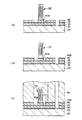
接合膜15のエネルギーを付与する前の状態は、プラズマ重合法により形成されたものであり、図4に示すように、シロキサン(Si−O)結合302を含み、ランダムな原子構造を有するSi骨格301と、このSi骨格301に結合する脱離基303とを含むものである。
Next, the bonding film used in common for the
The state before applying the energy of the
そして、この接合膜15にエネルギーを付与すると、図5に示すように、一部の脱離基303がSi骨格301から脱離し、代わりに活性手304が生じる。これにより、接合膜15の表面に接着性が発現する。このようにして接着性が発現した接合膜15により、基板20とノズルプレート10とが接合されている。
このような接合膜15は、シロキサン結合302を含みランダムな原子構造を有するSi骨格301の影響によって、変形し難い強固な膜となる。これは、Si骨格301の結晶性が低くなるため、結晶粒界における転位やズレ等の欠陥が生じ難いためであると考えられる。このため、基板20とノズルプレート10との間の距離を高い寸法精度で一定に保持することができ、各吐出液貯留室21や吐出液供給室22の各容積を厳密に制御することができる。その結果、ヘッド1内に複数個設けられた各吐出液貯留室21同士の容積を均一にすることができ、各ノズル孔11から吐出されるインク滴の大きさを揃えることができる。また、ノズルプレート10の固定角度を厳密に制御することができるため、インク滴の吐出方向を一定に維持することができる。これらのことから、インクジェットプリンタ9による印字の品位を高めることができる。また、複数のヘッド1を作製する場合には、ヘッド1毎の印字品位のバラツキを抑制することができるので、インクジェットプリンタ9の印字品位の個体差を抑制することができる。
When energy is applied to the
Such a
また、接合膜15を用いて基板20とノズルプレート10とを接合したことにより、従来、接着剤を用いて接合した場合に、接着剤がはみ出すといった問題が生じることがない。したがって、はみ出した接着剤がヘッド1内のインクの流路を塞いでしまうのを避けることができる。また、はみ出した接着剤を除去する手間も省略できるという利点もある。
また、接合膜15は、前述したような強固なSi骨格301の作用により、耐薬品性に優れる。このため、接合膜15は長期にわたってインクに曝されたとしても、変質・劣化することが防止され、基板20とノズルプレート10との接合(接着)を長期にわたって確保することができる。すなわち、接合膜15によれば、ヘッド1の液密性を十分に確保することができるため、信頼性の高いヘッド1を提供することができる。
In addition, since the
The
さらに、接合膜15は、化学的に安定なSi骨格301の作用により、耐熱性に優れている。このため、ヘッド1が高温下に曝されたとしても、接合膜15の変質・劣化を確実に防止することができる。
また、このような接合膜15は、流動性を有しない固体状のものとなる。このため、従来の流動性を有する液状または粘液状の接着剤に比べて、接着層(接合膜15)の厚さや形状がほとんど変化しない。このため、接合膜15を用いて製造されたヘッド1の寸法精度は、従来に比べて格段に高いものとなる。さらに、接着剤の硬化に要する時間が不要になるため、短時間で強固な接合を可能にするものである。
Further, the
Further, such a
このような接合膜15としては、特に、接合膜15を構成する全原子からH原子を除いた原子のうち、Si原子の含有率とO原子の含有率の合計が、10〜90原子%程度であるのが好ましく、20〜80原子%程度であるのがより好ましい。Si原子とO原子とが、前記範囲の含有率で含まれていれば、接合膜15は、Si原子とO原子とが強固なネットワークを形成し、接合膜15自体がより強固なものとなる。また、かかる接合膜15は、基板20およびノズルプレート10に対して、特に高い接合強度を示すものとなる。
As such a
また、接合膜15中のSi原子とO原子の存在比は、3:7〜7:3程度であるのが好ましく、4:6〜6:4程度であるのがより好ましい。Si原子とO原子の存在比を前記範囲内になるよう設定することにより、接合膜15の安定性が高くなり、基板20とノズルプレート10とをより強固に接合することができるようになる。
なお、接合膜15中のSi骨格301の結晶化度は、45%以下であるのが好ましく、40%以下であるのがより好ましい。これにより、Si骨格301は十分にランダムな原子構造を含むものとなる。このため、前述したSi骨格301の特性が顕在化し、接合膜15の寸法精度および接着性がより優れたものとなる。
The abundance ratio of Si atoms and O atoms in the
Note that the crystallinity of the
また、接合膜15は、その構造中にSi−H結合を含んでいるのが好ましい。このSi−H結合は、プラズマ重合法によってシランが重合反応する際に重合物中に生じるものであるが、このとき、Si−H結合がシロキサン結合の生成が規則的に行われるのを阻害すると考えられる。このため、シロキサン結合は、Si−H結合を避けるように形成されることとなり、Si骨格301の原子構造の規則性が低下する。このようにして、プラズマ重合法によれば、結晶化度の低いSi骨格301を効率よく形成することができる。
The
一方、接合膜15中のSi−H結合の含有率が多ければ多いほど結晶化度が低くなるわけではない。具体的には、接合膜15の赤外光吸収スペクトルにおいて、シロキサン結合に帰属するピークの強度を1としたとき、Si−H結合に帰属するピークの強度は、0.001〜0.2程度であるのが好ましく、0.002〜0.05程度であるのがより好ましく、0.005〜0.02程度であるのがさらに好ましい。Si−H結合のシロキサン結合に対する割合が前記範囲内であることにより、接合膜15中の原子構造は、相対的に最もランダムなものとなる。このため、Si−H結合のピーク強度がシロキサン結合のピーク強度に対して前記範囲内にある場合、接合膜15は、接合強度、耐薬品性および寸法精度において特に優れたものとなる。
On the other hand, the greater the Si—H bond content in the
また、Si骨格301に結合する脱離基303は、前述したように、Si骨格301から脱離することによって、接合膜15に活性手304を生じさせるよう振る舞うものである。したがって、脱離基303には、エネルギーを付与されることによって、比較的簡単に、かつ均一に脱離するものの、エネルギーが付与されないときには、脱離しないようSi骨格301に確実に結合しているものである必要がある。
Further, as described above, the leaving
かかる観点から、脱離基303には、H原子、B原子、C原子、N原子、O原子、P原子、S原子およびハロゲン系原子、またはこれらの各原子を含み、これらの各原子がSi骨格301に結合するよう配置された原子団からなる群から選択される少なくとも1種で構成されたものが好ましく用いられる。かかる脱離基303は、エネルギーの付与による結合/脱離の選択性に比較的優れている。このため、このような脱離基303は、上記のような必要性を十分に満足し得るものとなり、接合膜15の接着性をより高度なものとすることができる。
From this point of view, the leaving
なお、上記のような各原子がSi骨格301に結合するよう配置された原子団(基)としては、例えば、メチル基、エチル基のようなアルキル基、ビニル基、アリル基のようなアルケニル基、アルデヒド基、ケトン基、カルボキシル基、アミノ基、アミド基、ニトロ基、ハロゲン化アルキル基、メルカプト基、スルホン酸基、シアノ基、イソシアネート基等が挙げられる。
Examples of the atomic group (group) arranged so that each atom as described above is bonded to the
これらの各基の中でも、脱離基303は、特にアルキル基であるのが好ましい。アルキル基は化学的な安定性が高いため、アルキル基を含む接合膜15は、耐候性および耐薬品性に優れたものとなる。
ここで、脱離基303がメチル基(−CH3)である場合、その好ましい含有率は、赤外光吸収スペクトルにおけるピーク強度から以下のように規定される。
Among these groups, the leaving
Here, when the leaving
すなわち、接合膜15の赤外光吸収スペクトルにおいて、シロキサン結合に帰属するピークの強度を1としたとき、メチル基に帰属するピークの強度は、0.05〜0.45程度であるのが好ましく、0.1〜0.4程度であるのがより好ましく、0.2〜0.3程度であるのがさらに好ましい。メチル基のピーク強度がシロキサン結合のピーク強度に対する割合が前記範囲内であることにより、メチル基がシロキサン結合の生成を必要以上に阻害するのを防止しつつ、接合膜15中に必要かつ十分な数の活性手が生じるため、接合膜15に十分な接着性が生じる。また、接合膜15には、メチル基に起因する十分な耐候性および耐薬品性が発現する。
このような特徴を有する接合膜15の構成材料としては、例えば、ポリオルガノシロキサンのようなシロキサン結合を含む重合物等が挙げられる。
That is, in the infrared absorption spectrum of the
Examples of the constituent material of the
ポリオルガノシロキサンで構成された接合膜15は、それ自体が優れた機械的特性を有している。また、多くの材料に対して特に優れた接着性を示すものである。したがって、ポリオルガノシロキサンで構成された接合膜15は、基板20とノズルプレート10とをより強固に接合することができる。
また、ポリオルガノシロキサンは、通常、撥水性(非接着性)を示すが、エネルギーを付与されることにより、容易に有機基を脱離させることができ、親水性に変化し、接着性を発現するが、この非接着性と接着性との制御を容易かつ確実に行えるという利点を有する。
The
Polyorganosiloxane usually exhibits water repellency (non-adhesiveness), but when given energy, it can easily desorb organic groups, changes to hydrophilicity, and exhibits adhesiveness. However, there is an advantage that the non-adhesiveness and the adhesiveness can be controlled easily and reliably.
なお、この撥水性(非接着性)は、主に、ポリオルガノシロキサン中に含まれたアルキル基による作用である。したがって、ポリオルガノシロキサンで構成された接合膜15は、エネルギーを付与された領域に接着性が発現するとともに、エネルギーを付与しなかった領域においては、前述したアルキル基による優れた撥液性が得られるという利点も有する。したがって、エネルギーを付与する領域を制御することにより、接合膜15の基板20およびノズルプレート10に接触しない領域に、優れた撥液性を発現させることができる。その結果、接合膜15は、例えば、樹脂材料を浸食し易い有機系インクが用いられる工業用インクジェットプリンタのヘッド1を製造する際に、耐久性に優れた信頼性の高いヘッド1を提供することができる。
This water repellency (non-adhesiveness) is mainly due to the action of alkyl groups contained in the polyorganosiloxane. Therefore, the
また、ポリオルガノシロキサンの中でも、特に、オクタメチルトリシロキサンの重合物を主成分とするものが好ましい。オクタメチルトリシロキサンの重合物を主成分とする接合膜15は、接着性に特に優れることから、本発明の液滴吐出ヘッドに対して特に好適に適用できるものである。また、オクタメチルトリシロキサンを主成分とする原料は、常温で液状をなし、適度な粘度を有するため、取り扱いが容易であるという利点もある。
Further, among polyorganosiloxanes, those mainly composed of a polymer of octamethyltrisiloxane are preferred. The
また、接合膜15の平均厚さは、1〜1000nm程度であるのが好ましく、2〜800nm程度であるのがより好ましい。接合膜15の平均厚さを前記範囲内とすることにより、基板20とノズルプレート10との間の寸法精度が著しく低下するのを防止しつつ、これらをより強固に接合することができる。
すなわち、接合膜15の平均厚さが前記下限値を下回った場合は、十分な接合強度が得られないおそれがある。一方、接合膜15の平均厚さが前記上限値を上回った場合は、ヘッド1の寸法精度が著しく低下するおそれがある。
The average thickness of the
That is, when the average thickness of the
さらに、接合膜15の平均厚さが前記範囲内であれば、接合膜15にある程度の形状追従性が確保される。このため、例えば、基板20の接合面(接合膜15に隣接する面)に凹凸が存在している場合でも、その凹凸の高さにもよるが、凹凸の形状に追従するように接合膜15を被着させることができる。その結果、接合膜15は、凹凸を吸収して、その表面に生じる凹凸の高さを緩和することができる。そして、接合膜15を備える基板20とノズルプレート10とを貼り合わせた際に、接合膜15のノズルプレート10に対する密着性を高めることができる。
Furthermore, if the average thickness of the
なお、上記のような形状追従性の程度は、接合膜15の厚さが厚いほど顕著になる。したがって、形状追従性を十分に確保するためには、接合膜15の厚さをできるだけ厚くすればよい。
このような接合膜15は、プラズマ重合法により作製した膜にエネルギーを付与することによって作製することができる。プラズマ重合法によれば、最終的に、緻密で均質な接合膜15を効率よく作製することができる。これにより、プラズマ重合法で作製された接合膜15は、基板20とノズルプレート10とを特に強固に接合し得るものとなる。さらに、プラズマ重合法で作製され、エネルギーが付与される前の接合膜15は、エネルギーが付与されて活性化された状態が比較的長時間にわたって維持することができる。このため、ヘッド1の製造過程の簡素化、効率化を図ることができる。
In addition, the degree of the shape followability as described above becomes more prominent as the
Such a
また、本実施形態では、基板20と封止シート30とが接合膜25を介して接合されているため、これらの間の密着性が高くなり、各吐出液貯留室21や吐出液供給室22の液密性を特に高めることができる。
また、本実施形態では、封止シート30と振動板40とが接合膜35を介して接合されているため、これらの間の密着性および歪みの伝搬性が高くなる。このため、圧電素子50の歪みを各吐出液貯留室21の圧力変化に確実に変換することができる。すなわち、封止シート30および振動板40の変位のレスポンスを高めることができる。
Moreover, in this embodiment, since the board |
Moreover, in this embodiment, since the sealing
また、本実施形態では、振動板40と圧電素子50とが接合膜45aを介して接合されているため、これらの間の密着性および歪みの伝搬性が高くなる。従来、圧電素子と振動板とが接着剤で接着されていたため、圧電素子の歪みが振動板を変位させる前に減衰したりする問題があったが、接合膜45aによれば、圧電素子50の歪みを各吐出液貯留室21の圧力変化に確実に変換することができる。
In this embodiment, since the
また、本実施形態では、振動板40とケースヘッド60とが接合膜45bを介して接合されているため、これらの間の密着性が高くなる。このため、ケースヘッド60によって、振動板40を確実に支持し、振動板40、封止シート30、基板20およびノズルプレート10のよじれや反り等を確実に防止することができる。
以下、接合膜15を作製する方法、およびこの方法を含むヘッド1を作製する方法について説明する。
Moreover, in this embodiment, since the
Hereinafter, a method for producing the
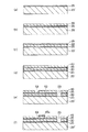
図6ないし図9は、インクジェット式記録ヘッドの製造方法を説明するための図(縦断面図)である。なお、以下の説明では、図6ないし図9中の上側を「上」、下側を「下」と言う。
本実施形態にかかるヘッド1の製造方法は、母材20’上に接合膜25を形成し、この接合膜25を介して母材20’と封止シート30とを接合する工程と、封止シート30上に接合膜35を形成し、この接合膜35を介して封止シート30と振動板40とを接合する工程と、接合膜25、封止シート30、接合膜35および振動板40の一部に貫通孔23を形成するとともに、振動板40の一部に凹部53を形成する工程と、振動板40上に接合膜45aを形成し、この接合膜45aを介して振動板40と圧電素子50とを接合する工程と、振動板40上に接合膜45bを形成し、この接合膜45bを介して振動板40とケースヘッド60とを接合する工程と、母材20’に対して加工を施し、基板20を形成する工程と、基板20の封止シート30と反対側の面上に接合膜15を形成し、この接合膜15を介して基板20とノズルプレート10とを接合する工程とを有する。
6 to 9 are views (longitudinal sectional views) for explaining a method of manufacturing the ink jet recording head. In the following description, the upper side in FIGS. 6 to 9 is referred to as “upper” and the lower side is referred to as “lower”.
The manufacturing method of the
以下、各工程について順次説明する。
[1]まず、基板20を作製するための母材として、母材20’を用意する。母材20’は、後述する工程において加工を施すことにより、基板20になり得るものである。
次に、図6(a)に示すように、母材20’上に、エネルギーを付与する前の状態の接合膜25を形成する。この接合膜25の形成方法は、後述する接合膜15の形成方法と同様である。
Hereinafter, each process will be described sequentially.
[1] First, a
Next, as shown in FIG. 6A, a
[2]次に、接合膜25に対してエネルギーを付与する。これにより、接合膜25に、封止シート30との接着性が発現する。なお、接合膜25に対するエネルギーの付与は、後述する接合膜15に対するエネルギーの付与方法と同様の方法で行うことができる。
[3]次に、封止シート30を用意する。そして、接着性が発現してなる接合膜25と封止シート30とが密着するように、母材20’と封止シート30とを貼り合わせる。これにより、図6(b)に示すように、母材20’と封止シート30とが、接合膜25を介して接合(接着)される。
[2] Next, energy is applied to the
[3] Next, the sealing
[4]次に、図6(c)に示すように、封止シート30上に、エネルギーを付与する前の状態の接合膜35を形成する。この接合膜35の形成方法は、後述する接合膜15の形成方法と同様である。
[5]次に、接合膜35に対してエネルギーを付与する。これにより、接合膜35に、振動板40との接着性が発現する。なお、接合膜35に対するエネルギーの付与は、後述する接合膜15に対するエネルギーの付与方法と同様の方法で行うことができる。
[4] Next, as shown in FIG. 6C, a
[5] Next, energy is applied to the
[6]次に、振動板40を用意する。そして、接着性が発現してなる接合膜35と振動板40とが密着するように、封止シート30を備えた母材20’と振動板40とを貼り合わせる。これにより、封止シート30と振動板40とが、接合膜35を介して接合(接着)される。その結果、図6(d)に示すように、母材20’、封止シート30および振動板40が接合される。
[6] Next, the
[7]次に、図6(e)に示すように、接合膜25、封止シート30、接合膜35および振動板40のうち、ヘッド1の吐出液供給室22に対応する位置に、貫通孔23を形成する。
また、振動板40のうち、圧電素子50が組み立てられる位置を取り囲む環状の領域に、凹部53を形成する。
貫通孔23および凹部53の形成は、ドライエッチング、リアクティブイオンエッチング、ビームエッチング、光アシストエッチング等の物理的エッチング法、ウエットエッチング等の化学的エッチング法等のうちの1種または2種以上を組み合わせて用いることができる。
[7] Next, as shown in FIG. 6 (e), the
Moreover, the recessed
The through-
[8]次に、図6(f)に示すように、振動板40上の圧電素子50が組み立てられる位置に、エネルギーを付与する前の状態の接合膜45aを形成する。この接合膜45aの形成方法は、後述する接合膜15の形成方法と同様である。
なお、振動板40上の一部の領域に部分的に接合膜45aを形成する場合、例えば、接合膜45aを形成すべき領域に対応する形状の窓部を有するマスクを介して、接合膜45aを成膜するようにすればよい。
[8] Next, as shown in FIG. 6F, a
When the
[9]次に、接合膜45aに対してエネルギーを付与する。これにより、接合膜45aに、圧電素子50との接着性が発現する。なお、接合膜45aに対するエネルギーの付与は、後述する接合膜15に対するエネルギーの付与方法と同様の方法で行うことができる。
[10]次に、圧電素子50を用意する。そして、接着性が発現してなる接合膜45aと圧電素子50とが密着するように、振動板40と圧電素子50とを貼り合わせる。これにより、振動板40と圧電素子50とが、接合膜45aを介して接合(接着)される。その結果、図7(g)に示すように、母材20’、封止シート30、振動板40および圧電素子50が接合される。
[9] Next, energy is applied to the
[10] Next, the
[11]次に、図7(h)に示すように、振動板40上のケースヘッド60が組み立てられる位置に、エネルギーを付与する前の状態の接合膜45bを形成する。この接合膜45bの形成方法は、後述する接合膜15の形成方法と同様である。
なお、振動板40上の一部の領域に部分的に接合膜45bを形成する場合、例えば、接合膜45bを形成すべき領域に対応する形状の窓部を有するマスクを介して、接合膜45bを成膜するようにすればよい。
[11] Next, as shown in FIG. 7H, a
When the
[12]次に、接合膜45bに対してエネルギーを付与する。これにより、接合膜45bに、ケースヘッド60との接着性が発現する。なお、接合膜45bに対するエネルギーの付与は、後述する接合膜15に対するエネルギーの付与方法と同様の方法で行うことができる。
[13]次に、ケースヘッド60を用意する。そして、接着性が発現してなる接合膜45bとケースヘッド60とが密着するように、振動板40とケースヘッド60とを貼り合わせる。これにより、振動板40とケースヘッド60とが、接合膜45bを介して接合(接着)される。その結果、図7(i)に示すように、母材20’、封止シート30、振動板40、圧電素子50およびケースヘッド60が接合される。
[12] Next, energy is applied to the
[13] Next, the
[14]次に、封止シート30、振動板40、圧電素子50およびケースヘッド60が接合された母材20’の上下を反転させる。そして、母材20’の封止シート30と反対側の面に対して加工を施し、各吐出液貯留室21および吐出液供給室22を形成する。これにより、母材20’から基板20を得る(図8(j)参照)。また、吐出液供給室22は、接合膜25、封止シート30、接合膜35および振動板40に形成された貫通孔23、および、ケースヘッド60に設けられた吐出液供給路61と連通し、リザーバ70が形成される。
[14] Next, the
母材20’の加工方法には、例えば、前述したような各種エッチング法を用いることができる。
なお、ここでは、封止シート30、振動板40、圧電素子50およびケースヘッド60が接合された母材20’に対して加工を施すことにより、各吐出液貯留室21および吐出液供給室22を形成する場合について説明したが、前記工程[1]の時点で、あらかじめ母材20’に各吐出液貯留室21および吐出液供給室22を設けておいてもよい。
As the processing method of the
Here, each of the discharge
[15]次に、基板20の封止シート30と反対側の面上に、ノズルプレート10を接合する。以下、基板20とノズルプレート10とを接合する方法について詳述する。
まず、封止シート30、振動板40、圧電素子50およびケースヘッド60が接合された基板20上に、プラズマ重合法により、エネルギーを付与する前の状態の接合膜15を形成する。プラズマ重合法は、例えば、強電界中に、原料ガスとキャリアガスとの混合ガスを供給することにより、原料ガス中の分子を重合させ、重合物を基板20上に堆積させ、膜を得る方法である。
[15] Next, the
First, the
以下、接合膜15をプラズマ重合法にて形成する方法について詳述するが、まず、接合膜15の形成方法を説明するのに先立って、基板20上にプラズマ重合法を行いて接合膜15を作製する際に用いるプラズマ重合装置について説明し、その後、接合膜15の形成方法について説明する。
図10は、本実施形態にかかるインクジェット式記録ヘッドが備える接合膜の作製に用いられるプラズマ重合装置を模式的に示す縦断面図である。なお、以下の説明では、図10中の上側を「上」、下側を「下」と言う。
Hereinafter, a method for forming the
FIG. 10 is a longitudinal sectional view schematically showing a plasma polymerization apparatus used for producing a bonding film included in the ink jet recording head according to the present embodiment. In the following description, the upper side in FIG. 10 is referred to as “upper” and the lower side is referred to as “lower”.
図10に示すプラズマ重合装置100は、チャンバー101と、基板20を支持する第1の電極130と、第2の電極140と、各電極130、140間に高周波電圧を印加する電源回路180と、チャンバー101内にガスを供給するガス供給部190と、チャンバー101内のガスを排気する排気ポンプ170とを備えている。これらの各部のうち、第1の電極130および第2の電極140がチャンバー101内に設けられている。以下、各部について詳細に説明する。
The
チャンバー101は、内部の気密を保持し得る容器であり、内部を減圧(真空)状態にして使用されるため、内部と外部との圧力差に耐え得る耐圧性能を有するものとされる。
図10に示すチャンバー101は、軸線が水平方向に沿って配置されたほぼ円筒形をなすチャンバー本体と、チャンバー本体の左側開口部を封止する円形の側壁と、右側開口部を封止する円形の側壁とで構成されている。
The
A
チャンバー101の上方には供給口103が、下方には排気口104が、それぞれ設けられている。そして、供給口103にはガス供給部190が接続され、排気口104には排気ポンプ170が接続されている。
なお、本実施形態では、チャンバー101は、導電性の高い金属材料で構成されており、接地線102を介して電気的に接地されている。
A
In this embodiment, the
第1の電極130は、板状をなしており、基板20を支持している。
この第1の電極130は、チャンバー101の側壁の内壁面に、鉛直方向に沿って設けられており、これにより、第1の電極130は、チャンバー101を介して電気的に接地されている。なお、第1の電極130は、図10に示すように、チャンバー本体と同心状に設けられている。
The
The
第1の電極130の基板20を支持する面には、静電チャック(吸着機構)139が設けられている。
この静電チャック139により、図10に示すように、基板20を鉛直方向に沿って支持することができる。また、基板20に多少の反りがあっても、静電チャック139に吸着させることにより、その反りを矯正した状態で基板20をプラズマ処理に供することができる。
An electrostatic chuck (suction mechanism) 139 is provided on the surface of the
The
第2の電極140は、基板20を介して、第1の電極130と対向して設けられている。なお、第2の電極140は、チャンバー101の側壁の内壁面から離間した(絶縁された)状態で設けられている。
この第2の電極140には、配線184を介して高周波電源182が接続されている。また、配線184の途中には、マッチングボックス(整合器)183が設けられている。これらの配線184、高周波電源182およびマッチングボックス183により、電源回路180が構成されている。
The
A high
このような電源回路180によれば、第1の電極130は接地されているので、第1の電極130と第2の電極140との間に高周波電圧が印加される。これにより、第1の電極130と第2の電極140との間隙には、高い周波数で向きが反転する電界が誘起される。
ガス供給部190は、チャンバー101内に所定のガスを供給するものである。
According to such a
The
図10に示すガス供給部190は、液状の膜材料(原料液)を貯留する貯液部191と、液状の膜材料を気化してガス状に変化させる気化装置192と、キャリアガスを貯留するガスボンベ193とを有している。また、これらの各部とチャンバー101の供給口103とが、それぞれ配管194で接続されており、ガス状の膜材料(原料ガス)とキャリアガスとの混合ガスを、供給口103からチャンバー101内に供給するように構成されている。
A
貯液部191に貯留される液状の膜材料は、プラズマ重合装置100により、重合して基板20の表面に重合膜を形成する原材料となるものである。
このような液状の膜材料は、気化装置192により気化され、ガス状の膜材料(原料ガス)となってチャンバー101内に供給される。なお、原料ガスについては、後に詳述する。
The liquid film material stored in the
Such a liquid film material is vaporized by the
ガスボンベ193に貯留されるキャリアガスは、電界の作用により放電し、およびこの放電を維持するために導入するガスである。このようなキャリアガスとしては、例えば、Arガス、Heガス等が挙げられる。
また、チャンバー101内の供給口103の近傍には、拡散板195が設けられている。
The carrier gas stored in the
A
拡散板195は、チャンバー101内に供給される混合ガスの拡散を促進する機能を有する。これにより、混合ガスは、チャンバー101内に、ほぼ均一の濃度で分散することができる。
排気ポンプ170は、チャンバー101内を排気するものであり、例えば、油回転ポンプ、ターボ分子ポンプ等で構成される。このようにチャンバー101内を排気して減圧することにより、ガスを容易にプラズマ化することができる。また、大気雰囲気との接触による基板20の汚染・酸化等を防止するとともに、プラズマ処理による反応生成物をチャンバー101内から効果的に除去することができる。
また、排気口104には、チャンバー101内の圧力を調整する圧力制御機構171が設けられている。これにより、チャンバー101内の圧力が、ガス供給部190の動作状況に応じて、適宜設定される。
The
The
The
次に、封止シート30、振動板40、圧電素子50およびケースヘッド60が接合された基板20上に、接合膜15を形成する方法について説明する。
[15−1]まず、ケースヘッド60が下側になるように、基板20をプラズマ重合装置100のチャンバー101内に収納して封止状態とした後、排気ポンプ170の作動により、チャンバー101内を減圧状態とする。
Next, a method for forming the
[15-1] First, the
次に、ガス供給部190を作動させ、チャンバー101内に原料ガスとキャリアガスの混合ガスを供給する。供給された混合ガスは、チャンバー101内に充填される。
ここで、混合ガス中における原料ガスの占める割合(混合比)は、原料ガスやキャリアガスの種類や目的とする成膜速度等によって若干異なるが、例えば、混合ガス中の原料ガスの割合を20〜70%程度に設定するのが好ましく、30〜60%程度に設定するのがより好ましい。これにより、重合膜の形成(成膜)の条件の最適化を図ることができる。
Next, the
Here, the ratio (mixing ratio) of the source gas in the mixed gas is slightly different depending on the type of the source gas and the carrier gas, the target film forming speed, and the like. For example, the ratio of the source gas in the mixed gas is 20 It is preferable to set to about -70%, and it is more preferable to set to about 30-60%. As a result, it is possible to optimize the conditions for formation (film formation) of the polymer film.
また、供給するガスの流量は、ガスの種類や目的とする成膜速度、膜厚等によって適宜決定され、特に限定されるものではないが、通常は、原料ガスおよびキャリアガスの流量を、それぞれ、1〜100ccm程度に設定するのが好ましく、10〜60ccm程度に設定するのがより好ましい。
次いで、電源回路180を作動させ、一対の電極130、140間に高周波電圧を印加する。これにより、一対の電極130、140間に存在するガスの分子が電離し、プラズマが発生する。このプラズマのエネルギーにより原料ガス中の分子が重合し、重合物が基板20上に付着・堆積する。これにより、図8(k)に示すように、基板20上にプラズマ重合膜で構成された接合膜15が形成される。
また、プラズマの作用により、基板20の表面が活性化・清浄化される。このため、原料ガスの重合物が基板20の表面に堆積し易くなり、接合膜15の安定した成膜が可能になる。このようにプラズマ重合法によれば、基板20の構成材料によらず、基板20と接合膜15との密着強度をより高めることができる。
Further, the flow rate of the gas to be supplied is appropriately determined depending on the type of gas, the target film formation rate, the film thickness, etc., and is not particularly limited, but usually the flow rates of the source gas and the carrier gas are respectively , Preferably about 1 to 100 ccm, more preferably about 10 to 60 ccm.
Next, the
Further, the surface of the
原料ガスとしては、例えば、メチルシロキサン、オクタメチルトリシロキサン、デカメチルテトラシロキサン、デカメチルシクロペンタシロキサン、オクタメチルシクロテトラシロキサン、メチルフェニルシロキサンのようなオルガノシロキサン等が挙げられる。
このような原料ガスを用いて得られるプラズマ重合膜、すなわち接合膜15は、これらの原料が重合してなるもの(重合物)、すなわちポリオルガノシロキサンで構成されることとなる。
Examples of the source gas include organosiloxanes such as methylsiloxane, octamethyltrisiloxane, decamethyltetrasiloxane, decamethylcyclopentasiloxane, octamethylcyclotetrasiloxane, and methylphenylsiloxane.
The plasma polymerized film obtained by using such a raw material gas, that is, the
プラズマ重合の際、一対の電極130、140間に印加する高周波の周波数は、特に限定されないが、1kHz〜100MHz程度であるのが好ましく、10〜60MHz程度であるのがより好ましい。
また、高周波の出力密度は、特に限定されないが、0.01〜100W/cm2程度であるのが好ましく、0.1〜50W/cm2程度であるのがより好ましく、1〜40W/cm2程度であるのがさらに好ましい。高周波の出力密度を前記範囲内とすることにより、高周波の出力密度が高過ぎて原料ガスに必要以上のプラズマエネルギーが付加されるのを防止しつつ、ランダムな原子構造を有するSi骨格301を確実に形成することができる。すなわち、高周波の出力密度が前記下限値を下回った場合、原料ガス中の分子に重合反応を生じさせることができず、接合膜15を形成することができないおそれがある。一方、高周波の出力密度が前記上限値を上回った場合、原料ガスが分解する等して、脱離基303となり得る構造がSi骨格301から分離してしまい、得られる接合膜15において脱離基303の含有率が著しく低くなったり、Si骨格301のランダム性が低下する(規則性が高くなる)おそれがある。
In the plasma polymerization, the frequency of the high frequency applied between the pair of
Further, the power density of the high frequency is not particularly limited, and is preferably about 0.01~100W / cm 2, more preferably about 0.1~50W / cm 2, 1~40W / cm 2 More preferably, it is about. By setting the high-frequency power density within the above range, the
また、成膜時のチャンバー101内の圧力は、133.3×10⁻⁵〜1333Pa(1×10⁻⁵〜10Torr)程度であるのが好ましく、133.3×10⁻⁴〜133.3Pa(1×10⁻⁴〜1Torr)程度であるのがより好ましい。
原料ガス流量は、0.5〜200sccm程度であるのが好ましく、1〜100sccm程度であるのがより好ましい。一方、キャリアガス流量は、5〜750sccm程度であるのが好ましく、10〜500sccm程度であるのがより好ましい。
Further, the pressure in the
The raw material gas flow rate is preferably about 0.5 to 200 sccm, and more preferably about 1 to 100 sccm. On the other hand, the carrier gas flow rate is preferably about 5 to 750 sccm, and more preferably about 10 to 500 sccm.
処理時間は、1〜10分程度であるのが好ましく、4〜7分程度であるのがより好ましい。なお、成膜される接合膜15の厚さは、主に、この処理時間に比例する。したがって、この処理時間を調整することのみで、接合膜15の厚さを容易に調整することができる。このため、従来は、接着剤を用いて基板とノズルプレートとを接着した場合、接着剤の厚さを厳密に制御することができなかったが、接合膜15によれば、接合膜15の厚さを厳密に制御することができるので、基板20とノズルプレート10との距離を厳密に制御することができる。
The treatment time is preferably about 1 to 10 minutes, more preferably about 4 to 7 minutes. Note that the thickness of the
また、基板20の温度は、25℃以上であるのが好ましく、25〜100℃程度であるのがより好ましい。
以上のようにして、接合膜15を得ることができる。
なお、基板20の上面のうち、ノズルプレート10を接合する領域のみに部分的に接合膜15を形成する場合、例えば、この領域に対応する形状の窓部を有するマスクを用い、このマスク上から接合膜15を成膜するようにすればよい。
Moreover, it is preferable that the temperature of the board |
The
In the case where the
[15−2]次に、基板20上に形成した接合膜15に対してエネルギーを付与する。
エネルギーが付与されると、接合膜15では、図4に示すように、脱離基303がSi骨格301から脱離する。そして、脱離基303が脱離した後には、図5に示すように、接合膜15の表面および内部に活性手304が生じる。これにより、接合膜15の表面に、ノズルプレート10との接着性が発現する。
[15-2] Next, energy is applied to the
When energy is applied, the leaving
ここで、接合膜15に付与するエネルギーは、いかなる方法で付与されてもよく、例えば、(I)接合膜15にエネルギー線を照射する方法、(II)接合膜15を加熱する方法、(III)接合膜15に圧縮力を付与する(物理的エネルギーを付与する)方法が代表的に挙げられ、この他、プラズマに曝す(プラズマエネルギーを付与する)方法、オゾンガスに曝す(化学的エネルギーを付与する)方法等が挙げられる。
このうち、接合膜15にエネルギーを付与する方法として、特に、上記(I)、(II)、(III)の各方法のうち、少なくとも1つの方法を用いるのが好ましい。これらの方法は、接合膜15に対して比較的簡単に効率よくエネルギーを付与することができるので、エネルギー付与方法として好適である。
Here, the energy applied to the
Among these, as a method for applying energy to the
以下、上記(I)、(II)、(III)の各方法について詳述する。
(I)接合膜15にエネルギー線を照射する場合、エネルギー線としては、例えば、紫外線、レーザー光のような光、X線、γ線、電子線、イオンビームのような粒子線等、またはこれらのエネルギー線を組み合わせたものが挙げられる。
これらのエネルギー線の中でも、特に、波長150〜300nm程度の紫外線を用いるのが好ましい(図8(L)参照)。かかる紫外線によれば、付与されるエネルギー量が最適化されるので、接合膜15中のSi骨格301が必要以上に破壊されるのを防止しつつ、Si骨格301と脱離基303との間の結合を選択的に切断することができる。これにより、接合膜15の特性(機械的特性、化学的特性等)が低下するのを防止しつつ、接合膜15に接着性を発現させることができる。
Hereinafter, the methods (I), (II), and (III) will be described in detail.
(I) In the case of irradiating the
Among these energy rays, it is particularly preferable to use ultraviolet rays having a wavelength of about 150 to 300 nm (see FIG. 8L). According to such ultraviolet rays, the amount of energy applied is optimized, so that the
また、紫外線によれば、広い範囲をムラなく短時間に処理することができるので、脱離基303の脱離を効率よく行わせることができる。さらに、紫外線には、例えば、UVランプ等の簡単な設備で発生させることができるという利点もある。
なお、紫外線の波長は、より好ましくは、160〜200nm程度とされる。
また、UVランプを用いる場合、その出力は、接合膜15の面積に応じて異なるが、1mW/cm2〜1W/cm2程度であるのが好ましく、5mW/cm2〜50mW/cm2程度であるのがより好ましい。なお、この場合、UVランプと接合膜15との離間距離は、3〜3000mm程度とするのが好ましく、10〜1000mm程度とするのがより好ましい。
In addition, since ultraviolet rays can be processed in a short time without unevenness, the leaving
The wavelength of ultraviolet light is more preferably about 160 to 200 nm.
In the case of using the UV lamp, the output may vary depending on the area of the
また、紫外線を照射する時間は、接合膜15の表面付近の脱離基303を脱離し得る程度の時間、すなわち、接合膜15の内部の脱離基303を多量に脱離させない程度の時間とするのが好ましい。具体的には、紫外線の光量、接合膜15の構成材料等に応じて若干異なるものの、0.5〜30分程度であるのが好ましく、1〜10分程度であるのがより好ましい。
Further, the time for irradiating the ultraviolet light is such a time that the leaving
また、紫外線は、時間的に連続して照射されてもよいが、間欠的(パルス状)に照射されてもよい。
一方、レーザー光としては、例えば、エキシマレーザー(フェムト秒レーザー)、Nd−YAGレーザー、Arレーザー、CO2レーザー、He−Neレーザー等が挙げられる。
Moreover, although an ultraviolet-ray may be irradiated continuously in time, you may irradiate intermittently (pulse form).
On the other hand, examples of the laser light include an excimer laser (femtosecond laser), an Nd-YAG laser, an Ar laser, a CO 2 laser, and a He—Ne laser.
また、接合膜15に対するエネルギー線の照射は、いかなる雰囲気中で行うようにしてもよく、具体的には、大気、酸素のような酸化性ガス雰囲気、水素のような還元性ガス雰囲気、窒素、アルゴンのような不活性ガス雰囲気、またはこれらの雰囲気を減圧した減圧(真空)雰囲気等が挙げられるが、特に大気雰囲気中で行うのが好ましい。これにより、雰囲気を制御することに手間やコストをかける必要がなくなり、エネルギー線の照射をより簡単に行うことができる。
The
このように、エネルギー線を照射する方法によれば、接合膜15に対して選択的にエネルギーを付与することが容易に行えるため、例えば、エネルギーの付与による基板20の変質・劣化を防止することができる。
また、エネルギー線を照射する方法によれば、付与するエネルギーの大きさを、精度よく簡単に調整することができる。このため、接合膜15から脱離する脱離基303の脱離量を調整することが可能となる。このように脱離基303の脱離量を調整することにより、接合膜15とノズルプレート10との間の接合強度を容易に制御することができる。
As described above, according to the method of irradiating the energy beam, it is possible to easily apply energy selectively to the
Moreover, according to the method of irradiating energy rays, the magnitude of energy to be applied can be easily adjusted with high accuracy. For this reason, it is possible to adjust the desorption amount of the leaving
すなわち、脱離基303の脱離量を多くすることにより、接合膜15の表面および内部に、より多くの活性手が生じるため、接合膜15に発現する接着性をより高めることができる。一方、脱離基303の脱離量を少なくすることにより、接合膜15の表面および内部に生じる活性手を少なくし、接合膜15に発現する接着性を抑えることができる。
なお、付与するエネルギーの大きさを調整するためには、例えば、エネルギー線の種類、エネルギー線の出力、エネルギー線の照射時間等の条件を調整すればよい。
さらに、エネルギー線を照射する方法によれば、短時間で大きなエネルギーを付与することができるので、エネルギーの付与をより効率よく行うことができる。
That is, by increasing the amount of elimination of the leaving
In addition, in order to adjust the magnitude | size of the energy to provide, what is necessary is just to adjust conditions, such as the kind of energy beam, the output of an energy beam, the irradiation time of an energy beam.
Furthermore, according to the method of irradiating energy rays, a large amount of energy can be applied in a short time, so that the energy can be applied more efficiently.
(II)接合膜15を加熱する場合(図示せず)、加熱温度を25〜100℃程度に設定するのが好ましく、50〜100℃程度に設定するのがより好ましい。かかる範囲の温度で加熱すれば、基板20等が熱によって変質・劣化するのを確実に防止しつつ、接合膜15を確実に活性化させることができる。
また、加熱時間は、接合膜15の分子結合を切断し得る程度の時間であればよく、具体的には、加熱温度が前記範囲内であれば、1〜30分程度であるのが好ましい。
(II) When the
The heating time may be a time that can break the molecular bond of the
また、接合膜15は、いかなる方法で加熱されてもよいが、例えば、ヒータを用いる方法、赤外線を照射する方法、火炎に接触させる方法等の各種加熱方法で加熱することができる。
なお、基板20とノズルプレート10の熱膨張率がほぼ等しい場合には、上記のような条件で接合膜15を加熱すればよいが、基板20とノズルプレート10の熱膨張率が互いに異なっている場合には、後に詳述するが、できるだけ低温下で接合を行うのが好ましい。接合を低温下で行うことにより、接合界面に発生する熱応力のさらなる低減を図ることができる。
The
When the thermal expansion coefficients of the
(III)本実施形態では、基板20とノズルプレート10とを貼り合わせる前に、接合膜15に対してエネルギーを付与する場合について説明しているが、かかるエネルギーの付与は、基板20とノズルプレート10とを重ね合わせた後に行われるようにしてもよい。すなわち、基板20上に接合膜15を形成した後、エネルギーを付与する前に、接合膜15とノズルプレート10とが密着するように、基板20とノズルプレート10とを重ね合わせて、仮接合体とする。そして、この仮接合体中の接合膜15に対してエネルギーを付与することにより、接合膜15に接着性が発現し、接合膜15を介して基板20とノズルプレート10とが接合(接着)される。
(III) In the present embodiment, the case where energy is applied to the
この場合、仮接合体中の接合膜15に対するエネルギーの付与は、前述した(I)、(II)の方法でもよいが、接合膜15に圧縮力を付与する方法を用いてもよい。
この場合、基板20とノズルプレート10とが互いに近づく方向に、0.2〜10MPa程度の圧力で圧縮するのが好ましく、1〜5MPa程度の圧力で圧縮するのがより好ましい。これにより、単に圧縮するのみで、接合膜15に対して適度なエネルギーを簡単に付与することができ、接合膜15に十分な接着性が発現する。なお、この圧力が前記上限値を上回っても構わないが、基板20とノズルプレート10の各構成材料によっては、基板20やノズルプレート10に損傷等が生じるおそれがある。
In this case, the application of energy to the
In this case, the
また、圧縮力を付与する時間は、特に限定されないが、10秒〜30分程度であるのが好ましい。なお、圧縮力を付与する時間は、圧縮力の大きさに応じて適宜変更すればよい。具体的には、圧縮力の大きさが大きいほど、圧縮力を付与する時間を短くすることができる。
なお、仮接合体の状態では、基板20とノズルプレート10との間が接合されていないので、これらの相対的な位置を容易に調整する(ずらす)ことができる。したがって、一旦、仮接合体を得た後、基板20とノズルプレート10との相対位置を微調整することにより、最終的に得られるヘッド1の組み立て精度(寸法精度)を確実に高めることができる。
The time for applying the compressive force is not particularly limited, but is preferably about 10 seconds to 30 minutes. In addition, what is necessary is just to change suitably the time which provides compression force according to the magnitude | size of compression force. Specifically, the time for applying the compressive force can be shortened as the compressive force increases.
In addition, in the state of a temporary joined body, since between the board |
以上のような(I)、(II)、(III)の各方法により、接合膜15にエネルギーを付与することができる。
なお、接合膜15の全面にエネルギーを付与するようにしてもよいが、一部の領域のみに付与するようにしてもよい。このようにすれば、接合膜15の接着性が発現する領域を制御することができ、この領域の面積・形状等を適宜調整することによって、接合界面に発生する応力の局所集中を緩和することができる。これにより、例えば、基板20とノズルプレート10の熱膨張率差が大きい場合でも、これらを確実に接合することができる。
Energy can be imparted to the
Note that energy may be applied to the entire surface of the
ここで、前述したように、エネルギーが付与される前の状態の接合膜15は、図4に示すように、Si骨格301と脱離基303とを有している。かかる接合膜15にエネルギーが付与されると、脱離基303(本実施形態では、メチル基)がSi骨格301から脱離する。これにより、図5に示すように、接合膜15の表面31に活性手304が生じ、活性化される。その結果、接合膜15の表面に接着性が発現する。
Here, as described above, the
ここで、接合膜15を「活性化させる」とは、接合膜15の表面31および内部の脱離基303が脱離して、Si骨格301において終端化されていない結合手(以下、「未結合手」または「ダングリングボンド」とも言う。)が生じた状態や、この未結合手が水酸基(OH基)によって終端化された状態、または、これらの状態が混在した状態のことを言う。
Here, “activating” the
したがって、活性手304とは、未結合手(ダングリングボンド)、または未結合手が水酸基によって終端化されたもののことを言う。このような活性手304によれば、ノズルプレート10に対して、特に強固な接合が可能となる。
なお、後者の状態(未結合手が水酸基によって終端化された状態)は、例えば、接合膜15に対して大気雰囲気中でエネルギー線を照射することにより、大気中の水分が未結合手を終端化することによって、容易に生成することができる。
Therefore, the
The latter state (state in which dangling bonds are terminated by a hydroxyl group) is obtained by, for example, irradiating the
[15−3]次に、ノズルプレート10を用意する。そして、図9(m)に示すように、接着性が発現してなる接合膜15とノズルプレート10とが密着するように、基板20とノズルプレート10とを貼り合わせる。これにより、図9(n)に示すように、基板20とノズルプレート10とが、接合膜15を介して接合(接着)される。
ここで、上記のようにして接合される基板20とノズルプレート10の各熱膨張率は、ほぼ等しいのが好ましい。基板20とノズルプレート10の熱膨張率がほぼ等しければ、これらを貼り合せた際に、その接合界面に熱膨張に伴う応力が発生し難くなる。その結果、最終的に得られるヘッド1において、剥離等の不具合が発生するのを確実に防止することができる。
[15-3] Next, the
Here, it is preferable that the thermal expansion coefficients of the
また、基板20とノズルプレート10の各熱膨張率が互いに異なる場合でも、基板20とノズルプレート10とを貼り合わせる際の条件を以下のように最適化することにより、基板20とノズルプレート10とを高い寸法精度で強固に接合することができる。
すなわち、基板20とノズルプレート10の熱膨張率が互いに異なっている場合には、できるだけ低温下で接合を行うのが好ましい。接合を低温下で行うことにより、接合界面に発生する熱応力のさらなる低減を図ることができる。
Even when the thermal expansion coefficients of the
That is, when the thermal expansion coefficients of the
具体的には、基板20とノズルプレート10との熱膨張率差にもよるが、基板20とノズルプレート10の温度が25〜50℃程度である状態下で、基板20とノズルプレート10とを貼り合わせるのが好ましく、25〜40℃程度である状態下で貼り合わせるのがより好ましい。このような温度範囲であれば、基板20とノズルプレート10の熱膨張率差がある程度大きくても、接合界面に発生する熱応力を十分に低減することができる。その結果、ヘッド1における反りや剥離等の発生を確実に防止することができる。
Specifically, depending on the difference in thermal expansion coefficient between the
また、この場合、基板20とノズルプレート10との間の熱膨張係数の差が、5×10⁻⁵/K以上あるような場合には、上記のようにして、できるだけ低温下で接合を行うことが特に推奨される。なお、接合膜15を用いることにより、上述したような低温下でも、基板20とノズルプレート10とを強固に接合することができる。
In this case, when the difference in thermal expansion coefficient between the
また、基板20とノズルプレート10は、互いに剛性が異なっているのが好ましい。これにより、基板20とノズルプレート10とをより強固に接合することができる。
なお、基板20の接合膜15を成膜する領域には、あらかじめ、接合膜15との密着性を高める表面処理を施すのが好ましい。これにより、基板20と接合膜15との間の接合強度をより高めることができ、最終的には、基板20とノズルプレート10との接合強度を高めることができる。
The
In addition, it is preferable to perform a surface treatment for improving adhesion to the
かかる表面処理としては、例えば、スパッタリング処理、ブラスト処理のような物理的表面処理、酸素プラズマ、窒素プラズマ等を用いたプラズマ処理、コロナ放電処理、エッチング処理、電子線照射処理、紫外線照射処理、オゾン暴露処理のような化学的表面処理、または、これらを組み合わせた処理等が挙げられる。このような処理を施すことにより、基板20の接合膜15を成膜する領域を清浄化するとともに、該領域を活性化させることができる。
Examples of the surface treatment include physical surface treatment such as sputtering treatment and blast treatment, plasma treatment using oxygen plasma, nitrogen plasma, etc., corona discharge treatment, etching treatment, electron beam irradiation treatment, ultraviolet irradiation treatment, ozone Examples include chemical surface treatment such as exposure treatment, or a combination of these. By performing such treatment, the region of the
また、これらの各表面処理の中でもプラズマ処理を用いることにより、接合膜15を形成するために、基板20の表面を特に最適化することができる。
なお、表面処理を施す基板20が、樹脂材料(高分子材料)で構成されている場合には、特に、コロナ放電処理、窒素プラズマ処理等が好適に用いられる。
また、基板20の構成材料によっては、上記のような表面処理を施さなくても、接合膜15の接合強度が十分に高くなるものがある。このような効果が得られる基板20の構成材料としては、例えば、前述したような各種金属系材料、各種シリコン系材料、各種ガラス系材料等を主材料とするものが挙げられる。
Further, by using plasma treatment among these surface treatments, the surface of the
When the
Further, depending on the constituent material of the
このような材料で構成された基板20は、その表面が酸化膜で覆われており、この酸化膜の表面には、比較的活性の高い水酸基が結合している。したがって、このような材料で構成された基板20を用いると、上記のような表面処理を施さなくても、基板20と接合膜15とを強固に密着させることができる。
なお、この場合、基板20の全体が上記のような材料で構成されていなくてもよく、少なくとも接合膜15を成膜する領域の表面付近が上記のような材料で構成されていればよい。
The surface of the
In this case, the
さらに、基板20の接合膜15を成膜する領域に、以下の基や物質を有する場合には、上記のような表面処理を施さなくても、基板20と接合膜15との接合強度を十分に高くすることができる。
このような基や物質としては、例えば、水酸基、チオール基、カルボキシル基、アミノ基、ニトロ基、イミダゾール基のような官能基、ラジカル、開環分子、2重結合、3重結合のような不飽和結合、F、Cl、Br、Iのようなハロゲン、過酸化物からなる群から選択される少なくとも1つの基または物質が挙げられる。
Further, when the region where the
Examples of such groups and substances include functional groups such as hydroxyl groups, thiol groups, carboxyl groups, amino groups, nitro groups, and imidazole groups, radicals, ring-opened molecules, double bonds, and triple bonds. And at least one group or substance selected from the group consisting of a saturated bond, a halogen such as F, Cl, Br, and I, and a peroxide.
また、このようなものを有する表面が得られるように、上述したような各種表面処理を適宜選択して行うのが好ましい。
また、表面処理に代えて、基板20の少なくとも接合膜15を成膜する領域には、あらかじめ、中間層を形成しておくのが好ましい。
この中間層は、いかなる機能を有するものであってもよく、例えば、接合膜15との密着性を高める機能、クッション性(緩衝機能)、応力集中を緩和する機能等を有するものが好ましい。このような中間層を介して基板20上に接合膜15を成膜することにより、基板20と接合膜15との接合強度を高め、信頼性の高い接合体、すなわちヘッド1を得ることができる。
Further, it is preferable to appropriately select and perform various surface treatments as described above so that a surface having such a material can be obtained.
In place of the surface treatment, it is preferable to form an intermediate layer in advance in at least the region of the
The intermediate layer may have any function. For example, a layer having a function of improving adhesion to the
かかる中間層の構成材料としては、例えば、アルミニウム、チタンのような金属系材料、金属酸化物、シリコン酸化物のような酸化物系材料、金属窒化物、シリコン窒化物のような窒化物系材料、グラファイト、ダイヤモンドライクカーボンのような炭素系材料、シランカップリング剤、チオール系化合物、金属アルコキシド、金属−ハロゲン化合物のような自己組織化膜材料等が挙げられ、これらのうちの1種または2種以上を組み合わせて用いることができる。
また、これらの各材料で構成された中間層の中でも、酸化物系材料で構成された中間層によれば、基板20と接合膜15との間の接合強度を特に高めることができる。
Examples of the constituent material of the intermediate layer include metal materials such as aluminum and titanium, metal oxides, oxide materials such as silicon oxide, metal nitrides, and nitride materials such as silicon nitride. , Carbon-based materials such as graphite and diamond-like carbon, silane coupling agents, thiol-based compounds, metal alkoxides, and self-assembled film materials such as metal-halogen compounds. A combination of more than one species can be used.
Further, among the intermediate layers formed of these materials, the intermediate layer formed of the oxide-based material can particularly increase the bonding strength between the
一方、ノズルプレート10の接合膜15と接触する領域にも、あらかじめ、接合膜15との密着性を高める表面処理を施すのが好ましい。これにより、ノズルプレート10と接合膜15との間の接合強度をより高めることができる。
なお、この表面処理には、基板20に対して施す前述したような表面処理と同様の処理を適用することができる。
On the other hand, it is preferable to perform a surface treatment for improving the adhesion with the
For this surface treatment, the same treatment as the above-described surface treatment performed on the
また、表面処理に代えて、ノズルプレート10の接合膜15と接触する領域に、あらかじめ、接合膜15との密着性を高める機能を有する中間層を形成しておくのが好ましい。これにより、ノズルプレート10と接合膜15との間の接合強度をより高めることができる。
かかる中間層の構成材料には、前述の基板20に形成する中間層の構成材料と同様のものを用いることができる。
Moreover, it is preferable to form an intermediate layer having a function of improving the adhesion with the
As the constituent material of the intermediate layer, the same constituent material as that of the intermediate layer formed on the
なお、基板20やノズルプレート10に対する前述の表面処理および中間層の形成は、言うまでもなく、封止シート30、振動板40、圧電素子50およびケースヘッド60に対して行うようにしてもよい。これにより、各部の接合強度をより高めることができる。
ここで、本工程において、接合膜15を備える基板20とノズルプレート10とが接合されるメカニズムについて説明する。
Needless to say, the surface treatment and the formation of the intermediate layer on the
Here, a mechanism in which the
例えば、ノズルプレート10の基板20との接合に供される領域に、水酸基が露出している場合を例に説明すると、本工程において、接合膜15とノズルプレート10とが接触するように、基板20とノズルプレート10とを貼り合わせたとき、接合膜15の表面31に存在する水酸基と、ノズルプレート10の前記領域に存在する水酸基とが、水素結合によって互いに引き合い、水酸基同士の間に引力が発生する。この引力によって、接合膜15を備える基板20とノズルプレート10とが接合されると推察される。
For example, the case where a hydroxyl group is exposed in the region of the
また、この水素結合によって互いに引き合う水酸基同士は、温度条件等によって、脱水縮合する。その結果、接合膜15とノズルプレート10との接触界面では、水酸基が結合していた結合手同士が酸素原子を介して結合する。これにより、接合膜15を介して基板20とノズルプレート10とがより強固に接合されると推察される。
なお、前記工程[15−2]で活性化された接合膜15の表面は、その活性状態が経時的に緩和してしまう。このため、前記工程[15−2]の終了後、できるだけ早く本工程[15−3]を行うようにするのが好ましい。具体的には、前記工程[15−2]の終了後、60分以内に本工程[15−3]を行うようにするのが好ましく、5分以内に行うのがより好ましい。かかる時間内であれば、接合膜15の表面が十分な活性状態を維持しているので、本工程で接合膜15を備える基板20とノズルプレート10とを貼り合わせたとき、これらの間に十分な接合強度を得ることができる。
Further, the hydroxyl groups attracting each other by this hydrogen bond are dehydrated and condensed depending on the temperature condition or the like. As a result, at the contact interface between the
Note that the active state of the surface of the
このようにして接合された基板20とノズルプレート10との間は、その接合強度が5MPa(50kgf/cm2)以上であるのが好ましく、10MPa(100kgf/cm2)以上であるのがより好ましい。このような接合強度であれば、接合界面の剥離を十分に防止し得るものとなる。そして、信頼性の高いヘッド1が得られる。
以上のような工程を経て、ヘッド1が製造される。
The bonding strength between the
The
なお、上記では、基板20上に成膜された接合膜15とノズルプレート10とが密着するように、基板20とノズルプレート10とを貼り合わせる場合について説明しているが、ノズルプレート10の下面に成膜された接合膜15と基板20とが密着するように、基板20とノズルプレート10とを貼り合わせるようにしてもよい。
また、接合膜15は、基板20とノズルプレート10の双方に成膜されていてもよい。
In the above description, the case where the
Further, the
図11は、本実施形態にかかるヘッドの他の構成例を示す図である。なお、以下の説明では、図11中の上側を「上」、下側を「下」と言う。
図11に示すヘッド1では、基板20の下面に成膜された接合膜15と、ノズルプレート10の上面に成膜された接合膜15とが密着するように、基板20とノズルプレート10とを貼り合わせることにより、これらが接合(接着)されている。
FIG. 11 is a diagram illustrating another configuration example of the head according to the present embodiment. In the following description, the upper side in FIG. 11 is referred to as “upper” and the lower side is referred to as “lower”.
In the
また、これと同様に、図11に示すヘッド1では、基板20の上面に成膜された接合膜25と、封止シート30の下面に成膜された接合膜25とが密着するように、基板20と封止シート30とを貼り合わせることにより、これらが接合(接着)されている。
さらに、封止シート30の上面に成膜された接合膜35と、振動板40の下面に成膜された接合膜35とが密着するように、封止シート30と振動板40とを貼り合わせることにより、これらが接合(接着)されている。
Similarly, in the
Further, the sealing
また、振動板40の上面に成膜された接合膜45aと、圧電素子50の下面に成膜された接合膜45aとが密着するように、振動板40と圧電素子50とを貼り合わせることにより、これらが接合(接着)されている。
さらに、振動板40の上面に成膜された接合膜45bと、ケースヘッド60の下面に成膜された接合膜45bとが密着するように、振動板40とケースヘッド60とを貼り合わせることにより、これらが接合(接着)されている。
Further, the
Further, the
このような構成のヘッド1によれば、各部の界面をさらに強固に接合することができる。また、このようなヘッド1では、被着体(例えば、基板、ノズルプレート、封止シート、振動板、圧電素子,ケースヘッド等)の材質が接合強度に影響を及ぼし難いため、被着体の材質によらず、各部が強固に接合された信頼性の高いヘッド1が得られる。
なお、この場合、例えば、接合膜15に対するエネルギーの付与は、基板20の下面に成膜された接合膜15と、ノズルプレート10の上面に成膜された接合膜15のそれぞれに対して行うようにすればよい。
また、ヘッド1を得た後、このヘッド1に対して、必要に応じ、以下の2つの工程([16A]および[16B])のうちの少なくとも1つの工程(ヘッド1の接合強度を高める工程)を行うようにしてもよい。これにより、ヘッド1の各部の接合強度のさらなる向上を図ることができる。
According to the
In this case, for example, application of energy to the
In addition, after obtaining the
[16A]得られたヘッド1を圧縮するように、すなわちノズルプレート10、基板20、封止シート30、振動板40およびケースヘッド60が互いに近づく方向に加圧する。
これにより、上記各部の表面と隣接する接合膜の表面とがより近接し、ヘッド1における接合強度をより高めることができる。
[16A] The obtained
Thereby, the surface of each said part and the surface of the adjacent joining film | membrane come closer, and the joint strength in the
また、ヘッド1を加圧することにより、ヘッド1中の接合界面に残存していた隙間を押し潰して、接合面積をさらに広げることができる。これにより、ヘッド1における接合強度をさらに高めることができる。
このとき、ヘッド1を加圧する際の圧力は、ヘッド1が損傷を受けない程度の圧力で、できるだけ高い方が好ましい。これにより、この圧力に比例してヘッド1における接合強度を高めることができる。
Further, by pressurizing the
At this time, the pressure when pressurizing the
なお、この圧力は、ヘッド1の各部の構成材料や形状、接合装置等の条件に応じて、適宜調整すればよい。具体的には、上記条件に応じて若干異なるものの、0.2〜10MPa程度であるのが好ましく、1〜5MPa程度であるのがより好ましい。これにより、ヘッド1の接合強度を確実に高めることができる。なお、この圧力が前記上限値を上回っても構わないが、ヘッド1の各部の構成材料によっては、ヘッド1に損傷等が生じるおそれがある。
また、加圧する時間は、特に限定されないが、10秒〜30分程度であるのが好ましい。なお、加圧する時間は、加圧する際の圧力に応じて適宜変更すればよい。具体的には、ヘッド1を加圧する際の圧力が高いほど、加圧する時間を短くしても、接合強度の向上を図ることができる。
In addition, what is necessary is just to adjust this pressure suitably according to conditions, such as a constituent material and shape of each part of the
The time for pressurization is not particularly limited, but is preferably about 10 seconds to 30 minutes. In addition, what is necessary is just to change suitably the time to pressurize according to the pressure at the time of pressurizing. Specifically, the higher the pressure at which the
[16B]得られたヘッド1を加熱する。
これにより、ヘッド1における接合強度をより高めることができる。
このとき、ヘッド1を加熱する際の温度は、室温より高く、ヘッド1の耐熱温度未満であれば、特に限定されないが、好ましくは25〜100℃程度とされ、より好ましくは50〜100℃程度とされる。かかる範囲の温度で加熱すれば、ヘッド1が熱によって変質・劣化するのを確実に防止しつつ、接合強度を確実に高めることができる。
[16B] The obtained
Thereby, the joint strength in the
At this time, the temperature at which the
また、加熱時間は、特に限定されないが、1〜30分程度であるのが好ましい。
なお、前記工程[16A]、[16B]の双方を行う場合、これらを同時に行うのが好ましい。すなわち、ヘッド1を加圧しつつ、加熱するのが好ましい。これにより、加圧による効果と、加熱による効果とが相乗的に発揮され、ヘッド1の接合強度を特に高めることができる。
以上のような工程を行うことにより、ヘッド1における接合強度のさらなる向上を容易に図ることができる。
The heating time is not particularly limited, but is preferably about 1 to 30 minutes.
In addition, when performing both said process [16A] and [16B], it is preferable to perform these simultaneously. That is, it is preferable to heat the
By performing the steps as described above, it is possible to easily further improve the bonding strength in the
≪第2実施形態≫
次に、本発明の液滴吐出ヘッドをインクジェット式記録ヘッドに適用した場合の第2実施形態について説明する。
図12は、本発明の液滴吐出ヘッドをインクジェット式記録ヘッドに適用した場合の第2実施形態が備える接合膜のエネルギー付与前の状態を示す部分拡大図、図13は、本発明の液滴吐出ヘッドをインクジェット式記録ヘッドに適用した場合の第2実施形態が備える接合膜のエネルギー付与後の状態を示す部分拡大図である。なお、以下の説明では、図12および図13中の上側を「上」、下側を「下」と言う。
<< Second Embodiment >>
Next, a second embodiment in which the droplet discharge head of the present invention is applied to an ink jet recording head will be described.
FIG. 12 is a partially enlarged view showing a state before energy application of the bonding film included in the second embodiment when the droplet discharge head of the present invention is applied to an ink jet recording head, and FIG. 13 is a droplet of the present invention. It is the elements on larger scale which show the state after the energy provision of the joining film with which 2nd Embodiment with which an ejection head is applied to an inkjet recording head is provided. In the following description, the upper side in FIGS. 12 and 13 is referred to as “upper” and the lower side is referred to as “lower”.
以下、インクジェット式記録ヘッドの第2実施形態について説明するが、前記第1実施形態にかかるインクジェット式記録ヘッドとの相違点を中心に説明し、同様の事項については、その説明を省略する。
本実施形態にかかるインクジェット式記録ヘッドは、各接合膜の構成が異なること以外は、前記第1実施形態と同様である。
すなわち、本実施形態にかかるインクジェット式記録ヘッドは、各接合膜15、25、35、45a、45bがそれぞれエネルギー付与前の状態で、金属原子と、この金属原子に結合する酸素原子と、これら金属原子および酸素原子の少なくとも一方に結合する脱離基303とを含むものである。換言すれば、エネルギー付与前の各接合膜15、25、35、45a、45bは、それぞれ、金属酸化物で構成される金属酸化物膜に脱離基303を導入した膜であると言うことができる。
Hereinafter, the second embodiment of the ink jet recording head will be described, but the description will focus on differences from the ink jet recording head according to the first embodiment, and the description of the same matters will be omitted.
The ink jet recording head according to this embodiment is the same as that of the first embodiment except that the configuration of each bonding film is different.
In other words, the ink jet recording head according to the present embodiment includes the metal atoms, the oxygen atoms bonded to the metal atoms, and the metal atoms in the state where each of the
このような各接合膜15、25、35、45a、45bは、エネルギーが付与されると、脱離基303が金属原子および酸素原子の少なくとも一方から脱離し、各接合膜15、25、35、45a、45bの少なくとも表面付近に、活性手304が生じるものである。そして、これにより、各接合膜15、25、35、45a、45bの表面に、前記第1実施形態と同様の接着性が発現する。
In each of the
以下、本実施形態にかかる各接合膜15、25、35、45a、45bについて説明するが、これらの構成は共通であるため、接合膜15を代表に説明する。
接合膜15は、金属原子と、この金属原子と結合する酸素原子とで構成されるもの、すなわち金属酸化物に脱離基303が結合したものであることから、変形し難い強固な膜となる。このため、接合膜15自体が寸法精度の高いものとなり、最終的に得られるヘッド1においても、寸法精度が高いものが得られる。
Hereinafter, the
The
さらに、接合膜15は、流動性を有さない固体状をなすものである。このため、従来から用いられている、流動性を有する液状または粘液状(半固形状)の接着剤に比べて、接着層(接合膜15)の厚さや形状がほとんど変化しない。したがって、接合膜15を用いて得られたヘッド1の寸法精度は、従来に比べて格段に高いものとなる。さらに、接着剤の硬化に要する時間が不要になるため、短時間で強固な接合が可能となる。
Further, the
また、本発明では、接合膜15は、導電性を有するものであるのが好ましい。これにより、後述するヘッド1において、意図しない帯電を抑制または防止することができる。その結果、インクの吐出方向を確実に制御することができる。
また、接合膜15が導電性を有する場合、接合膜15の抵抗率は、構成材料の組成に応じて若干異なるものの、1×10⁻³Ω・cm以下であるのが好ましく、1×10⁻⁴Ω・cm以下であるのがより好ましい。
In the present invention, it is preferable that the
Also, if the
なお、脱離基303は、少なくとも接合膜15の表面31付近に存在していればよく、接合膜15のほぼ全体に存在していてもよいし、接合膜15の表面31付近に偏在していてもよい。なお、脱離基303が表面31付近に偏在する構成とすることにより、接合膜15に金属酸化物膜としての機能を好適に発揮させることができる。すなわち、接合膜15に、接合を担う機能の他に、導電性や透光性等の特性に優れた金属酸化物膜としての機能を好適に付与することができるという利点も得られる。換言すれば、脱離基303が、接合膜15の導電性や透光性等の特性を阻害してしまうのを確実に防止することができる。
The leaving
以上のような接合膜15としての機能が好適に発揮されるように、金属原子が選択される。
具体的には、金属原子としては、特に限定されないが、例えば、Li、Be、B、Na、Mg、Al、K、Ca、Sc、V、Cr、Mn、Fe、Co、Ni、Cu、Zn、Ga、Rb、Sr、Y、Zr、Nb、Mo、Cd、In、Sn、Sb、Cs、Ba、La、Hf、Ta、W、TiおよびPb等が挙げられる。中でも、In(インジウム)、Sn(スズ)、Zn(亜鉛)、Ti(チタン)およびSb(アンチモン)のうちの1種または2種以上を組み合わせて用いるのが好ましい。接合膜15を、これらの金属原子を含むもの、すなわちこれらの金属原子を含む金属酸化物に脱離基303を導入したものとすることにより、接合膜15は、優れた導電性と透明性とを発揮するものとなる。
The metal atoms are selected so that the function as the
Specifically, the metal atom is not particularly limited. For example, Li, Be, B, Na, Mg, Al, K, Ca, Sc, V, Cr, Mn, Fe, Co, Ni, Cu, Zn Ga, Rb, Sr, Y, Zr, Nb, Mo, Cd, In, Sn, Sb, Cs, Ba, La, Hf, Ta, W, Ti, Pb, and the like. Among these, it is preferable to use one or more of In (indium), Sn (tin), Zn (zinc), Ti (titanium), and Sb (antimony) in combination. By using the
より具体的には、金属酸化物としては、例えば、インジウム錫酸化物(ITO)、インジウム亜鉛酸化物(IZO)、アンチモン錫酸化物(ATO)、フッ素含有インジウム錫酸化物(FTO)、酸化亜鉛(ZnO)および二酸化チタン(TiO2)等が挙げられる。
なお、金属酸化物としてインジウム錫酸化物(ITO)を用いる場合には、インジウムとスズとの原子比(インジウム/スズ比)は、99/1〜80/20であるのが好ましく、97/3〜85/15であるのがより好ましい。これにより、前述したような効果をより顕著に発揮させることができる。
More specifically, examples of the metal oxide include indium tin oxide (ITO), indium zinc oxide (IZO), antimony tin oxide (ATO), fluorine-containing indium tin oxide (FTO), and zinc oxide. (ZnO) and titanium dioxide (TiO 2), and the like.
When indium tin oxide (ITO) is used as the metal oxide, the atomic ratio of indium to tin (indium / tin ratio) is preferably 99/1 to 80/20, and 97/3 More preferably, it is -85/15. Thereby, the effects as described above can be more remarkably exhibited.
また、接合膜15中の金属原子と酸素原子の存在比は、3:7〜7:3程度であるのが好ましく、4:6〜6:4程度であるのがより好ましい。金属原子と酸素原子の存在比を前記範囲内になるよう設定することにより、接合膜15の安定性が高くなり、基板20とノズルプレート10とをより強固に接合することができるようになる。
また、脱離基303は、前述したように、金属原子および酸素原子の少なくとも一方から脱離することにより、接合膜15に活性手を生じさせるよう振る舞うものである。したがって、脱離基303には、エネルギーを付与されることによって、比較的簡単に、かつ均一に脱離するものの、エネルギーが付与されないときには、脱離しないよう接合膜15に確実に結合しているものが好適に選択される。
The abundance ratio of metal atoms and oxygen atoms in the
Further, as described above, the leaving
かかる観点から、脱離基303には、水素原子、炭素原子、窒素原子、リン原子、硫黄原子およびハロゲン原子、またはこれらの各原子で構成される原子団のうちの少なくとも1種が好適に用いられる。かかる脱離基303は、エネルギーの付与による結合/脱離の選択性に比較的優れている。このため、このような脱離基303は、上記のような必要性を十分に満足し得るものとなり、基板20とノズルプレート10との接着性をより高度なものとすることができる。
From this viewpoint, the leaving
なお、上記の各原子で構成される原子団(基)としては、例えば、メチル基、エチル基のようなアルキル基、メトキシ基、エトキシ基のようなアルコキシ基、カルボキシル基、アミノ基およびスルホン酸基等が挙げられる。
以上のような各原子および原子団の中でも、脱離基303は、特に、水素原子であるのが好ましい。水素原子で構成される脱離基303は、化学的な安定性が高いため、脱離基303として水素原子を備える接合膜15は、耐候性および耐薬品性に優れたものとなる。
Examples of the atomic group (group) composed of the above atoms include, for example, an alkyl group such as a methyl group and an ethyl group, an alkoxy group such as a methoxy group and an ethoxy group, a carboxyl group, an amino group, and a sulfonic acid. Groups and the like.
Among the atoms and atomic groups as described above, the leaving
以上のことを考慮すると、接合膜15としては、インジウム錫酸化物(ITO)、インジウム亜鉛酸化物(IZO)、アンチモン錫酸化物(ATO)、フッ素含有インジウム錫酸化物(FTO)、酸化亜鉛(ZnO)または二酸化チタン(TiO2)の金属酸化物に、脱離基303として水素原子が導入されたものが好適に選択される。
かかる構成の接合膜15は、それ自体が優れた機械的特性を有している。また、多くの材料に対して特に優れた接着性を示すものである。したがって、このような接合膜15は、基板20に対して特に強固に接着するとともに、ノズルプレート10に対しても特に強い被着力を示し、その結果として、基板20とノズルプレート10とを強固に接合することができる。
Considering the above, the
The
また、接合膜15の平均厚さは、1〜1000nm程度であるのが好ましく、2〜800nm程度であるのがより好ましい。接合膜15の平均厚さを前記範囲内とすることにより、ヘッド1の寸法精度が著しく低下するのを防止しつつ、基板20とノズルプレート10とをより強固に接合することができる。
すなわち、接合膜15の平均厚さが前記下限値を下回った場合は、十分な接合強度が得られないおそれがある。一方、接合膜15の平均厚さが前記上限値を上回った場合は、ヘッド1の寸法精度が著しく低下するおそれがある。
The average thickness of the
That is, when the average thickness of the
さらに、接合膜15の平均厚さが前記範囲内であれば、接合膜15にある程度の形状追従性が確保される。このため、例えば、基板20の接合面(接合膜15を成膜する面)に凹凸が存在している場合でも、その凹凸の高さにもよるが、凹凸の形状に追従するように接合膜15を被着させることができる。その結果、接合膜15は、凹凸を吸収して、その表面に生じる凹凸の高さを緩和することができる。そして、基板20とノズルプレート10とを貼り合わせた際に、接合膜15のノズルプレート10に対する密着性を高めることができる。
Furthermore, if the average thickness of the
なお、上記のような形状追従性の程度は、接合膜15の厚さが厚いほど顕著になる。したがって、形状追従性を十分に確保するためには、接合膜15の厚さをできるだけ厚くすればよい。
以上説明したような接合膜15は、接合膜15のほぼ全体に脱離基303を存在させる場合には、例えば、A:脱離基303を構成する原子成分を含む雰囲気下で、物理的気相成膜法により、金属原子と酸素原子とを含む金属酸化物材料を成膜することにより形成することができる。また、脱離基303を接合膜15の表面31付近に偏在させる場合には、例えば、B:金属原子と前記酸素原子とを含む金属酸化物膜を成膜した後、この金属酸化物膜の表面付近に含まれる金属原子および酸素原子の少なくとも一方に脱離基303を導入することにより形成することができる。
In addition, the degree of the shape followability as described above becomes more prominent as the
In the
以下、AおよびBの方法を用いて、基板20上に接合膜15を成膜する場合について、詳述する。
<A> Aの方法では、接合膜15は、上記のように、脱離基303を構成する原子成分を含む雰囲気下で、物理的気相成膜法(PVD法)により、金属原子と酸素原子とを含む金属酸化物材料を成膜することにより形成される。このようにPVD法を用いる構成とすれば、金属酸化物材料を基板20に向かって飛来させる際に、比較的容易に金属原子および酸素原子の少なくとも一方に脱離基303を導入することができる。このため、接合膜15のほぼ全体にわたって脱離基303を導入することができる。
Hereinafter, the case where the
<A> In the method A, as described above, the
さらに、PVD法によれば、緻密で均質な接合膜15を効率よく成膜することができる。これにより、PVD法で成膜された接合膜15は、ノズルプレート10に対して特に強固に接合し得るものとなる。さらに、PVD法で成膜された接合膜15は、エネルギーが付与されて活性化された状態が比較的長時間にわたって維持される。このため、ヘッド1の製造過程の簡素化、効率化を図ることができる。
Furthermore, according to the PVD method, a dense and
また、PVD法としては、真空蒸着法、スパッタリング法、イオンプレーティング法、レーザーアブレーション法等が挙げられるが、中でも、スパッタリング法を用いるのが好ましい。スパッタリング法によれば、金属原子と酸素原子との結合が切断することなく、脱離基303を構成する原子成分を含む雰囲気中に、金属酸化物の粒子を叩き出すことができる。そして、金属酸化物の粒子が叩き出された状態で、脱離基303を構成する原子成分を含むガスと接触させることができるため、金属酸化物(金属原子または酸素原子)への脱離基303の導入をより円滑に行うことができる。
Further, examples of the PVD method include a vacuum deposition method, a sputtering method, an ion plating method, a laser ablation method, and the like. Among these, the sputtering method is preferably used. According to the sputtering method, metal oxide particles can be knocked out into an atmosphere containing an atomic component constituting the leaving
以下、PVD法により接合膜15を成膜する方法として、スパッタリング法(イオンビームスパッタリング法)により、接合膜15を成膜する場合を代表に説明する。
まず、接合膜15の成膜方法を説明するのに先立って、基板20上にイオンビームスパッタリング法により接合膜15を成膜する際に用いられる成膜装置200について説明する。
Hereinafter, as a method for forming the
First, prior to describing the method for forming the
図14は、本実施形態にかかる接合膜の作製に用いられる成膜装置を模式的に示す縦断面図、図15は、図14に示す成膜装置が備えるイオン源の構成を示す模式図である。なお、以下の説明では、図14中の上側を「上」、下側を「下」と言う。
図14に示す成膜装置200は、イオンビームスパッタリング法による接合膜15の形成がチャンバー(装置)内で行えるように構成されている。
FIG. 14 is a longitudinal sectional view schematically showing a film forming apparatus used for manufacturing a bonding film according to the present embodiment, and FIG. 15 is a schematic view showing a configuration of an ion source included in the film forming apparatus shown in FIG. is there. In the following description, the upper side in FIG. 14 is referred to as “upper” and the lower side is referred to as “lower”.
A
具体的には、成膜装置200は、チャンバー(真空チャンバー)211と、このチャンバー211内に設置され、基板20(成膜対象物)を保持する基板ホルダー(成膜対象物保持部)212と、チャンバー211内に設置され、チャンバー211内に向かってイオンビームBを照射するイオン源(イオン供給部)215と、イオンビームBの照射により、金属原子と酸素原子とを含む金属酸化物(例えば、ITO)を発生させるターゲット(金属酸化物材料)216を保持するターゲットホルダー(ターゲット保持部)217とを有している。
Specifically, the
また、チャンバー211には、チャンバー211内に、脱離基303を構成する原子成分を含むガス(例えば、水素ガス)を供給するガス供給手段260と、チャンバー211内の排気をして圧力を制御する排気手段230とを有している。
なお、本実施形態では、基板ホルダー212は、チャンバー211の天井部に取り付けられている。この基板ホルダー212は、回動可能となっている。これにより、基板20上に接合膜15を均質かつ均一な厚さで成膜することができる。
The
In the present embodiment, the
イオン源(イオン銃)215は、図15に示すように、開口(照射口)250が形成されたイオン発生室256と、イオン発生室256内に設けられたフィラメント257と、グリッド253、254と、イオン発生室256の外側に設置された磁石255とを有している。
また、イオン発生室256には、図14に示すように、その内部にガス(スパッタリング用ガス)を供給するガス供給源219が接続されている。
As shown in FIG. 15, the ion source (ion gun) 215 includes an
Further, as shown in FIG. 14, a
このイオン源215では、イオン発生室256内に、ガス供給源219からガスを供給した状態で、フィラメント257を通電加熱すると、フィラメント257から電子が放出され、放出された電子が磁石255の磁場によって運動し、イオン発生室256内に供給されたガス分子と衝突する。これにより、ガス分子がイオン化する。このガスのイオンI+は、グリッド253とグリッド254との間の電圧勾配により、イオン発生室256内から引き出されるとともに加速され、開口250を介してイオンビームBとしてイオン源215から放出(照射)される。
In the
イオン源215から照射されたイオンビームBは、ターゲット216の表面に衝突し、ターゲット216からは粒子(スパッタ粒子)が叩き出される。このターゲット216は、前述したような金属酸化物材料で構成されている。
この成膜装置200では、イオン源215は、その開口250がチャンバー211内に位置するように、チャンバー211の側壁に固定(設置)されている。なお、イオン源215は、チャンバー211から離間した位置に配置し、接続部を介してチャンバー211に接続した構成とすることもできるが、本実施形態のような構成とすることにより、成膜装置200の小型化を図ることができる。
The ion beam B irradiated from the
In the
また、イオン源215は、その開口250が、基板ホルダー212と異なる方向、本実施形態では、チャンバー211の底部側を向くように設置されている。
なお、イオン源215の設置個数は、1つに限定されるものではなく、複数とすることもできる。イオン源215を複数設置することにより、接合膜15の成膜速度をより速くすることができる。
The
The number of
また、ターゲットホルダー217および基板ホルダー212の近傍には、それぞれ、これらを覆うことができる第1のシャッター220および第2のシャッター221が配設されている。
これらシャッター220、221は、それぞれ、ターゲット216、基板20および接合膜15が、不要な雰囲気等に曝されるのを防ぐためのものである。
In addition, a
These
また、排気手段230は、ポンプ232と、ポンプ232とチャンバー211とを連通する排気ライン231と、排気ライン231の途中に設けられたバルブ233とで構成されており、チャンバー211内を所望の圧力に減圧し得るようになっている。
さらに、ガス供給手段260は、脱離基303を構成する原子成分を含むガス(例えば、水素ガス)を貯留するガスボンベ264と、ガスボンベ264からこのガスをチャンバー211に導くガス供給ライン261と、ガス供給ライン261の途中に設けられたポンプ262およびバルブ263とで構成されており、脱離基303を構成する原子成分を含むガスをチャンバー211内に供給し得るようになっている。
以上のような構成の成膜装置200を用いて、以下のようにして接合膜15が形成される。
The exhaust means 230 includes a
Further, the gas supply means 260 includes a
Using the
ここでは、基板20上に接合膜15を成膜する方法について説明する。
まず、基板20を用意し、この基板20を成膜装置200のチャンバー211内に搬入し、基板ホルダー212に装着(セット)する。
次に、排気手段230を動作させ、すなわちポンプ232を作動させた状態でバルブ233を開くことにより、チャンバー211内を減圧状態にする。この減圧の程度(真空度)は、特に限定されないが、1×10⁻⁷〜1×10⁻⁴Torr程度であるのが好ましく、1×10⁻⁶〜1×10⁻⁵Torr程度であるのがより好ましい。
Here, a method for forming the
First, the
Next, the exhaust means 230 is operated, that is, the
さらに、ガス供給手段260を動作させ、すなわちポンプ262を作動させた状態でバルブ263を開くことにより、チャンバー211内に脱離基303を構成する原子成分を含むガスを供給する。これにより、チャンバー内をかかるガスを含む雰囲気下(水素ガス雰囲気下)とすることができる。
脱離基303を構成する原子成分を含むガスの流量は、1〜100ccm程度であるのが好ましく、10〜60ccm程度であるのがより好ましい。これにより、金属原子および酸素原子の少なくとも一方に確実に脱離基303を導入することができる。
また、チャンバー211内の温度は、25℃以上であればよいが、25〜100℃程度であるのが好ましい。かかる範囲内に設定することにより、金属原子または酸素原子と、前記原子成分を含むガスとの反応が効率良く行われ、金属原子および酸素原子に確実に、前記原子成分を含むガスを導入することができる。
Further, the gas supply means 260 is operated, that is, the
The flow rate of the gas containing the atomic component constituting the leaving
Further, the temperature in the
次に、第2のシャッター221を開き、さらに第1のシャッター220を開いた状態にする。
この状態で、イオン源215のイオン発生室256内にガスを導入するとともに、フィラメント257に通電して加熱する。これにより、フィラメント257から電子が放出され、この放出された電子とガス分子が衝突することにより、ガス分子がイオン化する。
Next, the
In this state, a gas is introduced into the
このガスのイオンI+は、グリッド253とグリッド254とにより加速されて、イオン源215から放出され、陰極材料で構成されるターゲット216に衝突する。これにより、ターゲット216から金属酸化物(例えば、ITO)の粒子が叩き出される。このとき、チャンバー211内が脱離基303を構成する原子成分を含むガスを含む雰囲気下(例えば、水素ガス雰囲気下)であることから、チャンバー211内に叩き出された粒子に含まれる金属原子および酸素原子に脱離基303が導入される。そして、この脱離基303が導入された金属酸化物が基板20上に堆積することにより、接合膜15が形成される。
The ions I + of the gas are accelerated by the
なお、本実施形態で説明したイオンビームスパッタリング法では、イオン源215のイオン発生室256内で、放電が行われ、電子e−が発生するが、この電子e−は、グリッド253により遮蔽され、チャンバー211内への放出が防止される。
さらに、イオンビームBの照射方向(イオン源215の開口250)がターゲット216(チャンバー211の底部側と異なる方向)に向いているので、イオン発生室256内で発生した紫外線が、成膜された接合膜15に照射されるのがより確実に防止されて、接合膜15の成膜中に導入された脱離基303が脱離するのを確実に防止することができる。
以上のようにして、ほぼ全体にわたって脱離基303が存在する接合膜15を成膜することができる。
In the ion beam sputtering method described in this embodiment, in the
Further, since the irradiation direction of the ion beam B (the
As described above, it is possible to form the
<B> 一方、Bの方法では、接合膜15は、上記のように、金属原子と酸素原子とを含む金属酸化物膜を成膜した後、この金属酸化物膜の表面付近に含まれる金属原子および酸素原子の少なくとも一方に脱離基303を導入することにより形成される。かかる方法によれば、比較的簡単な工程で、金属酸化物膜の表面付近に脱離基303を偏在させた状態で導入することができ、接合膜および金属酸化物膜としての双方の特性に優れた接合膜15を形成することができる。
<B> On the other hand, in the method B, the
ここで、金属酸化物膜は、いかなる方法で成膜されたものでもよく、例えば、PVD法(物理的気相成膜法)、CVD法(化学的気相成膜法)、プラズマ重合法のような各種気相成膜法や、各種液相成膜法等により成膜することができるが、中でも、特に、PVD法により成膜するのが好ましい。PVD法によれば、緻密で均質な金属酸化物膜を効率よく成膜することができる。 Here, the metal oxide film may be formed by any method, for example, PVD method (physical vapor deposition method), CVD method (chemical vapor deposition method), plasma polymerization method, etc. The film can be formed by various vapor phase film forming methods, various liquid phase film forming methods, and the like, and it is particularly preferable to form the film by the PVD method. According to the PVD method, a dense and homogeneous metal oxide film can be efficiently formed.
また、PVD法としては、真空蒸着法、スパッタリング法、イオンプレーティング法およびレーザーアブレーション法等が挙げられるが、中でも、スパッタリング法を用いるのが好ましい。スパッタリング法によれば、金属原子と酸素原子との結合が切断することなく、雰囲気中に金属酸化物の粒子を叩き出して、基板20上に供給することができるため、特性に優れた金属酸化物膜を成膜することができる。
Moreover, examples of the PVD method include a vacuum deposition method, a sputtering method, an ion plating method, a laser ablation method, and the like. Among these, it is preferable to use a sputtering method. According to the sputtering method, the metal oxide particles can be struck out into the atmosphere and supplied onto the
さらに、金属酸化物膜の表面付近に脱離基303を導入する方法としては、各種方法が用いられ、例えば、B1:脱離基303を構成する原子成分を含む雰囲気下で金属酸化物膜を熱処理(アニーリング)する方法、B2:イオン・インプランテーション等が挙げられるが、中でも、特に、B1の方法を用いるのが好ましい。B1の方法によれば、比較的容易に、脱離基303を金属酸化物膜の表面付近に選択的に導入することができる。また、熱処理を施す際の、雰囲気温度や処理時間等の処理条件を適宜設定することにより、導入する脱離基303の量、さらには脱離基303が導入される金属酸化物膜の厚さの制御を的確に行うことができる。
Furthermore, as a method for introducing the leaving
以下、金属酸化物膜をスパッタリング法(イオンビームスパッタリング法)により成膜し、次に、得られた金属酸化物膜を、脱離基303を構成する原子成分を含む雰囲気下で熱処理(アニーリング)することにより、接合膜15を得る場合を代表に説明する。
なお、Bの方法を用いて接合膜15の成膜する場合も、Aの方法を用いて接合膜15を成膜する際に用いられる成膜装置200と同様の成膜装置が用いられるため、成膜装置に関する説明は省略する。
Hereinafter, a metal oxide film is formed by a sputtering method (ion beam sputtering method), and then the obtained metal oxide film is subjected to heat treatment (annealing) in an atmosphere containing an atomic component constituting the leaving
Even when the
[i] まず、基板20を用意する。そして、この基板20を成膜装置200のチャンバー211内に搬入し、基板ホルダー212に装着(セット)する。
[ii] 次に、排気手段230を動作させ、すなわちポンプ232を作動させた状態でバルブ233を開くことにより、チャンバー211内を減圧状態にする。この減圧の程度(真空度)は、特に限定されないが、1×10⁻⁷〜1×10⁻⁴Torr程度であるのが好ましく、1×10⁻⁶〜1×10⁻⁵Torr程度であるのがより好ましい。
また、このとき、加熱手段を動作させ、チャンバー211内を加熱する。チャンバー211内の温度は、25℃以上であればよいが、25〜100℃程度であるのが好ましい。かかる範囲内に設定することにより、膜密度の高い金属酸化物膜を成膜することができる。
[I] First, the
[Ii] Next, the exhaust means 230 is operated, that is, the
At this time, the heating means is operated to heat the
[iii] 次に、第2のシャッター221を開き、さらに第1のシャッター220を開いた状態にする。
この状態で、イオン源215のイオン発生室256内にガスを導入するとともに、フィラメント257に通電して加熱する。これにより、フィラメント257から電子が放出され、この放出された電子とガス分子が衝突することにより、ガス分子がイオン化する。
[Iii] Next, the
In this state, a gas is introduced into the
このガスのイオンI+は、グリッド253とグリッド254とにより加速されて、イオン源215から放出され、陰極材料で構成されるターゲット216に衝突する。これにより、ターゲット216から金属酸化物(例えば、ITO)の粒子が叩き出され、基板20上に堆積して、金属原子と、この金属原子に結合する酸素原子とを含む金属酸化物膜が形成される。
The ions I + of the gas are accelerated by the
なお、本実施形態で説明したイオンビームスパッタリング法では、イオン源215のイオン発生室256内で、放電が行われ、電子e−が発生するが、この電子e−は、グリッド253により遮蔽され、チャンバー211内への放出が防止される。
さらに、イオンビームBの照射方向(イオン源215の開口250)がターゲット216(チャンバー211の底部側と異なる方向)に向いているので、イオン発生室256内で発生した紫外線が、成膜された接合膜15に照射されるのがより確実に防止されて、接合膜15の成膜中に導入された脱離基303が脱離するのを確実に防止することができる。
In the ion beam sputtering method described in this embodiment, in the
Further, since the irradiation direction of the ion beam B (the
[iv] 次に、第2のシャッター221を開いた状態で、第1のシャッター220を閉じる。
この状態で、加熱手段を動作させ、チャンバー211内をさらに加熱する。チャンバー211内の温度は、金属酸化物膜の表面に効率良く脱離基303が導入される温度に設定され、100〜600℃程度であるのが好ましく、150〜300℃程度であるのがより好ましい。かかる範囲内に設定することにより、次工程[v]において、基板20および金属酸化物膜を変質・劣化させることなく、金属酸化物膜の表面に効率良く脱離基303を導入することができる。
[Iv] Next, with the
In this state, the heating means is operated to further heat the
[v] 次に、ガス供給手段260を動作させ、すなわちポンプ262を作動させた状態でバルブ263を開くことにより、チャンバー211内に脱離基303を構成する原子成分を含むガスを供給する。これにより、チャンバー211内をかかるガスを含む雰囲気下(水素ガス雰囲気下)とすることができる。
このように、前記工程[iv]でチャンバー211内が加熱された状態で、チャンバー211内を、脱離基303を構成する原子成分を含むガスを含む雰囲気下(例えば、水素ガス雰囲気下)とすると、金属酸化物膜の表面付近に存在する金属原子および酸素原子の少なくとも一方に脱離基303が導入されて、接合膜15が形成される。
[V] Next, the gas supply means 260 is operated, that is, the
As described above, in the state where the inside of the
脱離基303を構成する原子成分を含むガスの流量は、1〜100ccm程度であるのが好ましく、10〜60ccm程度であるのがより好ましい。これにより、金属原子および酸素原子の少なくとも一方に確実に脱離基303を導入することができる。
なお、チャンバー211内は、前記工程[ii]において、排気手段230を動作させることにより調整された減圧状態を維持しているのが好ましい。これにより、金属酸化物膜の表面付近に対する脱離基303の導入をより円滑に行うことができる。また、前記工程[ii]の減圧状態を維持したまま、本工程においてチャンバー211内を減圧する構成とすることにより、再度減圧する手間が省けることから、成膜時間および成膜コスト等の削減を図ることができるという利点も得られる。
The flow rate of the gas containing the atomic component constituting the leaving
Note that, in the
この減圧の程度(真空度)は、特に限定されないが、1×10⁻⁷〜1×10⁻⁴Torr程度であるのが好ましく、1×10⁻⁶〜1×10⁻⁵Torr程度であるのがより好ましい。
また、熱処理を施す時間は、15〜120分程度であるのが好ましく、30〜60分程度であるのがより好ましい。
The degree of vacuum (degree of vacuum) is not particularly limited, but is preferably about 1 × 10 −7 to 1 × 10 −4 Torr, preferably about 1 × 10 −6 to 1 × 10 −5 Torr. Is more preferable.
Moreover, it is preferable that the time which heat-processes is about 15 to 120 minutes, and it is more preferable that it is about 30 to 60 minutes.
導入する脱離基303の種類等によっても異なるが、熱処理を施す際の条件(チャンバー211内の温度、真空度、ガス流量、処理時間)を上記範囲内に設定することにより、金属酸化物膜の表面付近に脱離基303を選択的に導入することができる。
以上のようにして、表面31付近に脱離基303が偏在する接合膜15を成膜することができる。
以上のような第2実施形態にかかるインクジェット式記録ヘッド1においても、前記第1実施形態と同様の作用・効果が得られる。
Although depending on the type of leaving
As described above, the
In the ink
≪第3実施形態≫
次に、本発明の液滴吐出ヘッドをインクジェット式記録ヘッドに適用した場合の第3実施形態について説明する。
以下、インクジェット式記録ヘッドの第3実施形態について説明するが、前記第1実施形態および前記第2実施形態にかかるインクジェット式記録ヘッドとの相違点を中心に説明し、同様の事項については、その説明を省略する。
<< Third Embodiment >>
Next, a third embodiment in which the droplet discharge head of the present invention is applied to an ink jet recording head will be described.
Hereinafter, the third embodiment of the ink jet recording head will be described. However, the difference from the ink jet recording head according to the first embodiment and the second embodiment will be mainly described. Description is omitted.
本実施形態にかかるインクジェット式記録ヘッドは、各接合膜の構成が異なること以外は、前記第1実施形態と同様である。
すなわち、本実施形態にかかるインクジェット式記録ヘッドは、各接合膜15、25、35、45a、45bがそれぞれエネルギー付与前の状態で、金属原子と、有機成分で構成される脱離基303を含むものである。
The ink jet recording head according to this embodiment is the same as that of the first embodiment except that the configuration of each bonding film is different.
That is, the ink jet recording head according to the present embodiment includes the leaving
このような各接合膜15、25、35、45a、45bは、エネルギーが付与されると、脱離基303が各接合膜15、25、35、45a、45bから脱離し、各接合膜15、25、35、45a、45bの少なくとも表面付近に、活性手304が生じるものである。そして、これにより、各接合膜15、25、35、45a、45bの表面に、前記第2実施形態と同様の接着性が発現する。
When each of the
以下、本実施形態にかかる各接合膜15、25、35、45a、45bについて説明するが、これらの構成は共通であるため、接合膜15を代表に説明する。
接合膜15は、基板20上に設けられ、金属原子と、有機成分で構成される脱離基303を含むものである。
このような接合膜15は、エネルギーが付与されると、脱離基303の結合手が切れて接合膜15の少なくとも表面31付近から脱離し、図13に示すように、接合膜15の少なくとも表面31付近に、活性手304が生じるものである。そして、これにより、接合膜15の表面31に接着性が発現する。かかる接着性が発現すると、接合膜15を備えた基板20は、ノズルプレート10に対して、高い寸法精度で強固に効率よく接合可能なものとなる。
Hereinafter, the
The
When energy is applied to such a
また、接合膜15は、金属原子と、有機成分で構成される脱離基303とを含むもの、すなわち有機金属膜であることから、変形し難い強固な膜となる。このため、接合膜15自体が寸法精度の高いものとなり、最終的に得られるヘッド1においても、寸法精度が高いものが得られる。
このような接合膜15は、流動性を有さない固体状をなすものである。このため、従来から用いられている、流動性を有する液状または粘液状(半固形状)の接着剤に比べて、接着層(接合膜15)の厚さや形状がほとんど変化しない。したがって、このような接合膜15を用いて得られたヘッド1の寸法精度は、従来に比べて格段に高いものとなる。さらに、接着剤の硬化に要する時間が不要になるため、短時間で強固な接合が可能となる。
Further, since the
Such a
また、本発明では、接合膜15は、導電性を有するものであるのが好ましい。これにより、後述するヘッド1において、意図しない帯電を抑制または防止することができる。その結果、インクの吐出方向を確実に制御することができる。
以上のような接合膜15としての機能が好適に発揮されるように、金属原子および脱離基303が選択される。
In the present invention, it is preferable that the
The metal atom and the leaving
具体的には、金属原子としては、例えば、Sc、Ti、V、Cr、Mn、Fe、Co、Ni、Cu、Y、Zr、Nb、Mo、Tc、Ru、Rh、Pd、Ag、Hf、Ta、W、Re、Os、Ir、Pt、Au、各種ランタノイド元素、各種アクチノイド元素のような遷移金属元素、Li、Be、Na、Mg、Al、K、Ca、Zn、Ga、Rb、Sr、Cd、In、Sn、Sb、Cs、Ba、Tl、Pd、Bi、Poのような典型金属元素等が挙げられる。 Specifically, examples of the metal atom include Sc, Ti, V, Cr, Mn, Fe, Co, Ni, Cu, Y, Zr, Nb, Mo, Tc, Ru, Rh, Pd, Ag, Hf, Transition metal elements such as Ta, W, Re, Os, Ir, Pt, Au, various lanthanoid elements, various actinoid elements, Li, Be, Na, Mg, Al, K, Ca, Zn, Ga, Rb, Sr, Typical metal elements such as Cd, In, Sn, Sb, Cs, Ba, Tl, Pd, Bi, and Po are listed.
ここで、遷移金属元素は、各遷移金属元素間で、最外殻電子の数が異なることのみの差異であるため、物性が類似している。そして、遷移金属は、一般に、硬度や融点が高く、電気伝導性および熱伝導性が高い。このため、金属原子として遷移金属元素を用いた場合、接合膜15に発現する接着性をより高めることができる。また、それとともに、接合膜15の導電性をより高めることができる。
Here, since the transition metal element is the only difference in the number of outermost electrons between the transition metal elements, the physical properties are similar. Transition metals generally have high hardness and melting point, and high electrical conductivity and thermal conductivity. For this reason, when a transition metal element is used as a metal atom, the adhesiveness expressed in the
また、金属原子として、Cu、Al、ZnおよびFeのうちの1種または2種以上を組み合わせて用いた場合、接合膜15は、優れた導電性を発揮するものとなる。また、接合膜15を後述する有機金属化学気相成長法を用いて成膜する場合には、これらの金属を含む金属錯体等を原材料として用いて、比較的容易かつ均一な膜厚の接合膜15を成膜することができる。
Further, when one or more of Cu, Al, Zn and Fe are used as metal atoms in combination, the
また、脱離基303は、前述したように、接合膜15から脱離することにより、接合膜15に活性手を生じさせるよう振る舞うものである。したがって、脱離基303には、エネルギーを付与されることによって、比較的簡単に、かつ均一に脱離するものの、エネルギーが付与されないときには、脱離しないよう接合膜15に確実に結合しているものが好適に選択される。
Further, as described above, the leaving
具体的には、脱離基303としては、炭素原子を必須成分とし、水素原子、窒素原子、リン原子、硫黄原子およびハロゲン原子のうちの少なくとも1種を含む原子団が好適に選択される。かかる脱離基303は、エネルギーの付与による結合/脱離の選択性に比較的優れている。このため、このような脱離基303は、上記のような必要性を十分に満足し得るものとなり、接合膜15の接着性をより高度なものとすることができる。
Specifically, as the leaving
より具体的には、原子団(基)としては、例えば、メチル基、エチル基のようなアルキル基、メトキシ基、エトキシ基のようなアルコキシ基、カルボキシル基の他、前記アルキル基の末端がイソシアネート基、アミノ基およびスルホン酸基等で終端しているもの等が挙げられる。
以上のような原子団の中でも、脱離基303は、特に、アルキル基であるのが好ましい。アルキル基で構成される脱離基303は、化学的な安定性が高いため、脱離基303としてアルキル基を備える接合膜15は、耐候性および耐薬品性に優れたものとなる。
More specifically, examples of the atomic group (group) include an alkyl group such as a methyl group and an ethyl group, an alkoxy group such as a methoxy group and an ethoxy group, and a carboxyl group, and the end of the alkyl group is an isocyanate group. And those terminated with a group, an amino group, a sulfonic acid group, and the like.
Among the atomic groups as described above, the leaving
また、かかる構成の接合膜15において、金属原子と酸素原子の存在比は、3:7〜7:3程度であるのが好ましく、4:6〜6:4程度であるのがより好ましい。金属原子と炭素原子の存在比を前記範囲内になるよう設定することにより、接合膜15の安定性が高くなり、基板20とノズルプレート10とをより強固に接合することができるようになる。また、接合膜15を優れた導電性を発揮するものとすることができる。
In the
また、接合膜15の平均厚さは、1〜1000nm程度であるのが好ましく、50〜800nm程度であるのがより好ましい。接合膜15の平均厚さを前記範囲内とすることにより、ヘッド1の寸法精度が著しく低下するのを防止しつつ、基板20とノズルプレート10とをより強固に接合することができる。
すなわち、接合膜15の平均厚さが前記下限値を下回った場合は、十分な接合強度が得られないおそれがある。一方、接合膜15の平均厚さが前記上限値を上回った場合は、ヘッド1の寸法精度が著しく低下するおそれがある。
The average thickness of the
That is, when the average thickness of the
さらに、接合膜15の平均厚さが前記範囲内であれば、接合膜15にある程度の形状追従性が確保される。このため、例えば、基板20の接合面(接合膜15を成膜する面)に凹凸が存在している場合でも、その凹凸の高さにもよるが、凹凸の形状に追従するように接合膜15を被着させることができる。その結果、接合膜15は、凹凸を吸収して、その表面に生じる凹凸の高さを緩和することができる。そして、基板20とノズルプレート10とを貼り合わせた際に、接合膜15のノズルプレート10に対する密着性を高めることができる。
Furthermore, if the average thickness of the
なお、上記のような形状追従性の程度は、接合膜15の厚さが厚いほど顕著になる。したがって、形状追従性を十分に確保するためには、接合膜15の厚さをできるだけ厚くすればよい。
以上説明したような接合膜15は、いかなる方法で成膜してもよいが、例えば、IIa:金属原子で構成される金属膜に、脱離基(有機成分)303を含む有機物を、金属膜のほぼ全体または表面付近に選択的に付与(化学修飾)して接合膜15を形成する方法、IIb:金属原子と、脱離基(有機成分)303を含む有機物とを有する有機金属材料を原材料として有機金属化学気相成長法を用いて接合膜15を形成する方法(積層させる方法あるいは、単原子層からなる接合層を形成)、IIc:金属原子と脱離基303を含む有機物とを有する有機金属材料を原材料として適切な溶媒に溶解させスピンコート法などを用いて接合膜を形成する方法等が挙げられる。これらの中でも、IIbの方法により接合膜15を成膜するのが好ましい。かかる方法によれば、比較的簡単な工程で、かつ、均一な膜厚の接合膜15を形成することができる。
In addition, the degree of the shape followability as described above becomes more prominent as the
The
以下、IIbの方法、すなわち金属原子と、脱離基(有機成分)303を含む有機物とを有する有機金属材料を原材料として有機金属化学気相成長法を用いて接合膜15を形成する方法により、接合膜15を得る場合を代表に説明する。
まず、接合膜15の成膜方法を説明するのに先立って、接合膜15を成膜する際に用いられる成膜装置400について説明する。
Hereinafter, by the method of IIb, that is, the method of forming the
First, before describing the method for forming the
図16は、本実施形態において、接合膜の作製に用いられる成膜装置を模式的に示す縦断面図である。なお、以下の説明では、図16中の上側を「上」、下側を「下」と言う。
図16に示す成膜装置400は、有機金属化学気相成長法(以下、「MOCVD法」と省略することもある。)による接合膜15の形成をチャンバー411内で行えるように構成されている。
FIG. 16 is a vertical cross-sectional view schematically showing a film forming apparatus used for manufacturing a bonding film in the present embodiment. In the following description, the upper side in FIG. 16 is referred to as “upper” and the lower side is referred to as “lower”.
A
具体的には、成膜装置400は、チャンバー(真空チャンバー)411と、このチャンバー411内に設置され、基板20(成膜対象物)を保持する基板ホルダー(成膜対象物保持部)412と、チャンバー411内に、気化または霧化した有機金属材料を供給する有機金属材料供給手段460と、チャンバー411内を低還元性雰囲気下とするためのガスを供給するガス供給手段470と、チャンバー411内の排気をして圧力を制御する排気手段430と、基板ホルダー412を加熱する加熱手段(図示せず)とを有している。
Specifically, the
基板ホルダー412は、本実施形態では、チャンバー411の底部に取り付けられている。この基板ホルダー412は、モータの作動により回動可能となっている。これにより、基板20上に接合膜15を均質かつ均一な厚さで成膜することができる。
また、基板ホルダー412の近傍には、それぞれ、これらを覆うことができるシャッター421が配設されている。このシャッター421は、基板20および接合膜15が不要な雰囲気等に曝されるのを防ぐためのものである。
The
Further, in the vicinity of the
有機金属材料供給手段460は、チャンバー411に接続されている。この有機金属材料供給手段460は、固形状の有機金属材料を貯留する貯留槽462と、気化または霧化した有機金属材料をチャンバー411内に送気するキャリアガスを貯留するガスボンベ465と、キャリアガスと気化または霧化した有機金属材料をチャンバー411内に導くガス供給ライン461と、ガス供給ライン461の途中に設けられたポンプ464およびバルブ463とで構成されている。かかる構成の有機金属材料供給手段460では、貯留槽462は、加熱手段を有しており、この加熱手段の作動により固形状の有機金属材料を加熱して気化し得るようになっている。そのため、バルブ463を開放した状態で、ポンプ464を作動させて、キャリアガスをガスボンベ465から貯留槽462に供給すると、このキャリアガスとともに気化または霧化した有機金属材料が、供給ライン461内を通過してチャンバー411内に供給されるようになっている。
The organometallic
なお、キャリアガスとしては、特に限定されず、例えば、窒素ガス、アルゴンガスおよびヘリウムガス等が好適に用いられる。
また、本実施形態では、ガス供給手段470がチャンバー411に接続されている。ガス供給手段470は、チャンバー411内を低還元性雰囲気下とするためのガスを貯留するガスボンベ475と、前記低還元性雰囲気下とするためのガスをチャンバー411内に導くガス供給ライン471と、ガス供給ライン471の途中に設けられたポンプ474およびバルブ473とで構成されている。かかる構成のガス供給手段470では、バルブ473を開放した状態で、ポンプ474を作動させると、前記低還元性雰囲気下とするためのガスが、ガスボンベ475から、供給ライン471を介して、チャンバー411内に供給されるようになっている。ガス供給手段470をかかる構成とすることにより、チャンバー411内を有機金属材料に対して確実に低還元な雰囲気とすることができる。その結果、有機金属材料を原材料としてMOCVD法を用いて接合膜15を成膜する際に、有機金属材料に含まれる有機成分の少なくとも一部を脱離基303として残存させた状態で接合膜15が成膜される。
In addition, it does not specifically limit as carrier gas, For example, nitrogen gas, argon gas, helium gas, etc. are used suitably.
In this embodiment, the
チャンバー411内を低還元性雰囲気下とするためのガスとしては、特に限定されないが、例えば、窒素ガスおよびヘリウム、アルゴン、キセノンのような希ガス、一酸化窒素、一酸化二窒素等が挙げられ、これらのうちの1種または2種以上を組み合わせて用いることができる。
なお、有機金属材料として、後述する2,4−ペンタジオネート−銅(II)や[Cu(hfac)(VTMS)]等のように分子構造中に酸素原子を含有するものを用いる場合には、低還元性雰囲気下とするためのガスに、水素ガスを添加するのが好ましい。これにより、酸素原子に対する還元性を向上させることができ、接合膜15に過度の酸素原子が残存することなく、接合膜15を成膜することができる。その結果、この接合膜15は、膜中における金属酸化物の存在率が低いものとなり、優れた導電性を発揮することとなる。
The gas for bringing the inside of the
In the case of using an organic metal material containing an oxygen atom in the molecular structure, such as 2,4-pentadionate-copper (II) or [Cu (hfac) (VTMS)] described later. In addition, it is preferable to add hydrogen gas to the gas for achieving a low reducing atmosphere. Thereby, the reducibility with respect to oxygen atoms can be improved, and the
また、キャリアガスとして前述した窒素ガス、アルゴンガスおよびヘリウムガスのうちの少なくとも1種を用いる場合には、このキャリアガスに低還元性雰囲気下とするためのガスとしての機能をも発揮させることができる。
また、排気手段430は、ポンプ432と、ポンプ432とチャンバー411とを連通する排気ライン431と、排気ライン431の途中に設けられたバルブ433とで構成されており、チャンバー411内を所望の圧力に減圧し得るようになっている。
以上のような構成の成膜装置400を用いてMOCVD法により、以下のようにして基板20上に接合膜15が形成される。
In addition, when at least one of the nitrogen gas, argon gas and helium gas described above is used as the carrier gas, the carrier gas can also exhibit a function as a gas for providing a low reducing atmosphere. it can.
The
The
[i] まず、基板20を用意する。そして、この基板20を成膜装置400のチャンバー411内に搬入し、基板ホルダー412に装着(セット)する。
[ii] 次に、排気手段430を動作させ、すなわちポンプ432を作動させた状態でバルブ433を開くことにより、チャンバー411内を減圧状態にする。この減圧の程度(真空度)は、特に限定されないが、1×10⁻⁷〜1×10⁻⁴Torr程度であるのが好ましく、1×10⁻⁶〜1×10⁻⁵Torr程度であるのがより好ましい。
[I] First, the
[Ii] Next, the
また、ガス供給手段470を動作させ、すなわちポンプ474を作動させた状態でバルブ473を開くことにより、チャンバー411内に、低還元性雰囲気下とするためのガスを供給して、チャンバー411内を低還元性雰囲気下とする。ガス供給手段470による前記ガスの流量は、特に限定されないが、0.1〜10sccm程度であるのが好ましく、0.5〜5sccm程度であるのがより好ましい。
In addition, by operating the gas supply means 470, that is, by opening the
さらに、このとき、加熱手段を動作させ、基板ホルダー412を加熱する。基板ホルダー412の温度は、形成する接合膜15の種類、すなわち、接合膜15を形成する際に用いる原材料の種類によっても若干異なるが、80〜600℃程度であるのが好ましく、100〜450℃程度であるのがより好ましく、200〜300℃程度であるのがさらに好ましい。かかる範囲内に設定することにより、後述する有機金属材料を用いて、優れた接着性を有する接合膜15を成膜することができる。
Further, at this time, the heating means is operated to heat the
[iii] 次に、シャッター421を開いた状態にする。
そして、固形状の有機金属材料を貯留された貯留槽462が備える加熱手段を動作させることにより、有機金属材料を気化させた状態で、ポンプ464を動作させるとともに、バルブ463を開くことにより、気化または霧化した有機金属材料をキャリアガスとともにチャンバー内に導入する。
[Iii] Next, the
Then, by operating the heating means provided in the
このように、前記工程[ii]で基板ホルダー412が加熱された状態で、チャンバー411内に、気化または霧化した有機金属材料を供給すると、基板20上で有機金属材料が加熱されることにより、有機金属材料中に含まれる有機物の一部が残存した状態で、基板20上に接合膜15を形成することができる。
すなわち、MOCVD法によれば、有機金属材料に含まれる有機物の一部が残存するように金属原子を含む膜を形成すれば、この有機物の一部が脱離基303としての機能を発揮する接合膜15を基板20上に形成することができる。
As described above, when the vaporized or atomized organometallic material is supplied into the
That is, according to the MOCVD method, if a film containing metal atoms is formed so that a part of the organic substance contained in the organometallic material remains, a part of the organic substance exhibits a function as the leaving
このようなMOCVD法に用いられる、有機金属材料としては、特に限定されないが、例えば、2,4−ペンタジオネート−銅(II)、トリス(8−キノリノラト)アルミニウム(Alq3)、トリス(4−メチル−8キノリノレート)アルミニウム(III)(Almq3)、(8−ヒドロキシキノリン)亜鉛(Znq2)、銅フタロシアニン、Cu(ヘキサフルオロアセチルアセトネート)(ビニルトリメチルシラン)[Cu(hfac)(VTMS)]、Cu(ヘキサフルオロアセチルアセトネート)(2−メチル−1−ヘキセン−3−エン)[Cu(hfac)(MHY)]、Cu(パーフルオロアセチルアセトネート)(ビニルトリメチルシラン)[Cu(pfac)(VTMS)]、Cu(パーフルオロアセチルアセトネート)(2−メチル−1−ヘキセン−3−エン)[Cu(pfac)(MHY)]等、各種遷移金属元素を含んだアミド系、アセチルアセトネート系、アルコキシ系、シリコンを含むシリル系、カルボキシル基をもつカルボニル系のような金属錯体、トリメチルガリウム、トリメチルアルミニウム、ジエチル亜鉛のようなアルキル金属や、その誘導体等が挙げられる。これらの中でも、有機金属材料としては、金属錯体であるのが好ましい。金属錯体を用いることにより、金属錯体中に含まれる有機物の一部を残存した状態で、接合膜15を確実に形成することができる。
The organometallic material used in such MOCVD method is not particularly limited. For example, 2,4-pentadionate-copper (II), tris (8-quinolinolato) aluminum (Alq 3 ), tris (4 - methyl-8-quinolinolato) aluminum (III) (Almq 3), (8- hydroxyquinoline) zinc (Znq 2), copper phthalocyanine, Cu (hexafluoroacetylacetonate) (vinyltrimethylsilane) [Cu (hfac) (VTMS )], Cu (hexafluoroacetylacetonate) (2-methyl-1-hexen-3-ene) [Cu (hfac) (MHY)], Cu (perfluoroacetylacetonate) (vinyltrimethylsilane) [Cu ( pfac) (VTMS)], Cu (perfluoroacetylacetonate) 2-methyl-1-hexen-3-ene) [Cu (pfac) (MHY)] and other amides, acetylacetonates, alkoxys, silyls containing silicon, carboxyl groups containing various transition metal elements Examples thereof include metal complexes such as carbonyl compounds, alkyl metals such as trimethylgallium, trimethylaluminum, and diethylzinc, and derivatives thereof. Among these, the organometallic material is preferably a metal complex. By using the metal complex, the
また、本実施形態では、ガス供給手段470を動作させることにより、チャンバー411内を低還元性雰囲気下となっているが、このような雰囲気下とすることにより、基板20上に純粋な金属膜が形成されることなく、有機金属材料中に含まれる有機物の一部を残存させた状態で成膜することができる。すなわち、接合膜および金属膜としての双方の特性に優れた接合膜15を形成することができる。
Further, in this embodiment, the gas supply means 470 is operated so that the inside of the
気化または霧化した有機金属材料の流量は、0.1〜100ccm程度であるのが好ましく、0.5〜60ccm程度であるのがより好ましい。これにより、均一な膜厚で、かつ、有機金属材料中に含まれる有機物の一部を残存させた状態で、接合膜15を成膜することができる。
以上のように、接合膜15を成膜した際に膜中に残存する残存物を脱離基303として用いる構成とすることにより、形成した金属膜等に脱離基を導入する必要がなく、比較的簡単な工程で接合膜15を成膜することができる。
The flow rate of the vaporized or atomized organometallic material is preferably about 0.1 to 100 ccm, and more preferably about 0.5 to 60 ccm. Accordingly, the
As described above, when the
なお、有機金属材料を用いて形成された接合膜15に残存する前記有機物の一部は、その全てが脱離基303として機能するものであってもよいし、その一部が脱離基303として機能するものであってもよい。
以上のようにして、接合膜15を成膜することができる。
以上のような第3実施形態にかかるインクジェット式記録ヘッド1においても、前記第1実施形態および前記第2実施形態と同様の作用・効果が得られる。
Note that part of the organic substance remaining in the
As described above, the
In the ink
以上、本発明の液滴吐出ヘッドおよび液滴吐出装置を、図示の実施形態に基づいて説明したが、本発明はこれらに限定されるものではない。
例えば、本発明の液滴吐出ヘッドを製造する方法では、前記実施形態の構成に限定されず、工程の順序が前後してもよい。また、任意の目的の工程が1または2以上追加されていてもよく、不要な工程を削除してもよい。
また、上述した接合膜を用いる接合方法を、液滴吐出ヘッドの上記以外の部材の接合に適用してもよい。
As described above, the liquid droplet ejection head and the liquid droplet ejection apparatus of the present invention have been described based on the illustrated embodiments, but the present invention is not limited thereto.
For example, in the method of manufacturing the droplet discharge head of the present invention, the order of the steps may be changed without being limited to the configuration of the above embodiment. In addition, one or two or more arbitrary processes may be added, and unnecessary processes may be deleted.
Further, the above-described bonding method using the bonding film may be applied to bonding of members other than the above of the droplet discharge head.
次に、本発明の具体的実施例について説明する。
1.インクジェット式記録ヘッドの製造
(実施例1)
<1>まず、ステンレス鋼製のノズルプレート、単結晶シリコン製の板状の母材、ポリフェニレンサルファイド樹脂(PPS)製の封止シート、ステンレス鋼製の振動板、ジルコン酸鉛の焼結体で構成された圧電体層とAgペーストを焼成した電極膜との積層体からなる圧電素子と、PPS製のケースヘッドとを用意した。
次いで、母材を図10に示すプラズマ重合装置のチャンバー内に収納し、酸素プラズマによる表面処理を行った。
次に、表面処理を行った面に、平均厚さ200nmのプラズマ重合膜(接合膜)を成膜した。なお、成膜条件は以下に示す通りである。
Next, specific examples of the present invention will be described.
1. Production of inkjet recording head (Example 1)
<1> First, a stainless steel nozzle plate, a single crystal silicon plate base material, a polyphenylene sulfide resin (PPS) sealing sheet, a stainless steel diaphragm, and a lead zirconate sintered body A piezoelectric element composed of a laminate of the configured piezoelectric layer and an electrode film obtained by firing Ag paste, and a case head made of PPS were prepared.
Next, the base material was accommodated in the chamber of the plasma polymerization apparatus shown in FIG. 10, and surface treatment with oxygen plasma was performed.
Next, a plasma polymerization film (bonding film) having an average thickness of 200 nm was formed on the surface subjected to the surface treatment. The film forming conditions are as shown below.
<成膜条件>
・原料ガスの組成 :オクタメチルトリシロキサン
・原料ガスの流量 :10sccm
・キャリアガスの組成:アルゴン
・キャリアガスの流量:10sccm
・高周波電力の出力 :100W
・高周波出力密度 :25W/cm2
・チャンバー内圧力 :1Pa(低真空)
・処理時間 :15分
・基板温度 :20℃
このようにして成膜されたプラズマ重合膜は、オクタメチルトリシロキサン(原料ガス)の重合物で構成されており、シロキサン結合を含み、ランダムな原子構造を有するSi骨格と、アルキル基(脱離基)とを含むものである。
<Film formation conditions>
-Source gas composition: Octamethyltrisiloxane-Source gas flow rate: 10 sccm
Carrier gas composition: Argon Carrier gas flow rate: 10 sccm
・ High frequency power output: 100W
・ High frequency output density: 25 W / cm 2
-Chamber pressure: 1 Pa (low vacuum)
・ Processing time: 15 minutes ・ Substrate temperature: 20 ° C.
The plasma polymerized film thus formed is composed of a polymer of octamethyltrisiloxane (raw material gas), and includes a Si skeleton including a siloxane bond and a random atomic structure, and an alkyl group (desorbed). Group).
次に、得られたプラズマ重合膜に以下に示す条件で紫外線を照射した。
<紫外線照射条件>
・雰囲気ガスの組成 :大気(空気)
・雰囲気ガスの温度 :20℃
・雰囲気ガスの圧力 :大気圧(100kPa)
・紫外線の波長 :172nm
・紫外線の照射時間 :5分
一方、封止シートの片面に対して、酸素プラズマによる表面処理を行った。
次に、紫外線を照射してから1分後に、プラズマ重合膜の紫外線を照射した面と、封止シートの表面処理を施した面とが接触するように、母材と封止シートとを貼り合わせた。これにより、母材と封止シートとの接合体を得た。
Next, the obtained plasma polymerization film was irradiated with ultraviolet rays under the following conditions.
<Ultraviolet irradiation conditions>
-Atmospheric gas composition: Air (air)
・ Atmospheric gas temperature: 20 ℃
・ Atmospheric gas pressure: Atmospheric pressure (100 kPa)
UV wavelength: 172 nm
-UV irradiation time: 5 minutes On the other hand, the surface treatment by oxygen plasma was performed with respect to the single side | surface of the sealing sheet.
Next, 1 minute after irradiating the ultraviolet light, the base material and the sealing sheet are pasted so that the surface of the plasma polymerization film irradiated with the ultraviolet light and the surface subjected to the surface treatment of the sealing sheet are in contact with each other. Combined. Thereby, the joined body of the base material and the sealing sheet was obtained.
<2>次に、母材と封止シートとの接合体の封止シート上に、前記工程<1>と同様にして、プラズマ重合膜を成膜した。
次に、得られたプラズマ重合膜に、前記工程<1>と同様にして、紫外線を照射した。一方、振動板の片面に対して、酸素プラズマによる表面処理を行った。
そして、紫外線を照射してから1分後に、プラズマ重合膜の紫外線を照射した面と、振動板の表面処理を施した面とが接触するように、接合体と振動板とを貼り合わせた。これにより、母材、封止シートおよび振動板の接合体を得た。
<2> Next, on the sealing sheet of the joined body of the base material and the sealing sheet, a plasma polymerization film was formed in the same manner as in the above step <1>.
Next, the obtained plasma polymerization film was irradiated with ultraviolet rays in the same manner as in the above step <1>. On the other hand, surface treatment with oxygen plasma was performed on one surface of the diaphragm.
And 1 minute after irradiating with ultraviolet rays, the joined body and the diaphragm were bonded so that the surface of the plasma polymerization film irradiated with ultraviolet rays and the surface subjected to the surface treatment of the diaphragm were in contact. Thereby, the base material, the sealing sheet, and the joined body of the diaphragm were obtained.
<3>次に、封止シート、振動板およびこれらに隣接するプラズマ重合膜のうち、ヘッドの吐出液供給室を形成すべき位置に貫通孔を形成した。また、振動板のうち、圧電素子が組み立てられる位置を取り囲む環状の領域に、貫通孔を形成した。なお、これらの貫通孔は、それぞれエッチング法により形成した。
<4>次に、母材、封止シートおよび振動板が接合された接合体の振動板上のうち、圧電素子が組み立てられる位置(環状の貫通孔の内側の領域)に、前記工程<1>と同様にして、プラズマ重合膜を成膜した。
<3> Next, through holes were formed at positions where the discharge liquid supply chamber of the head was to be formed in the sealing sheet, the vibration plate, and the plasma polymerization film adjacent thereto. Further, a through hole was formed in an annular region surrounding the position where the piezoelectric element is assembled in the diaphragm. Each of these through holes was formed by an etching method.
<4> Next, on the vibration plate of the joined body in which the base material, the sealing sheet, and the vibration plate are joined, the step <1 is performed at a position where the piezoelectric element is assembled (a region inside the annular through hole). >, A plasma polymerized film was formed.
次に、得られたプラズマ重合膜に、前記工程<1>と同様にして、紫外線を照射した。一方、圧電素子の片面に対して、酸素プラズマによる表面処理を行った。
そして、紫外線を照射してから1分後に、プラズマ重合膜の紫外線を照射した面と、圧電素子の表面処理を施した面とが接触するように、接合体と圧電素子とを貼り合わせた。これにより、母材、封止シート、振動板および圧電素子の接合体を得た。
Next, the obtained plasma polymerization film was irradiated with ultraviolet rays in the same manner as in the above step <1>. On the other hand, surface treatment with oxygen plasma was performed on one surface of the piezoelectric element.
And 1 minute after irradiating the ultraviolet ray, the bonded body and the piezoelectric element were bonded so that the surface of the plasma polymerization film irradiated with the ultraviolet ray and the surface subjected to the surface treatment of the piezoelectric element were in contact with each other. As a result, a bonded body of the base material, the sealing sheet, the diaphragm, and the piezoelectric element was obtained.
<5>次に、母材、封止シート、振動板および圧電素子が接合された接合体のうち、ケースヘッドが組み立てられる位置に、前記工程<1>と同様にして、プラズマ重合膜を成膜した。
次に、得られたプラズマ重合膜に、前記工程<1>と同様にして、紫外線を照射した。一方、ケースヘッドの接合面に対して、酸素プラズマによる表面処理を行った。
そして、紫外線を照射してから1分後に、プラズマ重合膜の紫外線を照射した面と、ケースヘッドの表面処理を施した面とが接触するように、接合体とケースヘッドとを貼り合わせた。これにより、母材、封止シート、振動板、圧電素子およびケースヘッドの接合体を得た。
<6>次に、得られた接合体の上下を反転させ、母材の封止シートが接合された面と反対側の面に対して、エッチング法により加工を施した。そして、母材に、吐出液貯留室と吐出液供給室とを形成し、これにより吐出液貯留室形成基板を得た。
<5> Next, a plasma polymerized film is formed at the position where the case head is assembled in the joined body in which the base material, the sealing sheet, the vibration plate, and the piezoelectric element are joined, in the same manner as in step <1>. Filmed.
Next, the obtained plasma polymerization film was irradiated with ultraviolet rays in the same manner as in the above step <1>. On the other hand, surface treatment with oxygen plasma was performed on the joint surface of the case head.
And 1 minute after irradiating with ultraviolet rays, the joined body and the case head were bonded so that the surface of the plasma polymerization film irradiated with the ultraviolet rays and the surface subjected to the surface treatment of the case head were in contact with each other. Thereby, a base material, a sealing sheet, a vibration plate, a piezoelectric element, and a case head joined body were obtained.
<6> Next, the obtained joined body was turned upside down, and the surface opposite to the surface to which the sealing sheet of the base material was joined was processed by an etching method. Then, a discharge liquid storage chamber and a discharge liquid supply chamber were formed in the base material, thereby obtaining a discharge liquid storage chamber forming substrate.
<7>次に、吐出液貯留室形成基板上に、前記工程<1>と同様にして、プラズマ重合膜を成膜した。
次に、得られたプラズマ重合膜に、前記工程<1>と同様にして、紫外線を照射した。一方、ノズルプレートの接合面に対して、酸素プラズマによる表面処理を行った。
そして、紫外線を照射してから1分後に、プラズマ重合膜の紫外線を照射した面と、ノズルプレートの表面処理を施した面とが接触するように、吐出液貯留室形成基板とノズルプレートとを貼り合わせた。これにより、ノズルプレート、母材、封止シート、振動板、圧電素子およびケースヘッドの接合体、すなわちインクジェット式記録ヘッドを得た。
<8>次に、得られたインクジェット式記録ヘッドを、3MPaで圧縮しつつ、80℃で加熱し、15分間維持した。これにより、インクジェット式記録ヘッドの接合強度の向上を図った。
<7> Next, a plasma polymerization film was formed on the discharge liquid storage chamber forming substrate in the same manner as in the step <1>.
Next, the obtained plasma polymerization film was irradiated with ultraviolet rays in the same manner as in the above step <1>. On the other hand, the surface treatment by oxygen plasma was performed on the joint surface of the nozzle plate.
Then, one minute after the irradiation with the ultraviolet light, the discharge liquid storage chamber forming substrate and the nozzle plate are placed so that the surface irradiated with the ultraviolet light of the plasma polymerized film and the surface subjected to the surface treatment of the nozzle plate are in contact with each other. Pasted together. As a result, a joined body of a nozzle plate, a base material, a sealing sheet, a vibration plate, a piezoelectric element and a case head, that is, an ink jet recording head was obtained.
<8> Next, the obtained ink jet recording head was heated at 80 ° C. while being compressed at 3 MPa, and maintained for 15 minutes. As a result, the bonding strength of the ink jet recording head was improved.
(実施例2)
ノズルプレートと吐出液貯留室形成基板との間の接合部以外の接合部、すなわち、母材と封止シートとの間、封止シートと振動板との間、振動板と圧電素子との間、振動板とケースヘッドとの間の各接合部を、それぞれエポキシ接着剤で接着するようにした以外は、前記実施例1と同様にしてインクジェット式記録ヘッドを製造した。
(Example 2)
Joints other than the joint between the nozzle plate and the discharge liquid storage chamber forming substrate, that is, between the base material and the sealing sheet, between the sealing sheet and the diaphragm, and between the diaphragm and the piezoelectric element. An ink jet recording head was manufactured in the same manner as in Example 1 except that each joint between the diaphragm and the case head was bonded with an epoxy adhesive.
(実施例3)
以下のようにして、プラズマ重合膜を、接合界面の両側に成膜し、各プラズマ重合膜同士を貼り合わせるようにした以外は、前記実施例1と同様にしてインクジェット式記録ヘッドを製造した。
具体的には、まず、前記実施例1と同様にして、母材上にプラズマ重合膜を成膜した。
また、同様に、封止シート上にもプラズマ重合膜を成膜した。
(Example 3)
An ink jet recording head was manufactured in the same manner as in Example 1 except that plasma polymerized films were formed on both sides of the bonding interface and the plasma polymerized films were bonded to each other as follows.
Specifically, first, in the same manner as in Example 1, a plasma polymerization film was formed on the base material.
Similarly, a plasma polymerization film was formed on the sealing sheet.
次に、母材上のプラズマ重合膜と、封止シート上のプラズマ重合膜とに、それぞれ紫外線を照射した。
次に、各プラズマ重合膜同士が密着するように、母材と封止シートとを貼り合わせた。これにより、母材と封止シートとを接合した。
また、これと同様にして、封止シートと振動板との間、振動板と圧電素子との間、振動板とケースヘッドとの間、吐出液貯留室形成基板とノズルプレートとの間を、それぞれ接合した。
Next, the plasma polymerization film on the base material and the plasma polymerization film on the sealing sheet were each irradiated with ultraviolet rays.
Next, the base material and the sealing sheet were bonded so that each plasma polymerization film | membrane closely_contact | adheres. Thereby, the base material and the sealing sheet were joined.
Similarly, between the sealing sheet and the diaphragm, between the diaphragm and the piezoelectric element, between the diaphragm and the case head, between the discharge liquid storage chamber forming substrate and the nozzle plate, Each was joined.
(実施例4)
<1>まず、ステンレス鋼製のノズルプレート、単結晶シリコン製の板状の母材、ポリフェニレンサルファイド樹脂(PPS)製の封止シート、ステンレス鋼製の振動板、ジルコン酸鉛の焼結体で構成された圧電体層とAgペーストを焼成した電極膜との積層体からなる圧電素子と、PPS製のケースヘッドとを用意した。
Example 4
<1> First, a stainless steel nozzle plate, a single crystal silicon plate base material, a polyphenylene sulfide resin (PPS) sealing sheet, a stainless steel diaphragm, and a lead zirconate sintered body A piezoelectric element composed of a laminate of the configured piezoelectric layer and an electrode film obtained by firing Ag paste, and a case head made of PPS were prepared.
次いで、母材を図14に示す成膜装置のチャンバー内に収納し、酸素プラズマによる表面処理を行った。
次に、表面処理を行った面に、イオンビームスパッタリング法を用いて、ITOに水素原子が導入された接合膜(平均厚さ100nm)を成膜した。なお、成膜条件は以下に示す通りである。
Next, the base material was housed in a chamber of a film forming apparatus shown in FIG. 14, and surface treatment with oxygen plasma was performed.
Next, a bonding film (average thickness: 100 nm) in which hydrogen atoms were introduced into ITO was formed on the surface subjected to the surface treatment by using an ion beam sputtering method. The film forming conditions are as shown below.
<イオンビームスパッタリングの成膜条件>
・ターゲット :ITO
・チャンバーの到達真空度 :2×10⁻⁶Torr
・成膜時のチャンバー内の圧力 :1×10⁻³Torr
・水素ガスの流量 :60sccm
・チャンバー内の温度 :20℃
・イオンビームの加速電圧 :600V
イオン発生室側のグリッドへの印加電圧 :+400V
チャンバー側のグリッドへの印加電圧 :−200V
・イオンビーム電流 :200mA
・イオン発生室に供給するガス種 :Krガス
・処理時間 :20分
このようにして成膜された接合膜は、ITOに水素原子が導入されたもので構成されており、金属原子(インジウムおよびスズ)と、この金属原子と結合する酸素原子と、前記金属原子および前記酸素原子の少なくとも一方に結合する脱離基(水素原子)とを含むものである。
<Ion beam sputtering deposition conditions>
・ Target: ITO
・ Vacuum ultimate vacuum: 2 × 10 −6 Torr
-Pressure in the chamber during film formation: 1 × 10 −3 Torr
・ Hydrogen gas flow rate: 60 sccm
・ Temperature in chamber: 20 ℃
・ Ion beam acceleration voltage: 600V
Voltage applied to the grid on the ion generation chamber side: + 400V
Applied voltage to grid on chamber side: -200V
・ Ion beam current: 200 mA
-Gas species supplied to the ion generation chamber: Kr gas-Processing time: 20 minutes The bonding film formed in this manner is composed of ITO with hydrogen atoms introduced, and metal atoms (indium and Tin), an oxygen atom bonded to the metal atom, and a leaving group (hydrogen atom) bonded to at least one of the metal atom and the oxygen atom.
次に、得られた接合膜に以下に示す条件で紫外線を照射した。
<紫外線照射条件>
・雰囲気ガスの組成 :窒素ガス
・雰囲気ガスの温度 :20℃
・雰囲気ガスの圧力 :大気圧(100kPa)
・紫外線の波長 :172nm
・紫外線の照射時間 :5分
一方、封止シートの片面に対して、酸素プラズマによる表面処理を行った。
次に、紫外線を照射してから1分後に、接合膜の紫外線を照射した面と、封止シートの表面処理を施した面とが接触するように、母材と封止シートとを貼り合わせた。これにより、母材と封止シートとの接合体を得た。
Next, the obtained bonding film was irradiated with ultraviolet rays under the following conditions.
<Ultraviolet irradiation conditions>
・ Atmosphere gas composition: Nitrogen gas ・ Atmosphere gas temperature: 20 ° C.
・ Atmospheric gas pressure: Atmospheric pressure (100 kPa)
UV wavelength: 172 nm
-UV irradiation time: 5 minutes On the other hand, the surface treatment by oxygen plasma was performed with respect to the single side | surface of the sealing sheet.
Next, one minute after irradiating the ultraviolet ray, the base material and the sealing sheet are bonded so that the surface of the bonding film irradiated with the ultraviolet ray comes into contact with the surface subjected to the surface treatment of the sealing sheet. It was. Thereby, the joined body of the base material and the sealing sheet was obtained.
<2>次に、母材と封止シートとの接合体の封止シート上に、前記工程<1>と同様にして、接合膜を成膜した。
次に、得られた接合膜に、前記工程<1>と同様にして、紫外線を照射した。一方、振動板の片面に対して、酸素プラズマによる表面処理を行った。
そして、紫外線を照射してから1分後に、接合膜の紫外線を照射した面と、振動板の表面処理を施した面とが接触するように、接合体と振動板とを貼り合わせた。これにより、母材、封止シートおよび振動板の接合体を得た。
<2> Next, a bonding film was formed on the sealing sheet of the joined body of the base material and the sealing sheet in the same manner as in the step <1>.
Next, the obtained bonding film was irradiated with ultraviolet rays in the same manner as in the above step <1>. On the other hand, surface treatment with oxygen plasma was performed on one surface of the diaphragm.
And 1 minute after irradiating the ultraviolet ray, the bonded body and the diaphragm were bonded so that the surface of the bonding film irradiated with the ultraviolet ray was in contact with the surface subjected to the surface treatment of the diaphragm. Thereby, the base material, the sealing sheet, and the joined body of the diaphragm were obtained.
<3>次に、封止シート、振動板およびこれらに隣接する接合膜のうち、ヘッドの吐出液供給室を形成すべき位置に貫通孔を形成した。また、振動板のうち、圧電素子が組み立てられる位置を取り囲む環状の領域に、貫通孔を形成した。なお、これらの貫通孔は、それぞれエッチング法により形成した。
<4>次に、母材、封止シートおよび振動板が接合された接合体の振動板上のうち、圧電素子が組み立てられる位置(環状の貫通孔の内側の領域)に、前記工程<1>と同様にして、接合膜を成膜した。
<3> Next, through holes were formed at positions where the discharge liquid supply chamber of the head should be formed in the sealing sheet, the vibration plate, and the bonding film adjacent thereto. Further, a through hole was formed in an annular region surrounding the position where the piezoelectric element is assembled in the diaphragm. Each of these through holes was formed by an etching method.
<4> Next, on the vibration plate of the joined body in which the base material, the sealing sheet, and the vibration plate are joined, the step <1 is performed at a position where the piezoelectric element is assembled (a region inside the annular through hole). >, A bonding film was formed.
次に、得られた接合膜に、前記工程<1>と同様にして、紫外線を照射した。一方、圧電素子の片面に対して、酸素プラズマによる表面処理を行った。
そして、紫外線を照射してから1分後に、接合膜の紫外線を照射した面と、圧電素子の表面処理を施した面とが接触するように、接合体と圧電素子とを貼り合わせた。これにより、母材、封止シート、振動板および圧電素子の接合体を得た。
Next, the obtained bonding film was irradiated with ultraviolet rays in the same manner as in the above step <1>. On the other hand, surface treatment with oxygen plasma was performed on one surface of the piezoelectric element.
And 1 minute after irradiating the ultraviolet ray, the bonded body and the piezoelectric element were bonded so that the surface of the bonding film irradiated with the ultraviolet ray was in contact with the surface subjected to the surface treatment of the piezoelectric element. As a result, a bonded body of the base material, the sealing sheet, the diaphragm, and the piezoelectric element was obtained.
<5>次に、母材、封止シート、振動板および圧電素子が接合された接合体のうち、ケースヘッドが組み立てられる位置に、前記工程<1>と同様にして、接合膜を成膜した。
次に、得られた接合膜に、前記工程<1>と同様にして、紫外線を照射した。一方、ケースヘッドの接合面に対して、酸素プラズマによる表面処理を行った。
そして、紫外線を照射してから1分後に、接合膜の紫外線を照射した面と、ケースヘッドの表面処理を施した面とが接触するように、接合体とケースヘッドとを貼り合わせた。これにより、母材、封止シート、振動板、圧電素子およびケースヘッドの接合体を得た。
<6>次に、得られた接合体の上下を反転させ、母材の封止シートが接合された面と反対側の面に対して、エッチング法により加工を施した。そして、母材に、吐出液貯留室と吐出液供給室とを形成し、これにより吐出液貯留室形成基板を得た。
<5> Next, a bonding film is formed at the position where the case head is assembled in the bonded body in which the base material, the sealing sheet, the vibration plate, and the piezoelectric element are bonded in the same manner as in the above step <1>. did.
Next, the obtained bonding film was irradiated with ultraviolet rays in the same manner as in the above step <1>. On the other hand, surface treatment with oxygen plasma was performed on the joint surface of the case head.
And 1 minute after irradiating the ultraviolet light, the bonded body and the case head were bonded so that the surface of the bonding film irradiated with the ultraviolet light and the surface subjected to the surface treatment of the case head were in contact with each other. Thereby, a base material, a sealing sheet, a vibration plate, a piezoelectric element, and a case head joined body were obtained.
<6> Next, the obtained joined body was turned upside down, and the surface opposite to the surface to which the sealing sheet of the base material was joined was processed by an etching method. Then, a discharge liquid storage chamber and a discharge liquid supply chamber were formed in the base material, thereby obtaining a discharge liquid storage chamber forming substrate.
<7>次に、吐出液貯留室形成基板上に、前記工程<1>と同様にして、接合膜を成膜した。
次に、得られた接合膜に、前記工程<1>と同様にして、紫外線を照射した。一方、ノズルプレートの接合面に対して、酸素プラズマによる表面処理を行った。
そして、紫外線を照射してから1分後に、接合膜の紫外線を照射した面と、ノズルプレートの表面処理を施した面とが接触するように、吐出液貯留室形成基板とノズルプレートとを貼り合わせた。これにより、ノズルプレート、母材、封止シート、振動板、圧電素子およびケースヘッドの接合体、すなわちインクジェット式記録ヘッドを得た。
<8>次に、得られたインクジェット式記録ヘッドを、3MPaで圧縮しつつ、80℃で加熱し、15分間維持した。これにより、インクジェット式記録ヘッドの接合強度の向上を図った。
<7> Next, a bonding film was formed on the discharge liquid storage chamber forming substrate in the same manner as in the step <1>.
Next, the obtained bonding film was irradiated with ultraviolet rays in the same manner as in the above step <1>. On the other hand, the surface treatment by oxygen plasma was performed on the joint surface of the nozzle plate.
Then, 1 minute after irradiating the ultraviolet light, the discharge liquid storage chamber forming substrate and the nozzle plate are pasted so that the surface of the bonding film irradiated with the ultraviolet light and the surface subjected to the surface treatment of the nozzle plate are in contact with each other. Combined. As a result, a joined body of a nozzle plate, a base material, a sealing sheet, a vibration plate, a piezoelectric element and a case head, that is, an ink jet recording head was obtained.
<8> Next, the obtained ink jet recording head was heated at 80 ° C. while being compressed at 3 MPa, and maintained for 15 minutes. As a result, the bonding strength of the ink jet recording head was improved.
(実施例5)
接合膜を以下のようにして成膜した以外は、前記実施例4と同様にしてインクジェット式記録ヘッドを得た。
母材を図16に示す成膜装置のチャンバー内に収納し、酸素プラズマによる表面処理を行った。
次に、表面処理を行った面に、原材料を2,4−ペンタジオネート−銅(II)とし、MOCVD法を用いて、平均厚さ100nmの接合膜を成膜した。なお、成膜条件は以下に示す通りである。
(Example 5)
An ink jet recording head was obtained in the same manner as in Example 4 except that the bonding film was formed as follows.
The base material was housed in the chamber of the film forming apparatus shown in FIG. 16, and surface treatment with oxygen plasma was performed.
Next, a raw material was 2,4-pentadionate-copper (II) on the surface subjected to the surface treatment, and a bonding film having an average thickness of 100 nm was formed by MOCVD. The film forming conditions are as shown below.
<成膜条件>
・チャンバー内の雰囲気 :窒素ガス + 水素ガス
・有機金属材料(原材料) :2,4−ペンタジオネート−銅(II)
・有機金属材料の流量 :1sccm
・キャリアガス :窒素ガス
・水素ガスの流量 :0.2sccm
・チャンバーの到達真空度 :2×10⁻⁶Torr
・成膜時のチャンバー内の圧力 :1×10⁻³Torr
・基板ホルダーの温度 :275℃
・処理時間 :10分
<Film formation conditions>
・ Atmosphere in the chamber: Nitrogen gas + Hydrogen gas ・ Organic metal material (raw material): 2,4-pentadionate-copper (II)
・ Flow rate of organometallic material: 1 sccm
・ Carrier gas: Nitrogen gas ・ Hydrogen gas flow rate: 0.2 sccm
・ Vacuum ultimate vacuum: 2 × 10 −6 Torr
-Pressure in the chamber during film formation: 1 × 10 −3 Torr
-Temperature of substrate holder: 275 ° C
・ Processing time: 10 minutes
以上のようにして成膜された接合膜は、金属原子として銅原子を含み、脱離基として、2,4−ペンタジオネート−銅(II)に含まれる有機物の一部が残存しているものである。
なお、以上のようにして得られたインクジェット式記録ヘッドを、10MPaで圧縮しつつ、120℃で加熱し、15分間維持した。これにより、インクジェット式記録ヘッドの接合強度の向上を図った。
The bonding film formed as described above contains a copper atom as a metal atom, and a part of an organic substance contained in 2,4-pentadionate-copper (II) remains as a leaving group. Is.
The ink jet recording head obtained as described above was heated at 120 ° C. while being compressed at 10 MPa and maintained for 15 minutes. As a result, the bonding strength of the ink jet recording head was improved.
(比較例)
全ての接合部、すなわち、ノズルプレートと吐出液貯留室形成基板との間、母材と封止シートとの間、封止シートと振動板との間、振動板と圧電素子との間、振動板とケースヘッドとの間の各接合部を、それぞれエポキシ接着剤で接合するようにした以外は、前記実施例1と同様にしてインクジェット式記録ヘッドを製造した。
(Comparative example)
All joints, that is, vibration between the nozzle plate and the discharge liquid storage chamber forming substrate, between the base material and the sealing sheet, between the sealing sheet and the diaphragm, between the diaphragm and the piezoelectric element, An ink jet recording head was manufactured in the same manner as in Example 1 except that each joint between the plate and the case head was joined with an epoxy adhesive.
2.インクジェット式記録ヘッドの評価
2.1 寸法精度の評価
各実施例および比較例で得られたインクジェット式記録ヘッドについて、それぞれ寸法精度を測定した。
その結果、各実施例で得られたインクジェット式記録ヘッドでは、いずれも、各比較例で得られたインクジェット式記録ヘッドに比べて寸法精度が高かった。
また、各インクジェット式記録ヘッドをインクジェットプリンタに組み込み、印刷用紙に印字したところ、各実施例で得られたヘッドを組み込んだプリンタでは、各比較例で得られたヘッドを組み込んだプリンタに比べ、印字品位が優れていることが認められた。
2. 2. Evaluation of inkjet recording head 2.1 Evaluation of dimensional accuracy The dimensional accuracy of each of the inkjet recording heads obtained in the examples and comparative examples was measured.
As a result, each of the ink jet recording heads obtained in each example had higher dimensional accuracy than the ink jet recording head obtained in each comparative example.
In addition, when each ink jet recording head was incorporated into an ink jet printer and printed on printing paper, the printer incorporating the head obtained in each example printed compared to the printer incorporating the head obtained in each comparative example. It was recognized that the quality was excellent.
2.2 耐薬品性の評価
各実施例および比較例で得られたインクジェット式記録ヘッドに、80℃に維持したインクジェットプリンタ用インク(エプソン社製)を充填し、3週間保持した。その後、インクジェット式記録ヘッドの状態を評価した。
その結果、各実施例で得られたインクジェット式記録ヘッドでは、接合部へのインクの浸入がほとんど認められなかった。これに対し、比較例で得られたインクジェット式記録ヘッドでは、接合部へのインクの浸入が認められた。
2.2 Evaluation of chemical resistance The ink jet recording heads obtained in each of the examples and comparative examples were filled with ink for an ink jet printer (manufactured by Epson) maintained at 80 ° C. and held for 3 weeks. Thereafter, the state of the ink jet recording head was evaluated.
As a result, in the ink jet recording head obtained in each example, almost no ink permeated into the joint. On the other hand, in the ink jet recording head obtained in the comparative example, the infiltration of the ink into the joint portion was recognized.
1……インクジェット式記録ヘッド 10……ノズルプレート 11……ノズル孔 15、25、35、45a、45b……接合膜 20……吐出液貯留室形成基板 20’……母材 21……吐出液貯留室 22……吐出液供給室 23……貫通孔 30……封止シート 40……振動板 50……圧電素子 51……圧電体層 52……電極膜 53……凹部 60……ケースヘッド 61……吐出液供給路 70……リザーバ 31……表面 301……Si骨格 302……シロキサン結合 303……脱離基 304……活性手 100……プラズマ重合装置 101……チャンバー 102……接地線 103……供給口 104……排気口 130……第1の電極 139……静電チャック 140……第2の電極 170……ポンプ 171……圧力制御機構 180……電源回路 182……高周波電源 183……マッチングボックス 184……配線 190……ガス供給部 191……貯液部 192……気化装置 193……ガスボンベ 194……配管 195……拡散板 200……成膜装置 211……チャンバー 212……基板ホルダー 215……イオン源 216……ターゲット 217……ターゲットホルダー 219……ガス供給源 220……第1のシャッター 221……第2のシャッター 230……排気手段 231……排気ライン 232……ポンプ 233……バルブ 250……開口 253……グリッド 254……グリッド 255……磁石 256……イオン発生室 257……フィラメント 260……ガス供給手段 261……ガス供給ライン 262……ポンプ 263……バルブ 264……ガスボンベ 400……成膜装置 411……チャンバー 412……基板ホルダー 421……シャッター 430……排気手段 431……排気ライン 432……ポンプ 433……バルブ 460……有機金属材料供給手段 461……ガス供給ライン 462……貯留槽 463……バルブ 464……ポンプ 465……ガスボンベ 470……ガス供給手段 471……ガス供給ライン 473……バルブ 474……ポンプ 475……ガスボンベ 9……インクジェットプリンタ 92……装置本体 921……トレイ 922……排紙口 93……ヘッドユニット 931……インクカートリッジ 932……キャリッジ 94……印刷装置 941……キャリッジモータ 942……往復動機構 943……キャリッジガイド軸 944……タイミングベルト 95……給紙装置 951……給紙モータ 952……給紙ローラ 952a……従動ローラ 952b……駆動ローラ 96……制御部 97……操作パネル P……記録用紙
DESCRIPTION OF
Claims (32)
前記基板の一方の面に設けられ、吐出液を液滴として吐出するノズル孔を備えるノズルプレートと、
前記基板の他方の面に設けられた封止板と、を有し、
前記基板と前記ノズルプレートと前記封止板とで、前記吐出液を貯留する吐出液貯留室が形成され、
前記基板と前記ノズルプレートとが接合膜を介して接合されており、
前記接合膜は、プラズマ重合により形成されたものであり、シロキサン(Si−O)結合を有するSi骨格と、該Si骨格に結合する脱離基と、Si−H結合とを含み、
前記接合膜にエネルギーを付与したことにより、前記接合膜の表面に存在する前記脱離基が前記Si骨格から脱離し、前記接合膜の表面に発現した接着性によって、前記接合膜は、前記基板と前記ノズルプレートとを接合していることを特徴とする液滴吐出ヘッド。 And the base plate,
Provided on one surface of the pre-Symbol substrate, a nozzle plate having nozzle holes for ejecting ejection exudates as droplets,
Anda sealing plate provided on the other surface of the front Stories substrate,
A discharge liquid storage chamber for storing the discharge liquid is formed by the substrate, the nozzle plate, and the sealing plate,
The substrate and the nozzle plate are bonded via a bonding film,
The bonding film has been more formed in the plasma Polymerization includes an Si skeleton which have a siloxane (Si-O) bond, and the leaving group bonded to the Si skeleton, the Si-H bonds,
By the application of energy to the bonding film, wherein the leaving groups present on the front surface of the bonding film is desorbed from the Si skeleton, the adhesion was expressed in the table surface of the bonding film, the bonding film, A droplet discharge head, wherein the substrate and the nozzle plate are joined.
前記積層体中の層のうち、隣接する少なくとも1組の層の層間が、前記接合膜と同様の接合膜を介して接合されている請求項1ないし27のいずれかに記載の液滴吐出ヘッド。 The sealing plate is composed of a laminate formed by laminating a plurality of layers,
The droplet discharge head according to any one of claims 1 to 27 , wherein at least one set of adjacent layers among the layers in the stacked body is bonded via a bonding film similar to the bonding film. .
前記封止板と前記振動手段とが、前記接合膜と同様の接合膜を介して接合されている請求項1ないし28のいずれかに記載の液滴吐出ヘッド。 The liquid droplet ejection head is further provided on the opposite side of the sealing plate from the substrate, and has vibration means for vibrating the sealing plate,
The droplet discharge head according to any one of claims 1 to 28 , wherein the sealing plate and the vibration means are bonded via a bonding film similar to the bonding film.
前記封止板と前記ケースヘッドとが、前記接合膜と同様の接合膜を介して接合されている請求項1ないし30のいずれかに記載の液滴吐出ヘッド。 The droplet discharge head further includes a case head provided on the opposite side of the sealing plate from the substrate,
The sealing plate and said casing head, the liquid droplet ejection head according to any one of the bonding film claims 1 are bonded through the same bonding film and 30.
Priority Applications (3)
| Application Number | Priority Date | Filing Date | Title |
|---|---|---|---|
| JP2008171852A JP4450256B2 (en) | 2007-11-05 | 2008-06-30 | Droplet discharge head and droplet discharge apparatus |
| US12/264,731 US8029111B2 (en) | 2007-11-05 | 2008-11-04 | Droplet ejection head and droplet ejection apparatus |
| CN2008101748048A CN101428501B (en) | 2007-11-05 | 2008-11-05 | Droplet ejection head and droplet ejection apparatus |
Applications Claiming Priority (2)
| Application Number | Priority Date | Filing Date | Title |
|---|---|---|---|
| JP2007287909 | 2007-11-05 | ||
| JP2008171852A JP4450256B2 (en) | 2007-11-05 | 2008-06-30 | Droplet discharge head and droplet discharge apparatus |
Related Child Applications (2)
| Application Number | Title | Priority Date | Filing Date |
|---|---|---|---|
| JP2009275476A Division JP4900457B2 (en) | 2007-11-05 | 2009-12-03 | Droplet discharge head and droplet discharge apparatus |
| JP2009275477A Division JP4900458B2 (en) | 2007-11-05 | 2009-12-03 | Droplet discharge head and droplet discharge apparatus |
Publications (2)
| Publication Number | Publication Date |
|---|---|
| JP2009132141A JP2009132141A (en) | 2009-06-18 |
| JP4450256B2 true JP4450256B2 (en) | 2010-04-14 |
Family
ID=40644236
Family Applications (4)
| Application Number | Title | Priority Date | Filing Date |
|---|---|---|---|
| JP2008171851A Withdrawn JP2009132140A (en) | 2007-11-05 | 2008-06-30 | Liquid droplet ejection head and liquid droplet ejector |
| JP2008171852A Expired - Fee Related JP4450256B2 (en) | 2007-11-05 | 2008-06-30 | Droplet discharge head and droplet discharge apparatus |
| JP2009275476A Expired - Fee Related JP4900457B2 (en) | 2007-11-05 | 2009-12-03 | Droplet discharge head and droplet discharge apparatus |
| JP2009275477A Expired - Fee Related JP4900458B2 (en) | 2007-11-05 | 2009-12-03 | Droplet discharge head and droplet discharge apparatus |
Family Applications Before (1)
| Application Number | Title | Priority Date | Filing Date |
|---|---|---|---|
| JP2008171851A Withdrawn JP2009132140A (en) | 2007-11-05 | 2008-06-30 | Liquid droplet ejection head and liquid droplet ejector |
Family Applications After (2)
| Application Number | Title | Priority Date | Filing Date |
|---|---|---|---|
| JP2009275476A Expired - Fee Related JP4900457B2 (en) | 2007-11-05 | 2009-12-03 | Droplet discharge head and droplet discharge apparatus |
| JP2009275477A Expired - Fee Related JP4900458B2 (en) | 2007-11-05 | 2009-12-03 | Droplet discharge head and droplet discharge apparatus |
Country Status (2)
| Country | Link |
|---|---|
| JP (4) | JP2009132140A (en) |
| CN (2) | CN101428501B (en) |
Families Citing this family (8)
| Publication number | Priority date | Publication date | Assignee | Title |
|---|---|---|---|---|
| JP2012020422A (en) * | 2010-07-12 | 2012-02-02 | Seiko Epson Corp | Liquid ejecting head, liquid ejecting head unit and liquid ejecting apparatus |
| JP5666337B2 (en) * | 2011-02-17 | 2015-02-12 | 富士フイルム株式会社 | Image forming method |
| JP5870766B2 (en) * | 2012-03-02 | 2016-03-01 | セイコーエプソン株式会社 | Droplet discharge head and droplet discharge apparatus |
| PL3061613T3 (en) * | 2015-02-26 | 2018-08-31 | Piotr Jeuté | A drop on demand printing head and printing method |
| US9559037B2 (en) * | 2015-06-02 | 2017-01-31 | Intel Corporation | Package integrated synthetic jet device |
| JP6613682B2 (en) * | 2015-07-28 | 2019-12-04 | セイコーエプソン株式会社 | Electronic devices, liquid ejection heads. |
| CN105599452A (en) * | 2016-03-03 | 2016-05-25 | 中国科学院苏州纳米技术与纳米仿生研究所 | Multilayer material orifice structure and printer |
| JP7286999B2 (en) * | 2019-02-26 | 2023-06-06 | セイコーエプソン株式会社 | Piezoelectric elements, liquid ejection heads, and printers |
Family Cites Families (5)
| Publication number | Priority date | Publication date | Assignee | Title |
|---|---|---|---|---|
| JP2980451B2 (en) * | 1992-04-22 | 1999-11-22 | キヤノン株式会社 | INK JET PRINT HEAD, METHOD FOR MANUFACTURING THE SAME, AND A RECORDING APPARATUS HAVING THE INK JET PRINT HEAD |
| GB9417445D0 (en) * | 1994-08-30 | 1994-10-19 | Xaar Ltd | Coating, coating composition and method of forming coating |
| US6151045A (en) * | 1999-01-22 | 2000-11-21 | Lexmark International, Inc. | Surface modified nozzle plate |
| JP3714338B2 (en) * | 2003-04-23 | 2005-11-09 | ウシオ電機株式会社 | Joining method |
| JP4496805B2 (en) * | 2004-03-02 | 2010-07-07 | セイコーエプソン株式会社 | Film forming method and film |
-
2008
- 2008-06-30 JP JP2008171851A patent/JP2009132140A/en not_active Withdrawn
- 2008-06-30 JP JP2008171852A patent/JP4450256B2/en not_active Expired - Fee Related
- 2008-11-05 CN CN2008101748048A patent/CN101428501B/en not_active Expired - Fee Related
- 2008-11-05 CN CN2008101748052A patent/CN101428502B/en not_active Expired - Fee Related
-
2009
- 2009-12-03 JP JP2009275476A patent/JP4900457B2/en not_active Expired - Fee Related
- 2009-12-03 JP JP2009275477A patent/JP4900458B2/en not_active Expired - Fee Related
Also Published As
| Publication number | Publication date |
|---|---|
| JP2010047024A (en) | 2010-03-04 |
| JP2010047025A (en) | 2010-03-04 |
| CN101428502B (en) | 2011-06-15 |
| JP4900457B2 (en) | 2012-03-21 |
| JP2009132141A (en) | 2009-06-18 |
| JP4900458B2 (en) | 2012-03-21 |
| JP2009132140A (en) | 2009-06-18 |
| CN101428501A (en) | 2009-05-13 |
| CN101428502A (en) | 2009-05-13 |
| CN101428501B (en) | 2011-10-26 |
Similar Documents
| Publication | Publication Date | Title |
|---|---|---|
| JP4900458B2 (en) | Droplet discharge head and droplet discharge apparatus | |
| JP4337935B2 (en) | Bonded body and bonding method | |
| JP4697253B2 (en) | Bonding method, droplet discharge head, bonded body, and droplet discharge apparatus | |
| JP4674619B2 (en) | Nozzle plate, nozzle plate manufacturing method, droplet discharge head, and droplet discharge apparatus | |
| JP4462313B2 (en) | Substrate with bonding film, bonding method and bonded body | |
| JP2009028922A (en) | Joining method, joint article, droplet ejection head and droplet ejection device | |
| JP4608629B2 (en) | Nozzle plate, nozzle plate manufacturing method, droplet discharge head, droplet discharge head manufacturing method, and droplet discharge apparatus | |
| JP2009172636A (en) | Joined body forming method and joined body | |
| US8029111B2 (en) | Droplet ejection head and droplet ejection apparatus | |
| US8029110B2 (en) | Droplet ejection head and droplet ejection apparatus | |
| JP2009073943A (en) | Joining method and joined body | |
| JP2009113302A (en) | Liquid droplet delivering head and liquid droplet delivering apparatus | |
| JP2009113303A (en) | Liquid droplet discharge head and liquid droplet discharge device | |
| JP2010029870A (en) | Joining method and joined body | |
| JP2009113304A (en) | Liquid droplet discharge head and liquid droplet discharge apparatus | |
| JP2009113301A (en) | Liquid droplet discharge head and liquid droplet discharge apparatus | |
| JP2009046541A (en) | Base material with joining membrane, method for manufacturing base material with joining membrane, joining method and joined article | |
| JP2010089514A (en) | Base material having bonding film, bonding method, and bonded body | |
| JP2010029869A (en) | Joining method and joined body | |
| JP2009072813A (en) | Joining method and joined body | |
| JP2010040877A (en) | Bonding method, junction structure, droplet discharge head and droplet discharging device | |
| JP2010030048A (en) | Method for manufacturing liquid droplet ejection head | |
| JP2010280229A (en) | Nozzle plate, method for manufacturing nozzle plate, droplet discharge head, method for manufacturing droplet discharge head, and droplet discharge device | |
| JP2009076696A (en) | Bonding method and junction | |
| JP2009076697A (en) | Bonding method and bonded body |
Legal Events
| Date | Code | Title | Description |
|---|---|---|---|
| A977 | Report on retrieval |
Free format text: JAPANESE INTERMEDIATE CODE: A971007 Effective date: 20090928 |
|
| A131 | Notification of reasons for refusal |
Free format text: JAPANESE INTERMEDIATE CODE: A131 Effective date: 20091006 |
|
| A521 | Written amendment |
Free format text: JAPANESE INTERMEDIATE CODE: A523 Effective date: 20091203 |
|
| TRDD | Decision of grant or rejection written | ||
| A01 | Written decision to grant a patent or to grant a registration (utility model) |
Free format text: JAPANESE INTERMEDIATE CODE: A01 Effective date: 20100106 |
|
| A01 | Written decision to grant a patent or to grant a registration (utility model) |
Free format text: JAPANESE INTERMEDIATE CODE: A01 |
|
| R150 | Certificate of patent or registration of utility model |
Ref document number: 4450256 Country of ref document: JP Free format text: JAPANESE INTERMEDIATE CODE: R150 Free format text: JAPANESE INTERMEDIATE CODE: R150 |
|
| A61 | First payment of annual fees (during grant procedure) |
Free format text: JAPANESE INTERMEDIATE CODE: A61 Effective date: 20100119 |
|
| FPAY | Renewal fee payment (event date is renewal date of database) |
Free format text: PAYMENT UNTIL: 20130205 Year of fee payment: 3 |
|
| FPAY | Renewal fee payment (event date is renewal date of database) |
Free format text: PAYMENT UNTIL: 20130205 Year of fee payment: 3 |
|
| S531 | Written request for registration of change of domicile |
Free format text: JAPANESE INTERMEDIATE CODE: R313531 |
|
| R350 | Written notification of registration of transfer |
Free format text: JAPANESE INTERMEDIATE CODE: R350 |
|
| LAPS | Cancellation because of no payment of annual fees |