JP4450033B2 - Developing device and image forming apparatus - Google Patents
Developing device and image forming apparatus Download PDFInfo
- Publication number
- JP4450033B2 JP4450033B2 JP2007222494A JP2007222494A JP4450033B2 JP 4450033 B2 JP4450033 B2 JP 4450033B2 JP 2007222494 A JP2007222494 A JP 2007222494A JP 2007222494 A JP2007222494 A JP 2007222494A JP 4450033 B2 JP4450033 B2 JP 4450033B2
- Authority
- JP
- Japan
- Prior art keywords
- developer
- toner
- tank
- developing tank
- developing
- Prior art date
- Legal status (The legal status is an assumption and is not a legal conclusion. Google has not performed a legal analysis and makes no representation as to the accuracy of the status listed.)
- Active
Links
Images


Classifications
-
- G—PHYSICS
- G03—PHOTOGRAPHY; CINEMATOGRAPHY; ANALOGOUS TECHNIQUES USING WAVES OTHER THAN OPTICAL WAVES; ELECTROGRAPHY; HOLOGRAPHY
- G03G—ELECTROGRAPHY; ELECTROPHOTOGRAPHY; MAGNETOGRAPHY
- G03G15/00—Apparatus for electrographic processes using a charge pattern
- G03G15/06—Apparatus for electrographic processes using a charge pattern for developing
- G03G15/08—Apparatus for electrographic processes using a charge pattern for developing using a solid developer, e.g. powder developer
- G03G15/0822—Arrangements for preparing, mixing, supplying or dispensing developer
-
- G—PHYSICS
- G03—PHOTOGRAPHY; CINEMATOGRAPHY; ANALOGOUS TECHNIQUES USING WAVES OTHER THAN OPTICAL WAVES; ELECTROGRAPHY; HOLOGRAPHY
- G03G—ELECTROGRAPHY; ELECTROPHOTOGRAPHY; MAGNETOGRAPHY
- G03G2215/00—Apparatus for electrophotographic processes
- G03G2215/08—Details of powder developing device not concerning the development directly
- G03G2215/0802—Arrangements for agitating or circulating developer material
- G03G2215/0816—Agitator type
- G03G2215/0827—Augers
- G03G2215/0833—Augers with varying pitch on one shaft
-
- G—PHYSICS
- G03—PHOTOGRAPHY; CINEMATOGRAPHY; ANALOGOUS TECHNIQUES USING WAVES OTHER THAN OPTICAL WAVES; ELECTROGRAPHY; HOLOGRAPHY
- G03G—ELECTROGRAPHY; ELECTROPHOTOGRAPHY; MAGNETOGRAPHY
- G03G2215/00—Apparatus for electrophotographic processes
- G03G2215/08—Details of powder developing device not concerning the development directly
- G03G2215/0802—Arrangements for agitating or circulating developer material
- G03G2215/0836—Way of functioning of agitator means
- G03G2215/0838—Circulation of developer in a closed loop within the sump of the developing device
Description
本発明は、電子写真方式の画像形成装置に用いられる現像装置、及び当該現像装置を用いた画像形成装置に関する。本発明は、特に、新規現像剤を少しずつ供給するとともに劣化現像剤を少しずつ排出するというトリクル方式の現像装置、及び当該現像装置を用いた画像形成装置に関する。 The present invention relates to a developing device used in an electrophotographic image forming apparatus and an image forming apparatus using the developing device. The present invention particularly relates to a trickle-type developing device that supplies a new developer little by little and discharges a deteriorated developer little by little, and an image forming apparatus using the developing device.
電子写真方式の画像形成装置に用いられる現像方式として、現像剤の主成分としてトナーを用いる一成分現像方式と、現像剤の主成分としてトナー及びキャリアを用いる二成分現像方式と、が知られている。 As a developing method used in an electrophotographic image forming apparatus, a one-component developing method using toner as a main component of a developer and a two-component developing method using toner and a carrier as main components of a developer are known. Yes.
トナー及びキャリアを用いた二成分現像方式は、トナーとキャリアとを摩擦接触させることによって両者を所定の極性に荷電させるため、一成分現像剤を用いた一成分現像方式よりも、トナーの受けるストレスが少ないという特徴を有している。キャリアの表面積はトナーよりも大きいことから、トナーがキャリア表面に付着することによってキャリアが汚れることも少ない。しかし、長期間の使用により、キャリア表面に付着した汚れ(スペント)が増加し、そのためにトナーを帯電する能力が次第に低下する。その結果、かぶりやトナー飛散の問題が発生する。二成分現像装置の長寿命化を図るために、現像装置に収容するキャリアの量を増やすことも考えられるが、これは現像装置の大型化を招くために望ましくない。 In the two-component development method using toner and carrier, both toner and carrier are charged with a predetermined polarity by frictional contact between the toner and carrier, so that the stress received by the toner is higher than that in the one-component development method using one-component developer. It has the feature that there are few. Since the surface area of the carrier is larger than that of the toner, the carrier is less likely to become dirty due to the toner adhering to the surface of the carrier. However, due to long-term use, dirt (spent) adhering to the carrier surface increases, and as a result, the ability to charge the toner gradually decreases. As a result, the problem of fogging and toner scattering occurs. In order to extend the life of the two-component developing device, it is conceivable to increase the amount of carrier accommodated in the developing device, but this is not desirable because it leads to an increase in the size of the developing device.
二成分現像剤に係る上記問題を解消するため、特許文献1には、新規の現像剤を少しずつ現像装置内に補給するとともに、帯電性能の劣化した現像剤を少しずつ現像装置から排出することによって、劣化キャリアの増加を抑制するというトリクル方式の現像装置が開示されている。この現像装置は、現像剤の嵩変動を利用して、余剰となった劣化現像剤を排出して現像装置内の現像剤の嵩レベルを大略一定に保つ構成である。このトリクル方式の現像装置によれば、現像装置内の劣化キャリアが少しずつ新規キャリアに置換され、現像装置内のキャリアの帯電性能を大略一定に保つことが可能となる。
しかしながら、現像装置内での現像剤の嵩は、トナー濃度やキャリアの劣化状態によって、すなわち現像装置内での現像剤の状態によって変化するものであるから、現像剤の嵩が同じであっても、現像剤を構成する内容物の割合が異なっている。 However, the volume of the developer in the developing device changes depending on the toner concentration and the state of deterioration of the carrier, that is, the state of the developer in the developing device. The proportions of the contents constituting the developer are different.
現像装置内でのトナー濃度は、例えば、現像剤の透磁率を検出するトナー濃度検出センサによって検出される。そのために、トナー濃度検出センサの測定精度は、あまり高いものではなく、測定値として示されたトナー濃度が、真のトナー濃度と異なっていることもある。また、トナー濃度検出センサ周辺での現像剤の充填状態や、画像形成装置の周囲環境の変動によって、トナー濃度検出センサから得られたトナー濃度が、正しくないトナー濃度を示すことがある。 The toner concentration in the developing device is detected by, for example, a toner concentration detection sensor that detects the magnetic permeability of the developer. For this reason, the measurement accuracy of the toner concentration detection sensor is not so high, and the toner concentration indicated as the measurement value may be different from the true toner concentration. Further, the toner concentration obtained from the toner concentration detection sensor may show an incorrect toner concentration due to the state of the developer being charged around the toner concentration detection sensor and the fluctuation of the surrounding environment of the image forming apparatus.
上記のような様々な要因によって、トナー濃度検出センサから得られたトナー濃度が適正とされる第一基準トナー濃度よりも高く検出されることがある。トリクル方式の現像装置では、現像装置内での現像剤の嵩レベルが大略一定に保たるように制御されているので、何かの拍子でトナー濃度が高いと検出された場合、現像装置内でのトナー濃度が適正な第一基準トナー濃度に戻るまで、しばらくの間、現像剤の補給が行われることなく、通常の画像形成が続けて行われる。現像装置内のトナー濃度が第一基準トナー濃度に戻ったときには、現像装置内でのトナー量すなわち現像剤量が少なくなるので、現像装置内での現像剤の嵩レベルが低下する。現像装置内で現像剤の嵩レベルが低下することは、現像装置内で現像剤が不足していることを意味している。現像装置内で現像剤を攪拌するために攪拌スクリューが用いられるが、通常、攪拌スクリューは現像ローラの長手方向へ現像剤を攪拌しつつ搬送するために現像ローラに沿って配置されている。このような状態で攪拌スクリューにより現像剤が搬送されるとスクリューの螺旋の移動にあわせて現像剤の希薄な部分も移動していくため、現像ローラにはスクリューに対応した不均一な供給がなされることとなる。そして、不均一なトナー供給の影響は、形成された画像上に現れてしまう。したがって、従来のトリクル方式の現像装置では、攪拌スクリューによる不均一なトナー供給を反映したいわゆるスクリュームラ現象が発生するために、高品質な画像を維持できないという問題がある。 Due to various factors as described above, the toner density obtained from the toner density detection sensor may be detected to be higher than the appropriate first reference toner density. In a trickle-type developing device, the bulk level of the developer in the developing device is controlled so as to be kept substantially constant, so if it is detected that the toner concentration is high at any moment, Until the toner density returns to the appropriate first reference toner density, normal image formation is continued without supplying the developer for a while. When the toner concentration in the developing device returns to the first reference toner concentration, the toner amount in the developing device, i.e., the developer amount, decreases, so the bulk level of the developer in the developing device decreases. A decrease in the bulk level of the developer in the developing device means that the developer is insufficient in the developing device. In order to stir the developer in the developing device, a stirring screw is used. Usually, the stirring screw is disposed along the developing roller in order to transport the developer while stirring the developer in the longitudinal direction of the developing roller. In this state, when the developer is transported by the stirring screw, the thin portion of the developer moves in accordance with the spiral movement of the screw, so that the developing roller is supplied unevenly corresponding to the screw. The Rukoto. The influence of uneven toner supply appears on the formed image. Therefore, the conventional trickle-type developing device has a problem that a high-quality image cannot be maintained because a so-called screw unevenness phenomenon reflecting non-uniform toner supply by a stirring screw occurs.
したがって、本発明の解決すべき技術的課題は、二成分現像剤を用いたトリクル方式の現像装置内でのトナー濃度及び現像剤の嵩レベルの変動をできるだけ少なくすることによって、長期にわたって良好な画像形成を行うことのできる現像装置及び画像形成装置を提供することである。 Therefore, the technical problem to be solved by the present invention is that a good image can be obtained over a long period of time by minimizing fluctuations in the toner concentration and the bulk level of the developer in the trickle type developing apparatus using a two-component developer. It is an object of the present invention to provide a developing device and an image forming apparatus capable of forming images.
前記技術的課題を解決するために、本発明によれば、
トナー及びキャリアを含む現像槽内現像剤を現像槽内で搬送しながら攪拌する攪拌部材と、該攪拌部材に隣接配置され攪拌された現像槽内現像剤を静電潜像担持体へ供給する現像剤担持体と、を備える現像装置であって、
トナー及びキャリアを含有する補給用現像剤を現像槽へ補給する現像剤補給タンクと、
前記現像槽内の現像剤に含まれるトナーの比率であるトナー濃度を検出するトナー濃度検出センサと、
前記現像槽に設けられ、現像槽内の現像槽内現像剤の量が所定量を上回ったときに、上回った現像槽内現像剤を現像槽外に排出する排出機構と、
前記現像槽内のトナー濃度が第一基準値よりも低いと検出されたときに補給用現像剤の補給動作を行い、前記現像槽内のトナー濃度が第一基準値よりも高い第二基準値よりも高いと検出されたときに現像槽内のトナーの強制消費動作及び補給用現像剤の補給動作を行う制御手段と、
を備えることを特徴とする現像装置が提供される。
In order to solve the technical problem, according to the present invention,
An agitating member for agitating the developer in the developing tank containing the toner and the carrier while being conveyed in the developing tank, and development for supplying the agitated developer in the developing tank adjacent to the agitating member to the electrostatic latent image carrier. A developing device comprising an agent carrier,
A developer replenishment tank for replenishing a developer tank with a replenishment developer containing toner and a carrier;
A toner concentration detection sensor for detecting a toner concentration which is a ratio of toner contained in the developer in the developing tank;
A discharge mechanism that is provided in the developing tank and discharges the developer in the developing tank that has exceeded the amount outside the developing tank when the amount of the developer in the developing tank exceeds a predetermined amount;
When it is detected that the toner concentration in the developing tank is lower than the first reference value, the replenishment developer is replenished, and the second reference value in which the toner concentration in the developing tank is higher than the first reference value Control means for performing a forced toner consumption operation and a replenishment developer replenishment operation when it is detected that
A developing device is provided.
上記現像装置によれば、現像槽内のトナー濃度が第一基準値(すなわち第一基準トナー濃度)よりも低いと検出されたときには、現像剤補給タンクから現像槽へ補給用現像剤が補給されるという通常の補給動作が行われることにより現像槽内のトナー濃度が上昇する。また、現像槽内のトナー濃度が第一基準値よりも高い第二基準値(すなわち第二基準トナー濃度)よりも高いと検出されたときには、現像槽内のトナーの強制消費動作が行われることにより現像槽内のトナー濃度が低下するとともに、補給用現像剤の補給動作が行われることにより現像槽内の低下した嵩レベルが上昇する。 According to the developing device, when it is detected that the toner concentration in the developing tank is lower than the first reference value (that is, the first reference toner concentration), the replenishment developer is replenished from the developer replenishing tank to the developing tank. When the normal replenishment operation is performed, the toner density in the developing tank increases. In addition, when it is detected that the toner concentration in the developing tank is higher than the second reference value (that is, the second reference toner density) higher than the first reference value, the toner consumption operation in the developing tank is performed. As a result, the toner concentration in the developing tank is lowered, and the replenishment operation of the replenishment developer is performed, so that the lowered bulk level in the developing tank is raised.
現像槽内のトナー濃度が第二基準値よりも高いと検出されたときの補給用現像剤の補給量は、現像槽内のトナーの強制消費量よりも多いとすることにより、現像槽内の低下した嵩レベルが上昇する。 When the toner concentration in the developing tank is detected to be higher than the second reference value, the replenishment amount of the replenishment developer is larger than the forced consumption of toner in the developing tank. Reduced bulk level increases.
現像槽内のトナーの強制消費動作は、現像槽内のトナーを静電潜像担持体に付着させることである。このように画像形成装置に付随する構成要素を利用することにより、トナーを強制消費させるためのトナー消費機構を別途に設けることを要しないので、コストアップとはならない。 The operation of forcibly consuming the toner in the developing tank is to adhere the toner in the developing tank to the electrostatic latent image carrier. By using the components associated with the image forming apparatus in this way, it is not necessary to separately provide a toner consumption mechanism for forcibly consuming the toner, so that the cost is not increased.
制御手段は、現像槽内のトナー濃度が第二基準値よりも高いと検出されたときに現像槽内のトナー濃度が第一基準値よりも低いと検出されるまでの間現像槽内のトナーの強制消費動作を行い、現像槽内のトナー濃度が第一基準値よりも低いと検出された後に現像槽内のトナーの強制消費動作及び補給用現像剤の補給動作を並行して行うことを特徴する。上記制御手段によれば、現像槽内のトナー濃度が第一基準値よりも低いと検出されるまでの間現像槽内のトナーの強制消費動作が行われることにより、現像槽内のトナー濃度が第一基準値まで低下する。そして、現像槽内のトナー濃度が第一基準値よりも低くなったあとに現像槽内のトナーの強制消費動作及び補給用現像剤の補給動作が並行して行われることにより、現像槽内のトナー濃度が大略第一基準値を保ちながら現像槽内の低下した嵩レベルが上昇する。なお、請求項4の発明は、後述する第一のトナー強制消費モードに対応するものである。 When the toner density in the developing tank is detected to be higher than the second reference value, the control means determines whether the toner in the developing tank is detected until the toner density in the developing tank is lower than the first reference value. Forcibly consuming the toner in the developing tank and detecting that the toner concentration in the developing tank is lower than the first reference value, and forcibly consuming the toner in the developing tank and supplying the developer for replenishment in parallel. Characterize. According to the above control means, the toner concentration in the developing tank is reduced by performing the forced consumption operation of the toner in the developing tank until it is detected that the toner density in the developing tank is lower than the first reference value. Decreases to the first reference value. Then, after the toner concentration in the developing tank becomes lower than the first reference value, the forced consumption operation of the toner in the developing tank and the replenishment operation of the replenishment developer are performed in parallel. The lowered bulk level in the developing tank rises while the toner concentration is generally maintained at the first reference value. The invention of claim 4 corresponds to a first toner forced consumption mode to be described later.
制御手段は、現像槽内のトナー濃度が第二基準値よりも高いと検出されたときに現像槽内のトナーの強制消費動作を所定回数行った後、現像槽内のトナーの強制消費動作及び補給用現像剤の補給動作を並行して所定回数行い、さらにその後、現像槽内のトナー濃度が第二基準値よりも低いと検出されるまでの間現像槽内のトナーの強制消費動作を行うことを特徴する。上記制御手段によれば、現像槽内のトナーの強制消費動作が所定回数行われることにより、高くなっていた現像槽内のトナー濃度がある程度低下する。そして、現像槽内のトナー濃度がある程度低下した状態でトナーの強制消費動作及び補給用現像剤の補給動作が所定回数行われることによって、現像槽内の嵩レベルが次第に上昇する。そして、現像槽内のトナー濃度が第二基準値より低くなるまで現像槽内のトナーの強制消費動作が行われることによって、高くなったトナー濃度が第二基準値まで低下するとともに、嵩レベルが所定の高さまで上昇する。したがって、現像槽内のトナー濃度が第一基準値に達する前の早い段階(すなわち、所定回数のトナーの強制消費動作を行った後)から補給用現像剤を補給していることから、より短時間で現像槽内のトナー濃度の低下及び嵩レベルの上昇を図ることができる。なお、請求項5の発明は、後述する第二のトナー強制消費モードに対応するものである。
The control means performs the forced consumption operation of the toner in the development tank a predetermined number of times when it is detected that the toner concentration in the development tank is higher than the second reference value, and then the forced consumption operation of the toner in the development tank and A replenishment operation of the replenishment developer is performed a predetermined number of times in parallel, and then a forced consumption operation of the toner in the development tank is performed until it is detected that the toner density in the development tank is lower than the second reference value. It is characterized by that. According to the control means, the forced toner consumption operation in the developing tank is performed a predetermined number of times, so that the toner density in the developing tank, which has been increased, is lowered to some extent. Then, when the toner concentration in the developing tank is lowered to some extent, the forced toner consumption operation and the replenishment developer replenishing operation are performed a predetermined number of times, whereby the bulk level in the developing tank gradually increases. Then, the forced toner consumption operation in the developing tank is performed until the toner density in the developing tank becomes lower than the second reference value, so that the increased toner density is reduced to the second reference value and the bulk level is increased. It rises to a predetermined height. Therefore, since the replenishment developer is replenished from an early stage before the toner concentration in the developing tank reaches the first reference value (that is, after the toner is forcibly consumed a predetermined number of times), it is shorter. Over time, the toner concentration in the developing tank can be decreased and the bulk level can be increased. The invention of
現像装置は、前記排出機構から現像槽内現像剤が排出されているか否かを検出する現像剤排出検出センサをさらに有し、前記制御手段は、現像槽内のトナー濃度が第二基準値よりも高いと検出されたときに現像槽内現像剤の排出が検出されるまでの間現像槽内のトナーの強制消費動作及び補給用現像剤の補給動作を並行して行うことを特徴とする。上記現像装置によれば、現像剤排出検出センサによって現に現像槽内現像剤の排出が検出されるまでトナーの強制消費動作及び補給用現像剤の補給動作が行われることによって、トナー濃度が第一基準値に保たれながら、排出機構により現像槽内の現像槽内現像剤が排出されるまで現像槽内の嵩レベルが次第に上昇する。なお、請求項6の発明は、後述する第三のトナー強制消費モードに対応するものである。 The developing device further includes a developer discharge detection sensor that detects whether or not the developer in the developer tank is discharged from the discharge mechanism, and the control unit is configured such that the toner concentration in the developer tank is less than the second reference value. In other words, the forced consumption operation of the toner in the developing tank and the replenishment operation of the replenishment developer are performed in parallel until the discharge of the developer in the developing tank is detected. According to the developing device, the toner concentration is set to the first level by performing the forced toner consumption operation and the replenishment developer replenishment operation until the developer discharge detection sensor actually detects the discharge of the developer in the developing tank. While being kept at the reference value, the bulk level in the developing tank gradually increases until the developer in the developing tank is discharged by the discharging mechanism. The invention of claim 6 corresponds to a third toner forced consumption mode to be described later.
上述した現像装置は、周面に静電潜像を担持する回転可能な静電潜像担持体と、トナー及びキャリアを含む現像槽内現像剤を現像槽内で搬送しながら攪拌する攪拌部材と、該攪拌部材に隣接配置され攪拌された現像槽内現像剤を静電潜像担持体へ供給する現像剤担持体と、を備える画像形成装置に組み込んで使用される。 The developing device described above includes a rotatable electrostatic latent image carrier that carries an electrostatic latent image on a peripheral surface, and an agitating member that agitates the developer in the developer tank containing toner and carrier while being conveyed in the developer tank. And a developer carrying member that is disposed adjacent to the stirring member and supplies the stirred developer in the developing tank to the electrostatic latent image carrying member.
現像槽内のトナーの強制消費動作のために紙出力を伴う一般の画像形成を行うと用紙を無駄に消費してしまうので、画像形成装置は、現像剤担持体によって顕像化されたトナー像を静電潜像担持体の周面から用紙上へ転写する転写手段と、転写されなかったトナーを静電潜像担持体上から除去する清掃手段と、を備え、強制消費されたトナーは、用紙上へ転写することなく清掃手段によって回収される。 When general image formation with paper output is performed for the forced consumption operation of the toner in the developing tank, the paper is wasted, so the image forming apparatus uses the developer carrier to visualize the toner image. A transfer means for transferring the toner from the peripheral surface of the electrostatic latent image carrier onto the paper, and a cleaning means for removing the toner that has not been transferred from the electrostatic latent image carrier. It is collected by the cleaning means without being transferred onto the paper.
以下に、添付図面を参照して本発明の好適な実施形態を説明する。なお、以下の説明では、特定の方向を意味する用語(例えば、「上」、「下」、「左」、「右」、およびそれらを含む他の用語、「時計回り方向」、「反時計回り方向」)を使用するが、それらの使用は図面を参照した発明の理解を容易にするためであって、それらの用語の意味によって本発明は限定的に解釈されるべきものでない。また、以下に説明する画像形成装置1及び現像装置34では、同一又は類似の構成部分には同一の符号を用いている。
Preferred embodiments of the present invention will be described below with reference to the accompanying drawings. In the following description, terms indicating a specific direction (for example, “up”, “down”, “left”, “right”, and other terms including them, “clockwise direction”, “counterclockwise” ”) Is used to facilitate understanding of the invention with reference to the drawings, and the present invention should not be construed as being limited by the meaning of these terms. Further, in the
図1乃至3を参照しながら、本発明の一実施形態に係る画像形成装置1及び当該装置に使用される現像装置34について説明する。
The
〔画像形成装置〕
図1は、本発明に係る電子写真式画像形成装置1の画像形成に関連する部分を示す。画像形成装置1は、複写機、プリンタ、ファクシミリ、およびそれらの機能を複合的に備えた複合機のいずれであってもよい。画像形成装置1は、静電潜像坦持体である感光体12を有する。実施形態において、感光体12は円筒体で構成されているが、本発明はそのような形態に限定されるものでなく、代わりに無端ベルト式の感光体も使用可能である。感光体12は、図示しないモータに駆動連結されており、モータの駆動に基づいて矢印方向に回転するようにしてある。感光体12の周囲には、感光体12の回転方向に沿って、帯電装置26、露光装置28、現像装置34、転写装置36、およびクリーニング装置40がそれぞれ配置されている。
[Image forming apparatus]
FIG. 1 shows portions related to image formation of an electrophotographic
帯電装置26は、感光体12の外周面である感光体層を所定の電位に帯電する。実施形態では、帯電装置26は円筒形状のローラとして表されているが、これに代えて他の形態の帯電装置(例えば、回転型又は固定型のブラシ式帯電装置、ワイヤ放電式帯電装置)も使用できる。感光体12の近傍又は感光体12から離れた場所に配置された露光装置28は、帯電された感光体12の外周面に向けて、画像光30を出射する。露光装置28を通過した感光体12の外周面には、画像光30が投射されて電位の減衰した部分とほぼ帯電電位を維持する部分とからなる静電潜像が形成される。実施形態では、電位の減衰した部分が静電潜像画像部、ほぼ帯電電位を維持する部分が静電潜像非画像部である。現像装置34は、後述する現像槽内現像剤3を用いて静電潜像を可視像化する。現像装置34の詳細は後に説明する。転写装置36は、感光体12の外周面に形成された可視像を紙やフィルムなどの用紙38に転写する。図1に示した実施形態では、転写装置36は円筒形状のローラとして図示されているが、他の形態の転写装置(例えば、ワイヤ放電式転写装置)も使用できる。クリーニング装置40は、転写装置36で用紙38に転写されることなく感光体12の外周面に残留する未転写トナーを感光体12の外周面から回収する。実施形態では、クリーニング装置40は板状のブレードとして図示されているが、代わりに他の形態のクリーニング装置(例えば、回転型又は固定型のブラシ式クリーニング装置)も使用できる。
The charging
このような構成を備えた画像形成装置1が画像を形成するとき、感光体12はモータ(図示せず)の駆動に基づいて例えば反時計周り方向に回転する。このとき、帯電装置26を通過する感光体12の外周部分は、帯電装置26で所定の電位に帯電される。帯電された感光体12の外周部分は、露光装置28で画像光30が露光されて静電潜像が形成される。静電潜像は、感光体12の回転と共に現像装置34のところまで搬送され、現像装置34によって可視像化される。可視像化されたトナー像は、感光体12の回転と共に転写装置36のところまで搬送され、転写装置36により用紙38に転写される。トナー像が転写された用紙38は定着装置20のところまで搬送され、用紙38にトナー像が固定される。転写装置36を通過した感光体12の外周部分はクリーニング装置40のところまで搬送され、用紙38に転写されることなく感光体12の外周面に残存するトナーが感光体12から掻き取られる。
When the
〔現像装置〕
現像装置34は、非磁性トナー(以下、単にトナーという。)及び磁性キャリア(以下、単にキャリアという。)を含む2成分現像剤と、種々の部材を収容する現像槽66と、を備えている。現像槽66は感光体12に向けて開放された開口部を備えており、この開口部の近傍に形成された空間に現像ローラ48が設けられている。現像剤担持体としての現像ローラ48は、円筒状の部材であり、感光体12と平行に且つ感光体12の外周面と所定の現像ギャップを介して、回転可能に枢支されている。
[Development equipment]
The developing
現像ローラ48は、回転不能に固定された磁石体48aと、磁石体48aの周囲を回転可能に支持された円筒状のスリーブ48b(第一の回転円筒体)と、を有するいわゆるマグネットローラである。現像ローラ48のスリーブ48bの上方には、現像槽66に固定され、現像ローラ48のスリーブ48bの中心軸と平行に延在する規制板62が、所定の規制ギャップを介して対向配置されている。現像ローラ48の内側にある磁石体48aは、スリーブ48bの回転方向に沿って、N1、S2、N3、N2、S1という5個の磁極を有する。これらの磁極のうち、主磁極N1は、感光体12と対向するように配置されている。スリーブ48bの上の現像剤を剥離させるための反発磁界を発生させる同極のN2及びN3は、現像槽66の内部に対向配置されている。現像ローラ48のスリーブ48bは、感光体1の回転方向と逆向きに(カウンター方向に)回転する。
The developing
図2は、現像装置34を上から見た模式的断面図である。図2に示すように、現像ローラ48の背後には、現像剤攪拌搬送室67が形成されている。現像剤攪拌搬送室67は、現像ローラ48の近傍に形成された第二搬送路70と現像ローラ48から離れた第一搬送路68と、第一搬送路68及び第二搬送路70を間仕切る隔壁76と、を有する。第一搬送路68の搬送方向の上流側の上方には、現像剤補給タンク80が配設されていて、補給口82を介して第一搬送路68と連通している。現像剤補給タンク80には、トナーを主成分としてキャリアを含有する補給用現像剤2が充填されている。補給用現像剤2のキャリア比は、好ましくは5乃至40重量%であり、より好ましくは10乃至30重量%である。また、第二搬送路70の搬送方向の下流側の下方には、現像剤回収タンク90が配設されていて、回収口92を介して第二搬送路70と連通している。
FIG. 2 is a schematic cross-sectional view of the developing
現像剤補給タンク80の底部には、制御部100によって駆動制御される現像剤供給ローラが配置されている。現像剤供給ローラが回転駆動されることによって、その駆動時間に応じた量の新規の補給用現像剤2が、流下して現像槽66の第一搬送路68に供給される。
At the bottom of the
第一搬送路68には、現像槽内現像剤3を攪拌しながら搬送する攪拌部材である第一スクリュー72が回転可能に枢支されている。第二搬送路70には、第一搬送路68からの現像槽内現像剤3を攪拌しながら現像ローラ48に搬送する第二スクリュー74が回転可能に枢支されている。この場合、第一搬送路68と第二搬送路70との両端部に位置する隔壁76の上部が切り欠かれることによって連絡通路が形成されている。第一搬送路68の搬送方向の下流側端部に到達した現像槽内現像剤3が連絡通路を介して第二搬送路70へ送り込まれ、第二搬送路70の搬送方向の下流側端部に到達した現像槽内現像剤3が連絡通路を介して第一搬送路68に送り込まれる。その結果、図2の矢印方向にしたがって、現像槽内現像剤3が現像剤攪拌搬送室内を循環する。
A
第一スクリュー72及び第二スクリュー74は、シャフトに所定のピッチで螺旋状の羽根が固定されたスパイラルスクリューである。図8は、現像装置34の一部分を横から見た模式的断面図であり、図2の右端部に対応している。図8に示すように、第二スクリュー74は、図中の右側に延在して、回収口92の上まで延在している。第二スクリュー74は、第二搬送路70から第一搬送路68に向かう連絡通路及び第一搬送路68の下流側側端部に対応する位置において、スパイラルスクリューの螺旋の向きが他の部分とは逆向きに構成されている逆羽根部77を有する。第二スクリュー74の羽根のピッチは、搬送方向の下流側端部(図2の右端部)において他の部分に比べて小さくなっている。その結果、第二スクリュー74が回転すると、第二スクリュー74の搬送方向の下流側端部(右端部)での現像槽内現像剤3の高さが他の部分に比べて高くなる。すなわち、第二搬送路70の搬送方向の下流側端部(右端部)において、現像槽内現像剤3の盛り上がりが形成される。
The
ここで、現像装置34は、いわゆるトリクル方式を採用したものであるから、余剰の現像槽内現像剤3を流出させるための流出口75を有している。すなわち、第二搬送路70の搬送方向の下流側端部(右端部)に位置する側壁の上部が部分的に切り欠かれた切欠75を設けることによって、流出口75が形成されている。第二スクリュー74によって搬送される現像剤は、通常の状態では逆羽根部77によってせき止められることにより、図2及び8の実線矢印のように、第二搬送路70から第一搬送路68へと搬送される。現像槽内における現像槽内現像剤3が増えて現像槽内の液面が上昇すると、逆羽根部77のせき止め作用に抗して側壁の上部に設けられた流出口75を現像槽内現像剤3が乗り越えて、隣接する回収室に溢出する。回収室に溢出した余剰の現像槽内現像剤3は、図8の点線矢印に従って回収口92まで搬送され、回収口92を介して現像剤回収タンク90に回収(廃棄)される。
Here, since the developing
現像剤攪拌搬送室67には、現像剤攪拌搬送室67内でのトナー濃度を検出するトナー濃度検出センサ78が設けられている。トナー濃度検出センサ78は、例えば、コイルのインダクタンスの変化から、現像剤攪拌搬送室67内を搬送される現像槽内現像剤3の透磁率を検出する。トナー濃度検出センサ78により検出された透磁率から、現像槽内現像剤3に対するトナーの比率が求められる。例えば、現像槽内現像剤3に含まれるキャリア量が少ない場合は、トナー比率が高いと検出される。一方、現像槽内現像剤3に含まれるキャリア量が多い場合は、トナー比率が低いと検出される。そして、このトナー濃度検出センサ78から出力された電圧信号は、制御部100に入力され、この検出信号に基づいて、必要な補給量が算出されるとともに、現像剤補給タンク80の現像剤補給ローラが駆動され、所定量の補給用現像剤2が現像槽66内に補給される。
The developer
現像装置34において、印字動作により、循環している現像槽内現像剤3のトナー濃度が低下すると、トナーと少量のキャリアとを含有する補給用現像剤2が現像剤補給タンク80から補給される。補給された補給用現像剤2は、すでに存在する現像槽内現像剤3と混合・攪拌されながら、上記現像剤攪拌搬送室67の第一搬送路68及び第二搬送路70に沿って搬送される。基本的には、トナーは感光体12で消費されるのに対して、キャリアは現像装置34内に蓄積されるが、キャリアの帯電性能は次第に低下する。補給用現像剤2にはトナーよりも嵩高いキャリアが少量含まれているので、補給用現像剤2の補給に伴って、現像装置34内での現像槽内現像剤3の量が徐々に増加する。そして、嵩の増えた現像槽内現像剤3が現像剤攪拌搬送室67を循環する。現像剤攪拌搬送室67を循環しきれない余剰の現像槽内現像剤3は、逆羽根部77を乗り越えて、第二搬送路70の搬送方向の下流側端部(右端部)に設けられた流出口75から流出して、回収口92を介して現像剤回収タンク90に回収される。回収口92あるいは現像剤回収タンク90には、現像剤排出検出センサ112が設けられている。現像剤排出検出センサ112は、例えば、赤外線LED等の発光素子と、発光素子からの光を受光する受光素子と、から構成されている。そして、発光素子からの光が現像剤で遮光されたことを受光素子が検出することによって、余剰となった現像槽内現像剤3の排出が検知される。
In the developing
補給用現像剤2の補給量は、トナー濃度検出センサ78によって検出された現像槽内現像剤3のトナー濃度と、画像形成時の画像情報(ドットカウンタ)と、現像剤補給タンク80内での補給用現像剤2に対するキャリア比と、に基づいて決定される。現像剤補給タンク80内での補給用現像剤2に対するキャリア比は、現像装置34内でのキャリアの劣化を抑制するとともに、コストアップを招かない程度に調整される。トナーの補給動作に伴って、キャリアが少しずつ供給される。
The replenishment amount of the
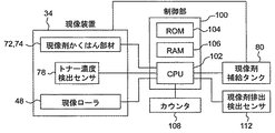
図3は、画像形成装置1の現像装置34に係る制御ブロック図を示している。
FIG. 3 is a control block diagram relating to the developing
制御手段としての制御部100は、CPU(Central Processing Unit)102、ROM(Read Only Memory)104、RAM(Random Access Memory)106等から構成される。ROM104内に格納されている各種処理プログラムやテーブルに従って、CPU102は画像形成装置1での各種動作を集中的に制御する。ROM104には、例えば、トナー濃度検出センサ78で検出された電圧から現像槽内現像剤3のトナー濃度に変換・算出するためのトナー濃度算出テーブルや、現実の現像槽内現像剤3のトナー濃度と第一基準トナー濃度(すなわち第一基準値)との間の差異から補給すべき現像剤量を算出するための現像剤補給用テーブルが格納されている。RAM106は、制御部100により実行される各種プログラム及びこれらプログラムに係るデータを一時的に記憶するワークエリアを形成している。
The
CPU102には、現像装置34や現像剤補給タンク80や現像剤排出検出センサ112やカウンタ108が接続されている。現像装置34を構成する現像剤攪拌部材72,74、トナー濃度検出センサ78、現像ローラ48の動作が、制御部100のCPU102によって制御される。そして、トナー濃度検出センサ78で検出された現像槽内現像剤3のトナー濃度や、画像形成時の画像情報や、現像剤補給タンク80内での補給用現像剤2に対するキャリア比等は、RAM106に一時的に記憶されている。
The
〔現像剤〕
2成分現像剤は、トナーと、トナーを帯電させるためのキャリアと、を含んでいる。本発明においては、画像形成装置1において従来から一般的に使用されている公知のトナーが使用可能である。トナーの粒径は、例えば約3乃至15μmである。バインダー樹脂中に着色剤を含有させたトナーや、荷電制御剤や離型剤を含有するトナーや、表面に添加剤を保持するトナーも使用可能である。
(Developer)
The two-component developer contains toner and a carrier for charging the toner. In the present invention, a known toner that has been generally used in the
トナーは、例えば、粉砕法、乳化重合法、懸濁重合法等の公知の方法で製造される。 The toner is produced by a known method such as a pulverization method, an emulsion polymerization method, or a suspension polymerization method.
トナーに使用されるバインダー樹脂は、限定的ではないが、例えば、スチレン系樹脂(スチレンまたはスチレン置換体を含む単重合体または共重合体)、ポリエステル樹脂、エポキシ系樹脂、塩化ビニル樹脂、フェノール樹脂、ポリエチレン樹脂、ポリプロピレン樹脂、ポリウレタン樹脂、シリコーン樹脂、またはそれらの樹脂を任意に混ぜ合わせたものである。バインダー樹脂は、軟化温度が約80乃至160℃の範囲であり、ガラス転移点が約50乃至75℃の範囲であることが好ましい。 The binder resin used for the toner is not limited. For example, styrene resin (monopolymer or copolymer containing styrene or styrene-substituted product), polyester resin, epoxy resin, vinyl chloride resin, phenol resin. , Polyethylene resin, polypropylene resin, polyurethane resin, silicone resin, or any mixture of these resins. The binder resin preferably has a softening temperature in the range of about 80 to 160 ° C. and a glass transition point in the range of about 50 to 75 ° C.
着色剤は、公知の材料、例えば、カーボンブラック、アニリンブラック、活性炭、マグネタイト、ベンジンイエロー、パーマネントイエロー、ナフトールイエロー、フタロシアニンブルー、ファーストスカイブルー、ウルトラマリンブルー、ローズベンガル、レーキーレッド等を用いることができる。着色剤の添加量は、一般に、バインダー樹脂100重量部に対して、2乃至20重量部であることが好ましい。 For the colorant, a known material such as carbon black, aniline black, activated carbon, magnetite, benzine yellow, permanent yellow, naphthol yellow, phthalocyanine blue, first sky blue, ultramarine blue, rose bengal, lake red, etc. should be used. Can do. In general, the addition amount of the colorant is preferably 2 to 20 parts by weight with respect to 100 parts by weight of the binder resin.
荷電制御剤は、従来から荷電制御剤として知られている材料が使用できる。具体的に、正極性に帯電するトナーには、例えばニグロシン系染料、4級アンモニウム塩系化合物、トリフェニルメタン系化合物、イミダゾール系化合物、ポリアミン樹脂が荷電制御剤として使用できる。負極性に帯電するトナーには、Cr、Co、Al、Fe等の金属含有アゾ系染料、サリチル酸金属化合物、アルキルサリチル酸金属化合物、カーリックスアレーン化合物が荷電制御剤として使用できる。荷電制御剤は、バインダー樹脂100重量部に対して、0.1乃至10重量部の割合で用いることが好ましい。 As the charge control agent, materials conventionally known as charge control agents can be used. Specifically, for the positively charged toner, for example, nigrosine dyes, quaternary ammonium salt compounds, triphenylmethane compounds, imidazole compounds, and polyamine resins can be used as charge control agents. For the negatively charged toner, metal-containing azo dyes such as Cr, Co, Al, and Fe, salicylic acid metal compounds, alkyl salicylic acid metal compounds, and curixarene compounds can be used as charge control agents. The charge control agent is preferably used at a ratio of 0.1 to 10 parts by weight with respect to 100 parts by weight of the binder resin.
離型剤は、従来から離型剤として使用されている公知のものを使用できる。離型剤の材料には、例えば、ポリエチレン、ポリプロピレン、カルナバワックス、サゾールワックス、又はそれらを適宜組み合わせた混合物が用いられる。離型剤は、バインダー樹脂100重量部に対して、0.1乃至10重量部の割合で用いることが好ましい。 As the release agent, a known release agent conventionally used as a release agent can be used. As the material for the release agent, for example, polyethylene, polypropylene, carnauba wax, sazol wax, or a mixture of them as appropriate is used. The release agent is preferably used at a ratio of 0.1 to 10 parts by weight with respect to 100 parts by weight of the binder resin.
さらに、現像剤の流動化を促進する流動化剤を添加してもよい。流動化剤には、例えば、シリカ、酸化チタン、酸化アルミニウム等の無機微粒子や、アクリル樹脂、スチレン樹脂、シリコーン樹脂、フッ素樹脂等の樹脂微粒子が使用できる。特にシランカップリング剤、チタンカップリング剤、およびシリコンオイル等で疎水化した材料を用いるのが好ましい。流動化剤は、トナー100重量部に対して、0.1乃至5重量部の割合で添加することが好ましい。これら添加剤の個数平均一次粒径は、9乃至100nmであることが好ましい。 Furthermore, a fluidizing agent that promotes fluidization of the developer may be added. As the fluidizing agent, for example, inorganic fine particles such as silica, titanium oxide, and aluminum oxide, and resin fine particles such as acrylic resin, styrene resin, silicone resin, and fluorine resin can be used. In particular, it is preferable to use a material hydrophobized with a silane coupling agent, a titanium coupling agent, silicon oil or the like. The fluidizing agent is preferably added at a ratio of 0.1 to 5 parts by weight with respect to 100 parts by weight of the toner. The number average primary particle size of these additives is preferably 9 to 100 nm.
キャリアは、従来から一般に使用されている公知のキャリアを使用できる。バインダー型キャリアやコート型キャリアのいずれを用いてもよい。キャリア粒径は、限定的ではないが、約15乃至100μmであることが好ましい。 As the carrier, a known carrier that has been generally used can be used. Either a binder type carrier or a coat type carrier may be used. The carrier particle size is not limited, but is preferably about 15 to 100 μm.
バインダー型キャリアは、磁性体微粒子をバインダー樹脂中に分散させたものであり、表面に正極性または負極性に帯電する微粒子又はコーティング層を有するものが使用できる。バインダー型キャリアの極性等の帯電特性は、バインダー樹脂の材質、帯電性微粒子、表面コーティング層の種類によって制御できる。 The binder type carrier is obtained by dispersing magnetic fine particles in a binder resin, and those having fine particles or a coating layer charged positively or negatively on the surface can be used. The charging characteristics such as the polarity of the binder type carrier can be controlled by the material of the binder resin, the chargeable fine particles, and the type of the surface coating layer.
バインダー型キャリアに用いられるバインダー樹脂としては、ポリスチレン系樹脂に代表されるビニル系樹脂、ポリエステル系樹脂、ナイロン系樹脂、ポリオレフィン系樹脂などの熱可塑性樹脂、フェノール樹脂等の硬化性樹脂が例示される。 Examples of the binder resin used for the binder-type carrier include thermoplastic resins such as vinyl resins, polyester resins, nylon resins, polyolefin resins, and the like typified by polystyrene resins, and curable resins such as phenol resins. .
バインダー型キャリアの磁性体微粒子としては、マグネタイト、ガンマ酸化鉄等のスピネルフェライト、鉄以外の金属(Mn、Ni、Mg、Cu等)を一種または二種以上含有するスピネルフェライト、バリウムフェライト等のマグネトプランバイト型フェライト、表面に酸化層を有する鉄や合金の粒子を用いることができる。キャリアの形状は、粒状、球状、針状のいずれであってもよい。特に高磁化を要する場合には、鉄系の強磁性微粒子を用いることが好ましい。化学的な安定性を考慮すると、マグネタイト、ガンマ酸化鉄を含むスピネルフェライトやバリウムフェライト等のマグネトプランバイト型フェライトの強磁性微粒子を用いることが好ましい。強磁性微粒子の種類及び含有量を適宜選択することにより、所望の磁化を有する磁性樹脂キャリアを得ることができる。磁性体微粒子は磁性樹脂キャリア中に50乃至90重量%の量で添加することが適切である。 Magnetic fine particles of the binder type carrier include spinel ferrite such as magnetite and gamma iron oxide, and magnets such as spinel ferrite and barium ferrite containing one or more metals other than iron (Mn, Ni, Mg, Cu, etc.). Plumbite type ferrite, iron or alloy particles having an oxide layer on the surface can be used. The shape of the carrier may be granular, spherical, or needle-shaped. In particular, when high magnetization is required, it is preferable to use iron-based ferromagnetic fine particles. In consideration of chemical stability, it is preferable to use ferromagnetic fine particles of magnetoplumbite type ferrite such as spinel ferrite and barium ferrite containing magnetite and gamma iron oxide. A magnetic resin carrier having a desired magnetization can be obtained by appropriately selecting the type and content of the ferromagnetic fine particles. The magnetic fine particles are suitably added in an amount of 50 to 90% by weight in the magnetic resin carrier.
バインダー型キャリアの表面コート材としては、シリコーン樹脂、アクリル樹脂、エポキシ樹脂、フッ素系樹脂等が用いられる。これらの樹脂をキャリア表面にコートし硬化させてコート層を形成することにより、キャリアの電荷付与能力を向上できる。 Silicone resin, acrylic resin, epoxy resin, fluorine resin, etc. are used as the surface coating material for the binder type carrier. The charge imparting ability of the carrier can be improved by coating and curing these resins on the carrier surface to form a coat layer.
バインダー型キャリアの表面への帯電性微粒子あるいは導電性微粒子の固着は、例えば、磁性樹脂キャリアと微粒子とを均一混合し、磁性樹脂キャリアの表面にこれら微粒子を付着させた後、機械的・熱的な衝撃力を与えることにより微粒子を磁性樹脂キャリア中に打ち込むことで行われる。この場合、微粒子は、磁性樹脂キャリア中に完全に埋設されるのではなく、その一部が磁性樹脂キャリア表面から突出するように固定される。帯電性微粒子には、有機、無機の絶縁性材料が用いられる。具体的に、有機系の絶縁性材料としては、ポリスチレン、スチレン系共重合物、アクリル樹脂、各種アクリル共重合物、ナイロン、ポリエチレン、ポリプロピレン、フッ素樹脂およびこれらの架橋物などの有機絶縁性微粒子がある。電荷付与能力および帯電極性は、帯電性微粒子の素材、重合触媒、表面処理等に調整できる。無機系の絶縁性材料としては、シリカ、二酸化チタン等の負極性に帯電する無機微粒子や、チタン酸ストロンチウム、アルミナ等の正極性に帯電する無機微粒子が用いられる。 For example, the charging fine particles or the conductive fine particles can be fixed to the surface of the binder type carrier by, for example, mixing the magnetic resin carrier and the fine particles uniformly and adhering the fine particles to the surface of the magnetic resin carrier. This is done by driving fine particles into the magnetic resin carrier by applying a strong impact force. In this case, the fine particles are not completely embedded in the magnetic resin carrier, but are fixed so that a part thereof protrudes from the surface of the magnetic resin carrier. Organic and inorganic insulating materials are used for the chargeable fine particles. Specifically, organic insulating materials include polystyrene, styrene-based copolymers, acrylic resins, various acrylic copolymers, nylon, polyethylene, polypropylene, fluororesin, and cross-linked products thereof such as organic insulating fine particles. is there. The charge imparting ability and the charge polarity can be adjusted to the material of the chargeable fine particles, the polymerization catalyst, the surface treatment and the like. As the inorganic insulating material, negatively charged inorganic fine particles such as silica and titanium dioxide, and positively charged inorganic fine particles such as strontium titanate and alumina are used.
コート型キャリアは、磁性体からなるキャリアコア粒子を樹脂で被覆したキャリアであり、バインダー型キャリア同様に、キャリア表面に正極性または負極性に帯電する帯電性微粒子を固着することができる。コート型キャリアの極性等の帯電特性は、表面コーティング層の種類や帯電性微粒子の選択により調整できる。コーティング樹脂は、バインダー型キャリアのバインダー樹脂と同様の樹脂が使用可能である。 The coat type carrier is a carrier in which carrier core particles made of a magnetic material are coated with a resin, and like the binder type carrier, chargeable fine particles that are charged positively or negatively can be fixed to the surface of the carrier. The charging characteristics such as the polarity of the coated carrier can be adjusted by selecting the type of the surface coating layer and the electrifying fine particles. As the coating resin, the same resin as the binder resin of the binder type carrier can be used.
現像槽内現像剤3のトナー及びキャリアの混合比は、所望のトナー帯電量が得られるように調整される。現像槽内現像剤3のトナー比は、トナー及びキャリアの合計量に対して、好ましくは3乃至20重量%であり、より好ましくは4乃至15重量%である。また、現像剤補給タンク80に充填されている補給用現像剤2は、トナー及び少量のキャリアを含有したものであり、補給用現像剤2のキャリア比は、好ましくは1乃至50重量%であり、より好ましくは5乃至30重量%である。
The mixing ratio of the toner and the carrier in the
このように構成された現像装置34の動作を説明する。
The operation of the developing
画像形成時、図示しないモータの駆動に基づいて、現像ローラ48のスリーブ48bは矢印方向(反時計回り)に回転する。第一スクリュー72の回転及び第二スクリュー74の回転により、現像剤攪拌搬送室67に存する現像槽内現像剤3は、第一搬送路68と第二搬送路70とを循環搬送されながら、攪拌される。その結果、現像剤に含まれるトナーとキャリアとが摩擦接触し、互いに逆の極性に帯電される。実施形態では、キャリアは正極性、トナーは負極性に帯電されるものとする。本発明に用いるトナー及びキャリアの帯電性は、このような組み合わせに限定されるものでない。キャリアの外形寸法は、トナーに比べて相当大きい。そのため、正極性に帯電したキャリアの周囲に、負極性に帯電したトナーが、主として両者の電気的な吸引力に基づいて付着している。
During image formation, the
帯電された現像槽内現像剤3は、第二スクリュー74によって第二搬送路70に搬送される過程で現像ローラ48に供給される。この現像剤は、現像ローラ48内部の磁石体48aの磁力によってスリーブ48bの表面側に保持され、スリーブ48bと共に反時計周り方向に回転移動して、現像ローラ48に対向して設けられた規制板62で通過量を規制された後、感光体12と対向する現像領域へと搬送される。そして、現像領域において、磁石体48aの主磁極N1の磁力によって穂立ち(磁気ブラシ)が形成される。現像領域では、感光体12上の静電潜像と現像バイアスの印加された現像ローラ48との間に形成された電界(直流に交流が重畳された電界)がトナーに与える力により、トナーが感光体12上の静電潜像側へと移動して、この静電潜像が顕像へと現像される。現像領域でトナーを消費した現像剤は、現像槽66に向けて搬送され、現像槽66の第二搬送路70に対向して設けられた磁石体48aのN3,N2の反発磁界によって現像ローラ48上から剥離され、現像槽66内へと回収される。回収された現像剤は、第二搬送路70を搬送されている現像槽内現像剤3と混合される。
The charged
このような画像形成によって現像槽内現像剤3の中からトナーが強制消費されると、消費された量に見合う量のトナーが現像槽内現像剤3に補給されることが好ましい。そのために、現像装置34は、現像剤攪拌搬送室67に存する現像槽内現像剤3に対するトナーの比を測定するトナー濃度検出センサ78を備えている。また、第一搬送路68の上方には現像剤補給タンク80が設けてある。
When the toner is forcibly consumed from the
本発明における画像形成には、大別すると、現像後に紙出力を伴う一般の画像形成と、現像後に紙出力を行わないいわゆるパッチ画像形成と、がある。パッチ画像形成とは、画像データに基づいて露光装置28の画像光30を照射状態/非照射状態に切り替えるのではなく、露光装置28の画像光30を所定光量で照射状態を続けることにより感光体12上にベタ状態の静電潜像を形成することを意味している。ベタ状態の静電潜像を現像することによりトナーを感光体12上に強制的に付着させ、強制的に付着させたトナーを用紙38に転写することなくクリーニング装置40で回収することによりトナーが強制的に消費される。トナーの強制消費動作のために一般の画像形成を行うと、用紙38を無駄に消費してしまうので、本発明においては、トナーの強制消費動作のために、パッチ画像形成が用いられる。さらに、トナーの強制消費動作の際に、一回のパッチ画像形成によってできるだけ多くのトナーを消費させるために、パッチ画像形成は、感光体12のできるだけ広い領域に画像光30が照射されるものであることが好適である。
The image formation in the present invention can be broadly classified into general image formation accompanied by paper output after development and so-called patch image formation in which paper output is not performed after development. In the patch image formation, the
次に、第一実施形態に係る現像装置34の動作を、図4及び5を参照しながら説明する。
Next, the operation of the developing
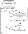
図4は、本発明の一実施形態に係る現像装置34の補給動作のメインフローチャートを示している。図5は、第一実施形態に係る第一のトナー強制消費モードのフローチャートを示している。なお、第一実施形態に係る第一のトナー強制消費モードに関する理解を助けるために、以下のような具体的な数値を提示しながら説明するが、当該数値によって本実施形態が限定されるものではなく、単なる一例として提示した数値に過ぎない。
FIG. 4 shows a main flowchart of the replenishment operation of the developing
トリクル方式の現像装置34において貯蔵される現像槽内現像剤3の第一基準トナー濃度(すなわち第一基準値)は7重量%であり、その量は約250gである。現像装置34内の現像槽内現像剤3の第二基準トナー濃度(すなわち第二基準値)は、第一基準トナー濃度(7重量%)+2重量%とすると、9重量%である。現像装置34内において第二基準トナー濃度(9重量%)で貯蔵される現像剤の量は、約210gである。一回のパッチ画像形成によって消費されるトナー量は、約0.5gである。補給用現像剤2のキャリア比は、15重量%である。一回の補給用現像剤2の補給量は、約0.6gであり、トナー量に換算すれば約0.5gである。補給用現像剤2の補給回数Kは、100回である。
The first reference toner concentration (that is, the first reference value) of the
図4は、図示しない全体制御(メインルーチン)のうちの現像装置34の補給制御に関するサブルーチンを示している。ステップS12において、トナー濃度検出センサ78によって、現像剤攪拌搬送室67に存する現像槽内現像剤3のトナー濃度に関する電圧信号が出力される。ステップS14において、出力された電圧信号は、制御部100でトナー濃度の値に変換・算出される。ステップS20において、現状のトナー濃度が第一基準トナー濃度(7重量%)よりも低いか否かが判別される。現状のトナー濃度が第一基準トナー濃度よりも低いと判別された場合、ステップS22において、トナー濃度検出センサ78によって検出された現状のトナー濃度と、画像形成時の画像情報(ドットカウンタ)と、現像剤補給タンク80内での補給用現像剤2に対するキャリア比と、に基づいて、補給用現像剤2の補給量が算出される。そして、ステップS24において、所定量の補給用現像剤2が補給されたあと、ステップS12のトナー濃度検出に戻る。
FIG. 4 shows a subroutine related to replenishment control of the developing
ステップS20において、現状のトナー濃度が第一基準トナー濃度以上であると判別された場合、ステップS30において、現状のトナー濃度が第二基準トナー濃度(9重量%)よりも低いか否かが判別される。現状のトナー濃度が第二基準トナー濃度(9重量%)よりも低いと判別された場合、当該サブルーチンが終了してメインルーチンに戻る。トナー濃度検出センサ78の測定精度や、トナー濃度検出センサ78周辺での現像槽内現像剤3の充填状態や、画像形成装置の周囲環境の変動によって、現状のトナー濃度が第二基準トナー濃度(9重量%)以上であると判別された場合、ステップS40において、第一のトナー強制消費モードに移行する。このとき、現像装置34内において貯蔵される現像槽内現像剤3の量は、約210gである。
If it is determined in step S20 that the current toner concentration is equal to or higher than the first reference toner concentration, it is determined in step S30 whether or not the current toner concentration is lower than the second reference toner concentration (9% by weight). Is done. If it is determined that the current toner density is lower than the second reference toner density (9% by weight), the subroutine ends and returns to the main routine. Depending on the measurement accuracy of the toner
図5は、図4の現像装置34の補給制御に関するサブルーチンのうちの第一のトナー強制消費モードに関するサブルーチンを示している。ステップS112において、補給用現像剤2を何回補給するかという補給回数K(100回)が設定される。ステップS114において、トナーの強制消費動作のために、現像後に紙出力を行わないパッチ画像形成が行われる。このパッチ画像形成は、一回のパッチ画像形成によってできるだけ多くのトナーを消費させるために、大略全面に画像が形成されるベタ状態である。一回のパッチ画像形成によって、約0.5gのトナーが消費される。
FIG. 5 shows a subroutine related to the first toner forced consumption mode among the subroutines related to the replenishment control of the developing
所定回数(100回)の補給が行われていないと判別された場合、ステップS124において、トナー濃度検出センサ78によって、現像剤攪拌搬送室67に存する現像槽内現像剤3のトナー濃度に関する電圧信号が出力される。ステップS126において、出力された電圧信号は、制御部100でトナー濃度の値に変換・算出される。ステップS130において、検出された現状の現像槽内現像剤3のトナー濃度が第一基準トナー濃度(7重量%)よりも低いか否かが判別される。
If it is determined that the predetermined number (100 times) of replenishment has not been performed, in step S124, the toner
ステップS130において、現状の現像槽内現像剤3のトナー濃度が第一基準トナー濃度(7重量%)以上であると判別された場合、ステップS114のパッチ画像形成に戻る。すなわち、現状のトナー濃度が第一基準トナー濃度(7重量%)より低くなるまで、ステップS114のパッチ画像形成を繰り返す。例えば、10数回のパッチ画像形成が繰り返される。パッチ画像形成を繰り返すことでトナーが消費されてトナー濃度が次第に低下するが、補給用現像剤2の補給動作が無いために、現像槽66内での現像槽内現像剤3の嵩レベルが低下している。
If it is determined in step S130 that the current toner density of the
パッチ画像形成を繰り返した結果、ステップS130において、現状の現像槽内現像剤3のトナー濃度が第一基準トナー濃度(7重量%)を下回った、言い換えると現状の現像槽内現像剤3のトナー濃度が第一基準トナー濃度に回復したと判別された場合、ステップS132において、トナー濃度検出センサ78によって検出された現状の現像槽内現像剤3のトナー濃度と、画像形成時の画像情報(ドットカウンタ)と、現像剤補給タンク80内での補給用現像剤2に対するキャリア比と、に基づいて、補給用現像剤2の補給量が算出される。そして、ステップS134において、補給用現像剤2が算出された量(約0.6g)で補給されたあと、ステップS136において、ルーチンの回数を一つ減らし、ステップS114のパッチ画像形成に戻る。ステップS114のパッチ画像形成によってトナーが消費されるが、トナーの補給量(約0.5g)と消費量(約0.5g)とがつり合っているために、現像槽内現像剤3のトナー濃度は第一基準トナー濃度(7重量%)に回復した状態を維持している。その結果、ステップS130において、実質的には、現状の現像槽内現像剤3のトナー濃度が第一基準トナー濃度(7重量%)を下回ったと判別される方(YES)に行くことになる。したがって、ステップS114のパッチ画像形成によるトナー消費動作に加えて、ステップS134乃至S136の補給用現像剤2の補給動作が繰り返される。このことは、現状の現像槽内現像剤3のトナー濃度が第一基準トナー濃度(7重量%)に回復しつつ、補給用現像剤2に含まれるキャリアの補給を行っていること、言い換えれば、キャリアが補給されるにつれて、現像槽66内での現像槽内現像剤3の嵩レベルが次第に上昇することを意味している。
As a result of repeating the patch image formation, in step S130, the toner density of the current
ステップS120において、所定回数(100回)の補給が行われたかが判別される。所定回数(100回)の補給が行われたと判別された場合、第一のトナー強制消費モードに関するサブルーチンが終了して、図4の現像装置34の補給制御に関するサブルーチンに戻る。
In step S120, it is determined whether a predetermined number of times (100 times) of replenishment has been performed. If it is determined that the predetermined number of times (100 times) of replenishment has been performed, the subroutine relating to the first toner forced consumption mode ends, and the process returns to the subroutine relating to the replenishment control of the developing
第一のトナー強制消費モードによれば、補給用現像剤2の補給動作において、現像槽内現像剤3のトナー濃度及び嵩レベルの正確さと補給に要する時間とがバランス良い。
According to the first toner forced consumption mode, in the replenishment operation of the
このような第一のトナー強制消費モードを有する画像形成装置1で一般の画像形成を行ったが、スクリュームラ等の画像欠損が発生することは無く、第一のトナー強制消費モードの効果が確認された。
General image formation was performed with the
次に、第二実施形態に係る現像装置34の動作を、図6を参照しながら説明する。
Next, the operation of the developing
図6は、第二実施形態に係る第二のトナー強制消費モードに関するサブルーチンのフローチャートを示している。なお、第二実施形態に係る第二のトナー強制消費モードに関する理解を助けるために、以下のような具体的な数値を提示しながら説明するが、当該数値によって本実施形態が限定されるものではなく、単なる一例として提示した数値に過ぎない。 FIG. 6 shows a flowchart of a subroutine related to the second toner forced consumption mode according to the second embodiment. In order to assist understanding of the second toner forced consumption mode according to the second embodiment, the following specific numerical values are presented for explanation, but the present embodiment is not limited by the numerical values. It is just a numerical value presented as an example.
トリクル方式の現像装置34において貯蔵される現像槽内現像剤3の第一基準トナー濃度は7重量%であり、その量は約250gである。現像装置34内の現像槽内現像剤3の第二基準トナー濃度は、第一基準トナー濃度(7重量%)+2重量%とすると、9重量%である。現像装置34内において第二基準トナー濃度(9重量%)で貯蔵される現像剤の量は、約210gである。一回のパッチ画像形成によって消費されるトナー量は、約0.5gである。補給用現像剤2のキャリア比は、15重量%である。一回の補給用現像剤2の補給量は、約0.6gであり、トナー量に換算すれば約0.5gである。画像形成の回数Mは、100回である。補給開始の回数Lは、5回である。
The first reference toner concentration of the
第二実施形態において、現像装置34の補給制御に関するサブルーチンは、上述した第一実施形態のものと同じであるためにその説明を省略し、第一実施形態のものと異なっている第二のトナー強制消費モードに関するサブルーチンについてのみ説明する。
In the second embodiment, the subroutine relating to the replenishment control of the developing
図6は、図4の現像装置34の補給制御に関するサブルーチンのうちの第二のトナー強制消費モードに関するサブルーチンを示している。ステップS212において、画像形成を何回行うかという画像形成回数M(100回)と、何回画像形成を行ったあとに補給を開始するかという補給開始回数L(例えば、5回)が設定される。ステップS214において、トナーの強制消費動作のために、現像後に紙出力を行わないパッチ画像形成が行われる。このパッチ画像形成は、一回のパッチ画像形成によってできるだけ多くのトナーを消費させるために、大略全面に画像が形成されるベタ状態である。一回のパッチ画像形成によって、約0.5gのトナーが消費される。ステップS220において、所定回数(100回)の画像形成が行われたか否かが判別される。
FIG. 6 shows a subroutine related to the second toner forced consumption mode among the subroutines related to the replenishment control of the developing
ステップS220において、所定回数(100回)の画像形成が行われていないと判別された場合、ステップS240に進んで、所定回数の画像形成を行って所定の補給開始回数(100−5=95回)になっているか否かが判別される。ステップS240において、所定の補給開始回数になっていないと判別された場合、ステップS244において、ルーチンの数を一つ減らして、ステップS214のパッチ画像形成に戻る。上記設定条件によれば、5回の画像形成を繰り返すと95回の補給開始回数になるので、ステップS240において、所定の補給開始回数になっていると判別される。 If it is determined in step S220 that the predetermined number of times (100 times) of image formation has not been performed, the process proceeds to step S240, where the predetermined number of times of image formation is performed and the predetermined number of replenishment start times (100-5 = 95 times). ) Is determined. If it is determined in step S240 that the predetermined number of supply start times has not been reached, the number of routines is reduced by one in step S244, and the process returns to patch image formation in step S214. According to the above setting condition, if the image formation is repeated five times, the number of replenishment starts is 95. Therefore, in step S240, it is determined that the predetermined number of replenishment starts.
ステップS240において、所定の補給開始回数になっていると判別された場合、ステップS242において、所定量(約0.6g)の補給用現像剤2が補給される。そのあと、ステップS244において、ルーチンの回数を一つ減らし、ステップS214のパッチ画像形成に戻る。ステップS214のパッチ画像形成によってトナーが消費されるが、トナーの補給量(約0.5g)と消費量(約0.5g)とがつり合っているために、現像槽内現像剤3のトナー濃度は大略5回の画像形成の分だけ低くなった状態を維持している。
If it is determined in step S240 that the predetermined number of replenishment start times has been reached, a predetermined amount (about 0.6 g) of
トータルで100回の画像形成を行うと、ステップS220において、所定回数の画像形成が行われたと判別されるので、ステップS222において、トナー濃度検出センサ78によって、現像剤攪拌搬送室67に存する現像槽内現像剤3のトナー濃度に関する電圧信号が出力される。ステップS224において、出力された電圧信号は、制御部100で現像槽内現像剤3のトナー濃度の値に変換・算出される。ステップS230において、検出された現状の現像槽内現像剤3のトナー濃度が第二基準トナー濃度(9重量%)よりも低いか否かが判別される。
When the image formation is performed 100 times in total, it is determined in step S220 that the predetermined number of image formations have been performed. Therefore, in step S222, the developing tank existing in the developer stirring and conveying
ステップS230において、現状の現像槽内現像剤3のトナー濃度が第二基準トナー濃度(9重量%)以上であると判別された場合、ステップS214のパッチ画像形成に戻る。すなわち、現状の現像槽内現像剤3のトナー濃度が第二基準トナー濃度(9重量%)より低くなるまで、ステップS214のパッチ画像形成を繰り返す。パッチ画像形成を繰り返すことでトナーが消費されて現像槽内現像剤3のトナー濃度が次第に低下するが、補給用現像剤2の補給動作が無いために、現像槽66内での現像槽内現像剤3の嵩レベルが低下している。
If it is determined in step S230 that the current toner density of the
ステップS230において、現状の現像槽内現像剤3のトナー濃度が第二基準トナー濃度(9重量%)より低くなったと判別された場合、第二のトナー強制消費モードに関するサブルーチンが終了して、図4の現像装置34の補給制御に関するサブルーチンに戻る。
If it is determined in step S230 that the current toner density of the
第二のトナー強制消費モードによれば、現像槽内現像剤3のトナー濃度を第二基準トナー濃度で規定し、現像槽内現像剤3の嵩レベルを補給開始回数で規定しているために現像槽内現像剤3のトナー濃度及び嵩レベルの精度が低くなるが、補給用現像剤2の補給に要する時間を大幅に短縮することができるという特徴を有している。
According to the second toner forced consumption mode, the toner density of the
このような第二のトナー強制消費モードを有する画像形成装置1で一般の画像形成を行ったが、スクリュームラ等の画像欠損が発生することは無く、第二のトナー強制消費モードの効果が確認された。
General image formation was performed with the
次に、第三実施形態に係る現像装置34の動作を、図7を参照しながら説明する。
Next, the operation of the developing
図7は、第三実施形態に係る第三のトナー強制消費モードに関するサブルーチンのフローチャートを示している。なお、第三実施形態に係る第三のトナー強制消費モードに関する理解を助けるために、以下のような具体的な数値を提示しながら説明するが、当該数値によって本実施形態が限定されるものではなく、単なる一例として提示した数値に過ぎない。 FIG. 7 shows a flowchart of a subroutine relating to the third toner forced consumption mode according to the third embodiment. In order to facilitate understanding of the third toner forced consumption mode according to the third embodiment, the following specific numerical values will be presented, but the present embodiment is not limited by the numerical values. It is just a numerical value presented as an example.
トリクル方式の現像装置34において貯蔵される現像槽内現像剤3の第一基準トナー濃度は7重量%であり、その量は約250gである。現像装置34内の現像槽内現像剤3の第二基準トナー濃度は、第一基準トナー濃度(7重量%)+2重量%とすると、9重量%である。現像装置34内において第二基準トナー濃度(9重量%)で貯蔵される現像槽内現像剤3の量は、約210gである。一回のパッチ画像形成によって消費されるトナー量は、約0.5gである。補給用現像剤2のキャリア比は、15重量%である。一回の補給用現像剤2の補給量は、約0.6gであり、トナー量に換算すれば約0.5gである。
The first reference toner concentration of the
第三実施形態において、現像装置34の補給制御に関するサブルーチンは、上述した第一実施形態のものと同じであるためにその説明を省略し、第一実施形態のものと異なっている第三のトナー強制消費モードに関するサブルーチンについてのみ説明する。
In the third embodiment, the subroutine relating to the replenishment control of the developing
図7は、図4の現像装置34の補給制御に関するサブルーチンのうちの第三のトナー強制消費モードに関するサブルーチンを示している。ステップS312において、トナーの強制消費動作のために、現像後に紙出力を行わないパッチ画像形成が行われる。このパッチ画像形成は、一回のパッチ画像形成によってできるだけ多くのトナーを消費させるために、大略全面に画像が形成されるベタ状態である。一回のパッチ画像形成によって、約0.5gのトナーが消費される。
FIG. 7 shows a subroutine related to the third toner forced consumption mode among the subroutines related to the replenishment control of the developing
ステップS314において、トナー濃度検出センサ78によって、現像剤攪拌搬送室67に存する現像槽内現像剤3のトナー濃度に関する電圧信号が出力される。ステップS316において、出力された電圧信号は、制御部100で現像槽内現像剤3のトナー濃度の値に変換・算出される。ステップS320において、検出された現状の現像槽内現像剤3のトナー濃度が第一基準トナー濃度(7重量%)よりも低いか否かが判別される。
In step S <b> 314, the toner
ステップS330において、現状の現像槽内現像剤3のトナー濃度が第一基準トナー濃度(7重量%)以上であると判別された場合、ステップS312のパッチ画像形成に戻る。すなわち、現状の現像槽内現像剤3のトナー濃度が第一基準トナー濃度(7重量%)より低くなるまで、ステップS312のパッチ画像形成を繰り返す。パッチ画像形成を繰り返すことでトナーが消費されて現像槽内現像剤3のトナー濃度が次第に低下するが、補給用現像剤2の補給動作が無いために、現像槽66内での現像槽内現像剤3の嵩レベルが低下している。
If it is determined in step S330 that the current toner density of the
パッチ画像形成を繰り返した結果、ステップS320において、現状の現像槽内現像剤3のトナー濃度が第一基準トナー濃度(7重量%)を下回った、言い換えれば現状の現像槽内現像剤3のトナー濃度が第一基準トナー濃度に回復したと判別された場合、ステップS322において、現状の現像槽内現像剤3のトナー濃度に基づいて補給用現像剤2の補給量が算出される。そして、ステップS324において、所定量(約0.6g)の補給用現像剤2が補給されたあと、ステップS330において、現像剤排出検出センサ112によって、現像槽内現像剤3が現像剤回収タンク90に排出されたか否かが判別される。
As a result of repeating the patch image formation, in step S320, the toner density of the current
ステップS330において、現像槽内現像剤3が現像剤回収タンク90に排出されていないと判別された場合、ステップS312のパッチ画像形成に戻る。
If it is determined in step S330 that the
ステップS312のパッチ画像形成によってトナーが消費されるが、トナーの補給量(約0.5g)と消費量(約0.5g)とがつり合っているために、現像槽内現像剤3のトナー濃度は、第一基準トナー濃度(7重量%)に回復した状態を維持している。その結果、ステップS320において、実質的には、現状の現像槽内現像剤3のトナー濃度が第一基準トナー濃度(7重量%)を下回ったと判別される方(YES)に行くことになる。したがって、ステップS312のパッチ画像形成によるトナー消費動作に加えて、ステップS322乃至S330の補給用現像剤2の補給動作及び現像槽内現像剤3の排出検出が繰り返される。このことは、現状の現像槽内現像剤3のトナー濃度が第一基準トナー濃度(7重量%)に回復しつつ、補給用現像剤2の補給すなわちキャリアの補給を行っていること、言い換えれば、キャリアが補給されるにつれて、現像槽66内での現像槽内現像剤3の嵩レベルが次第に上昇することを意味している。
The toner is consumed by the patch image formation in step S312, but since the toner replenishment amount (about 0.5 g) and the consumption amount (about 0.5 g) are balanced, the toner in the
ステップS330において、現像槽内現像剤3が現像剤回収タンク90に排出されたと判別された場合、現像剤攪拌搬送室67内の現像槽内現像剤3が流出口から流出して現像剤回収タンク90に現に落下して現像槽内現像剤3の嵩レベルが基準嵩レベルまで回復したことを意味するので、ステップS332において、第三のトナー強制消費モードが終了する。
In step S330, when it is determined that the
第三のトナー強制消費モードによれば、補給用現像剤2の補給動作において、現像槽内現像剤3のトナー濃度及び嵩レベルを所定値まで精度良く回復させることができる。第三のトナー強制消費モードは、現像槽内現像剤3の嵩レベルが所定の基準嵩レベルに回復するまで補給用現像剤2が補給されて多くの補給用現像剤2を必要とすることから、現像装置34の現像槽66が小型である場合に好適である。
According to the third toner forced consumption mode, in the replenishment operation of the
このような第三のトナー強制消費モードを有する画像形成装置1で一般の画像形成を行ったが、スクリュームラ等の画像欠損が発生することは無く、第三のトナー強制消費モードの効果が確認された。
General image formation was performed with the
なお、上記各実施形態においては、具体的な数値を用いながら説明したが、当該数値によって本願発明が限定されるものではなく、特許請求の範囲及び均等物によって画定される範囲を逸脱しない範囲で本願発明を様々に変形させることができる。 In each of the above embodiments, the description has been made using specific numerical values, but the present invention is not limited by the numerical values, and is within a range not departing from the scope defined by the claims and equivalents. The present invention can be variously modified.
1:画像形成装置
2:補給用現像剤
3:現像槽内現像剤
12:感光体
20:定着装置
22:定着ローラ
26:帯電装置
28:露光装置
30:画像光
34:現像装置
36:転写装置
38:用紙
40:クリーニング装置
48:現像ローラ(現像剤担持体)
48a:磁石体
48b:スリーブ
62:規制板
66:現像槽
67:現像剤攪拌搬送室
68:第一搬送路
70:第二搬送路
72:第一スクリュー(攪拌部材)
74:第二スクリュー(攪拌部材)
75:切欠(流出口)
76:隔壁
77:逆羽根部
78:トナー濃度検出センサ
80:現像剤補給タンク
82:補給口
90:現像剤回収タンク
92:回収口
100:制御部
102:中央演算処理装置(CPU)
104:読み出し専用メモリ(ROM)
106:読み書き可能メモリ(RAM)
108:カウンタ
112:現像剤排出検出センサ
DESCRIPTION OF SYMBOLS 1: Image forming device 2: Developer for replenishment 3: Developer in developing tank 12: Photoconductor 20: Fixing device 22: Fixing roller 26: Charging device 28: Exposure device 30: Image light 34: Developing device 36: Transfer device 38: Paper 40: Cleaning device 48: Developing roller (developer carrier)
48a:
74: Second screw (stirring member)
75: Notch (outlet)
76: partition wall 77: reverse blade portion 78: toner concentration detection sensor 80: developer supply tank 82: supply port 90: developer recovery tank 92: recovery port 100: control unit 102: central processing unit (CPU)
104: Read-only memory (ROM)
106: Read / write memory (RAM)
108: Counter 112: Developer discharge detection sensor
Claims (11)
トナー及びキャリアを含有する補給用現像剤を現像槽へ補給する現像剤補給タンクと、
前記現像槽内の現像剤に含まれるトナーの比率であるトナー濃度を検出するトナー濃度検出センサと、
前記現像槽に設けられ、現像槽内の現像槽内現像剤の量が所定量を上回ったときに、上回った現像槽内現像剤を現像槽外に排出する排出機構と、
前記現像槽内のトナー濃度が第一基準値よりも低いと検出されたときに補給用現像剤の補給動作を行い、前記現像槽内のトナー濃度が第一基準値よりも高い第二基準値よりも高いと検出されたときに現像槽内のトナーの強制消費動作及び補給用現像剤の補給動作を行う制御手段と、
を備えることを特徴とする現像装置。 An agitating member for agitating the developer in the developing tank containing the toner and the carrier while being conveyed in the developing tank, and development for supplying the agitated developer in the developing tank adjacent to the agitating member to the electrostatic latent image carrier. A developing device comprising an agent carrier,
A developer replenishment tank for replenishing a developer tank with a replenishment developer containing toner and a carrier;
A toner concentration detecting sensor for detecting the toner density is the ratio of toner contained in the developer of the developer tank,
A discharge mechanism that is provided in the developing tank and discharges the developer in the developing tank that has exceeded the amount outside the developing tank when the amount of the developer in the developing tank exceeds a predetermined amount;
When it is detected that the toner concentration in the developing tank is lower than the first reference value, the replenishment developer is replenished, and the second reference value in which the toner concentration in the developing tank is higher than the first reference value Control means for performing a forced toner consumption operation and a replenishment developer replenishment operation when it is detected that
A developing device comprising:
前記制御手段は、現像槽内のトナー濃度が第二基準値よりも高いと検出されたときに現像槽内現像剤の排出が検出されるまでの間現像槽内のトナーの強制消費動作及び補給用現像剤の補給動作を並行して行うことを特徴とする、請求項1乃至3のいずれかに記載の現像装置。 The developing device further includes a developer discharge detection sensor that detects whether or not the developer in the developing tank is discharged from the discharge mechanism,
The control means forcibly consumes and replenishes the toner in the developing tank until it is detected that the developer in the developing tank is discharged when it is detected that the toner concentration in the developing tank is higher than the second reference value. 4. The developing device according to claim 1, wherein the developer is replenished in parallel.
トナー及びキャリアを含有する補給用現像剤を現像槽へ補給する現像剤補給タンクと、
前記現像槽内の現像剤に含まれるトナーの比率であるトナー濃度を検出するトナー濃度検出センサと、
前記現像槽に設けられ、現像槽内の現像槽内現像剤の量が所定量を上回ったときに、上回った現像槽内現像剤を現像槽外に排出する排出機構と、
前記現像槽内のトナー濃度が第一基準値よりも低いと検出されたときに補給用現像剤の補給動作を行い、前記現像槽内のトナー濃度が第一基準値よりも高い第二基準値よりも高いと検出されたときに現像槽内のトナーの強制消費動作及び補給用現像剤の補給動作を行う制御手段と、
を備えることを特徴とする画像形成装置。 A rotatable electrostatic latent image carrier that carries an electrostatic latent image on its peripheral surface, an agitating member that agitates the developer in the developing tank including toner and carrier while being conveyed in the developing tank, and adjacent to the agitating member An image forming apparatus comprising: a developer carrying body that supplies the developer in the developing tank that has been disposed and stirred to the electrostatic latent image carrying body;
A developer replenishment tank for replenishing a developer tank with a replenishment developer containing toner and a carrier;
A toner concentration detection sensor for detecting a toner concentration which is a ratio of toner contained in the developer in the developing tank;
A discharge mechanism that is provided in the developing tank and discharges the developer in the developing tank that has exceeded the amount outside the developing tank when the amount of the developer in the developing tank exceeds a predetermined amount;
When it is detected that the toner concentration in the developing tank is lower than the first reference value, the replenishment developer is replenished, and the second reference value in which the toner concentration in the developing tank is higher than the first reference value Control means for performing a forced toner consumption operation and a replenishment developer replenishment operation when it is detected that
An image forming apparatus comprising:
強制消費されたトナーは、用紙上へ転写することなく清掃手段によって回収されることを特徴とする、請求項7記載の画像形成装置。 The image forming apparatus includes a transfer unit that transfers a toner image visualized by a developer carrier onto a sheet from the peripheral surface of the electrostatic latent image carrier, and the toner that has not been transferred to the electrostatic latent image carrier. Cleaning means for removing from above,
The image forming apparatus according to claim 7, wherein the forcibly consumed toner is collected by a cleaning unit without being transferred onto a sheet.
前記制御手段は、現像槽内のトナー濃度が第二基準値よりも高いと検出されたときに現像槽内現像剤の排出が検出されるまでの間現像槽内のトナーの強制消費動作及び補給用現像剤の補給動作を並行して行うことを特徴とする、請求項7乃至8のいずれかに記載の画像形成装置。 The image forming apparatus further includes a developer discharge detection sensor that detects whether or not the developer in the developing tank is discharged from the discharge mechanism,
The control means forcibly consumes and replenishes the toner in the developing tank until it is detected that the developer in the developing tank is discharged when the toner density in the developing tank is detected to be higher than the second reference value. The image forming apparatus according to claim 7, wherein replenishment operations for the developer are performed in parallel.
Priority Applications (2)
| Application Number | Priority Date | Filing Date | Title |
|---|---|---|---|
| JP2007222494A JP4450033B2 (en) | 2007-08-29 | 2007-08-29 | Developing device and image forming apparatus |
| US12/191,802 US7840146B2 (en) | 2007-08-29 | 2008-08-14 | Developing device and image forming apparatus |
Applications Claiming Priority (1)
| Application Number | Priority Date | Filing Date | Title |
|---|---|---|---|
| JP2007222494A JP4450033B2 (en) | 2007-08-29 | 2007-08-29 | Developing device and image forming apparatus |
Publications (2)
| Publication Number | Publication Date |
|---|---|
| JP2009053602A JP2009053602A (en) | 2009-03-12 |
| JP4450033B2 true JP4450033B2 (en) | 2010-04-14 |
Family
ID=40407713
Family Applications (1)
| Application Number | Title | Priority Date | Filing Date |
|---|---|---|---|
| JP2007222494A Active JP4450033B2 (en) | 2007-08-29 | 2007-08-29 | Developing device and image forming apparatus |
Country Status (2)
| Country | Link |
|---|---|
| US (1) | US7840146B2 (en) |
| JP (1) | JP4450033B2 (en) |
Families Citing this family (10)
| Publication number | Priority date | Publication date | Assignee | Title |
|---|---|---|---|---|
| JP5414325B2 (en) * | 2009-03-30 | 2014-02-12 | キヤノン株式会社 | Development device |
| CN102023519A (en) * | 2009-09-16 | 2011-04-20 | 株式会社东芝 | Image forming apparatus, image forming method and determination method of developing contrast potential |
| CN102103344B (en) * | 2009-12-21 | 2013-03-06 | 京瓷办公信息系统株式会社 | Developing device and image forming apparatus provided therewith |
| US20110311244A1 (en) * | 2010-06-17 | 2011-12-22 | Toshiba Tec Kabushiki Kaisha | Image forming apparatus and method |
| JP5645862B2 (en) * | 2012-03-14 | 2014-12-24 | 京セラドキュメントソリューションズ株式会社 | Image forming apparatus |
| JP6011107B2 (en) * | 2012-07-26 | 2016-10-19 | カシオ電子工業株式会社 | Image forming apparatus and toner density control method thereof |
| JP5920731B2 (en) * | 2013-08-30 | 2016-05-18 | 京セラドキュメントソリューションズ株式会社 | Image forming apparatus |
| JP6573169B2 (en) * | 2015-11-02 | 2019-09-11 | 株式会社リコー | Image forming apparatus |
| JP7322394B2 (en) * | 2018-12-14 | 2023-08-08 | コニカミノルタ株式会社 | Developing device and image forming device |
| KR20200107451A (en) * | 2019-03-08 | 2020-09-16 | 휴렛-팩커드 디벨롭먼트 컴퍼니, 엘.피. | Controlling amount of developer by using output waveform obtained from toner concentration sensor |
Family Cites Families (10)
| Publication number | Priority date | Publication date | Assignee | Title |
|---|---|---|---|---|
| JPS59100471A (en) | 1982-12-01 | 1984-06-09 | Fuji Xerox Co Ltd | Developing device for electrophotographic copying machine |
| JPH03144660A (en) * | 1989-10-31 | 1991-06-20 | Toshiba Corp | Image forming device |
| JP3026687B2 (en) * | 1992-10-12 | 2000-03-27 | 株式会社リコー | Electrophotographic process control equipment |
| JP3577860B2 (en) | 1996-12-13 | 2004-10-20 | 富士ゼロックス株式会社 | Developing device |
| JP4056216B2 (en) * | 2000-12-22 | 2008-03-05 | 株式会社リコー | Image forming apparatus |
| US6687467B2 (en) * | 2002-06-10 | 2004-02-03 | Kabushiki Kaisha Toshiba | Apparatus and method of controlling supply of developing agent to developer |
| JP4539220B2 (en) * | 2004-08-04 | 2010-09-08 | 富士ゼロックス株式会社 | Image forming apparatus and method |
| JP2006234935A (en) | 2005-02-22 | 2006-09-07 | Konica Minolta Business Technologies Inc | Image forming apparatus |
| JP2006243115A (en) * | 2005-03-01 | 2006-09-14 | Konica Minolta Business Technologies Inc | Image forming apparatus |
| JP2007108623A (en) | 2005-09-14 | 2007-04-26 | Ricoh Co Ltd | Image forming apparatus |
-
2007
- 2007-08-29 JP JP2007222494A patent/JP4450033B2/en active Active
-
2008
- 2008-08-14 US US12/191,802 patent/US7840146B2/en not_active Expired - Fee Related
Also Published As
| Publication number | Publication date |
|---|---|
| US20090060534A1 (en) | 2009-03-05 |
| JP2009053602A (en) | 2009-03-12 |
| US7840146B2 (en) | 2010-11-23 |
Similar Documents
| Publication | Publication Date | Title |
|---|---|---|
| JP4450033B2 (en) | Developing device and image forming apparatus | |
| JP4636122B2 (en) | Developing device and image forming apparatus | |
| JP4586866B2 (en) | Developing device and image forming apparatus | |
| JP4697241B2 (en) | Developing device and image forming apparatus | |
| JP4841576B2 (en) | Developing device and image forming apparatus | |
| JP2009237427A (en) | Developing device, image forming apparatus and method for filling developer | |
| JP4605258B2 (en) | Developing device and image forming apparatus | |
| JP4814267B2 (en) | Developing device and image forming apparatus | |
| JP2009300645A (en) | Developing device and image forming apparatus | |
| JP4591543B2 (en) | Developing device and image forming apparatus | |
| JP2010025987A (en) | Developing device and image forming apparatus | |
| JP2009192701A (en) | Developing device and image forming apparatus | |
| JP4600531B2 (en) | Developing device and image forming apparatus | |
| JP2009244552A (en) | Developing device and image forming apparatus | |
| JP2009223118A (en) | Developing method, developing device and image forming apparatus | |
| JP4710928B2 (en) | Developing device and image forming apparatus | |
| JP5062012B2 (en) | Developing device and image forming apparatus | |
| JP5429240B2 (en) | Developing device and image forming apparatus | |
| JP2007041103A (en) | Image forming apparatus | |
| JP4645660B2 (en) | Developing device and image forming apparatus | |
| JP2009180853A (en) | Developing device and image forming apparatus | |
| JP2012048112A (en) | Image forming apparatus | |
| JP2009063850A (en) | Developing device and image forming apparatus | |
| JP2009186799A (en) | Developing device, image forming device and stirring member | |
| JP5494374B2 (en) | Image forming apparatus |
Legal Events
| Date | Code | Title | Description |
|---|---|---|---|
| A977 | Report on retrieval |
Free format text: JAPANESE INTERMEDIATE CODE: A971007 Effective date: 20090911 |
|
| A131 | Notification of reasons for refusal |
Free format text: JAPANESE INTERMEDIATE CODE: A131 Effective date: 20090924 |
|
| A521 | Written amendment |
Free format text: JAPANESE INTERMEDIATE CODE: A523 Effective date: 20091124 |
|
| TRDD | Decision of grant or rejection written | ||
| A01 | Written decision to grant a patent or to grant a registration (utility model) |
Free format text: JAPANESE INTERMEDIATE CODE: A01 Effective date: 20100105 |
|
| A01 | Written decision to grant a patent or to grant a registration (utility model) |
Free format text: JAPANESE INTERMEDIATE CODE: A01 |
|
| A61 | First payment of annual fees (during grant procedure) |
Free format text: JAPANESE INTERMEDIATE CODE: A61 Effective date: 20100118 |
|
| R150 | Certificate of patent or registration of utility model |
Ref document number: 4450033 Country of ref document: JP Free format text: JAPANESE INTERMEDIATE CODE: R150 Free format text: JAPANESE INTERMEDIATE CODE: R150 |
|
| FPAY | Renewal fee payment (event date is renewal date of database) |
Free format text: PAYMENT UNTIL: 20130205 Year of fee payment: 3 |
|
| FPAY | Renewal fee payment (event date is renewal date of database) |
Free format text: PAYMENT UNTIL: 20140205 Year of fee payment: 4 |
|
| S111 | Request for change of ownership or part of ownership |
Free format text: JAPANESE INTERMEDIATE CODE: R313111 |
|
| R350 | Written notification of registration of transfer |
Free format text: JAPANESE INTERMEDIATE CODE: R350 |