JP2009300645A - Developing device and image forming apparatus - Google Patents
Developing device and image forming apparatus Download PDFInfo
- Publication number
- JP2009300645A JP2009300645A JP2008153885A JP2008153885A JP2009300645A JP 2009300645 A JP2009300645 A JP 2009300645A JP 2008153885 A JP2008153885 A JP 2008153885A JP 2008153885 A JP2008153885 A JP 2008153885A JP 2009300645 A JP2009300645 A JP 2009300645A
- Authority
- JP
- Japan
- Prior art keywords
- developer
- tank
- amount
- toner
- developing
- Prior art date
- Legal status (The legal status is an assumption and is not a legal conclusion. Google has not performed a legal analysis and makes no representation as to the accuracy of the status listed.)
- Pending
Links
Images


Classifications
-
- G—PHYSICS
- G03—PHOTOGRAPHY; CINEMATOGRAPHY; ANALOGOUS TECHNIQUES USING WAVES OTHER THAN OPTICAL WAVES; ELECTROGRAPHY; HOLOGRAPHY
- G03G—ELECTROGRAPHY; ELECTROPHOTOGRAPHY; MAGNETOGRAPHY
- G03G15/00—Apparatus for electrographic processes using a charge pattern
- G03G15/06—Apparatus for electrographic processes using a charge pattern for developing
- G03G15/08—Apparatus for electrographic processes using a charge pattern for developing using a solid developer, e.g. powder developer
- G03G15/0822—Arrangements for preparing, mixing, supplying or dispensing developer
- G03G15/0865—Arrangements for supplying new developer
- G03G15/0867—Arrangements for supplying new developer cylindrical developer cartridges, e.g. toner bottles for the developer replenishing opening
- G03G15/0868—Toner cartridges fulfilling a continuous function within the electrographic apparatus during the use of the supplied developer material, e.g. toner discharge on demand, storing residual toner, acting as an active closure for the developer replenishing opening
-
- G—PHYSICS
- G03—PHOTOGRAPHY; CINEMATOGRAPHY; ANALOGOUS TECHNIQUES USING WAVES OTHER THAN OPTICAL WAVES; ELECTROGRAPHY; HOLOGRAPHY
- G03G—ELECTROGRAPHY; ELECTROPHOTOGRAPHY; MAGNETOGRAPHY
- G03G15/00—Apparatus for electrographic processes using a charge pattern
- G03G15/06—Apparatus for electrographic processes using a charge pattern for developing
- G03G15/08—Apparatus for electrographic processes using a charge pattern for developing using a solid developer, e.g. powder developer
- G03G15/0822—Arrangements for preparing, mixing, supplying or dispensing developer
- G03G15/0848—Arrangements for testing or measuring developer properties or quality, e.g. charge, size, flowability
- G03G15/0849—Detection or control means for the developer concentration
- G03G15/0853—Detection or control means for the developer concentration the concentration being measured by magnetic means
-
- G—PHYSICS
- G03—PHOTOGRAPHY; CINEMATOGRAPHY; ANALOGOUS TECHNIQUES USING WAVES OTHER THAN OPTICAL WAVES; ELECTROGRAPHY; HOLOGRAPHY
- G03G—ELECTROGRAPHY; ELECTROPHOTOGRAPHY; MAGNETOGRAPHY
- G03G15/00—Apparatus for electrographic processes using a charge pattern
- G03G15/06—Apparatus for electrographic processes using a charge pattern for developing
- G03G15/08—Apparatus for electrographic processes using a charge pattern for developing using a solid developer, e.g. powder developer
- G03G15/0822—Arrangements for preparing, mixing, supplying or dispensing developer
- G03G15/0848—Arrangements for testing or measuring developer properties or quality, e.g. charge, size, flowability
- G03G15/0856—Detection or control means for the developer level
-
- G—PHYSICS
- G03—PHOTOGRAPHY; CINEMATOGRAPHY; ANALOGOUS TECHNIQUES USING WAVES OTHER THAN OPTICAL WAVES; ELECTROGRAPHY; HOLOGRAPHY
- G03G—ELECTROGRAPHY; ELECTROPHOTOGRAPHY; MAGNETOGRAPHY
- G03G15/00—Apparatus for electrographic processes using a charge pattern
- G03G15/06—Apparatus for electrographic processes using a charge pattern for developing
- G03G15/08—Apparatus for electrographic processes using a charge pattern for developing using a solid developer, e.g. powder developer
- G03G15/0822—Arrangements for preparing, mixing, supplying or dispensing developer
- G03G15/0887—Arrangements for conveying and conditioning developer in the developing unit, e.g. agitating, removing impurities or humidity
- G03G15/0891—Arrangements for conveying and conditioning developer in the developing unit, e.g. agitating, removing impurities or humidity for conveying or circulating developer, e.g. augers
- G03G15/0893—Arrangements for conveying and conditioning developer in the developing unit, e.g. agitating, removing impurities or humidity for conveying or circulating developer, e.g. augers in a closed loop within the sump of the developing device
Abstract
Description
本発明は、電子写真方式の画像形成装置に用いられる現像装置、及び当該現像装置を用いた画像形成装置に関する。本発明は、特に、新規現像剤を少しずつ供給するとともに劣化現像剤を少しずつ排出するというトリクル方式の現像装置、及び当該現像装置を用いた画像形成装置に関する。 The present invention relates to a developing device used in an electrophotographic image forming apparatus and an image forming apparatus using the developing device. The present invention particularly relates to a trickle-type developing device that supplies a new developer little by little and discharges a deteriorated developer little by little, and an image forming apparatus using the developing device.
電子写真方式の画像形成装置に用いられる現像方式として、現像剤の主成分としてトナーを用いる一成分現像方式と、現像剤の主成分としてトナー及びキャリアを用いる二成分現像方式と、が知られている。 As a developing method used in an electrophotographic image forming apparatus, a one-component developing method using toner as a main component of a developer and a two-component developing method using toner and a carrier as main components of a developer are known. Yes.
トナー及びキャリアを用いた二成分現像方式は、トナーとキャリアとを摩擦接触させることによって両者を所定の極性に荷電させるため、一成分現像剤を用いた一成分現像方式よりも、トナーの受けるストレスが少ないという特徴を有している。キャリアの表面積はトナーよりも大きいことから、トナーがキャリア表面に付着することによってキャリアが汚れることも少ない。しかし、長期間の使用により、キャリア表面に付着した汚れ(スペント)が増加し、そのためにトナーを帯電する能力が次第に低下する。その結果、かぶりやトナー飛散の問題が発生する。二成分現像装置の長寿命化を図るために、現像装置に収容するキャリアの量を増やすことも考えられるが、これは現像装置の大型化を招くために望ましくない。 In the two-component development method using toner and carrier, both toner and carrier are charged with a predetermined polarity by frictional contact between the toner and carrier, so that the stress received by the toner is higher than that in the one-component development method using one-component developer. It has the feature that there are few. Since the surface area of the carrier is larger than that of the toner, the carrier is less likely to become dirty due to the toner adhering to the surface of the carrier. However, due to long-term use, dirt (spent) adhering to the carrier surface increases, and as a result, the ability to charge the toner gradually decreases. As a result, the problem of fogging and toner scattering occurs. In order to extend the life of the two-component developing device, it is conceivable to increase the amount of carrier accommodated in the developing device, but this is not desirable because it leads to an increase in the size of the developing device.
二成分現像剤に係る上記問題を解消するため、特許文献1には、新規の現像剤を少しずつ現像装置内に補給するとともに、帯電性能の劣化した現像剤を少しずつ現像装置から排出することによって、劣化キャリアの増加を抑制するといういわゆるトリクル方式の現像装置が開示されている。この現像装置は、現像剤の嵩変動を利用して、余剰となった劣化現像剤を排出して現像装置内の現像剤の嵩レベルを大略一定に保つ構成である。このトリクル方式の現像装置によれば、現像装置内の劣化キャリアが少しずつ新規キャリアに置換され、現像装置内のキャリアの帯電性能を大略一定に保つことが可能となる。
In order to solve the above-mentioned problems related to the two-component developer,
トリクル方式の現像装置では、現像装置内の現像剤を排出しながら現像剤を補給することを行っているから、現像装置内に存在する現像剤の量が変動して、現像装置内に存在する現像剤の量が常に一定にはなっていない。したがって、トリクル方式の現像装置は、同じトナー濃度であっても、現像装置内の現像剤量の違いにより、トナー濃度の検出誤差を生じてしまうという問題を有している。 In the trickle type developing device, the developer is replenished while discharging the developer in the developing device, so that the amount of the developer present in the developing device fluctuates and exists in the developing device. The amount of developer is not always constant. Therefore, the trickle-type developing device has a problem that even if the toner concentration is the same, a detection error of the toner concentration occurs due to a difference in the developer amount in the developing device.
トナー及びキャリアを用いた二成分現像方式においてトナー濃度を検出する方法は、主として、現像剤に照射された光の反射量を検出して単位面積当たりのトナーの含有率を検出する光学式のものと、磁性キャリアの透磁率を検出して単位体積当たりのキャリアの含有率を検出する磁気式のものとがある。センサ自身のコストや現像剤によるセンサの汚染性の観点から、磁気式検出方法が一般的に使用されている。 In the two-component development method using toner and carrier, the toner density is mainly detected by detecting the amount of reflected light applied to the developer and detecting the toner content per unit area. And a magnetic type that detects the magnetic carrier permeability and detects the carrier content per unit volume. From the viewpoint of the cost of the sensor itself and the contamination of the sensor with the developer, a magnetic detection method is generally used.
磁気式検出方法は、その検出原理上、トナー濃度の変化だけでなく嵩密度の変化によっても検出領域での透磁率が変化するために、トナー濃度の検出において誤差を生じてしまうという問題を有している。 Due to the detection principle, the magnetic detection method has a problem that an error occurs in toner concentration detection because the magnetic permeability in the detection region changes not only due to a change in toner concentration but also due to a change in bulk density. is doing.
そこで、特許文献2には、トナー濃度検出の誤差発生を防止するために、光学式センサや磁気式センサのように異なった検出原理のセンサを用いて、現像剤のトナー濃度変化及び密度変化を検出し、光学式センサによって得られたトナー濃度に対して密度変化に対応する補正量を加えてトナー濃度を補正することが提案されている。
しかしながら、特許文献2に開示された技術は、検出原理の異なった複数のセンサを配置することから、現像装置の小型化が困難である、制御方法が複雑になる、コストが高い等の問題を有している。さらに、特許文献2に開示された技術は、密度変化に対応する補正量を用いて、光学式センサによって得られたトナー濃度を適正なトナー濃度に補正することを開示するものであり、現像装置内の現像剤量を推定又は検出するものではない。
However, since the technique disclosed in
また、現像装置内に存在する現像剤の量が変動するトリクル方式の現像装置においては、トナー濃度を正確に検出したとしても、ある一定量の補給動作を継続すると、現像装置内でのトナー濃度が適正な基準トナー濃度からずれてしまうという問題がある。すなわち、現像装置内に存在する現像剤の量が少ない場合、ある一定量の補給動作を継続すると、トナーの補給量が過多になるために、現像装置内のトナー濃度が基準トナー濃度よりも高めに推移することになる。逆に、現像装置内に存在する現像剤の量が多い場合、ある一定量の補給動作を継続すると、トナーの補給量が過少になるために、現像装置内のトナー濃度が基準トナー濃度よりも低めに推移することになる。したがって、いずれの場合においても、現像装置内でのトナー濃度が適正な基準トナー濃度からずれてしまう。 In addition, in a trickle-type developing device in which the amount of developer present in the developing device fluctuates, even if the toner concentration is detected accurately, if a certain amount of replenishment operation is continued, the toner concentration in the developing device However, there is a problem that it deviates from an appropriate reference toner density. That is, when the amount of developer present in the developing device is small, if a certain amount of replenishment operation is continued, the toner replenishment amount becomes excessive, so that the toner concentration in the developing device becomes higher than the reference toner concentration. It will transition to. Conversely, if the amount of developer present in the developing device is large, if a certain amount of replenishment operation is continued, the toner replenishment amount becomes too small, so that the toner concentration in the developing device exceeds the reference toner concentration. It will be lower. Therefore, in any case, the toner density in the developing device deviates from an appropriate reference toner density.
したがって、本発明の解決すべき技術的課題は、二成分現像剤を用いたトリクル方式の現像装置に対して、トナー濃度及び現像剤の量に応じて適切な量の現像剤を補給することによって、長期にわたって良好な画像形成を行うことのできる現像装置及び画像形成装置を提供することである。 Therefore, the technical problem to be solved by the present invention is to replenish a trickle-type developing device using a two-component developer with an appropriate amount of developer according to the toner concentration and the amount of developer. It is another object of the present invention to provide a developing device and an image forming apparatus that can perform good image formation over a long period of time.
前記技術的課題を解決するために、本発明によれば、
トナー及びキャリアを含む現像槽内現像剤を現像槽内で搬送しながら攪拌する攪拌部材と、該攪拌部材に隣接配置され攪拌された現像槽内現像剤を静電潜像担持体へ供給する現像剤担持体と、を備える現像装置であって、
トナー及びキャリアを現像槽へ補給する現像剤補給タンクと、
前記現像槽内のトナー濃度を検出するトナー濃度検出センサと、
前記現像槽内に存在する現像槽内現像剤の量を推定する現像剤量推定センサと、
前記現像槽に設けられ、現像槽内の現像槽内現像剤の量が所定量を上回ったときに、上回った現像槽内現像剤を現像槽外に排出する排出機構と、
トナー濃度検出センサによって検出されたトナー濃度が予め定められた基準トナー濃度よりも低いとき、現像剤補給タンクから補給用のトナー及びキャリアを現像槽へ補給する補給動作を制御する制御手段と、を備えてなり、
前記制御手段は、検出されたトナー濃度と推定された現像剤量とに基づいて、補給すべきトナー及びキャリアの量を決定することを特徴とする現像装置が提供される。
In order to solve the technical problem, according to the present invention,
An agitating member for agitating the developer in the developing tank containing the toner and the carrier while being conveyed in the developing tank, and development for supplying the agitated developer in the developing tank adjacent to the agitating member to the electrostatic latent image carrier. A developing device comprising an agent carrier,
A developer supply tank for supplying toner and carrier to the developer tank;
A toner concentration detection sensor for detecting a toner concentration in the developing tank;
A developer amount estimation sensor for estimating the amount of developer in the developer tank present in the developer tank;
A discharge mechanism that is provided in the developing tank and discharges the developer in the developing tank that has exceeded the amount outside the developing tank when the amount of the developer in the developing tank exceeds a predetermined amount;
Control means for controlling a replenishment operation for replenishing the developer tank with replenishment toner and carrier from the developer replenishment tank when the toner concentration detected by the toner concentration detection sensor is lower than a predetermined reference toner density; Prepared
A developing device is provided in which the control means determines the amount of toner and carrier to be replenished based on the detected toner density and the estimated developer amount.
上記現像装置によれば、トナー濃度検出センサから出力された値に基づいて、真のトナー濃度に近似した、いわば近似トナー濃度が算出される。現像剤量推定センサから出力された値に基づいて、現像槽内に存在する現像剤の量が推定される。 According to the developing device, based on the value output from the toner density detection sensor, an approximate toner density that is approximate to the true toner density is calculated. Based on the value output from the developer amount estimation sensor, the amount of developer present in the developer tank is estimated.
算出されたトナー濃度及び推定された現像剤量と、補給すべき補給量との関係を実験的に求めた算出式又はテーブルに基づいて、所望とするトナー濃度とするために必要な補給量が決定され、当該補給量が現像槽へ補給される。したがって、二成分現像剤を用いたトリクル方式の現像装置に対して、現像装置内のトナー濃度及び現像剤量に応じて適切な量の現像剤が補給されるので、長期にわたって良好な画像形成を行うことができる。 The replenishment amount necessary to obtain the desired toner concentration is determined based on a calculation formula or a table obtained by experimentally determining the relationship between the calculated toner concentration and the estimated developer amount and the replenishment amount to be replenished. Then, the supply amount is supplied to the developing tank. Therefore, an appropriate amount of developer is replenished to the trickle type developing device using a two-component developer according to the toner concentration and the amount of developer in the developing device, so that good image formation can be achieved over a long period of time. It can be carried out.
現像剤が滞留しやすい場所は、現像剤の充填度合いの高い密状態であるので、現像槽内のトナー濃度をより正確に反映している。したがって、トナー濃度検出センサは、現像槽内における現像槽内現像剤の充填度合いの高い場所に設置される。また、現像剤が滞留しにくい場所は、現像剤の充填度合いの低い疎状態であるので、現像槽内の現像剤量を反映していると考えられる。したがって、現像剤量推定センサは、現像槽内における現像槽内現像剤の充填度合いの低い場所に設置される。 The place where the developer tends to stay is a dense state in which the degree of developer filling is high, and thus more accurately reflects the toner concentration in the developing tank. Therefore, the toner density detection sensor is installed in a place where the developer in the developer tank is highly filled. Further, the place where the developer hardly stays is a sparse state in which the degree of developer filling is low, so it is considered that the amount of developer in the developing tank is reflected. Therefore, the developer amount estimation sensor is installed in a place in the developing tank where the degree of developer filling in the developing tank is low.
上記のように、トナー濃度検出センサは現像剤の充填度合いの高い場所に設置され、現像剤量推定センサは現像剤の充填度合いの低い場所に設置されることが好適である。各センサの具体的な設置場所として、トナー濃度検出センサの設置場所は、静電潜像担持体から遠方側に位置する第一搬送路の最下流位置の周辺であり、現像剤量推定センサの設置場所は、前記第一搬送路の最下流位置よりも上流側である。 As described above, it is preferable that the toner concentration detection sensor is installed in a place where the developer filling degree is high and the developer amount estimation sensor is installed in a place where the developer filling degree is low. As a specific installation location of each sensor, the installation location of the toner density detection sensor is around the most downstream position of the first conveyance path located farther from the electrostatic latent image carrier, and the developer amount estimation sensor The installation location is upstream of the most downstream position of the first transport path.
また、各センサの具体的な他の設置場所として、トナー濃度検出センサの設置場所は、第一搬送路の側面視、現像剤量推定センサの設置場所よりも下方に位置している。 As another specific installation location of each sensor, the installation location of the toner density detection sensor is located below the installation location of the developer amount estimation sensor in a side view of the first conveyance path.
上述した現像装置は、周面に静電潜像を担持する回転可能な静電潜像担持体と、トナー及びキャリアを含む現像槽内現像剤を現像槽内で搬送しながら攪拌する攪拌部材と、該攪拌部材に隣接配置され攪拌された現像槽内現像剤を静電潜像担持体へ供給する現像剤担持体と、を備える画像形成装置に組み込んで使用される。 The developing device described above includes a rotatable electrostatic latent image carrier that carries an electrostatic latent image on a peripheral surface, and an agitating member that agitates the developer in the developer tank containing toner and carrier while being conveyed in the developer tank. And a developer carrying member that is disposed adjacent to the stirring member and supplies the stirred developer in the developing tank to the electrostatic latent image carrying member.
以下に、添付図面を参照して本発明の好適な実施形態を説明する。なお、以下の説明では、特定の方向を意味する用語(例えば、「上」、「下」、「左」、「右」、およびそれらを含む他の用語、「時計回り方向」、「反時計回り方向」)を使用するが、それらの使用は図面を参照した発明の理解を容易にするためであって、それらの用語の意味によって本発明は限定的に解釈されるべきものでない。また、以下に説明する画像形成装置1及び現像装置34では、同一又は類似の構成部分には同一の符号を用いている。
Preferred embodiments of the present invention will be described below with reference to the accompanying drawings. In the following description, terms indicating a specific direction (for example, “up”, “down”, “left”, “right”, and other terms including them, “clockwise direction”, “counterclockwise” ”) Is used to facilitate understanding of the invention with reference to the drawings, and the present invention should not be construed as being limited by the meaning of these terms. Further, in the
図1乃至6を参照しながら、本発明の第一実施形態に係る画像形成装置1及び当該装置に使用される現像装置34について説明する。
The
〔画像形成装置〕
図1は、本発明に係る電子写真式画像形成装置1の画像形成に関連する部分を示す。画像形成装置1は、複写機、プリンタ、ファクシミリ、およびそれらの機能を複合的に備えた複合機のいずれであってもよい。画像形成装置1は、静電潜像坦持体である感光体12を有する。実施形態において、感光体12は円筒体で構成されているが、本発明はそのような形態に限定されるものでなく、代わりに無端ベルト式の感光体も使用可能である。感光体12は、図示しないモータに駆動連結されており、モータの駆動に基づいて矢印方向に回転するようにしてある。感光体12の周囲には、感光体12の回転方向に沿って、帯電装置26、露光装置28、現像装置34、転写装置36、およびクリーニング装置40がそれぞれ配置されている。
[Image forming apparatus]
FIG. 1 shows portions related to image formation of an electrophotographic
帯電装置26は、感光体12の外周面である感光体層を所定の電位に帯電する。実施形態では、帯電装置26は円筒形状のローラとして表されているが、これに代えて他の形態の帯電装置(例えば、回転型又は固定型のブラシ式帯電装置、ワイヤ放電式帯電装置)も使用できる。感光体12の近傍又は感光体12から離れた場所に配置された露光装置28は、帯電された感光体12の外周面に向けて、画像光30を出射する。露光装置28を通過した感光体12の外周面には、画像光30が投射されて電位の減衰した部分とほぼ帯電電位を維持する部分とからなる静電潜像が形成される。実施形態では、電位の減衰した部分が静電潜像画像部、ほぼ帯電電位を維持する部分が静電潜像非画像部である。現像装置34は、後述する現像槽内現像剤3を用いて静電潜像を可視像化する。現像装置34の詳細は後に説明する。転写装置36は、感光体12の外周面に形成された可視像を紙やフィルムなどの用紙38に転写する。図1に示した実施形態では、転写装置36は円筒形状のローラとして図示されているが、他の形態の転写装置(例えば、ワイヤ放電式転写装置)も使用できる。クリーニング装置40は、転写装置36で用紙38に転写されることなく感光体12の外周面に残留する未転写トナーを感光体12の外周面から回収する。実施形態では、クリーニング装置40は板状のブレードとして図示されているが、代わりに他の形態のクリーニング装置(例えば、回転型又は固定型のブラシ式クリーニング装置)も使用できる。
The charging
このような構成を備えた画像形成装置1が画像を形成するとき、感光体12はモータ(図示せず)の駆動に基づいて例えば反時計周り方向に回転する。このとき、帯電装置26を通過する感光体12の外周部分は、帯電装置26で所定の電位に帯電される。帯電された感光体12の外周部分は、露光装置28で画像光30が露光されて静電潜像が形成される。静電潜像は、感光体12の回転と共に現像装置34のところまで搬送され、現像装置34によって可視像化される。可視像化されたトナー像は、感光体12の回転と共に転写装置36のところまで搬送され、転写装置36により用紙38に転写される。トナー像が転写された用紙38は定着装置20のところまで搬送され、用紙38にトナー像が固定される。転写装置36を通過した感光体12の外周部分はクリーニング装置40のところまで搬送され、用紙38に転写されることなく感光体12の外周面に残存するトナーが感光体12から掻き取られる。
When the
〔現像装置〕
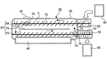
現像装置34は、非磁性トナー(以下、単にトナーという。)及び磁性キャリア(以下、単にキャリアという。)を含む2成分現像剤と、種々の部材を収容する現像槽66と、を備えている。現像槽66は感光体12に向けて開放された開口部を備えており、この開口部の近傍に形成された空間に現像ローラ48が設けられている。現像剤担持体としての現像ローラ48は、円筒状の部材であり、感光体12と平行に且つ感光体12の外周面と所定の現像ギャップを介して、回転可能に枢支されている。
[Development equipment]
The developing
現像ローラ48は、回転不能に固定された磁石体48aと、磁石体48aの周囲を回転可能に支持された円筒状のスリーブ48b(第一の回転円筒体)と、を有するいわゆるマグネットローラである。現像ローラ48のスリーブ48bの上方には、現像槽66に固定され、現像ローラ48のスリーブ48bの中心軸と平行に延在する規制板62が、所定の規制ギャップを介して対向配置されている。現像ローラ48の内側にある磁石体48aは、スリーブ48bの回転方向に沿って、N1、S2、N3、N2、S1という5個の磁極を有する。これらの磁極のうち、主磁極N1は、感光体12と対向するように配置されている。スリーブ48bの上の現像剤を剥離させるための反発磁界を発生させる同極のN2及びN3は、現像槽66の内部に対向配置されている。現像ローラ48のスリーブ48bは、感光体1の回転方向と逆向きに(カウンター方向に)回転する。
The developing
図2は、現像装置34を上から見た模式的断面図である。図2に示すように、現像ローラ48の背後には、現像剤攪拌搬送室67が形成されている。現像剤攪拌搬送室67は、現像ローラ48の近傍に形成された第二搬送路70と現像ローラ48から離れた第一搬送路68と、第一搬送路68及び第二搬送路70を間仕切る隔壁76と、を有する。第一搬送路68の搬送方向の上流側の上方には、現像剤補給タンク80が配設されていて、現像剤補給タンク80が補給口82を介して第一搬送路68と連通している。現像剤補給タンク80には、トナーを主成分としてキャリアを含有する補給用現像剤2が充填されている。補給用現像剤2のキャリア比は、好ましくは5乃至40重量%であり、より好ましくは10乃至30重量%である。また、第二搬送路70の搬送方向の下流側の下方には、現像剤回収タンク90が配設されていて、現像剤回収タンク90が回収口92を介して第二搬送路70と連通している。
FIG. 2 is a schematic cross-sectional view of the developing
現像剤補給タンク80の底部には、制御部100によって駆動制御される現像剤補給ローラが配置されている。補給用モータの回転駆動により現像剤補給ローラが回転することによって、その駆動時間に応じた量の新規の補給用現像剤2が、流下して現像槽66の第一搬送路68に供給される。
A developer supply roller that is driven and controlled by the
第一搬送路68には、現像槽内現像剤3を攪拌しながら搬送する攪拌部材である第一スクリュー72が回転可能に枢支されている。第二搬送路70には、第一搬送路68からの現像槽内現像剤3を攪拌しながら現像ローラ48に搬送する第二スクリュー74が回転可能に枢支されている。第一スクリュー72及び第二スクリュー74は、それぞれ、シャフトに所定のピッチで螺旋状の羽根が固定された通常のスパイラルスクリューである。この場合、第一搬送路68と第二搬送路70との両端部に位置する隔壁76の上部が切り欠かれることによって連絡通路が形成されている。第一搬送路68の搬送方向の下流側端部に到達した現像槽内現像剤3が連絡通路を介して第二搬送路70へ送り込まれ、第二搬送路70の搬送方向の下流側端部に到達した現像槽内現像剤3が連絡通路を介して第一搬送路68に送り込まれる。その結果、図2の矢印方向にしたがって、現像槽内現像剤3が現像剤攪拌搬送室内を循環する。
A
第一スクリュー72及び第二スクリュー74は、シャフトに所定のピッチで螺旋状の羽根が固定されたスパイラルスクリューである。図2の右端部に示すように、第二スクリュー74は、図中の右側に延在して、回収口92の上まで延在している。第二スクリュー74は、第二搬送路70から第一搬送路68に向かう連絡通路及び第二搬送路70の下流側側端部に対応する位置において、スパイラルスクリューの螺旋の向きが他の部分とは逆向きに構成されている逆羽根部を有する。第二スクリュー74の羽根のピッチは、搬送方向の下流側端部(図2の右端部)において他の部分に比べて小さくなっている。その結果、第二スクリュー74が回転すると、第二スクリュー74の搬送方向の下流側端部(右端部)での現像槽内現像剤3の高さが他の部分に比べて高くなる。すなわち、第二搬送路70の搬送方向の下流側端部(右端部)において、現像槽内現像剤3の盛り上がりが形成される。
The
ここで、現像装置34は、いわゆるトリクル方式を採用したものであるから、余剰の現像槽内現像剤3を流出させるための流出口75を有している。すなわち、第二搬送路70の搬送方向の下流側端部(右端部)に位置する側壁の上部が部分的に切り欠かれた切欠75を設けることによって、流出口75が形成されている。第二スクリュー74によって搬送される現像剤は、通常の状態では逆羽根部によってせき止められることにより、図2の実線矢印のように、第二搬送路70から第一搬送路68へと搬送される。現像槽内における現像槽内現像剤3が増えて現像槽内の液面が上昇すると、逆羽根部のせき止め作用に抗して側壁の上部に設けられた流出口75を現像槽内現像剤3が乗り越えて、隣接する回収室に溢出する。回収室に溢出した余剰の現像槽内現像剤3は、回収口92まで搬送され、回収口92を介して現像剤回収タンク90に回収(廃棄)される。
Here, since the developing
図2に示すように、現像剤攪拌搬送室67の底面には、現像剤攪拌搬送室67内でのトナー濃度を検出する磁気式のトナー濃度検出センサ78が設けられている。磁気式のトナー濃度検出センサ78は、例えば、コイルのインダクタンスの変化から、現像槽内現像剤3に含まれる磁性キャリアの透磁率変化を検出して透磁率変化に対応した値を出力する。トナー濃度検出センサ78から出力された出力値に基づいて、現像槽内現像剤3に対するトナーの比率が求められる。例えば、現像槽内現像剤3に含まれるキャリア量が少ない場合は、トナー比率が高いと検出される。一方、現像槽内現像剤3に含まれるキャリア量が多い場合は、トナー比率が低いと検出される。
As shown in FIG. 2, a magnetic toner
現像槽内現像剤3が滞留しやすい場所は、現像槽内現像剤3の充填度合いが高い密状態になっているので、現像槽66内のトナー濃度をより正確に反映している。したがって、トナー濃度検出センサ78は、現像槽内現像剤3が滞留しやすい場所に設置されるが、例えば、図2に示すように、第一搬送路68の最下流位置であって第二搬送路70に向けて屈曲する連絡通路よりも手前の領域、いわゆるベンド領域の周辺に設置される。
The place where the
また、図2に示すように、現像剤攪拌搬送室67の底面には、現像剤攪拌搬送室67内に存在する現像槽内現像剤3の量を推定するための磁気式の現像剤量推定センサ65が設けられている。現像剤量推定センサ65は、現像槽内現像剤3が滞留しにくい場所すなわち、現像槽内現像剤3の充填度合いが低い疎な場所に設置されるが、例えば、図2に示すように、第一搬送路68の大略中間に位置する中間領域に設置される。磁気式の現像剤量推定センサ65は、上記磁気式のトナー濃度検出センサ78と同様に、例えば、コイルのインダクタンスの変化から、現像槽内現像剤3に含まれる磁性キャリアの透磁率変化を検出して透磁率変化に対応した値を出力する。後述するように、トナー濃度検出センサ78により正確に検出されたトナー濃度と、磁気式の現像剤量推定センサ65からの出力値とに基づいて、現像槽内現像剤3の量が推定される。
Further, as shown in FIG. 2, a magnetic developer amount estimation for estimating the amount of
そして、トナー濃度検出センサ78及び現像剤量推定センサ65から出力された各電圧信号は、制御部100に入力され、これらの電圧信号に基づいて、必要な補給量が算出されるとともに、現像剤補給タンク80の現像剤補給ローラが駆動され、所定量の補給用現像剤2が現像槽66内に補給される。
The voltage signals output from the toner
現像装置34において、印字動作により、循環している現像槽内現像剤3のトナー濃度が低下すると、トナーと少量のキャリアとを含有する補給用現像剤2が現像剤補給タンク80から補給される。補給用現像剤2は、トナーとキャリアとが一体的な形態で、あるいはトナーとキャリアとが別々の形態で供給される。補給された新規の補給用現像剤2は、すでに存在する現像槽内現像剤3と混合・攪拌されながら、上記現像剤攪拌搬送室67の第一搬送路68及び第二搬送路70に沿って搬送される。基本的には、トナーは感光体12で消費されるのに対して、キャリアは現像装置34内に蓄積されるが、印刷枚数の増加に伴ってキャリアの帯電性能は次第に低下する。補給用現像剤2にはトナーよりも嵩高いキャリアが少量含まれているので、補給用現像剤2の補給動作に伴って、現像装置34内での現像槽内現像剤3の量が徐々に増加する。そして、嵩の増えた現像槽内現像剤3が現像剤攪拌搬送室67を循環する。現像剤攪拌搬送室67を循環しきれない余剰の現像槽内現像剤3は、逆羽根部を乗り越えて、第二搬送路70の搬送方向の下流側端部(右端部)に設けられた流出口75から流出して、回収口92を介して現像剤回収タンク90に回収される。
In the developing
なお、現像剤攪拌搬送室67を構成する第一搬送路68及び第二搬送路70は、図1のように同じ高さに配置されたり、異なった高さに配置(不図示)されたりして、様々な構成をとることができる。
The
補給用現像剤2の補給量は、トナー濃度検出センサ78によって検出された現像槽内現像剤3のトナー濃度と、画像形成時の画像情報(ドットカウンタ)と、現像剤補給タンク80内での補給用現像剤2に対するキャリア比と、に基づいて決定される。現像剤補給タンク80内での補給用現像剤2に対するキャリア比は、現像装置34内でのキャリアの劣化を抑制するとともに、コストアップを招かない程度に調整される。トナーの補給動作に伴って、キャリアが少しずつ供給される。
The replenishment amount of the
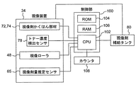
図3は、画像形成装置1の現像装置34に係る制御ブロック図を示している。
FIG. 3 is a control block diagram relating to the developing
制御手段としての制御部100は、CPU(Central Processing Unit)102、ROM(Read Only Memory)104、RAM(Random Access Memory)106等から構成される。ROM104内に格納されている各種処理プログラムやテーブルに従って、CPU102は画像形成装置1での各種動作を集中的に制御する。ROM104には、例えば、トナー濃度検出センサ78から出力された出力電圧値に基づいて現像槽内現像剤3のトナー濃度に変換・算出するためのトナー濃度算出テーブルや、トナー濃度検出センサ78によって得られたトナー濃度と現像剤量推定センサ65からの出力値とに基づいて現像槽内現像剤3の量を推定する現像剤量推定用テーブル又は算出式や、算出されたトナー濃度と推定された現像槽内現像剤3の量とに基づいて補給用現像剤2の量を算出するための現像剤補給用テーブル又は算出式が格納されている。RAM106は、制御部100により実行される各種プログラム及びこれらプログラムに係るデータを一時的に記憶するワークエリアを形成している。
The
CPU102には、現像装置34や現像剤補給タンク80やカウンタ108が接続されている。現像装置34を構成する攪拌部材72,74やトナー濃度検出センサ78や現像剤量推定センサ65や現像ローラ48の動作が、制御部100のCPU102によって制御される。制御部100のCPU102は、攪拌部材72,74の回転数を制御する攪拌部材回転制御手段として用いられている。さらにまた、CPU102は、現像剤量推定センサ65の出力に応じて、現像剤補給タンクから補給される前記予め定められた量を調整する調整手段として用いられている。そして、トナー濃度検出センサ78から出力された出力電圧値や、算出されたトナー濃度や、現像剤量推定センサ65から出力された出力電圧値や、推定された現像槽内現像剤3の量や、画像形成時の画像情報や、現像剤補給タンク80内での補給用現像剤2に対するキャリア比等は、RAM106に一時的に記憶されている。
A developing
〔現像剤〕
2成分現像剤は、トナーと、トナーを帯電させるためのキャリアと、を含んでいる。本発明においては、画像形成装置1において従来から一般的に使用されている公知のトナーが使用可能である。トナーの粒径は、例えば約3乃至15μmである。バインダー樹脂中に着色剤を含有させたトナーや、荷電制御剤や離型剤を含有するトナーや、表面に添加剤を保持するトナーも使用可能である。
(Developer)
The two-component developer contains toner and a carrier for charging the toner. In the present invention, known toners that have been generally used in the
トナーは、例えば、粉砕法、乳化重合法、懸濁重合法等の公知の方法で製造される。 The toner is produced by a known method such as a pulverization method, an emulsion polymerization method, or a suspension polymerization method.
トナーに使用されるバインダー樹脂は、限定的ではないが、例えば、スチレン系樹脂(スチレンまたはスチレン置換体を含む単重合体または共重合体)、ポリエステル樹脂、エポキシ系樹脂、塩化ビニル樹脂、フェノール樹脂、ポリエチレン樹脂、ポリプロピレン樹脂、ポリウレタン樹脂、シリコーン樹脂、またはそれらの樹脂を任意に混ぜ合わせたものである。バインダー樹脂は、軟化温度が約80乃至160℃の範囲であり、ガラス転移点が約50乃至75℃の範囲であることが好ましい。 The binder resin used for the toner is not limited. For example, styrene resin (monopolymer or copolymer containing styrene or styrene-substituted product), polyester resin, epoxy resin, vinyl chloride resin, phenol resin. , Polyethylene resin, polypropylene resin, polyurethane resin, silicone resin, or any mixture of these resins. The binder resin preferably has a softening temperature in the range of about 80 to 160 ° C. and a glass transition point in the range of about 50 to 75 ° C.
着色剤は、公知の材料、例えば、カーボンブラック、アニリンブラック、活性炭、マグネタイト、ベンジンイエロー、パーマネントイエロー、ナフトールイエロー、フタロシアニンブルー、ファーストスカイブルー、ウルトラマリンブルー、ローズベンガル、レーキーレッド等を用いることができる。着色剤の添加量は、一般に、バインダー樹脂100重量部に対して、2乃至20重量部であることが好ましい。 For the colorant, use a known material such as carbon black, aniline black, activated carbon, magnetite, benzine yellow, permanent yellow, naphthol yellow, phthalocyanine blue, first sky blue, ultramarine blue, rose bengal, lake red, etc. Can do. In general, the addition amount of the colorant is preferably 2 to 20 parts by weight with respect to 100 parts by weight of the binder resin.
荷電制御剤は、従来から荷電制御剤として知られている材料が使用できる。具体的に、正極性に帯電するトナーには、例えばニグロシン系染料、4級アンモニウム塩系化合物、トリフェニルメタン系化合物、イミダゾール系化合物、ポリアミン樹脂が荷電制御剤として使用できる。負極性に帯電するトナーには、Cr、Co、Al、Fe等の金属含有アゾ系染料、サリチル酸金属化合物、アルキルサリチル酸金属化合物、カーリックスアレーン化合物が荷電制御剤として使用できる。荷電制御剤は、バインダー樹脂100重量部に対して、0.1乃至10重量部の割合で用いることが好ましい。 As the charge control agent, materials conventionally known as charge control agents can be used. Specifically, for the positively charged toner, for example, nigrosine dyes, quaternary ammonium salt compounds, triphenylmethane compounds, imidazole compounds, and polyamine resins can be used as charge control agents. For the negatively charged toner, metal-containing azo dyes such as Cr, Co, Al, and Fe, salicylic acid metal compounds, alkyl salicylic acid metal compounds, and curixarene compounds can be used as charge control agents. The charge control agent is preferably used at a ratio of 0.1 to 10 parts by weight with respect to 100 parts by weight of the binder resin.
離型剤は、従来から離型剤として使用されている公知のものを使用できる。離型剤の材料には、例えば、ポリエチレン、ポリプロピレン、カルナバワックス、サゾールワックス、又はそれらを適宜組み合わせた混合物が用いられる。離型剤は、バインダー樹脂100重量部に対して、0.1乃至10重量部の割合で用いることが好ましい。 As the release agent, a known release agent conventionally used as a release agent can be used. As the material for the release agent, for example, polyethylene, polypropylene, carnauba wax, sazol wax, or a mixture of them as appropriate is used. The release agent is preferably used at a ratio of 0.1 to 10 parts by weight with respect to 100 parts by weight of the binder resin.
さらに、現像剤の流動化を促進する流動化剤を添加してもよい。流動化剤には、例えば、シリカ、酸化チタン、酸化アルミニウム等の無機微粒子や、アクリル樹脂、スチレン樹脂、シリコーン樹脂、フッ素樹脂等の樹脂微粒子が使用できる。特にシランカップリング剤、チタンカップリング剤、およびシリコンオイル等で疎水化した材料を用いるのが好ましい。流動化剤は、トナー100重量部に対して、0.1乃至5重量部の割合で添加することが好ましい。これら添加剤の個数平均一次粒径は、9乃至100nmであることが好ましい。 Furthermore, a fluidizing agent that promotes fluidization of the developer may be added. As the fluidizing agent, for example, inorganic fine particles such as silica, titanium oxide, and aluminum oxide, and resin fine particles such as acrylic resin, styrene resin, silicone resin, and fluorine resin can be used. In particular, it is preferable to use a material hydrophobized with a silane coupling agent, a titanium coupling agent, silicon oil or the like. The fluidizing agent is preferably added at a ratio of 0.1 to 5 parts by weight with respect to 100 parts by weight of the toner. The number average primary particle size of these additives is preferably 9 to 100 nm.
キャリアは、従来から一般に使用されている公知のキャリアを使用できる。バインダー型キャリアやコート型キャリアのいずれを用いてもよい。キャリア粒径は、限定的ではないが、約15乃至100μmであることが好ましい。 As the carrier, a known carrier that has been generally used can be used. Either a binder type carrier or a coat type carrier may be used. The carrier particle size is not limited, but is preferably about 15 to 100 μm.
バインダー型キャリアは、磁性体微粒子をバインダー樹脂中に分散させたものであり、表面に正極性または負極性に帯電する微粒子又はコーティング層を有するものが使用できる。バインダー型キャリアの極性等の帯電特性は、バインダー樹脂の材質、帯電性微粒子、表面コーティング層の種類によって制御できる。 The binder type carrier is obtained by dispersing magnetic fine particles in a binder resin, and those having fine particles or a coating layer charged positively or negatively on the surface can be used. The charging characteristics such as the polarity of the binder type carrier can be controlled by the material of the binder resin, the chargeable fine particles, and the type of the surface coating layer.
バインダー型キャリアに用いられるバインダー樹脂としては、ポリスチレン系樹脂に代表されるビニル系樹脂、ポリエステル系樹脂、ナイロン系樹脂、ポリオレフィン系樹脂などの熱可塑性樹脂、フェノール樹脂等の硬化性樹脂が例示される。 Examples of the binder resin used for the binder-type carrier include thermoplastic resins such as vinyl resins, polyester resins, nylon resins, polyolefin resins, and the like typified by polystyrene resins, and curable resins such as phenol resins. .
バインダー型キャリアの磁性体微粒子としては、マグネタイト、ガンマ酸化鉄等のスピネルフェライト、鉄以外の金属(Mn、Ni、Mg、Cu等)を一種または二種以上含有するスピネルフェライト、バリウムフェライト等のマグネトプランバイト型フェライト、表面に酸化層を有する鉄や合金の粒子を用いることができる。キャリアの形状は、粒状、球状、針状のいずれであってもよい。特に高磁化を要する場合には、鉄系の強磁性微粒子を用いることが好ましい。化学的な安定性を考慮すると、マグネタイト、ガンマ酸化鉄を含むスピネルフェライトやバリウムフェライト等のマグネトプランバイト型フェライトの強磁性微粒子を用いることが好ましい。強磁性微粒子の種類及び含有量を適宜選択することにより、所望の磁化を有する磁性樹脂キャリアを得ることができる。磁性体微粒子は磁性樹脂キャリア中に50乃至90重量%の量で添加することが適切である。 Magnetic fine particles of the binder type carrier include spinel ferrite such as magnetite and gamma iron oxide, and magnets such as spinel ferrite and barium ferrite containing one or more metals other than iron (Mn, Ni, Mg, Cu, etc.). Plumbite type ferrite, iron or alloy particles having an oxide layer on the surface can be used. The shape of the carrier may be granular, spherical, or needle-shaped. In particular, when high magnetization is required, it is preferable to use iron-based ferromagnetic fine particles. In consideration of chemical stability, it is preferable to use ferromagnetic fine particles of magnetoplumbite type ferrite such as spinel ferrite and barium ferrite containing magnetite and gamma iron oxide. A magnetic resin carrier having a desired magnetization can be obtained by appropriately selecting the type and content of the ferromagnetic fine particles. The magnetic fine particles are suitably added in an amount of 50 to 90% by weight in the magnetic resin carrier.
バインダー型キャリアの表面コート材としては、シリコーン樹脂、アクリル樹脂、エポキシ樹脂、フッ素系樹脂等が用いられる。これらの樹脂をキャリア表面にコートし硬化させてコート層を形成することにより、キャリアの電荷付与能力を向上できる。 Silicone resin, acrylic resin, epoxy resin, fluorine resin, etc. are used as the surface coating material for the binder type carrier. The charge imparting ability of the carrier can be improved by coating and curing these resins on the carrier surface to form a coat layer.
バインダー型キャリアの表面への帯電性微粒子あるいは導電性微粒子の固着は、例えば、磁性樹脂キャリアと微粒子とを均一混合し、磁性樹脂キャリアの表面にこれら微粒子を付着させた後、機械的・熱的な衝撃力を与えることにより微粒子を磁性樹脂キャリア中に打ち込むことで行われる。この場合、微粒子は、磁性樹脂キャリア中に完全に埋設されるのではなく、その一部が磁性樹脂キャリア表面から突出するように固定される。帯電性微粒子には、有機、無機の絶縁性材料が用いられる。具体的に、有機系の絶縁性材料としては、ポリスチレン、スチレン系共重合物、アクリル樹脂、各種アクリル共重合物、ナイロン、ポリエチレン、ポリプロピレン、フッ素樹脂およびこれらの架橋物などの有機絶縁性微粒子がある。電荷付与能力および帯電極性は、帯電性微粒子の素材、重合触媒、表面処理等に調整できる。無機系の絶縁性材料としては、シリカ、二酸化チタン等の負極性に帯電する無機微粒子や、チタン酸ストロンチウム、アルミナ等の正極性に帯電する無機微粒子が用いられる。 For example, the charging fine particles or the conductive fine particles are fixed to the surface of the binder-type carrier by, for example, mixing the magnetic resin carrier and the fine particles uniformly, adhering these fine particles to the surface of the magnetic resin carrier, and then mechanically / thermally. This is done by driving fine particles into the magnetic resin carrier by applying a strong impact force. In this case, the fine particles are not completely embedded in the magnetic resin carrier, but are fixed so that a part thereof protrudes from the surface of the magnetic resin carrier. Organic and inorganic insulating materials are used for the chargeable fine particles. Specifically, organic insulating materials include polystyrene, styrene-based copolymers, acrylic resins, various acrylic copolymers, nylon, polyethylene, polypropylene, fluororesin, and cross-linked products thereof such as organic insulating fine particles. is there. The charge imparting ability and the charge polarity can be adjusted to the material of the chargeable fine particles, the polymerization catalyst, the surface treatment and the like. As the inorganic insulating material, negatively charged inorganic fine particles such as silica and titanium dioxide, and positively charged inorganic fine particles such as strontium titanate and alumina are used.
コート型キャリアは、磁性体からなるキャリアコア粒子を樹脂で被覆したキャリアであり、バインダー型キャリア同様に、キャリア表面に正極性または負極性に帯電する帯電性微粒子を固着することができる。コート型キャリアの極性等の帯電特性は、表面コーティング層の種類や帯電性微粒子の選択により調整できる。コーティング樹脂は、バインダー型キャリアのバインダー樹脂と同様の樹脂が使用可能である。 The coat type carrier is a carrier in which carrier core particles made of a magnetic material are coated with a resin, and like the binder type carrier, chargeable fine particles that are charged positively or negatively can be fixed to the surface of the carrier. The charging characteristics such as the polarity of the coated carrier can be adjusted by selecting the type of the surface coating layer and the electrifying fine particles. As the coating resin, the same resin as the binder resin of the binder type carrier can be used.
現像槽内現像剤3のトナー及びキャリアの混合比は、所望のトナー帯電量が得られるように調整される。現像槽内現像剤3のトナー比は、トナー及びキャリアの合計量に対して、好ましくは3乃至20重量%であり、より好ましくは4乃至15重量%である。また、現像剤補給タンク80に充填されている補給用現像剤2は、トナー及び少量のキャリアを含有したものであり、補給用現像剤2のキャリア比は、好ましくは1乃至50重量%であり、より好ましくは5乃至30重量%である。
The mixing ratio of the toner and the carrier in the
このように構成された現像装置34の動作を説明する。
The operation of the developing
画像形成時、図示しないモータの駆動に基づいて、現像ローラ48のスリーブ48bは矢印方向(反時計回り)に回転する。第一スクリュー72の回転及び第二スクリュー74の回転により、現像剤攪拌搬送室67に存する現像槽内現像剤3は、第一搬送路68と第二搬送路70とを循環搬送されながら、攪拌される。その結果、現像剤に含まれるトナーとキャリアとが摩擦接触し、互いに逆の極性に帯電される。実施形態では、キャリアは正極性、トナーは負極性に帯電されるものとする。本発明に用いるトナー及びキャリアの帯電性は、このような組み合わせに限定されるものでない。キャリアの外形寸法は、トナーに比べて相当大きい。そのため、正極性に帯電したキャリアの周囲に、負極性に帯電したトナーが、主として両者の電気的な吸引力に基づいて付着している。
During image formation, the
帯電された現像槽内現像剤3は、第二スクリュー74によって第二搬送路70に搬送される過程で現像ローラ48に供給される。この現像剤は、現像ローラ48内部の磁石体48aの磁力によってスリーブ48bの表面側に保持され、スリーブ48bと共に反時計周り方向に回転移動して、現像ローラ48に対向して設けられた規制板62で通過量を規制された後、感光体12と対向する現像領域へと搬送される。そして、現像領域において、磁石体48aの主磁極N1の磁力によって穂立ち(磁気ブラシ)が形成される。現像領域では、感光体12上の静電潜像と現像バイアスの印加された現像ローラ48との間に形成された電界(直流に交流が重畳された電界)がトナーに与える力により、トナーが感光体12上の静電潜像側へと移動して、この静電潜像が顕像へと現像される。現像領域でトナーを消費した現像剤は、現像槽66に向けて搬送され、現像槽66の第二搬送路70に対向して設けられた磁石体48aのN3,N2の反発磁界によって現像ローラ48上から剥離され、現像槽66内へと回収される。回収された現像剤は、第二搬送路70を搬送されている現像槽内現像剤3と混合される。
The charged
このような画像形成によって現像槽内現像剤3の中からトナーが消費されると、消費された量に見合う量のトナーが現像槽66へ補給されることが好ましい。そのために、現像装置34は、現像剤攪拌搬送室67に存する現像槽内現像剤3に対するトナーの比を測定するトナー濃度検出センサ78を備えている。また、第一搬送路68の上方には現像剤補給タンク80が設けてある。
When the toner is consumed from the
次に、本発明の一実施形態に係る現像装置34の動作を、図4乃至6を参照しながら説明する。
Next, the operation of the developing
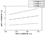
図4は、現像剤量推定センサ65の出力電圧値Pと推定された現像槽内現像剤3の量Gとの関係を示すグラフである。図5は、推定された現像槽内現像剤3の量Gと補給すべき現像剤の量Sとの関係を示すグラフである。図6は、図示しない全体制御(メインルーチン)のうちの現像剤補給制御のサブルーチンに関するフローチャートである。
FIG. 4 is a graph showing the relationship between the output voltage value P of the developer
トナー濃度検出センサ78によって得られたあるトナー濃度Tcに対して、現像剤量推定センサ65の出力電圧値をPとし、推定された現像剤の量をGとすると、両者の関係を実験的に求めると、例えば、以下のような二次の現像剤量推定用算出式(1)に近似される。
G=−33.333×P2+(−33.335×Tc+490)×P+(128.34×Tc−1116) (1)
With respect to a certain toner concentration Tc obtained by the toner
G = −33.333 × P 2 + (− 33.335 × Tc + 490) × P + (128.34 × Tc−1116) (1)
図4は、一例として、トナー濃度Tcがそれぞれ6、7、8重量%である場合を示している。上記の二次の現像剤量推定用算出式(1)がROM104に格納されていて、トナー濃度Tcと現像剤量推定センサ65の出力電圧値Pとが得られると、現像槽内現像剤3の量Gを推定することができる。例えば、検出されたトナー濃度Tcが7重量%であり、現像剤量推定センサ65の出力電圧値Pが2.6Vであるとき、現像槽内現像剤3の量Gは約224gと推定される。
FIG. 4 shows, as an example, cases where the toner concentrations Tc are 6, 7 and 8% by weight, respectively. When the calculation formula (1) for estimating the secondary developer amount is stored in the
上記算出式(1)により現像槽内現像剤3の量Gが推定されると、トナー濃度検出センサ78によって得られたあるトナー濃度Tcに対して、補給すべき補給用現像剤2の量Sが以下のような線形の算出式(2)によって算出される。なお、補給用現像剤2のキャリア比が20重量%であり、基準トナー濃度が7重量%であるという条件で補給量Sの算出式(2)を得られている。
S=(−1.37×(Tc/100)+0.0959)×G (2)
When the amount G of the
S = (− 1.37 × (Tc / 100) +0.0959) × G (2)
図5は、一例として、7重量%という目標に対してトナー濃度Tcが4、5、6重量%の場合を示している。上記の線形の補給量算出式(2)がROM104に格納されていて、検出されたトナー濃度Tcと推定された現像槽内現像剤3の量Gとにより、補給すべき補給用現像剤2の量Sを求めることができる。例えば、検出されたトナー濃度Tcが6重量%であり、推定された現像槽内現像剤3の量Gが230gであるとき、補給すべき補給用現像剤2の量Sは3.15gとなる。
FIG. 5 shows, as an example, cases where the toner concentration Tc is 4, 5, or 6% by weight with respect to the target of 7% by weight. The linear replenishment amount calculation formula (2) is stored in the
現像装置34内の現像剤量Gが少ないと推定された場合、多量の補給用現像剤2の補給を継続的に行うと相対的に補給過多になってしまい、現像装置34内でのトナー濃度Tcが高めに推移してしまう。そこで、現像装置34内の現像剤量Gが少ないと推定された場合、少量の補給用現像剤2の補給が行われる。また、現像装置34内の現像剤量Gが多いと推定された場合、少量の補給用現像剤2の補給を継続的に行うと相対的に補給過少になってしまい、現像装置34内でのトナー濃度Tcが低めに推移してしまう。そこで、現像装置34内の現像剤量が多いと推定された場合、多量の補給用現像剤2の補給が行われる。
When it is estimated that the developer amount G in the developing
補給用現像剤2の補給量の調整は、現像剤補給ローラの駆動時間を調整することによって行われる。補給量に対応した現像剤補給ローラの駆動時間が実験的に予め求められていて、例えば、上記補給量算出式(2)によって具体的な補給量が決定されると、補給量に対応した現像剤補給ローラの駆動時間が決定される。現像剤補給ローラの駆動時間に応じた補給用現像剤2が、流下して現像槽66の第一搬送路68に供給される。
The replenishment amount of the
図6を参照しながら、本願発明の特徴部分である現像剤補給制御方法について説明する。 With reference to FIG. 6, the developer replenishment control method, which is a characteristic part of the present invention, will be described.
ステップS102において、トナー濃度検出センサ78から出力された出力電圧値が測定される。そして、ステップS104において、ステップS102で得られた出力電圧値に基づいて、現像槽66内での現像槽内現像剤3のトナー濃度Tcが算出される。
In step S102, the output voltage value output from the toner
ステップS106において、現像剤量推定センサ65から出力された出力電圧値Pが測定される。ステップS108において、ステップS104で算出されたトナー濃度Tcと、ステップS104で得られた出力電圧値Pとに基づいて、現像槽66内での現像槽内現像剤3の量Gが推定される。
In step S106, the output voltage value P output from the developer
ステップS110において、算出されたトナー濃度Tcと、推定された現像槽内現像剤3の量Gとに基づいて、トナーの補給量すなわち補給用現像剤2の補給量Sが算出される。
In step S110, based on the calculated toner concentration Tc and the estimated amount G of the
ステップS112において、現像剤補給用のテーブル又は算出式を参照することにより、補給用現像剤2の補給量Sに対応した現像剤補給ローラの駆動時間が算出される。ステップS114において、算出された駆動時間にわたって現像剤補給ローラが駆動される。その結果、ステップS116において、現像剤補給ローラの駆動時間に応じた補給用現像剤2が、流下して現像槽66の第一搬送路68に供給される。
In step S112, the developer replenishment roller driving time corresponding to the replenishment amount S of the
上記実施形態によれば、算出されたトナー濃度Tcと推定された現像剤量Gとから、所望とするトナー濃度Tcとするために必要な補給量Sが算出され、当該補給量Sが現像槽66へ補給される。したがって、二成分現像剤を用いたトリクル方式の現像装置34に対して、現像装置34内のトナー濃度Tc及び現像剤量Gに応じて適切な量の補給用現像剤2が補給されることにより、長期にわたって良好な画像形成を行うことができる。
According to the above embodiment, the replenishment amount S required to obtain the desired toner concentration Tc is calculated from the calculated toner concentration Tc and the estimated developer amount G, and the replenishment amount S is calculated as the developing tank. 66 is replenished. Therefore, by supplying a proper amount of the
次に、第二実施形態に係る現像装置34を、図7及び8を参照しながら説明する。なお、第二実施形態の特徴部分を除く他の構成は上述した第一実施形態と同じであるので、特徴部分以外の他の構成に関する説明を省略する。
Next, the developing
図7は、本発明の第二実施形態に係る現像装置34の概略構成を示す図である。図8は、図7に示した現像装置34を上から見た模式的断面図である。
FIG. 7 is a diagram showing a schematic configuration of the developing
図7及び8に示す第二実施形態に係る現像装置34は、上記第一実施形態の変形例であって、トナー濃度検出センサ78が、第一搬送路68の側面視、現像剤量推定センサ65よりも下方に設置されていることを特徴としている。
The developing
上述したように、トナー濃度検出センサ78は現像槽66内における現像槽内現像剤3の充填度合いの高い場所に設置され、現像剤量推定センサ65は、現像槽66内における現像槽内現像剤3の充填度合いの低い場所に設置される。トナー濃度検出センサ78と現像剤量推定センサ65とが第一搬送路68の下流側の大略同じ断面上に存在する場合、トナー濃度検出センサ78及び現像剤量推定センサ65は、それぞれ、以下のような場所に設置される。
As described above, the toner
図7及び8に示すように、トナー濃度検出センサ78が現像槽66の第一搬送路68の底面部分に設置され、現像剤量推定センサ65が現像槽66の側面部分に設置される。あるいは、不図示ではあるが、トナー濃度検出センサ78及び現像剤量推定センサ65の両方が現像槽66の第一搬送路68の側面部分に設置され、且つ、トナー濃度検出センサ78が、現像剤量推定センサ65よりも下方に設置された形態であってもよい。
As shown in FIGS. 7 and 8, the toner
いずれの実施形態においても、算出されたトナー濃度Tcと推定された現像剤量Gとから、所望とするトナー濃度とするために必要な補給量Sが算出され、当該補給量Sが現像槽66へ補給される。したがって、二成分現像剤を用いたトリクル方式の現像装置34に対して、現像装置34内のトナー濃度Tc及び現像剤量Gに応じて適切な量の補給用現像剤2が補給されることにより、長期にわたって良好な画像形成を行うことができる。
In any of the embodiments, the replenishment amount S required to obtain a desired toner concentration is calculated from the calculated toner concentration Tc and the estimated developer amount G, and the replenishment amount S is calculated as the developing
なお、上記実施形態においては、具体的な数値を用いながら説明したが、当該数値によって本願発明が限定されるものではなく、特許請求の範囲及び均等物によって画定される範囲を逸脱しない範囲で本願発明を様々に変形させることができる。 In the above embodiment, the description has been made using specific numerical values, but the present invention is not limited by the numerical values, and the present application is not deviated from the scope defined by the claims and equivalents. The invention can be modified in various ways.
上記実施形態においては、トナー濃度検出センサ78及び現像剤量推定センサ65の両方ともが、像槽内現像剤3に含まれる磁性キャリアの透磁率変化を検出する磁気式のセンサを用いているが、検出原理の異なった他のセンサを用いることができる。例えば、現像剤から反射光の光量を検知する光学式のセンサが使用可能である。トナー濃度検出センサ78及び現像剤量推定センサ65の両方ともが、光学式のセンサを用いることができる。あるいは、いずれか一方に磁気式のセンサを用い、他方に光学式のセンサを用いることができる。なお、カーボンブラックを色材としてブラックトナーとキャリアとからなる黒色の現像剤に対しては、光学式のセンサを用いることはできない。
In the above-described embodiment, both the toner
さらに、現像槽66内における現像槽内現像剤3の量に応じて単位面積当たりの圧力も変化することから、現像剤量推定センサ65として、薄ゲージ式、半導体ストレインゲージ式、圧電式あるいは光ファイバー式等の圧力センサを用いることもできる。したがって、圧力センサをトナー濃度検出センサ78として現像槽66の第一搬送路68の底面部分に設置する形態であってもよい。
Further, since the pressure per unit area also changes in accordance with the amount of the
前述の実施形態では、現像槽内現像剤3の量Gと、トナー濃度検出センサ78によって得られたトナー濃度Tcと、に基づいて補給量Sを算出しているが、このような方法に限定されるものではなく、ROM104内に現像剤量推定用テーブルを予め用意しておくことにより、現像剤量推定センサ65とトナー濃度検出センサ78との出力値から補給量Sを求めるようにしてもよい。
In the above-described embodiment, the replenishment amount S is calculated based on the amount G of the
また、トナー濃度検出センサ78の出力に応じて補給量S1を仮決定するとともに、現像剤量推定センサ65の出力に基づいて算出された現像剤量Gに応じて、補給量S1を所定の比率で増減するようにしてもよい。具体的には、例えば現像剤量Gが230gよりも多い場合には補給量がより多くなるように、あるいは現像剤量Gが230gよりも少ない場合には補給量がより少なくなるように、比率をそれぞれ設定すればよい。
Further, the replenishment amount S1 is provisionally determined according to the output of the toner
1:画像形成装置
2:補給用現像剤
3:現像槽内現像剤
12:感光体
20:定着装置
22:定着ローラ
26:帯電装置
28:露光装置
30:画像光
34:現像装置
36:転写装置
38:用紙
40:クリーニング装置
48:現像ローラ(現像剤担持体)
48a:磁石体
48b:スリーブ
56:搬送状態切替手段
62:規制板
65:現像剤量推定センサ
66:現像槽
67:現像剤攪拌搬送室
68:第一搬送路
70:第二搬送路
72:第一スクリュー(攪拌部材)
74:第二スクリュー(攪拌部材)
75:切欠(流出口)
76:隔壁
78:トナー濃度検出センサ
80:現像剤補給タンク
82:補給口
90:現像剤回収タンク
92:回収口
100:制御部
102:中央演算処理装置(CPU)
104:読み出し専用メモリ(ROM)
106:読み書き可能メモリ(RAM)
108:カウンタ
1: Image forming apparatus 2: Developer for replenishment 3: Developer in developer tank 12: Photoconductor 20: Fixing device 22: Fixing roller 26: Charging device 28: Exposure device 30: Image light 34: Developing device 36: Transfer device 38: Paper 40: Cleaning device 48: Developing roller (developer carrier)
48a:
74: Second screw (stirring member)
75: Notch (outlet)
76: Partition 78: Toner concentration detection sensor 80: Developer supply tank 82: Supply port 90: Developer recovery tank 92: Recovery port 100: Control unit 102: Central processing unit (CPU)
104: Read-only memory (ROM)
106: Read / write memory (RAM)
108: Counter
Claims (14)
トナー及びキャリアを現像槽へ補給する現像剤補給タンクと、
前記現像槽内のトナー濃度を検出するトナー濃度検出センサと、
前記現像槽内に存在する現像槽内現像剤の量を推定する現像剤量推定センサと、
前記現像槽に設けられ、現像槽内の現像槽内現像剤の量が所定量を上回ったときに、上回った現像槽内現像剤を現像槽外に排出する排出機構と、
トナー濃度検出センサによって検出されたトナー濃度が予め定められた基準トナー濃度よりも低いとき、現像剤補給タンクから補給用のトナー及びキャリアを現像槽へ補給する補給動作を制御する制御手段と、を備えてなり、
前記制御手段は、検出されたトナー濃度と推定された現像剤量とに基づいて、補給すべきトナー及びキャリアの量を決定することを特徴とする現像装置。 An agitating member for agitating the developer in the developing tank containing the toner and the carrier while being conveyed in the developing tank, and development for supplying the agitated developer in the developing tank adjacent to the agitating member to the electrostatic latent image carrier. A developing device comprising an agent carrier,
A developer supply tank for supplying toner and carrier to the developer tank;
A toner concentration detection sensor for detecting a toner concentration in the developing tank;
A developer amount estimation sensor for estimating the amount of developer in the developer tank present in the developer tank;
A discharge mechanism that is provided in the developing tank and discharges the developer in the developing tank that has exceeded the amount outside the developing tank when the amount of the developer in the developing tank exceeds a predetermined amount;
Control means for controlling a replenishment operation for replenishing the developer tank with replenishment toner and carrier from the developer replenishment tank when the toner concentration detected by the toner concentration detection sensor is lower than a predetermined reference toner density; Prepared
The developing device is characterized in that the control means determines the amount of toner and carrier to be replenished based on the detected toner density and the estimated developer amount.
トナー及びキャリアを現像槽へ補給する現像剤補給タンクと、
前記現像槽内のトナー濃度を検出するトナー濃度検出センサと、
前記現像槽内に存在する現像槽内現像剤の量を推定する現像剤量推定センサと、
前記現像槽に設けられ、現像槽内の現像槽内現像剤の量が所定量を上回ったときに、上回った現像槽内現像剤を現像槽外に排出する排出機構と、
トナー濃度検出センサによって検出されたトナー濃度が予め定められた基準トナー濃度よりも低いとき、現像剤補給タンクから補給用のトナー及びキャリアを現像槽へ補給する補給動作を制御する制御手段と、を備えてなり、
前記制御手段は、検出されたトナー濃度と推定された現像剤量とに基づいて、補給すべきトナー及びキャリアの量を決定することを特徴とする画像形成装置。 A rotatable electrostatic latent image carrier that carries an electrostatic latent image on its peripheral surface, an agitating member that agitates the developer in the developing tank containing toner and carrier in the developing tank, and adjacent to the agitating member A developer carrying member for supplying the developer in the developing tank, which is arranged and stirred, to the electrostatic latent image carrier, and an image forming apparatus comprising:
A developer supply tank for supplying toner and carrier to the developer tank;
A toner concentration detection sensor for detecting a toner concentration in the developing tank;
A developer amount estimation sensor for estimating the amount of developer in the developer tank present in the developer tank;
A discharge mechanism that is provided in the developing tank and discharges the developer in the developing tank that has exceeded the amount outside the developing tank when the amount of the developer in the developing tank exceeds a predetermined amount;
Control means for controlling a replenishment operation for replenishing the developer tank with replenishment toner and carrier from the developer replenishment tank when the toner concentration detected by the toner concentration detection sensor is lower than a predetermined reference toner density; Prepared
The image forming apparatus according to claim 1, wherein the control unit determines the amount of toner and carrier to be replenished based on the detected toner density and the estimated developer amount.
トナー濃度検出センサによりトナー濃度を算出するトナー濃度算出工程と、
現像剤量推定センサにより現像槽内現像剤の量を推定する現像剤量推定工程と、
算出されたトナー濃度と推定された現像剤量とに基づいて、補給すべきトナー及びキャリアの量を決定する補給量決定工程と、
補給量決定工程により決定されたトナー及びキャリアの量を現像剤補給タンクから現像槽へ補給する補給工程と、
を備えることを特徴とする現像方法。 An agitating member for agitating the developer in the developing tank containing the toner and the carrier while being conveyed in the developing tank, and development for supplying the agitated developer in the developing tank adjacent to the agitating member to the electrostatic latent image carrier. A developer carrier, a developer supply tank for supplying toner and carrier to the developer tank, a toner concentration detection sensor for detecting the toner density in the developer tank, and the amount of developer in the developer tank present in the developer tank A developer amount estimation sensor for estimating the developer amount, and when the amount of the developer in the developer tank in the developer tank exceeds a predetermined amount, the developer in the developer tank that has exceeded is discharged to the outside of the developer tank. Control for controlling the replenishment operation of replenishing the developer tank with replenishment toner and carrier from the developer replenishment tank when the toner density detected by the discharge mechanism and the toner density detection sensor is lower than a predetermined reference toner density hand When, a developing method applied to a developing device provided with,
A toner concentration calculation step of calculating a toner concentration by a toner concentration detection sensor;
A developer amount estimation step of estimating the amount of developer in the developing tank by a developer amount estimation sensor;
A replenishment amount determination step for determining the amount of toner and carrier to be replenished based on the calculated toner density and the estimated developer amount;
A replenishment step of replenishing the amount of toner and carrier determined in the replenishment amount determination step from the developer replenishment tank to the developing tank;
A developing method comprising the steps of:
該現像槽内の現像槽内現像剤を静電潜像担持体へ供給する現像剤担持体と、
現像槽内において現像剤担持体に隣接して配置され、現像槽内現像剤を現像槽内で循環・搬送しながら攪拌する攪拌部材と、
トナー及びキャリアを現像槽へ補給する現像剤補給タンクと、
現像槽内における現像槽内現像剤の充填度合いの高い場所に設置された第一トナー濃度検出センサと、
該第一トナー濃度検出センサの出力に応じて予め定められた量のトナー及びキャリアを現像剤補給タンクから現像槽へ補給する補給手段と、
前記現像槽に設けられ、現像槽内の現像槽内現像剤の量が所定量を上回ったときに、上回った現像槽内現像剤を現像槽外に排出する排出機構と、
現像槽内における現像槽内現像剤の充填度合いの低い場所に設置された第二トナー濃度検出センサと、
該第二トナー濃度検出センサの出力に応じて、現像剤補給タンクから補給される前記予め定められた量を調整する調整手段と、
を備えることを特徴とする現像装置。 A developing tank containing a developer in the developing tank containing toner and a carrier;
A developer carrying body for supplying the developer in the developing tank to the electrostatic latent image carrying body;
An agitating member that is disposed adjacent to the developer carrying member in the developing tank, and agitates the developer in the developing tank while circulating and conveying the developer in the developing tank;
A developer supply tank for supplying toner and carrier to the developer tank;
A first toner concentration detection sensor installed in a place where the degree of filling of the developer in the developer tank is high in the developer tank;
Replenishment means for replenishing a predetermined amount of toner and carrier from the developer replenishment tank to the developing tank according to the output of the first toner concentration detection sensor;
A discharge mechanism that is provided in the developing tank and discharges the developer in the developing tank that has exceeded the amount outside the developing tank when the amount of the developer in the developing tank exceeds a predetermined amount;
A second toner concentration detection sensor installed in a place where the degree of developer filling in the developing tank is low in the developing tank;
Adjusting means for adjusting the predetermined amount replenished from the developer replenishing tank according to the output of the second toner concentration detection sensor;
A developing device comprising:
Priority Applications (2)
| Application Number | Priority Date | Filing Date | Title |
|---|---|---|---|
| JP2008153885A JP2009300645A (en) | 2008-06-12 | 2008-06-12 | Developing device and image forming apparatus |
| US12/395,906 US8023839B2 (en) | 2008-06-12 | 2009-03-02 | Developing apparatus and image forming machine |
Applications Claiming Priority (1)
| Application Number | Priority Date | Filing Date | Title |
|---|---|---|---|
| JP2008153885A JP2009300645A (en) | 2008-06-12 | 2008-06-12 | Developing device and image forming apparatus |
Publications (1)
| Publication Number | Publication Date |
|---|---|
| JP2009300645A true JP2009300645A (en) | 2009-12-24 |
Family
ID=41414913
Family Applications (1)
| Application Number | Title | Priority Date | Filing Date |
|---|---|---|---|
| JP2008153885A Pending JP2009300645A (en) | 2008-06-12 | 2008-06-12 | Developing device and image forming apparatus |
Country Status (2)
| Country | Link |
|---|---|
| US (1) | US8023839B2 (en) |
| JP (1) | JP2009300645A (en) |
Cited By (3)
| Publication number | Priority date | Publication date | Assignee | Title |
|---|---|---|---|---|
| US10054872B2 (en) | 2016-03-02 | 2018-08-21 | Canon Kabushiki Kaisha | Image forming apparatus having removable developing units |
| JP2018189820A (en) * | 2017-05-08 | 2018-11-29 | 京セラドキュメントソリューションズ株式会社 | Image forming apparatus |
| JP2019120805A (en) * | 2018-01-05 | 2019-07-22 | コニカミノルタ株式会社 | Image formation device, development device, and developer liquid surface detection program |
Families Citing this family (9)
| Publication number | Priority date | Publication date | Assignee | Title |
|---|---|---|---|---|
| JP4298733B2 (en) * | 2006-09-25 | 2009-07-22 | シャープ株式会社 | Developer recovery apparatus and image forming apparatus including the same |
| JP5971953B2 (en) * | 2012-01-10 | 2016-08-17 | キヤノン株式会社 | Development device |
| JP5358706B2 (en) | 2012-02-20 | 2013-12-04 | 京セラドキュメントソリューションズ株式会社 | Developer transport mechanism, developing device including the same, and image forming apparatus |
| JP5754467B2 (en) * | 2013-06-12 | 2015-07-29 | コニカミノルタ株式会社 | Developing device and image forming apparatus |
| JP5925240B2 (en) * | 2014-04-18 | 2016-05-25 | シャープ株式会社 | Conveying device, developing device, and image forming apparatus |
| JP5847883B2 (en) * | 2014-05-13 | 2016-01-27 | シャープ株式会社 | Conveying device, developing device, and image forming apparatus |
| WO2017098829A1 (en) * | 2015-12-11 | 2017-06-15 | 株式会社村田製作所 | Toner bottle |
| JP2018005073A (en) * | 2016-07-06 | 2018-01-11 | 京セラドキュメントソリューションズ株式会社 | Image formation device |
| JP7434775B2 (en) * | 2019-09-20 | 2024-02-21 | 富士フイルムビジネスイノベーション株式会社 | image forming device |
Citations (3)
| Publication number | Priority date | Publication date | Assignee | Title |
|---|---|---|---|---|
| JPH1165280A (en) * | 1997-08-13 | 1999-03-05 | Fuji Xerox Co Ltd | Developing device |
| JP2001166593A (en) * | 1999-12-08 | 2001-06-22 | Konica Corp | Developing device and image forming device |
| JP2001255743A (en) * | 2000-03-09 | 2001-09-21 | Konica Corp | Developing device and image forming device |
Family Cites Families (4)
| Publication number | Priority date | Publication date | Assignee | Title |
|---|---|---|---|---|
| JPS5910047A (en) | 1982-07-08 | 1984-01-19 | Nissan Motor Co Ltd | Multiplex communication system |
| JPH05341654A (en) | 1992-03-05 | 1993-12-24 | Canon Inc | Image forming device |
| US5365319A (en) | 1992-03-05 | 1994-11-15 | Canon Kabushiki Kaisha | Image forming apparatus replenishing toner by detecting the ratio of toner and carrier and the density of the developer |
| JP2001265125A (en) * | 2000-03-16 | 2001-09-28 | Nec Niigata Ltd | Liquid developing machine and image forming device using the same |
-
2008
- 2008-06-12 JP JP2008153885A patent/JP2009300645A/en active Pending
-
2009
- 2009-03-02 US US12/395,906 patent/US8023839B2/en not_active Expired - Fee Related
Patent Citations (3)
| Publication number | Priority date | Publication date | Assignee | Title |
|---|---|---|---|---|
| JPH1165280A (en) * | 1997-08-13 | 1999-03-05 | Fuji Xerox Co Ltd | Developing device |
| JP2001166593A (en) * | 1999-12-08 | 2001-06-22 | Konica Corp | Developing device and image forming device |
| JP2001255743A (en) * | 2000-03-09 | 2001-09-21 | Konica Corp | Developing device and image forming device |
Cited By (3)
| Publication number | Priority date | Publication date | Assignee | Title |
|---|---|---|---|---|
| US10054872B2 (en) | 2016-03-02 | 2018-08-21 | Canon Kabushiki Kaisha | Image forming apparatus having removable developing units |
| JP2018189820A (en) * | 2017-05-08 | 2018-11-29 | 京セラドキュメントソリューションズ株式会社 | Image forming apparatus |
| JP2019120805A (en) * | 2018-01-05 | 2019-07-22 | コニカミノルタ株式会社 | Image formation device, development device, and developer liquid surface detection program |
Also Published As
| Publication number | Publication date |
|---|---|
| US20090310984A1 (en) | 2009-12-17 |
| US8023839B2 (en) | 2011-09-20 |
Similar Documents
| Publication | Publication Date | Title |
|---|---|---|
| JP2009300645A (en) | Developing device and image forming apparatus | |
| JP4636122B2 (en) | Developing device and image forming apparatus | |
| JP4697241B2 (en) | Developing device and image forming apparatus | |
| JP4605258B2 (en) | Developing device and image forming apparatus | |
| JP4586866B2 (en) | Developing device and image forming apparatus | |
| JP4450033B2 (en) | Developing device and image forming apparatus | |
| JP2009237427A (en) | Developing device, image forming apparatus and method for filling developer | |
| JP4841576B2 (en) | Developing device and image forming apparatus | |
| JP2010025987A (en) | Developing device and image forming apparatus | |
| JP4814267B2 (en) | Developing device and image forming apparatus | |
| JP4591543B2 (en) | Developing device and image forming apparatus | |
| JP2009192701A (en) | Developing device and image forming apparatus | |
| JP2009244552A (en) | Developing device and image forming apparatus | |
| JP2009223118A (en) | Developing method, developing device and image forming apparatus | |
| JP4710928B2 (en) | Developing device and image forming apparatus | |
| JP4645660B2 (en) | Developing device and image forming apparatus | |
| JP5429240B2 (en) | Developing device and image forming apparatus | |
| JP2009180853A (en) | Developing device and image forming apparatus | |
| JP2006243255A (en) | Developing device | |
| JP2009186799A (en) | Developing device, image forming device and stirring member | |
| JP2010026292A (en) | Supply cartridge container, developing device using the cartridge container, and image forming apparatus | |
| JP2009063850A (en) | Developing device and image forming apparatus | |
| JP4159905B2 (en) | Development device | |
| JP5494374B2 (en) | Image forming apparatus | |
| JP2002072662A (en) | Developing device |
Legal Events
| Date | Code | Title | Description |
|---|---|---|---|
| A977 | Report on retrieval |
Free format text: JAPANESE INTERMEDIATE CODE: A971007 Effective date: 20100506 |
|
| A131 | Notification of reasons for refusal |
Free format text: JAPANESE INTERMEDIATE CODE: A131 Effective date: 20100511 |
|
| A02 | Decision of refusal |
Free format text: JAPANESE INTERMEDIATE CODE: A02 Effective date: 20100914 |