JP4448784B2 - Parallel computer synchronization method and program - Google Patents
Parallel computer synchronization method and program Download PDFInfo
- Publication number
- JP4448784B2 JP4448784B2 JP2005072633A JP2005072633A JP4448784B2 JP 4448784 B2 JP4448784 B2 JP 4448784B2 JP 2005072633 A JP2005072633 A JP 2005072633A JP 2005072633 A JP2005072633 A JP 2005072633A JP 4448784 B2 JP4448784 B2 JP 4448784B2
- Authority
- JP
- Japan
- Prior art keywords
- synchronization
- thread
- threads
- group
- barrier synchronization
- Prior art date
- Legal status (The legal status is an assumption and is not a legal conclusion. Google has not performed a legal analysis and makes no representation as to the accuracy of the status listed.)
- Expired - Fee Related
Links
Images


Classifications
-
- G—PHYSICS
- G06—COMPUTING OR CALCULATING; COUNTING
- G06F—ELECTRIC DIGITAL DATA PROCESSING
- G06F9/00—Arrangements for program control, e.g. control units
- G06F9/06—Arrangements for program control, e.g. control units using stored programs, i.e. using an internal store of processing equipment to receive or retain programs
- G06F9/46—Multiprogramming arrangements
- G06F9/52—Program synchronisation; Mutual exclusion, e.g. by means of semaphores
- G06F9/522—Barrier synchronisation
Landscapes
- Engineering & Computer Science (AREA)
- Software Systems (AREA)
- Theoretical Computer Science (AREA)
- Physics & Mathematics (AREA)
- General Engineering & Computer Science (AREA)
- General Physics & Mathematics (AREA)
- Multi Processors (AREA)
- Memory System Of A Hierarchy Structure (AREA)
Description
本発明は、並列計算機おけるバリア同期処理に関し、特に多重のバリア同期を実現する計算機に関する。 The present invention relates to barrier synchronization processing in a parallel computer, and more particularly to a computer that realizes multiple barrier synchronization.
複数のプロセッサにそれぞれスレッド(またはプロセス)を割り当てて、各プロセッサがそれぞれ演算を行う並列計算機では、各スレッドに予め設定されたバリア同期ポイントにてプロセッサ間の同期を取るバリア同期処理を行っている。 In a parallel computer in which threads (or processes) are assigned to a plurality of processors and each processor performs an operation, a barrier synchronization process is performed to synchronize the processors at a barrier synchronization point set in advance for each thread. .
例えば、複数のプロセッサが共有メモリを相互に参照可能なSMP(Symmetric Multiple Processors)形式の並列計算機では、各プロセッサ上のスレッドは、それぞれ他のスレッドのデータにアクセスでき、演算結果をスレッド間で交換する。このため、各スレッド間では予め設定した演算処理が完了する度に同期を取って、各スレッドが次の演算を開始するためには、各スレッドの演算が予め設定した同期ポイントまで終了したことを確認するための同期処理が必要となる。プログラムで予め設定された同期ポイントに全てのプロセッサが到達しない限り、どのプロセッサも同期ポイントを超えて実行させないことで、プロセッサ間の同期を行っている。このようなプロセッサ間の同期処理を高速に行う技術として、ハードウェアによるバリア同期機構が知られている(例えば、特許文献1)。 For example, in an SMP (Symmetric Multiple Processors) type parallel computer where multiple processors can refer to each other's shared memory, threads on each processor can access the data of other threads, and the operation results are exchanged between the threads. To do. For this reason, in order to synchronize each time the preset calculation process is completed between the threads, and to start the next calculation for each thread, it is necessary that the calculation of each thread has been completed up to the preset synchronization point. A synchronization process for confirmation is required. Unless all the processors reach the synchronization point set in advance by the program, no processor is executed beyond the synchronization point, thereby synchronizing the processors. As a technique for performing such synchronization processing between processors at high speed, a hardware barrier synchronization mechanism is known (for example, Patent Document 1).
また近年、ひとつのLSIパッケージに複数のプロセッサコアを実装するマルチコア・マイクロプロセッサが採用されつつあり、物理的なプロセッサコアを複数用意することで、並列処理の処理速度を向上しようというものである。さらに、アプリケーションやOSでは、一つのタスクを複数のスレッド(またはプロセス)に分割して並列処理を円滑に追考する高速化することが可能となっている。
上記従来例では、ハードウェアバリア同期機構が一つのプロセッサ(チップ)に一つの信号線を提供しており、各プロセッサ間では一つのスレッドについて同期を取ることができるが、複数のスレッドを同期させることはできない。このため、一つのチップに複数のプロセッサコアを実装したマルチコア・マイクロプロセッサを採用し、マルチスレッドで並列処理を行おうとすると、プロセッサ側では複数のスレッドを並列的に処理することが可能であっても、同期処理はひとつのスレッドについてのみしか行えないため、並列処理を効率よく行うことができない、という問題が生じていた。 In the above conventional example, the hardware barrier synchronization mechanism provides one signal line to one processor (chip), and each processor can synchronize one thread, but a plurality of threads are synchronized. It is not possible. For this reason, if a multi-core microprocessor with multiple processor cores mounted on a single chip is used to perform parallel processing with multiple threads, the processor can process multiple threads in parallel. However, since synchronization processing can be performed only for one thread, there has been a problem that parallel processing cannot be performed efficiently.
ハードウェアバリア同期機構が、複数の同期を取れるように各プロセッサコアに対して信号線を設けることも可能ではあるが、ハードウェアの構成が複雑になって並列計算機の価格が極めて高価になるという問題があり、さらに、ひとつのプロセッサコアに対して複数のスレッドを割り当てた場合には、ハードウェアバリア同期機構ではいずれかひとつのスレッドしか同期を取ることができず、複数のスレッドをひとつのプロセッサコアに割り当てるマルチスレッドによる並列処理を効率よく行うことができない、という問題があった。 Although it is possible for the hardware barrier synchronization mechanism to provide signal lines for each processor core so that multiple synchronizations can be obtained, the hardware configuration becomes complicated and the price of the parallel computer becomes extremely expensive If there is a problem and more than one thread is assigned to one processor core, the hardware barrier synchronization mechanism can synchronize only one of the threads, and multiple threads are assigned to one processor. There was a problem that parallel processing by multithreads allocated to the core could not be performed efficiently.
そこで本発明は、上記問題点に鑑みてなされたもので、計算機の価格の上昇を抑制しながら、ひとつのプロセッサに複数のスレッドを割り当てる並列処理でスレッド間の同期を行うことを目的とする。 The present invention has been made in view of the above problems, and an object thereof is to perform synchronization between threads by parallel processing in which a plurality of threads are assigned to one processor while suppressing an increase in the price of a computer.
本発明は、それぞれが複数のプロセッサコアを有する複数のプロセッサと、前記複数のプロセッサコアがアクセスする主記憶とを有し、前記プロセッサコアと前記主記憶との間に前記複数のプロセッサコアで実行される複数のスレッド間または前記複数のプロセッサコア間あるいは前記複数のプロセッサ間で共有可能な共有記憶域を階層的に備えた計算機システムにおいて、前記複数のスレッドを並列的に実行するためのバリア同期を行う同期方法であって、前記プロセッサコアのそれぞれに複数のスレッドを割り当てて実行させる処理と、前記複数のスレッドを階層構造のグループに設定する処理と、前記グループ毎にバリア同期を取る処理と、を含み、前記複数のスレッドを階層構造のグループに設定する処理は、前記共有記憶域の階層毎にバリア同期を行うグループを設定し、前記グループ毎にバリア同期を取る処理は、前記グループ内でバリア同期を取る処理と、前記グループ間でバリア同期を取る処理と、を含む。 The present invention has a plurality of processors each having a plurality of processor cores, and a main memory accessed by the plurality of processor cores, and is executed by the plurality of processor cores between the processor core and the main memory. Synchronization for executing the plurality of threads in parallel in a computer system hierarchically provided with a shared storage area that can be shared among a plurality of threads or between the plurality of processor cores or between the plurality of processors the a line cormorants synchronization method, a process to be executed by assigning a plurality of threads in each of the prior Symbol processor cores, a process of setting a plurality of threads in the group hierarchy, the barrier synchronization to each of the groups take treatment and, only including, a process of setting a plurality of threads to a group of hierarchy, the hierarchy of the shared storage To set up a group to perform barrier synchronization, the barrier synchronization process for each of the groups includes a barrier synchronization processing in the group, and a barrier synchronization processing between the groups.
したがって、本発明は、バリア同期を取るスレッドを階層構造のグループにまとめ、これら同期グループ毎にバリア同期処理を行うようにしたので、マルチコア・マイクロプロセッサを用いてひとつのプロセッサコアでマルチスレッド処理により並列処理を行う場合であっても、多数のスレッドの同期を確実に取ることができる。 Therefore, according to the present invention, threads that take barrier synchronization are grouped into hierarchical groups, and barrier synchronization processing is performed for each of these synchronization groups. Therefore, multi-thread processing is performed by one processor core using a multi-core microprocessor. Even when parallel processing is performed, a large number of threads can be reliably synchronized.
以下、本発明の実施形態を添付図面に基づいて説明する。 Hereinafter, embodiments of the present invention will be described with reference to the accompanying drawings.
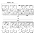
図1は、第1の実施形態を示し、本発明を適用するマルチコア・マイクロプロセッサを用いた共有メモリ型のマルチプロセッサシステムで並列計算機を構成する例を示す。 FIG. 1 shows the first embodiment and shows an example in which a parallel computer is configured by a shared memory type multiprocessor system using a multicore microprocessor to which the present invention is applied.
<ハードウェア構成>
図1において、並列計算機は複数のプロセッサモジュール(プロセッサ)P0〜P7からなるマルチプロセッサを有し、各プロセッサモジュールP0〜P7は、ひとつのモジュールに複数のプロセッサコア(図中cpu0〜15)を実装しており、ひとつのプロセッサモジュールP0には、2つのプロセッサコアが実装されている。例えば、プロセッサモジュールP0は、プロセッサコアcpu0とcpu1を備え、2つのCPUが並列して動作可能となっている。
<Hardware configuration>
In FIG. 1, the parallel computer has a multiprocessor composed of a plurality of processor modules (processors) P0 to P7, and each processor module P0 to P7 has a plurality of processor cores (cpu0 to 15 in the figure) mounted on one module. In addition, two processor cores are mounted on one processor module P0. For example, the processor module P0 includes processor cores cpu0 and cpu1, and two CPUs can operate in parallel.
そして、プロセッサコアcpu0、cpu1はそれぞれ独立した1次キャッシュメモリ(以下、1次キャッシュという)L1−0、L1−1を有する。さらに、2つのプロセッサコアcpu0、1の1次キャッシュL1−0、1は、プロセッサモジュールP0に設けたひとつの2次キャッシュメモリ(以下、2次キャッシュという)L2−0に接続されている。そして、1次キャッシュL1−0、L1−1は各プロセッサコアcpu0、1上で実行される複数のスレッド間で共有される共有記憶域(共有記憶部)として機能する。なお、本実施形態では各プロセッサコア上で実行されるスレッドは、プログラムを構成する単位(プロセスなど)であっても良いし、プログラムそのものであっても良い。また、各スレッドは同一の処理手順で構成されて異なるデータを処理し、バリア同期により並列処理を行うものであっても良いし、あるいは、各スレッドが異なる処理手順で構成されて、データを受け渡しするためにバリア同期により並列処理を行うものであっても良い。 The processor cores cpu0 and cpu1 have independent primary cache memories (hereinafter referred to as primary caches) L1-0 and L1-1, respectively. Further, the primary caches L1-0 and 1 of the two processor cores cpu0 and 1 are connected to one secondary cache memory (hereinafter referred to as secondary cache) L2-0 provided in the processor module P0. The primary caches L1-0 and L1-1 function as a shared storage area (shared storage unit) shared among a plurality of threads executed on the processor cores cpu0 and 1. In the present embodiment, the thread executed on each processor core may be a unit (process or the like) constituting the program, or may be the program itself. In addition, each thread may be configured with the same processing procedure to process different data and perform parallel processing by barrier synchronization, or each thread may be configured with a different processing procedure to deliver data. For this purpose, parallel processing may be performed by barrier synchronization.
2次キャッシュL2−0は2つのプロセッサコアcpu0、cpu1に接続されて、これらのプロセッサコアcpu0、1で共有する共有記憶域として機能する。 The secondary cache L2-0 is connected to the two processor cores cpu0 and cpu1, and functions as a shared storage area shared by these processor cores cpu0 and 1.
他の各プロセッサモジュールP1〜P7も上記プロセッサモジュールP0と同様に構成され、それぞれひとつのモジュールに2つのプロセッサコアcpuと2つの1次キャッシュL1−1〜7と、ひとつの2次キャッシュL2−1〜7を備えている。 Each of the other processor modules P1 to P7 is configured in the same manner as the processor module P0, and each module includes two processor cores cpu, two primary caches L1-1 to L7-1, and one secondary cache L2-1. ~ 7.
各プロセッサモジュールP0〜P7は、3次キャッシュメモリ(以下、3次キャッシュという)L3に接続されており、この3次キャッシュL3は各プロセッサモジュールP0〜P7間で共有する共有記憶域として機能する。なお、図1においては、プロセッサモジュールP0〜P3(cpu0〜7)でひとつの3次キャッシュL3を共有し、プロセッサモジュールP4〜P7(cpu8〜15)で異なる3次キャッシュL3を共有する例を示したが、ひとつの3次キャッシュL3をプロセッサモジュールP0〜P7で共有しても良い。また、3次キャッシュL3は、各プロセッサモジュールP0〜P7のフロントサイドバスに相当する位置に設けたが、図示はしないがバックサイドバスに設けても良い。 The processor modules P0 to P7 are connected to a tertiary cache memory (hereinafter referred to as tertiary cache) L3, and the tertiary cache L3 functions as a shared storage area shared among the processor modules P0 to P7. FIG. 1 shows an example in which the processor modules P0 to P3 (cpu0 to 7) share one tertiary cache L3 and the processor modules P4 to P7 (cpu8 to 15) share different tertiary caches L3. However, one tertiary cache L3 may be shared by the processor modules P0 to P7. Although the tertiary cache L3 is provided at a position corresponding to the front side bus of each of the processor modules P0 to P7, it may be provided on the back side bus although not shown.
さらに、プロセッサモジュールP0〜P7間で共有される3次キャッシュL3は主記憶MMに接続され、主記憶MMはプロセッサモジュールP0〜P7(cpu0〜15)で共有される。なお、主記憶MMは図示しないコントローラ(例えば、ノースブリッジ等のチップセットやスイッチ)を介して各プロセッサモジュールP0〜P7に接続され、また、各プロセッサモジュールP0〜P7は上記コントローラを介して外部記憶装置(例えば、HDD)やネットワークインターフェースに接続される。 Further, the tertiary cache L3 shared between the processor modules P0 to P7 is connected to the main memory MM, and the main memory MM is shared by the processor modules P0 to P7 (cpu0 to 15). The main memory MM is connected to the processor modules P0 to P7 via a controller (for example, a chip set or a switch such as a north bridge) (not shown), and the processor modules P0 to P7 are externally stored via the controller. It is connected to a device (for example, HDD) or a network interface.
上記共有記憶域は、プロセッサコアcpu0〜15側から主記憶MMに向けて順に1次キャッシュL1(第1の共有記憶域)、2次キャッシュL2(第2の共有記憶域)、3次キャッシュL3(第3の共有記憶域)の順で階層的に配置され、プロセッサコアから離れる(主記憶MM側)につれて共有する範囲が同一のプロセッサコア上のスレッド間から、プロセッサコア間、プロセッサモジュール間と、上位の階層になるほど広くなる階層構造となっている。 The shared storage areas are the primary cache L1 (first shared storage area), the secondary cache L2 (second shared storage area), and the tertiary cache L3 in order from the processor core cpu0-15 toward the main memory MM. (Third shared storage area) is arranged hierarchically in the order, and as it moves away from the processor core (main memory MM side), the range to be shared is between threads on the same processor core, between processor cores, between processor modules The hierarchical structure becomes wider as the higher level is reached.
そして、各プロセッサコアcpu0〜15には、プロセッサコア間で並列処理のバリア同期を行うためのハードウェアバリア同期機構100が接続される。
A hardware
<ハードウェアバリア同期機構>
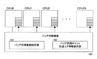
ハードウェアバリア同期機構100は、図3で示すように、各プロセッサコアcpu0〜15に接続されており、バリア同期処理を行うcpu0〜15の範囲またはグループを設定するバリア同期範囲設定部101と、プロセッサコアcpu0〜15毎にバリア同期ポイント(バリア同期の位置情報)に到達したプロセッサコアの情報を保持する同期ポイント到達情報保持部102を備えている。
<Hardware barrier synchronization mechanism>
As shown in FIG. 3, the hardware
ハードウェアバリア同期機構100は、バリア同期範囲設定部101で設定されたグループのプロセッサコアが所定のバリア同期ポイントに到達すると、同期ポイント到達情報保持部102にバリア同期ポイントに到達したことを記録し、当該グループの全てのプロセッサコアがバリア同期ポイントに到達すると、このグループの全てのプロセッサコアに同期完了を通知する。なお、この通知は、前記従来例の特開平11−312418号と同様に割り込みを用いても良いし、図3のように、プロセッサコアの1次キャッシュメモリL1等の所定の記憶域に同期完了を示す情報(例えば、終了フラグ等)を書き込むようにしても良い。
When the group of processor cores set by the barrier synchronization
<ソフトウェア構成>
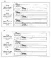
次に、図2は各プロセッサコアcpu0〜15で実行される処理の一例を示し、各cpu0〜15にそれぞれ2つのスレッドTh0〜31を割り当てて、合計32のスレッドを並列的に実行する例を示す。すなわち、ひとつのプロセッサモジュールには4つのスレッドが割り当てられ、モジュール上の2つのプロセッサコアにはそれぞれ2つのスレッドが均等に割り当てられる。
<Software configuration>
Next, FIG. 2 shows an example of processing executed by each processor core cpu0-15, and an example in which two threads Th0-31 are assigned to each cpu0-15 and a total of 32 threads are executed in parallel. Show. That is, four threads are assigned to one processor module, and two threads are assigned equally to the two processor cores on the module.
図2において、バリア同期処理を行うプロセッサモジュール(またはプロセッサコア)を同期グループGrとし、この同期グループの一例としてプロセッサモジュールP0、P1のプロセッサコアcpu0〜3のスレッドTh0〜7の8つのスレッドでバリア同期処理を行う例について以下に説明する。 In FIG. 2, a processor module (or processor core) that performs barrier synchronization processing is defined as a synchronization group Gr. As an example of this synchronization group, a barrier is formed by eight threads Th0 to 7 of processor cores cpu0 to 3 of the processor modules P0 and P1. An example of performing the synchronization process will be described below.
<バリア同期グループ>
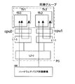
図4は、上記図2に示した同期グループGrの詳細を示す。
<Barrier synchronization group>
FIG. 4 shows details of the synchronization group Gr shown in FIG.
2つのプロセッサコアを備えたプロセッサモジュールP0、P1に8つのスレッドを割り当ててバリア同期処理を行う際には、まず、バリア同期処理を行う同期グループを、ひとつのプロセッサコア上でスレッド間のバリア同期を行う最下位階層(第1階層)のグループと、同一のプロセッサモジュール内のプロセッサコア間でバリア同期を行う第2階層(上位階層)のグループと、プロセッサモジュール間でバリア同期を行う第3階層(最上位階層)に分ける。 When eight threads are allocated to the processor modules P0 and P1 having two processor cores and barrier synchronization processing is performed, first, a synchronization group that performs barrier synchronization processing is set to barrier synchronization between threads on one processor core. , The lowest layer (first layer) group performing the barrier synchronization, the second layer (upper layer) group performing barrier synchronization between the processor cores in the same processor module, and the third layer performing barrier synchronization between the processor modules Divide into (top level).
ここで、同期グループの各階層は、各階層で共有可能な記憶域(共有記憶域)を有し、最下位階層(第1階層)は、同一のプロセッサコア上のスレッドのバリア同期を行う第1の同期グループとする。そして、同一のプロセッサコア上のスレッドが共有可能な1次キャッシュL1を共有記憶域とし、各スレッドは1次キャッシュL1に同期情報を書き込んで、同期をとる。 Here, each tier of the synchronization group has a storage area (shared storage area) that can be shared by each tier, and the lowest tier (first tier) performs the barrier synchronization of threads on the same processor core. One synchronization group is assumed. The primary cache L1 that can be shared by threads on the same processor core is used as a shared storage area, and each thread writes synchronization information to the primary cache L1 to synchronize.
次に、上位階層となる第2階層は同一のプロセッサモジュール内のプロセッサコア間でスレッドのバリア同期を行う第2の同期グループとする。このため、同一のプロセッサモジュール内のプロセッサコア間で共有可能な2次キャッシュL2を共有記憶域とし、各プロセッサコアのスレッドのうち、一つのスレッドを親スレッドとして、各プロセッサコアの親スレッドが2次キャッシュL2に同期情報を書き込んで、親スレッド間で同期をとる。 Next, the second hierarchy that is the upper hierarchy is a second synchronization group that performs thread barrier synchronization between processor cores in the same processor module. For this reason, the secondary cache L2 that can be shared between processor cores in the same processor module is used as a shared storage area, and among the threads of each processor core, one thread is a parent thread, and the parent thread of each processor core is 2 Synchronization information is written to the next cache L2 to synchronize between the parent threads.
次に、第3階層(最上位階層)はプロセッサモジュール間でスレッドのバリア同期を行う第3の同期グループとする。同一のプロセッサモジュール上の複数の親スレッドの内の一つをプロセッサモジュールの親スレッドとし、各プロセッサモジュールは親スレッド同士で同期を取る。本実施形態では、プロセッサモジュールは親スレッドはハードウェアバリア同期機構100を用いて同期を取る。
Next, the third hierarchy (the highest hierarchy) is a third synchronization group that performs thread barrier synchronization between processor modules. One of a plurality of parent threads on the same processor module is set as a parent thread of the processor module, and each processor module is synchronized with the parent thread. In the present embodiment, the processor module synchronizes the parent thread using the hardware
つまり、同期グループの各階層は、共有記憶域または共有するバリア同期機構の階層毎に設定される。 That is, each level of the synchronization group is set for each level of the shared storage area or the shared barrier synchronization mechanism.
そして、同期グループを構成するスレッドに同期グループGr内で一意の識別子としてのスレッド番号(スレッドの識別子)を割り当て、上記各階層内で最も小さいスレッド番号をもつスレッドを親スレッドとし、その他を子スレッドとする。 Then, a thread number (thread identifier) as a unique identifier in the synchronization group Gr is assigned to a thread constituting the synchronization group, the thread having the smallest thread number in each hierarchy is set as a parent thread, and the others are child threads. And
最下位階層(第1同期グループ)は、同一プロセッサコア上で複数のスレッドのバリア同期をとる階層であり、図4において、プロセッサモジュールP0のプロセッサコアcpu0には、スレッドTh0、Th1が割り当てられ、これらスレッドTh0、1はプロセッサコアcpu0上でバリア同期をとる最下位階層の同期グループを構成する。 The lowest hierarchy (first synchronization group) is a hierarchy that performs barrier synchronization of a plurality of threads on the same processor core. In FIG. 4, threads Th0 and Th1 are assigned to the processor core cpu0 of the processor module P0. These threads Th0, 1 constitute a synchronization group of the lowest hierarchy that takes barrier synchronization on the processor core cpu0.
そして、最下位階層の同期グループは、プロセッサコアcpu0の1次キャッシュL1を共有記憶域とし、図5で示すように、プロセッサコアcpu0の1次キャッシュL1−0で予め設定したキャッシュライン上に、スレッドTh0の同期情報を記憶する記憶域L100と、スレッドTh1の同期情報を記憶する記憶域L101を設定する。複数のスレッドが1つのキャッシュラインに書込みを行うことによるキャッシュラインの競合が発生しないようにするため、書き込むキャッシュラインはスレッド毎にずらして設定する。なお、同期情報としては、後述するようにバリア同期ポイントのID(同期ID番号)の他、フラグなどを用いることができる。 Then, the synchronization group of the lowest hierarchy uses the primary cache L1 of the processor core cpu0 as a shared storage area, and, as shown in FIG. 5, on the cache line preset in the primary cache L1-0 of the processor core cpu0, A storage area L100 for storing the synchronization information of the thread Th0 and a storage area L101 for storing the synchronization information of the thread Th1 are set. In order to prevent contention of cache lines due to a plurality of threads writing to one cache line, the cache line to be written is set to be shifted for each thread. As the synchronization information, a barrier synchronization point ID (synchronization ID number), a flag, or the like can be used as will be described later.
各スレッドTh0、Th1は同期情報の記憶域L100とL101の内容が一致したときに、最下位階層のバリア同期が完了したと判定する。 When the contents of the synchronization information storage areas L100 and L101 match, the threads Th0 and Th1 determine that the barrier synchronization of the lowest hierarchy has been completed.
プロセッサコアcpu1〜3上の各スレッドTh2〜Th7もプロセッサコアcpu0と同様に設定され、各プロセッサコアcpu1〜3の1次キャッシュL1−1〜3を共有記憶域として、同一プロセッサコア上のスレッドの同期情報を格納する記憶域L110、L111、L120、L121、L130、L131を各プロセッサコアの1次キャッシュL1−1〜3に設定する。 The threads Th2 to Th7 on the processor cores cpu1 to cpu3 are also set in the same manner as the processor core cpu0. The primary caches L1-1 to L1-3 of the processor cores cpu1 to c3 are used as shared storage areas, and the threads on the same processor core are set. The storage areas L110, L111, L120, L121, L130, and L131 that store the synchronization information are set in the primary caches L1-1 to L3-1 of each processor core.
そして、各プロセッサコアcpu0〜3では、スレッド番号の小さいものをそれぞれプロセッサコアの親スレッドとし、プロセッサコアcpu0の親スレッドはスレッドTh0となり、プロセッサコアcpu1の親スレッドはTh2で、同様に、プロセッサコアcpu2、3の親スレッドはスレッドTh4、Th6となる。 In each of the processor cores cpu0 to cpu3, the one having the smaller thread number is the parent thread of the processor core, the parent thread of the processor core cpu0 is the thread Th0, the parent thread of the processor core cpu1 is Th2, and similarly, the processor core The parent threads of cpu2 and 3 are threads Th4 and Th6.
第2階層(上位階層)は、同一のプロセッサモジュール内のプロセッサコア間でバリア同期を取る階層であり、図4において、プロセッサモジュールP0のプロセッサコアcpu0の親スレッドTh0と、プロセッサコアcpu1の親スレッドTh2が共有記憶域である2次キャッシュL2−0のキャッシュラインを用いて親スレッド同士の同期をとる第2の同期グループである。1次キャッシュL1−0のキャッシュと同じように複数のスレッドが同じキャッシュラインに書込みをすることにより発生するキャッシュライン競合を避けるため、スレッド毎にキャッシュラインをずらして同期の書込みを行う。 The second hierarchy (upper hierarchy) is a hierarchy that takes barrier synchronization between processor cores in the same processor module. In FIG. 4, the parent thread Th0 of the processor core cpu0 of the processor module P0 and the parent thread of the processor core cpu1 Th2 is a second synchronization group that synchronizes the parent threads using the cache line of the secondary cache L2-0 that is a shared storage area. As in the cache of the primary cache L1-0, in order to avoid cache line contention that occurs when a plurality of threads write to the same cache line, synchronous writing is performed by shifting the cache line for each thread.
例えば、プロセッサモジュールP0では、第2階層の同期グループが、プロセッサコアcpu0、1で共有する2次キャッシュL2を共有記憶域とし、図5で示すように、プロセッサコアcpu0、1で共有する2次キャッシュL2−0の予め設定したキャッシュライン上に、プロセッサコアcpu0の親スレッドTh0の同期情報を記憶する記憶域L200と、プロセッサコアcpu1の親スレッドTh2の同期情報を記憶する記憶域L201を設定する。 For example, in the processor module P0, the second-level synchronization group uses the secondary cache L2 shared by the processor cores cpu0 and 1 as a shared storage area, and the secondary shared by the processor cores cpu0 and 1 as shown in FIG. A storage area L200 for storing synchronization information of the parent thread Th0 of the processor core cpu0 and a storage area L201 for storing synchronization information of the parent thread Th2 of the processor core cpu1 are set on the cache line set in advance in the cache L2-0. .
各親スレッドTh0、Th2は同期情報の共有記憶域L200とL201の内容が一致したときに、プロセッサモジュールP0の第2階層のバリア同期が完了したと判定する。 Each of the parent threads Th0 and Th2 determines that the barrier synchronization of the second hierarchy of the processor module P0 is completed when the contents of the shared storage areas L200 and L201 of the synchronization information match.
プロセッサコアcpu2、3上の各スレッドTh4〜Th7もプロセッサモジュールP0と同様に設定され、各プロセッサコアcpu2、3の2次キャッシュL2−1を共有記憶域として、同一プロセッサモジュール内の各プロセッサコアの親スレッドTh4、Th6の同期情報を格納する記憶域L210、L211をこの2次キャッシュL2−1に設定し、共有記憶域L210とL211の内容が一致したときに、プロセッサモジュールP1の第2階層のバリア同期が完了したと判定する。 The threads Th4 to Th7 on the processor cores cpu2 and 3 are also set in the same manner as the processor module P0, and the secondary cache L2-1 of each of the processor cores cpu2 and 3 is used as a shared storage area. When the storage areas L210 and L211 for storing the synchronization information of the parent threads Th4 and Th6 are set in the secondary cache L2-1, and the contents of the shared storage areas L210 and L211 match, the second hierarchy of the processor module P1 It is determined that the barrier synchronization is completed.
第3階層(最上位階層)は、プロセッサモジュール間のバリア同期を取る階層であり、図4において、プロセッサモジュールP0のプロセッサコアcpu0の親スレッドTh0と、プロセッサモジュールP1のプロセッサコアcpu2の親スレッドTh4が同期をとる第3階層の同期グループを構成する。 The third hierarchy (the highest hierarchy) is a hierarchy that takes the barrier synchronization between the processor modules. In FIG. 4, the parent thread Th0 of the processor core cpu0 of the processor module P0 and the parent thread Th4 of the processor core cpu2 of the processor module P1 are shown. Constitutes a third-level synchronization group for synchronization.
そして、第3階層の同期グループは、ハードウェアバリア同期機構100でプロセッサモジュールの親スレッド同士のバリア同期を行うため、図3に示したバリア同期範囲設定部101に同期グループを構成するプロセッサモジュールP0、P1の親スレッドTh0、Th4が実行されるプロセッサコアcpu0、2を同期対象として設定する。
Since the third layer synchronization group performs barrier synchronization between the parent threads of the processor modules by the hardware
上記同期グループの1次キャッシュL1、2次キャッシュL2及びハードウェアバリア同期機構100の設定は、後述するように、スレッドTh0〜Th7で構成されるプログラム(ロードモジュール)により実行される。
The settings of the primary cache L1, the secondary cache L2, and the hardware
<ソフトウェアの詳細>
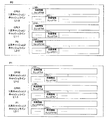
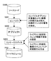
図6は、プロセッサモジュールP0、P1の同期グループで実行されるプログラム(ロードモジュール)の概要を示す。
<Details of software>
FIG. 6 shows an outline of a program (load module) executed in the synchronization group of the processor modules P0 and P1.
同期グループで実行されるプログラムPGは、使用するプロセッサコアの数など並列計算機で使用するリソースに応じてスレッドを起動し、各スレッドをプロセッサコアに割り付け、バリア同期処理の設定を行う初期設定処理PG1と、各スレッドで所定の演算を行って予め設定されたバリア同期ポイントでバリア同期を行う演算処理PG2から構成される。 The program PG executed in the synchronization group activates threads according to resources used in the parallel computer, such as the number of processor cores used, assigns each thread to a processor core, and performs an initial setting process PG1 for setting barrier synchronization processing. And an arithmetic processing PG2 that performs a predetermined calculation in each thread and performs barrier synchronization at a preset barrier synchronization point.
上記初期設定処理PG1では、使用するリソースに応じたスレッドを起動し、指示または予め設定されたプロセッサコアにそれぞれスレッドを割り付ける。その後、上記図4で示したように、スレッドの親子関係を設定し、同期グループ内でバリア同期の階層化を行いバリア同期処理の初期化を行う。 In the initial setting process PG1, a thread corresponding to the resource to be used is activated, and the thread is assigned to an instruction or a preset processor core. Thereafter, as shown in FIG. 4 above, the parent-child relationship of the threads is set, the barrier synchronization is hierarchized within the synchronization group, and the barrier synchronization processing is initialized.
このように設定された同期グループで、各プロセッサコアに割り付けられた各スレッドでは演算処理を行い、所定のバリア同期ポイントでバリア同期を実行するのである。 In the synchronization group set in this manner, each thread assigned to each processor core performs arithmetic processing and executes barrier synchronization at a predetermined barrier synchronization point.
なお、プログラムPGは、並列計算機上で実行される図示しないOSやミドルウェア上で実行されるものとする。 It is assumed that the program PG is executed on an OS or middleware (not shown) executed on the parallel computer.
<初期設定>
図7、図8は、上記図6に示したプログラム(ロードモジュール)PGのうち初期設定処理PG1の詳細を示すフローチャートで、図9、図10は上記図6に示したプログラムPGの演算処理PG2のうちバリア同期処理の詳細を示すフローチャートである。
<Initial setting>
7 and 8 are flowcharts showing the details of the initial setting process PG1 in the program (load module) PG shown in FIG. 6, and FIGS. 9 and 10 show the calculation process PG2 of the program PG shown in FIG. 4 is a flowchart showing details of the barrier synchronization processing.
図7において、初期設定処理PG1は、並列計算機の任意のプロセッサモジュールで実行され、まず、S1では、使用するプロセッサコア(CPU)の数Nと、起動するスレッドの数Mを入力する(ただし、M、Nは自然数)。この入力は、例えば図示しないネットワークを介して管理コンソールなどから管理者などが入力し、初期設定処理PG1は演算処理PG2を実行するプロセッサコアの数Nとスレッドの数Mを設定する。そして、プロセッサコア数Nとスレッド数Mを主記憶MMの所定の記憶域に格納しておく。 In FIG. 7, the initial setting process PG1 is executed by an arbitrary processor module of the parallel computer. First, in S1, the number N of processor cores (CPU) to be used and the number M of threads to be activated are input (however, M and N are natural numbers). This input is input by an administrator or the like from a management console or the like via a network (not shown), for example, and the initial setting process PG1 sets the number N of processor cores and the number M of threads for executing the calculation process PG2. Then, the number N of processor cores and the number M of threads are stored in a predetermined storage area of the main memory MM.
そしてS2で、初期設定処理PG1は、プロセッサコア数Nに対応するプロセッサコアの番号(図中CPUID=プロセッサコアの識別子)を図示しないOSやミドルウェアなどから取得する。例えば、上記図4の例では、プロセッサコア数N=4、スレッド数M=8となり、プロセッサモジュールP0、P1を使用する場合には、プロセッサコア番号は0〜3となる。 In S2, the initial setting process PG1 obtains a processor core number (CPUID = processor core identifier in the figure) corresponding to the number N of processor cores from an OS or middleware not shown. For example, in the example of FIG. 4, the number of processor cores N = 4 and the number of threads M = 8. When the processor modules P0 and P1 are used, the processor core numbers are 0 to 3.
次に、S3では、設定されたスレッドの数Mがプロセッサコアの数Nより大きいか否かを判定する。換言すれば、マルチスレッド処理かシングルスレッド処理かを判定する。 Next, in S3, it is determined whether or not the set number M of threads is larger than the number N of processor cores. In other words, it is determined whether it is multithread processing or single thread processing.
ひとつのプロセッサコアに複数のスレッドを割り当てるマルチスレッド処理の場合にはS4に進み、ひとつのプロセッサコアにひとつのスレッド割り当てるシングルスレッド処理であればS11に進む。このシングルスレッド処理を行うS11〜S13は前記従来例と同様であり、上記S1、S2で取得したプロセッサコア番号にそれぞれ1つずつスレッドを割り当て、プロセッサコア番号毎に割り当てたスレッドを起動する(S11)。 If the multi-thread process assigns a plurality of threads to one processor core, the process proceeds to S4. If the single thread process assigns one thread to one processor core, the process proceeds to S11. Steps S11 to S13 for performing the single thread processing are the same as in the conventional example. One thread is assigned to each of the processor core numbers acquired in S1 and S2, and the assigned thread is activated for each processor core number (S11). ).
そして、プロセッサコア番号の小さい順にスレッド番号Th(x)を割り当て(S12)、ハードウェアバリア同期機構100に、同期するスレッドを実行するプロセッサコア番号を通知し、演算処理PG2でハードウェアバリア同期機構100のみを使用してバリア同期処理を行うように設定する(S13)。
Then, the thread number Th (x) is assigned in ascending order of the processor core number (S12), the hardware
一方、マルチスレッド処理の場合には、S4に進んで、上記S1で設定されたプロセッサコア数N(プロセッサコア番号)とスレッドの数Mから、1つのプロセッサコアにM/Nのスレッド数を割り当てる。ここでは、プロセッサコア番号=i〜i+(N−1)に、M/Nの商に対応する数のスレッド数を割り当て、さらにM/Nの結果に余りがあればプロセッサコア番号の小さい順に余りのスレッド数を一つずつ割り当てる。そしてS5で、各スレッドを起動する。 On the other hand, in the case of multi-thread processing, the process proceeds to S4, and the number of M / N threads is assigned to one processor core from the number N of processor cores (processor core number) and the number M of threads set in S1. . Here, the number of threads corresponding to the quotient of M / N is assigned to processor core number = i to i + (N−1), and if there is a remainder in the result of M / N, the remainder is in ascending order of processor core number. Allocate one thread at a time. In S5, each thread is activated.
次に、S6では、プロセッサコア番号=i〜i+(N−1)に割り当てた各スレッドにそれぞれスレッド番号Th(x)を割り当てる。この割り当ては、プロセッサコア番号の小さい順に、0番から(N−1)番を割り当てる。なお、このプロセッサコア番号とスレッド番号の割り当ての結果は、主記憶MMなどの所定の記憶域に格納しておく。
Next, in S6, a thread number Th (x) is assigned to each thread assigned to the processor core number = i to i + (N-1). In this assignment,
例えば、上記図4の例では、N=4、i=0であるので、プロセッサコア番号=0〜3に、スレッド数=2を割り当て、プロセッサコア番号=0(cpu0)のスレッドにスレッド番号(スレッドID)Th0、Th1を割り当て、プロセッサコア番号=1(cpu1)のスレッドにスレッド番号Th2、Th3を割り当て、プロセッサコア番号=2、3には同様にTh4〜7を割り当てる。これにより、各プロセッサコアで実行されるスレッド番号とプロセッサコア番号の対応関係が決まり、どのプロセッサコアでどのスレッド番号が実行されるかが決定される。 For example, in the example of FIG. 4, since N = 4 and i = 0, the number of threads = 2 is assigned to the processor core number = 0 to 3, and the thread number (0) is assigned to the thread of the processor core number = 0 (cpu0). Thread IDs Th0 and Th1 are assigned, thread numbers Th2 and Th3 are assigned to threads with a processor core number = 1 (cpu1), and Th4 to 7 are assigned to processor core numbers = 2 and 3 in the same manner. As a result, the correspondence between the thread number executed in each processor core and the processor core number is determined, and which thread number is executed in which processor core.
次に、S7では同期グループGrの階層構造を決定するため、使用するプロセッサコア数Nから、次式によりプロセッサモジュール数Kを求める。 Next, in S7, in order to determine the hierarchical structure of the synchronization group Gr, the number K of processor modules is obtained from the number N of processor cores used by the following equation.
K=N/CORE ………(1)
ただし、COREは一つのプロセッサモジュールが有するプロセッサコアの数を示し、本実施形態の例では、CORE=2である。なお、汎用性を持たせる場合には、このS7でひとつのプロセッサモジュールが有するプロセッサコアの数Nを入力するようにしてもよい。
K = N / CORE (1)
However, CORE indicates the number of processor cores included in one processor module, and CORE = 2 in the example of the present embodiment. In order to provide general versatility, the number N of processor cores included in one processor module may be input in S7.
そして、S8では、上記S7で求めた使用プロセッサモジュール数Kから次式により、図4に示したバリア同期グループGrの階層数Fを決定する。 In S8, the number F of layers in the barrier synchronization group Gr shown in FIG. 4 is determined from the number K of used processor modules obtained in S7 by the following equation.
F=K+1 ………(2)
例えば、図4の例では、使用プロセッサモジュール数K=4/2=2であるからバリア同期グループGrは階層数F=3となり、1次キャッシュL1で同一プロセッサコアのスレッドの同期を取る第1の同期グループと、2次キャッシュL2で同一プロセッサモジュールの親スレッド同士のバリア同期を取る第2のバリアループと、ハードウェアバリア同期機構100によりプロセッサモジュールP0、P1の親スレッド同士の同期を取る第3の同期グループの3階層となる。
F = K + 1 (2)
For example, in the example of FIG. 4, since the number of used processor modules K = 4/2 = 2, the barrier synchronization group Gr becomes the number of hierarchies F = 3 and the first cache L1 synchronizes threads of the same processor core. Synchronization group, the second barrier loop for synchronizing the parent threads of the same processor module in the secondary cache L2, and the hardware
なお、上記(2)式は2つのプロセッサコアcpu0、1で一つの2次キャッシュL2−0を共有する場合のものであり、プロセッサコアやプロセッサモジュールが2次キャッシュL2、3次キャッシュL3を共有する形態に応じて上記(2)式を適宜変更すればよい。また、階層数Fを自動的に計算できない場合や、計算された階層数Fを変更したい場合には、管理コンソールなどから階層数Fを入力するようにしても良い。 The above equation (2) is for the case where two processor cores cpu0 and 1 share one secondary cache L2-0, and the processor core and processor module share the secondary cache L2 and tertiary cache L3. What is necessary is just to change the said (2) Formula suitably according to the form to do. If the number of hierarchies F cannot be calculated automatically, or if it is desired to change the calculated number of hierarchies F, the number of hierarchies F may be input from a management console or the like.
S9では、上記同期グループGrの階層数Fに基づいて、第1階層(第1同期グループ)から第2階層(第2同期グループ)までのバリア同期の設定を行う。つまり、各階層毎にバリア同期を行う共有記憶域(キャッシュなど)に同期情報を格納する領域を設定する。この処理は、図8のフローチャートに基づいて行われ、本実施形態では、第3階層をハードウェアバリア同期機構100で行うため、S9の各階層のバリア同期の設定は、第1階層と第2階層のみとしている。
In S9, based on the number of hierarchies F of the synchronization group Gr, barrier synchronization is set from the first hierarchy (first synchronization group) to the second hierarchy (second synchronization group). That is, an area for storing synchronization information is set in a shared storage area (cache or the like) that performs barrier synchronization for each layer. This process is performed based on the flowchart of FIG. 8, and in the present embodiment, the third hierarchy is performed by the hardware
図8において、S20ではスレッド番号Th(j)を参照する変数jを0に初期化し、S21では第i階層を参照する変数iを1に初期化する。 In FIG. 8, a variable j that refers to the thread number Th (j) is initialized to 0 in S20, and a variable i that refers to the i-th layer is initialized to 1 in S21.
S22では、現在のjの値に応じてスレッド番号Th(j)の情報を取得する。S23では、現在の変数iの値に応じて第i階層で同期するスレッドの情報(同一階層で同期するスレッド番号など)を取得する。 In S22, the thread number Th (j) information is acquired according to the current value of j. In S23, information on threads synchronized in the i-th hierarchy (such as thread numbers synchronized in the same hierarchy) is acquired according to the current value of the variable i.
S24では、変数i=1であるか、すなわち、第1階層であるか否かを判定して、第1階層であればS26に進む一方、第1階層よりも上位の階層であればS25に進む。 In S24, it is determined whether or not the variable i = 1, that is, whether it is the first hierarchy. If it is the first hierarchy, the process proceeds to S26, while if it is a hierarchy higher than the first hierarchy, the process proceeds to S25. move on.
S25では、現在参照しているスレッド(Th(j))が、一つ下位の階層(i−1階層)で親スレッドであるか否かを判定する。参照しているスレッドTh(j)が一つ下位の階層で親スレッドであればS26に進み、そうでなければS30に進んで次のループに進む。 In S25, it is determined whether or not the currently referred thread (Th (j)) is a parent thread in the next lower hierarchy (i-1 hierarchy). If the thread Th (j) being referred to is a parent thread in the lower hierarchy, the process proceeds to S26, otherwise proceeds to S30 and proceeds to the next loop.
S26では、現在参照している第i階層を構成するスレッドの中で、参照しているスレッドのスレッド番号Th(j)が最も小さいか否かを判定する。スレッド番号Th(j)が同一階層内で最も小さければこのスレッド番号Th(j)のスレッドを第i階層の親スレッドとし(S27)、そうでなければ第i階層の子スレッドとする(S28)。 In S26, it is determined whether or not the thread number Th (j) of the referring thread is the smallest among the threads constituting the i-th layer currently referenced. If the thread number Th (j) is the smallest in the same hierarchy, the thread of this thread number Th (j) is set as the parent thread in the i-th hierarchy (S27), otherwise, it is set as the child thread in the i-th hierarchy (S28). .
上記S27、S28で同一階層内でスレッドの親子関係を設定すると、S29で第i階層に対応する共有記憶域に、親スレッドの同期情報を格納する領域と、子スレッドの同期情報を格納する領域を設定する。 When the parent-child relationship of the threads is set in the same hierarchy in S27 and S28, the area for storing the synchronization information of the parent thread and the area for storing the synchronization information of the child thread are stored in the shared storage area corresponding to the i-th hierarchy in S29. Set.
現在参照している階層に関する処理が完了すると、S30に進んで次の階層を参照するため、変数iに1を加算する。そして、S31では、加算後の変数iで参照する階層が最上位階層(本実施形態では第3階層)に達したか否かを判定する。最上位階層に達した場合には次のスレッドを参照するためにS32へ進み、最上位階層に達していない場合には次の階層について共有記憶域を用いたバリア同期を設定するため、S23に戻る。 When the processing related to the currently referenced hierarchy is completed, the process proceeds to S30, and 1 is added to the variable i to refer to the next hierarchy. In S31, it is determined whether or not the hierarchy referenced by the variable i after addition has reached the highest hierarchy (the third hierarchy in the present embodiment). If the highest hierarchy is reached, the process proceeds to S32 to refer to the next thread. If the highest hierarchy is not reached, the barrier synchronization using the shared storage area is set for the next hierarchy. Return.
同期グループGrの階層が最上位階層に達したS32では、次のスレッドについて同期グループの設定を行うため、参照するスレッド番号Th(j)の変数jに1を加算して、次のスレッド番号を参照するように設定する。 In S32 when the hierarchy of the synchronization group Gr reaches the highest hierarchy, 1 is added to the variable j of the thread number Th (j) to be referred to in order to set the synchronization group for the next thread, and the next thread number is set. Set to reference.
そして、S33では加算後の変数jが最後のスレッド番号Th(M−1)を超えたか否かを判定し、最後のスレッド番号Th(M−1)を超えていなければ次のスレッドを参照するためにS22へ戻る。一方、最後のスレッド番号Th(M−1)を超えていればS20〜S33のサブルーチンを終了して図7のS10に進む。 In S33, it is determined whether or not the variable j after addition exceeds the last thread number Th (M-1). If the variable j does not exceed the last thread number Th (M-1), the next thread is referred to. Therefore, the process returns to S22. On the other hand, if it exceeds the last thread number Th (M−1), the subroutine of S20 to S33 is terminated and the process proceeds to S10 of FIG.
図7のS10では、プロセッサモジュール間でスレッドのバリア同期を取る第3階層(第3同期グループ)の設定を行う。本実施形態では、第3階層を最上位階層として、第3階層のバリア同期をハードウェアバリア同期機構100で行うため、同期グループGrのプロセッサモジュールで実行されるスレッドのうち、各プロセッサモジュールでスレッド番号が最も小さいものをそれぞれ選択する。そして、選択したスレッドを実行するプロセッサコアをバリア同期範囲設定部101に設定し、第3階層のバリア同期を設定する。
In S10 of FIG. 7, the third hierarchy (third synchronization group) is set for thread barrier synchronization between the processor modules. In the present embodiment, since the third hierarchy is the highest hierarchy, and the barrier synchronization of the third hierarchy is performed by the hardware
上記図7、図8のフローチャートによるバリア同期の初期設定を、図4の例で行った場合を以下に示す。 The case where the initial setting of the barrier synchronization according to the flowcharts of FIGS. 7 and 8 is performed in the example of FIG. 4 is shown below.
図4の例では、使用プロセッサコア数N=4、スレッドの数M=8であるのでマルチスレッド処理となり、一つのプロセッサコアに2つずつスレッドを割り当てる。4つのプロセッサコアをプロセッサモジュールP0、P1に割り当て、使用するプロセッサコア番号はcpu0〜cpu3となる(S1〜S3)。 In the example of FIG. 4, since the number of processor cores used N = 4 and the number of threads M = 8, multithread processing is performed, and two threads are assigned to one processor core. Four processor cores are assigned to the processor modules P0 and P1, and the processor core numbers to be used are cpu0 to cpu3 (S1 to S3).
各プロセッサコアcpu0〜cpu3に割り当てたスレッドに、プロセッサコア番号の小さいものから順にスレッド番号Thを割り当てる。この結果、図4で示すように、スレッドTh0〜Th7が設定される(S4〜S6)。 Thread numbers Th are assigned to threads assigned to the processor cores cpu0 to cpu3 in order from the smallest processor core number. As a result, as shown in FIG. 4, threads Th0 to Th7 are set (S4 to S6).
次に、同期グループGrの階層は、プロセッサモジュールのプロセッサコア数COREが2であるので、使用プロセッサモジュール数は2となり階層数F=3となり、バリア同期グループは3階層のバリア同期グループで構成される(S8)。 Next, since the number of processor cores CORE of the processor module is 2 in the hierarchy of the synchronization group Gr, the number of processor modules used is 2 and the hierarchy number F = 3, and the barrier synchronization group is configured by a 3-level barrier synchronization group. (S8).
次に、図8のバリア同期設定のサブルーチンにて、各スレッド毎に各階層の設定を行う。 Next, each layer is set for each thread in the barrier synchronization setting subroutine of FIG.
まず、i=1、j=0であるから(S20、S21)、スレッドTh0について第1階層の設定を行う。スレッドTh0はプロセッサコアcpu0で実行され、第1階層となる同一プロセッサコアcpu0で同期させるスレッドはTh1がある(S22、S23)。 First, since i = 1 and j = 0 (S20, S21), the first layer is set for the thread Th0. The thread Th0 is executed by the processor core cpu0, and the thread to be synchronized by the same processor core cpu0 as the first hierarchy is Th1 (S22, S23).
現在参照しているスレッドTh0のスレッド番号0と第1階層の他のスレッド番号1を比較し、自スレッドのスレッド番号方が小さいため、このスレッドTh0は第1階層の親スレッドとなる(S26、S27)。
The
そして、第1階層に対応する共有記憶域として1次キャッシュL1−0の所定のキャッシュラインの先頭に同期情報を格納する記憶域L100を設定し(S29)、第1階層の設定を終了する。 Then, a storage area L100 for storing synchronization information is set at the head of a predetermined cache line of the primary cache L1-0 as a shared storage area corresponding to the first hierarchy (S29), and the setting of the first hierarchy is completed.
次に図8のS23に戻り、i=2として第2階層についてスレッドTh0の設定を行う。第2階層は同一プロセッサモジュール内のプロセッサコア間のバリア同期であり、同期するスレッドは、図4で示すように、cpu1のスレッドTh2、Th3となる(S23)。 Next, returning to S23 of FIG. 8, the thread Th0 is set for the second hierarchy with i = 2. The second hierarchy is barrier synchronization between processor cores in the same processor module, and the threads to be synchronized are threads Th2 and Th3 of cpu1 as shown in FIG. 4 (S23).
次に、現在参照しているスレッドTh0は、一つ下の階層で親スレッドであるので、プロセッサコアcpu1のスレッドTh2、Th3とスレッド番号を比較する。この結果スレッドTh0のスレッド番号0が最小であるので、第2階層の親スレッドに設定される(S26、S27)。
Next, since the currently referred thread Th0 is a parent thread in the next lower hierarchy, the thread numbers of the threads Th2 and Th3 of the processor core cpu1 are compared. As a result, since the
そして、第2階層に対応する共有記憶域として2次キャッシュL2−0の所定のキャッシュラインの先頭に、同期情報を格納する記憶域L200を設定し(S29)、第2階層の設定を終了する。この後、変数iをインクリメントするとi=3となるので、次の参照スレッドをTh1としてS22へ戻る。 Then, a storage area L200 for storing synchronization information is set at the head of a predetermined cache line of the secondary cache L2-0 as a shared storage area corresponding to the second hierarchy (S29), and the setting of the second hierarchy is completed. . Thereafter, if the variable i is incremented, i = 3, so that the next reference thread is set to Th1 and the process returns to S22.
上記と同様に同一階層内の情報取得し、第1階層から順にバリア同期の設定を行う。このスレッドTh1は第1階層ではスレッド番号1が最小ではないので、第1階層の子スレッドに設定され、第1階層に対応する1次キャッシュL1−0の所定のキャッシュラインの2番目の記憶域L101に同期情報を格納するよう設定する(S29)。
Similarly to the above, information in the same hierarchy is acquired, and the barrier synchronization is set in order from the first hierarchy. Since this thread Th1 is not the
第2階層においては、一つ下位の階層(第1階層)では親スレッドではないので、第2階層の同期スレッドには設定されずに設定を終了する。 In the second hierarchy, since it is not the parent thread in the next lower hierarchy (first hierarchy), the setting is finished without being set in the synchronization thread in the second hierarchy.
他のスレッドTh2〜Th7も上記と同様に各階層でバリア同期の設定が行われ、最後に各プロセッサモジュールP0、P1の親スレッドであるTh0とTh4をハードウェアバリア同期機構100に同期グループとして設定し、最上位階層の第3階層の設定を終了する。なお、ハードウェアバリア同期機構100が行う第3階層の同期完了の条件は、同一階層内のスレッドTh0とスレッドTh4のバリア同期が完了したときが同期完了の条件である。
The other threads Th2 to Th7 are also set for barrier synchronization in each layer in the same manner as above, and finally the parent threads Th0 and Th4 of the processor modules P0 and P1 are set as a synchronization group in the hardware
<バリア同期処理>
上記図7、図8の初期設定によりスレッドを割り当てられたプロセッサモジュールで行われる演算処理のうち、バリア同期処理について図9、図10のフローチャートを参照しながら説明する。図9は最下位階層(第1階層)で行われる処理で、図10は上位階層(第2階層)で行われる処理を示し、各処理は所定の周期で実行される。なお、最上位階層となる第3階層はハードウェアバリア同期機構100を用いるため、フローチャートは省略した。
<Barrier synchronization processing>
Of the arithmetic processing performed by the processor module to which the thread is assigned by the initial setting in FIGS. 7 and 8, the barrier synchronization processing will be described with reference to the flowcharts in FIGS. FIG. 9 shows processing performed in the lowest layer (first layer), and FIG. 10 shows processing performed in the upper layer (second layer). Each processing is executed at a predetermined cycle. Note that the third layer, which is the highest layer, uses the hardware
図9において、第1階層の同期グループの処理は、まず、S41で演算処理が所定の同期ポイントに到達していればS42以降のバリア同期処理へ進み、同期ポイントに達していなければ演算処理を継続する。 In FIG. 9, in the synchronization group processing of the first hierarchy, first, if the calculation process has reached a predetermined synchronization point in S41, the process proceeds to the barrier synchronization process after S42. If the calculation process has not reached the synchronization point, the calculation process is performed. continue.
同期ポイントに到達したS42では、第1階層の共有記憶域である1次キャッシュL1の所定の記憶域に同期ポイントのID(同期位置の識別子=同期情報)を書き込む。 In S42 that has reached the synchronization point, the ID of the synchronization point (synchronization position identifier = synchronization information) is written in a predetermined storage area of the primary cache L1, which is the shared storage area of the first hierarchy.
S43では、自スレッドが親スレッドであるか否かを判定し、親スレッドの場合はS44以降の処理へ進み、子スレッドの場合にはS52に進んで、同一の第1階層の親スレッドから同期ポイントに達した通知(同期完了通知)を待ち、通知を受けると同期処理を終了して次の演算処理に進む。なお、この同期完了の通知は、上述のように前記記憶域に同期完了を示す情報を書き込むことで行われる。 In S43, it is determined whether or not the own thread is a parent thread. If the thread is a parent thread, the process proceeds to S44 and the subsequent processes. If the thread is a child thread, the process proceeds to S52 to synchronize from the same first-level parent thread. The system waits for a notification reaching the point (synchronization completion notification), and upon receiving the notification, the synchronization processing is terminated and the processing proceeds to the next calculation processing. This synchronization completion notification is performed by writing information indicating synchronization completion to the storage area as described above.
親スレッドの場合のS44では、1次キャッシュL1の所定のキャッシュラインから、同一の第1階層の子スレッドの同期ポイントIDを読み込み、S45で親スレッドの同期ポイントIDと全ての子スレッドの同期ポイントIDが一致した場合にはバリア同期が完了したと判定してS46に進む。なお、一致しない場合には全ての子スレッドの同期ポイントIDが親スレッドの同期ポイントIDと一致するのを待つ。 In S44 in the case of the parent thread, the synchronization point ID of the same first-level child thread is read from a predetermined cache line of the primary cache L1, and in S45, the synchronization point ID of the parent thread and the synchronization points of all the child threads are read. If the IDs match, it is determined that the barrier synchronization has been completed, and the process proceeds to S46. If they do not match, the process waits for the synchronization point IDs of all the child threads to match the synchronization point IDs of the parent thread.
S46では、上記初期設定のS8で求めた同期グループの階層数Fが1より大きい、換言すれば上位階層があるか否かを判定し、上位階層があればS47に進み、第1階層のみであればS50に進む。 In S46, it is determined whether the synchronization group hierarchy number F obtained in the initial setting S8 is greater than 1, in other words, whether or not there is an upper hierarchy. If there is an upper hierarchy, the process proceeds to S47, and only the first hierarchy is present. If so, the process proceeds to S50.
S47では、上位階層(第2階層)へ第1階層のバリア同期が完了したことを通知する。次いで、S48では図10に示す上位階層(第2階層)のバリア同期処理を行う。 In S47, the upper layer (second layer) is notified that the barrier synchronization of the first layer has been completed. Next, in S48, barrier synchronization processing of the upper layer (second layer) shown in FIG. 10 is performed.
S49では、上位階層(第2階層)のバリア同期処理から同期完了の通知を待ち、上位階層から同期完了の通知を受けるとS50に進んで、全ての子スレッドにバリア同期の完了を通知する。 In S49, the notification of the completion of synchronization is waited from the upper layer (second layer) barrier synchronization processing. When the notification of the completion of synchronization is received from the upper layer, the process proceeds to S50, and the completion of the barrier synchronization is notified to all the child threads.
そして、S51で各子スレッドへの完了通知を順次行って、全ての子スレッドへの通知が完了するとバリア同期処理を終了し、次の演算処理を開始する。 Then, in S51, notification of completion to each child thread is sequentially performed. When notification to all the child threads is completed, the barrier synchronization processing is terminated and the next calculation processing is started.
すなわち、図4において、スレッドTh0の場合、第1階層の親スレッドであるので、自スレッドが同期を完了すると、図5の1次キャッシュL1−0の記憶域L100に同期ポイントIDを書き込んで、子スレッドであるスレッドTh1の記憶域L101を監視する。 That is, in FIG. 4, since the thread Th0 is the parent thread of the first hierarchy, when the own thread completes synchronization, the synchronization point ID is written in the storage area L100 of the primary cache L1-0 in FIG. The storage area L101 of the thread Th1, which is a child thread, is monitored.
そして、子スレッドTh1の記憶域L101に同一の同期ポイントIDが書き込まれると、同期グループの階層数Fが2以上であるかを判定してから後述する図10に示す第2階層のバリア同期処理を行う。 Then, when the same synchronization point ID is written in the storage area L101 of the child thread Th1, it is determined whether or not the synchronization group hierarchy number F is 2 or more, and then the second hierarchy barrier synchronization processing shown in FIG. I do.
図10の処理を終了すると、第1階層の上位階層である第2階層からの同期完了の通知を待つ。第2階層からの同期完了通知を受けると、全ての子スレッド(この場合ではTh1)に同期完了を通知し、子スレッドが同期完了を受信したのを確認するとバリア同期処理を完了し、次の演算処理を開始する。各スレッドは上記処理をバリア同期ポイントに到達する度に実行することで同期を取る。 When the process of FIG. 10 is finished, the notification of synchronization completion from the second hierarchy, which is the upper hierarchy of the first hierarchy, is waited for. When the synchronization completion notification is received from the second layer, all the child threads (Th1 in this case) are notified of the synchronization completion. Upon confirming that the child thread has received the synchronization completion, the barrier synchronization processing is completed. Start arithmetic processing. Each thread is synchronized by executing the above process every time it reaches the barrier synchronization point.
次に、図10の上位階層(第2階層)のバリア同期処理について説明する。 Next, barrier synchronization processing of the upper hierarchy (second hierarchy) in FIG. 10 will be described.
図10の処理は、下位階層のバリア同期が完了してから実行されるもので、S61では自スレッドが同期ポイントに達しているので、第2階層に対応する共有記憶域である2次キャッシュL2の所定の記憶域に同期ポイントIDを書き込む。 The processing in FIG. 10 is executed after barrier synchronization in the lower hierarchy is completed. Since the own thread has reached the synchronization point in S61, the secondary cache L2 which is a shared storage area corresponding to the second hierarchy is executed. The synchronization point ID is written in the predetermined storage area.
そして、S62でスレッドの親子関係を判定し、親スレッドであれば、同期すべき子スレッドの2次キャッシュL2の記憶域を監視し、全ての子スレッドの同期ポイントIDが一致したら第2階層及び下位階層の同期が完了したと判定し上位階層のバリア同期処理(ここではハードウェアバリア同期機構100)に同期完了を通知する(S63〜S65)。この通知は、2次キャッシュL2に同期完了を示す情報を書き込むことで行われる。 Then, in S62, the parent-child relationship of the threads is determined, and if it is a parent thread, the storage area of the secondary cache L2 of the child thread to be synchronized is monitored, and if the synchronization point IDs of all the child threads match, the second hierarchy and It is determined that the synchronization of the lower layer has been completed, and the completion of synchronization is notified to the barrier synchronization process of the upper layer (here, the hardware barrier synchronization mechanism 100) (S63 to S65). This notification is performed by writing information indicating the completion of synchronization in the secondary cache L2.
次に、S66では、上位階層(第3階層)のバリア同期処理(ハードウェアバリア同期機構100)から同期完了の通知を待ち、第3階層から同期完了の通知を受けると、S67で全ての子スレッドにバリア同期完了を通知し、S68で全子スレッドが同期完了を受信すると上位階層のバリア同期処理を完了し、図9の処理に戻る。 Next, in S66, a synchronization completion notification is waited from the upper layer (third layer) barrier synchronization processing (hardware barrier synchronization mechanism 100). The thread is notified of the completion of the barrier synchronization, and when all the child threads receive the synchronization completion in S68, the upper layer barrier synchronization processing is completed and the processing returns to the processing in FIG.
上記バリア同期処理を、図4に示した例で行った場合は、次のようになる。まず、図9の処理で、第1階層及び第2階層の親スレッドであるスレッドTh0がバリア同期ポイントに到達すると、図5の1次キャッシュL1−0の記憶域L100に同期ポイントIDを書き込み(S42)、子スレッドTh1の記憶域L101を監視して同期ポイントIDが一致するのを待つ(S45)。記憶域L100、L101の同期ポイントIDが一致すると第1階層の同期完了を第2階層へ通知する。これにより、同一プロセッサコアcpu0内のスレッドTh0、1の同期が完了する。 When the barrier synchronization process is performed in the example shown in FIG. First, in the process of FIG. 9, when the thread Th0 that is the parent thread of the first hierarchy and the second hierarchy reaches the barrier synchronization point, the synchronization point ID is written into the storage area L100 of the primary cache L1-0 in FIG. In step S42, the storage area L101 of the child thread Th1 is monitored to wait for the synchronization point IDs to match (S45). When the synchronization point IDs of the storage areas L100 and L101 match, the second hierarchy is notified of the completion of synchronization in the first hierarchy. Thereby, the synchronization of the threads Th0 and 1 in the same processor core cpu0 is completed.
その後、図10の処理に移り第2階層のバリア同期処理を行う。スレッドTh0は、同期ポイントに到達したので第2階層バリア同期処理に対応する2次キャッシュL2−0の記憶域L200に同期ポイントIDを書き込み(S62)、子スレッドTh2の記憶域L201を監視して同期ポイントIDが一致するのを待つ(S65)。記憶域L200、L201の同期ポイントIDが一致すると第2階層のバリア同期が完了する。そして、第2階層の同期完了を第3階層(ハードウェアバリア同期機構100)へ通知する。 Thereafter, the processing moves to the processing of FIG. 10 and the second layer barrier synchronization processing is performed. Since the thread Th0 has reached the synchronization point, the synchronization point ID is written in the storage area L200 of the secondary cache L2-0 corresponding to the second hierarchy barrier synchronization processing (S62), and the storage area L201 of the child thread Th2 is monitored. Wait until the synchronization point IDs match (S65). When the synchronization point IDs of the storage areas L200 and L201 match, the second layer barrier synchronization is completed. Then, the completion of the synchronization of the second hierarchy is notified to the third hierarchy (hardware barrier synchronization mechanism 100).
この後、第2階層のバリア同期処理は、ハードウェアバリア同期機構100からの同期完了通知を待ち(S68)、ハードウェアバリア同期機構100が第3階層のスレッドTh0とスレッドTh4の同期完了を検知すると、第2階層のスレッドTh0、4に同期完了を通知する。この同期完了通知に基づいて第2階層のスレッドTh0は、第2階層の子スレッドTh2に同期完了の通知を行い、全ての子スレッドに同期完了通知を送ると第2階層のバリア同期処理を完了する(S69、S70)。
Thereafter, the barrier synchronization processing of the second layer waits for a synchronization completion notification from the hardware barrier synchronization mechanism 100 (S68), and the hardware
その後、図9の第1階層のバリア同期処理に戻り、第1階層のバリア同期処理は、第2階層のバリア同期処理から同期完了の通知を受けたので(S48)、第1階層の子スレッドTh1に同期完了を通知し、全ての子スレッドに通知を行うと、バリア同期処理を完了する。 Thereafter, the process returns to the barrier synchronization process of the first layer in FIG. 9, and since the barrier synchronization process of the first layer has received a notification of synchronization completion from the barrier synchronization process of the second layer (S48), the child thread of the first layer When the completion of synchronization is notified to Th1 and all child threads are notified, the barrier synchronization processing is completed.
以上のように、プロセッサコア内とプロセッサモジュール内で、プロセッサコアに近い共有記憶域から主記憶MM側に階層化した同期グループを複数設定し、これら同期グループ毎にバリア同期処理を行い、最上位層のみハードウェアバリア同期機構100を用いることで、マルチコア・マイクロプロセッサを用いてひとつのプロセッサコアでマルチスレッド処理により並列処理を行う場合であっても、多数のスレッドの同期を確実に取ることができる。
As described above, in the processor core and in the processor module, multiple synchronization groups that are hierarchized from the shared storage area close to the processor core to the main memory MM side are set, and barrier synchronization processing is performed for each of these synchronization groups. By using the hardware
したがって、既存のハードウェアバリア同期機構100を用いながらマルチコア・マイクロプロセッサを用いたマルチスレッドの並列処理においてバリア同期を行うことが可能となるので、並列計算機の価格が上昇するのを防ぎながら、多数のスレッド間のバリア同期を実現できるのである。
Therefore, since barrier synchronization can be performed in parallel processing of multithreads using a multi-core microprocessor while using the existing hardware
そして、同一プロセッサコアのスレッドの同期には、プロセッサコア内の1次キャッシュL1を用い、同一プロセッサモジュール内のスレッドの同期には、プロセッサモジュール内の2次キャッシュL2を用いることで、各親スレッドから最も遅延の少ない共有記憶域にアクセスすることで、処理の高速化を図ることができ、並列処理の高速化を図ることができるのである。 Each parent thread can be synchronized by using the primary cache L1 in the processor core for synchronizing threads of the same processor core, and using the secondary cache L2 in the processor module for synchronizing threads in the same processor module. Thus, by accessing the shared storage area with the least delay, the processing speed can be increased, and the parallel processing speed can be increased.
また、バリア同期処理に用いる共有記憶域を、階層毎に異なる記憶装置(キャッシュまたは主記憶)に配置することで、異なる同期グループで記憶域が競合するのを確実に回避でき、バリア同期処理を正確に行うことが可能となるのである。 In addition, by arranging the shared storage area used for barrier synchronization processing in different storage devices (cache or main memory) for each tier, it is possible to reliably avoid storage area contention in different synchronization groups, and barrier synchronization processing It is possible to perform accurately.
さらに、プロセッサコア上あるいはプロセッサコア間でバリア同期を行う場合は、1次キャッシュL1や2次キャッシュL2などプロセッサコアからのアクセスに関するレイテンシイが少ない共有記憶域を用いたソフトウェアでバリア同期を行い、プロセッサモジュール間のバリア同期などプロセッサコアから遠くアクセスに関するレイテンシイが大きくなるバリア同期にハードウェアバリア同期機構100を用いることで、最下位階層から最上位階層までのバリア同期を高速に行うことが可能となる。
Further, when barrier synchronization is performed on or between processor cores, barrier synchronization is performed with software using a shared storage area with low latency related to access from the processor core such as the primary cache L1 and the secondary cache L2, By using the hardware
図11は、階層数Fが2の場合を示し、4つのスレッドTh0〜3を2つのプロセッサコアcpu0、1に割り当てて、一つのプロセッサモジュールP0内で同期グループが形成される例を示す。 FIG. 11 shows a case where the number of hierarchies F is 2, and shows an example in which four threads Th0 to 3 are assigned to two processor cores cpu0 and 1 and a synchronization group is formed in one processor module P0.
プロセッサコアcpu0には2つのスレッドTh0、1が割り当てられ、プロセッサコアcpu1には2つのスレッドTh2、3が割り当てられて、同一プロセッサコア上のスレッドが第1階層の同期グループを構成する。 Two threads Th0 and 1 are assigned to the processor core cpu0, and two threads Th2 and 3 are assigned to the processor core cpu1, and threads on the same processor core form a first-level synchronization group.
そして、プロセッサコアcpu0のスレッドTh0とプロセッサコアcpu1のスレッドThがそれぞれ各プロセッサコアの親スレッドとなり、第2階層はハードウェアバリア同期機構100を用いてバリア同期を行う。この例では、プロセッサコア間のバリア同期に2次キャッシュL2を用いずに、第2階層を最上位階層として扱い、バリア同期機構100を用いる点が上記図7〜図10と異なっている。
The thread Th0 of the processor core cpu0 and the thread Th of the processor core cpu1 are the parent threads of the respective processor cores, and the second hierarchy performs barrier synchronization using the hardware
図12は、上記図11のように、第2階層でハードウェアバリア同期機構100を用いる場合のバリア同期処理の一例を示すフローチャートで、上記図9に代わって実行するものである。
FIG. 12 is a flowchart showing an example of the barrier synchronization process when the hardware
S41〜S45までは上記図9と同様であり、自スレッドがバリア同期ポイントに到達したら第1階層の共有記憶域に対応する1次キャッシュL1の所定の記憶域に同期ポイントIDを書き込んで、自スレッド親スレッドであれば子スレッドがバリア同期ポイントに到達するのを待つ。 Steps S41 to S45 are the same as in FIG. 9 described above. When the own thread reaches the barrier synchronization point, the synchronization point ID is written in a predetermined storage area of the primary cache L1 corresponding to the shared storage area of the first tier. If it is a thread parent thread, it waits for the child thread to reach the barrier synchronization point.
同期が完了すると、親スレッドはS46Aでハードウェアバリア同期機構100に同期完了の通知を行う。
When the synchronization is completed, the parent thread notifies the hardware
そして、S48ではハードウェアバリア同期機構100からの同期完了の通知を待ち、ハードウェアバリア同期機構100が第2階層のバリア同期が完了した通知が到着するとS49で全ての子スレッドにバリア同期の完了を通知する。
In S48, the hardware
つまり、図11の例では、プロセッサコアcpu0の親スレッドTh0と子スレッドTh1の同期を1次キャッシュL1−0で行い、プロセッサコアcpu1の親スレッドTh2と子スレッドTh3の同期を1次キャッシュL1−1で行う。
In other words, in the example of FIG. 11, the synchronization between the parent thread Th0 and the child thread Th1 of the processor core cpu0 is performed by the primary cache L1-0, and the synchronization of the parent thread Th2 and the child thread Th3 of the processor core cpu1 is synchronized by the primary cache L1-. Perform in
そして、プロセッサコアcpu0、1の親スレッドTh0、2のバリア同期をハードウェアバリア同期機構100で行うのである。
Then, the hardware
これにより、ハードウェアバリア同期機構100で制御できないプロセッサコア内の複数のスレッドのバリア同期を1次キャッシュL1で行い、プロセッサコア間のバリア同期を高速なハードウェアバリア同期機構100で行い、マルチスレッドの並列処理でバリア同期を実現できるのである。
As a result, the barrier synchronization of a plurality of threads in the processor core that cannot be controlled by the hardware
図13は、上記図11の同期グループに同期すべきスレッドを1つ加えて、一つのプロセッサモジュールP0で5つのスレッドのバリア同期を行う例である。 FIG. 13 shows an example in which one thread to be synchronized is added to the synchronization group in FIG. 11 and barrier synchronization of five threads is performed by one processor module P0.
上記図7の初期設定において、プロセッサコア数M/スレッド数Nの結果に余りがあればプロセッサコア番号の小さい順に余りのスレッド数を一つずつ割り当てるため、M=2、N=5の場合では、図13のようにプロセッサコア番号の小さいプロセッサコアcpu0に3つのスレッドTh0〜2が割り当てられ、プロセッサコア番号の大きいプロセッサコアcpu1に2つのスレッドTh3〜4が割り当てられる。 In the initial setting of FIG. 7, if there is a remainder in the result of the number of processor cores M / the number of threads N, the remaining number of threads is assigned one by one in ascending order of the processor core number. As shown in FIG. 13, three threads Th0-2 are assigned to the processor core cpu0 having a smaller processor core number, and two threads Th3-4 are assigned to the processor core cpu1 having a larger processor core number.
この場合、プロセッサコアcpu0の第1階層の同期グループは、スレッドTh0〜2の3つで構成され、スレッドTh0が親スレッドとなり、スレッドTh1〜2が子スレッドとなる。この場合、プロセッサコアcpu0の1次キャッシュL1−0には、バリア同期を行う記憶域は、図14で示すようにスレッドTh0の同期情報を記憶する記憶域L100と、スレッドTh1の同期情報を記憶する記憶域L101にスレッドTh2の同期情報を記憶する記憶域L102が設定される。 In this case, the synchronization group of the first hierarchy of the processor core cpu0 is composed of three threads Th0 to Th2, the thread Th0 is a parent thread, and the threads Th1 to 2 are child threads. In this case, in the primary cache L1-0 of the processor core cpu0, as the storage area for performing the barrier synchronization, the storage area L100 for storing the synchronization information of the thread Th0 and the synchronization information of the thread Th1 are stored as shown in FIG. The storage area L102 for storing the synchronization information of the thread Th2 is set in the storage area L101.
そして、バリア同期処理は図12と同様に行われ、親スレッドTh0がバリア同期ポイントに到達すると、1次キャッシュL1−0の記憶域L101、L102を監視して、子スレッドTh1、2の同期ポイントIDが親スレッドTh0に一致するのを待つ。記憶域L100〜L102の同期ポイントIDが一致すると、プロセッサコアcpu0の第1階層の同期グループでバリア同期が完了し、親スレッドTh0がハードウェアバリア同期機構100に同期の完了を通知する。そして、ハードウェアバリア同期機構100はプロセッサコアcpu0、1の各親スレッドTh0、3のバリア同期完了を検知すると、各親スレッドTh0、3に通知を行い、全ての階層のバリア同期が完了する。
The barrier synchronization processing is performed in the same manner as in FIG. 12, and when the parent thread Th0 reaches the barrier synchronization point, the storage areas L101 and L102 of the primary cache L1-0 are monitored, and the synchronization points of the child threads Th1 and 2 are monitored. Wait for the ID to match the parent thread Th0. When the synchronization point IDs of the storage areas L100 to L102 match, barrier synchronization is completed in the synchronization group of the first hierarchy of the processor core cpu0, and the parent thread Th0 notifies the hardware
このように、プロセッサコアに割り当てられたスレッド数が異なる場合でも、1次キャッシュL1の記憶域L100〜L102でバリア同期を行うことにより、任意のスレッド数のバリア同期を実現することができる。 Thus, even when the number of threads allocated to the processor core is different, barrier synchronization with an arbitrary number of threads can be realized by performing barrier synchronization in the storage areas L100 to L102 of the primary cache L1.
なお、上記第1実施形態において、プロセッサモジュールと主記憶MMはコントローラを介して接続する例を示したが、図示はしないがプロセッサコアまたはプロセッサモジュールにメモリコントローラを設け、このメモリコントローラと主記憶MMを接続する構成であっても良い。 In the first embodiment, the processor module and the main memory MM are connected via the controller. However, although not shown, a memory controller is provided in the processor core or the processor module, and the memory controller and the main memory MM are connected. May be connected.
<第2実施形態>
図15〜図20は、第2の実施形態を示し、前記第1実施形態に示したハードウェアバリア同期機構100を用いずに、ソフトウェアのみでバリア同期を行う例を示す。
Second Embodiment
15 to 20 show a second embodiment, and show an example in which barrier synchronization is performed only by software without using the hardware
図15は、本第2実施形態の並列計算機のハードウェア構成を示し、前記第1実施形態の図1に示した並列計算機からハードウェアバリア同期機構100を削除したもので、その他の構成は前記第1実施形態と同一である。
FIG. 15 shows a hardware configuration of the parallel computer according to the second embodiment, in which the hardware
図16は、同期グループGrの一例を示し、前記第1実施形態の図4と同様に、4つのプロセッサコアcpu0〜3に8つのスレッドTh0〜7を割り当てて、バリア同期を行う場合の同期グループGrの詳細を示す。 FIG. 16 shows an example of the synchronization group Gr. Similar to FIG. 4 of the first embodiment, the synchronization group in which eight threads Th0 to 7 are allocated to the four processor cores cpu0 to cpu3 to perform barrier synchronization. The detail of Gr is shown.
同期グループGrの最下位階層となる第1階層は、同一のプロセッサコア上のスレッドのバリア同期を行う第1の同期グループとする。そして、同一のプロセッサコア上のスレッドが共有可能な1次キャッシュL1を共有記憶域とし、各スレッドは1次キャッシュL1に同期情報を書き込んで、同期をとる。 The first layer that is the lowest layer of the synchronization group Gr is a first synchronization group that performs barrier synchronization of threads on the same processor core. The primary cache L1 that can be shared by threads on the same processor core is used as a shared storage area, and each thread writes synchronization information to the primary cache L1 to synchronize.
次に、上位階層となる第2階層は同一のプロセッサモジュール内のプロセッサコア間でスレッドのバリア同期を行う第2の同期グループとする。このため、同一のプロセッサモジュール内のプロセッサコア間で共有可能な2次キャッシュL2を共有記憶域とし、各プロセッサコアのスレッドのうち、一つのスレッドを親スレッドとして、各プロセッサコアの親スレッドが2次キャッシュL2に同期情報を書き込んで、親スレッド間で同期をとる。 Next, the second hierarchy that is the upper hierarchy is a second synchronization group that performs thread barrier synchronization between processor cores in the same processor module. For this reason, the secondary cache L2 that can be shared between processor cores in the same processor module is used as a shared storage area, and among the threads of each processor core, one thread is a parent thread, and the parent thread of each processor core is 2 Synchronization information is written to the next cache L2 to synchronize between the parent threads.
次に、第3階層(最上位階層)はプロセッサモジュール間でスレッドのバリア同期を行う第3の同期グループとする。同一のプロセッサモジュール上の複数の親スレッドの内の一つをプロセッサモジュールの親スレッドとし、各プロセッサモジュールは親スレッド同士で同期を取る。このため、プロセッサモジュール間で共有可能な3次キャッシュL3を共有記憶域とし、各プロセッサモジュール上の親スレッドのうち、一つのスレッドを親スレッドとして、各プロセッサモジュールを代表する親スレッドが3次キャッシュL3に同期情報を書き込んで、親スレッド間で同期をとる。 Next, the third hierarchy (the highest hierarchy) is a third synchronization group that performs thread barrier synchronization between processor modules. One of a plurality of parent threads on the same processor module is set as a parent thread of the processor module, and each processor module is synchronized with the parent thread. Therefore, the tertiary cache L3 that can be shared among the processor modules is used as a shared storage area, and among the parent threads on each processor module, one thread is the parent thread, and the parent thread representing each processor module is the tertiary cache. Synchronization information is written in L3 to synchronize between the parent threads.
つまり、第1階層と第2階層は前記第1実施形態と同様であり、第3階層で3次キャッシュL3を用いてプロセッサモジュールを代表する親スレッド間でバリア同期を行う点が前記第1実施形態と異なる。 That is, the first hierarchy and the second hierarchy are the same as those in the first embodiment, and the third embodiment uses the tertiary cache L3 to perform barrier synchronization between parent threads representing processor modules. Different from form.
そして、同期グループを構成するスレッドに同期グループGr内で一意の識別子としてのスレッド番号を割り当て、上記各階層内で最も小さいスレッド番号をもつスレッドを親スレッドとし、その他を子スレッドとする。 Then, a thread number as a unique identifier in the synchronization group Gr is assigned to a thread constituting the synchronization group, and the thread having the smallest thread number in each hierarchy is set as a parent thread, and the others are set as child threads.
第1階層及び第2階層では、前記第1実施形態と同様に、プロセッサコアcpu0〜3のスレッドTh0、Th2、Th4、Th6がそれぞれ親スレッドとなり、第3階層ではプロセッサモジュールP0でスレッド番号の最も小さいスレッドTh0が親スレッドとなり、プロセッサモジュールP1では同じくスレッド番号の最も小さいスレッドTh4が親スレッドとなる。 In the first hierarchy and the second hierarchy, as in the first embodiment, the threads Th0, Th2, Th4, Th6 of the processor cores cpu0 to cpu3 are the parent threads, and in the third hierarchy, the processor module P0 has the highest thread number. The small thread Th0 is the parent thread, and in the processor module P1, the thread Th4 having the smallest thread number is also the parent thread.
そして、第1階層では、図17で示すように1次キャッシュL1を用いて前記第1実施形態と同様に第1階層の同期スレッドが同期情報を書き込む記憶域L100〜L131を設定し、第2階層では前記第1実施形態と同様に、2次キャッシュL2に第2階層の親スレッドが同期情報を書き込む記憶域L200〜L211を設定する。 Then, in the first tier, storage areas L100 to L131 in which synchronization threads of the first tier write synchronization information are set using the primary cache L1 as shown in FIG. In the hierarchy, as in the first embodiment, the storage areas L200 to L211 in which the parent thread of the second hierarchy writes the synchronization information are set in the secondary cache L2.
第3階層では、プロセッサモジュールP0、P1を代表する親スレッドTh0、Th4の同期を取るため、図17で示すようにプロセッサモジュールP0、P1で共有可能な共有記憶域として3次キャッシュL3を用い、親スレッドTh0の同期情報を格納する記憶域L300と親スレッドTh4の同期情報を格納する記憶域L301を設定する。 In the third hierarchy, in order to synchronize the parent threads Th0 and Th4 representing the processor modules P0 and P1, the tertiary cache L3 is used as a shared storage area that can be shared by the processor modules P0 and P1, as shown in FIG. A storage area L300 for storing the synchronization information of the parent thread Th0 and a storage area L301 for storing the synchronization information of the parent thread Th4 are set.
なお、多数のプロセッサモジュールでバリア同期を行う場合には、3次キャッシュL3に各プロセッサモジュールを代表する親スレッドの記憶域を設けて上述したようにバリア同期をとっても良い。あるいは、主記憶MMをプロセッサモジュール間で共有する共有記憶域として第4階層の同期グループを設けてもよく、この場合は、主記憶MM上に親スレッドの同期情報を格納する記憶域を設定すればよい。 When barrier synchronization is performed by a large number of processor modules, a storage area of a parent thread representing each processor module may be provided in the tertiary cache L3 to perform barrier synchronization as described above. Alternatively, a fourth-level synchronization group may be provided as a shared storage area in which the main memory MM is shared among the processor modules. In this case, a storage area for storing the synchronization information of the parent thread is set on the main memory MM. That's fine.
次に、プロセッサモジュールP0、P1の同期グループGrで実行されるプログラム(ロードモジュール)のフローチャートを図18〜図21に示す。 Next, flowcharts of programs (load modules) executed in the synchronization group Gr of the processor modules P0 and P1 are shown in FIGS.
図18、図19は前記第1実施形態の図6に示した初期設定処理PG1を示し、図20、図21は同じく図6に示したプログラムPGの演算処理PG2のうちのバリア同期処理を示す。 18 and 19 show the initial setting process PG1 shown in FIG. 6 of the first embodiment, and FIGS. 20 and 21 show the barrier synchronization process in the calculation process PG2 of the program PG shown in FIG. .
図18は、初期設定処理PG1の最下位階層(第1階層)の初期設定を示し、S1〜S8及びS11、S12は前記第1実施形態の図7と同様であり、入力されたプロセッサコア(CPU)の数Nと、起動するスレッドの数Mに基づいて、プロセッサコアの番号の小さい順にスレッドを割り当て、スレッド番号を設定して各スレッドを起動する。そして、マルチスレッドの並列処理の場合には、使用するプロセッサモジュールのプロセッサコア数COREと使用スレッド数Nから同期グループの階層数Fを求め、S9Aで図19に示す第1階層から第F階層までのバリア同期設定を行う。 FIG. 18 shows the initial setting of the lowest layer (first layer) of the initial setting process PG1, and S1 to S8, S11, and S12 are the same as those in FIG. 7 of the first embodiment, and the input processor core ( Based on the number N of CPUs) and the number M of threads to be activated, threads are allocated in ascending order of processor core numbers, and thread numbers are set to activate each thread. In the case of multi-thread parallel processing, the number F of synchronization group layers is obtained from the number of processor cores CORE and the number N of used threads of the processor modules to be used, and the first to Fth layers shown in FIG. Set the barrier synchronization for.
S3でシングルスレッド処理と判定された場合には、S11、S12で前記第1実施形態と同様に一つのプロセッサコアに一つのスレッドを割り当てる。そして、S13Aで使用するプロセッサコア数に応じてバリア同期を行うための共有記憶域を設定する。例えば、一つのプロセッサモジュール内でバリア同期を行う場合には、2次キャッシュL2に同期情報を格納する記憶域を設定し、プロセッサモジュール間でバリア同期を行う場合には、3次キャッシュL3に記憶域を設定してバリア同期を行う。 If it is determined in S3 that the single thread processing is performed, one thread is assigned to one processor core in S11 and S12 as in the first embodiment. Then, a shared storage area for performing barrier synchronization is set according to the number of processor cores used in S13A. For example, when barrier synchronization is performed within one processor module, a storage area for storing synchronization information is set in the secondary cache L2, and when barrier synchronization is performed between processor modules, storage is performed in the tertiary cache L3. Set the area and perform barrier synchronization.
図19は、第1階層から第F階層のバリア同期を設定するループを階層の数だけ行うもので、S31Aを除いて前記第1実施形態の図8と同様であり、S31Aでは変数iが最上位階層(第F階層)を超えると次のスレッドの設定を行うようにしたものである。 FIG. 19 is the same as FIG. 8 of the first embodiment except for S31A except that loops for setting barrier synchronization from the first hierarchy to the Fth hierarchy are performed. In S31A, the variable i is the highest. When the upper layer (Fth layer) is exceeded, the next thread is set.
前記第1実施形態では最上位階層のバリア同期をハードウェアバリア同期機構100で処理していたのに対し、本第2実施形態では上述のように3次キャッシュL3あるいは主記憶MMに各プロセッサモジュールを代表する親スレッドの記憶域を設定し、プロセッサモジュール間でバリア同期処理を行う。
In the first embodiment, the barrier synchronization of the highest hierarchy is processed by the hardware
次に、図20、図21のバリア同期処理について説明する。 Next, the barrier synchronization processing of FIGS. 20 and 21 will be described.
図20は、前記第1実施形態の図9と同様に、第1階層の同期グループの処理を示しており、S41で演算処理が所定の同期ポイントに到達していればS42以降のバリア同期処理へ進み、同期ポイントに達していなければ演算処理を継続する。 FIG. 20 shows the processing of the first-level synchronization group, similar to FIG. 9 of the first embodiment. If the calculation processing has reached a predetermined synchronization point in S41, the barrier synchronization processing in S42 and subsequent steps If the synchronization point has not been reached, the arithmetic processing is continued.
同期ポイントに到達していればS42で、第1階層の共有記憶域である1次キャッシュL1の所定の記憶域に同期ポイントのIDを書き込む。 If the synchronization point has been reached, the synchronization point ID is written in a predetermined storage area of the primary cache L1, which is the shared storage area of the first hierarchy, in S42.
S43では、自スレッドが親スレッドであるか否かを判定し、親スレッドの場合はS44の処理へ進み、子スレッドの場合にはS52に進んで、親スレッドからバリア同期の完了通知を待ち、この通知を受けると同期処理を終了して次の演算処理に進む。 In S43, it is determined whether or not the own thread is a parent thread. If the thread is a parent thread, the process proceeds to S44. If the thread is a child thread, the process proceeds to S52 to wait for a barrier synchronization completion notification from the parent thread. When this notification is received, the synchronization process is terminated and the process proceeds to the next calculation process.
親スレッドの場合のS44では、1次キャッシュL1の所定のキャッシュラインから、同一の第1階層の子スレッドの同期ポイントIDを読み込み、S45で親スレッドの同期ポイントIDと全ての子スレッドの同期ポイントIDが一致した場合にはバリア同期が完了したと判定してS46に進む。なお、一致しない場合には全ての子スレッドの同期ポイントIDが親スレッドの同期ポイントIDと一致するのを待つ。 In S44 in the case of the parent thread, the synchronization point ID of the same first-level child thread is read from a predetermined cache line of the primary cache L1, and in S45, the synchronization point ID of the parent thread and the synchronization points of all the child threads are read. If the IDs match, it is determined that the barrier synchronization has been completed, and the process proceeds to S46. If they do not match, the process waits for the synchronization point IDs of all the child threads to match the synchronization point IDs of the parent thread.
S46では、上記図18のS8で求めた同期グループの階層数Fが1より大きい、換言すれば上位階層の有無を判定し、上位階層があればS48に進んで図21に示す上位階層のバリア同期処理を行い、第1階層のみであればS481に進む。 In S46, the synchronization group hierarchy number F obtained in S8 of FIG. 18 is greater than 1, in other words, the presence or absence of an upper hierarchy is determined. If there is an upper hierarchy, the process proceeds to S48 and the upper hierarchy barrier shown in FIG. A synchronization process is performed, and if only the first layer, the process proceeds to S481.
なお、S48の上位階層のバリア同期処理では、全ての階層の同期グループのバリア同期が完了すると、図21のサブルーチンを終了してS481の処理に進む。 In the barrier synchronization processing of the upper hierarchy in S48, when barrier synchronization of the synchronization groups of all hierarchies is completed, the subroutine of FIG. 21 is terminated and the process proceeds to S481.
S481では、全ての階層でバリア同期が完了しているので、自スレッドが何れかの階層の親スレッドであるか否かを判定し、親スレッドであればS50に進んで、全ての子スレッドに同期完了を順次通知し、S51で全ての子スレッドへの通知が完了していればバリア同期処理を完了して次の演算処理を開始する。S481の判定で、子スレッドとなった場合は、図21の上位階層のバリア同期処理で親スレッドからの同期完了の通知を受けているので、バリア同期処理を完了して次の演算処理を開始する。 In S481, since barrier synchronization is completed in all layers, it is determined whether or not the own thread is a parent thread in any layer. If it is a parent thread, the process proceeds to S50, and all child threads are processed. The completion of synchronization is sequentially notified. If the notification to all the child threads is completed in S51, the barrier synchronization processing is completed and the next calculation processing is started. If it is determined in S481 that it is a child thread, the notification of completion of synchronization is received from the parent thread in the upper layer barrier synchronization processing of FIG. 21, so the barrier synchronization processing is completed and the next calculation processing is started. To do.
次に、図21の上位階層(第2階層〜第F階層)のバリア同期処理について説明する。 Next, barrier synchronization processing of the upper hierarchy (second hierarchy to F hierarchy) in FIG. 21 will be described.
図21の処理は、第1階層のバリア同期が完了してから実行されるもので、まず、S60では階層を示す変数iに2を設定して、次のバリア同期処理を行う階層を第2階層とする。 The process in FIG. 21 is executed after the barrier synchronization of the first hierarchy is completed. First, in S60, the variable i indicating the hierarchy is set to 2 and the hierarchy for the next barrier synchronization process is set to the second. Hierarchy.
S61Aでは自スレッドが同期ポイントに達しているので、第i階層に対応する共有記憶域である2次キャッシュL2の所定の記憶域に同期ポイントIDを書き込む。 In S61A, since the own thread has reached the synchronization point, the synchronization point ID is written in a predetermined storage area of the secondary cache L2, which is a shared storage area corresponding to the i-th layer.
そして、S62でスレッドの親子関係を判定し、親スレッドであればS63Aに進んで現在の同期グループの階層(第i階層)のバリア同期を行う。一方、この判定で第i階層の子スレッドと判定された場合には、S69に進んで親スレッドからの同期完了の通知を待つ。 In S62, the parent-child relationship of the thread is determined. If it is a parent thread, the process proceeds to S63A to perform barrier synchronization of the current synchronization group hierarchy (i-th hierarchy). On the other hand, if it is determined in this determination that the child thread is in the i-th hierarchy, the process proceeds to S69 to wait for a notification of completion of synchronization from the parent thread.
親スレッドと判定されたS63Aでは、現在の同期グループの階層(第i階層)に対応する共有記憶域を参照する。現在の階層の共有記憶域から同期すべき子スレッドの記憶域に格納された同期ポイントIDを監視し、全ての子スレッドの同期ポイントIDが一致したら第i階層の同期が完了したと判定する(S63A〜S64)。 In S63A determined to be the parent thread, the shared storage area corresponding to the current synchronization group hierarchy (i-th hierarchy) is referred to. The synchronization point ID stored in the storage area of the child thread to be synchronized is monitored from the shared storage area of the current hierarchy, and if the synchronization point IDs of all the child threads match, it is determined that the synchronization of the i-th hierarchy is completed ( S63A-S64).
次に、S70では、次の上位階層のバリア同期処理を行うため、階層を示す変数iに1を加算し、S71で最上位階層までバリア同期処理が完了したか否かを判定する。最上位階層の判定は、インクリメント後の変数iが図18のS8で求めた階層数Fを超えていれば、上記S60〜S64の処理で最上位階層までバリア同期を完了したと判定する。そして、最上位階層に達していなければ、S61Aに戻って上述のようにさらに上位階層(i+1階層)のバリア同期処理を行う。 Next, in S70, 1 is added to the variable i indicating the hierarchy in order to perform the next upper layer barrier synchronization process, and in S71, it is determined whether the barrier synchronization process is completed up to the highest hierarchy. In the determination of the highest hierarchy, if the incremented variable i exceeds the hierarchy number F obtained in S8 of FIG. 18, it is determined that the barrier synchronization is completed up to the highest hierarchy in the processing of S60 to S64. If the uppermost hierarchy is not reached, the process returns to S61A to perform barrier synchronization processing for the upper hierarchy (i + 1 hierarchy) as described above.
S71で変数iが階層数Fを超えると、全ての階層の同期処理が完了したので、図20の処理に戻り、上述のようにS481へ進んで何れかの階層の親スレッドであれば全子スレッドにバリア同期処理の完了を通知する。 When the variable i exceeds the number of hierarchies F in S71, since the synchronization processing of all hierarchies is completed, the process returns to the processing of FIG. Notify the thread of completion of barrier synchronization processing.
以上の処理を図16の例で行った場合について説明する。 A case where the above processing is performed in the example of FIG. 16 will be described.
図16において、プロセッサコアcpu0のスレッドTh0について上記バリア同期処理を行った例では、まず図18、図19の初期設定で、スレッドTh0は同一プロセッサコアcpu0上で最もスレッド番号が小さいので第1階層の親スレッドとなる。 In the example in which the barrier synchronization processing is performed on the thread Th0 of the processor core cpu0 in FIG. 16, first, in the initial setting of FIGS. 18 and 19, the thread Th0 has the smallest thread number on the same processor core cpu0. Becomes the parent thread.
同様にプロセッサコアcpu1〜3ではそれぞれスレッドTh2、Th4、Th6が第1階層の親スレッドとなる。 Similarly, in the processor cores cpu1 to cpu3, the threads Th2, Th4, and Th6 are the first-level parent threads.
次に同一のプロセッサモジュールP0の他のプロセッサコアcpu1のスレッドTh2、3とスレッド番号の大小を比較し、スレッドTh0が最もスレッド番号が小さいので、このスレッドTh0が第2階層の親スレッドとなりプロセッサコアcpu1のスレッドTh2は、第2階層の子スレッドとなる。同様に、プロセッサモジュールP1では、第2階層の親スレッドはスレッドTh4、子スレッドがスレッドTh6となる。 Next, the threads Th2 and 3 of other processor cores cpu1 of the same processor module P0 are compared in size, and the thread Th0 has the smallest thread number. Therefore, the thread Th0 becomes the parent thread of the second hierarchy and the processor core. The thread Th2 of cpu1 is a second-level child thread. Similarly, in the processor module P1, the second-level parent thread is the thread Th4 and the child thread is the thread Th6.
次に、スレッドTh0のスレッド番号と、他のプロセッサモジュールP1のスレッドTh4〜Th7とスレッド番号の大小を比較し、スレッドTh0が最もスレッド番号が小さいので、このスレッドTh0が第3階層の親スレッドとなり、プロセッサモジュールP1のスレッドTh4が子スレッドとなる。 Next, the thread number of the thread Th0 is compared with the threads Th4 to Th7 of the other processor modules P1, and the thread Th0 has the smallest thread number. Therefore, the thread Th0 becomes the parent thread of the third hierarchy. The thread Th4 of the processor module P1 becomes a child thread.
図20のバリア同期処理では、スレッドTh0が同期ポイントに到達すると図17の1次キャッシュL1−0の記憶域L100に同期ポイントIDを書き込んで、第1階層の子スレッドTh1が同じ同期ポイントに到達するのを待つ。子スレッドTh1は同期ポイントに到達すると、図20のS52で全ての階層のバリア同期が完了するまで待機する。 In the barrier synchronization process of FIG. 20, when the thread Th0 reaches the synchronization point, the synchronization point ID is written in the storage area L100 of the primary cache L1-0 of FIG. 17, and the child thread Th1 in the first hierarchy reaches the same synchronization point. Wait to do. When the child thread Th1 reaches the synchronization point, it waits until barrier synchronization of all layers is completed in S52 of FIG.
一方、親スレッドTh0は第1階層のバリア同期処理が完了したのでS48へ進み、この同期グループの階層がF=3であることからS48で図21の上位階層のバリア同期処理に進む。図21の上位階層では変数i=2として第2階層のバリア同期処理を開始する。 On the other hand, since the barrier synchronization process of the first layer is completed, the parent thread Th0 proceeds to S48, and since the hierarchy of this synchronization group is F = 3, the process proceeds to the barrier synchronization process of the upper layer in FIG. In the upper hierarchy of FIG. 21, the variable i = 2 is set and the barrier synchronization processing of the second hierarchy is started.
第2階層では、スレッドTh0は図17の2次キャッシュL2−0の記憶域L200に同期ポイントIDを書き込んでから、第2階層の親スレッドであるので子スレッドTh2が同期ポイントに到達するのを待つ。子スレッドTh2は同期ポイントに到達すると、図21のS69で全ての階層のバリア同期が完了するまで待機する。 In the second hierarchy, the thread Th0 writes the synchronization point ID in the storage area L200 of the secondary cache L2-0 in FIG. 17, and since it is the parent thread of the second hierarchy, the child thread Th2 reaches the synchronization point. wait. When the child thread Th2 reaches the synchronization point, it waits until barrier synchronization of all layers is completed in S69 of FIG.
一方、親スレッドTh0は第2階層のバリア同期処理が完了したのでS70へ進み、変数iをインクリメントし、最上位階層に達していなければS61Aに戻って第3階層のバリア同期処理を開始する。 On the other hand, since the second layer barrier synchronization processing is completed, the parent thread Th0 proceeds to S70, increments the variable i, and if not reaching the highest layer, returns to S61A and starts the third layer barrier synchronization processing.
第3階層では、スレッドTh0は図17の3次キャッシュL3の記憶域L300に同期ポイントIDを書き込んでから、第3階層の親スレッドであるので子スレッドTh4が同期ポイントに到達するのを待つ。子スレッドTh4は同期ポイントに到達すると、図21のS69で全ての階層のバリア同期が完了するまで待機する。 In the third hierarchy, the thread Th0 writes the synchronization point ID in the storage area L300 of the tertiary cache L3 in FIG. 17, and then waits for the child thread Th4 to reach the synchronization point because it is the parent thread of the third hierarchy. When the child thread Th4 reaches the synchronization point, it waits until barrier synchronization of all layers is completed in S69 of FIG.
一方、親スレッドTh0は第3階層のバリア同期処理が完了したのでS70へ進み、変数iをインクリメントし、変数i>Fとなったので、最上位階層のバリア同期処理が完了したので、図20のS481に進む。 On the other hand, since the barrier synchronization processing of the third hierarchy has been completed, the parent thread Th0 proceeds to S70, and the variable i is incremented and the variable i> F, so that the barrier synchronization processing of the highest hierarchy has been completed. The process proceeds to S481.
スレッドTh0は各階層の親スレッドであるので担当する子スレッドTh4、Th2、Th1の順に同期完了の通知を行う。 Since the thread Th0 is a parent thread of each hierarchy, notification of synchronization completion is performed in the order of the child threads Th4, Th2, and Th1 in charge.
親スレッドTh0から同期完了通知を受けた第1階層の子スレッドTh1は、S52の待機を終了し、次の演算処理を再開する。 Upon receiving the synchronization completion notification from the parent thread Th0, the first-level child thread Th1 ends the standby in S52 and resumes the next calculation process.
第2階層のS69で待機していた第2階層の子スレッドTh2は、親スレッドTh0から同期完了通知を受けると、図20のS481の判定でこのスレッドTh2はプロセッサコアcpu1の第1階層の親スレッドであるので、S50で子スレッドTh3に同期完了の通知を行ってから、次の演算処理を再開する。 When the child thread Th2 in the second hierarchy waiting in S69 in the second hierarchy receives the synchronization completion notification from the parent thread Th0, the thread Th2 is the parent of the first hierarchy in the processor core cpu1 in the determination in S481 of FIG. Since it is a thread, notification of completion of synchronization is sent to the child thread Th3 in S50, and then the next arithmetic processing is resumed.
第3階層のS69で待機していた第3階層の子スレッドTh4は、親スレッドTh0から同期完了通知を受けると、図20のS481の判定でこのスレッドTh4はプロセッサモジュールP1の第3階層の親スレッドであるので、S50で子スレッドTh6、Th5の順に同期完了の通知を行ってから、次の演算処理を再開する。 Upon receiving the synchronization completion notification from the parent thread Th0, the child thread Th4 in the third hierarchy that was waiting in S69 in the third hierarchy receives the parent of the third hierarchy in the processor module P1 in the determination in S481 of FIG. Since it is a thread, the notification of the completion of synchronization is given in the order of the child threads Th6 and Th5 in S50, and then the next arithmetic processing is resumed.
なお、プロセッサコアcpu1の第1階層の親スレッドTh2は上記と同様にS481、S50で第1階層の子スレッドTh3に同期完了を通知し、同様にプロセッサモジュールP1の親スレッドTh4は、第2階層、第1階層の子スレッドTh6、Th5の順に同期完了を通知し、さらに第1階層の親スレッドTh6は子スレッドTh7に同期完了を通知し、各階層の親スレッドが各子スレッドに同期完了を通知することで、全ての階層のスレッドがバリア同期処理を完了する。 The parent thread Th2 in the first hierarchy of the processor core cpu1 notifies the completion of synchronization to the child thread Th3 in the first hierarchy in S481 and S50 in the same manner as described above. Similarly, the parent thread Th4 in the processor module P1 , Notify the completion of synchronization in the order of the child threads Th6 and Th5 in the first layer, and the parent thread Th6 in the first layer notifies the child thread Th7 of the completion of synchronization, and the parent thread in each layer notifies the child threads of the completion of synchronization. By notifying, the threads in all layers complete the barrier synchronization process.
このように、ハードウェアバリア同期機構100を用いない場合では、同一プロセッサコア上の複数のスレッドのバリア同期を、プロセッサコアに最も近い共有記憶域(1次キャッシュL1)で行い、同一プロセッサモジュールのプロセッサコア間のバリア同期を、次にプロセッサコアに近い共有記憶域(2次キャッシュL2)で行う。そして、各プロセッサモジュール間のバリア同期を、次にプロセッサコアに近い共有記憶域(3次キャッシュL3)で行う。
Thus, when the hardware
以上のように、プロセッサコア内とプロセッサモジュール内及びプロセッサモジュール間で、プロセッサコアに近い共有記憶域から主記憶MM側に階層化した同期グループを複数設定し、これら同期グループ毎にバリア同期処理を行うことで、マルチコア・マイクロプロセッサを用いてひとつのプロセッサコアに複数のスレッドを割り当てるマルチスレッド処理により並列処理を行う際に、多数のスレッドの同期を確実に取ることができる。そして、本第2実施形態ではハードウェアバリア同期機構を必要としないので、並列計算機を安価に構成することができ、また、マルチコア・マイクロプロセッサを用いた計算機であれば並列処理を行うことが可能となる。 As described above, multiple synchronization groups stratified from the shared storage area close to the processor core to the main memory MM side are set within the processor core, the processor module, and between the processor modules, and barrier synchronization processing is performed for each synchronization group. By doing so, when performing parallel processing by multi-thread processing in which a multi-core microprocessor is used to assign a plurality of threads to one processor core, a large number of threads can be reliably synchronized. Since the second embodiment does not require a hardware barrier synchronization mechanism, a parallel computer can be configured at low cost, and parallel processing can be performed if the computer uses a multi-core microprocessor. It becomes.
<第3実施形態>
図22、図23は、第3の実施形態を示し、前記第1実施形態に示したバリア同期処理を専用のスレッドで行うようにし、他のスレッドを並列演算処理専用としたもので、その他の構成は前記第1実施形態と同様である。
<Third Embodiment>
22 and 23 show the third embodiment, in which the barrier synchronization processing shown in the first embodiment is performed by a dedicated thread, and other threads are dedicated to parallel arithmetic processing. The configuration is the same as that of the first embodiment.
各プロセッサコアcpu0〜3には演算処理のみを行い子スレッドとして機能するスレッドTh0〜Th7と、各階層の親スレッドと機能して、バリア同期処理のみを行う同期スレッドSTh0〜Sth3が割り当てられて実行する。つまり、同期スレッドSTh0〜3は、図6のプログラムPGのうち、演算処理PG2のバリア同期処理のみを実行し、スレッド(以下演算スレッドとする)Th0〜Th7は、プログラムPGのうち演算処理(並列演算処理)を実行し、バリア同期処理の一部のみを行う。 Each processor core cpu0-3 is assigned with a thread Th0-Th7 that performs only arithmetic processing and functions as a child thread, and a synchronization thread STh0-Sth3 that functions as a parent thread in each layer and performs only barrier synchronization processing. To do. That is, the synchronization threads STh0 to 3 execute only the barrier synchronization process of the calculation process PG2 in the program PG of FIG. 6, and the threads (hereinafter referred to as calculation threads) Th0 to Th7 perform the calculation process (parallel). (Arithmetic processing) is executed, and only a part of the barrier synchronization processing is performed.
演算スレッドTh0〜Th7は、バリア同期処理においては全て子スレッドとして機能し、自スレッドが同期ポイントに到達すると、第1階層の共有記憶域(1次キャッシュL1)に同期ポイントIDを書き込む処理のみを行う。そして、各演算スレッドは共有記憶域に同期ポイントIDを書き込んだ後に、図9のS52で同期スレッドSTh0〜STh3からの同期完了の通知を待つ。 The arithmetic threads Th0 to Th7 all function as child threads in the barrier synchronization process, and when the self thread reaches the synchronization point, only the process of writing the synchronization point ID to the shared storage area (primary cache L1) of the first hierarchy is performed. Do. Then, after writing the synchronization point ID into the shared storage area, each arithmetic thread waits for notification of synchronization completion from the synchronization threads STh0 to STh3 in S52 of FIG.
一方、同期スレッドSTh0〜STh3は、同期グループの各階層の親スレッドとして機能し、演算処理(並列演算処理)は行わず、各演算スレッドのバリア同期のみをとる。各プロセッサコアcpu0〜3にはそれぞれ同期スレッドSTh0〜STh3が割り当てられ、プロセッサコアcpu0の同期スレッドSTh0は、演算スレッドTh0〜1のバリア同期を行う第1階層の同期グループを構成する。 On the other hand, the synchronization threads STh0 to STh3 function as parent threads of each hierarchy of the synchronization group, do not perform calculation processing (parallel calculation processing), and take only barrier synchronization of each calculation thread. Synchronization threads STh0 to STh3 are assigned to the respective processor cores cpu0 to 3, and the synchronization thread STh0 of the processor core cpu0 constitutes a first-level synchronization group that performs barrier synchronization of the operation threads Th0 to Th1.
そしてプロセッサコアcpu0、1の同期スレッドSTh0、STh1はプロセッサコア間のバリア同期を行う第2階層の同期グループを構成する。そしてプロセッサモジュールP0、P1間のバリア同期はハードウェアバリア同期機構100を用いて、同期スレッドSTh0とSTh2の同期を取ることで行われる。
The synchronization threads STh0 and STh1 of the processor cores cpu0 and 1 constitute a second-level synchronization group that performs barrier synchronization between the processor cores. The barrier synchronization between the processor modules P0 and P1 is performed by synchronizing the synchronization threads STh0 and STh2 using the hardware
同様に、同期スレッドSTh1〜STh3も各プロセッサコアcpu1〜3で第1階層と第2階層の同期グループをそれぞれ構成する。 Similarly, the synchronization threads STh1 to STh3 also constitute the first hierarchy and the second hierarchy synchronization groups by the processor cores cpu1 to cpu3, respectively.
ここで、同期スレッドSTh0〜STh3と演算スレッドTh0〜Th7の共有記憶域の関係は、図23で示すとおりとなる。 Here, the relationship between the shared storage areas of the synchronization threads STh0 to STh3 and the operation threads Th0 to Th7 is as shown in FIG.
各プロセッサコアcpu0〜3の1次キャッシュL1−0〜3のキャッシュラインは、前記第1実施形態と同様であり、同期スレッドSTh0〜Th7の同期ポイントIDが格納される。 The cache lines of the primary caches L1-0 to L3 of the processor cores cpu0 to 3 are the same as in the first embodiment, and store the synchronization point IDs of the synchronization threads STh0 to Th7.
プロセッサモジュールP0、P1の2次キャッシュL2には、前記第1実施形態の親スレッドに代わって、同期スレッドSTh0〜STh3の同期情報を格納する記憶域L200〜L211が設定される。 In the secondary cache L2 of the processor modules P0 and P1, storage areas L200 to L211 for storing synchronization information of the synchronization threads STh0 to STh3 are set in place of the parent thread of the first embodiment.
例えば、プロセッサコアcpu0では、演算スレッドTh0、1の同期ポイントIDが記憶域L100、L101に書き込まれ、2つの同期ポイントIDが一致すると同期スレッドSTh0は2次キャッシュL2の記憶域L200に記憶域L100の同期ポイントIDを格納する。同様に、プロセッサコアcpu1の同期スレッドSTh1は、演算スレッドTh2、3のバリア同期が完了すると記憶域L110の同期ポイントIDを2次キャッシュL2の記憶域L201に書き込む。 For example, in the processor core cpu0, the synchronization point IDs of the arithmetic threads Th0 and 1 are written in the storage areas L100 and L101, and when the two synchronization point IDs match, the synchronization thread STh0 stores the storage area L100 in the storage area L200 of the secondary cache L2. The synchronization point ID is stored. Similarly, the synchronization thread STh1 of the processor core cpu1 writes the synchronization point ID of the storage area L110 to the storage area L201 of the secondary cache L2 when the barrier synchronization of the arithmetic threads Th2 and 3 is completed.
同期スレッドSTh0は、2次キャッシュL2の記憶域L200、L201の内容が一致すると第2階層のバリア同期が完了したと判定してハードウェアバリア同期機構100に同期完了を通知する。
When the contents of the storage areas L200 and L201 of the secondary cache L2 match, the synchronization thread STh0 determines that the second layer barrier synchronization has been completed and notifies the hardware
なお、同期スレッドSTh0〜STh3は、前記第1実施形態の図9に示した親スレッドの処理と、図10の処理を実行する。これに対して、演算スレッドTh0〜Th7は、図9のS41〜S43とS52のみを実行する。 The synchronization threads STh0 to STh3 execute the processing of the parent thread shown in FIG. 9 of the first embodiment and the processing of FIG. On the other hand, the operation threads Th0 to Th7 execute only S41 to S43 and S52 of FIG.
このように、前記第1実施形態のスレッドを、主に演算処理を行う演算スレッドと、バリア同期処理のみを行う同期スレッドに分割することで、演算スレッド及び同期スレッドには親子関係は不要になり、前記第1実施形態のようなスレッド間で親子関係を判定する処理が不要になってバリア同期に要する演算負荷を低減することができる。 Thus, by dividing the thread of the first embodiment into an arithmetic thread that mainly performs arithmetic processing and a synchronous thread that performs only barrier synchronization processing, a parent-child relationship is not necessary for the arithmetic thread and the synchronous thread. The processing for determining the parent-child relationship between threads as in the first embodiment is not necessary, and the calculation load required for barrier synchronization can be reduced.
<第4実施形態>
図24、図25は、第4の実施形態を示し、前記第1実施形態に示したバリア同期処理にデッドロックなどの障害を検知する機能を加えたもので、その他の構成は前記第1実施形態と同様である。
<Fourth embodiment>
24 and 25 show the fourth embodiment, in which a function for detecting a failure such as a deadlock is added to the barrier synchronization processing shown in the first embodiment, and other configurations are the same as those in the first embodiment. It is the same as the form.
従来の並列演算処理のプログラムPGの開発過程では、ひとつのスレッドがバリア同期待ちとなったままになると、正常に動作している他のスレッドもバリア同期が取れずに停止するデッドロックが起きる場合がある。このデッドロックが生じると、使用中のプロセッサコアがどの同期ポイントIDで停止しているか検知できないため、従来では、ソースコード中にブレークポイントなどを設けて、デバッグを行っていたため生産性が低下していた。 In the process of developing a conventional parallel processing program PG, if one thread remains waiting for barrier synchronization, a deadlock that stops other threads that are operating normally without barrier synchronization occurs. There is. When this deadlock occurs, it cannot be detected at which synchronization point ID the processor core being used is stopped. Therefore, conventionally, breakpoints were provided in the source code and debugging was performed, so productivity decreased. It was.
本第4実施形態では、障害発生時に現在の同期ポイントIDを通知することで、デバッグ作業を効率よく行うものである。 In the fourth embodiment, the debugging operation is efficiently performed by notifying the current synchronization point ID when a failure occurs.
図24は、前記第1実施形態の図9に示した最下位層のバリア同期処理を行うフローチャートに、障害検知処理S100を付加したもので、その他の構成は前記第1実施形態と同様である。 FIG. 24 is obtained by adding a failure detection process S100 to the flowchart for performing the barrier synchronization process of the lowest layer shown in FIG. 9 of the first embodiment, and other configurations are the same as those of the first embodiment. .
図24において、S45で親スレッドが行う第1階層のバリア同期の確認処理では、S44で読み込んだ子スレッドの同期ポイントIDが一致するまでループを行い、このループの途中に障害を検知する障害検知処理S100を設ける。同様に、子スレッドが行う第1階層のバリア同期の確認処理では、S52で親スレッドからの同期完了通知があるまでループを行い、このループの途中に障害を検知する障害検知処理S110を設ける。 In FIG. 24, in the first layer barrier synchronization confirmation processing performed by the parent thread in S45, a loop is performed until the synchronization point IDs of the child threads read in S44 match, and a fault detection is performed in the middle of this loop. Processing S100 is provided. Similarly, in the first layer barrier synchronization confirmation process performed by the child thread, a loop is performed until a synchronization completion notification is received from the parent thread in S52, and a failure detection process S110 for detecting a failure is provided in the middle of the loop.
図25は、上記障害検知処理S100の詳細を示すサブルーチンである。同期完了のループが開始されると、S101で経過時間のカウントが行われ、確認処理が開始されてから所定時間を経過したか否かを判定する。所定時間を経過した場合には、デッドロックなどの障害が発生したと判定して、S102に進む。 FIG. 25 is a subroutine showing details of the failure detection processing S100. When the synchronization completion loop is started, an elapsed time is counted in S101, and it is determined whether or not a predetermined time has elapsed since the confirmation process was started. If the predetermined time has elapsed, it is determined that a failure such as a deadlock has occurred, and the process proceeds to S102.
S102では、同期すべきスレッドの同期ポイントIDを共有記憶域(この例では1次キャッシュL1)から読み込む。 In S102, the synchronization point ID of the thread to be synchronized is read from the shared storage area (in this example, the primary cache L1).
そして、S103では取得した同期ポイントIDとスレッド番号を、他の同期グループまたは上位の同期グループの記憶域である3次キャッシュL3または主記憶MMの所定の記憶域に格納する。 In S103, the acquired synchronization point ID and thread number are stored in a predetermined storage area of the tertiary cache L3 or the main storage MM which is a storage area of another synchronization group or a higher synchronization group.
なお、S110の処理内容も上記図25と同様である。 The processing content of S110 is the same as that in FIG.
例えば、図4において、スレッドTh0がデッドロックを起こした場合、第1階層で同期を行うスレッドTh1は、上記図24のS110で確認処理S52を開始してから所定時間が経過すると、図5に示した1次キャッシュL1−0の所定のキャッシュライン上の記憶域L100から同期ポイントIDを読み込む。そして、この記憶域L100を使用するスレッド番号と読み込んだ同期ポイントIDを、3次キャッシュL3の所定の記憶域に書き込む。なお、スレッド番号と読み込んだ同期ポイントIDの書き込みは、他の同期グループのプロセッサコアから読み込み可能であれば良く、例えば、2次キャッシュL2や主記憶MMなどを所定の記憶域としても良い。また、同期ポイントIDのみを書き込むようにしても良く、同期ポイントIDに基づいてスレッド(プログラム)をデバッグすることができる。 For example, in FIG. 4, when the thread Th0 has deadlocked, the thread Th1 that synchronizes in the first hierarchy, when a predetermined time elapses after starting the confirmation processing S52 in S110 of FIG. The synchronization point ID is read from the storage area L100 on the predetermined cache line of the indicated primary cache L1-0. Then, the thread number that uses this storage area L100 and the read synchronization point ID are written to a predetermined storage area of the tertiary cache L3. The thread number and the read synchronization point ID need only be readable from the processor core of another synchronization group. For example, the secondary cache L2 or the main memory MM may be used as a predetermined storage area. Further, only the synchronization point ID may be written, and the thread (program) can be debugged based on the synchronization point ID.
デッドロックを起こしていない他の同期グループのプロセッサコアcpu2、3等から3次キャッシュL3の所定の記憶域を読み込むことで、いずれの同期ポイントIDでいずれのスレッド番号が停止したのかを取得することができる。 By reading a predetermined storage area of the tertiary cache L3 from the processor cores cpu2, 3, etc. of other synchronization groups that are not deadlocked, it is possible to acquire which thread number is stopped at which synchronization point ID Can do.
このように、障害発生時には、異なるグループのプロセッサコア間あるいはプロセッサモジュール間で共有する2次キャッシュL2や3次キャッシュL3等の共有記憶域に設定した所定の記憶域に、障害が発生したスレッドの同期ポイントID及びスレッド番号を格納するようにしたので、正常に作動している他のプロセッサコアから上記共有記憶域を読み込むことで、障害が生じた同期ポイントIDとスレッド番号を確認することが可能となる。 In this way, when a failure occurs, the thread of the failed thread is stored in a predetermined storage area set as a shared storage area such as the secondary cache L2 or the tertiary cache L3 shared between the processor cores of different groups or between the processor modules. Since the synchronization point ID and thread number are stored, it is possible to check the synchronization point ID and thread number where the failure occurred by reading the shared storage area from another processor core that is operating normally. It becomes.
これにより、プログラムPGの開発者は、極めて容易に障害生じた同期ポイントやスレッドなどを知ることができ、上述のようなブレークポイントなどを設けることなく並列演算処理のデバッグを実現することができ、ソフトウェア開発の生産性を大幅に向上させることができる。 Thereby, the developer of the program PG can know the synchronization point or thread where the failure has occurred very easily, and can realize parallel processing debugging without providing the break point as described above. Software development productivity can be greatly improved.
<第5実施形態>
図26は、第5の実施形態を示し、前記第1実施形態の図6に示したプログラム(ロードモジュール)PGのうち演算処理PG2をロードモジュールとして生成する手順を示す。
<Fifth Embodiment>
FIG. 26 shows a fifth embodiment, and shows a procedure for generating the arithmetic processing PG2 as a load module in the program (load module) PG shown in FIG. 6 of the first embodiment.
前記第1実施形態では、初期設定処理PG1でプロセッサコアの数や同期グループの階層などを入力する必要があったが、本第5実施形態では、演算処理PG2を生成する段階で使用するプロセッサコアの数やマルチコア・マイクロプロセッサの構成や共有記憶域の構造等を予め設定し、実行の際にはロードモジュール(演算処理PG2)を主記憶MMにロードして実行するだけにしたものである。 In the first embodiment, it is necessary to input the number of processor cores, the hierarchy of the synchronization group, and the like in the initial setting process PG1, but in the fifth embodiment, the processor core used in the stage of generating the arithmetic process PG2 , The configuration of the multi-core microprocessor, the structure of the shared storage area, and the like are set in advance, and when executing, the load module (arithmetic processing PG2) is simply loaded into the main memory MM and executed.
まず、図26のS200では、並列演算処理のソースコードを生成する。そしてS201ではコンパイラによりソースコードをコンパイルする。このコンパイルの際に、演算処理PG2を実行する並列計算機の共有記憶域の階層(図中メモリ階層)や同期ポイントID及びプロセッサモジュール当たりのプロセッサコアの数などをコンパイルオプションとして入力し、コンパイルを実行する。なお、このコンパイルは図示しない計算機で行われる。 First, in S200 of FIG. 26, a source code for parallel arithmetic processing is generated. In step S201, the compiler compiles the source code. At the time of this compilation, input the compile options by entering the shared storage hierarchy (memory hierarchy in the figure) of the parallel computer that executes the arithmetic processing PG2, the synchronization point ID, the number of processor cores per processor module, etc. To do. This compilation is performed by a computer (not shown).
コンパイラは、複数のプロセッサコアで処理を行うデータ間に依存関係が生じたときに、バリア同期を行うための同期ポイントを設定し、この同期ポイントには一意の識別子として同期ポイントIDを設定する。そして、この同期ポイントでは、プロセッサコア数と共有記憶域の階層数に応じてバリア同期の階層を設定する。そして、コンパイラは各階層毎に同期グループを階層構造で設定する。この同期グループは、前記第1実施形態または第2実施形態で示したように、プロセッサコア側を下位の同期グループとし、プロセッサコアから離れるにつれて順次上位階層の同期グループとして設定する。 The compiler sets a synchronization point for performing barrier synchronization when a dependency relationship occurs between data processed by a plurality of processor cores, and sets a synchronization point ID as a unique identifier for the synchronization point. At this synchronization point, a hierarchy of barrier synchronization is set according to the number of processor cores and the number of hierarchies of the shared storage area. The compiler sets a synchronization group in a hierarchical structure for each hierarchy. As shown in the first embodiment or the second embodiment, the synchronization group is set as a lower synchronization group on the processor core side and sequentially set as a higher hierarchy synchronization group as the distance from the processor core increases.
このコンパイルの結果、S202では特定の並列計算機の構成に最適化された複数のオブジェクトが生成される。 As a result of this compilation, a plurality of objects optimized for a specific parallel computer configuration are generated in S202.
そして、S203ではリンケージエディタを用いて、上記複数のオブジェクトを結合し実行ファイルとしてのロードモジュール(演算処理PG2)を生成する。このリンケージエディタでは、スレッド間の親子関係の設定や、バリア同期の実行方法(ハードウェアバリア同期機構の有無等)を設定する。 In S203, a load module (arithmetic processing PG2) as an execution file is generated by combining the plurality of objects using a linkage editor. In this linkage editor, a parent-child relationship between threads is set, and a barrier synchronization execution method (such as the presence or absence of a hardware barrier synchronization mechanism) is set.
上記の処理により、特定の計算機に最適化された演算処理PG2を生成し、図1あるいは図16に示した並列計算機で実行すれば、前記第1実施形態のような初期設定処理を行うことなくバリア同期を行う並列演算処理を実行することができる。 If the arithmetic processing PG2 optimized for a specific computer is generated by the above processing and executed by the parallel computer shown in FIG. 1 or FIG. 16, the initial setting processing as in the first embodiment is not performed. Parallel operation processing that performs barrier synchronization can be executed.
以上のように、本発明によればマルチコア・マイクロプロセッサを用いてマルチスレッドによる並列演算処理を実現できるので、マルチコア・マイクロプロセッサを備えた並列計算機や、マルチコア・マイクロプロセッサでマルチスレッドの並列演算処理を行うプログラム及びこのプログラムを生成するコンパイラに適用することができる。 As described above, according to the present invention, multi-threaded parallel arithmetic processing can be realized using a multi-core microprocessor. Therefore, a parallel computer including a multi-core microprocessor or a multi-core microprocessor can perform multi-thread parallel arithmetic processing. The present invention can be applied to a program that performs the above and a compiler that generates the program.
P0〜P7 プロセッサモジュール
cpu0〜15 プロセッサコア
L1−0〜15 1次キャッシュ
L2−0〜7 2次キャッシュ
L3 3次キャッシュ
MM 主記憶
Th0〜Th15 スレッド
100 ハードウェアバリア同期機構
P0-P7 Processor module cpu0-15 Processor core L1-0-15 Primary cache L2-0-7 Secondary cache L3 Tertiary cache MM Main memory Th0-
Claims (11)
前記プロセッサコアのそれぞれに複数のスレッドを割り当てて実行させる処理と、
前記複数のスレッドを階層構造のグループに設定する処理と、
前記グループ毎にバリア同期を取る処理と、
を含み、
前記複数のスレッドを階層構造のグループに設定する処理は、
前記共有記憶域の階層毎にバリア同期を行うグループを設定し、
前記グループ毎にバリア同期を取る処理は、
前記グループ内でバリア同期を取る処理と、
前記グループ間でバリア同期を取る処理と、
を含むことを特徴とする並列計算機の同期方法。 A plurality of processors each having a plurality of processor cores; and a main memory accessed by the plurality of processor cores; and a plurality of processors executed by the plurality of processor cores between the processor core and the main memory. in the thread or between a computer system having a hierarchical shared storage that can be shared among the plurality of processor cores or between the plurality of processors, cormorants row barrier synchronization for executing the plurality of threads in parallel the Method,
A process to be executed by assigning a plurality of threads in each of the prior Symbol processor core,
A process of setting the plurality of threads into a hierarchical group;
A process of taking barrier synchronization for each group;
Only including,
The process of setting the plurality of threads in a hierarchical group is as follows:
Set a group that performs barrier synchronization for each layer of the shared storage area,
The process of taking barrier synchronization for each group is as follows:
Processing for barrier synchronization within the group;
Processing for barrier synchronization between the groups;
A parallel computer synchronization method characterized by comprising :
前記スレッドが予め設定したバリア同期ポイントに達したときに、当該スレッドが属するグループの共有記憶域に同期情報を書き込む処理と、
当該スレッドが属するグループの共有記憶域に格納された他のスレッドの同期情報を読み込む処理と、
当該スレッドの同期情報と他のスレッドの同期情報が一致したときに当該グループのバリア同期が完了したことを判定する処理と、
を含むことを特徴とする請求項1に記載の並列計算機の同期方法。 The process of taking barrier synchronization for each group is as follows:
When the thread reaches a preset barrier synchronization point, writing synchronization information to the shared storage of the group to which the thread belongs;
Processing for reading the synchronization information of other threads stored in the shared storage of the group to which the thread belongs,
A process for determining that the barrier synchronization of the group has been completed when the synchronization information of the thread matches the synchronization information of another thread;
The synchronization method for a parallel computer according to claim 1, further comprising:
前記プロセッサコア側の共有記憶域を用いるグループを下位グループとし、主記憶側の共有記憶域を用いるグループを上位グループとして、下位グループのバリア同期が完了した後に、順次上位グループのバリア同期をとることを特徴とする請求項1に記載の並列計算機の同期方法。 The process of taking barrier synchronization for each group is as follows:
The group using the shared storage area on the processor core side is set as a lower group, the group using the shared storage area on the main storage side is set as an upper group, and barrier synchronization of the upper group is sequentially performed after barrier synchronization of the lower group is completed. The method for synchronizing parallel computers according to claim 1 .
前記プロセッサコア側の共有記憶域を用いるグループを下位グループとし、主記憶側の共有記憶域を用いるグループを上位グループとして、最上位のグループのバリア同期をハードウェアバリア同期機構により行うことを特徴とする請求項1に記載の並列計算機の同期方法。 The process of taking barrier synchronization for each group is as follows:
The group using the shared storage area on the processor core side is a lower group, the group using the shared storage area on the main storage side is an upper group, and the barrier synchronization of the highest group is performed by a hardware barrier synchronization mechanism. The method for synchronizing parallel computers according to claim 1 .
前記グループの階層毎に異なる共有記憶域を用いることを特徴する請求項1に記載の並列計算機の同期方法。 The process of setting the plurality of threads in a hierarchical group is as follows:
2. The parallel computer synchronization method according to claim 1 , wherein different shared storage areas are used for each group hierarchy .
前記プロセッサコアのうち使用するプロセッサコアの数を設定する処理と、
前記使用するプロセッサコアで実行させるスレッドの数を設定する処理と、
前記プロセッサコアの数とスレッドの数に基づいて使用するプロセッサコアにそれぞれスレッドを割り当てる処理と、
を含むことを特徴とする請求項1に記載の並列計算機の同期方法。 The process of assigning and executing the plurality of threads is as follows:
A process of setting the number of processor cores to be used among the processor cores;
A process of setting the number of threads to be executed by the processor core to be used;
A process of assigning a thread to each processor core to be used based on the number of processor cores and the number of threads;
The synchronization method for a parallel computer according to claim 1 , further comprising :
前記使用するプロセッサコアに割り当てたスレッドに、固有の識別子を付与する処理と、
前記識別子の大小関係に応じて、同一グループ内のスレッドのひとつを親スレッドとし、他のスレッドを子スレッドとして設定する処理と、
をさらに含み、
前記グループ毎にバリア同期を取る処理は、
前記グループ間でバリア同期を行う際に、前記親スレッド同士でバリア同期を行うことを特徴とする請求項6に記載の並列計算機の同期方法。 The process of assigning and executing the plurality of threads is as follows:
A process of assigning a unique identifier to a thread assigned to the processor core to be used;
Depending on the magnitude relationship of the identifier, a process of setting one of the threads in the same group as a parent thread and the other thread as a child thread;
Further including
The process of taking barrier synchronization for each group is as follows:
7. The parallel computer synchronization method according to claim 6 , wherein when performing barrier synchronization between the groups, the parent threads perform barrier synchronization .
前記使用するプロセッサコアに前記スレッドのバリア同期を行う同期スレッドを割り当てる処理を含み、
前記グループ毎にバリア同期を取る処理は、
前記グループ間でバリア同期を行う際に、前記同期スレッド同士でバリア同期を行うことを特徴とする請求項6に記載の並列計算機の同期方法。 The process of assigning and executing the plurality of threads is as follows:
A process of assigning a synchronization thread that performs barrier synchronization of the thread to the processor core to be used;
The process of taking barrier synchronization for each group is as follows:
7. The parallel computer synchronization method according to claim 6 , wherein the barrier synchronization is performed between the synchronization threads when performing the barrier synchronization between the groups .
前記スレッドが予め設定したバリア同期ポイントに達したときに、当該スレッドが属するグループの共有記憶域に同期情報を書き込む処理と、
当該スレッドが属するグループの共有記憶域に格納された他のスレッドの同期情報を読み込む処理と、
当該スレッドの同期情報と他のスレッドの同期情報が所定時間を超えて一致しない場合には、前記他のスレッドに障害が発生したと判定する処理と、
前記障害の発生時には、前記他のスレッドの同期情報を異なるグループの共有記憶域に書き込む処理と、
を含むことを特徴とする請求項1に記載の並列計算機の同期方法。 The process of taking barrier synchronization for each group is as follows:
When the thread reaches a preset barrier synchronization point, writing synchronization information to the shared storage of the group to which the thread belongs;
Processing for reading the synchronization information of other threads stored in the shared storage of the group to which the thread belongs,
When the synchronization information of the thread and the synchronization information of another thread do not match over a predetermined time, a process for determining that a failure has occurred in the other thread;
When the failure occurs, a process of writing the synchronization information of the other thread to a shared storage area of a different group;
The synchronization method for a parallel computer according to claim 1 , further comprising :
前記プロセッサコアのそれぞれに複数のスレッドを割り当てて実行させる手順と、 Assigning and executing a plurality of threads to each of the processor cores;
前記複数のスレッドを階層構造のグループに設定する手順と、 A procedure for setting the plurality of threads in a hierarchical group;
前記グループ毎にバリア同期を取る手順と、を含み、 A procedure for taking barrier synchronization for each group,
前記複数のスレッドを階層構造のグループに設定する手順は、 The procedure of setting the plurality of threads in a hierarchical group is as follows:
前記プロセッサコアから主記憶との間に配置されて、前記スレッド間または前記複数のプロセッサコア間あるいは前記複数のプロセッサ間で共有可能な共有記憶域の階層を設定する手順と、 A procedure of setting a shared storage hierarchy arranged between the processor core and the main memory and shareable between the threads or between the plurality of processor cores or between the plurality of processors;
前記共有記憶域の階層毎にバリア同期を行うグループを設定する手順と、を含み、 Setting a group for performing barrier synchronization for each tier of the shared storage area,
前記グループ毎にバリア同期を取る手順は、 The procedure for taking barrier synchronization for each group is as follows:
前記グループ内でバリア同期を取る手順と、 A procedure for barrier synchronization within the group;
前記グループ間でバリア同期を取る手順と、 A procedure for barrier synchronization between the groups;
を並列計算機に機能させることを特徴とするプログラム。A program characterized by causing a parallel computer to function.
予め設定された並列計算機で使用するプロセッサコアの数と予め設定したスレッドの数に基づいて使用するプロセッサコアにそれぞれスレッドを割り当てる手順と、 A procedure for assigning threads to processor cores to be used based on the number of processor cores used in a preset parallel computer and the number of threads set in advance,
を含み、Including
前記複数のスレッドを階層構造のグループに設定する手順は、 The procedure of setting the plurality of threads in a hierarchical group is as follows:
予め設定された並列計算機の共有記憶域の階層毎にバリア同期を行うグループを設定する手順と、 A procedure for setting a group for performing barrier synchronization for each layer of a shared storage area of a preset parallel computer;
を含むことを特徴とする請求項10に記載のプログラム。The program according to claim 10, comprising:
Priority Applications (2)
| Application Number | Priority Date | Filing Date | Title |
|---|---|---|---|
| JP2005072633A JP4448784B2 (en) | 2005-03-15 | 2005-03-15 | Parallel computer synchronization method and program |
| US11/312,345 US7908604B2 (en) | 2005-03-15 | 2005-12-21 | Synchronization method and program for a parallel computer |
Applications Claiming Priority (1)
| Application Number | Priority Date | Filing Date | Title |
|---|---|---|---|
| JP2005072633A JP4448784B2 (en) | 2005-03-15 | 2005-03-15 | Parallel computer synchronization method and program |
Publications (2)
| Publication Number | Publication Date |
|---|---|
| JP2006259821A JP2006259821A (en) | 2006-09-28 |
| JP4448784B2 true JP4448784B2 (en) | 2010-04-14 |
Family
ID=37011844
Family Applications (1)
| Application Number | Title | Priority Date | Filing Date |
|---|---|---|---|
| JP2005072633A Expired - Fee Related JP4448784B2 (en) | 2005-03-15 | 2005-03-15 | Parallel computer synchronization method and program |
Country Status (2)
| Country | Link |
|---|---|
| US (1) | US7908604B2 (en) |
| JP (1) | JP4448784B2 (en) |
Families Citing this family (74)
| Publication number | Priority date | Publication date | Assignee | Title |
|---|---|---|---|---|
| US20080005357A1 (en) * | 2006-06-30 | 2008-01-03 | Microsoft Corporation | Synchronizing dataflow computations, particularly in multi-processor setting |
| GB0613289D0 (en) * | 2006-07-04 | 2006-08-16 | Imagination Tech Ltd | Synchronisation of execution threads on a multi-threaded processor |
| US8056087B2 (en) * | 2006-09-25 | 2011-11-08 | International Business Machines Corporation | Effective use of a hardware barrier synchronization register for protocol synchronization |
| WO2008136047A1 (en) * | 2007-04-19 | 2008-11-13 | Fujitsu Limited | Parallel processing method for lu decomposition for memory distributed parallel computer system comprising smp node |
| JP5110081B2 (en) | 2007-04-19 | 2012-12-26 | 富士通株式会社 | Parallel processing method for realization of tridiagonalization of real symmetric matrix for shared memory type scalar parallel computer |
| JP2008287562A (en) * | 2007-05-18 | 2008-11-27 | Sony Corp | Processing apparatus and device control unit |
| WO2008155806A1 (en) * | 2007-06-20 | 2008-12-24 | Fujitsu Limited | Method and device for barrier synchronization, and multicore processor |
| US8370845B1 (en) | 2007-08-08 | 2013-02-05 | Nvidia Corporation | Method for synchronizing independent cooperative thread arrays running on a graphics processing unit |
| US8473948B1 (en) * | 2007-08-08 | 2013-06-25 | Nvidia Corporation | Method for synchronizing independent cooperative thread arrays running on a graphics processing unit |
| WO2009028231A1 (en) * | 2007-08-24 | 2009-03-05 | Nec Corporation | Communication method |
| US9170962B2 (en) * | 2007-12-21 | 2015-10-27 | International Business Machines Corporation | Dynamic designation of retirement order in out-of-order store queue |
| US8930680B2 (en) | 2007-12-21 | 2015-01-06 | International Business Machines Corporation | Sync-ID for multiple concurrent sync dependencies in an out-of-order store queue |
| KR101400286B1 (en) * | 2008-01-22 | 2014-05-26 | 삼성전자주식회사 | Method and apparatus for migrating task in multi-processor system |
| JP2009176116A (en) * | 2008-01-25 | 2009-08-06 | Univ Waseda | Multiprocessor system and synchronization method of multiprocessor system |
| US8751211B2 (en) | 2008-03-27 | 2014-06-10 | Rocketick Technologies Ltd. | Simulation using parallel processors |
| WO2010004474A2 (en) * | 2008-07-10 | 2010-01-14 | Rocketic Technologies Ltd | Efficient parallel computation of dependency problems |
| US9032377B2 (en) | 2008-07-10 | 2015-05-12 | Rocketick Technologies Ltd. | Efficient parallel computation of dependency problems |
| US8412889B2 (en) * | 2008-10-16 | 2013-04-02 | Microsoft Corporation | Low-level conditional synchronization support |
| TWI381315B (en) * | 2008-10-24 | 2013-01-01 | Nat Univ Chung Cheng | Synchronization elements for multi-core embedded systems |
| US20100115236A1 (en) * | 2008-10-31 | 2010-05-06 | Cray Inc. | Hierarchical shared semaphore registers |
| JP4576452B2 (en) * | 2008-11-06 | 2010-11-10 | イーソル株式会社 | Operating system and information processing apparatus |
| JP5304194B2 (en) | 2008-11-19 | 2013-10-02 | 富士通株式会社 | Barrier synchronization apparatus, barrier synchronization system, and control method of barrier synchronization apparatus |
| FR2939922B1 (en) * | 2008-12-16 | 2011-03-04 | Bull Sas | PHYSICAL MANAGER OF SYNCHRONIZATION BARRIER BETWEEN MULTIPLE PROCESSES |
| WO2010109761A1 (en) * | 2009-03-25 | 2010-09-30 | 日本電気株式会社 | Parallel processing system, parallel processing method, network switch device, and recording medium for parallel processing program |
| US8352633B2 (en) * | 2009-06-22 | 2013-01-08 | Citrix Systems, Inc. | Systems and methods of state migration in a multi-core system |
| US9354944B2 (en) * | 2009-07-27 | 2016-05-31 | Advanced Micro Devices, Inc. | Mapping processing logic having data-parallel threads across processors |
| JP5447807B2 (en) * | 2009-08-07 | 2014-03-19 | 株式会社日立製作所 | Barrier synchronization method and computer |
| US8832712B2 (en) * | 2009-09-09 | 2014-09-09 | Ati Technologies Ulc | System and method for synchronizing threads using shared memory having different buffer portions for local and remote cores in a multi-processor system |
| FR2950714B1 (en) * | 2009-09-25 | 2011-11-18 | Bull Sas | SYSTEM AND METHOD FOR MANAGING THE INTERLEAVED EXECUTION OF INSTRUCTION WIRES |
| US9164969B1 (en) * | 2009-09-29 | 2015-10-20 | Cadence Design Systems, Inc. | Method and system for implementing a stream reader for EDA tools |
| EP2631801A4 (en) * | 2010-10-20 | 2013-08-28 | Fujitsu Ltd | INFORMATION PROCESSING SYSTEM, RECORDING DEVICE, INFORMATION PROCESSING DEVICE, AND METHOD FOR CONTROLLING INFORMATION PROCESSING SYSTEM |
| US8949835B2 (en) * | 2010-11-30 | 2015-02-03 | Red Hat, Inc. | Yielding input/output scheduler to increase overall system throughput |
| WO2012124078A1 (en) * | 2011-03-16 | 2012-09-20 | 富士通株式会社 | Synchronization method, multi-core processor system, and synchronization system |
| JPWO2012127534A1 (en) * | 2011-03-23 | 2014-07-24 | 富士通株式会社 | Barrier synchronization method, barrier synchronization apparatus, and arithmetic processing apparatus |
| US9128748B2 (en) | 2011-04-12 | 2015-09-08 | Rocketick Technologies Ltd. | Parallel simulation using multiple co-simulators |
| EP2711839A4 (en) * | 2011-05-19 | 2014-12-03 | Nec Corp | Parallel processing device, parallel processing method, optimization device, optimization method, and computer program |
| US8875146B2 (en) | 2011-08-01 | 2014-10-28 | Honeywell International Inc. | Systems and methods for bounding processing times on multiple processing units |
| US8621473B2 (en) | 2011-08-01 | 2013-12-31 | Honeywell International Inc. | Constrained rate monotonic analysis and scheduling |
| DE102011084569B4 (en) * | 2011-10-14 | 2019-02-21 | Continental Automotive Gmbh | Method for operating an information technology system and information technology system |
| US8607247B2 (en) * | 2011-11-03 | 2013-12-10 | Advanced Micro Devices, Inc. | Method and system for workitem synchronization |
| US9092272B2 (en) * | 2011-12-08 | 2015-07-28 | International Business Machines Corporation | Preparing parallel tasks to use a synchronization register |
| US9207977B2 (en) | 2012-02-06 | 2015-12-08 | Honeywell International Inc. | Systems and methods for task grouping on multi-processors |
| US9513975B2 (en) * | 2012-05-02 | 2016-12-06 | Nvidia Corporation | Technique for computational nested parallelism |
| JP5974703B2 (en) | 2012-07-20 | 2016-08-23 | 富士通株式会社 | Information processing apparatus and barrier synchronization method |
| US9612868B2 (en) | 2012-10-31 | 2017-04-04 | Honeywell International Inc. | Systems and methods generating inter-group and intra-group execution schedules for instruction entity allocation and scheduling on multi-processors |
| US8839216B2 (en) | 2012-11-07 | 2014-09-16 | International Business Machines Corporation | Compiler optimization based on collectivity analysis |
| JP5994601B2 (en) * | 2012-11-27 | 2016-09-21 | 富士通株式会社 | Parallel computer, parallel computer control program, and parallel computer control method |
| JP6221498B2 (en) * | 2013-08-15 | 2017-11-01 | 富士通株式会社 | Information processing system and control method of information processing system |
| US10725889B2 (en) * | 2013-08-28 | 2020-07-28 | Micro Focus Llc | Testing multi-threaded applications |
| JP6176166B2 (en) * | 2014-03-25 | 2017-08-09 | 株式会社デンソー | Data processing device |
| JP6330569B2 (en) * | 2014-08-14 | 2018-05-30 | 富士通株式会社 | Arithmetic processing device and control method of arithmetic processing device |
| JP6442947B2 (en) * | 2014-09-19 | 2018-12-26 | 日本電気株式会社 | Information processing apparatus, information processing method, and program thereof |
| US9848101B2 (en) | 2014-10-21 | 2017-12-19 | Kabushiki Kaisha Tokyo Kikai Seisakusho | Image processing device |
| US9760410B2 (en) * | 2014-12-12 | 2017-09-12 | Intel Corporation | Technologies for fast synchronization barriers for many-core processing |
| US10101786B2 (en) | 2014-12-22 | 2018-10-16 | Intel Corporation | Holistic global performance and power management |
| US9477533B2 (en) * | 2014-12-26 | 2016-10-25 | Intel Corporation | Progress meters in parallel computing |
| JP2015127982A (en) * | 2015-04-06 | 2015-07-09 | 学校法人早稲田大学 | Multiprocessor system |
| US10402235B2 (en) * | 2016-04-15 | 2019-09-03 | Nec Corporation | Fine-grain synchronization in data-parallel jobs for distributed machine learning |
| US10402234B2 (en) * | 2016-04-15 | 2019-09-03 | Nec Corporation | Fine-grain synchronization in data-parallel jobs |
| US11353868B2 (en) * | 2017-04-24 | 2022-06-07 | Intel Corporation | Barriers and synchronization for machine learning at autonomous machines |
| GB2575294B8 (en) * | 2018-07-04 | 2022-07-20 | Graphcore Ltd | Host Proxy On Gateway |
| JP7338354B2 (en) * | 2019-09-20 | 2023-09-05 | 富士通株式会社 | Information processing equipment, information processing system and communication management program |
| US11409579B2 (en) * | 2020-02-24 | 2022-08-09 | Intel Corporation | Multiple independent synchonization named barrier within a thread group |
| JP7476638B2 (en) * | 2020-04-15 | 2024-05-01 | 株式会社デンソー | Multiprocessor Systems |
| US20210382717A1 (en) * | 2020-06-03 | 2021-12-09 | Intel Corporation | Hierarchical thread scheduling |
| US11977895B2 (en) | 2020-06-03 | 2024-05-07 | Intel Corporation | Hierarchical thread scheduling based on multiple barriers |
| CN112306646B (en) * | 2020-06-29 | 2024-11-22 | 北京京东拓先科技有限公司 | Method, device, equipment and readable storage medium for processing transactions |
| GB202010806D0 (en) * | 2020-07-14 | 2020-08-26 | Graphcore Ltd | Extended sync network |
| US11720360B2 (en) * | 2020-09-11 | 2023-08-08 | Apple Inc. | DSB operation with excluded region |
| GB202110148D0 (en) * | 2021-07-14 | 2021-08-25 | Graphcore Ltd | Synchronisation for a multi-tile processing unit |
| CN114237878B (en) * | 2021-12-06 | 2025-10-31 | 海光信息技术股份有限公司 | Instruction control method, circuit, device and related equipment |
| EP4206995B1 (en) | 2021-12-30 | 2026-01-28 | Rebellions Inc. | Neural processing device and method for synchronization thereof |
| US12536056B2 (en) * | 2022-03-10 | 2026-01-27 | Nvidia Corporation | Hardware accelerated synchronization with asynchronous transaction support |
| KR102623397B1 (en) * | 2023-04-07 | 2024-01-10 | 메티스엑스 주식회사 | Manycore system |
Family Cites Families (4)
| Publication number | Priority date | Publication date | Assignee | Title |
|---|---|---|---|---|
| JPH05151174A (en) | 1991-11-28 | 1993-06-18 | Fujitsu Ltd | Synchronizing system for multiprocessor |
| JPH11312148A (en) | 1998-04-28 | 1999-11-09 | Hitachi Ltd | Barrier synchronization method and apparatus |
| US6862027B2 (en) * | 2003-06-30 | 2005-03-01 | Microsoft Corp. | System and method for parallel execution of data generation tasks |
| US7512950B1 (en) * | 2003-08-14 | 2009-03-31 | Sun Microsystems, Inc. | Barrier synchronization object for multi-threaded applications |
-
2005
- 2005-03-15 JP JP2005072633A patent/JP4448784B2/en not_active Expired - Fee Related
- 2005-12-21 US US11/312,345 patent/US7908604B2/en not_active Expired - Fee Related
Also Published As
| Publication number | Publication date |
|---|---|
| US7908604B2 (en) | 2011-03-15 |
| US20060212868A1 (en) | 2006-09-21 |
| JP2006259821A (en) | 2006-09-28 |
Similar Documents
| Publication | Publication Date | Title |
|---|---|---|
| JP4448784B2 (en) | Parallel computer synchronization method and program | |
| KR100578437B1 (en) | Interrupt handling mechanisms in computer systems that support parallel execution of multiple threads | |
| CN101833475B (en) | Method and device for execution of instruction block | |
| US8640140B2 (en) | Adaptive queuing methodology for system task management | |
| US8739163B2 (en) | Critical path deterministic execution of multithreaded applications in a transactional memory system | |
| TWI537831B (en) | Multi-core processor,method to perform process switching,method to secure a memory block, apparatus to enable transactional processing using a multi core device and method to perform memory transactional processing | |
| RU2501071C2 (en) | Late lock acquire mechanism for hardware lock elision (hle) | |
| Hoeflinger | Extending OpenMP to clusters | |
| US20110119452A1 (en) | Hybrid Transactional Memory System (HybridTM) and Method | |
| CN101563674A (en) | Method and system for managing memory access from a multithreaded program on a multiprocessor system | |
| CN114930292B (en) | Cooperative work stealing scheduler | |
| US9378069B2 (en) | Lock spin wait operation for multi-threaded applications in a multi-core computing environment | |
| CN103140828A (en) | Apparatus, method and system for dynamically optimizing code with adjustable transaction size based on hardware constraints | |
| CN101160565A (en) | Mechanism to schedule threads on an OS-sequestered sequencer without operating system intervention | |
| CN107729267B (en) | Distributed allocation of resources and interconnect structure for supporting execution of instruction sequences by multiple engines | |
| US10922137B2 (en) | Dynamic thread mapping | |
| EP3588313B1 (en) | Non-volatile memory aware caching policies | |
| Ceze et al. | Colorama: Architectural support for data-centric synchronization | |
| JP6135392B2 (en) | Cache memory control program, processor incorporating cache memory, and cache memory control method | |
| Orosa et al. | Flexsig: Implementing flexible hardware signatures | |
| He et al. | Numa-aware contention scheduling on multicore systems | |
| Duan et al. | Asymmetric memory fences: Optimizing both performance and implementability | |
| Duan et al. | BulkCompactor: Optimized deterministic execution via conflict-aware commit of atomic blocks | |
| JP5847313B2 (en) | Information processing device | |
| Reif et al. | Migration-Based Synchronization |
Legal Events
| Date | Code | Title | Description |
|---|---|---|---|
| A621 | Written request for application examination |
Free format text: JAPANESE INTERMEDIATE CODE: A621 Effective date: 20080225 |
|
| A977 | Report on retrieval |
Free format text: JAPANESE INTERMEDIATE CODE: A971007 Effective date: 20090911 |
|
| A131 | Notification of reasons for refusal |
Free format text: JAPANESE INTERMEDIATE CODE: A131 Effective date: 20090929 |
|
| A521 | Request for written amendment filed |
Free format text: JAPANESE INTERMEDIATE CODE: A523 Effective date: 20091130 |
|
| TRDD | Decision of grant or rejection written | ||
| A01 | Written decision to grant a patent or to grant a registration (utility model) |
Free format text: JAPANESE INTERMEDIATE CODE: A01 Effective date: 20100105 |
|
| A01 | Written decision to grant a patent or to grant a registration (utility model) |
Free format text: JAPANESE INTERMEDIATE CODE: A01 |
|
| A61 | First payment of annual fees (during grant procedure) |
Free format text: JAPANESE INTERMEDIATE CODE: A61 Effective date: 20100125 |
|
| FPAY | Renewal fee payment (event date is renewal date of database) |
Free format text: PAYMENT UNTIL: 20130129 Year of fee payment: 3 |
|
| R150 | Certificate of patent or registration of utility model |
Free format text: JAPANESE INTERMEDIATE CODE: R150 |
|
| LAPS | Cancellation because of no payment of annual fees |