JP4447958B2 - Image reading apparatus and image forming apparatus - Google Patents
Image reading apparatus and image forming apparatus Download PDFInfo
- Publication number
- JP4447958B2 JP4447958B2 JP2004147493A JP2004147493A JP4447958B2 JP 4447958 B2 JP4447958 B2 JP 4447958B2 JP 2004147493 A JP2004147493 A JP 2004147493A JP 2004147493 A JP2004147493 A JP 2004147493A JP 4447958 B2 JP4447958 B2 JP 4447958B2
- Authority
- JP
- Japan
- Prior art keywords
- document
- guide
- reading
- image
- roller
- Prior art date
- Legal status (The legal status is an assumption and is not a legal conclusion. Google has not performed a legal analysis and makes no representation as to the accuracy of the status listed.)
- Expired - Fee Related
Links
Images


Landscapes
- Exposure Or Original Feeding In Electrophotography (AREA)
- Delivering By Means Of Belts And Rollers (AREA)
- Facsimiles In General (AREA)
- Facsimile Scanning Arrangements (AREA)
Description
本発明は、例えば、スキャナー、複写機、プリンター、あるいは、ファクシミリ装置などの、シート(原稿)を読み取り位置に給送し、シート上の画像を読み取る自動原稿給送装置を備えた画像読取装置、及びこのような画像読取装置を備えた画像形成装置に関するものである。 The present invention relates to an image reading apparatus provided with an automatic document feeding device that feeds a sheet (original) to a reading position and reads an image on the sheet, such as a scanner, a copying machine, a printer, or a facsimile machine. The present invention also relates to an image forming apparatus including such an image reading apparatus.
従来、デジタル複写機、プリンター、ファクシミリ等に設けられた画像読取装置には、原稿を読み取り位置に自動給送するための自動原稿給送装置 (ADF:Auto Document Feeder)を開閉自在に備えたものがある。 2. Description of the Related Art Conventionally, image reading apparatuses provided in digital copying machines, printers, facsimiles, and the like are provided with an automatic document feeder (ADF) that can automatically open and close a document to a reading position. There is.
この自動原稿給送装置を備えた画像読取装置の読み取り方法の1つに、自動原稿給送装置によりプラテンガラス上に自動給送された原稿に対して、プラテンガラスの下方に設けられた読取部をモータによりプラテンガラスに沿って読み取り位置に移動して停止させた後、所定速度で搬送される原稿に対しプラテンガラスを挟んで下方に配置されたランプユニットから光を出射して走査を行い、その反射光を読取部により検出することで画像を読み取る読み取り方法がある(以下、流し読みという)。 One of the reading methods of the image reading apparatus provided with the automatic document feeder is a reading unit provided below the platen glass for a document automatically fed onto the platen glass by the automatic document feeder. Is moved to the reading position along the platen glass by the motor and stopped, and then the light is emitted from the lamp unit disposed below the platen glass with respect to the document conveyed at a predetermined speed, and scanning is performed. There is a reading method in which the reflected light is detected by a reading unit to read an image (hereinafter referred to as flow reading).
この従来の流し読み技術には、プラテンローラとプラテンガラスとの最狭部分となる読み取り位置近傍にゴミが付着・滞留するのを防止するため、流し読み専用のプラテンガラス上の読み取り位置に原稿を接触させずに搬送する工夫を施したものがある、その一例としては、流し読みプラテンガラスに段差を設けて原稿を浮かせて搬送する方法や、プラテンガラスにスリットを形成して読み取りを行う方法がある。 In this conventional flow reading technology, in order to prevent dust from adhering to and staying in the vicinity of the reading position, which is the narrowest part between the platen roller and the platen glass, the original is placed at the reading position on the platen glass dedicated to flow reading. Some examples have been devised to convey them without contacting them.For example, there are a method of conveying the document by floating the platen glass with a step, and a method of reading by forming a slit in the platen glass. is there.
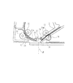
図22に示す従来の原稿読取装置は、プラテンガラス101上に段差形成部材102aを配設すると共に、これらプラテンガラス101及び段差形成部材102aと対向させて且つ離間させて平板形状のプレート103を配設した構成を有する。尚、図22中のQは原稿を示し、Rは原稿による反射光の反射方向(すなわち読み取り位置)を示す。
In the conventional document reading apparatus shown in FIG. 22, a
また、平板形状のプレート103は、プラテンガラス101に対向して配置されて原稿Qを透過した照射光を反射することができるものであればよく、例えば、上記プラテンガラス101に対向して配置された白色ローラでもよい(特許文献1参照)。
The
また、図23に示すように、従来の画像読取装置には、プラテンローラ114及びプラテンガラス111とがなす最狭部分、すなわち読み取り位置となる部分に対し、主走査方向(原稿搬送方向と交差する方向)に1〜3mm幅のスリット穴111aを形成しているものがある。
Further, as shown in FIG. 23, in the conventional image reading apparatus, the narrowest portion formed by the
また、スリット穴111aの下流側の上部の角は、原稿Qの搬送性を良くするため面取りされている(C面)。すなわち、原稿Qの先端の一部がやや落ち込んで搬送されてもすくい上げられるようになっている。さらに、図23における、A,B,C面については表面を磨いて透明にしてある。これによりランプ113の照明光が透過し読取部分に十分な光量を供給することができる(特許文献2参照)。
しかしながら、従来の流し読み用プラテンガラス上の所定の読み取り位置に原稿を接触させずに搬送する手段を有した原稿処理装置には以下のような問題点があった。 However, the conventional document processing apparatus having means for transporting the document without contacting it at a predetermined reading position on the platen glass for flow reading has the following problems.
まず、図22に示すように、プラテンガラス101に段差形成部材102aを設ける方法では、読み取り位置上での原稿Qのばたつきを完全に防止することができないため、特にカラーCCDを用いた画像読取装置のように読取精度を求められる装置では、搬送のばらつきによる画像劣化が懸念される。
First, as shown in FIG. 22, in the method of providing the
また、プラテンガラス101と原稿Qとの隙間を大きく設定できないため、半乾きの修正液やボールペンのインクが大量に原稿に付着していると、プラテンガラス101面に接触してプラテンガラス101を汚してしまい、スジ画像として読み取られてしまう。
In addition, since the gap between the
また、図23に示すように、プラテンガラス111にスリット穴111aを形成する方法では、常に読取装置に穴が空いている状態なので、ユーザーが誤まって原稿Qにステイプル針やクリップ等がついた状態で搬送すると、読取装置内へステイプル針やクリップ等の異物が落下してしまうことが懸念される。
Further, as shown in FIG. 23, in the method of forming the
また、折れ紙やカール紙などの特殊形状用紙に対する搬送性も低下し、万一スリット穴111aに引っかかった場合は、読取装置内部に原稿Qが入り込んでしまい、ユーザーが原稿Qを取り除くことは非常に困難である。
Also, the transportability for specially shaped paper such as folded paper and curled paper is reduced, and if it should be caught in the
そこで本発明は、画像を高い精度で読み取ることができ、且つ操作性及びメンテナンス性の優れた画像読取装置及び画像形成装置を提供することを目的とする。 SUMMARY An advantage of some aspects of the invention is that it provides an image reading apparatus and an image forming apparatus that can read an image with high accuracy and have excellent operability and maintenance.
本発明は上記事項に鑑みてなされたものであり、すなわち本発明は、
原稿上の画像を読み取る読取部と、
前記読取部の上面に配置されたプラテンガラスと、
前記読取部により前記プラテンガラスを介して画像の読み取りを行う読み取り位置へ原稿を搬送する搬送ローラ対と、
前記搬送ローラ対により搬送された前記原稿を前記読み取り位置までガイドする第1ガイド部と、
前記第1ガイド部の原稿搬送方向下流に設けられ、前記読み取り位置を前記プラテンガラスと非接触で通過した前記原稿の先端を受取る第2ガイド部と、
前記第1ガイド部の下流端と前記第2ガイド部の上流端とにより前記読み取り位置に対向して前記プラテンガラスの上方に形成されたスリット部と、
前記第1ガイド部に対向するように前記第1ガイド部の上面側に設けられ、前記第1ガイド部とともに原稿搬送路を構成する第3ガイド部と、
前記第2ガイド部に対向するように前記第2ガイド部の上面側に設けられ、前記第2ガイド部とともに原稿搬送路を構成する第4ガイド部と、
前記第1ガイド部及び前記第2ガイド部の上面側で且つ前記スリット部に対向して回転可能に設けられたプラテンローラであって、前記第1ガイド部と前記プラテンローラとの間隔が、前記第1ガイド部と前記第3ガイド部との間隔よりも狭く、かつ、前記第2ガイド部と前記プラテンローラとの間隔が、前記第2ガイド部と前記第4ガイド部との間隔よ
りも狭くなるように設けられ、前記第1ガイド部及び前記第2ガイド部に前記原稿を押し付けて、回転しながら前記原稿を搬送するように構成されたプラテンローラと、
を備えたことを特徴とする画像読取装置である。
The present invention has been made in view of the above matters, that is, the present invention
A reading unit for reading an image on a document;
A platen glass disposed on the upper surface of the reading unit;
A pair of conveying rollers for conveying the document to a reading position for reading an image through the platen glass by the reading unit;
A first guide portion for guiding the document conveyed by the conveyance roller pair to the reading position;
A second guide part that is provided downstream of the first guide part in the document conveyance direction and receives the leading edge of the document that has passed through the reading position without contact with the platen glass;
A slit portion formed above the platen glass so as to face the reading position by the downstream end of the first guide portion and the upstream end of the second guide portion ;
A third guide part that is provided on the upper surface side of the first guide part so as to face the first guide part and constitutes a document transport path together with the first guide part;
A fourth guide part provided on the upper surface side of the second guide part so as to face the second guide part, and constituting a document transport path together with the second guide part;
A platen roller rotatably provided on the upper surface side of the first guide part and the second guide part and facing the slit part, wherein the distance between the first guide part and the platen roller is The distance between the first guide part and the third guide part is narrower, and the distance between the second guide part and the platen roller is equal to the distance between the second guide part and the fourth guide part.
A platen roller provided to be narrower and configured to convey the document while rotating by pressing the document against the first guide unit and the second guide unit;
An image reading apparatus comprising:
本発明の画像読取装置及び画像形成装置によれば、簡単な構成で読み取り位置にスリットを形成し、原稿を浮かして搬送することができるので、ゴミの影響を受けることなく、高い精度で画像を読み取ることができる画像読取装置及び画像形成装置を低コストで提供することが可能となる。 According to the image reading apparatus and the image forming apparatus of the present invention, it is possible to form a slit at a reading position with a simple configuration and to convey a document while floating, so that an image can be obtained with high accuracy without being affected by dust. An image reading apparatus and an image forming apparatus that can be read can be provided at low cost.
<第1の実施の形態>
以下、本実施形態の画像読取装置及び画像形成装置について図面を参照し説明する。
図1に本実施形態の画像読取装置180を備えた画像形成装置300の一部断面図を示す。
そこで、まず初めに画像形成装置300について説明する。尚、本実施形態における画像形成装置300は、周知の静電潜像画像形成を用いた画像形成部を備えている。
<First Embodiment>
Hereinafter, an image reading apparatus and an image forming apparatus of the present embodiment will be described with reference to the drawings.
FIG. 1 is a partial cross-sectional view of an
First, the
〔画像形成装置〕
図1に示すように、画像形成装置300は、シートを格納する上段カセット200と、この上段カセット200内のシートを分離する上段分離爪(不図示)と、上段給送ローラ201と、上段カセット200の下方に設けられシートを格納する下段カセット202と、この下段カセット202内のシートを分離する下段分離爪(不図示)と、下段給送ローラ203と、上下段それぞれのカセットから分離されたシートを導くレジストローラ206とを有している。
[Image forming apparatus]
As shown in FIG. 1, the
また、画像形成装置300は、画像形成部を形成する構成要素として、例えば感光ドラム212と、現像器214と、転写帯電器215と、分離帯電器216とを有している。
The
このような構成により、画像形成装置300は、画像読み取り開始信号が入力されると、像担持体としての感光ドラム212が帯電器211により所定の電位になるように帯電される。尚、この画像読み取り信号は、画像読取装置180により画像の読み取りが行われることにより生成される。画像読み取り信号を受けた画像形成装置300は、LEDやレ
ーザ等の露光手段213により感光体ドラム212上に、原稿の画像に対応した静電潜像を形成する。この静電潜像は、トナー粒子を収容した現像器214によって現像され、感光体ドラム212上にトナー像が形成される。
With this configuration, when an image reading start signal is input, the
さらに、画像形成装置300には、画像形成されたシートを搬送する搬送ベルト217と、定着装置218と、搬送ローラ219と、フラッパ220と、画像形成されたシートを排出する排出ローラ221と、排出ローラ221から排出されたシートを受け入れるソータ222とが設けられている。このソータ222は、ノンソートトレイ222aと、ソートビントレイ222bと、ノンソートトレイ排出ローラ222cと、ソートビントレイ排出ローラ222dとを有し、ノンソートトレイ222aとソートビントレイ222bとが昇降してシートを一段ずつ区分けする。尚、ソータ222に代わって、排出トレイを装着する場合もある。
Further, the
このような構成により、感光体ドラム212上に形成されたトナー像は、転写帯電器215によって紙やOHP等のシート(記録媒体)上に静電転写される。そして、シートは分
離帯電器216により静電分離され、搬送ベルト217により定着装置218へ搬送される。定着装置218へ搬送されたシートは、定着装置218で熱定着されて画像が出力される。
With such a configuration, the toner image formed on the
〔画像読取装置〕
次に、図1に示す画像読取装置180について説明する。
本実施形態における画像読取装置180は、画像を読み取るリーダ部(読取部)150と、リーダ部150の上部に載置され所定の読み取り位置まで原稿を搬送する自動原稿給送装置(以下、ADFと称す)2とを備えている。
[Image reading device]
Next, the
The
まず初めに、リーダ部150について説明する。
図2に示すように、リーダ部150は、原稿面に対して光を照射するランプ152と、ランプ152にて照射された光に対応する原稿からの反射光をレンズ157及びCCD158に導くミラー153,155,156とを有している。
First, the
As shown in FIG. 2, the
これらのランプ152とミラー153を収納する台を光学台159と称す。光学台159は、図示しないワイヤによって、図3に示すモータ314と結合され、モータ314の回転駆動によりリーダ部150に設けられた原稿台プラテンガラス3と平行に移動制御される。
A table that houses these
また原稿からの反射光は、ミラー153,155,156を介してレンズ157に導か
れ、レンズ157によってCCD158上に集光される。そして、CCD158は、原稿情報を反映した上記反射光を光電変換し電子的な画像信号として出力する。
Reflected light from the original is guided to the
このような構成下で、光学台159を読み取り位置βに停止させた状態で、原稿自動搬送装置2により原稿を搬送させながら原稿の情報を読み取る流し読みモードと、原稿を原稿台プラテンガラス3上に固定的に載置して、光学台159を副走査方向に移動させながら原稿の情報を読み取る固定読みモードの2つのモードで原稿情報を読み取ることができる。
Under such a configuration, in a state where the optical table 159 is stopped at the reading position β, a flow reading mode for reading the document information while the document is conveyed by the
また、リーダ部150は、図3に示すように、各種の装置によって制御されている。リーダ部150の制御部は、原稿面に光を照射するランプ152,光学台159を副走査方向に移動し原稿を走査するモータ314と、原稿面からの反射光を光電変換するCCD158と、CCD158の出力信号をA/D変換するA/D変換回路301と、モータ314に接続されたエンコーダ302と、原稿に光を照射するためのランプ152と、光学台159をホームポジションに位置決めするためのポジションセンサ315と、ADF原稿読取モードにおける正規の原稿読み取り位置を設定するためのバックアップROM304と、スキャナコントローラ305とを有している。
The
また、モータ314は、ステッピングモータにより構成されている。このモータ314には、エンコーダ302(図3参照)が接続されており、このエンコーダ302の出力により、光学台159が何パルス分移動したかを認識できるようになっている。すなわち、ポジションセンサ315とエンコーダ302からのエンコーダーパルスにより、光学台159の位置を把握することが可能である。
The
〔ADFの説明〕
次に、ADF2について説明する。
図1に示すように本実施形態におけるADF2は、リーダ部150の上部に載置されている。より詳細には、ADF2は、リーダ部150にヒンジ機構95,96を介して原稿を載せるための原稿台プラテンガラス3に対して開閉可能に設けられている。
[Description of ADF]
Next, ADF2 will be described.
As shown in FIG. 1, the
また、図2に示すように、ADF2は、原稿Qを積載する原稿トレイ4を有する。原稿トレイ4には一対の幅方向規制板が原稿Qの幅方向にスライド自在に配置されている。幅方向規制板によって原稿トレイ4に積載される原稿Qの幅方向を規制することで給送時の搬送安定性を確保することができる。
As shown in FIG. 2, the
また、原稿トレイ4の上方には、給送ローラ5が設けられている。給送ローラ5は分離搬送ローラ8の回転駆動に連れて回転し原稿Qを給送する。給送ローラ5は通常、ホームポジションである上方(図2中点線位置)に待避している位置をとり、原稿セット作業を阻害しないようにしている。給送動作が開始されると下降して原稿Qの上面に当接する(図2中実線位置)。給送ローラ5は図示しないアームにて軸支されるので、アームを揺動して給送ローラ5を上下に動かせる。
A feeding
また、ADF2には、分離搬送ローラ8の対向側に配置され分離搬送ローラ8側に圧力を加えている分離パッド6が設けられている。分離パッド6は分離搬送ローラ8より摩擦が若干小さいゴム材料などで形成され、給送ローラ5にて給送される原稿Qを一枚毎にさばき、分離搬送ローラ8で原稿Qを給送する。
The
さらに、ADF2には、分離部にて給送された原稿Qの先端をそろえるレジスト手段が設けられている。レジスト手段は、レジスト従動ローラ11とレジストローラ12とが対(以下、レジストローラ対と称す)の構成を成しており、静止したレジストローラ対11
,12がニップ部に向けて分離した原稿Qの先端を突き当て、さらに搬送することによって原稿Qにループを生じさせて先端をそろえる。
Further, the
, 12 abuts the leading edge of the original Q separated toward the nip portion, and further conveys it to cause a loop in the original Q to align the leading edges.
図4に示すように、本実施形態のADF2には、レジストローラ対11,12を通過した原稿を読み取り位置βまでガイドする上流搬送ガイド(第1ガイド部)25が設けられている。上流搬送ガイド25は、原稿Qを読み取り位置βまで搬送するリードローラ22とリード従動ローラ14から読み取り位置βに向かって湾曲に形成されている。また、この上流搬送ガイド25と向かい合って、すなわち上流搬送ガイド25の上側に上ガイド25a(第3ガイド部)が設けられている。この上ガイド25aも上流搬送ガイド25と同じようにリードローラ22とリード従動ローラ14から湾曲に形成されている。尚、上ガイド25aには、上流搬送ガイド25上を搬送されてきた原稿Qの動きを上面側から規制する役割がある。
As shown in FIG. 4, the
また、原稿Qの搬送方向にシートをガイドする部材として、例えば白色のプラテンローラ24を有している。このプラテンローラ24は、リーダ部150の光学台159が画像の読み取りを行う読み取り位置βに対応する位置に設けられ、読み取り位置βに搬送されてきた原稿Qの動きを上面側から規制する役割がある。
Further, as a member for guiding the sheet in the conveyance direction of the document Q, for example, a
さらに、上流搬送ガイド25の原稿搬送方向下流には、原稿Qの搬送をガイドする下流搬送ガイド(第2ガイド部)26が設けられている。この下流搬送ガイド26は読み取り位置βから、原稿搬送方向下流に設けられた、搬出ローラ対を形成するリード排出ローラ23とリード排出従動ローラ16に向かって延びている。下流搬送ガイド26は、上流搬送ガイド25を通過した原稿Qの先端を受け取り易くするために、上流搬送ガイド25の終端より低い位置に下流搬送ガイド26の基端が位置している。さらに、下流搬送ガイド26の基端は原稿台プラテンガラス3の上面と間隙をもって配置されているので、上流搬送ガイド25を通過した原稿Qの先端は原稿台プラテンガラス3に接触することがなく、この構成により、原稿Qは原稿台プラテンガラス3から浮いた状態で読み取り位置β上を搬送され、原稿台プラテンガラス3上のゴミの影響を受けることが少ない。尚、下流搬送ガイド26に対向する位置、すなわち下流搬送ガイド26の上側には上ガイド26a(第4ガイド部)が設けられている。この上ガイド26aには搬送されてきた原稿Qの揺れを上面側から規制する役割がある。
Further, a downstream conveyance guide (second guide portion) 26 for guiding the conveyance of the document Q is provided downstream of the
また、本実施形態に係るADF2は、上流搬送ガイド25と下流搬送ガイド26との間に所定幅のスリット部27を有する。つまり、上流搬送ガイド25と下流搬送ガイド26との向かい合う端部間に設けられた隙間がスリット部27となる。このスリット部27は主走査方向、すなわち原稿Qの搬送方向と交差する方向に延びている。そして、光学台159はこのスリット部27の下方に固定され、原稿Qの画像読み取りを行う。つまり図4に示されるように、スリット部27の位置と読み取り位置βとプラテンローラ24の中心位置は同一線上に合致することになる。
Further, the
また、リード排出ローラ23とリード排出従動ローラ16との原稿搬送方向下流には、図2に示すように排出ローラ18が設けられており、排出ローラ18を通過した原稿Qは排出トレイ10に排出される。尚、上述したADF2はマイクロプロセッサ(CPU)54を中心に構成された制御回路にて駆動が制御されている。
Further, as shown in FIG. 2, a
次に、本実施形態に係るADF2に設けられた各ローラ等を駆動する駆動系やセンサについて説明する。
Next, a drive system and sensors for driving each roller and the like provided in the
〔駆動系の説明〕
図5に本実施形態に係るADF2の制御ブロック図を示し、図6に本実施形態に係るADF2が有するモータ及びセンサ類の接続状態図を示す。
[Description of drive system]
FIG. 5 shows a control block diagram of the
図5に示すように、本実施形態に係るADF2の制御回路は主にマイクロプロセッサ(以下、CPUと称す)54が中心となり各種センサやモータが制御されている。
As shown in FIG. 5, the control circuit of the
また、分離モータ50はステッピングモータであり、正逆転により原稿の分離・搬送を行なう。分離モータ50が給送方向に回転したときには、図2に示すように、給送ローラ5がホームポジションである上方(図2中破線位置)から降下し、原稿トレイ4上の原稿Qに圧接させると共に、給送ローラ5と分離搬送ローラ8を駆動する。
The
分離モータ50が給送方向とは逆転方向である搬送方向に回転したときには、原稿Qに圧接した状態(図2中実線位置)から給送ローラ5をホーム位置である上方(図2中破線位置)に持上げ保持すると共に、レジストローラ12を駆動する。
When the
リードモータ51は、リードローラ22,リード排出ローラ23,排出ローラ18を駆動するステッピングモータである。リードモータ51は、搬送される原稿Qの画像を読み取る速度で各ローラを駆動させる。
The read
また、離間ソレノイド57は両面原稿スイッチバック時に、排出ローラ18の従動コロを圧着・離間させる。
The
〔センサの説明〕
次に、各センサの説明をする。
[Explanation of sensor]
Next, each sensor will be described.
図6に示すように、原稿トレイ4には原稿がセットされたことを検出する透過型の光センサである原稿セット検知センサ40が設けられている。また、サイドガイドの位置を検出する事により原稿トレイ4上にセットされた原稿束の幅方向の長さを検知する紙幅検知センサ44が原稿トレイ4の下部に設けられている。
As shown in FIG. 6, the
分離搬送ローラ8とレジストローラ12の間には原稿を検知する透過型の光センサであるレジストセンサ7が設けられ、分離給送された原稿の先端を検知し、レジストローラ12への突き当て量(ループ量)を制御するタイミングなどを検知している。
A
リードローラ22の直後に原稿を検知する反射型光センサであるリードセンサ(原稿検知手段)13が設けられ、読み取り位置βでの画像読み取り開始タイミングの基準信号としている。
A read sensor (original detection means) 13 which is a reflection type optical sensor for detecting an original is provided immediately after the read
排出ローラ18の直前には原稿を検知する透過型光センサである排出センサ17が設けられ、原稿の排出タイミングなどを検知している。
A
〔読み取り機構の動作説明〕
次に、本実施形態の画像読取装置180によって原稿Qの画像を読み取る機構について説明する。
[Description of reading mechanism operation]
Next, a mechanism for reading an image of the original Q by the
まず、図2に示すように、ADF2の原稿トレイ4上に原稿Qをセットする。このとき原稿Qの先端は給送ローラ5に当接している。そのため、原稿Qの読み取りが開始されると、給送ローラ5は分離搬送ローラ8の回転駆動に連れて回転し、原稿Qを分離パッド6に給送する。分離搬送ローラ8と分離パッド6とにより一枚毎に分離された原稿Qは、レジストローラ対11,12を通過し、図4に示すように、上流搬送ガイド25にガイドされリードローラ22とリード従動ローラ14とを通過する。
First, as shown in FIG. 2, the document Q is set on the
原稿Qはさらに上流搬送ガイド25にガイドされて駆動源となるリードモータ(不図示)の駆動により搬送方向に回転するプラテンローラ24へと搬送される。このプラテンローラ24が読み取り時に原稿Qの上下動を抑えるため原稿Qの搬送が安定する。画像の読み取りは、光学台159を読み取り位置βに移動させて行われる。
The document Q is further guided to the
このとき、光学台159が固定読みモード時に読み取りを行う光路長と、流し読みモード時に読み取りを行う光路長とが異なるため、光学台159の光路長は、原稿台プラテンガラス3に原稿を載置させ画像を読み取る固定読みモードでも、原稿トレイ4から読み取り位置βまで原稿Qを搬送させて画像を読み取る流し読みモードでも読み取りが可能な深度に設定されている。
At this time, since the optical path length that the
また、原稿Qはリードローラ22により上流搬送ガイド25に沿って搬送され、スリット部27で画像を読み取られ、下流搬送ガイド26に受け渡されてリード排出ローラ23に巻き取られ排出ローラ18を介して排出トレイ10に搬送される。このとき、原稿Qは原稿台プラテンガラス3から浮いた状態でスリット部27を通過する。
Further, the document Q is conveyed along the
以上が、本実施形態の画像読取装置180が原稿トレイ4から搬送された原稿Qの画像を読み取るプロセスである。
The above is the process of reading the image of the original Q conveyed from the
このように、本実施形態の画像読取装置180によれば、原稿Qが原稿台プラテンガラス3と非接触で搬送されるため、糊,修正液,インク等の汚れ・ゴミが原稿台プラテンガラス3に付着するのを防ぐことができる。これによって、高い精度で画像の読み取りを行うことが可能となる。
As described above, according to the
さらに、本実施形態における画像読取装置180の原稿台プラテンガラス3は、ガラスにスリット穴が設けられていないため、リーダ部150(画像読取装置180)内にステイプル針やクリップ等の異物の混入を防ぐことができる。
Further, since the
また、上流搬送ガイド25の終端は下流搬送ガイド26の基端よりも上方にあるため、スリット部27を挟んだガイド間の原稿の受渡しがスムーズに行うことができる。これによって高精度の画像を得ることができる。
Further, since the end of the
さらに、本実施形態の画像読取装置180は、原稿Qを上流搬送ガイド25および下流搬送ガイド26に押し付けて搬送し、且つ回転するプラテンローラ24によりパス間隔を狭く拘束されている。そのため、プラテンローラ24から突脱したショックによる速度変動のばらつきを軽減できる。
Further, the
また、図4に示すように、上流搬送ガイド25と下流搬送ガイド26との間にスリット部27を形成することにより、リーダ部150に従来のような段差形成部材2a(図22参照)を設ける必要がなくなり、1枚板の原稿台プラテンガラス3をそのまま利用して読み取りを行うことができる。そのため、従来のように原稿台ガラスとしてのプラテンガラスとそれとは別の流し読み専用のプラテンガラスとの2枚ガラスを用いた構成にする必要がなくなり、低コスト且つ省スペースを実現することができる。
Further, as shown in FIG. 4, a
また、本実施形態の画像読取装置180によれば、読み取り位置直前まで上流搬送ガイド25が延びているために、原稿Qが上流搬送ガイド25から突脱したときのショックの発生もなく、画像の伸び縮みの発生を防止し、高精度の流し読み画像を得ることができる。
Further, according to the
<第2の実施の形態>
以下に、第2の実施の形態の画像読取装置について説明する。尚、以下の説明では、第1の実施の形態と同一の構成についての説明は省略し、第1の実施の形態と異なる構成についてのみ説明する。
<Second Embodiment>
The image reading apparatus according to the second embodiment will be described below. In the following description, the description of the same configuration as that of the first embodiment is omitted, and only the configuration different from that of the first embodiment will be described.
まず、本実施形態に係るADF2に設けられた各ローラ等を駆動する駆動系やセンサについて説明する。
〔駆動系の説明〕
図7に本実施形態に係るADF2が有するモータ及びセンサ類の接続状態図を示し、図8に本実施形態に係るADF2が有するモータ及びセンサ類の接続状態図を示す。本実施形態に係るADF2は、上述した第1の実施の形態の制御回路とほぼ同じ構成であり、制御手段として、例えばCPU54が中心となって各種センサやモータが制御されている。その他にも第1の実施の形態同様に、本実施形態の制御回路は、分離モータ50,リードモータ51,離間ソレノイド57がCPU54に接続されている。
First, a drive system and sensors that drive each roller and the like provided in the
[Description of drive system]
FIG. 7 is a connection state diagram of motors and sensors included in the
本実施形態のADF2は、さらに揺動モータ(駆動手段)58を有している。揺動モータ58は、読み取り動作時に下流搬送ガイド26をリード排出従動ローラ16の軸を揺動中心として規制コロ29との当接位置と離間位置に揺動させるステッピングモータである(図9参照)。また、本実施形態ではステッピングモータを例に挙げているが、DCモータ等の他のモータやソレノイド,クラッチ等の揺動機能を満足する駆動手段であればいずれのものにも限定しない。揺動モータ58も制御手段としてのCPU54によって制御される。
The
〔センサの説明〕
次に、各センサの説明をする。本実施形態に係るADF2も、上述した第1の実施の形態のADFと同様に、原稿セット検知センサ40,紙幅検知センサ44,レジストセンサ7,リードセンサ13を有している。
[Explanation of sensor]
Next, each sensor will be described. The
さらに、本実施形態に係るADF2は、原稿が読み取り位置を通過したか否かを検知する、読み取り位置検知手段としての読み取り位置検知センサ60がスリット部27に設けられている。尚、本実施形態に係る読み取り位置検知センサ60は、上流搬送ガイド25の終端に設けられているが下流搬送ガイド26の基端に設けられていてもよいし、読み取り位置βを通過したことを検知する位置であればこれに限るものではない。
Furthermore, the
〔ADFの説明〕
本実施形態に係るADF2は、第1の実施の形態に係るADF2と同じくリードローラ22と、リード従動ローラ14とを有している。尚、これらのローラは対(搬送ローラ対)を成している。図9に示すように、リードローラ22とリード従動ローラ14の搬送方向下流には、上流搬送ガイド(第1ガイド部)25が設けられている。上流搬送ガイド25は、原稿Qを読み取り位置βまで搬送するリードローラ22とリード従動ローラ14から読み取り位置βに向かって湾曲に形成されている。また、この上流搬送ガイド25と向かい合って、すなわち上流搬送ガイド25の上側に上ガイド25aが設けられている。この上ガイド25aも上流搬送ガイド25と同じようにリードローラ22とリード従動ローラ14から湾曲に形成されている。尚、上ガイド25aには、上流搬送ガイド25上を搬送されてきた原稿Qの動きを上面側から規制する役割がある。
[Description of ADF]
Similar to the
加えて、この上流搬送ガイド25上には、上流搬送ガイド25上面から原稿Qの厚さより大きな隙間を空けた位置に規制コロ(規制手段)28が設けられている。原稿Qは、リードローラ22とリード従動ローラ14とにより上流搬送ガイド25及び規制コロ28に沿って搬送されていく。
In addition, a regulation roller (regulation means) 28 is provided on the
また、上流搬送ガイド25の原稿搬送方向下流には、上流搬送ガイド25から搬送された原稿Qを受け取る下流搬送ガイド(第2ガイド部)26が設けられている。この下流搬送ガイド26は読み取り位置βから、原稿搬送方向下流に設けられた、搬出ローラ対を形成するリード排出ローラ23とリード排出従動ローラ16に向かって延びている。下流搬送ガイド26は、上流搬送ガイド25を通過した原稿Qの先端をすくい取るために、上流搬送ガイド25の終端よりも低い位置からガイドを形成している。下流搬送ガイド26の基端は、原稿台プラテンガラス3の上面と間隔をおいて配置されている(図9中点線位置)。尚、下流搬送ガイド26に対向する位置、すなわち下流搬送ガイド26の上側には上ガイド26aが設けられている。この上ガイド26aは搬送されてきた原稿Qの揺れを上面側から規制する。
A downstream conveyance guide (second guide portion) 26 that receives the document Q conveyed from the
また、本実施形態に係るADF2は、上流搬送ガイド25と下流搬送ガイド26の間に所定幅のスリット部27を有する。つまり、上流搬送ガイド25と下流搬送ガイド26との向かい合う端部間に設けられた隙間がスリット部27となる。このスリット部27は主走査方向、すなわち原稿搬送方向と交差する方向に延びている。そして、光学台159はこのスリット部27の下方に固定され、原稿Qの画像読み取りを行う。つまり図9に示すように、スリット部27の位置と読み取り位置βとシートガイド部材としてのプラテンガイド30の位置は同一線上に合致することになる。
Further, the
さらに、下流搬送ガイド26上にもその上面から原稿の厚さより大きな隙間を空けた位置に規制コロ(規制手段)29が設けられている。
Further, a regulation roller (regulation means) 29 is provided on the
また、搬出手段としてのリード排出ローラ23とリード排出従動ローラ16の原稿搬送方向下流には、第1の実施の形態と同じく排出ローラ(不図示)が設けられており、排出ローラを通過した原稿は排出トレイ(不図示)に排出される。
Similarly to the first embodiment, a discharge roller (not shown) is provided downstream of the
また、下流搬送ガイド26は、リード排出従動ローラ16の軸を揺動中心として図9中点線位置と実線位置に揺動可能に設けられている。この下流搬送ガイド26の揺動範囲は、下流搬送ガイド26の基端が上流搬送ガイド25の先端よりも原稿台プラテンガラス3側に下がった待機位置から、規制コロ29に当接して原稿を挟持する搬送位置までである。
Further, the
〔読み取り機構の動作説明〕
次に、本実施形態の画像読取装置180によって原稿Qの画像を読み取る機構について説明する。尚、本実施形態における原稿の搬送行程は、原稿がリードローラ,リード従動ローラに到達するまでは第1の実施の形態と同じであるため、その説明を省略する。
図10に示すように、各ローラを通過した原稿Qは、上流搬送ガイド25にガイドされリードローラ22とリード従動ローラ14とを通過する。
[Description of reading mechanism operation]
Next, a mechanism for reading an image of the original Q by the
As shown in FIG. 10, the document Q that has passed through each roller is guided by the
すると、原稿Qは上流搬送ガイド25にガイドされる。このとき原稿Qの先端が、原稿検知手段としてのリードセンサ13に達すると、リードセンサ13が原稿Qを検知する。このとき下流搬送ガイド26は待機位置に保持されている。
Then, the document Q is guided by the
そして、図11に示すように、原稿Qの先端がリード排出ローラ23とリード排出従動コロのニップに挟持されると、下流搬送ガイド26は揺動モータ58の駆動により規制コロ29側(図11中矢印L方向)に移動される。このとき、リードセンサ13が原稿Qの先端を検知し始めてからの時間をカウントし、原稿Qの先端がニップを通過する時間が経過した後に、揺動モータ58を駆動する制御を行っている。尚、リード排出ローラ23とリード排出従動ローラ16のニップを通過する距離は約5mmに設定されている。
Then, as shown in FIG. 11, when the leading edge of the document Q is sandwiched between the nip between the
また、図12に示すように、原稿Qはリードローラ22とリード排出ローラ23に挟持されて搬送されていく。このとき、下流搬送ガイド26は、規制コロ29側に移動しており、下流搬送ガイド26と規制コロ29とが原稿Qを挟持した状態をなしている。これにより、搬送中の原稿Qのばたつきを防止して安定した搬送を行うことができる。
Further, as shown in FIG. 12, the document Q is nipped between the
また、図13に示すように、原稿Qの後端がリードセンサ13に達したときに、リードセンサ13が原稿Qの後端を検知する。このときはまだ、下流搬送ガイド26は規制コロ29側に位置しており原稿Qの搬送動作を行っている。
Further, as shown in FIG. 13, when the trailing edge of the document Q reaches the
また、図14に示すように、原稿Qの後端が読み取り位置βを通過すると読み取り位置検知センサ60が原稿Qの通過を検知する。この検知結果を受けて揺動モータ58が駆動する。すると、揺動モータ58の駆動力により、下流搬送ガイド26が規制コロ29から離間させる方向(図14中矢印M方向)に移動される。このとき、リードセンサ13が原稿Qの後端を検知し始めてからの時間をカウントし、原稿Qの後端が読み取り位置βを通過する時間が経過した後に、揺動モータ58を駆動する。
As shown in FIG. 14, when the trailing edge of the document Q passes the reading position β, the reading
そして、原稿Qは、図15に示すように、リード排出ローラ23により排出トレイ10へと搬送される。このとき、下流搬送ガイド26は、規制コロ29とは離間する位置に移動しており、次の原稿を受けるための待機状態となる。
Then, the document Q is conveyed to the
以上が本実施形態における画像読取装置180の読み取り機構である。
The above is the reading mechanism of the
上述したように、本実施形態における画像読取装置180は、原稿Qの先端突入時に下流搬送ガイド26が規制コロ29と離間した位置にあるので、原稿Qの先端の受け渡し性、特に折れ紙やカール紙等の特殊形状をなす原稿に対して、上流搬送ガイド25からの原稿Qの受け渡し性を向上させることができる。それに伴い、上流搬送ガイド25と下流搬送ガイド26との間に形成されたスリット部27のスリット幅を広く設定しても搬送性を十分に確保できるようになり、上流搬送ガイド25及び下流搬送ガイド26の影による読取光量が低下するのを防止することができる。
As described above, in the
さらに、本実施形態における画像読取装置180は、原稿Qの搬送中は、下流搬送ガイド26と規制コロ29とにより原稿Qを挟持するため、搬送による振動やショックによる画像の劣化を防止することができる。それと共に、本実施形態における画像読取装置180の規制コロ29は、原稿Qの後端まで原稿Qを挟持するため原稿Qが規制コロ29を抜けたときのショックも軽減できる。
Furthermore, the
また、本実施形態における画像読取装置180は、原稿Qが原稿台プラテンガラス3の上面とは非接触で搬送されるため、糊,修正液,インク等のゴミが読み取り位置上に付着することがなく、スジ画像の発生を防止することができる。
In the
さらに、本実施形態における画像読取装置180の原稿台プラテンガラス3は、ガラスにスリット穴が設けられていないため、リーダ部150(画像読取装置180)内にステイプル針やクリップ等の異物の混入を防ぐことができる。
Further, since the
以下に、本発明の画像読取装置のそのほかの実施の形態について説明する。尚、以下の説明では、第1の実施の形態及び第2の実施の形態と同一の構成についての説明は省略し、それらとは異なる構成についてのみ説明する。 Other embodiments of the image reading apparatus of the present invention will be described below. In the following description, descriptions of the same configurations as those in the first embodiment and the second embodiment are omitted, and only configurations different from those will be described.
<第3の実施の形態>
図16に示すように、本実施形態のADF2は、上述した第1の実施の形態に係るAD
F2に設けられたプラテンローラ24と、第2の実施の形態に係るADF2に設けられた、下流搬送ガイド26を駆動させる揺動モータ58(図7参照)とを有している。
<Third Embodiment>
As shown in FIG. 16, the
It has the
本実施形態の画像読取装置180は、ADF2のプラテンローラ24によって原稿Qを上流搬送ガイド25及び下流搬送ガイド26に押し付けて搬送することができる。そのため、原稿Qがプラテンローラ24から突脱したショックによる速度の変動を少なくすることができる。
The
あわせて、本実施形態の画像読取装置180は、ADF2の下流搬送ガイド26が原稿Qの先端突入時にプラテンローラ24から離れる方向に揺動し、下流搬送ガイド26の基端が上流搬送ガイド25の終端よりも下方になるので、上流搬送ガイド25からの原稿Qの受け渡し性を向上させることができる。そのため、下流搬送ガイド26は、スリット部27を通過してきた原稿Qを衝撃が少なく且つスムーズにすくい取ることができる。
In addition, in the
<第4の実施の形態>
図17に示すように、本実施形態のADF2には、シートガイド部材としてのプラテンローラ24の上流ないしは下流に上流搬送ガイド25と下流搬送ガイド26とに微小なギャップを形成して原稿Qを拘束する、規制手段としての規制コロ28,29が設けられている。
<Fourth embodiment>
As shown in FIG. 17, in the
この規制コロ28,29は、上ガイド25a,26aに設けられ、読み取り位置βの前後で各搬送ガイド(上流搬送ガイド25,下流搬送ガイド26)方向に原稿Qを押し付けて原稿Qの挙動を規制する。これによって、原稿Qがリードローラ22及びリード従動ローラ14からの突脱によるショックや、各搬送ガイド(上流搬送ガイド25,下流搬送ガイド26)から抜けたときに生じるショック(揺れ)が緩和され高精度の流し読み画像を得ることが可能となる。
The
また、規制コロ28,29が原稿Qを上流搬送ガイド25,下流搬送ガイド26に押し付けることは、その反作用によりプラテンローラ24が原稿Qを規制コロ28,29に押し付けていることにもなる。これにより、原稿Qはプラテンローラ24と規制コロ28,29によりしっかり挟持されるため、搬送に伴う揺れや衝撃を極力少なくすることができる。尚、この他にも、上流搬送ガイド25又は下流搬送ガイド26の少なくとも一方の上面に、原稿Qを規制コロ28,29に押し付ける単独の部材を設ける構成としてもよい。
Further, when the
また、規制コロ28,29により原稿Qが安定して搬送されるため、原稿Qのパス間隔を拘束することができ、より高精度の流し読み画像を得ることができる。
In addition, since the document Q is stably conveyed by the
加えて、本実施形態に係る上流搬送ガイド25も上述した実施形態と同様に下流搬送ガイド26よりも上方にあるため、スリット部27の搬送パスをスムーズに行うことができる。これによって高精度の画像を得ることができる。
In addition, since the
<第5の実施の形態>
図18に示すように、本実施形態のADF2には、上ガイド25a,26aに設けられ、上流搬送ガイド25及び下流搬送ガイド26に原稿Qを押し付ける弾性力を持った、規制手段としての付勢部材33が設けられている。この付勢部材33は、第3の実施の形態における規制コロ28,29(図17参照)と同等の役割を果たすことができ、安定した搬送を促すことにより高精度の流し読み画像を得ることができる。
<Fifth embodiment>
As shown in FIG. 18, the
また、付勢部材33が読み取り位置βでシートガイド部材としてのプラテンローラ24に原稿Qを押し付ける構成となっていることにより、原稿Qがリードローラ22及びリー
ド従動ローラ14から突脱することによるショック(例えば、原稿Qの位置がずれること)や、原稿Qが各搬送ガイド(上流搬送ガイド25,下流搬送ガイド26)から抜けたときに生じるショックが緩和され高精度の流し読み画像を得ることが可能となる。
Further, since the biasing
さらに、付勢部材33がプラテンローラ24側に原稿Qを押し付けていることにより、原稿Qのパス間隔を拘束することができる。これによって、より高精度の流し読み画像を得ることができる。
Furthermore, since the urging
加えて、本実施形態に係る上流搬送ガイド25も上述した実施形態と同様に下流搬送ガイド26よりも上方にあるため、スリット部27の搬送パスをスムーズに行うことができる。これによって高精度の画像を得ることができる。
In addition, since the
<第6の実施の形態>
図19に示すように、本実施形態のADF2には、上流搬送ガイド25との間に微少なギャップを形成して原稿Qを拘束する規制コロ28と、スリット部27の上方にシートガイド部材としてのプテランガイド30が設けられている。
<Sixth Embodiment>
As shown in FIG. 19, the
これによって、規制コロ28が上流搬送ガイド25側に原稿Qを押し付けると共に読み取り位置βでプテランガイド30が原稿Qの上面を押さえるため、原稿Qの搬送速度の変動を軽減することができ原稿Qを安定させて搬送することができる。これによって高精度の流し読み画像を得ることが可能となる。尚、このときプラテンガイド30と上流搬送ガイド25,下流搬送ガイド26とのパス間隔は、第1、第3実施形態のように回転するプラテンローラを使用するときよりも広く設定されていると好ましい。
As a result, the
加えて、本実施形態に係る上流搬送ガイド25の終端も上述した実施形態と同様に下流搬送ガイド26の基端よりも上方にあるため、スリット部27を挟んだガイド間の原稿の受渡しがスムーズに行うことができる。これによって高精度の画像を得ることができる。
In addition, since the end of the
<第7の実施の形態>
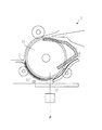
図20に示すように、本実施形態のADF2は、シートガイド部材としての回転する大径のプラテンローラ24と、読み取り位置βの前後に設けられた規制手段としての規制コロ31,32とを有している。このような径の大きなプラテンローラ24は、原稿Qを等速で搬送することができる。これによって、原稿Qは、スリット部27上も安定して搬送されるため、高精度の流し読み画像を得ることができる。
<Seventh embodiment>
As shown in FIG. 20, the
また、規制コロ31,32を読み取り位置β前後に設け、プラテンローラ24に押し付けるような構成にすることで、読み取り位置β前後でしっかりと原稿Qをグリップして速度変動を防止すると共に、読み取り終了直前まで原稿Qを拘束することができるため、原稿Qが上流搬送ガイド25を抜けるときに発生するショックを防止することができる。これらのことにより、画像を高い精度で読み取ることが可能となる。
Further, by providing the
加えて、本実施形態に係る上流搬送ガイド25も上述した実施形態と同様に下流搬送ガイド26よりも上方にあるため、スリット部27を挟んだガイド間の原稿の受渡しがスムーズに行うことができる。これによって高精度の画像を得ることができる。
In addition, since the
<第8の実施の形態>
図21に示すように、本実施形態のADF2には、上流搬送ガイド25上に弾性力を持った、規制手段としての付勢部材33が設けられている。この付勢部材33は、上流搬送ガイド25終端に向かって上へ反っており、反りあがった先端はプラテンローラ24に押し付く構成をなしている。
<Eighth Embodiment>
As shown in FIG. 21, the
このように、付勢部材33がプラテンローラ24に押しつくことにより、第6の実施の形態における規制コロ31,32と同等の効果を得ることができる。尚、本実施形態ではシートガイド部材としてプラテンローラ24を用いて説明しているが、回転体の大径プラテンローラ24の代わりに、原稿Qのμより十分に低いプラテンガイドを使用してもよい。
As described above, when the urging
加えて、本実施形態に係る上流搬送ガイド25の終端も上述した実施形態と同様に下流搬送ガイド26の基端よりも上方にあるため、スリット部27の搬送パスをスムーズに行うことができる。これによって高精度の画像を得ることができる。
In addition, since the end of the
14 リード従動ローラ(搬送ローラ対)
16 リード排出従動ローラ(搬出ローラ対)
22 リードローラ(搬送ローラ対)
23 リード排出ローラ(搬出ローラ対)
24 プラテンローラ(規制手段)
25 上流搬送ガイド(第1ガイド部)
26 下流搬送ガイド(第2ガイド部)
27 スリット部
28 規制コロ(規制手段)
29 規制コロ(規制手段)
180 画像読取装置
150 リーダ部(読取部)
Q 原稿
14 Lead driven roller (conveying roller pair)
16 Lead discharge driven roller (pair of discharge rollers)
22 Lead roller (conveying roller pair)
23 Lead discharge roller (unloading roller pair)
24 Platen roller (regulation means)
25 Upstream transport guide (first guide)
26 Downstream transport guide (second guide)
27
29 Regulation roller (regulation means)
180
Q Manuscript
Claims (7)
前記読取部の上面に配置されたプラテンガラスと、
前記読取部により前記プラテンガラスを介して画像の読み取りを行う読み取り位置へ原稿を搬送する搬送ローラ対と、
前記搬送ローラ対により搬送された前記原稿を前記読み取り位置までガイドする第1ガイド部と、
前記第1ガイド部の原稿搬送方向下流に設けられ、前記読み取り位置を前記プラテンガラスと非接触で通過した前記原稿の先端を受取る第2ガイド部と、
前記第1ガイド部の下流端と前記第2ガイド部の上流端とにより前記読み取り位置に対向して前記プラテンガラスの上方に形成されたスリット部と、
前記第1ガイド部に対向するように前記第1ガイド部の上面側に設けられ、前記第1ガイド部とともに原稿搬送路を構成する第3ガイド部と、
前記第2ガイド部に対向するように前記第2ガイド部の上面側に設けられ、前記第2ガイド部とともに原稿搬送路を構成する第4ガイド部と、
前記第1ガイド部及び前記第2ガイド部の上面側で且つ前記スリット部に対向して回転可能に設けられたプラテンローラであって、前記第1ガイド部と前記プラテンローラとの間隔が、前記第1ガイド部と前記第3ガイド部との間隔よりも狭く、かつ、前記第2ガイド部と前記プラテンローラとの間隔が、前記第2ガイド部と前記第4ガイド部との間隔よりも狭くなるように設けられ、前記第1ガイド部及び前記第2ガイド部に前記原稿を押し付けて、回転しながら前記原稿を搬送するように構成されたプラテンローラと、
を備えたことを特徴とする画像読取装置。 A reading unit for reading an image on a document;
A platen glass disposed on the upper surface of the reading unit;
A pair of conveying rollers for conveying the document to a reading position for reading an image through the platen glass by the reading unit;
A first guide portion for guiding the document conveyed by the conveyance roller pair to the reading position;
A second guide part that is provided downstream of the first guide part in the document conveyance direction and receives the leading edge of the document that has passed through the reading position without contact with the platen glass;
A slit portion formed above the platen glass so as to face the reading position by the downstream end of the first guide portion and the upstream end of the second guide portion;
A third guide portion that is provided on the upper surface side of the first guide portion so as to face the first guide portion and constitutes a document transport path together with the first guide portion;
A fourth guide part provided on the upper surface side of the second guide part so as to face the second guide part, and constituting a document transport path together with the second guide part;
A platen roller rotatably provided on the upper surface side of the first guide part and the second guide part and facing the slit part, wherein the interval between the first guide part and the platen roller is The distance between the first guide part and the third guide part is narrower, and the distance between the second guide part and the platen roller is narrower than the distance between the second guide part and the fourth guide part. A platen roller configured to convey the document while rotating by pressing the document against the first guide unit and the second guide unit;
An image reading apparatus comprising:
稿搬送方向下流端よりも下になる退避位置と、前記退避位置の上方に位置し、原稿を搬送する搬送位置との間を移動させる駆動手段を備えることを特徴とする請求項1又は2に記載の画像読取装置。 The second guide unit is positioned at a retracted position where the upstream end of the second guide unit in the document transport direction is lower than the downstream end of the first guide unit in the document transport direction, and above the retracted position, the image reading apparatus according to claim 1 or 2, characterized in that it comprises a driving means for moving between a transport position for transporting.
前記原稿の先端が前記搬出ローラ対に挟持されると、前記第2ガイド部を前記待機位置から前記搬送位置へ移動させ、
前記原稿の後端が前記読み取り位置を通過すると、前記第2ガイド部を前記搬送位置から前記待機位置へ移動させるよう前記駆動手段を制御する制御手段を備えたことを特徴とする請求項4に記載の画像読取装置。 A pair of unloading rollers disposed downstream of the reading position and configured to unload a document that has passed through the reading position from the second guide portion;
When the leading edge of the document is sandwiched between the pair of carry-out rollers, the second guide portion is moved from the standby position to the transport position,
5. The apparatus according to claim 4 , further comprising a control unit that controls the driving unit to move the second guide unit from the transport position to the standby position when the trailing edge of the document passes the reading position. The image reading apparatus described.
前記制御手段は、
前記原稿検知手段による前記原稿の先端検知信号に基づき、前記原稿の先端が前記搬出ローラ対に挟持されたと判断して前記第2ガイド部を前記待機位置から前記搬送位置へ移動させ、前記原稿検知手段による前記原稿の後端検知に基づき、前記原稿の後端が前記読み取り位置を通過したと判断して前記第2ガイド部を前記搬送位置から前記待機位置へ移動させることを特徴とする請求項5に記載の画像読取装置。 The first guide unit has document detection means for detecting the leading edge and the trailing edge of the document,
The control means includes
Based on the leading edge detection signal of the document by the document detecting means, it is determined that the leading edge of the document is sandwiched between the pair of carry-out rollers, and the second guide unit is moved from the standby position to the transport position, thereby detecting the document. The second guide unit is moved from the conveyance position to the standby position by determining that the trailing edge of the document has passed the reading position based on detection of the trailing edge of the document by means. The image reading apparatus according to 5 .
前記画像読取装置は、請求項1乃至6の何れかに記載の画像読取装置であることを特徴とする画像形成装置。 An image reading apparatus having a reading unit that reads a document passing through a reading position; and an image forming unit that forms an image on a sheet based on image information read by the reading unit;
The image reading apparatus, an image forming apparatus, wherein an image reading apparatus according to any one of claims 1 to 6.
Priority Applications (1)
| Application Number | Priority Date | Filing Date | Title |
|---|---|---|---|
| JP2004147493A JP4447958B2 (en) | 2004-05-18 | 2004-05-18 | Image reading apparatus and image forming apparatus |
Applications Claiming Priority (1)
| Application Number | Priority Date | Filing Date | Title |
|---|---|---|---|
| JP2004147493A JP4447958B2 (en) | 2004-05-18 | 2004-05-18 | Image reading apparatus and image forming apparatus |
Publications (3)
| Publication Number | Publication Date |
|---|---|
| JP2005333197A JP2005333197A (en) | 2005-12-02 |
| JP2005333197A5 JP2005333197A5 (en) | 2007-06-28 |
| JP4447958B2 true JP4447958B2 (en) | 2010-04-07 |
Family
ID=35487578
Family Applications (1)
| Application Number | Title | Priority Date | Filing Date |
|---|---|---|---|
| JP2004147493A Expired - Fee Related JP4447958B2 (en) | 2004-05-18 | 2004-05-18 | Image reading apparatus and image forming apparatus |
Country Status (1)
| Country | Link |
|---|---|
| JP (1) | JP4447958B2 (en) |
Families Citing this family (2)
| Publication number | Priority date | Publication date | Assignee | Title |
|---|---|---|---|---|
| JP2010098659A (en) * | 2008-10-20 | 2010-04-30 | Canon Electronics Inc | Image reading device |
| JP5218265B2 (en) * | 2009-05-12 | 2013-06-26 | 株式会社リコー | Image reading apparatus and image forming apparatus |
-
2004
- 2004-05-18 JP JP2004147493A patent/JP4447958B2/en not_active Expired - Fee Related
Also Published As
| Publication number | Publication date |
|---|---|
| JP2005333197A (en) | 2005-12-02 |
Similar Documents
| Publication | Publication Date | Title |
|---|---|---|
| US20090060614A1 (en) | Sheet discharge control system and image forming apparatus including same | |
| JP4332443B2 (en) | Image reading apparatus and image forming apparatus | |
| JPH11249348A (en) | Image forming device | |
| JP3680510B2 (en) | Document feeder | |
| JP4241084B2 (en) | Image reading device | |
| JP2004336275A (en) | Image scanner | |
| JP4195680B2 (en) | Paper feeding device and image forming apparatus | |
| JP2006347645A (en) | Image forming apparatus | |
| JP4447958B2 (en) | Image reading apparatus and image forming apparatus | |
| JP2002037512A (en) | Sheet after-treatment device and image forming device furnished with this device | |
| JPH1144977A (en) | Image forming device | |
| JP3698890B2 (en) | Image reading device | |
| JP2016210538A (en) | Sheet feeding device, image reader, and image formation device | |
| JP2007153465A (en) | Sheet processing device and image forming device provided with same | |
| JP4185917B2 (en) | Image reading device | |
| JP4336599B2 (en) | Sheet conveying apparatus and image processing apparatus | |
| JP4097046B2 (en) | Sheet processing apparatus and image forming apparatus having the same | |
| JP2006191447A (en) | Image reader | |
| JP4227546B2 (en) | Sheet feeding device | |
| JP2002232643A (en) | Original feeder and image forming device provided with this feeder | |
| JP2005022805A (en) | Sheet carrying device and reading device | |
| JP4717407B2 (en) | Document feeder, image reading apparatus, and image forming apparatus | |
| JP2020055681A (en) | Image reader | |
| JP2003304377A (en) | Image reader and image forming device | |
| JP2001194835A (en) | Automatic document feeder, image reader and image forming device |
Legal Events
| Date | Code | Title | Description |
|---|---|---|---|
| A521 | Written amendment |
Free format text: JAPANESE INTERMEDIATE CODE: A523 Effective date: 20070516 |
|
| A621 | Written request for application examination |
Free format text: JAPANESE INTERMEDIATE CODE: A621 Effective date: 20070516 |
|
| A977 | Report on retrieval |
Free format text: JAPANESE INTERMEDIATE CODE: A971007 Effective date: 20090810 |
|
| A131 | Notification of reasons for refusal |
Free format text: JAPANESE INTERMEDIATE CODE: A131 Effective date: 20090818 |
|
| A521 | Written amendment |
Free format text: JAPANESE INTERMEDIATE CODE: A523 Effective date: 20091019 |
|
| TRDD | Decision of grant or rejection written | ||
| A01 | Written decision to grant a patent or to grant a registration (utility model) |
Free format text: JAPANESE INTERMEDIATE CODE: A01 Effective date: 20100112 |
|
| A01 | Written decision to grant a patent or to grant a registration (utility model) |
Free format text: JAPANESE INTERMEDIATE CODE: A01 |
|
| A61 | First payment of annual fees (during grant procedure) |
Free format text: JAPANESE INTERMEDIATE CODE: A61 Effective date: 20100121 |
|
| FPAY | Renewal fee payment (event date is renewal date of database) |
Free format text: PAYMENT UNTIL: 20130129 Year of fee payment: 3 |
|
| R150 | Certificate of patent or registration of utility model |
Free format text: JAPANESE INTERMEDIATE CODE: R150 |
|
| FPAY | Renewal fee payment (event date is renewal date of database) |
Free format text: PAYMENT UNTIL: 20140129 Year of fee payment: 4 |
|
| LAPS | Cancellation because of no payment of annual fees |