JP4447790B2 - Microporous hollow fibers formed from perfluorinated thermoplastic polymers - Google Patents
Microporous hollow fibers formed from perfluorinated thermoplastic polymers Download PDFInfo
- Publication number
- JP4447790B2 JP4447790B2 JP2000595775A JP2000595775A JP4447790B2 JP 4447790 B2 JP4447790 B2 JP 4447790B2 JP 2000595775 A JP2000595775 A JP 2000595775A JP 2000595775 A JP2000595775 A JP 2000595775A JP 4447790 B2 JP4447790 B2 JP 4447790B2
- Authority
- JP
- Japan
- Prior art keywords
- mold
- hollow fiber
- solvent
- membrane
- solution
- Prior art date
- Legal status (The legal status is an assumption and is not a legal conclusion. Google has not performed a legal analysis and makes no representation as to the accuracy of the status listed.)
- Expired - Lifetime
Links
Images


Classifications
-
- B—PERFORMING OPERATIONS; TRANSPORTING
- B01—PHYSICAL OR CHEMICAL PROCESSES OR APPARATUS IN GENERAL
- B01D—SEPARATION
- B01D71/00—Semi-permeable membranes for separation processes or apparatus characterised by the material; Manufacturing processes specially adapted therefor
-
- D—TEXTILES; PAPER
- D01—NATURAL OR MAN-MADE THREADS OR FIBRES; SPINNING
- D01F—CHEMICAL FEATURES IN THE MANUFACTURE OF ARTIFICIAL FILAMENTS, THREADS, FIBRES, BRISTLES OR RIBBONS; APPARATUS SPECIALLY ADAPTED FOR THE MANUFACTURE OF CARBON FILAMENTS
- D01F6/00—Monocomponent artificial filaments or the like of synthetic polymers; Manufacture thereof
- D01F6/28—Monocomponent artificial filaments or the like of synthetic polymers; Manufacture thereof from copolymers obtained by reactions only involving carbon-to-carbon unsaturated bonds
- D01F6/32—Monocomponent artificial filaments or the like of synthetic polymers; Manufacture thereof from copolymers obtained by reactions only involving carbon-to-carbon unsaturated bonds comprising halogenated hydrocarbons as the major constituent
-
- D—TEXTILES; PAPER
- D01—NATURAL OR MAN-MADE THREADS OR FIBRES; SPINNING
- D01D—MECHANICAL METHODS OR APPARATUS IN THE MANUFACTURE OF ARTIFICIAL FILAMENTS, THREADS, FIBRES, BRISTLES OR RIBBONS
- D01D5/00—Formation of filaments, threads, or the like
- D01D5/24—Formation of filaments, threads, or the like with a hollow structure; Spinnerette packs therefor
Description
【0001】
【発明が属する技術分野】
本発明は、過フッ素化熱可塑性重合体から微多孔質中空繊維膜を製造するためのプロセスに関する。特には、内面及び外面の少なくとも一方において、本質的に皮膜が存在しない微多孔膜を製造するプロセス、及び製造された繊維膜に関する。
【0002】
【従来の技術】
微多孔膜は、広範な分野において使用されている。分離フィルターとして使用すれば、緩衝液などの分散液、薬学の分野における治療薬を含んだ溶液、マイクロエレクトロニクス・ウエハ・製造プロセス並びに水純化プロセスの前処理において、超純水及び有機溶剤から粒子やバクテリアなどを除去することができる。加えて、前記微多孔膜の高多孔性が好ましい吸着や、ウイッキング特性を示す場合は、医療装置の分野においても用いることができる。
【0003】
また、中空繊維膜は、皮膜接触器、特には脱ガスやガス吸着装置に用いる皮膜接触器として用いることができる。接触器は2つの相を生じさせる。すなわち、2つの液相、又は液相と気相とからなり、一方の相から他方の相へ組成成分を輸送するように構成されている。共通の工程としては、気相−液相間の質量輸送工程であり、この工程においては、気相すなわち気流中の成分が液相中に吸着される。また、液相脱ガス工程においては、溶解した気体成分を含む液相が大気、真空雰囲気、又は分離相と接触し、前記溶解した気体成分を除去する。
【0004】
従来のガス吸着の例としては、吸着液相内にガスバブルを生じさせ、気相/液相の界面接触面積を増大させ、気相中から吸着すべき物質の輸送速度を増大させることができる。逆に、液滴をスプレーすることができ、前記液相をスプレータワーやパックタワーなどの向流操作などにおいて、薄膜を介して輸送することができる。同様に、不混和性の液滴を第2の液相中に分散させることができ、輸送効率を向上させることができる。充填コラムやトレイコラムは、2相における個々の輸送速度をフローディングやエントレインメントなどの操作を行なう事なく独自に制御することができないという欠点がある。しかしながら、前記2相を皮膜を用いて分離することができれば、個々の相の輸送速度は独自に変化させることができる。さらに、たとえ比較的低い輸送速度においても、全面積を利用することができる。これらの利点に鑑みて、中空繊維膜の、接触器に対する需要が増大している。
【0005】
疎水性の微多孔膜は、水溶液を具えた接触器に対して用いることができる。この場合、前記微多孔膜は前記水溶液に対して濡れ性を示さない。前記水溶液は、前記微多孔膜の一方の側を流れ、前記水溶液よりも低圧の混合ガスは前記微多孔膜の他方の側を流れる。前記微多孔膜の各々の側の圧力は、前記液体の圧力が皮膜の臨界圧力を超えないように、さらに、前記気体が前記液体中でバブリングしないように保持される。前記水溶液が孔内に侵入する圧力である臨界圧力は、前記皮膜を構成する材料に直接的に依存し、皮膜の孔径に逆比例し、気相と接触する液相の表面張力に比例する。
【0006】
中空繊維膜は、上述したデバイスを高密度に封止することができるため、この目的のために主として使用されている。封止密度は、デバイスの単位体積当たりにおけるフィルター作用を呈する表面積の割合に依存する。また、中空繊維膜は、前記デバイスの内面又は外面に接触したフィーダーとして機能する場合がある。この場合においてはさらに有利な効果を示す場合がある。皮膜系に接触させると、液相から溶解した気体成分を除去する、すなわち脱ガス操作を行なうことができ、また、液相に対して気体物質を加えることもできる。例えば、半導体ウエハを洗浄するための超純水にオゾンを加えることもできる。
【0007】
微多孔膜は、非多孔性の膜に比較して高い質量輸送性を示すので、多くの用途に好ましく用いることができる。低表面張力の液体に対して用いる場合は、侵入抵抗が増大するために、比較的小さい孔径のものを用いる。液相中に高濃度に可溶である気体の輸送に用いる場合は、皮膜の質量輸送抵抗は、効果的な質量輸送に対して障害となる。
【0008】
Z.Qi及びE.L.Cusslerは、皮膜抵抗が水酸化ナトリウム溶液中の、アンモニア、SO2、及びH2Sなどの気体成分の吸着を制御できることを発表している(J.Membrane Sci.23(1985)333-345)。これは、吸着液体が強酸又は強塩基である接触器においては効果を発するようである。接触器用途においては、微多孔膜などの多孔性接触膜は、ある程度減じられた皮膜抵抗を有するため好ましく用いることができる。液体が孔内に侵入しない程度に高い抵抗を示している場合においては、極めて実用的な範囲内である。本発明で用いられる極低表面張力の材料に対しては、付加的かつ複雑な製造工程である、低表面張力の材料で繊維表面が覆うと操作を施すことなく使用することができる。
【0009】
このような接触器に対して前記微多孔膜などを用いる利点は、過フッ素化された重合体の極低表面張力の性質を低表面張力液体と共に使用できる点にある。例えば、半導体製造工業の分野で用いられる高耐食性現像液は、界面活性剤などの表面張力低下添加剤を含んでいる場合がある。このような現像液は、使用圧力下において孔内に侵入及び浸透し、溶液を部分的にロスするとともに過度に蒸発させてしまう可能性があるため、代表的な微多孔膜では脱ガス操作を行なうことができない。
【0010】
加えて、液体が侵入した孔は、気体成分の輸送に対して質量輸送抵抗を増大させてしまう。USP5,749,941においては、ポリプロピレンやポリエチレンなどの従来の中空繊維膜は、有機溶剤を含む水溶液中に対して二酸化炭素又は硫化水素を吸着させることに対しては、リークを防止するための溶液添加剤を用いない限り、使用することができないと記載されている。PTFE膜は、このような用途に対して効果を発揮するが、おそらく、その低表面張力のために、中空繊維に加工することが困難である。本発明の膜は、PTFEと同様な表面張力を有し、小さい孔径の中空膜を簡易に製造することができる。
【0011】
微多孔膜は、膜内を貫通する連続的な多孔構造を有する。この分野における作業者は、孔径の範囲を0.05μmから10.0μmの範囲としている。このような膜は、シート状、管状、中空繊維状に形成することができる。中空繊維は、高密度に封止した分離デバイス内に組み込むことができるという利点を有している。封止密度は、デバイスの体積に対するフィルターとして作用する表面積の割合に依存する。また、前記中空繊維は、前記デバイスの内面又は外面に接触したフィーダーとして機能する場合がある。この場合においてはさらに有利な効果を示す。
【0012】
中空繊維多孔膜は、その孔を構成する壁面の厚さに相当する外径及び内径を有する。内径は前記中空繊維の中空部分を規定し、流体成分を導入するために使用される。そして、その孔の壁面を通じてフィードされ、フィルタリングが外表面から行なわれる場合は、前記壁面を通じて浸透くる。内部の中空部分は、「ルーメン」と呼ばれる場合がある。
【0013】
中空繊維膜の外表面は表皮成分を有し、内表面は表皮成分を有さない。表皮は膜の準構造体と結合した薄い密な表面層を意味する。表皮成分を有する膜においては、膜を通じた流れの抵抗の大部分が、前記表皮部分に存在する。微多孔膜において、その表皮部分は前記準構造体の連続的な多孔質構造の元となる孔を有している。表皮成分を有する微多孔膜において、その孔の占める部分は、その表面のわずかな部分である。表皮成分を有しない膜は多孔質であって、表面の大部分に孔が形成されている。その多孔率は、単一孔又は単一の孔が連結してなる空孔領域から構成されている。ここでいう多孔率とは表面多孔率を意味し、膜の表面に開口した孔全体の表面積率によって定義される。
【0014】
微多孔膜は、膜内を貫通する孔の均一性に依存して、対称性又は非対称性として分類される。中空繊維膜の場合は、前記繊維から構成される多孔質の壁面を有する。対称性の繊維膜の場合、本質的に膜の断面全体に亘って均一な孔径を有する。非対称性の繊維膜の場合、孔径の大きさは膜の断面全体に亘って分布した構造を呈する。一方の表面の孔径と他方の表面の孔径との比から、非対称性を定義することもできる。
【0015】
製造者は、種々の材料から微多孔膜を製造し、最も一般的には、合成した重合体が用いられる。これら重合体の中でも最も重要なのが熱可塑性重合体である。この重合体は、加熱時において流動性を示し、成形することができる。そして、冷却時においては、その元々の固体特性を回復することができる。前記微多孔膜を使用する条件が苛酷になると、使用できる材料も限られてくる。例えば、マイクロエレクトロニクス工業において、ウエハコーティングに使用される有機溶剤系の溶液は、ほとんどの重合体膜を溶解、あるいは膨張させ、脆弱化させてしまう。
【0016】
同じ分野の高温ストリッピング浴は、強酸及び酸化性の化合物から構成されている。これは、重合体からなる膜を破壊してしまう。ポリテトラフルオロエチレン−過フッ素化アルキルビニルエーテル共重合体(POLY(PTFE-CO-PFVAE))又はポリテトラフルオロエチレン−ヘキサフルオロプロピレン)(FEP)は苛酷な使用条件下においても、不利な影響を受けないので、化学的及び熱的にあまり安定でない重合体から作製された膜よりも利点を有する。
【0017】
化学的に不活性であるため、POLY(PTFE-CO-PFVAE) 及びFEP重合体は、代表的な溶液キャスティング法を用いては、膜状に形成することが困難である。これらの重合体は、熱誘導相分離(TIPS)プロセスを用いることによって製造することができる。TIPSプロセスの一例として、重合体及び有機溶剤が押出機内で混合及び前記重合体が分解する温度まで加熱される。膜は、押出金型を通して押し出すことにより形成する。押し出された膜は冷却されてジェル化する。重合体溶液の冷却過程において、温度は上臨界溶液温度以下にまで下げる。この温度あるいはこの温度以下において、前記均一な加熱溶液から2相が形成される。一方の相は最初の重合体からなる相であり、もう一方の相は最初の溶剤からなる相である。適当な条件の下で、前記溶剤リッチ相は連続的な貫通した多孔質構造を形成する。この溶剤リッチ相は抽出され、選られた膜は乾燥される。
【0018】
TIPSプロセスで作製されたPOLY(PTFE-CO-PFVAE) 及びFEP膜は、USP4,902,456、USP4,906,377、USP4,990,294、及びUSP5,032,274に開示されている。USP4,902,456及びUSP4,906,377には、前記膜がクラック状の開口又は、単一孔あるいは連結孔を有する高密度表面相を有することが記載されている。USP4,990,294及びUSP5,032,274には、成形された膜が金型内に存在する時点において、分離溶剤のコーティングを行なうことが開示されている。双方の場合において、膜表面は、多孔質領域を有する高密度な表面層から構成されている。一例において、シート形成において共押出を行なわないで作製した膜は、横方向に伸縮する。その膜の表面は、クラック状の開口部によって分離された団塊構造を呈する。
【0019】
USP5,395,570は、中空繊維膜を押出して作製することを開示している。具体的には、4重極押出ヘッドを用いて、中空繊維をルーメン充填溶液、被覆層、及び冷却溶媒などとともに押し出す。この方法は、複雑な押出ヘッドを必要とするとともに、複雑な制御手段を必要とする。また、前記冷却溶媒と前記押出繊維膜との間に、前記溶媒成分からなる分離被覆層を形成することが必要となる。さらに、前記押出繊維膜は、前記冷却溶媒と直ちに接触されるものではなく、押出ヘッドの下側部分を通った後に接触される。
【0020】
USP4,564,488は、多孔質繊維及び多孔質膜を準備する工程を開示している。この工程は、重合体及びこの重合体に対して不活性な溶液の均一な混合物を形成する工程を含む。この混合物は、完全な混和性を示す温度領域を有していることが必要であり、混和性のギャップが生じるような温度領域を有していることが必要である。この混合物は、分離温度以上の温度において、好ましくは全体若しくは大部分が不活性の液体を含む浴中に押し出される。浴内は、前記分離温度以下に保持される。しかしながら、前記均一混合物が、全体あるいは大部分を不活性溶液で満たされた浴中に直ちに押し出すことについては開示もされていないし、クレイムもされていない。前記特許の開示範囲内である汎用の重合体にも、過フッ素化熱可塑性重合体に関する記載はない。また、高温状態から冷却浴へ直ちに押し出すことを要求する方法についても言及していない。
【0021】
WO95/02447は、非対称性のPTFE膜を開示している。このPTFE膜は、所定の基板上に約340℃に加熱された過フッ素化シクロアルカン中のPTFE溶液をコーティングし、膜の一方の面が他方の面よりも非多孔性となるように前記溶媒を除去するとともに、前記PTFEを冷却する。そして、前記基板を除去する。支持されていない中空膜にこの方法を用いることについては、全く言及されていない。
【0022】
USP4,443,116は、多孔質のフッ化重合体構造を作製する工程について開示している。利用できる重合体としては、フッ化スルフォニル基(-SO2F)、スルフォン酸塩(SO3Z)、又はカルボキシル官能基(COOZ)を有するテトラフルオロエチレン及び過フッ素化ビニルエーテルの共重合体である。ここで、Zは、カチオンを示す。極性の官能基は、溶解性を促進させる。熱誘導相分離法は、冷却及び相分離の後、溶媒を結晶化させなければならない場合に用いられる。前記溶媒は、固相状態で除去される。多孔質構造や透過性についてのデータは何ら与えられていない。
【0023】
PTFE、POLY(PTFE-CO-PFVAE)、及びFEPシート膜は、USP5,158,680に開示されている。そこにおいては、1μm以下の粒子状のPTFEが分散した水溶液と、フィラメント状の重合体とが混合され、膜状の形成されるとともに、溶解温度以上に加熱された後、前記フィラメント状の重合体を除去することが記載されている。
【0024】
超純水の濾過においては、前記膜から抽出残留物質が極めて低いレベルで取り除かれていることが必要である。TIPSプロセスは、押し出し後において、低分子量の押出溶媒の除去のみを要求する。この物質は、溶媒を用いた抽出によって簡易に除去することができる。POLY(PTFE-CO-PFVAE)及びFEPは、前記抽出溶媒に対しては不活性であるので、膜特性の変化は生じない。前記膜の多孔性、及び前記低分子量溶媒の高い拡散性に起因して、抽出は簡易かつ完全に行なうことができる。重合体や樹脂から抽出を経て作製された膜は、拡散速度の遅い重合体や樹脂を除去するという本来的な困難性を伴った要求に合致するものである。
【0025】
TIPS法を経て作製された従来のPOLY(PTFE-CO-PFVAE)膜及びFEP膜は、エアーギャップから押し出すことを要求していた。TIPSプロセスによって作製されたPOLY(PTFE-CO-PFVAE)膜及びFEP膜は、USP4,902,456、USP4,906,377、USP4,990,294、及びUSP5,032,274に開示されている。USP4,902,456及びUSP4,906,377においては、前記膜がクラック状の開口又は、単一孔あるいは連結孔を有する高密度表面相を有することが記載されている。USP4,990,294及びUSP5,032,274には、成形された膜が金型内に存在する時点において、分離溶剤のコーティングを行なうことが開示されている。一例において、シート状の膜は横方向に伸縮する。高い押出温度で溶媒を急速に蒸発させると、前記膜に対して表皮部分を生成するとともに、表面多孔性の制御を十分に行なうことができなくなる。
【0026】
この表皮に関する問題を克服すべく、溶媒コーティング法及びポストストレッチング法が前記発明者によって採用されている。溶媒コーティング法では、溶媒、約300℃まで加熱された熱ハロゲン化炭素オイルが、金型内で溶解するやいなや前記溶融体の表面をコーティングするために用いられている。一方、この方法は蒸発を抑制するので、他の工程上の問題を引き起こす。第1に、熱ハロゲン化炭素オイルは液滴を形成する傾向があるため、熱溶媒を用いて溶融表面を均一にコーティングすることは非常に困難である。均一なコーティングを行なう代わりに、前記熱溶媒コーティングを前記溶融表面に対してストリーク状に形成する場合もある。溶液が冷却され、固化された後、前記溶媒を不均一に塗布したことに起因して、前記膜の表面は平坦でない多孔性の形状を呈する。第2に、前記オイルの温度は均一ではなく、得られた膜も、その表面を非平面的な冷却硬化することに起因して、その特性が大きく変化してしまう。第3に、前記熱オイルは、前記押し出された融体を軟化させてしまう傾向があり、押し出された繊維が加工中に分離破壊してしまう傾向がある。
【0027】
ポストストレッチング処理なる技術が、表皮を有するPFA膜の透過性を向上させることができるということがUSP4,990,294及びUSP5,032,274に開示された。ストレッチングは、透過性を実質的に増加させることができる一方で、望ましくない副作用効果をもたらす。第1に、ストレッチングを効果あらしめるためには、基になる表皮部分を有する膜が、厚さ及び強度の点において均一であることが必要である。膜がストレッチされるに際しては、基の膜の不均一性がさらに増大される。この理由は、同じストレッチ強度の下では、強度の弱い部分が強度の強い部分以上に伸長されてしまうからです。上述したように、溶剤コーティング技術を用いて膜を作製することが難しい。溶剤コーティング技術を用いない場合、ポロゲン(porogen)を多量に蒸着することにより、ダイリップ上に乾燥した重合体を製造することができる。この堆積された乾燥重合体は融体表面を擦傷し、膜内に直線状の潜在的な脆弱部分を生成してしまう。ストレッチングにおいて、このような膜は前記直線状の脆弱部分から分離破壊してしまう場合があった。
【0028】
したがって、繊維表面から溶剤を急速に蒸発除去することが望ましく、コーティング技術やストレッチ技術を用いることは難しい。また、浸透性や保持力を高めるためには、膜表面の全体をなるべく効率よく用いることが好ましい、このためには高い表面多孔性を有する表皮部分を有しない膜を製造することが好ましい。
【0029】
さらには、高い溶解性の気体成分を低表面張力の液相内に輸送する目的を達成するためには、多孔性の中空繊維接触器を用いることが好ましい。
【0030】
【発明を解決するための手段】
本発明は、高い流動性を有するとともに、表皮を有しないスキンフリーの中空繊維膜、さらには微多孔膜を過フッ素化熱可塑性重合体、特には、ポリテトラフルオロエチレン−過フッ素化アルキルビニルエーテル共重合体(POLY(PTFE-CO-PFVAE))又はポリテトラフルオロエチレン−ヘキサフルオロプロピレン(FEP)から製造し、提供する。これらの膜は、何らの問題も生じることなく、苛酷な化学環境においても使用することができる。先行技術の膜と比較した場合、本発明の膜は高い表面多孔性を示し、高い浸透性すなわち流動性を示すようになる。
【0031】
本発明の一態様としては、過フッ素化熱可塑性重合体、特に、ポリテトラフルオロエチレン−過フッ素化アルキルビニルエーテル共重合体(POLY(PTFE-CO-PFVAE))又はポリテトラフルオロエチレン−ヘキサフルオロプロピレン)(FEP)から多孔性中空接触器膜を製造し、提供し、さらにはそれらの用途を提供する。
【0032】
また、これらの膜の製造方法が提供される。この製造方法は、多孔性構造及び多孔性膜を製造する際の、熱誘導相分離(Thermally Induced Phase Separation:TIPS)法に基づく。製造者らによって供給されるよりも小さい大きさにまで粉砕された重合体ペレット、及びクロロトリフルオロエチレンオリゴマーなどの溶剤の混合物は、ペースト又はペースト状になるまで混合される。前記重合体は、おおよそ12重量%−35重量%となるように混合される。前記溶剤は、得られた溶液が押し出され冷却された際に、膜形成が固相−液相状態よりもむしろ液相−液相状態で行なわれるように選択される。
【0033】
好ましい溶剤は、クロロトリフルオロエチレンの飽和低分子量重合体である。具体的には、Halocarbon Products Corporation、River edge, NJの商標名HaloVac60である。上臨界溶解温度を形成するための加熱工程において、重合体を溶解できるような溶剤が選択される。但し、その温度で過度に沸騰しないことが要求される。
【0034】
繊維押出はスピニングによって参照され、金型出口から取り出し台までの押出繊維長さは、スピンラインによって参照される。前記ペーストは、所定量が計量されて加熱された押出機バレル内に充填される。前記バレル内は、上臨界溶液温度以上に加熱されているため、前記ペーストは分解される。次いで、均一な溶液は、アニュラ金型を通じて液体冷却浴内に直接的に押し出される。前記液体冷却浴は、前記重合体溶液の上臨界溶液温度以下の温度に保持されている。好ましい液体冷却浴は、押出温度においても前記熱可塑性樹脂に対して溶解性を示さないものである。
【0035】
冷却過程において、加熱されることによって形成された溶液は相分離し、ゲル状の繊維が形成される。金型チップは、垂直スピニングに対して僅かに沈んだ状態となっている。すなわち、前記スピンラインが下方に下がっている。水平方向のスピニングに対しては、特別に設計された金型が使用される。水平方向のスピニングにおいては、前記スピンラインは水平方向に維持され、少なくとも第1のガイドロールまでの面内に保持される。金型は、絶縁された壁に対して堅固に固定され、金型チップは前記絶縁壁において液体シールを有する開口部を貫通する。液体流を冷却するためのトラウは、金型ノーズ出口が上述した沈んだ状態を保持するように、前記絶縁壁と対向する側の凹部に配置される。冷却媒は前記トラウ内を流れると共に、前記トラウの比較的浅くなった領域にオーバーフローする。そして、前記金型ノーズ出口が冷却媒中に浸水する状態を保持する。上述した垂直スピニング及び水平スピニングのいずれの場合においても、過度の冷却を防止して、溶液温度を簡単に上昇させることができるように、ブースターヒータ及び温度制御手段が用いられる。次いで、分解した溶液は抽出によって除去され、得られた中空繊維膜は膜収縮や破壊が生じないような条件下で、乾燥される。前記乾燥温度は、200−300℃である。
【0036】
【発明の実施の形態】
多孔質膜の製造に携わる当業者であれば、本発明の教示するところに従えば、過フッ素化熱可塑性重合体から表皮部分のない中空多孔質膜を作製することができることを理解できるであろう。本発明においては、前記過フッ素化熱可塑性樹脂が溶剤中に溶解され、上臨界溶液温度を有する溶液が作製される。そして、前記溶液が冷却される際に、液相−液相分離によって2相に分離される。このような重合体としては、ポリテトラフルオロエチレン−過フッ素化アルキルビニルエーテル共重合体(POLY(PTFE-CO-PFVAE))又はポリテトラフルオロエチレン−ヘキサフルオロプロピレン)(FEP)を例示することができる。PFAテフロン(登録商標)は、前記ポリテトラフルオロエチレン−過フッ素化アルキルビニルエーテル共重合体の具体例であり、この場合、前記アルキル基は大部分あるいは総てがプロピル基である。また、FEPテフロン(登録商標)は、ポリテトラフルオロエチレン−ヘキサフルオロプロピレンの具体例である。いずれもデュポン社によって提供されている。
【0037】
商標名Neofron PFA(Daikin Industries)は、上記PFAテフロン(登録商標)と類似の重合体である。前記ポリテトラフルオロエチレン−過フッ素化アルキルビニルエーテル共重合体のアルキル基が、主にメチル基である場合については、USP5,463,006に記載されている。好ましい重合体は、PTFE/PFVAE共重合体の商標名Hyfron620であり、Ausimont USA, Inc.,Thorofare, NJ.において供されている。
【0038】
PTFE/PFVAE共重合体、PFA及びFEPに対しては、クロロトリフルオロエチレンの飽和低分子量重合体が好ましい溶剤であることが判明した。具体的には、Halocarbon Products Corporation, River Edge, NJで供される商標名HaroVac60である。
【0039】
紡糸成分
重合体及び溶媒が、前記重合体に対して前記溶媒が好ましい重量割合となるように混合されてペーストを構成し、容器内に充填される。前記重合体は、適当な粉砕工程によって100−1000μm、好ましく300μmの大きさの粒子状に粉砕処理される。粒子径が大きすぎると、好ましい加熱工程において完全に溶解させることができず、長時間の加熱を必要とする。粒子径が小さすぎると、高コストの粉砕処理が必要となり、製造工程全体が高コストとなる。前記重合体は、前記混合物中において約12−35重量%含まれる。その含有量が35重量%を超えると、最適な多孔率が得られなくなり、12重量%よりも小さくなると、得られた繊維膜の強度が劣化してしまう。
【0040】
クロロトリフルオロエチレンの飽和低分子量重合体としては、商標名 HaroVac60(Halocarbon Products Corporation)を挙げることができる。溶剤は、上臨界溶液温度まで加熱した際に、前記重合体を溶解することのできるものを選択する。但し、その温度において過度に沸騰しないことが要求される。溶媒の沸点以上の温度で、前記重合体を溶解させる場合は、押出の際に気泡が発生し、スピンラインが破損してしまう。この溶媒は、純粋に単一成分から構成されている必要はなく、クロロトリフルオロエチレンの低分子量重合体の異なる分子量のもの同士を混合させたり、異なる共重合比のもの同士を混合させたりしたものを用いることもできる。このような混合物は、溶解性と沸点特性とが調和するように調整される。
【0041】
溶解及び押出
前記ペーストは、汎用の2重スクリュー押出機の加熱混合領域に所定量充填され、溶媒の劣化を防ぐため、不活性雰囲気下、好ましく窒素雰囲気下において、約270−320℃間の好ましい温度、より好ましくは、285−310℃にまで加熱する。この加熱温度は、使用する前記重合体の融解温度に依存する。前記押出機は、加熱された溶液をインラインの加熱計量ポンプに搬送し、前記溶液をアニュラ金型に供給して押出速度を制御する。適宜、インラインフィルターを用いることができる。
【0042】
繊維押出
中空繊維膜を作製する際には、シート状膜の作製工程に存在しない困難な事態に遭遇する。シート状膜を作製する際には、目的とする膜が固化するまでは所定の状態で支持されている。中空繊維膜を高温度で作製するに際しては、上述した数々の問題がより重大になってくる。中空繊維膜は、重合体溶液あるいは重合体分散液を、同心円状の2重管から構成される金型の溝部分から押出すことによって形成される。内管は、液体成分又は気体成分を輸送し、固化過程におけるルーメンを規定する内径を保持する。
【0043】
実際の操作においては、前記重合体溶液は、ルーメン溶液とともに、液体浴に共押出される。本発明の熱誘導相分離法においては、前記液体浴は、使用されるべき前記重合体溶液が相分離を起こすような温度に保持する。成形された前記溶液は冷却され、相分離が行なわれた後、得られた繊維は固化される。ロール又はウエブ状のキャリア上に被覆あるいは押出されてなる平らなシート状膜、またマンドレールの内表面又は外表面に形成された管状膜と異なり、押出された中空繊維膜は、固化される間支持されない。押出された溶液は支持されていないので、その繊維を冷却浴を介して輸送する原動力は、それが固化する際に成形された溶液に対して直接的に作用する。この原動力が大きすぎると、前記繊維を分離させてしまう。
【0044】
本発明の繊維膜の製造方法においては、克服しなければならない2つの相互に関連した問題がある。これらは、高透過性の無表皮膜を作製する際、及び実用的な速度で連続的に製造するに足る十分な強度を有する溶液を押出すようにする際に必然的なものである。過フッ素化熱可塑性樹脂は、約260−300℃の高温において融解するが、溶解するのは困難である。溶解できる溶媒はほとんど知られておらず、クロロトリフルオロエチレンの飽和低分子量重合体でさえある程度の限界がある。分子量が大きくなれば沸点も上昇する。TIPS工程においては、溶媒の沸点が重合体の融解温度よりも25−100℃高いこと、及び押出温度においては、あまり揮発しないことは共通に認識されている(Lloyd, D.R.et al, J. Membrane Sci. 64, 1-11(1991))。しかしながら、約280℃よりも高い沸点を有する、前記クロロトリフルオロエチレンの飽和低分子量重合体からなる溶媒は、上述した重合体に対して適しているとは言えない。
【0045】
したがって、前記重合体の融解温度より低いか同等の沸点を有する溶媒を使用できるようにすることが要求される。このような温度においては、溶媒は極めて揮発性を呈するようになる。エアーギャップを用いることによって、このエアーギャップ中へ溶媒が急速に失われるようになる場合は、繊維表面における重合体濃度を増大させることができ、低透過性の表皮膜が得られる。前記溶媒の急速な蒸発によって生じる表皮形成を防止すべく、金型出口は、冷却浴内に浸水させる。
【0046】
見かけ上は簡単に見えるが、浸水押出は、実用化に際しては事実極めて困難である。TIPS工程において、加熱された押出物は、エアーギャップを通過した後、冷却表面又は冷却浴に接触する。エアーギャップは、金型出口から冷却面又は固化面までの距離であり、融体物を引き抜く際には極めて重要な役割を果たす。引き抜きは、膜の壁面の厚さと金型の溝空間との比によって定義される。エアーギャップによって前記融体物の引き抜き動作を加速的に行なうことができ、高速かつ経済的な速度で引き抜きを行なうことができる。しかしながら、中空繊維浸水押出においては、金型から冷却浴に押出される際に、押出繊維が急速に冷却され、固化してしまう。したがって、引き抜く際の抵抗が増大してしまう。完全に固化していない場合は、破壊してしまう傾向が強い。したがって、低い引抜率で、前記繊維をスピンさせることが必要である。
【0047】
本発明では、浸水押出を完全に行なうことができ、エアーギャップなどは必要としない。第1に、引き抜きに伴う問題を回避すべく、中空繊維金型は、約350−400μmの尋常でないくらい狭小化された金型ギャップを有するように作製される。この金型ギャップは、繊維膜の壁面厚さを決定する。このギャップの大きさは、最終的な繊維の大きさに大変近く、最小限の引き抜き操作を行なうだけでよい。金型は、約1/16インチの大きさのチップのみが、冷却媒に接触するように設計し、加工する。このような変更は、本方法を確実なものとするうえで重要である。冷却媒の温度は、金型本体の温度よりも十分に低いので、汎用の金型を浸水させることによって、金型の温度は低下してしまい、溶液を十分に流通させることができなくなる。金型チップのみを浸水させても、そのチップ温度が減少してしまう。この場合、マイクロ熱電対及び戦略的に配置されたブースターヒータを用い、金型チップの温度を制御するとともに、前記金型チップの部分における溶液温度を増大させる。
【0048】
繊維は2つの態様、すなわち、図1及び2から明らかなように、水平又は垂直に押出すことができる。溶液は、計量ポンプによりアニュラ金型を通じて、容積率で計量され、スピンラインの作業能力におおよそ合致するようにしている。これは、繊維のドローダウンを防止し、脆弱な押出部分の破壊を防止するものである。金型の内径及び外径、並びに溝間隔は、最終的な繊維を得るに必要な大きさに設定する。実際的な繊維膜を得るには、壁厚が100−250μm、好ましくは150−200μmである。スピンラインの作業能率は、繊維の大きさ及び押出速度に依存する。約20−200フィート/分の処理速度の作業を行なうことができ、好ましい処理速度としては100フィート/分である。
【0049】
繊維押出の間、金型の内径部分は繊維ルーメンが崩壊するのを防止すべく、連続的な流体で満たす。ルーメン液体の流量は、繊維に対して制御不可能な変化が生じるのを防止すべく、注意深く制御することが要求される。前記液体は、金型又は押出した繊維内で沸騰しないような、十分に高い沸点を有することが要求される。このような沸騰は、ルーメン内において気泡を生じさせ、繊維破壊を生じさせてしまう。繊維膜の内表面を密にすることによって、繊維膜の内壁面に対し、前記ルーメン液体が影響を及ぼさないようにする。例えば、ルーメン液体及び内壁面の接触界面において、加熱溶液を凝固させることによって、又は前記界面から溶媒を抽出し、表面の重合体濃度を増大させる。ルーメン液体は、室温において金型内に計量され、200℃に予備加熱される。
【0050】
金型は、標準的なクロスヘッド金型から構成され、この金型には金型ノーズが取り付けられている。この金型は、2つの温度制御領域を有している。前記金型の前部は270−320℃、好ましくは280−290℃の温度範囲に保持する。金型ノーズは、金型出口を含んでおり、290−320℃、好ましくは300−310℃に制御する。金型ノーズ加熱領域は、溶液温度をその溶媒の沸点近傍あるいはそれ以上の温度まで簡易に上昇させることができる。
【0051】
図3は、垂直繊維スピニングに用いる金型ノーズ1を示す。溶液は、クロスヘッド金型4から循環口3に導入され、金型出口9に輸送される。ルーメン液体は、導入口2において金型ノーズに導入され、金型チップ10から排出される。ヒータ5は、前記溶液を溶融状態で保持する。温度センサー6は、温度制御装置とともにヒータ5を前記溶液の分離温度の所定温度に保持する。金型チップ10は、冷却浴7内に浸水している。ゲル状の中空繊維膜8は、金型出口9を通って金型ノーズから、繊維膜の内径部分を満たしたルーメン液体とともに排出される。
【0052】
図4は、水平繊維スピニングに用いる金型ノーズ1を示す。溶液は、クロスヘッド金型4から循環口3に導入され、金型出口11に輸送される。ルーメン液体は、導入口2において金型ノーズ内に導入され、金型出口11から排出される。ヒータ5は、前記溶液を溶融状態で保持する。温度センサー6は、温度制御装置とともにヒータ5を前記溶液の分離温度の所定温度に保持する。金型チップ12は、金型ノーズ及び冷却液の絶縁壁9を貫通して冷却浴トラウ10内に保持された冷却液体7に接触している。ゲル状の中空繊維膜8は、金型出口11を通って金型チップ12から、繊維膜の内径部分を満たしたルーメン液体とともに排出される。
【0053】
垂直押出においては、金型チップは、押出されるゲル状の繊維膜が、エアーギャップを通った後、冷却浴に接触するように配置する。好ましくは、図1に示されているように、浸水した金型の約1.6mm(1/16インチ)の位置に配置する。水平繊維スピニングにおいて、金型は、図2に示すような絶縁壁に堅固に固定されている。金型チップは、その絶縁体に対して液体のシーリング特性を付与した開口部を介して貫通している。冷却液体流のためのトラウは、金型ノーズ出口が浸水状態を保持するように、絶縁シールの反対側の凹部内に配置する。トラウは、固定式又は引き込み式である。トラウは、異なる深さを有する。トラウが均一な深さを有すれば、例えば、ポンプ手段によってオーバーフローした冷却媒を取り除くことができる。冷却媒は、トラウ内を流れ、トラウ内の浅い領域でオーバーフローし、金型ノーズ出口が冷却媒によって浸水した状態を保持する。トラウは、適宜、その端面と前記絶縁面との間に冷却媒がわずかに流れるように、配置することができる。
【0054】
PFA及びPTFE/PFVAE共重合体は、化学的に類似の構造を呈する。しかしながら、PTFE/PFVAE共重合体は、PFAと生産性の面で全く異なる。PFAは、その高い融解温度に起因して極めて短時間に固化する傾向にあった。結果として、浸水押出において、ルーメン液体を260−280℃内の温度に制御しなければ、40−50fpmの高速でスピンさせることは困難であった。ルーメン液体は、前記温度において沸騰する傾向があるので、高速のスピニングは極めて困難であった。好適な条件の下において、PFAの最大スピニング速度は、24.4m/分(mpm)であった(80フィート/分)。おそらく、その比較的低い融解温度に起因して、PTFE/PFVAE共重合体はそれほど短時間では固化しなかった。スピニング速度は、55.9mpm(180fpm)まで向上させることができた。
【0055】
ゲル状の繊維膜、すなわち乾燥されて、抽出された繊維膜は、縦方向に伸長することができ、透過率を増大させることができた。
【0056】
冷却浴
冷却浴は押出された繊維膜の温度を上臨界溶液温度以下まで下げ、相分離を生じさせる。冷却液体は、繊維膜を金型から押出して形成する際に、気泡を生じることがないよう、さらに表面孔の形成工程に悪影響を与えないように、十分高い沸点を有する液体から構成される。冷却浴の温度は、25−230℃であり、好ましくは50−150℃である。
【0057】
冷却液体は、冷却温度で沸騰しない、又は加熱された押出物が冷却浴に入れられる時点で沸騰しない液体から構成されることが要求される。また、繊維膜と反応させて表皮を形成する、あるいは冷却浴温度で前記重合体を分解又は膨張させる時点で沸騰しない液体から構成することが必要である。好ましくは、ジメチルシリコンオイル及びジオクチルフタレートを例示することができる。また、ジ置換フタレートを用いることもできる。
【0058】
押出及び乾燥
ゲル状の繊維膜は液相抽出浴に導入され、実質的な軟化、脆弱化、又は繊維膜を分解することなく、溶媒の除去が行なわれる。使用することのできる抽出溶媒としては、ジクロロフルオロエタン、HCFC-141b,1,1,2-トリクロロトリフルオロエチレン(商標名「Freon TF」デュポン社製)、及びヘキサンなどを例示することができる。抽出は、約20−50℃で行なわれ、繊維膜に対する溶媒抽出の影響を最小限にしている。抽出された繊維膜は、収縮しないような条件で乾燥される。例えば、20−50℃において円筒形コア上で行なう。その後、繊維膜は、200−300℃で加熱される。
【0059】
浸水押出法の利点は、中空繊維膜を連続的に実用的な長さに作製できるところにある。従来の方法で作製された過フッ素化熱可塑性中空繊維膜は、押出過程において簡単に破壊してしまい、実用的な長さのものを得ることはできなかった。浸水押出法によって作製された膜は、高い表面多孔性を示す、良好な透過性を示す。図5及び6は、実施例1の繊維膜、試料#3の内表面及び外表面を示すものである。内表面は、団塊からなる無表皮の表面を有している。外表面は、繊維状に配向した構造から構成されている。
【0060】
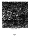
図7及び8は、それぞれ実施例1の繊維膜、試料#8の内表面及び外表面を示すものである。内表面は、渦巻状のパターンからなる繊維構造を示し、外表面は、主として配向した繊維状の構造を呈している。図9及び10は、試料5の繊維膜の内表面及び外表面を示すものである。双方の表面ともに高い気孔率を有し、平滑な領域は存在しない。以上の図面は、種々の高気孔率又は無表皮の表面を示したものであるが、これらは前記浸水押出法による連続的な工程において作製されたものである。本発明における無表皮膜の高い表面気孔率は、フィルター操作中の微粒子によって埋められてしまうことも、汚されてしまうこともほとんどない。これは、本発明の繊維膜が長時間効率よく使用できることを示している。
【0061】
図1は、本発明の中空繊維膜を製造するための、代表的な垂直スピニング工程を示す図である。重合体/溶媒ペースト状混合物は、導入口2を通じて加熱されたバレル押出機1内に、ポンプ手段、例えば、プログレッシブキャビティポンプによって導入される。溶液は、押出機1の加熱バレル内で形成される。押出機1は、加熱された溶液を導管3を通じてメルトポンプ4内に搬送し、前記溶液を導管5を通じてクロスヘッド金型6内に計量する。また、必要に応じて、前記溶液は押出機1から導管3を通じてメルトポンプ4内に搬送し、次いで、導管8を通じて溶液フィルター19内に搬送し、さらに導管5を通じてクロスヘッド金型6に搬送する。
【0062】
前記溶液は、クロスヘッド金型6を通って、金型ノーズ7内に流れる。そこにおいて、前記溶液は、中空繊維形状に形成される。ルーメン液体が金型マンドレル8から金型から排出されている中空繊維溶液の内径部分に導入される。前記ルーメン液体は、ルーメン液体供給手段16によって金型マンドレル8に供給される。
【0063】
垂直繊維紡糸の場合は、ルーメン液体を保持した前記溶液は、金型ノーズ7から垂直方向に、エアーギャップが存在しない状態において冷却浴11内の冷却液体10内に押出される。冷却浴11内において、前記溶液は冷却されて重合体と溶媒とに微視的な相分離を引き起こし、ゲル状の中空繊維膜12となる。ゲル状の中空繊維膜12は、ガイドローラー13によって冷却浴11内を通過した後、Godetロール14によって取り出される。次いで、このゲル状の中空繊維膜12は、クロス巻き付け器15によってGodetロール14から取り除かれる。
【0064】
図2は、本発明の中空繊維膜を製造する水平紡糸工程の代表的な工程図である。重合体/溶媒ペースト状混合物は、加熱されたバレル押出機1内に、ポンプ手段、例えば、プログレッシブキャビティポンプによって導入される。溶液は、押出機1の加熱バレル内で形成される。押出機1は、加熱された溶液を導管3を通じてメルトポンプ4内に搬送し、前記溶液を導管5を通じてクロスヘッド金型6内に計量する。また、必要に応じて、前記溶液は押出機1から導管3を通じてメルトポンプ4内に搬送し、次いで、導管8を通じて溶液フィルター19内に搬送し、さらに導管5を通じてクロスヘッド金型6に搬送する。
【0065】
前記溶液は、クロスヘッド金型6を通って、金型ノーズ7内に流れる。そこにおいて、前記溶液は、中空繊維形状に形成される。ルーメン液体が金型マンドレル8から金型から排出されている中空繊維溶液の内径部分に導入される。前記ルーメン液体は、ルーメン液体供給手段16によって金型マンドレル8に供給される。
【0066】
水平繊維紡糸の場合は、ルーメン液体を保持した前記溶液は、金型ノーズ7から金型/冷却浴絶縁壁9を介して、エアーギャップが存在しない状態において冷却浴11内の冷却液体10内に押出される。冷却浴11内において、前記溶液は冷却されて重合体と溶媒とに微視的な相分離を引き起こし、ゲル状の中空繊維膜12となる。
【0067】
ゲル状の中空繊維膜12は、ガイドローラー13によって冷却浴11内を通過した後、Godetロール14によって取り出される。次いで、このゲル状の中空繊維膜12は、クロス巻き付け器15によってGodetロール14から取り除かれる。
【0068】
溶媒は、中空繊維膜を実質的に脆弱化することがなく、悪影響を及ぼすことのない溶媒を用いて抽出させる。前記繊維膜は、収縮を最小限とする雰囲気下において乾燥される。また、必要に応じて、前記繊維膜は、縦方向に伸長することもでき、また、ヒートセットすることもできる。
【0069】
以上のようにして得られた本発明の過フッ素化熱可塑性多孔質中空繊維膜は、内面及び外面は多孔質となり、少なくともいずれか一方の表面は無表皮の状態となる。そして、この繊維膜は、(以下に記述する)3000秒以下のフロー時間によって特徴づけられる。
【0070】
接触器繊維膜
本発明の接触器繊維膜においては、多孔性膜に対する場合と同じ中空繊維膜製造工程が採用される。但し、工程パラメータの操作範囲においていくらかの違いはある。
【0071】
繊維スピニング溶液中の固体成分量は、25−40%であり、好ましくは28−33%である。ペーストは汎用の2重スクリュー押出機の加熱混合領域に計量され、270−320℃、好ましくは285−310℃に加熱する。繊維膜の押出において、実用的な繊維膜を供するべく、膜壁の厚さは50−250μm、好ましくは100−150μmにする。外径は800−1200μmとし、内径は400−700μmとする。スピンラインの作業能率は、繊維膜の大きさ及び押出速度に依存する。実際には、約20−200フィート/分の作業効率で実施され、好ましくは100−150フィート/分の作業効率で実施する。
【0072】
繊維膜の押出の際においては、金型の内径部分には液体を連続的に流し、ルーメン繊維が崩壊するのを防止するようにしている。繊維膜の大きさにおいて制御できないような変動が生じるのを防止すべく、ルーメン液体流速は注意深く制御することが必要である。また、前記ルーメン液体流速は、金型内若しくは押出された繊維膜内において沸騰しないように、十分に高い沸点を有することが必要である。前記ルーメン液体が沸騰すると、その内部において気泡が生じるとともに、繊維膜の破壊を生ぜしめる。ルーメン液体は、前記繊維膜の内表面を密にすることにより、前記繊維の内壁面に影響を与えないようにする。例えば、ルーメン液体と内壁面との接触界面において前記加熱された溶液を凝固させる、あるいは前記界面から溶媒を抽出し、前記内表面における重合体濃度を増大させることによって行なう。前記ルーメン液体は、室温あるいは約250℃、好ましくは215−235℃の温度に予備加熱した状態で、金型内に計量される。
【0073】
前記金型は、標準的なクロスヘッド金型から構成され、この金型には金型ノーズが取り付けられている。前記金型の2つの温度制御部分を有している。金型のクロスヘッド部分は、270−320℃、好ましくは290−310℃に保持される。前記金型ノーズは、金型出口を含み、290−350℃、好ましくは320−340℃に独立に制御される。前記金型ノーズ加熱領域は、前記溶液温度を前記溶媒の沸点近傍又はそれ以上の温度まで簡単に上昇させることができる。
【0074】
冷却浴は、押出繊維膜の温度を相分離を生ぜしめる上臨界溶液温度以下に減少させる。前記冷却浴液は、繊維膜押出中の金型内に気泡が生じないように、及び表面気孔形成工程に不利な影響を与えないような十分に高い沸点を有する液体から構成される。冷却浴液温度は、25−230℃であり、好ましくは50−150℃である。
【0075】
特性評価方法
(フローレイト速度)
直径1/4インチ、長さ1インチのポリプロピレンチューブに対して繊維膜を巻き付け、2こよりの繊維膜を作製する。次いで、ホットメルト銃を用い、前記チューブの開口端を介したホットメルト接着剤が、前記繊維膜を固定する。通常、前記接着剤は、繊維膜間に入り込まない。前記固定操作を確実なものとすべく、ホットメルト樹脂は、前記チューブの他方の開口部にも塗布される。固定端から巻線の終端までの前記繊維の長さは約3.5cmとする。ホットメルト樹脂が固化した後、繊維ルーメンスが露出するように、前記チューブは切断される。繊維ODは、顕微鏡で測定される。巻線状の繊維膜を具えた前記チューブはテストホルダー内に固定される。イソプロピルアルコール(IPA)が前記ホルダー内に充填され、密閉される。ガス圧力は13.5psiである。IPAの透過量を集積するための時間が記録される。
【0076】
(試料計算)
IPA フローレート=V/(TπODNL)
IPA フロー時間(FT)=所定の体積のIPAを収集するのに要した時間から計算した、IPAの500mlを収集するのに要する秒数
ここで、
V=透過した体積量
T=時間
OD=繊維膜の外径
N=繊維数
L=1よりの露出した繊維の全長
である。
【0077】
(気泡生成の観察)
前記巻線上の固定された繊維膜は、気泡点テストホルダーに取り付けられる。この繊維膜は、IPAが充填されたガラス容器内に浸漬される。空気圧は、繊維膜ルーメン内で徐々に増大する。前記繊維膜の外表面で最初の気泡が発生した時の圧力を気泡生成点として記録する。
【0078】
(平均気泡生成点)
ASTM F316-80と同様の方法を用いて、平均気泡発生点を決定した。繊維膜試料を通じた空気流の流れと圧力との関係を示す曲線を、乾燥試料及びIPAで湿潤させた試料に対して作成した。
平均気泡発生点は、湿潤した空気流が乾燥した空気流の半分の時の圧力である。
【0079】
(SEM像)
中空繊維膜試料をイソプロピルアルコール又はイソプロピルアルコールと水との混合物(50:50)中に浸漬させる。次いで、湿潤した試料を前記アルコールを置換した水内に浸漬する。水で湿潤された試料はツイーザで保持され、液体窒素容器中に浸ける。前記試料を取り出した後、1組のツイーザを用いて曲げることによって折る。約2mmの大きさに切断された試料を導電性カーボン(Structure Probe Inc. West Chester PA)が塗布されたサンプルスタッブに固定する。微細構造観察は、ISI-DS130c 走査型電子顕微鏡(International Scientific Instruments, Inc, Milpitas, CA)を用いて行なった。デジタル化した像は、遅延走査画像取り込み機を用い、TIFフォーマットで記録した。
【0080】
(実施例1)
PTFE/PFVAE共重合体として商標名Hyfron620(Ausimont)とハロゲン化炭素オイルとして商標名HaroVac 60とを混合し、18重量%のペーストを作製した。次いで、このペーストを2重スクリュー押出機であるL/D=13のBaker-Perkins MPC/V中に、Moynoポンプを用いて押出した。その後、水平繊維押出モードの下、200RPMで操作した。押出及び稼働条件は、以下の表1及び2に示す。Zenithメルトポンプを用いて前記熔融物を中空繊維金型内に計量した。この金型の環状部分の大きさは約400μmであった。加熱されたハロゲン化炭素オイル1000Nがルーメン液体として使用され、繊維膜の中空部分を維持するようにした。前記メルトポンプ及び前記ルーメン液体ポンプは、繊維膜の壁面厚さが200μm、ルーメンが500μmとなるように調節した。冷却浴は、ジオクチルフタレートから構成した。ルーメンニードルのセンタリングの後、金型は約1/16インチの深さに前記冷却浴内に浸水され、前記繊維膜は、Godetロールによって取り込まれた。前記繊維膜は、Genesolv 2000(Allid-Signal, Morristown, NJ)で抽出され、乾燥された後、275℃でアニールされた。得られた繊維膜特性は表3に与えられている。
【0081】
【表1】

【表2】
【表3】
(実施例2:伸長の効果)
実施例1と同様にして繊維膜を製造した。すなわち、HalVac 60中におけるPTFE/PEVAE共重合体の18%固溶溶液から、抽出を行ない、100%の伸長を行ない、275℃でアニールした。以下の表において伸長による透過性の改善が示されている。
(実施例3)
テトラフルオロエチレン−過フッ素化メチルビニルエーテル共重合体(A)と、テトラフルオロエチレン−過フッ素化プロピルビニルエーテル共重合体(B)との混合
中空繊維膜は、共重合体(A)及び(B)の3種類の混合体を用い、実施例1と同様の方法で作製した。ペースト内の固体成分は、約20%であった。引き取りは50フィート/分の速度で行なった。冷却浴は、85℃のジオクチルフタレートから構成した。繊維膜の作製条件は、表4及び5に与えられている。繊維膜の特性データは、表6に与えられている。
【0086】
【表4】
【表5】
【表6】
(実施例5:テトラフルオロエチレン−ヘキサフルオロエチレン共重合体(FEP))
FEP中空繊維膜を紡糸する際のプロセス条件は、実施例4の混紡膜のそれぞれと同様に設定した。但し、バレル温度及び金型温度は異なるように設定した。また、20%の固相成分を有するペーストが用いられた。FEPの約258℃の溶解温度は、テトラフルオロエチレン−過フッ素化メチルビニルエチレン共重合体に比較してはるかに低いにもかかわらず、PFA又はPTFE/PFVAE共重合体よりもはるかに溶解性が悪い。FEPを紡糸するために、バレル温度は295−305℃まで上昇させることが必要であり、金型ノーズは300−320℃まで上昇させることが必要である。FEP中空繊維膜の膜特性は、IPAによる気泡生成点が12.6psi、平均気泡生成点が40psi、及びフロー時間が1593秒であった。
【0090】
(比較例)
USP5,032,274の実施例1と同様の工程を経て中空繊維膜を作製したハロゲン化炭化オイル56中にテトラフルオロエチレン−過フッ素化プロピルビニルエーテルが19%含まれた溶液を、重合体に対して溶解性の低いHalocarbon 1000Nの150℃の冷却浴中に押出した。押出バレル温度は、領域1〜4それぞれに対して、150℃、285℃、260℃、及び280℃に設定した。溶解温度は308℃であった。押出機は300rpmの条件で運転した。ルーメン液体ポンプは、28−30rpmで運転した。
【0091】
中空繊維膜の一部を、55フィート/分の速度で引き取ることにより、溶剤で被覆しない状態で作製した。金型出口と冷却浴との間の空気ギャップは、0.25インチとした。得られた繊維膜のODは1500μmであり、壁面厚さは250μmであった。IPAフロー時間は42、735秒であった。
【0092】
中空繊維膜の一部を、50フィート/分の速度で引き取ることにより、溶剤で被覆した状態で作製した。Halocarbon 56は、前記繊維膜とともに押出された。前記空気ギャップは0.50インチとし、前記ODは2000μm、前記壁面厚さは250μmとした。また、IPAフロー時間は3315時間であった。
【0093】
これらの例から、初期の方法によって得た繊維膜では、所望する低フロー時間という特性を実現することができない。フロー時間が低いということは、膜の透過性が高く、フィルタリングに要する時間が短いということを意味する。
【0094】
(実施例6)
本実施例では、上述した30%溶液から作製した無表皮の接触器中空繊維膜を、我々のシリアルナンバー(未だ、承認されていないものであるが)であるMCA 422の方法に従って作製した有表皮の繊維膜と比較した。オゾンを含み、高い水溶性を示すガス混合物をこれらの繊維膜を用いて、水に対して接触させた。
【0095】
無表皮の接触器繊維膜は、次の方法で作製された。Hyflon MFA(Ausimont, Thorofare, NJ)の粉末をHaloVac60(Halocarbon Oil Inc Halocarbon Products Corporation, River Edge, NJ)と混合し、重合体含量が30%のペーストを作製した。その後、このペーストをMoynoメルトポンプ(Springfield, OH)によって、Baker-Perkins
2重スクリュー押出機(Saginaw, MI)に供給された。押出機バレル温度は、180−288℃間の温度に設定した。Zenithメルトポンプ(Waltham,MA)を用いて前記溶解物を前述した中空繊維金型内に計量した。金型の環状部分の大きさは、約300μmであった。ハロゲン化炭素オイル、Halocarbon 60がZenithポンプによってそのルーメン内に供給され、前記繊維膜の中空部分を保持するようにした。前記メルトポンプ及び前記ルーメンオイルポンプは、繊維膜の壁面厚さが約200μm、ルーメンが700μmとなるように調節した。鉱物オイルから構成された冷却浴の温度は、70℃に設定した。ルーメンニードルのセンタリングの後、前記金型は前記冷却浴内に水平に浸漬され、繊維膜は、Godetロールを用いて100フィート/分の速度で引き取った。前記繊維膜は、1,1-ジクロロ-1-フルオロエタン(Florocarbon 141b, Genesolve 2000 Allied-Signal, NJ)で抽出し、次いで乾燥させた。この繊維膜は、IPA気泡生成点が40−50psi以上の値を示し、IPAフロー時間は12、000秒であった。また、これら繊維膜の貫通圧力は、8−10psiであった。
【0096】
各接触器は、図12に示す試験台に設置した。そして、pH6.2、温度23℃の脱イオン水を前記繊維膜のルーメン内にフローレートを種々変化させて送り込んだ。図示しない脱イオン水系からの水は、バイパスバルブ141が閉じられた状態で、バルブ142中に送り込まれる。圧力計150及び151は、接触器を通じた水流圧の減少を測定する。オゾン接触器160は、有表皮膜(102698ユニット)又は無表皮膜(12798ユニット)を含んでいる。Sorbious Semozon 090.2HPオゾンジェネレータからのオゾンガスは、2標準L/分(slpm)の流量で導入口130を介して、接触器ユニット160の外容器内に供給された。接触器ガス圧力は圧力計152で測定され、圧力制御装置180で制御される。出口ガスセンサー112は、出口側のオゾン濃度を計測した。接触器出口流中の分解したオゾンは、オゾンセンサー111で計測する。オーバーフローリンス浴中の分解オゾンは、Orbisphere Model 3600 分解オゾンセンサー110で計測した。液体流は、バルブ140及び導入口液体圧力を調節することによって、3.6−20lpmの間で変化させた。接触器の外容器側のガス圧力は十分に低減されて、ガスが繊維膜を介して液体内に輸送される際に、前記液体内で気泡の生成が生じないようにする。
【0097】
図11は、各接触器の、脱イオン水流量(L/分)に対する出口流中の溶解オゾン量(ppm)をプロットしたものである。これらの結果は、出口流中のオゾン量は、脱イオン水流量が増大するにつれて減少すること、及び無表皮繊維膜接触器は、有表皮接触器(102698)に比べて前記脱イオン水中により多くのオゾンを溶解させることができることを示している。
【0098】
(実施例7)
実施例6における有表皮繊維膜及び無表皮繊維膜を、高水溶性ガスである二酸化炭素について比較検討した。本実施例で用いる各接触器は、束状の繊維膜を作製した後、円筒形のホルダー内に固定して設置して作製した。各接触器においては、ルーメン側を前記繊維膜の外容器すなわち外郭側から分離した。繊維膜IDは500μmであり、繊維膜の壁面厚さは約150μmであった。繊維数は500であり、その長さは43cmであった。接触器は、ガス化効率について試験された。この態様において、Hoechst Liquid Cel脱ガス器によって20℃で脱ガスされた水が繊維膜ルーメン内に送り込まれた。また、空気含有の二酸化炭素が繊維膜の外側を通って、低圧力降下の状態で送り込まれた。実用的な目的のため、ガス圧力の絶対値は760mmHgと仮定した。供給時及び出口水流中のオゾンガス濃度は、流量を変えて測定した。
【0099】
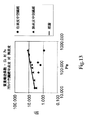
図13においては、その測定結果と、リベーク(Leveque)の式に基づいて理論値とを示している。データ解析法は、以下に示されている。
質量輸送係数Kは、次の式から計算された。
K=-(Q/A)ln[Cout-C*/Cin-C*]
ここで、Coutは、流出液体中における二酸化炭素濃度(ppm)であり、Cinは、流入液体中における二酸化炭素濃度(ppm)であり、C*は、外郭ガス圧力における平衡時の二酸化炭素濃度(ppm)である。また、Qは流量(cc/s)であり、Aは膜面積(cm2)である。
【0100】
シャーウッド(Sherwood)数は次のようにして計算される。
Sh=KD/Dab
ここでKは質量輸送係数(cm/s)であり、Dは繊維膜のID(cm)であり、Dabは水中における二酸化炭素の拡散係数(cm2/s)である。
【0101】
グレーツ(Graetz)数又はペクレ(Peclet)数は次にようにして計算される。
Pe or Gr=VD2/(LDab)
ここで、Vはルーメン内部の流速(cm/s)であり、Lは繊維長(cm)である。
【0102】
前記Sherwood数及び前記Graetz数は、熱及び質量輸送操作を説明するために用いるディメンションの無い量である。前記Sherwood数は、ディメンションの無い質量輸送係数であり、前記Graetz数は、界面層厚さに逆比例するディメンションの無い量である。
【0103】
S.R.Wickramasingheらは、「J.Menbrane Sci. 69」(1992), pp235-250において、Levequeの方法を用いた中空繊維膜における酸素輸送の解析を行なった。この際、1束の中空繊維膜が用いられた。彼らは、Sherwood数のGraetz数に対するプロットが、前記Graetz数が大きいところでは、理論的な予想どおり直線上になることを示した。Graetz数が小さいところにおいては、繊維膜径の不均一性によって説明され、繊維膜を通じた流れの不均一性に影響を及ぼす。彼らの解析は、低Graetz数においては、平均質量輸送係数は、繊維膜を介した不均一の流れに起因して、理論値以下に低下してしまう。彼らは、酸素質量輸送は、前記繊維膜を介した拡散抵抗の影響を受けないと結論づけている。逆に、Levequeの理論に予想に従った繊維膜は、拡散抵抗が非常に高くなって前記理論に従って流れることができないため、多孔質であると結論づけることができる。
【0104】
図13に示された結果は、本実施例の無表皮膜は、高いPeclet数の場合においても、前記Levequeの式に従うため、オゾンに対しては膜抵抗が低いことを示している。直線領域において、Graetz数が5−1000の間では、このGraetz数とSherwood数との相関は、Sh=1.64(Gr)0.33で与えられる。
【図面の簡単な説明】
【図1】 垂直繊維スピニングにおいて用いる金型を示す図である。
【図2】 水平繊維スピニングにおいて用いる金型を示す図である。
【図3】 垂直押出を用いた本発明の製造方法の工程図である。
【図4】 水平押出を用いた本発明の製造方法の工程図である。
【図5】 実施例1に従って作製した、ポリテトラフルオロエチレン−過フッ素化アルキルビニルエーテル共重合体から製造した中空繊維微多孔膜、試料3の内表面を3191倍に拡大した顕微鏡写真である。
【図6】 実施例1に従って作製した、ポリテトラフルオロエチレン−過フッ素化アルキルビニルエーテル共重合体から製造した中空繊維微多孔膜、試料3の外表面を3191倍に拡大した顕微鏡写真である。
【図7】 実施例1に従って作製した、ポリテトラフルオロエチレン−過フッ素化アルキルビニルエーテル共重合体から製造した中空繊維微多孔膜、試料8の内表面を3395倍に拡大した顕微鏡写真である。
【図8】 実施例1に従って作製した、ポリテトラフルオロエチレン−過フッ素化アルキルビニルエーテル共重合体から製造した中空繊維微多孔膜、試料3の外表面を3372倍に拡大した顕微鏡写真である。
【図9】 実施例5に従って作製した、ポリテトラフルオロエチレン−ヘキサフルオロプロピレン(FEP)から製造した中空繊維微多孔膜の内表面を984倍に拡大した顕微鏡写真である。
【図10】 実施例5に従って作製した、ポリテトラフルオロエチレン−ヘキサフルオロプロピレン(FEP)から製造した中空繊維微多孔膜の外表面を1611倍に拡大した顕微鏡写真である。
【図11】 表皮を有する膜から製造した中空繊維膜接触器の性能を、水オゾン化処理により、表皮を有しない膜から作製した接触器の性能と比較したグラフである。
【図12】 液相と液相とが接触した状態において接触器を比較するために用いる試験方法を概略的に示す図である。
【図13】 それぞれ表皮膜及び無表皮膜から製造された接触器の、水中における二酸化炭素の吸着性を比較するための図である。[0001]
[Technical field to which the invention belongs]
The present inventionPerfluorinatedThe present invention relates to a process for producing a microporous hollow fiber membrane from a thermoplastic polymer. In particular, the present invention relates to a process for producing a microporous membrane essentially free of a coating on at least one of an inner surface and an outer surface, and a manufactured fiber membrane.
[0002]
[Prior art]
Microporous membranes are used in a wide range of fields. When used as a separation filter, particles such as dispersions such as buffer solutions, solutions containing therapeutic agents in the pharmaceutical field, microelectronics / wafers / manufacturing processes, and water purification processes can be separated from ultrapure water and organic solvents. Bacteria and the like can be removed. In addition, when the high porosity of the microporous membrane exhibits favorable adsorption and wicking characteristics, it can also be used in the field of medical devices.
[0003]
The hollow fiber membrane can be used as a film contactor, particularly as a film contactor used for degassing and gas adsorption devices. The contactor produces two phases. That is, it is composed of two liquid phases, or a liquid phase and a gas phase, and is configured to transport composition components from one phase to the other. The common process is a mass transport process between the gas phase and the liquid phase, and in this process, components in the gas phase, that is, the air stream are adsorbed in the liquid phase. In the liquid phase degassing step, the liquid phase containing the dissolved gas component is brought into contact with the air, a vacuum atmosphere, or a separated phase, and the dissolved gas component is removed.
[0004]
As an example of conventional gas adsorption, it is possible to generate gas bubbles in the adsorbed liquid phase, increase the interface contact area of the gas phase / liquid phase, and increase the transport rate of the substance to be adsorbed from the gas phase. Conversely, droplets can be sprayed and the liquid phase can be transported through a thin film, such as in a counter-current operation such as a spray tower or pack tower. Similarly, immiscible droplets can be dispersed in the second liquid phase, and transport efficiency can be improved. Filling columns and tray columns have the disadvantage that the individual transport speeds in the two phases cannot be controlled independently without performing operations such as floating and entrainment. However, if the two phases can be separated using a film, the transport speed of the individual phases can be changed independently. Furthermore, the entire area can be utilized even at relatively low transport rates. In view of these advantages, there is an increasing demand for contactors of hollow fiber membranes.
[0005]
Hydrophobic microporous membranes can be used for contactors with aqueous solutions. In this case, the microporous film does not exhibit wettability with respect to the aqueous solution. The aqueous solution flows on one side of the microporous membrane, and the mixed gas having a pressure lower than that of the aqueous solution flows on the other side of the microporous membrane. The pressure on each side of the microporous membrane is maintained so that the pressure of the liquid does not exceed the critical pressure of the membrane and further the gas does not bubble in the liquid. The critical pressure, which is the pressure at which the aqueous solution penetrates into the pores, depends directly on the material constituting the coating, is inversely proportional to the pore size of the coating, and is proportional to the surface tension of the liquid phase in contact with the gas phase.
[0006]
The hollow fiber membrane is mainly used for this purpose because it can seal the above-described device with high density. The sealing density depends on the proportion of the surface area that exhibits a filter action per unit volume of the device. Further, the hollow fiber membrane may function as a feeder in contact with the inner surface or the outer surface of the device. In this case, a more advantageous effect may be shown. When brought into contact with the coating system, dissolved gas components can be removed from the liquid phase, that is, a degassing operation can be performed, and a gaseous substance can be added to the liquid phase. For example, ozone can be added to ultrapure water for cleaning a semiconductor wafer.
[0007]
Microporous membranes can be preferably used for many applications because they exhibit higher mass transportability than non-porous membranes. When used for a liquid having a low surface tension, a material having a relatively small pore diameter is used because the penetration resistance increases. When used for transporting a gas that is soluble at a high concentration in the liquid phase, the mass transport resistance of the coating becomes an obstacle to effective mass transport.
[0008]
Z.Qi and E.L.Cussler are known to have a film resistance of ammonia, SO, in sodium hydroxide solution.2And H2It has been announced that adsorption of gaseous components such as S can be controlled (J. Membrane Sci. 23 (1985) 333-345). This appears to be effective in contactors where the adsorbed liquid is a strong acid or a strong base. In a contactor application, a porous contact film such as a microporous film can be preferably used because it has a film resistance reduced to some extent. When the resistance is so high that the liquid does not enter the hole, it is within a very practical range. The material having an extremely low surface tension used in the present invention can be used without any operation when the fiber surface is covered with a material having a low surface tension, which is an additional and complicated manufacturing process.
[0009]
The advantage of using the microporous membrane or the like for such a contactor isPerfluorinatedThe very low surface tension properties of the resulting polymers can be used with low surface tension liquids. For example, a high corrosion resistance developer used in the field of the semiconductor manufacturing industry may contain a surface tension reducing additive such as a surfactant. Such a developer may penetrate and penetrate into the pores under operating pressure, causing partial loss of the solution and excessive evaporation, so a typical microporous membrane may be degassed. I can't do it.
[0010]
In addition, the pores into which the liquid has entered increase the mass transport resistance against the transport of gaseous components. In USP 5,749,941, conventional hollow fiber membranes such as polypropylene and polyethylene are solution additives for preventing leakage when adsorbing carbon dioxide or hydrogen sulfide in an aqueous solution containing an organic solvent. It is described that it cannot be used unless it is used. PTFE membranes are effective for such applications, but are probably difficult to process into hollow fibers due to their low surface tension. The membrane of the present invention has a surface tension similar to that of PTFE, and a hollow membrane having a small pore diameter can be easily produced.
[0011]
The microporous membrane has a continuous porous structure that penetrates through the membrane. Workers in this field set the hole diameter range from 0.05 μm to 10.0 μm. Such a membrane can be formed into a sheet shape, a tubular shape, or a hollow fiber shape. Hollow fibers have the advantage that they can be incorporated into a densely sealed separation device. The sealing density depends on the ratio of the surface area that acts as a filter to the device volume. The hollow fiber may function as a feeder that contacts the inner surface or the outer surface of the device. In this case, a further advantageous effect is shown.
[0012]
The hollow fiber porous membrane has an outer diameter and an inner diameter corresponding to the thickness of the wall surface constituting the hole. The inner diameter defines the hollow portion of the hollow fiber and is used to introduce a fluid component. And when it feeds through the wall surface of the hole and filtering is performed from the outer surface, it permeates through the wall surface. The hollow interior is sometimes referred to as the “lumen”.
[0013]
The outer surface of the hollow fiber membrane has a skin component and the inner surface has no skin component. The epidermis means a thin dense surface layer combined with a membrane substructure. In a membrane having a skin component, the majority of the flow resistance through the membrane is present in the skin portion. In the microporous membrane, the skin portion has pores that are the basis of the continuous porous structure of the quasistructure. In the microporous membrane having a skin component, the portion occupied by the pores is a small portion of the surface. The membrane having no skin component is porous, and pores are formed on the majority of the surface. The porosity is composed of a single hole or a hole region formed by connecting a single hole. The porosity here means the surface porosity and is defined by the surface area ratio of the whole pores opened on the surface of the membrane.
[0014]
Microporous membranes are classified as symmetric or asymmetric, depending on the uniformity of the pores that penetrate through the membrane. In the case of a hollow fiber membrane, it has a porous wall surface composed of the fibers. In the case of a symmetric fiber membrane, it has a uniform pore size essentially over the entire cross section of the membrane. In the case of an asymmetric fiber membrane, the pore size exhibits a structure distributed over the entire cross section of the membrane. Asymmetry can also be defined from the ratio of the pore diameter of one surface to the pore diameter of the other surface.
[0015]
Manufacturers produce microporous membranes from a variety of materials, and most commonly synthesized polymers are used. Among these polymers, the most important is a thermoplastic polymer. This polymer exhibits fluidity when heated and can be molded. And at the time of cooling, the original solid characteristic can be recovered. When the conditions for using the microporous membrane are severe, the materials that can be used are limited. For example, in the microelectronics industry, organic solvent-based solutions used for wafer coating dissolve or swell most polymer films and make them brittle.
[0016]
High temperature stripping baths in the same field are composed of strong acids and oxidizing compounds. This breaks the polymer film. PolytetrafluoroethylenePerfluorinatedAlkyl vinyl ether copolymers (POLY (PTFE-CO-PFVAE)) or polytetrafluoroethylene-hexafluoropropylene (FEP) are not adversely affected even under harsh use conditions, so chemical and thermal There are advantages over membranes made from polymers that are not very stable.
[0017]
Since it is chemically inert, POLY (PTFE-CO-PFVAE) and FEP polymer are difficult to form into a film using a typical solution casting method. These polymers can be made by using a thermally induced phase separation (TIPS) process. As an example of the TIPS process, the polymer and organic solvent are mixed in an extruder and heated to a temperature at which the polymer decomposes. The membrane is formed by extruding through an extrusion die. The extruded film is cooled and gelled. In the cooling process of the polymer solution, the temperature is lowered to the upper critical solution temperature or lower. At this temperature or below this temperature, two phases are formed from the uniform heated solution. One phase is the phase consisting of the first polymer and the other phase is the phase consisting of the first solvent. Under appropriate conditions, the solvent-rich phase forms a continuous through porous structure. This solvent rich phase is extracted and the selected membrane is dried.
[0018]
POLY (PTFE-CO-PFVAE) and FEP membranes made by the TIPS process are disclosed in USP 4,902,456, USP 4,906,377, USP 4,990,294, and USP 5,032,274. USP 4,902,456 and USP 4,906,377 describe that the membrane has a crack-like opening or a high-density surface phase with single or connecting holes. USP 4,990,294 and USP 5,032,274 disclose that the separation solvent is coated when the molded membrane is present in the mold. In both cases, the membrane surface is composed of a dense surface layer having a porous region. In one example, a film made without coextrusion in sheet formation stretches in the lateral direction. The surface of the film exhibits a nodule structure separated by crack-like openings.
[0019]
USP 5,395,570 discloses making a hollow fiber membrane by extrusion. Specifically, a hollow fiber is extruded together with a lumen filling solution, a coating layer, a cooling solvent, and the like using a quadrupole extrusion head. This method requires a complicated extrusion head and complicated control means. In addition, it is necessary to form a separation coating layer composed of the solvent component between the cooling solvent and the extruded fiber membrane. Furthermore, the extruded fiber membrane is not immediately contacted with the cooling solvent, but is contacted after passing through the lower portion of the extrusion head.
[0020]
USP 4,564,488 discloses a process for preparing porous fibers and a porous membrane. This step includes forming a uniform mixture of the polymer and a solution that is inert to the polymer. The mixture needs to have a temperature range that exhibits complete miscibility and a temperature range that creates a miscibility gap. The mixture is extruded at a temperature above the separation temperature, preferably into a bath containing a wholly or mostly inert liquid. The inside of the bath is kept below the separation temperature. However, it is neither disclosed nor claimed that the homogeneous mixture is immediately extruded into a bath filled entirely or largely with an inert solution. For general-purpose polymers that are within the disclosure of the patent,PerfluorinatedThere is no description regarding the thermoplastic polymer. Nor does it mention a method that requires immediate extrusion from the hot state into the cooling bath.
[0021]
WO95 / 02447 discloses an asymmetric PTFE membrane. This PTFE film was heated to about 340 ° C. on a predetermined substrate.PerfluorinatedThe PTFE solution in cycloalkane is coated, the solvent is removed so that one side of the membrane is less porous than the other side, and the PTFE is cooled. Then, the substrate is removed. There is no mention of using this method for unsupported hollow membranes.
[0022]
USP 4,443,116 discloses a process for making a porous fluorinated polymer structure. Polymers that can be used include tetrafluoroethylene having a fluorinated sulfonyl group (-SO2F), a sulfonate salt (SO3Z), or a carboxyl functional group (COOZ) andPerfluorinatedVinyl ether copolymer. Here, Z represents a cation. Polar functional groups promote solubility. Thermally induced phase separation is used when the solvent must be crystallized after cooling and phase separation. The solvent is removed in the solid state. No data on the porous structure or permeability is given.
[0023]
PTFE, POLY (PTFE-CO-PFVAE), and FEP sheet membranes are disclosed in USP 5,158,680. Therein, an aqueous solution in which particulate PTFE having a particle size of 1 μm or less is dispersed and a filamentous polymer are mixed to form a film and heated to a temperature higher than the melting temperature, and then the filamentous polymer. Is described.
[0024]
In the filtration of ultrapure water, it is necessary that the extraction residual substances are removed from the membrane at a very low level. The TIPS process only requires removal of the low molecular weight extrusion solvent after extrusion. This material can be easily removed by extraction with a solvent. Since POLY (PTFE-CO-PFVAE) and FEP are inactive with respect to the extraction solvent, the membrane characteristics do not change. Due to the porosity of the membrane and the high diffusivity of the low molecular weight solvent, the extraction can be performed easily and completely. Membranes produced by extraction from polymers and resins meet the requirements with the inherent difficulty of removing polymers and resins with slow diffusion rates.
[0025]
Conventional POLY (PTFE-CO-PFVAE) membranes and FEP membranes produced via the TIPS method have been required to be extruded from the air gap. POLY (PTFE-CO-PFVAE) and FEP membranes made by the TIPS process are disclosed in USP 4,902,456, USP 4,906,377, USP 4,990,294, and USP 5,032,274. USP 4,902,456 and USP 4,906,377 describe that the film has a crack-like opening or a high-density surface phase having single holes or connecting holes. USP 4,990,294 and USP 5,032,274 disclose that the separation solvent is coated when the molded membrane is present in the mold. In one example, the sheet-like film expands and contracts in the lateral direction. When the solvent is rapidly evaporated at a high extrusion temperature, a skin portion is generated on the membrane, and the surface porosity cannot be sufficiently controlled.
[0026]
In order to overcome this problem related to the skin, a solvent coating method and a post-stretching method have been adopted by the inventors. In the solvent coating method, a solvent, hot halogenated carbon oil heated to about 300 ° C., is used to coat the surface of the melt as soon as it dissolves in the mold. On the other hand, since this method suppresses evaporation, it causes other process problems. First, since hot halogenated carbon oil tends to form droplets, it is very difficult to uniformly coat the molten surface with a hot solvent. Instead of a uniform coating, the thermal solvent coating may be formed in a streak pattern on the molten surface. After the solution is cooled and solidified, the surface of the membrane exhibits a non-flat porous shape due to the non-uniform application of the solvent. Secondly, the temperature of the oil is not uniform, and the characteristics of the obtained film greatly change due to non-planar cooling and hardening of the surface. Thirdly, the hot oil tends to soften the extruded melt, and the extruded fibers tend to separate and break during processing.
[0027]
It has been disclosed in USP 4,990,294 and USP 5,032,274 that the technique of post-stretching treatment can improve the permeability of PFA membranes having epidermis. Stretching can substantially increase permeability while providing undesirable side effects. First, in order to make stretching effective, it is necessary that the film having the underlying skin portion be uniform in terms of thickness and strength. As the membrane is stretched, the non-uniformity of the underlying membrane is further increased. The reason for this is that under the same stretch strength, the weaker portion will stretch more than the stronger portion. As described above, it is difficult to produce a film using a solvent coating technique. When solvent coating technology is not used, a polymer dried on the die lip can be produced by depositing a large amount of porogen. The deposited dry polymer scratches the surface of the melt and creates linear potential weak spots in the film. In stretching, such a film may be separated and broken from the linear fragile portion.
[0028]
Therefore, it is desirable to rapidly evaporate and remove the solvent from the fiber surface, and it is difficult to use a coating technique or a stretch technique. In order to increase permeability and holding power, it is preferable to use the entire membrane surface as efficiently as possible. For this purpose, it is preferable to manufacture a membrane having a high surface porosity and having no skin portion.
[0029]
Furthermore, it is preferable to use a porous hollow fiber contactor in order to achieve the purpose of transporting a highly soluble gaseous component into the liquid phase having a low surface tension.
[0030]
[Means for Solving the Invention]
The present invention provides a skin-free hollow fiber membrane having a high fluidity and no epidermis, and further a microporous membrane.PerfluorinatedThermoplastic polymers, in particular polytetrafluoroethylene-PerfluorinatedProduced and provided from an alkyl vinyl ether copolymer (POLY (PTFE-CO-PFVAE)) or polytetrafluoroethylene-hexafluoropropylene (FEP). These membranes can be used in harsh chemical environments without causing any problems. When compared to prior art membranes, the membranes of the present invention exhibit high surface porosity and become highly permeable or flowable.
[0031]
As one aspect of the present invention,PerfluorinatedThermoplastic polymers, in particular polytetrafluoroethylenePerfluorinatedProduce and provide porous hollow contactor membranes from alkyl vinyl ether copolymers (POLY (PTFE-CO-PFVAE)) or polytetrafluoroethylene-hexafluoropropylene (FEP), and further provide their use .
[0032]
Also provided are methods of manufacturing these films. This manufacturing method is based on the Thermally Induced Phase Separation (TIPS) method in manufacturing a porous structure and a porous membrane. A mixture of polymer pellets and a solvent such as chlorotrifluoroethylene oligomer, pulverized to a size smaller than that supplied by the manufacturers, is mixed until a paste or paste. The said polymer is mixed so that it may become about 12 to 35 weight%. The solvent is selected such that when the resulting solution is extruded and cooled, film formation occurs in the liquid-liquid phase rather than the solid-liquid phase.
[0033]
A preferred solvent is a saturated low molecular weight polymer of chlorotrifluoroethylene. Specifically, it is the trade name HaloVac60 of Halocarbon Products Corporation, River edge, NJ. In the heating step for forming the upper critical solution temperature, a solvent capable of dissolving the polymer is selected. However, it is required not to boil excessively at that temperature.
[0034]
Fiber extrusion is referred to by spinning, and the length of the extruded fiber from the mold exit to the take-off table is referred to by the spin line. A predetermined amount of the paste is weighed and filled into a heated extruder barrel. Since the inside of the barrel is heated to the upper critical solution temperature or higher, the paste is decomposed. The homogeneous solution is then extruded directly through the annular mold and into the liquid cooling bath. The liquid cooling bath is maintained at a temperature below the upper critical solution temperature of the polymer solution. A preferred liquid cooling bath is one that does not exhibit solubility in the thermoplastic resin even at the extrusion temperature.
[0035]
In the cooling process, the solution formed by heating is phase-separated to form gel-like fibers. The mold tip is slightly sunk with respect to vertical spinning. That is, the spin line is lowered downward. For horizontal spinning, specially designed molds are used. In horizontal spinning, the spin line is maintained in the horizontal direction and is held in a plane at least up to the first guide roll. The mold is firmly fixed to the insulated wall, and the mold chip passes through an opening having a liquid seal in the insulating wall. A trough for cooling the liquid flow is disposed in the recess on the side facing the insulating wall so that the mold nose outlet maintains the above-described depressed state. The cooling medium flows through the trough and overflows into a relatively shallow area of the trough. And the state which the said mold nose exit is immersed in a cooling medium is hold | maintained. In both cases of vertical spinning and horizontal spinning described above, a booster heater and temperature control means are used so that excessive cooling can be prevented and the solution temperature can be easily raised. The decomposed solution is then removed by extraction, and the resulting hollow fiber membrane is dried under conditions that do not cause membrane shrinkage or breakage. The drying temperature is 200-300 ° C.
[0036]
DETAILED DESCRIPTION OF THE INVENTION
Those skilled in the art of producing porous membranes will understand that, according to the teachings of the present invention, a hollow porous membrane without a skin portion can be made from a perfluorinated thermoplastic polymer. Let's go. In the present invention, the abovePerfluorinatedThe thermoplastic resin is dissolved in a solvent to produce a solution having an upper critical solution temperature. Then, when the solution is cooled, it is separated into two phases by liquid phase-liquid phase separation. Such polymers include polytetrafluoroethylene-PerfluorinatedExamples thereof include an alkyl vinyl ether copolymer (POLY (PTFE-CO-PFVAE)) or polytetrafluoroethylene-hexafluoropropylene) (FEP). PFA Teflon (registered trademark) is a polytetrafluoroethylene-PerfluorinatedThis is a specific example of an alkyl vinyl ether copolymer. In this case, most or all of the alkyl groups are propyl groups. FEP Teflon (registered trademark) is a specific example of polytetrafluoroethylene-hexafluoropropylene. Both are provided by DuPont.
[0037]
The trade name Neofron PFA (Daikin Industries) is a polymer similar to the above PFA Teflon (registered trademark). PolytetrafluoroethylenePerfluorinatedThe case where the alkyl group of the alkyl vinyl ether copolymer is mainly a methyl group is described in USP 5,463,006. A preferred polymer is the PTFE / PFVAE copolymer trade name Hyfron 620, available from Ausimont USA, Inc., Thorofare, NJ.
[0038]
For PTFE / PFVAE copolymers, PFA and FEP, a saturated low molecular weight polymer of chlorotrifluoroethylene has been found to be a preferred solvent. Specifically, it is the brand name HaroVac60 provided by Halocarbon Products Corporation, River Edge, NJ.
[0039]
Spinning ingredients
The polymer and the solvent are mixed so that the solvent has a preferable weight ratio with respect to the polymer to form a paste, and the container is filled. The polymer is pulverized into particles having a size of 100 to 1000 μm, preferably 300 μm, by an appropriate pulverization process. If the particle size is too large, it cannot be completely dissolved in the preferred heating step, and heating for a long time is required. If the particle size is too small, a high-cost pulverization process is required, and the entire manufacturing process becomes expensive. The polymer is included at about 12-35% by weight in the mixture. When the content exceeds 35% by weight, the optimum porosity cannot be obtained, and when the content is less than 12% by weight, the strength of the obtained fiber membrane is deteriorated.
[0040]
An example of a saturated low molecular weight polymer of chlorotrifluoroethylene is the trade name HaroVac60 (Halocarbon Products Corporation). The solvent is selected so that it can dissolve the polymer when heated to the upper critical solution temperature. However, it is required not to boil excessively at that temperature. When the polymer is dissolved at a temperature equal to or higher than the boiling point of the solvent, bubbles are generated during extrusion and the spin line is broken. This solvent does not have to be composed purely of a single component; chlorotrifluoroethylene low molecular weight polymers having different molecular weights are mixed with each other, or those having different copolymerization ratios are mixed together. Things can also be used. Such a mixture is adjusted so that solubility and boiling point characteristics are harmonized.
[0041]
Melting and extrusion
The paste is filled in a predetermined amount in a heating and mixing area of a general-purpose double screw extruder, and in order to prevent deterioration of the solvent, a preferable temperature between about 270-320 ° C. in an inert atmosphere, preferably a nitrogen atmosphere, Preferably, heating to 285-310 ° C. This heating temperature depends on the melting temperature of the polymer used. The extruder conveys the heated solution to an in-line heating metering pump, and supplies the solution to an annular mold to control the extrusion speed. An in-line filter can be used as appropriate.
[0042]
Fiber extrusion
When producing a hollow fiber membrane, a difficult situation that does not exist in the production process of the sheet-like membrane is encountered. When the sheet-like film is produced, it is supported in a predetermined state until the target film is solidified. In producing the hollow fiber membrane at a high temperature, the above-mentioned problems become more serious. The hollow fiber membrane is formed by extruding a polymer solution or a polymer dispersion from a groove portion of a mold composed of concentric double tubes. The inner tube transports liquid or gaseous components and maintains an inner diameter that defines the lumen in the solidification process.
[0043]
In actual operation, the polymer solution is coextruded into a liquid bath along with the lumen solution. In the thermally induced phase separation method of the present invention, the liquid bath is maintained at a temperature such that the polymer solution to be used undergoes phase separation. The formed solution is cooled, and after phase separation is performed, the resulting fiber is solidified. Unlike flat sheet membranes that are coated or extruded on a roll or web carrier, or tubular membranes that are formed on the inner or outer surface of a mandrel, extruded hollow fiber membranes are used while solidified. Not supported. Since the extruded solution is not supported, the driving force that transports the fiber through the cooling bath acts directly on the shaped solution as it solidifies. If the driving force is too large, the fibers are separated.
[0044]
There are two interrelated problems that must be overcome in the fiber membrane manufacturing method of the present invention. These are indispensable when producing a highly permeable surfaceless film and when extruding a solution having sufficient strength to be continuously produced at a practical speed.PerfluorinatedThermoplastic resins melt at high temperatures of about 260-300 ° C., but are difficult to dissolve. There are few known solvents that can be dissolved, and even saturated low molecular weight polymers of chlorotrifluoroethylene have some limitations. As the molecular weight increases, the boiling point increases. In the TIPS process, it is commonly recognized that the boiling point of the solvent is 25-100 ° C. higher than the melting temperature of the polymer and that it does not evaporate very much at the extrusion temperature (Lloyd, DRet al, J. Membrane Sci. 64, 1-11 (1991)). However, it cannot be said that the solvent composed of the saturated low molecular weight polymer of chlorotrifluoroethylene having a boiling point higher than about 280 ° C. is suitable for the above-mentioned polymer.
[0045]
Therefore, it is required to be able to use a solvent having a boiling point lower than or equal to the melting temperature of the polymer. At such temperatures, the solvent becomes very volatile. When the air gap is used and the solvent is rapidly lost into the air gap, the polymer concentration on the fiber surface can be increased, and a low-permeability surface film is obtained. In order to prevent skin formation caused by rapid evaporation of the solvent, the mold outlet is submerged in the cooling bath.
[0046]
Although it looks simple in appearance, submerged extrusion is actually extremely difficult in practical use. In the TIPS process, the heated extrudate contacts the cooling surface or cooling bath after passing through the air gap. The air gap is a distance from the mold outlet to the cooling surface or the solidified surface, and plays an extremely important role when the melt is pulled out. Drawing is defined by the ratio of the wall thickness of the membrane to the groove space of the mold. With the air gap, the melt can be drawn out at an accelerated speed, and can be drawn out at a high speed and economical speed. However, in the hollow fiber immersion extrusion, the extruded fibers are rapidly cooled and solidified when being extruded from the mold into the cooling bath. Therefore, the resistance at the time of extraction increases. If it is not completely solidified, it tends to break. Therefore, it is necessary to spin the fiber with a low draw rate.
[0047]
In the present invention, water immersion extrusion can be performed completely, and an air gap or the like is not required. First, to avoid the problems associated with drawing, hollow fiber molds are made with a mold gap that is unusually narrow, about 350-400 μm. This mold gap determines the wall thickness of the fiber membrane. The size of this gap is very close to the final fiber size and requires only a minimal drawing operation. The mold is designed and processed so that only a chip having a size of about 1/16 inch comes into contact with the cooling medium. Such changes are important to ensure the method. Since the temperature of the cooling medium is sufficiently lower than the temperature of the mold body, the temperature of the mold is lowered by immersing the general-purpose mold so that the solution cannot be sufficiently circulated. Even if only the mold chip is submerged, the chip temperature decreases. In this case, a micro thermocouple and a strategically arranged booster heater are used to control the temperature of the mold chip and increase the solution temperature in the mold chip portion.
[0048]
The fibers can be extruded in two ways: horizontal or vertical, as is apparent from FIGS. The solution is metered at a volume ratio through an annular mold by a metering pump to approximately match the working capacity of the spin line. This prevents fiber drawdown and prevents breakage of the fragile extrudate. The inner and outer diameters of the mold and the groove interval are set to a size necessary for obtaining the final fiber. In order to obtain a practical fiber membrane, the wall thickness is 100-250 μm, preferably 150-200 μm. The work efficiency of the spin line depends on the fiber size and extrusion speed. Work speeds of about 20-200 feet / minute can be performed, with a preferred processing speed of 100 feet / minute.
[0049]
During fiber extrusion, the inner diameter of the mold is filled with a continuous fluid to prevent the fiber lumen from collapsing. The flow rate of the lumen liquid is required to be carefully controlled to prevent uncontrollable changes to the fibers. The liquid is required to have a sufficiently high boiling point so that it does not boil in the mold or extruded fiber. Such boiling produces air bubbles in the lumen, causing fiber breakage. By densifying the inner surface of the fiber membrane, the lumen liquid is prevented from affecting the inner wall surface of the fiber membrane. For example, the polymer concentration on the surface is increased by solidifying the heated solution at the contact interface between the lumen liquid and the inner wall surface or by extracting the solvent from the interface. The lumen liquid is metered into the mold at room temperature and preheated to 200 ° C.
[0050]
The mold is composed of a standard crosshead mold, and a mold nose is attached to the mold. This mold has two temperature control regions. The front part of the mold is maintained in a temperature range of 270-320 ° C, preferably 280-290 ° C. The mold nose includes a mold outlet and is controlled at 290-320 ° C, preferably 300-310 ° C. The mold nose heating region can easily raise the solution temperature to near the boiling point of the solvent or higher.
[0051]
Figure3Mold nose used for vertical fiber spinning1Indicates. Solution mold crosshead4Is introduced into the
[0052]
Figure4Mold nose used for horizontal fiber spinning1Indicates. Solution mold crosshead4From the circulation port3Introduced into the mold outlet11Be transported to. Lumen liquid is the inlet2In the mold nose and the mold exit11Discharged from. heater5Holds the solution in a molten state. Temperature sensor6A heater with temperature control device5Is kept at a predetermined temperature of the separation temperature of the solution. Mold chip12The mold nose and the insulation wall of the coolant9Penetrate the cooling bath trough10It is in contact with the cooling liquid 7 held inside. Gel-like hollow fiber membrane8The mold exit11Through moldChip 12And is discharged together with the lumen liquid filling the inner diameter portion of the fiber membrane.
[0053]
In the vertical extrusion, the mold chip is disposed so that the gel-like fiber film to be extruded contacts the cooling bath after passing through the air gap. Preferably, as shown in FIG. 1, it is positioned about 1/16 inch of the submerged mold. In horizontal fiber spinning, the mold is firmly fixed to an insulating wall as shown in FIG. The mold chip penetrates through the opening that gives the sealing property of the liquid to the insulator. The trough for the cooling liquid flow is placed in a recess on the opposite side of the insulation seal so that the mold nose outlet remains submerged. The trough is fixed or retractable. The trough has different depths. If the trough has a uniform depth, for example, the cooling medium overflowed by the pump means can be removed. The cooling medium flows through the trough, overflows in a shallow area within the trough, and maintains the state where the mold nose outlet is submerged by the cooling medium. The trough can be appropriately disposed so that the cooling medium slightly flows between the end surface and the insulating surface.
[0054]
PFA and PTFE / PFVAE copolymers exhibit a chemically similar structure. However, PTFE / PFVAE copolymer is completely different from PFA in terms of productivity. PFA tended to solidify in a very short time due to its high melting temperature. As a result, in submerged extrusion, it was difficult to spin at a high speed of 40-50 fpm unless the lumen liquid was controlled to a temperature within 260-280 ° C. Lumen liquid has a tendency to boil at that temperature, so high speed spinning has been extremely difficult. Under suitable conditions, the maximum spinning speed of PFA was 24.4 m / min (mpm) (80 ft / min). Perhaps due to its relatively low melting temperature, the PTFE / PFVAE copolymer did not solidify in such a short time. The spinning speed could be increased to 55.9 mpm (180 fpm).
[0055]
The gel-like fiber membrane, ie, the fiber membrane that was dried and extracted, was able to stretch in the machine direction and increase the permeability.
[0056]
Cooling bath
The cooling bath lowers the temperature of the extruded fiber membrane to below the upper critical solution temperature and causes phase separation. The cooling liquid is composed of a liquid having a sufficiently high boiling point so as not to generate bubbles when the fiber film is formed by extrusion from a mold and to have no adverse effect on the surface hole forming process. The temperature of the cooling bath is 25-230 ° C, preferably 50-150 ° C.
[0057]
The cooling liquid is required to consist of a liquid that does not boil at the cooling temperature or does not boil when the heated extrudate is placed in the cooling bath. Further, it is necessary to form a skin by reacting with a fiber membrane, or to form a liquid that does not boil at the time when the polymer is decomposed or expanded at the cooling bath temperature. Preferably, dimethyl silicone oil and dioctyl phthalate can be exemplified. Disubstituted phthalates can also be used.
[0058]
Extrusion and drying
The gel-like fiber membrane is introduced into the liquid phase extraction bath, and the solvent is removed without substantial softening, embrittlement, or decomposition of the fiber membrane. Examples of extraction solvents that can be used include dichlorofluoroethane, HCFC-141b, 1,1,2-trichlorotrifluoroethylene (trade name “Freon TF” manufactured by DuPont), hexane, and the like. The extraction is performed at about 20-50 ° C. to minimize the effect of solvent extraction on the fiber membrane. The extracted fiber membrane is dried under conditions that do not shrink. For example, on a cylindrical core at 20-50 ° C. Thereafter, the fiber membrane is heated at 200-300 ° C.
[0059]
The advantage of the submerged extrusion method is that the hollow fiber membrane can be continuously produced to a practical length. Made by conventional methodPerfluorinatedThe thermoplastic hollow fiber membrane was easily broken during the extrusion process, and a practical length could not be obtained. Membranes made by submerged extrusion show good permeability, exhibiting high surface porosity. 5 and 6 show the fiber membrane of Example 1, the inner surface and the outer surface of
[0060]
7 and 8 show the fiber membrane of Example 1 and the inner surface and outer surface of
[0061]
Figure1These are figures which show the typical vertical spinning process for manufacturing the hollow fiber membrane of this invention. The polymer / solvent paste mixture2Heated barrel extruder1Introduced by pump means, for example a progressive cavity pump. Solution extruder1Formed in a heated barrel. Extruder1Conduit the heated solution3Through melt pump4Transported into the conduit with the solution5Through crosshead mold6Weigh in. Also, if necessary, the solution is1From conduit3Through melt pump4Conveyed in, then the conduit8Through solution filter19Transported into the further conduit5Through crosshead mold6Transport to.
[0062]
The solution is a crosshead mold6Through the mold nose7Flows in. There, the solution is formed into a hollow fiber shape. Lumen liquid is mold mandrel8Is introduced into the inner diameter portion of the hollow fiber solution discharged from the mold. The lumen liquid is a lumen liquid supply means.16By mold mandrel8To be supplied.
[0063]
In the case of vertical fiber spinning, the solution holding the lumen liquid is the mold nose.7In the vertical direction from the cooling bath in the absence of an air gap11Inside cooling liquid10Extruded inside. Cooling bath11Inside, the solution is cooled to cause microscopic phase separation between the polymer and the solvent, and the gel-like hollow fiber membrane12It becomes. Gel-like hollow fiber membrane12The guide roller13By cooling bath11Goetet rolls after passing through14Is taken out by. Next, this gel-like hollow fiber membrane12The cross wrap15By Godet Roll14Removed from.
[0064]
Figure2These are the typical process drawings of the horizontal spinning process which manufactures the hollow fiber membrane of this invention. Polymer / solvent pasty mixture heated barrel extruder1Introduced by pump means, for example a progressive cavity pump. Solution extruder1Formed in a heated barrel. Extruder1Conduit the heated solution3Through melt pump4Transported into the conduit with the solution5Through crosshead mold6Weigh in. Also, if necessary, the solution is1From conduit3Through melt pump4Conveyed in, then the conduit8Through solution filter19Transported into the further conduit5Through crosshead mold6Transport to.
[0065]
The solution is a crosshead mold6Through the mold nose7Flows in. There, the solution is formed into a hollow fiber shape. Lumen liquid is mold mandrel8Is introduced into the inner diameter portion of the hollow fiber solution discharged from the mold. The lumen liquid is a lumen liquid supply means.16By mold mandrel8To be supplied.
[0066]
In the case of horizontal fiber spinning, the solution holding the lumen liquid is the mold nose.7To mold / cooling bath insulation wall9Through the cooling bath in the absence of an air gap11Inside cooling liquid10Extruded inside. Cooling bath11Inside, the solution is cooled to cause microscopic phase separation between the polymer and the solvent, and the gel-like hollow fiber membrane12It becomes.
[0067]
Gel-like hollow fiber membrane12The guide roller13By cooling bath11Goetet rolls after passing through14Is taken out by. Next, this gel-like hollow fiber membrane12The cross wrap15By Godet Roll14Removed from.
[0068]
The solvent is extracted using a solvent that does not substantially weaken the hollow fiber membrane and does not adversely affect the membrane. The fiber membrane is dried in an atmosphere that minimizes shrinkage. Moreover, the said fiber membrane can also be extended | stretched to the vertical direction as needed, and can also be heat set.
[0069]
The present invention obtained as described above.PerfluorinatedIn the thermoplastic porous hollow fiber membrane, the inner surface and the outer surface are porous, and at least one of the surfaces is in a skinless state. This fiber membrane is then characterized by a flow time of 3000 seconds or less (described below).
[0070]
Contactor fiber membrane
In the contactor fiber membrane of the present invention, the same hollow fiber membrane production process as that for the porous membrane is employed. However, there are some differences in the operating range of process parameters.
[0071]
The amount of solid component in the fiber spinning solution is 25-40%, preferably 28-33%. The paste is weighed into the heat mixing zone of a general purpose double screw extruder and heated to 270-320 ° C, preferably 285-310 ° C. In the extrusion of the fiber membrane, in order to provide a practical fiber membrane, the thickness of the membrane wall is 50-250 μm, preferably 100-150 μm. The outer diameter is 800-1200 μm, and the inner diameter is 400-700 μm. The work efficiency of the spin line depends on the size of the fiber membrane and the extrusion speed. In practice, it is carried out at a working efficiency of about 20-200 feet / minute, preferably 100-150 feet / minute.
[0072]
In extruding the fiber membrane, a liquid is continuously flowed through the inner diameter portion of the mold to prevent the lumen fiber from collapsing. The lumen liquid flow rate needs to be carefully controlled to prevent uncontrollable fluctuations in the fiber membrane size. The lumen liquid flow rate needs to have a sufficiently high boiling point so as not to boil in the mold or the extruded fiber membrane. When the lumen liquid boils, bubbles are generated inside the lumen liquid and the fiber membrane is destroyed. The lumen liquid does not affect the inner wall surface of the fiber by densifying the inner surface of the fiber membrane. For example, the heating solution is solidified at the contact interface between the lumen liquid and the inner wall surface, or the solvent is extracted from the interface to increase the polymer concentration on the inner surface. The lumen liquid is metered into the mold at room temperature or preheated to about 250 ° C, preferably 215-235 ° C.
[0073]
The mold is composed of a standard crosshead mold, and a mold nose is attached to the mold. It has two temperature control parts of the mold. The crosshead portion of the mold is held at 270-320 ° C, preferably 290-310 ° C. The mold nose includes a mold outlet and is independently controlled at 290-350 ° C, preferably 320-340 ° C. The mold nose heating region can easily raise the solution temperature to near the boiling point of the solvent or higher.
[0074]
The cooling bath reduces the temperature of the extruded fiber membrane below the upper critical solution temperature that causes phase separation. The cooling bath liquid is composed of a liquid having a sufficiently high boiling point so that bubbles are not generated in the mold during fiber membrane extrusion and does not adversely affect the surface pore forming process. The cooling bath liquid temperature is 25-230 ° C, preferably 50-150 ° C.
[0075]
Characterization method
(Flow rate speed)
A fiber membrane is wound around a polypropylene tube having a diameter of 1/4 inch and a length of 1 inch to produce two or more fiber membranes. Next, using a hot melt gun, a hot melt adhesive through the open end of the tube fixes the fiber membrane. Usually, the adhesive does not penetrate between fiber membranes. In order to ensure the fixing operation, the hot melt resin is also applied to the other opening of the tube. The length of the fiber from the fixed end to the end of the winding is about 3.5 cm. After the hot melt resin is solidified, the tube is cut so that the fiber lumen is exposed. The fiber OD is measured with a microscope. The tube having a wound fiber membrane is fixed in a test holder. Isopropyl alcohol (IPA) is filled into the holder and sealed. The gas pressure is 13.5 psi. The time for accumulating the amount of IPA transmission is recorded.
[0076]
(Sample calculation)
IPA flow rate = V / (TπODNL)
IPA flow time (FT) = number of seconds required to collect 500 ml of IPA, calculated from the time taken to collect a given volume of IPA
here,
V = permeated volume
T = time
OD = fiber membrane outer diameter
N = number of fibers
Total exposed fiber length from L = 1
It is.
[0077]
(Observation of bubble formation)
The fixed fiber membrane on the winding is attached to a bubble point test holder. This fiber membrane is immersed in a glass container filled with IPA. Air pressure gradually increases within the fiber membrane lumen. The pressure when the first bubble is generated on the outer surface of the fiber membrane is recorded as the bubble generation point.
[0078]
(Average bubble generation point)
The average bubble generation point was determined using the same method as ASTM F316-80. Curves showing the relationship between airflow flow through the fiber membrane sample and pressure were generated for the dried sample and the sample wetted with IPA.
The average bubble generation point is the pressure when the wet air stream is half of the dry air stream.
[0079]
(SEM image)
The hollow fiber membrane sample is immersed in isopropyl alcohol or a mixture of isopropyl alcohol and water (50:50). Next, the wet sample is immersed in the water substituted with the alcohol. A sample wetted with water is held in a tweezer and immersed in a liquid nitrogen container. After the sample is removed, it is folded by bending using a set of tweezers. A sample cut to a size of about 2 mm is fixed to a sample stub coated with conductive carbon (Structure Probe Inc. West Chester PA). Microstructure observation was performed using an ISI-DS130c scanning electron microscope (International Scientific Instruments, Inc, Milpitas, Calif.). Digitized images were recorded in TIF format using a delayed scan image capture machine.
[0080]
Example 1
The trade name Hyfron 620 (Ausimont) as a PTFE / PFVAE copolymer and the trade name HaroVac 60 as a halogenated carbon oil were mixed to prepare an 18 wt% paste. The paste was then extruded into a double screw extruder L / D = 13 Baker-Perkins MPC / V using a Moyno pump. It was then operated at 200 RPM under horizontal fiber extrusion mode. Extrusion and operating conditions are shown in Tables 1 and 2 below. The melt was weighed into a hollow fiber mold using a Zenith melt pump. The size of the annular portion of this mold was about 400 μm. A heated halogenated carbon oil 1000N was used as the lumen liquid to maintain the hollow portion of the fiber membrane. The melt pump and the lumen liquid pump were adjusted so that the wall thickness of the fiber membrane was 200 μm and the lumen was 500 μm. The cooling bath was composed of dioctyl phthalate. After centering the lumen needle, the mold was submerged in the cooling bath to a depth of about 1/16 inch and the fiber membrane was captured by a Godot roll. The fiber membrane was extracted with Genesolv 2000 (Allid-Signal, Morristown, NJ), dried and then annealed at 275 ° C. The resulting fiber membrane properties are given in Table 3.
[0081]
[Table 1]
[Table 2]
[Table 3]
(Example 2: Effect of elongation)
A fiber membrane was produced in the same manner as in Example 1. That is, extraction was performed from an 18% solid solution of PTFE / PEVAE copolymer in HalVac 60, elongation was performed 100%, and annealing was performed at 275 ° C. The following table shows the improvement in permeability due to stretching.
(Example 3)
TetrafluoroethylenePerfluorinatedMethyl vinyl ether copolymer (A) and tetrafluoroethylene-PerfluorinatedMixing with propyl vinyl ether copolymer (B)
The hollow fiber membrane was produced by the same method as in Example 1 using three types of mixtures of the copolymers (A) and (B). The solid component in the paste was about 20%. The take-up was performed at a speed of 50 feet / minute. The cooling bath was composed of 85 ° C. dioctyl phthalate. Fabrication conditions for the fiber membrane are given in Tables 4 and 5. Fiber membrane property data are given in Table 6.
[0086]
[Table 4]
[Table 5]
[Table 6]
(Example 5: Tetrafluoroethylene-hexafluoroethylene copolymer (FEP))
The process conditions for spinning the FEP hollow fiber membrane were set in the same manner as for each of the blended membranes of Example 4. However, the barrel temperature and the mold temperature were set differently. Also, a paste having 20% solid phase component was used. The melting temperature of FEP about 258 ° C. is tetrafluoroethylene-PerfluorinatedIt is much less soluble than PFA or PTFE / PFVAE copolymer, despite being much lower compared to methyl vinyl ethylene copolymer. In order to spin FEP, the barrel temperature needs to be raised to 295-305 ° C and the mold nose needs to be raised to 300-320 ° C. Regarding the membrane characteristics of the FEP hollow fiber membrane, the bubble generation point by IPA was 12.6 psi, the average bubble generation point was 40 psi, and the flow time was 1593 seconds.
[0090]
(Comparative example)
In the halogenated carbonized oil 56 in which a hollow fiber membrane was produced through the same steps as in Example 1 of USP 5,032,274, tetrafluoroethylene-PerfluorinatedA solution containing 19% propyl vinyl ether was extruded into a 150 ° C. cooling bath of Halocarbon 1000N, which is poorly soluble in the polymer. The extrusion barrel temperature was set to 150 ° C., 285 ° C., 260 ° C., and 280 ° C. for each of regions 1-4. The dissolution temperature was 308 ° C. The extruder was operated at 300 rpm. The lumen liquid pump was operated at 28-30 rpm.
[0091]
A portion of the hollow fiber membrane was drawn off at a rate of 55 feet / min to make it uncoated with a solvent. The air gap between the mold outlet and the cooling bath was 0.25 inches. The obtained fiber membrane had an OD of 1500 μm and a wall thickness of 250 μm. The IPA flow time was 42,735 seconds.
[0092]
A part of the hollow fiber membrane was taken up at a rate of 50 feet / minute, and was prepared in a state of being coated with a solvent. Halocarbon 56 was extruded with the fiber membrane. The air gap was 0.50 inch, the OD was 2000 μm, and the wall thickness was 250 μm. The IPA flow time was 3315 hours.
[0093]
From these examples, the desired low flow time characteristic cannot be realized with the fiber membrane obtained by the initial method. Low flow time means high membrane permeability and short filtering time.
[0094]
(Example 6)
In this example, a non-skin contactor hollow fiber membrane prepared from the 30% solution described above was prepared according to the method of MCA 422, which is our serial number (although not yet approved). The fiber membrane was compared. A gas mixture containing ozone and exhibiting high water solubility was brought into contact with water using these fiber membranes.
[0095]
A non-skin contactor fiber membrane was prepared by the following method. Hyflon MFA (Ausimont, Thorofare, NJ) powder was mixed with HaloVac60 (Halocarbon Oil Inc, Halocarbon Products Corporation, River Edge, NJ) to produce a paste with a polymer content of 30%. The paste is then applied to a Baker-Perkins by a Moyno melt pump (Springfield, OH).
Feeded to a double screw extruder (Saginaw, MI). The extruder barrel temperature was set to a temperature between 180-288 ° C. The melt was weighed into the hollow fiber mold described above using a Zenith melt pump (Waltham, MA). The size of the annular portion of the mold was about 300 μm. A halogenated carbon oil, Halocarbon 60, was fed into the lumen by a Zenith pump to hold the hollow portion of the fiber membrane. The melt pump and the lumen oil pump were adjusted so that the wall thickness of the fiber membrane was about 200 μm and the lumen was 700 μm. The temperature of the cooling bath composed of mineral oil was set to 70 ° C. After centering the lumen needle, the mold was immersed horizontally in the cooling bath, and the fiber membrane was pulled at a rate of 100 feet / minute using a Godot roll. The fiber membrane was extracted with 1,1-dichloro-1-fluoroethane (Florocarbon 141b, Genesolve 2000 Allied-Signal, NJ) and then dried. This fiber membrane had an IPA bubble generation point of 40-50 psi or more and an IPA flow time of 12,000 seconds. Moreover, the penetration pressure of these fiber membranes was 8-10 psi.
[0096]
Each contactor was installed in the test stand shown in FIG. Then, deionized water having a pH of 6.2 and a temperature of 23 ° C. was fed into the lumen of the fiber membrane with various flow rates changed. Water from a deionized water system (not shown) is fed into the
[0097]
FIG. 11 is a plot of the dissolved ozone amount (ppm) in the outlet flow versus deionized water flow rate (L / min) for each contactor. These results show that the amount of ozone in the outlet stream decreases as the deionized water flow rate increases, and that the non-skinned fiber membrane contactor is more in the deionized water than the skinned contactor (102698). It is shown that ozone can be dissolved.
[0098]
(Example 7)
The surfaced and non-skinned fiber membranes in Example 6 were compared for carbon dioxide, which is a highly water-soluble gas. Each contactor used in this example was produced by producing a bundle-like fiber membrane and then fixing and installing it in a cylindrical holder. In each contactor, the lumen side was separated from the outer container of the fiber membrane, that is, the outer side. The fiber membrane ID was 500 μm, and the wall thickness of the fiber membrane was about 150 μm. The number of fibers was 500, and the length was 43 cm. The contactor was tested for gasification efficiency. In this embodiment, water degassed by a Hoechst Liquid Cel degasser at 20 ° C. was fed into the fiber membrane lumen. Air-containing carbon dioxide was sent through the outside of the fiber membrane with a low pressure drop. For practical purposes, the absolute value of the gas pressure was assumed to be 760 mmHg. The ozone gas concentration at the time of supply and in the outlet water flow was measured by changing the flow rate.
[0099]
In FIG. 13, the measurement result and the theoretical value are shown based on the Reeve equation. The data analysis method is shown below.
The mass transport coefficient K was calculated from the following formula.
K =-(Q / A) ln [Cout-C*/ Cin-C*]
Here, Cout is the carbon dioxide concentration (ppm) in the effluent liquid, Cin is the carbon dioxide concentration (ppm) in the inflow liquid, and C*Is the carbon dioxide concentration (ppm) at equilibrium at the outer gas pressure. Q is the flow rate (cc / s) and A is the membrane area (cm2).
[0100]
The Sherwood number is calculated as follows:
Sh = KD / Dab
Where K is the mass transport coefficient (cm / s), D is the fiber membrane ID (cm), and Dab is the diffusion coefficient of carbon dioxide in water (cm2/ s).
[0101]
The Graetz number or Peclet number is calculated as follows.
Pe or Gr = VD2/ (LDab)
Here, V is the flow velocity (cm / s) inside the lumen, and L is the fiber length (cm).
[0102]
The Sherwood number and Graetz number are dimensionless quantities used to describe heat and mass transport operations. The Sherwood number is a dimensionless mass transport coefficient, and the Graetz number is a dimensionless quantity that is inversely proportional to the interface layer thickness.
[0103]
S.R.Wickramasinghe et al. Analyzed oxygen transport in hollow fiber membranes using the Leveque method in “J. Menbrane Sci. 69” (1992), pp235-250. At this time, a bundle of hollow fiber membranes was used. They showed that the plot of Sherwood number versus Graetz number was linear as theoretically expected where the Graetz number was large. Where the Graetz number is small, this is explained by the non-uniformity of the fiber membrane diameter and affects the non-uniformity of the flow through the fiber membrane. Their analysis shows that at low Graetz numbers, the average mass transport coefficient drops below the theoretical value due to non-uniform flow through the fiber membrane. They conclude that oxygen mass transport is not affected by diffusion resistance through the fiber membrane. On the contrary, it can be concluded that the fiber membrane according to the expectation of Leveque's theory is porous because the diffusion resistance is so high that it cannot flow according to the theory.
[0104]
The results shown in FIG. 13 indicate that the surfaceless film of this example has a low membrane resistance against ozone because it follows the above-mentioned Leveque equation even in the case of a high Peclet number. In the linear region, when the Graetz number is between 5 and 1000, the correlation between this Graetz number and the Sherwood number is Sh = 1.64 (Gr)0.33Given in.
[Brief description of the drawings]
[FIG.]It is a figure which shows the metal mold | die used in vertical fiber spinning.
[FIG.]It is a figure which shows the metal mold | die used in horizontal fiber spinning.
[FIG.]It is process drawing of the manufacturing method of this invention using vertical extrusion.
[FIG.]It is process drawing of the manufacturing method of this invention using horizontal extrusion.
5 is a photomicrograph at 3191 times of the inner surface of a hollow fiber microporous membrane produced from a polytetrafluoroethylene-perfluorinated alkyl vinyl ether copolymer prepared according to Example 1 and
6 is a photomicrograph of the outer surface of a hollow fiber microporous membrane manufactured from a polytetrafluoroethylene-perfluorinated alkyl vinyl ether copolymer prepared according to Example 1 and
7 is a photomicrograph of the hollow fiber microporous membrane prepared from polytetrafluoroethylene-perfluorinated alkyl vinyl ether copolymer prepared according to Example 1 and the inner surface of
8 is a photomicrograph of the outer surface of a hollow fiber microporous membrane manufactured from a polytetrafluoroethylene-perfluorinated alkyl vinyl ether copolymer prepared according to Example 1 and
9 is a photomicrograph at 984 times magnification of the inner surface of a hollow fiber microporous membrane produced from polytetrafluoroethylene-hexafluoropropylene (FEP) produced according to Example 5. FIG.
10 is a photomicrograph of the outer surface of a hollow fiber microporous membrane produced from polytetrafluoroethylene-hexafluoropropylene (FEP) produced according to Example 5 at a magnification of 1611 times. FIG.
FIG. 11 is a graph comparing the performance of a hollow fiber membrane contactor made from a membrane having a skin with the performance of a contactor made from a membrane not having a skin by water ozonization.
FIG. 12 is a diagram schematically showing a test method used for comparing contactors in a state where a liquid phase and a liquid phase are in contact with each other.
FIG. 13 is a diagram for comparing the adsorptivity of carbon dioxide in water of contactors manufactured from a surface film and a surfaceless film, respectively.
Claims (12)
(a)前記過フッ素化熱可塑性重合体を、この重合体と上臨界溶液温度を形成する溶媒中に溶解する工程と、
(b)得られた溶液を、その一部分が鉱物オイル、ハロゲン化炭素、ジメチルシリコーンオイル及びジ置換フタレートからなる群から選択される冷却浴中に浸漬され、前記溶液の前以て冷却されるのを防止するべく十分高い温度に保持された環状の金型内に押出す工程と、
(c)前記溶液を前記冷却浴中に押出す工程と、
(d)前記溶液を前記上臨界溶液温度以下にまで冷却して、重合体リッチな固相と溶媒リッチな液相との2相に、液相−液相分離し、ゲル状の繊維を作製する工程と、
(e)前記溶媒をジクロロフルオロエタン、HCFC−141b、1,1,2−トリクロロフルオロエチレン及びヘキサンからなる群から選択される抽出溶媒を用いて前記ゲル状繊維から抽出して多孔質の中空繊維膜を形成する工程と、
(f)前記多孔質中空繊維膜を制止条件下で、乾燥する工程と、を含むことを特徴とする、中空繊維多孔質膜の作製方法。A method of producing a hollow fiber porous membrane that is substantially skinless on at least one surface from a perfluorinated thermoplastic polymer,
(A) dissolving the perfluorinated thermoplastic polymer in a solvent that forms an upper critical solution temperature with the polymer;
(B) The resulting solution is immersed in a cooling bath, a portion of which is selected from the group consisting of mineral oil, halogenated carbon, dimethyl silicone oil and disubstituted phthalate, and cooled in advance of the solution. Extruding into an annular mold held at a sufficiently high temperature to prevent
(C) extruding the solution into the cooling bath;
(D) The solution is cooled to the upper critical solution temperature or lower, and liquid phase-liquid phase separation is performed into two phases of a polymer-rich solid phase and a solvent-rich liquid phase to produce gel-like fibers. And the process of
(E) Porous hollow fibers extracted from the gel fibers using an extraction solvent selected from the group consisting of dichlorofluoroethane, HCFC-141b, 1,1,2-trichlorofluoroethylene and hexane Forming a film;
(F) the porous hollow fiber membrane with restraining conditions, comprising the the steps of drying, a method for manufacturing a hollow fiber porous membrane.
Applications Claiming Priority (3)
| Application Number | Priority Date | Filing Date | Title |
|---|---|---|---|
| US11785299P | 1999-01-29 | 1999-01-29 | |
| US60/117,852 | 1999-01-29 | ||
| PCT/US2000/002198 WO2000044484A2 (en) | 1999-01-29 | 2000-01-27 | Microporous hollow fiber membranes from perfluorinated thermoplastic polymers |
Related Child Applications (1)
| Application Number | Title | Priority Date | Filing Date |
|---|---|---|---|
| JP2009166295A Division JP2009279585A (en) | 1999-01-29 | 2009-07-15 | Hollow fiber porous membrane from perfluorinated thermoplastic polymer |
Publications (3)
| Publication Number | Publication Date |
|---|---|
| JP2002535132A JP2002535132A (en) | 2002-10-22 |
| JP2002535132A5 JP2002535132A5 (en) | 2007-03-01 |
| JP4447790B2 true JP4447790B2 (en) | 2010-04-07 |
Family
ID=22375178
Family Applications (3)
| Application Number | Title | Priority Date | Filing Date |
|---|---|---|---|
| JP2000595775A Expired - Lifetime JP4447790B2 (en) | 1999-01-29 | 2000-01-27 | Microporous hollow fibers formed from perfluorinated thermoplastic polymers |
| JP2009166295A Pending JP2009279585A (en) | 1999-01-29 | 2009-07-15 | Hollow fiber porous membrane from perfluorinated thermoplastic polymer |
| JP2014038551A Pending JP2014144454A (en) | 1999-01-29 | 2014-02-28 | Microporous hollow fiber membranes formed from perfluorinated thermoplastic polymers |
Family Applications After (2)
| Application Number | Title | Priority Date | Filing Date |
|---|---|---|---|
| JP2009166295A Pending JP2009279585A (en) | 1999-01-29 | 2009-07-15 | Hollow fiber porous membrane from perfluorinated thermoplastic polymer |
| JP2014038551A Pending JP2014144454A (en) | 1999-01-29 | 2014-02-28 | Microporous hollow fiber membranes formed from perfluorinated thermoplastic polymers |
Country Status (8)
| Country | Link |
|---|---|
| EP (1) | EP1144097B1 (en) |
| JP (3) | JP4447790B2 (en) |
| KR (1) | KR100686676B1 (en) |
| AU (1) | AU2975600A (en) |
| DE (1) | DE60036857T2 (en) |
| ES (1) | ES2292433T3 (en) |
| TW (1) | TW476660B (en) |
| WO (1) | WO2000044484A2 (en) |
Families Citing this family (11)
| Publication number | Priority date | Publication date | Assignee | Title |
|---|---|---|---|---|
| US6582496B1 (en) | 2000-01-28 | 2003-06-24 | Mykrolis Corporation | Hollow fiber membrane contactor |
| US6802972B1 (en) | 1999-01-29 | 2004-10-12 | Mykrolis Corporation | Microporous hollow fiber membranes from perfluorinated thermoplastic polymers |
| US6663745B1 (en) | 1999-01-29 | 2003-12-16 | Mykrolis Corporation | Method for manufacturing hollow fiber membranes |
| US6921482B1 (en) | 1999-01-29 | 2005-07-26 | Mykrolis Corporation | Skinned hollow fiber membrane and method of manufacture |
| US7347937B1 (en) | 2000-01-28 | 2008-03-25 | Entegris, Inc. | Perfluorinated thermoplastic filter cartridge |
| JP4252456B2 (en) * | 2001-11-02 | 2009-04-08 | ミリポア・コーポレイション | Membrane adsorption device |
| JP4498748B2 (en) * | 2002-03-19 | 2010-07-07 | インテグリス・インコーポレーテッド | Hollow fiber membrane contactor and process |
| CN102247763B (en) * | 2011-07-11 | 2013-07-10 | 林衍良 | Method and device for manufacturing hollow fiber membrane |
| TWI613999B (en) * | 2012-08-30 | 2018-02-11 | 財團法人工業技術研究院 | Ozone-disinfecting hand-held device, method, cover, ozone-concentration detecting module and method |
| WO2019181435A1 (en) * | 2018-03-22 | 2019-09-26 | 富士フイルム株式会社 | Filter device, purification device, chemical solution production method |
| CN110935194B (en) * | 2019-12-12 | 2021-08-06 | 中国计量大学 | Micro-extraction system of hollow fiber membrane |
Family Cites Families (9)
| Publication number | Priority date | Publication date | Assignee | Title |
|---|---|---|---|---|
| JPS5771409A (en) * | 1980-10-20 | 1982-05-04 | Terumo Corp | Preparation of hollow fiber |
| JPH0670155B2 (en) * | 1987-11-13 | 1994-09-07 | 東レ株式会社 | Manufacturing method of polytetrafluoroethylene resin porous membrane |
| DE3878899T2 (en) * | 1987-07-30 | 1993-07-22 | Toray Industries | POROESE POLYTETRAFLUORAETHYLENE MEMBRANE, SEPARATING DEVICE USING THIS MEMBRANE AND METHOD FOR THE PRODUCTION THEREOF. |
| JPH0653215B2 (en) * | 1987-08-13 | 1994-07-20 | 東レ株式会社 | Hollow fiber module and method for producing the same |
| US5032274A (en) * | 1988-05-04 | 1991-07-16 | Millipore Corporation | Process for producing fluorocarbon membranes and membrane product |
| US4906377A (en) * | 1988-05-04 | 1990-03-06 | Millipore Corporation | Fluorocarbon membranes and process for making fluorocarbon membranes |
| US4902456A (en) * | 1988-05-04 | 1990-02-20 | Millipore Corporation | Fluorocarbon membranes and process for making fluorocarbon membranes |
| US4990294A (en) * | 1988-05-04 | 1991-02-05 | Millipore Corporation | Process for producing fluorocarbon membranes and membrane product |
| US4970034A (en) * | 1988-09-23 | 1990-11-13 | W. R. Grace & Co.-Conn. | Process for preparing isotropic microporous polysulfone membranes |
-
2000
- 2000-01-27 ES ES00908409T patent/ES2292433T3/en not_active Expired - Lifetime
- 2000-01-27 KR KR1020017009515A patent/KR100686676B1/en active IP Right Grant
- 2000-01-27 AU AU29756/00A patent/AU2975600A/en not_active Abandoned
- 2000-01-27 EP EP00908409A patent/EP1144097B1/en not_active Expired - Lifetime
- 2000-01-27 JP JP2000595775A patent/JP4447790B2/en not_active Expired - Lifetime
- 2000-01-27 DE DE60036857T patent/DE60036857T2/en not_active Expired - Lifetime
- 2000-01-27 WO PCT/US2000/002198 patent/WO2000044484A2/en active IP Right Grant
- 2000-01-28 TW TW089101500A patent/TW476660B/en not_active IP Right Cessation
-
2009
- 2009-07-15 JP JP2009166295A patent/JP2009279585A/en active Pending
-
2014
- 2014-02-28 JP JP2014038551A patent/JP2014144454A/en active Pending
Also Published As
| Publication number | Publication date |
|---|---|
| DE60036857D1 (en) | 2007-12-06 |
| ES2292433T3 (en) | 2008-03-16 |
| DE60036857T2 (en) | 2008-07-31 |
| TW476660B (en) | 2002-02-21 |
| KR100686676B1 (en) | 2007-02-27 |
| WO2000044484A2 (en) | 2000-08-03 |
| JP2009279585A (en) | 2009-12-03 |
| AU2975600A (en) | 2000-08-18 |
| KR20010101764A (en) | 2001-11-14 |
| EP1144097A3 (en) | 2001-12-05 |
| WO2000044484A3 (en) | 2000-12-21 |
| EP1144097B1 (en) | 2007-10-24 |
| JP2002535132A (en) | 2002-10-22 |
| JP2014144454A (en) | 2014-08-14 |
| EP1144097A2 (en) | 2001-10-17 |
Similar Documents
| Publication | Publication Date | Title |
|---|---|---|
| JP2014144454A (en) | Microporous hollow fiber membranes formed from perfluorinated thermoplastic polymers | |
| Kong et al. | Preparation of PVDF hollow‐fiber membranes via immersion precipitation | |
| JP2015061727A (en) | Skin-formed hollow fiber membrane and production method thereof | |
| JP2548092B2 (en) | Fluorocarbon film manufacturing method | |
| US6805731B2 (en) | Hollow fiber membrane contactor | |
| EP0527913B1 (en) | Method for making pvdf hollow fibre membranes | |
| US6977043B2 (en) | Skinned hollow fiber membrane and method of manufacture | |
| JP5093941B2 (en) | Hollow fiber membrane contactor | |
| US6802972B1 (en) | Microporous hollow fiber membranes from perfluorinated thermoplastic polymers | |
| CN113144909A (en) | Poly 4-methyl-1-pentene hollow fiber membrane applied to ECMO and preparation method thereof | |
| JP2002535132A5 (en) | Microporous hollow fiber membrane formed from perfluorinated thermoplastic polymer | |
| RU2652212C1 (en) | Hollow fiber membrane | |
| AU653528B2 (en) | Porous PVdF membranes | |
| JPS6190704A (en) | Hollow yarn membrane |
Legal Events
| Date | Code | Title | Description |
|---|---|---|---|
| A711 | Notification of change in applicant |
Free format text: JAPANESE INTERMEDIATE CODE: A711 Effective date: 20040506 |
|
| RD04 | Notification of resignation of power of attorney |
Free format text: JAPANESE INTERMEDIATE CODE: A7424 Effective date: 20061116 |
|
| A711 | Notification of change in applicant |
Free format text: JAPANESE INTERMEDIATE CODE: A712 Effective date: 20061110 |
|
| A524 | Written submission of copy of amendment under section 19 (pct) |
Free format text: JAPANESE INTERMEDIATE CODE: A524 Effective date: 20070112 |
|
| A621 | Written request for application examination |
Free format text: JAPANESE INTERMEDIATE CODE: A621 Effective date: 20070112 |
|
| A977 | Report on retrieval |
Free format text: JAPANESE INTERMEDIATE CODE: A971007 Effective date: 20080606 |
|
| A131 | Notification of reasons for refusal |
Free format text: JAPANESE INTERMEDIATE CODE: A131 Effective date: 20080617 |
|
| A601 | Written request for extension of time |
Free format text: JAPANESE INTERMEDIATE CODE: A601 Effective date: 20080910 |
|
| A602 | Written permission of extension of time |
Free format text: JAPANESE INTERMEDIATE CODE: A602 Effective date: 20080918 |
|
| A521 | Written amendment |
Free format text: JAPANESE INTERMEDIATE CODE: A523 Effective date: 20081215 |
|
| A02 | Decision of refusal |
Free format text: JAPANESE INTERMEDIATE CODE: A02 Effective date: 20090331 |
|
| A521 | Written amendment |
Free format text: JAPANESE INTERMEDIATE CODE: A523 Effective date: 20090715 |
|
| A911 | Transfer to examiner for re-examination before appeal (zenchi) |
Free format text: JAPANESE INTERMEDIATE CODE: A911 Effective date: 20090810 |
|
| A131 | Notification of reasons for refusal |
Free format text: JAPANESE INTERMEDIATE CODE: A131 Effective date: 20091027 |
|
| A521 | Written amendment |
Free format text: JAPANESE INTERMEDIATE CODE: A523 Effective date: 20091203 |
|
| TRDD | Decision of grant or rejection written | ||
| A01 | Written decision to grant a patent or to grant a registration (utility model) |
Free format text: JAPANESE INTERMEDIATE CODE: A01 Effective date: 20100105 |
|
| A01 | Written decision to grant a patent or to grant a registration (utility model) |
Free format text: JAPANESE INTERMEDIATE CODE: A01 |
|
| A61 | First payment of annual fees (during grant procedure) |
Free format text: JAPANESE INTERMEDIATE CODE: A61 Effective date: 20100121 |
|
| FPAY | Renewal fee payment (event date is renewal date of database) |
Free format text: PAYMENT UNTIL: 20130129 Year of fee payment: 3 |
|
| R150 | Certificate of patent or registration of utility model |
Ref document number: 4447790 Country of ref document: JP Free format text: JAPANESE INTERMEDIATE CODE: R150 Free format text: JAPANESE INTERMEDIATE CODE: R150 |
|
| FPAY | Renewal fee payment (event date is renewal date of database) |
Free format text: PAYMENT UNTIL: 20130129 Year of fee payment: 3 |
|
| S531 | Written request for registration of change of domicile |
Free format text: JAPANESE INTERMEDIATE CODE: R313531 |
|
| FPAY | Renewal fee payment (event date is renewal date of database) |
Free format text: PAYMENT UNTIL: 20130129 Year of fee payment: 3 |
|
| R350 | Written notification of registration of transfer |
Free format text: JAPANESE INTERMEDIATE CODE: R350 |
|
| R250 | Receipt of annual fees |
Free format text: JAPANESE INTERMEDIATE CODE: R250 |
|
| R250 | Receipt of annual fees |
Free format text: JAPANESE INTERMEDIATE CODE: R250 |
|
| R250 | Receipt of annual fees |
Free format text: JAPANESE INTERMEDIATE CODE: R250 |
|
| R250 | Receipt of annual fees |
Free format text: JAPANESE INTERMEDIATE CODE: R250 |
|
| R250 | Receipt of annual fees |
Free format text: JAPANESE INTERMEDIATE CODE: R250 |
|
| R250 | Receipt of annual fees |
Free format text: JAPANESE INTERMEDIATE CODE: R250 |
|
| R250 | Receipt of annual fees |
Free format text: JAPANESE INTERMEDIATE CODE: R250 |
|
| EXPY | Cancellation because of completion of term |