JP4445919B2 - Disc loading device - Google Patents

Disc loading device Download PDF

Info

Publication number
JP4445919B2
JP4445919B2 JP2005359145A JP2005359145A JP4445919B2 JP 4445919 B2 JP4445919 B2 JP 4445919B2 JP 2005359145 A JP2005359145 A JP 2005359145A JP 2005359145 A JP2005359145 A JP 2005359145A JP 4445919 B2 JP4445919 B2 JP 4445919B2
Authority
JP
Japan
Prior art keywords
disk
lever
diameter disk
disc
diameter
Prior art date
Legal status (The legal status is an assumption and is not a legal conclusion. Google has not performed a legal analysis and makes no representation as to the accuracy of the status listed.)
Expired - Fee Related
Application number
JP2005359145A
Other languages
Japanese (ja)
Other versions
JP2006196148A (en
JP2006196148A5 (en
Inventor
則勝 吉田
和雄 石川
幸生 森岡
卓人 山崎
Current Assignee (The listed assignees may be inaccurate. Google has not performed a legal analysis and makes no representation or warranty as to the accuracy of the list.)
Panasonic Corp
Panasonic Holdings Corp
Original Assignee
Panasonic Corp
Matsushita Electric Industrial Co Ltd
Priority date (The priority date is an assumption and is not a legal conclusion. Google has not performed a legal analysis and makes no representation as to the accuracy of the date listed.)
Filing date
Publication date
Application filed by Panasonic Corp, Matsushita Electric Industrial Co Ltd filed Critical Panasonic Corp
Priority to JP2005359145A priority Critical patent/JP4445919B2/en
Publication of JP2006196148A publication Critical patent/JP2006196148A/en
Publication of JP2006196148A5 publication Critical patent/JP2006196148A5/ja
Application granted granted Critical
Publication of JP4445919B2 publication Critical patent/JP4445919B2/en
Expired - Fee Related legal-status Critical Current
Anticipated expiration legal-status Critical

Links

Images

Description

本発明は、ディスク状の記録媒体を装置内に挿入し、ディスク装着位置に装着するディスクローディング装置(ディスク駆動装置)に関する。   The present invention relates to a disk loading device (disk drive device) for inserting a disk-shaped recording medium into a device and mounting it at a disk mounting position.

ディスクローディング装置は、音響用の光ディスクであるCD及び映像用の光ディスクであるDVDをはじめ、コンピュータ用の各種光ディスクに光学的にデータを記録再生をするために、当該ディスクを装置内に挿入し、ディスク装着位置に装着する装置として広い分野で使用されている。前記のような光ディスクの内、ケースに入っておらずディスク単体で使用される光ディスクとしては、規格直径が12cmのディスク(大径ディスク)と8cmのディスク(小径ディスク)の2種類が広く普及している。そのためディスクローディング装置として、前記の大径ディスクと小径ディスクの両方を駆動できる両用型のディスクローディング装置が実用化されている。   The disc loading device inserts the disc into the device in order to optically record and reproduce data on various optical discs for computers, such as a CD that is an optical disc for audio and a DVD that is an optical disc for video. It is used in a wide field as a device for mounting at a disk mounting position. Of the optical discs described above, two types of optical discs that are not included in the case and are used as a single disc, a standard diameter disc of 12 cm (large diameter disc) and an 8 cm disc (small diameter disc), are widely used. ing. Therefore, as a disk loading apparatus, a dual-purpose disk loading apparatus capable of driving both the large diameter disk and the small diameter disk has been put into practical use.

両用型のディスクローディング装置では、ディスクローディング装置の外部から、装着されているディスクの上面、例えばラベル面(ディスクの銘板が形成されている面で、データ記録面でない面をいう)が見えるものが求められている。上面が見えるので装着されているディスクを容易かつ敏速に確認することができ、使用上極めて便利である。また、ディスクローディング装置が組み込まれる装置、例えばパーソナルコンピュータ、カーステレオ、家庭用の小型オーディオビジュアル装置などの小型化、薄型化が進んでいるため、出来るだけ厚みの薄いディスクローディング装置が求められている。   In the dual-use type disk loading apparatus, the upper surface of the loaded disk, for example, the label surface (the surface on which the nameplate of the disk is formed, which is not the data recording surface) can be seen from the outside of the disk loading device. It has been demanded. Since the upper surface can be seen, the mounted disc can be easily and quickly confirmed, which is very convenient in use. In addition, since a device in which a disc loading device is incorporated, for example, a personal computer, a car stereo, a small audio visual device for home use, and the like is being made smaller and thinner, a disc loading device that is as thin as possible is required. .

両用型のディスクローディング装置の第1の従来例としては特許文献1(特許第3021291号公報)に示すものがある。この第1の従来例では、装着されたディスクの上面の上方に、大径ディスクと小径ディスクの識別を行う複数のレバー及び、これらのレバーを支持するスライダと呼ばれる板状部材等が設けられている。そのためディスクのラベル面を見ることはできない。   As a first conventional example of a dual-purpose disc loading apparatus, there is one disclosed in Patent Document 1 (Japanese Patent No. 30212191). In the first conventional example, a plurality of levers for identifying a large-diameter disk and a small-diameter disk and a plate-like member called a slider for supporting these levers are provided above the upper surface of the loaded disk. Yes. Therefore, the label side of the disc cannot be seen.

第2の従来例の特許文献2(特許第2867730号公報)の両用型のディスクローディング装置においても、ディスクの上面の上方にディスクガイドプレートなどの、ディスクを導入する複数の部品が設けられている。そのためディスクローディング装置の外部からディスクの上面を見ることはできない。
第3の従来例の特許文献3(特開平8−212655号公報)のディスクローディング装置では、装着されたディスクの外周部の上面上に、位置決め用の各種レバー類が設けられている。従って上面の中央部のみであれば見ることができる。
その他の従来例としては、特許文献4(特開平7−50057号公報)や特許文献5(特開平9−237455号公報)に記載された技術が挙げられる。
Also in the dual-purpose disc loading apparatus of Patent Document 2 (Japanese Patent No. 2867730) of the second conventional example, a plurality of parts for introducing the disc, such as a disc guide plate, are provided above the upper surface of the disc. . Therefore, the upper surface of the disk cannot be seen from the outside of the disk loading device.
In the disk loading apparatus of Patent Document 3 (Japanese Patent Laid-Open No. 8-212655) of the third conventional example, various levers for positioning are provided on the upper surface of the outer peripheral portion of the loaded disk. Therefore, only the central portion of the upper surface can be seen.
Other conventional examples include techniques described in Patent Document 4 (Japanese Patent Laid-Open No. 7-50057) and Patent Document 5 (Japanese Patent Laid-Open No. 9-237455).

特許第3021291号公報Japanese Patent No. 30212191 特許第2867730号公報Japanese Patent No. 2867730 特開平8−212655号公報JP-A-8-212655 特開平7−50057号公報Japanese Unexamined Patent Publication No. 7-50057 特開平9−237455号公報JP-A-9-237455

前記の第1から第3の従来例のディスクローディング装置においては、いずれも装着されたディスクの上面の上方に、大径ディスクと小径ディスクを識別しかつディスクをディスク装着位置に位置決めする、レバーなどの機構部品が設けられている。そのため、装着したディスクの上面をディスクローディング装置の外部から見ることはできない。また、ディスクの上面の上方に機構部品が設けられているので、ディスクローディング装置の厚さ(装着されたディスク面に垂直な方向の寸法)を薄くするのが困難であった。
本発明は、装着されたディスクの上面の上方には機構部品が存在しない薄型のディスクローディング装置を提供することを目的とする。
In the disk loading apparatuses of the first to third conventional examples, a lever or the like that identifies a large-diameter disk and a small-diameter disk and positions the disk at a disk loading position above the upper surface of the loaded disk. The mechanical parts are provided. Therefore, the upper surface of the loaded disc cannot be seen from the outside of the disc loading device. Further, since the mechanical component is provided above the upper surface of the disk, it is difficult to reduce the thickness of the disk loading device (dimension in the direction perpendicular to the mounted disk surface).
An object of the present invention is to provide a thin disk loading device in which no mechanical parts are present above the upper surface of a loaded disk.

本発明のディスクローディング装置は、装着された大径ディスク又は小径ディスクに平行であり、前記各ディスクの上面に対向する部分に開口を有する第1の基板、前記第1の基板に組み合わせて筐体を構成する第2の基板を有する。前記装着された大径ディスクが存在する領域(大径ディスク装着領域)、の外部において、前記第1及び第2の基板のいずれか一方に移動可能に取り付けられ、前記各ディスクが装着されていないとき、一部が前記大径ディスク装着領域の内部の一方の側に突出している第1の位置決めレバー、前記第1の位置決めレバーに移動可能に取り付けられ、一部が前記大径ディスク装着領域の内部の前記一方の側に突出している第1の検知レバー、前記大径ディスク装着領域の外部において、前記第1及び第2の基板のいずれか一方に移動可能に取り付けられ、前記各ディスクが装着されていないとき、一部が前記大径ディスク装着領域の内部の他方の側に突出している第2の位置決めレバー、及び前記第2の位置決めレバーに移動可能に取り付けられ、一部が前記大径ディスク装着領域の内部の他方の側に突出している第2の検知レバーを有している。   A disk loading apparatus according to the present invention is a first substrate that is parallel to the loaded large-diameter disk or small-diameter disk and has an opening in a portion facing the upper surface of each disk, and a housing combined with the first substrate. The second substrate is configured. Outside the area where the mounted large-diameter disk exists (large-diameter disk mounting area), it is movably attached to one of the first and second substrates, and each disk is not attached. A part of the large-diameter disk mounting area is movably attached to the first positioning lever, the first positioning lever protruding to one side inside the large-diameter disk mounting area, and a part of the large-diameter disk mounting area A first detection lever protruding on the one side inside, and mounted outside the large-diameter disk mounting area so as to be movable on one of the first and second substrates. A second positioning lever that protrudes to the other side inside the large-diameter disk mounting area, and a movably attached to the second positioning lever. It is, and a second detecting lever which partially projects into the interior of the other side of the large-diameter disk mounting section.

前記小径ディスクを装着する場合は、前記第1及び第2の位置決めレバーによって前記小径ディスクがディスク装着位置に位置決めされ、前記大径ディスクを装着する場合は、前記第1及び第2の検知レバーの両方が前記大径ディスクを検知すると、前記第1及び第2の位置決めレバーが前記大径ディスクに押されて前記大径ディスク装着領域の外部へ移動することを特徴とする。   When the small-diameter disk is mounted, the small-diameter disk is positioned at the disk mounting position by the first and second positioning levers. When the large-diameter disk is mounted, the first and second detection levers When both of them detect the large-diameter disk, the first and second positioning levers are pushed by the large-diameter disk and moved to the outside of the large-diameter disk mounting area.

この発明によれば、大径ディスク及び小径ディスクをディスク装着位置に位置決めするための第1及び第2の検知レバー、及び第1及び第2の位置決めレバーを含むディスク位置決め機構要素を、大径ディスク装着領域の外部に取り付けている。そのためディスクの装着が完了した状態では、ディスクの上面上には前記ディスク位置決め機構要素が存在しない。従って、全体として薄型化が可能であると共に、ディスクの上面を見ることができる。   According to the present invention, the first and second detection levers for positioning the large-diameter disk and the small-diameter disk at the disk mounting position, and the disk positioning mechanism element including the first and second positioning levers, the large-diameter disk It is attached outside the mounting area. For this reason, when the disc is completely loaded, the disc positioning mechanism element does not exist on the upper surface of the disc. Accordingly, the overall thickness can be reduced, and the upper surface of the disk can be seen.

また、本発明の他の態様のディスクローディング装置は、装着された大径ディスク又は小径ディスクに平行である第1の基板と、前記第1の基板に組み合わせて筐体を構成する第2の基板を備え、装着された前記大径ディスクが存在する領域である大径ディスク装着領域、の外部において、前記第1及び第2の基板のいずれか一方に回転軸を有して、前記各ディスクが装着されていないとき、一部が前記大径ディスク装着領域にそれぞれ突出している、前記回転軸で連結した第3の位置決めレバー及び第4の位置決めレバーと、前記第3の位置決めレバーと前記第4の位置決めレバーの両方又は少なくとも何れか一方に回動自在に設けられ、前記各ディスクが装着されていないとき、一部が前記大径ディスク装着領域の内部に突出し、前記第1の基板又は前記第2の基板に設けられた第1の規制部に係合する第1の係合部を有する第3の検知レバーと、前記第3の検知レバーが設けられた、前記第3の位置決めレバー又は前記第4の位置決めレバーに回動自在に設けられ、前記各ディスクが装着されていないとき、一部が前記大径ディスク装着領域の内部に突出し、前記第1の基板又は前記第2の基板に設けられた第2の規制部に係合する第2の係合部を有する第4の検知レバーと、を有している。 According to another aspect of the present invention, there is provided a disk loading apparatus including a first substrate that is parallel to a mounted large-diameter disk or a small-diameter disk, and a second substrate that is combined with the first substrate to form a housing. Outside the large-diameter disk mounting area, which is an area where the mounted large-diameter disk exists, each of the first and second substrates having a rotation shaft, When not mounted, the third positioning lever and the fourth positioning lever that are partially connected to the large-diameter disk mounting area and connected by the rotary shaft, the third positioning lever, and the fourth positioning lever both the positioning lever or mounted for at least either one rotation, when each disk is not mounted, partially protruding inside the large-diameter disk mounting section, said first A third detecting lever having a first engagement portion engaged with the first regulating portion provided in the substrate or the second substrate, the third detecting lever is provided, the third The positioning lever or the fourth positioning lever is rotatably provided, and when each disk is not mounted, a part projects into the large-diameter disk mounting area, and the first substrate or the first It has a fourth detecting lever that having a second engagement portion engaged with a second restricting portion provided on the second substrate.

前記小径ディスクを装着する場合は、前記第3及び第4の位置決めレバーによって前記小径ディスクがディスク装着位置に位置決めされ、前記大径ディスクを装着する場合は、前記第3及び第4の検知レバーの両方が前記大径ディスクを検知すると、前記第3及び前記第4の位置決めレバーが前記大径ディスクに押されて前記第1のディスク装着領域の外部へ移動することを特徴とする。   When the small-diameter disk is mounted, the small-diameter disk is positioned at the disk mounting position by the third and fourth positioning levers. When the large-diameter disk is mounted, the third and fourth detection levers When both detect the large-diameter disk, the third and fourth positioning levers are pushed by the large-diameter disk and moved outside the first disk mounting area.

この発明によれば、大径ディスク及び小径ディスクをディスク装着位置に位置決めするための第3及び第4の検知レバー及び、第3及び第4の位置決めレバーを含むディスク位置決め機構要素を、大径ディスク装着領域の外部に取り付けている。そのため、ディスクの装着が完了した状態では、ディスクの上面上には前記ディスク位置決め機構要素が存在せず、ディスクローディング装置の薄型化を図れる。   According to this invention, the third and fourth detection levers for positioning the large-diameter disk and the small-diameter disk at the disk mounting position, and the disk positioning mechanism element including the third and fourth positioning levers, It is attached outside the mounting area. For this reason, when the disc is completely loaded, the disc positioning mechanism element does not exist on the upper surface of the disc, and the disc loading device can be made thinner.

本発明によれば、大径ディスク及び小径ディスクを位置決めするための、検知レバー、トリガーレバー及び左右のセンタリングレバーを、大径ディスク装着領域の外部に取り付けている。そのため大径又は小径のディスクをディスク装着位置に装着したとき、ディスクの上面の上方には前記の各レバーは存在しない。従ってディスクローディング装置の外から、装着されている大径又は小径のディスクの上面を見ることができる。これによりディスクの有無、ディスクの上面(例えばラベル面)の確認、ディスクの回転状態の確認などが目視で出来る。ディスクの上面の上に前記の各レバーが存在しないので、ディスクローディング装置を薄型にすることができる。   According to the present invention, the detection lever, the trigger lever, and the left and right centering levers for positioning the large-diameter disk and the small-diameter disk are attached to the outside of the large-diameter disk mounting area. For this reason, when a large-diameter or small-diameter disk is mounted at the disk mounting position, the levers do not exist above the upper surface of the disk. Therefore, the upper surface of the loaded large or small diameter disk can be seen from the outside of the disk loading device. Thereby, the presence / absence of the disc, the confirmation of the upper surface (for example, the label surface) of the disc, the confirmation of the rotation state of the disc, etc. can be visually confirmed. Since each of the levers does not exist on the upper surface of the disk, the disk loading device can be made thin.

本発明の記述を続ける前に、添付図面において同じ部品については同じ参照符号を付している。
また、本発明においてディスクローディング装置とは、ディスク状の記録媒体の記録及び再生を行うために、当該記録媒体を装置内に挿入して、ディスク装着位置に装着する装置をいう。上記記録媒体には、音響用の光ディスクであるCD及び映像用の光ディスクであるDVDをはじめ、コンピュータ用の各種光ディスク等が挙げられる。
また、本発明において「挿入」とは、ディスクローディング装置の挿入口からディスクを挿入してディスク装着位置に位置決めするまでのディスクの移動動作をいう。
Before continuing the description of the present invention, the same parts are denoted by the same reference numerals in the accompanying drawings.
In the present invention, the disk loading device refers to a device that inserts the recording medium into the apparatus and mounts it at the disk mounting position in order to perform recording and reproduction of the disk-shaped recording medium. Examples of the recording medium include various optical disks for computers, such as a CD that is an optical disk for sound and a DVD that is an optical disk for video.
Further, in the present invention, “insertion” refers to an operation of moving the disk from the time when the disk is inserted through the insertion port of the disk loading device and positioned at the disk loading position.

以下に、本発明の最良の実施の形態のディスクローディング装置を図面に基づいて詳細に説明する。   Hereinafter, a disk loading apparatus according to a preferred embodiment of the present invention will be described in detail with reference to the drawings.

(第1の実施の形態)
本発明の第1の実施の形態のディスクローディング装置を図1から図18を参照して説明する。
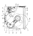
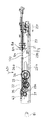
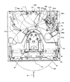
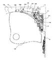
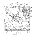
図1は本発明の第1の実施の形態のディスクローディング装置の上面図であり、図2は同分解斜視図である。図3から図6は規格直径が12cmのディスク(以下、大径のディスク100という)を、このディスクローディング装置に装着するときの動作を示す上面図である。図7Aから図9Aは大径のディスク100を装着するときの、トリガーレバー9の動きを示す一部の上面図である。図10から図13は、規格直径が8cmのディスク(以下、小径のディスク120という)を装着するときの動作を示すディスクローディング装置の上面図である。図14Aから図15Aは、小径のディスク120を装着するときのトリガーレバー9の動作を示す一部の上面図、及び図16から図18は図13の右側面図である。
(First embodiment)
A disk loading apparatus according to a first embodiment of the present invention will be described with reference to FIGS.
FIG. 1 is a top view of a disk loading apparatus according to a first embodiment of the present invention, and FIG. 2 is an exploded perspective view thereof. 3 to 6 are top views showing the operation when a disc having a standard diameter of 12 cm (hereinafter referred to as a large-diameter disc 100) is mounted on this disc loading apparatus. 7A to 9A are partial top views showing the movement of the trigger lever 9 when the large-diameter disk 100 is mounted. FIGS. 10 to 13 are top views of the disk loading apparatus showing the operation when a disk having a standard diameter of 8 cm (hereinafter referred to as a small diameter disk 120) is loaded. 14A to 15A are partial top views showing the operation of the trigger lever 9 when the small-diameter disk 120 is mounted, and FIGS. 16 to 18 are right-side views of FIG.

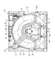
図1及び図2において、本第1の実施の形態のディスクローディング装置は、最下部の支持基板15と最上部のサブシャーシ1で形成される筐体内に、図2に示す各部品が取り付けられている。すなわち、支持基板15は、図2に示す各部品を支持している。支持基板15は、中央部にトラバース取付孔16を有している。トラバース取付孔16にはターンテーブル47a及び光ピックアップ47bを有するトラバース47が3つの取付けねじ48a、48b、48cで取り付けられる。   1 and 2, in the disk loading apparatus according to the first embodiment, the components shown in FIG. 2 are mounted in a casing formed by the lowermost support substrate 15 and the uppermost subchassis 1. ing. That is, the support substrate 15 supports each component shown in FIG. The support substrate 15 has a traverse mounting hole 16 in the center. A traverse 47 having a turntable 47a and an optical pickup 47b is attached to the traverse attachment hole 16 with three attachment screws 48a, 48b and 48c.

サブシャーシ1には扇形の開口部2a、2bが設けられており、後で説明するように、ディスクローディング装置に大径のディスク100又は小径のディスク120を装着したとき、各ディスクの上面(例えばラベル面)が開口部2a、2bから見えるようになっている。ディスクローディング装置内に装着された大径のディスク100が占める領域を「大径ディスク装着領域1d」ということにし、小径のディスク120が占める領域を「小径ディスク装着領域1e」ということにし、これらの領域を図1に2点鎖線で示す。   The sub-chassis 1 is provided with fan-shaped openings 2a and 2b. As will be described later, when the large-diameter disk 100 or the small-diameter disk 120 is mounted on the disk loading device, the upper surface of each disk (for example, The label surface is visible from the openings 2a and 2b. The area occupied by the large-diameter disk 100 mounted in the disk loading apparatus is referred to as “large-diameter disk mounting area 1d”, and the area occupied by the small-diameter disk 120 is referred to as “small-diameter disk mounting area 1e”. The region is indicated by a two-dot chain line in FIG.

ディスクローディング装置のディスク挿入口5の近傍には、ローラ軸36によって保持されるゴムローラ38が設けられている。ローラ軸36は、ローラレバー39の両端部に取り付けられた左軸受40と右軸受41により回転可能に支持されている。ローラ軸36の、図2において右端にはローラ歯車37が取り付けられている。ローラ歯車37は、中継ギアA35、ウオームホイールA32、ウオームギア31、回動軸29、ウオームホイールB30、ウオームプーリ27、及びベルト26を経てモータ24に連結されている。通常はモータ24が回転すると、ローラ軸36及びそれに嵌められたゴムローラ38が回転する。   A rubber roller 38 held by a roller shaft 36 is provided in the vicinity of the disk insertion slot 5 of the disk loading device. The roller shaft 36 is rotatably supported by a left bearing 40 and a right bearing 41 attached to both ends of the roller lever 39. A roller gear 37 is attached to the right end of the roller shaft 36 in FIG. The roller gear 37 is connected to the motor 24 via a relay gear A35, a worm wheel A32, a worm gear 31, a rotating shaft 29, a worm wheel B30, a worm pulley 27, and a belt 26. Normally, when the motor 24 rotates, the roller shaft 36 and the rubber roller 38 fitted thereto rotate.

ローラレバー39は両端部の軸受孔39a、39bで回転可能に支持基板15に取り付けられている。また、軸受孔39a、39bと回転中心軸を共通にしたクランプレバー43が回動可能に取り付けられている。クランプレバー43には、ゴムローラ38と対向する位置にガイドロッド44が取り付けられ、クランパー46側には押え板ばね45が取り付けられている。押え板ばね45には、ディスク100を回転可能に保持するクランパー46が回転可能に取り付けられている。   The roller lever 39 is rotatably attached to the support substrate 15 through bearing holes 39a and 39b at both ends. A clamp lever 43 having a common rotation center axis with the bearing holes 39a and 39b is rotatably attached. A guide rod 44 is attached to the clamp lever 43 at a position facing the rubber roller 38, and a presser plate spring 45 is attached to the clamper 46 side. A clamper 46 that rotatably holds the disc 100 is rotatably attached to the presser leaf spring 45.

図2において、サブシャーシ1の下方に図示されている、第2の検知レバーの一例であるトリガーレバー9、第1の検知レバーの一例であるディスク検知レバー12は、挿入口5から矢印5aの方向に挿入されるディスク100又は120の外周に当接して、ディスク100又は120が装置内に挿入されたことを検知するレバー群である。また、第2の位置決めレバーの一例である右センタリングレバー8、第1の位置決めレバーの一例である左センタリングレバー11は、挿入口5から矢印5aの方向に挿入されるディスク120の外周に当接して、ディスク100を、ディスク装着位置に位置決めするためのレバー群である。   In FIG. 2, a trigger lever 9, which is an example of a second detection lever, and a disk detection lever 12, which is an example of a first detection lever, illustrated below the subchassis 1 are indicated by an arrow 5 a from the insertion port 5. It is a lever group that contacts the outer periphery of the disk 100 or 120 inserted in the direction and detects that the disk 100 or 120 is inserted into the apparatus. The right centering lever 8 as an example of the second positioning lever and the left centering lever 11 as an example of the first positioning lever abut on the outer periphery of the disk 120 inserted from the insertion port 5 in the direction of the arrow 5a. And a lever group for positioning the disk 100 at the disk mounting position.

本第1の実施の形態のディスクローディング装置では、後で詳しく説明するように、これらのレバー群が、図1に示す第1の基板の一例であるサブシャーシ1の、左上コーナー部1a及び右上コーナー部1bの大径ディスク装着領域1dの外部に取付けられている。本実施の形態では、ディスク100を装着したとき、前記レバー群がすべてディスク100の外周から外側の領域、すなわち大径ディスク装着領域1dの外部にあり、大径ディスク装着領域1dの内部には存在しないことが特徴である。なお、これらのレバー群は第2の基板の一例である前記支持基板15に取り付けて構成してもよい。   In the disk loading apparatus according to the first embodiment, as will be described in detail later, these lever groups are provided in the upper left corner 1a and the upper right of the sub chassis 1 which is an example of the first board shown in FIG. It is attached to the outside of the large-diameter disk mounting area 1d of the corner portion 1b. In the present embodiment, when the disk 100 is loaded, the lever groups are all located outside the outer periphery of the disk 100, that is, outside the large-diameter disk loading area 1d, and are present inside the large-diameter disk loading area 1d. The feature is not to. In addition, you may comprise these lever groups attached to the said support substrate 15 which is an example of a 2nd board | substrate.

図3において、右センタリングレバー8は支点8cでサブシャーシ1に回動可能に取り付けられている。トリガーレバー9は、支点9cで右センタリングレバー8に設けられた軸8dに回動可能に取り付けられている。左センタリングレバー11は支点11cでサブシャーシ1に回動可能に取り付けられている。検知レバー12は支点12cで左センタリングレバー11に回動可能に取り付けられている。ここで、センタリングレバー8、11は、それぞれ後述するように連結されて、挿入時におけるディスク120の位置決めを行う、第1、第2の位置決めレバーとしての機能を有している。   In FIG. 3, the right centering lever 8 is rotatably attached to the subchassis 1 at a fulcrum 8c. The trigger lever 9 is rotatably attached to a shaft 8d provided on the right centering lever 8 at a fulcrum 9c. The left centering lever 11 is rotatably attached to the subchassis 1 at a fulcrum 11c. The detection lever 12 is rotatably attached to the left centering lever 11 at a fulcrum 12c. Here, the centering levers 8 and 11 are connected as will be described later, and have functions as first and second positioning levers for positioning the disk 120 at the time of insertion.

図2から図9A及びBを参照して、本第1の実施の形態のディスクローディング装置に規格直径12cmの大径のディスク100を装着するときの動作について説明する。図3から図6はディスク100の装着動作に関連のある要素のみを図示したディスクローディング装置の上面図である。   With reference to FIG. 2 to FIG. 9A and FIG. 9B, an operation when a large-diameter disk 100 having a standard diameter of 12 cm is mounted on the disk loading apparatus of the first embodiment will be described. 3 to 6 are top views of the disk loading apparatus illustrating only elements related to the loading operation of the disk 100. FIG.

図3はディスク100を挿入する前の状態を示す。トリガーレバー9は、支持基板15に形成された凹みである右ストッパー19に、トリガーレバー9の支点9cの近くに設けたカムピン9dが対向した状態にあり、先端に設けた係合ピンの一例であるディスク係合ピン9aが大径ディスク装着領域1dの中央部近く(小径ディスク装着領域1eの内部(図1))まで入り込んでいる。ディスク検知レバー12は、支持基板15に形成された左ストッパー18に、ディスク検知レバー12の支点12c近くに設けたカムピン12bが対向した状態にあり、先端に設けた検知ピンの一例であるディスク検知ピン12aが大径ディスク装着領域1dの左側部分に少し入っている。左センタリングレバー11の位置決めピンの一例であるディスク位置決めピン11aを有する部分は大径ディスク装着領域1dの左側部分に少し入り込んでいる。右センタリングレバー8のディスク位置決めピン8aを有する部分は大径ディスク装着領域1dの右側部分に少し入り込んでいる。右センタリングレバー8のディスク位置決めピン8aと左センタリングレバー11のディスク位置決めピン11aとは、図3に示すように、ディスク挿入方向5aに大径ディスク装着領域1dの中心1fを通る線1gに対して線対称に配置されるとともに、中心1fを通り且つ線1gと直交する線1hよりもディスク挿入方向下流側に配置されている。なお、図3に示すような、ディスクが挿入される前のトリガーレバー9、ディスク検知レバー12の位置を、「初期位置」という。   FIG. 3 shows a state before the disc 100 is inserted. The trigger lever 9 is an example of an engagement pin provided at the tip, in which the cam pin 9d provided near the fulcrum 9c of the trigger lever 9 is opposed to the right stopper 19 which is a recess formed in the support substrate 15. A certain disk engaging pin 9a enters near the center of the large-diameter disk mounting area 1d (inside the small-diameter disk mounting area 1e (FIG. 1)). The disc detection lever 12 is in a state in which a cam pin 12b provided near the fulcrum 12c of the disc detection lever 12 faces a left stopper 18 formed on the support substrate 15, and is a disc detection which is an example of a detection pin provided at the tip. The pin 12a is slightly inserted in the left part of the large-diameter disk mounting area 1d. A portion having a disc positioning pin 11a, which is an example of a positioning pin of the left centering lever 11, slightly enters the left portion of the large-diameter disc mounting area 1d. The portion of the right centering lever 8 having the disc positioning pin 8a slightly enters the right portion of the large-diameter disc mounting area 1d. As shown in FIG. 3, the disc positioning pin 8a of the right centering lever 8 and the disc positioning pin 11a of the left centering lever 11 are arranged with respect to a line 1g passing through the center 1f of the large-diameter disc mounting area 1d in the disc insertion direction 5a. They are arranged symmetrically with respect to the line, and are arranged downstream of the line 1h passing through the center 1f and perpendicular to the line 1g in the disc insertion direction. The positions of the trigger lever 9 and the disk detection lever 12 before the disk is inserted as shown in FIG. 3 are referred to as “initial position”.

トリガーレバー9は付勢ばね10により支点9cを中心に反時計方向に付勢されており、ディスク検知レバー12はディスク検知レバーばね13により、支点12cを中心に反時計方向に付勢されている。左センタリングレバー11はセンタリングレバーばね14により、支点孔11cを中心に反時計方向に付勢されている。これらのばね10、13、14によって、ディスク検知ピン12a、ディスク位置決めピン11aは大径ディスク装着領域1dの内部に、ディスク係合ピン9aは小径ディスク装着領域1eの内部に入り込んだ状態で安定して保持されている。なお、右センタリングレバー8は、ディスク位置決めピン8aの反対側の端部に設けた係合ピン8bで左センタリングレバー11の係合孔11bに連結されている。そのため、右センタリングレバー8は、左センタリングレバー11を反時計方向に付勢しているセンタリングレバーばね14により、支点8cを中心に時計方向に付勢されている。この付勢により、ディスク位置決めピン8aは大径ディスク装着領域1dの内部に入り込んだ状態で安定して保持されている。   The trigger lever 9 is urged counterclockwise around the fulcrum 9c by the urging spring 10, and the disc detection lever 12 is urged counterclockwise around the fulcrum 12c by the disc detection lever spring 13. . The left centering lever 11 is biased counterclockwise by a centering lever spring 14 around the fulcrum hole 11c. By these springs 10, 13, and 14, the disk detection pin 12a and the disk positioning pin 11a are stabilized inside the large-diameter disk mounting area 1d, and the disk engaging pin 9a is stabilized inside the small-diameter disk mounting area 1e. Is held. The right centering lever 8 is connected to the engagement hole 11b of the left centering lever 11 by an engagement pin 8b provided at the end opposite to the disk positioning pin 8a. Therefore, the right centering lever 8 is urged clockwise around the fulcrum 8c by the centering lever spring 14 that urges the left centering lever 11 counterclockwise. By this urging, the disk positioning pin 8a is stably held in a state of entering the inside of the large-diameter disk mounting area 1d.

ディスク100を図2及び図3に示す挿入口5から矢印5aの方向へ挿入すると、ディスク100がゴムローラ38に接する手前で、挿入口5の中央近傍に設けられたスイッチ50が駆動されて閉となる。スイッチ50は、例えば光センサで構成されている。スイッチ50の閉によりモータ24に通電されてモータ24が回転し、モータ24の回転によりゴムローラ38が回転する。さらにディスク100は、装置内部挿入されると、回転しているゴムローラ38と、クランプレバー43に固定されたガイドロッド44との間に挟まれ、図3の矢印5aの方向に駆動される。   When the disc 100 is inserted in the direction of the arrow 5a from the insertion port 5 shown in FIGS. 2 and 3, the switch 50 provided near the center of the insertion port 5 is driven and closed before the disc 100 comes into contact with the rubber roller 38. Become. The switch 50 is composed of, for example, an optical sensor. When the switch 50 is closed, the motor 24 is energized to rotate the motor 24, and the rotation of the motor 24 rotates the rubber roller 38. Further, when the disc 100 is inserted into the apparatus, the disc 100 is sandwiched between the rotating rubber roller 38 and the guide rod 44 fixed to the clamp lever 43, and is driven in the direction of the arrow 5a in FIG.

ゴムローラ38の駆動によって移動するディスク100は、トリガーレバー9のディスク係合ピン9a及びディスク検知レバー12のディスク検知ピン12aに、ディスク100の外周が当接した後、更に矢印5a方向に移動する。ディスク100の外周がディスク位置決めピン8a及び11aに当接した時点の状態を図4に示す。   The disc 100 that is moved by driving the rubber roller 38 further moves in the direction of the arrow 5a after the outer periphery of the disc 100 abuts on the disc engagement pin 9a of the trigger lever 9 and the disc detection pin 12a of the disc detection lever 12. FIG. 4 shows a state when the outer periphery of the disk 100 contacts the disk positioning pins 8a and 11a.

図3の状態から図4の状態に移行する過程で、ディスク100に押されたディスク検知レバー12のディスク検知ピン12aは支点12cの回りを矢印12rで示す方向(時計方向)に回動する。ディスク検知レバー12の矢印12r方向への回動により、ディスク検知レバー12の支点12c近くのカムピン12bも同様に矢印12r方向に回動し、左ストッパー18から離脱する。これにより、左センタリングレバー11のロック状態が解除される。図4では、その離脱した状態を示している。ディスク検知レバー12は、カムピン12bが、支持基板15の溝カム15dに対向状態となることにより、さらに矢印12r方向に回動可能となる。すなわちディスク検知レバー12は左センタリングレバー11と共に更に回動可能な状態になっている。   In the process of shifting from the state of FIG. 3 to the state of FIG. 4, the disk detection pin 12a of the disk detection lever 12 pushed by the disk 100 rotates around the fulcrum 12c in the direction indicated by the arrow 12r (clockwise). As the disc detection lever 12 rotates in the direction of the arrow 12r, the cam pin 12b near the fulcrum 12c of the disc detection lever 12 similarly rotates in the direction of the arrow 12r and is detached from the left stopper 18. Thereby, the locked state of the left centering lever 11 is released. FIG. 4 shows the detached state. The disc detection lever 12 can be further rotated in the direction of the arrow 12r when the cam pin 12b is opposed to the groove cam 15d of the support substrate 15. That is, the disc detection lever 12 is further rotatable together with the left centering lever 11.

また、図3の状態から図4の状態に移行する過程で、トリガーレバー9は、ディスク係合ピン9aがディスク100の外周に押されて支点9cの回りを矢印9rで示す方向(時計方向)に回動し、カムピン9dが右ストッパー19から離脱する。これにより、右センタリングレバー8のロック状態が解除される。そのため、トリガーレバー9は右センタリングレバー8と共に、更に回動可能な状態になる。   In the process of shifting from the state shown in FIG. 3 to the state shown in FIG. 4, the trigger lever 9 moves in the direction indicated by the arrow 9r (clockwise) around the fulcrum 9c when the disk engaging pin 9a is pushed on the outer periphery of the disk 100. The cam pin 9d is detached from the right stopper 19. Thereby, the locked state of the right centering lever 8 is released. For this reason, the trigger lever 9 is further rotatable together with the right centering lever 8.

ディスク100が更に矢印5a方向に移動することにより、ディスク位置決めピン8a、11a、ディスク係合ピン9a、ディスク検知ピン12aは、それぞれディスク100の外周方向に押され、大径ディスク装着領域1dの外部に出て、図5に示す状態になる。この状態でディスク100は支持基板15の壁15aに当接して移動を停止し、ディスク装着位置に位置決めされる。このとき、ローラ軸36はモータ24により回転しているが、ローラ軸36とゴムローラ38との間は一定の摩擦力で伝達しているため、ディスク100とゴムローラ38との間の摩擦力が大きくなることにより、ディスク100の記録面に接しているゴムローラ38は回転せず、ローラ軸36とゴムローラ38間がすべり回転する状態となる。   As the disk 100 further moves in the direction of the arrow 5a, the disk positioning pins 8a and 11a, the disk engagement pin 9a, and the disk detection pin 12a are respectively pushed toward the outer periphery of the disk 100, so that the outside of the large diameter disk mounting area 1d To the state shown in FIG. In this state, the disk 100 comes into contact with the wall 15a of the support substrate 15 and stops moving, and is positioned at the disk mounting position. At this time, the roller shaft 36 is rotated by the motor 24. However, since the roller shaft 36 and the rubber roller 38 are transmitted with a constant frictional force, the frictional force between the disk 100 and the rubber roller 38 is large. As a result, the rubber roller 38 in contact with the recording surface of the disk 100 does not rotate, and the roller shaft 36 and the rubber roller 38 slide and rotate.

また、後で詳しく説明するように、図2に示されているクランパー46を、トラバース47のターンテーブル47aの方向に移動させると共に、ゴムローラ38を下方に退避させることにより、ターンテーブル47aがディスク100の中央孔に入り込んで、ディスク100が装着される。この後、ディスク位置決めピン8a、11a、ディスク係合ピン9a、ディスク検知ピン12aは、後述する動作により、ディスク100の外周より離れるようになっており、その離れた状態を図6に示す。この状態で、後述するスイッチ51が駆動されて、モータ24は停止し、ディスク100の装着が完了する。   Further, as will be described in detail later, by moving the clamper 46 shown in FIG. 2 in the direction of the turntable 47a of the traverse 47 and by retracting the rubber roller 38 downward, the turntable 47a is moved to the disc 100. The disc 100 is loaded in the central hole. Thereafter, the disk positioning pins 8a and 11a, the disk engagement pin 9a, and the disk detection pin 12a are separated from the outer periphery of the disk 100 by the operation described later, and the separated state is shown in FIG. In this state, a switch 51 described later is driven, the motor 24 is stopped, and the mounting of the disk 100 is completed.

トリガーレバー9の動作を図7A及びBから図9A及びBを参照して詳細に説明する。図7Aはディスク100を挿入する前のトリガーレバー9の位置を示し、この位置は図3と同じである。図7A及びBから図9A及びBにはトリガーレバー9、トリガーロッド21及びカムロッド23が図示されており、これらの相互間の位置関係は、図2の分解斜視図に示されている。トリガーレバー9は、付勢ばね10(図3)により支点9cを回動中心として反時計方向に付勢されている。   The operation of the trigger lever 9 will be described in detail with reference to FIGS. 7A and 7B to FIGS. 9A and 9B. FIG. 7A shows the position of the trigger lever 9 before the disc 100 is inserted, and this position is the same as FIG. FIGS. 7A and B to FIGS. 9A and B show the trigger lever 9, the trigger rod 21 and the cam rod 23, and the positional relationship between them is shown in the exploded perspective view of FIG. The trigger lever 9 is urged counterclockwise by the urging spring 10 (FIG. 3) with the fulcrum 9c as the center of rotation.

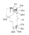
図3と同じ状態を示す図7Aの状態では、トリガーレバー9の右端にある駆動ピン9bは、トリガーロッド21に設けられている第1の溝カム21cに入っている。トリガーロッド21は、図7Bに示すように、支持基板15(図2)に設けたガイド孔20a、20bに嵌合されているトリガーロッド21のガイドピン21a、21bのうち、一方のガイドピン21aに作用する付勢ばね22により図7Aの上方に付勢された状態となっている。ガイド孔20a、20bは、カムロッド23の移動方向(図7A中の上下方向)に対して、傾斜する傾斜ガイド部20cと、図7A中の左右方向のガイド部20dとを有している。図7Bではガイドピン21a、21bが傾斜ガイド部20cの上端に、付勢ばね22により付勢されて保持された状態となっている。   In the state of FIG. 7A showing the same state as FIG. 3, the drive pin 9 b at the right end of the trigger lever 9 is in a first groove cam 21 c provided on the trigger rod 21. As shown in FIG. 7B, the trigger rod 21 is one of the guide pins 21a, 21b of the trigger rod 21 fitted in the guide holes 20a, 20b provided in the support substrate 15 (FIG. 2). It is in a state of being biased upward in FIG. The guide holes 20a and 20b have an inclined guide portion 20c that is inclined with respect to the moving direction of the cam rod 23 (vertical direction in FIG. 7A) and a guide portion 20d in the left-right direction in FIG. 7A. In FIG. 7B, the guide pins 21a and 21b are held at the upper end of the inclined guide portion 20c by being biased by the biasing spring 22.

図7Aの状態から、トリガーレバー9と右センタリングレバー8が、挿入されるディスク100の外周に押されて矢印9rの方向に回動すると、ディスク100がディスク位置決めピン8a、11aに当接する位置まで移動し、図4に示す状態となる。図4の状態では、トリガーレバー9のカムピン9dが右ストッパー19から離脱し、トリガーレバー9は右センタリングレバー8と共に、更に回動可能となっている。このため、トリガーレバー9は、さらにディスク100に押されて、支点9cを中心として矢印9rの方向に回動する。またディスク100にディスク位置決めピン8aが押されて支点8cを中心に反時計方向に回動する右センタリングレバー8の軸8dに嵌合されているトリガーレバー9の支点9cが、右センタリングレバー8の回動に伴って矢印8r方向に移動する。このトリガーレバー9の回動と支点9cの移動によって、トリガーレバー9の駆動ピン9bが溝カム21cから溝カム21eに移動する。   From the state of FIG. 7A, when the trigger lever 9 and the right centering lever 8 are pushed by the outer periphery of the inserted disc 100 and rotated in the direction of the arrow 9r, the disc 100 reaches a position where it abuts against the disc positioning pins 8a and 11a. It moves and it will be in the state shown in FIG. In the state of FIG. 4, the cam pin 9 d of the trigger lever 9 is detached from the right stopper 19, and the trigger lever 9 can be further rotated together with the right centering lever 8. Therefore, the trigger lever 9 is further pushed by the disc 100 and rotates in the direction of the arrow 9r about the fulcrum 9c. Further, the fulcrum 9c of the trigger lever 9 fitted to the shaft 8d of the right centering lever 8 that rotates counterclockwise around the fulcrum 8c when the disc positioning pin 8a is pushed onto the disc 100 is the right centering lever 8 As it rotates, it moves in the direction of the arrow 8r. By the rotation of the trigger lever 9 and the movement of the fulcrum 9c, the drive pin 9b of the trigger lever 9 moves from the groove cam 21c to the groove cam 21e.

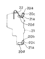
上記の移動をした状態を図8Aに示す。この移動により、ガイドピン21a、21bは、図8Bに示すように、付勢ばね22の付勢力に抗してガイド孔20a、20bの傾斜ガイド部20cの上端から下端に移動し、そのためトリガーロッド21は下方に動くこととなる。図8Aは、図5の状態と同じであり、ディスク100がディスク装着位置に到達した状態を示すものである。   FIG. 8A shows the state of the above movement. By this movement, the guide pins 21a and 21b move from the upper end to the lower end of the inclined guide portion 20c of the guide holes 20a and 20b against the urging force of the urging spring 22, as shown in FIG. 21 will move downward. FIG. 8A is the same as the state of FIG. 5 and shows a state where the disk 100 has reached the disk mounting position.

図7Aの状態から図8Aの状態への変化によるトリガーロッド21の図7A及び図8Aの下方への移動を「初期移動」という。初期移動により、トリガーロッド21の端面21jがカムロッド23のピン23bに係合してこれを押す。カムロッド23の初期移動前は、図16に示すように、カムロッド23に設けたラック23mが駆動小歯車34aと噛合していない状態にあるが、初期移動により図17に示すようにラック23mが駆動小歯車34aと噛合する位置まで移動する。このトリガーロッド21の初期移動後の、トリガーレバー9及びディスク検知レバー12の位置を、「トリガー位置」という。歯車列34、34a、33、32、35はモータ24により回転しているので、カムロッド23はラック23mを介して、モータ24により駆動されて矢印23rで示す方向、つまりディスクの挿入方向5aと逆方向に移動を開始する。カムロッド23の矢印23rの方向への移動により、モータ24、ベルト26、ウォームプーリ27、ウォームホイールB30、回動軸29、ウォームギア31、ウォームホイールA32、中継ギア35、ローラ歯車37、ローラ軸36、ゴムローラ38、及び傾斜穴部23nを有する駆動機構が、後述するように、図2に示すクランプレバー43を図17、図18に示す矢印43r方向に回動させる。これによりクランパー46が下降して、トラバース47のターンテーブル47a(図2)がディスク100の中央孔に入り込み、ディスク100が装着される。   The downward movement of the trigger rod 21 in FIGS. 7A and 8A due to the change from the state of FIG. 7A to the state of FIG. 8A is referred to as “initial movement”. By the initial movement, the end surface 21j of the trigger rod 21 engages with the pin 23b of the cam rod 23 and pushes it. Before the initial movement of the cam rod 23, as shown in FIG. 16, the rack 23m provided on the cam rod 23 is not in mesh with the drive small gear 34a, but the rack 23m is driven by the initial movement as shown in FIG. It moves to the position that meshes with the small gear 34a. The positions of the trigger lever 9 and the disc detection lever 12 after the initial movement of the trigger rod 21 are referred to as “trigger positions”. Since the gear trains 34, 34a, 33, 32, and 35 are rotated by the motor 24, the cam rod 23 is driven by the motor 24 via the rack 23m and is opposite to the direction indicated by the arrow 23r, that is, the disc insertion direction 5a. Start moving in the direction. As the cam rod 23 moves in the direction of the arrow 23r, the motor 24, belt 26, worm pulley 27, worm wheel B30, rotating shaft 29, worm gear 31, worm wheel A32, relay gear 35, roller gear 37, roller shaft 36, As will be described later, the drive mechanism having the rubber roller 38 and the inclined hole 23n rotates the clamp lever 43 shown in FIG. 2 in the direction of the arrow 43r shown in FIGS. As a result, the clamper 46 is lowered, the turntable 47a (FIG. 2) of the traverse 47 enters the central hole of the disc 100, and the disc 100 is mounted.

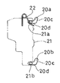
また、モータ24の駆動により、図8Aに示す状態から、カムロッド23が矢印23rの方向へ移動すると、トリガーロッド21のピン21fの嵌合状態は、図8Aから図9Aに示す状態に変化し、カムの一例である溝カム23aの傾斜部23dに案内されて最上部23eに到達する。この移動の過程で、傾斜部23dにおいてピン21fが図8A及び図9Aの左方に押されるので、トリガーロッド21は矢印21rの方向へ移動する。ここで、図8Aから図9Aへの状態変化により、ガイドピン21a、21bは、図9Bに示すように、ガイド孔20a、20bのガイド部20dにガイドされて、図8A及び図9Aの左方に移動することとなる。そのため、トリガーロッド21の図8A及び図9A中の上部斜辺によって形成されたカム21gが右センタリングレバー8の軸8dを上方に押上げる。その結果、右センタリングレバー8は支点8cを回動中心として反時計方向に回動し、トリガーレバー9は溝カム21eに嵌合された駆動ピン9bを中心として時計方向に回動するため、先端のディスク係合ピン9aはディスク100の外周から離れた状態になる(図9A及び図6)。   When the cam rod 23 moves in the direction of the arrow 23r from the state shown in FIG. 8A by driving the motor 24, the fitting state of the pin 21f of the trigger rod 21 changes from the state shown in FIG. 8A to the state shown in FIG. 9A. Guided by the inclined portion 23d of the groove cam 23a, which is an example of the cam, reaches the uppermost portion 23e. In the course of this movement, the pin 21f is pushed to the left in FIGS. 8A and 9A at the inclined portion 23d, so that the trigger rod 21 moves in the direction of the arrow 21r. Here, due to the state change from FIG. 8A to FIG. 9A, as shown in FIG. 9B, the guide pins 21a and 21b are guided by the guide portions 20d of the guide holes 20a and 20b to the left of FIG. 8A and FIG. 9A. Will be moved to. Therefore, the cam 21g formed by the upper oblique side of the trigger rod 21 in FIGS. 8A and 9A pushes up the shaft 8d of the right centering lever 8 upward. As a result, the right centering lever 8 rotates counterclockwise about the fulcrum 8c, and the trigger lever 9 rotates clockwise about the drive pin 9b fitted to the groove cam 21e. The disc engaging pin 9a is separated from the outer periphery of the disc 100 (FIGS. 9A and 6).

又図6に示すように、右センタリングレバー8が支点8cを回動中心として反時計方向に回動すると、係合ピン8bで右センタリングレバー8に連結されている左センタリングレバー11は、支点11cを回動中心として時計方向に回動する。これにより、ディスク位置決めピン8a及び11aもディスク100の外周から離れた状態になる。また検知レバー12も時計方向に回動してディスク検知ピン12aがディスクの外周から離れた状態になる。このトリガーレバー9及びディスク検知レバー12がディスクの外周から離れて退避する位置、つまり大径ディスク装着領域1dの外部に退避する位置を、「退避位置」という。以上の動作の完了により大径のディスク100の装着が完了することになる。この過程において、前述のカムロッド23が矢印23rの方向に移動することにより、図16〜図18に示すように、カムロッド23に対向するスイッチ51が図18に示す状態において駆動され、モータ24が停止する。   As shown in FIG. 6, when the right centering lever 8 rotates counterclockwise around the fulcrum 8c, the left centering lever 11 connected to the right centering lever 8 by the engaging pin 8b becomes the fulcrum 11c. Rotate clockwise around the center of rotation. As a result, the disk positioning pins 8 a and 11 a are also separated from the outer periphery of the disk 100. The detection lever 12 is also rotated in the clockwise direction so that the disk detection pin 12a is separated from the outer periphery of the disk. A position where the trigger lever 9 and the disk detection lever 12 are retracted away from the outer periphery of the disk, that is, a position where the trigger lever 9 and the disk detection lever 12 are retracted outside the large-diameter disk mounting area 1d is referred to as a “retraction position”. When the above operation is completed, the mounting of the large-diameter disk 100 is completed. In this process, when the cam rod 23 moves in the direction of the arrow 23r, the switch 51 facing the cam rod 23 is driven in the state shown in FIG. 18 as shown in FIGS. To do.

なお、本実施の形態においては、ラック23m、歯車列34a、34、33、32、ウォームギア31、回動軸29、ウォームホイールB30、ウォームプーリ27、ベルト26、及びモータ24により駆動装置(カムロッド駆動装置)を構成している。しかしながら、本発明は上記の構成に限定されるものではなく、初期移動後のカムロッド23に駆動力を与えて、トリガーレバー9のディスク係合ピン9aがディスク100の外周から離れるようにするために、カムロッド23を移動させるような構成であればよい。
また、駆動機構においても、上記構成に限定されるものではなく、ディスクを挿入完了後に下降させて、ディスク装着位置にディスクを装着できるような構成であればよい。
In the present embodiment, the rack 23m, the gear trains 34a, 34, 33, 32, the worm gear 31, the rotating shaft 29, the worm wheel B30, the worm pulley 27, the belt 26, and the motor 24 are used as a drive device (cam rod drive). Device). However, the present invention is not limited to the above-described configuration. In order to apply a driving force to the cam rod 23 after the initial movement so that the disk engaging pin 9a of the trigger lever 9 is separated from the outer periphery of the disk 100. Any configuration that moves the cam rod 23 may be used.
Also, the drive mechanism is not limited to the above configuration, and any configuration may be used as long as the disc can be lowered after the insertion is completed and the disc can be loaded at the disc loading position.

次に規格直径8cmの小径のディスク120をディスクローディング装置に装着するときの動作について、図10から図18を参照して説明する。ディスクローディング装置のディスク挿入口5の横幅は、大径のディスク100の直径より若干大きい寸法になされている。従ってこの横幅は小径のディスク120の直径よりも大幅に大きい。そのため、使用者がディスクローディング装置にディスク120を挿入するとき、ディスク120が挿入口5のどの部分に挿入されるかわからない。例えば、図10に示す例では、ディスク120を挿入口5の左側の部分に挿入している。また図11に示す例では、ディスク120を挿入口5の右側の部分に挿入している。
本実施の形態のディスクローディング装置では、ディスク120が挿入口5のどの位置から挿入されてもディスク120をディスク装着位置に位置決めすることができる。
Next, an operation when the small-diameter disk 120 having a standard diameter of 8 cm is mounted on the disk loading apparatus will be described with reference to FIGS. The width of the disc insertion slot 5 of the disc loading device is slightly larger than the diameter of the large-diameter disc 100. Therefore, this lateral width is significantly larger than the diameter of the small-diameter disk 120. Therefore, when the user inserts the disk 120 into the disk loading device, it is not known in which part of the insertion slot 5 the disk 120 is inserted. For example, in the example shown in FIG. 10, the disc 120 is inserted into the left portion of the insertion slot 5. In the example shown in FIG. 11, the disc 120 is inserted into the right portion of the insertion slot 5.
In the disk loading apparatus of the present embodiment, the disk 120 can be positioned at the disk mounting position regardless of the position of the insertion slot 5 where the disk 120 is inserted.

図10を参照して、挿入口5の左側の部分にディスク120を挿入した場合の動作を説明する。図10では、ディスク120が挿入された後、左センタリングレバー11のディスク位置決めピン11aに当接した状態を示す。
図10において、使用者がディスク120を挿入口5に挿入すると、ゴムローラ38に当接する手前で、前記大径のディスク100を挿入するときと同様に、スイッチ50(図1)が閉となり、モータ24が回転を開始する。モータ24の回転によりゴムローラ38が回転し、ディスク120を更に押し込むと回転しているゴムローラ38とクランプレバー43に固定されたガイドロッド44の間にディスク120が挟まれ、ディスク120は矢印5aの方向に搬送(挿入)されて、ディスクローディング装置内に入ってゆく。ディスク120は、まずディスク検知レバー12のディスク検知ピン12aに当たり、これを押すのでディスク検知レバー12は時計方向に少し回動し、カムピン12bが左ストッパー18から離脱する。次にディスク120は左センタリングレバー11のディスク位置決めピン11aに当たり、これを押す。ディスク位置決めピン11aは、ディスク120に押されて図10の時計方向に回動しようとするが、連結された右センタリングレバー8が、軸8dに回動可能に取り付けられたトリガーレバー9のカムピン9dと、支持基板15に形成された右ストッパー19との係合によりロックされているため、ディスク120はディスク位置決めピン11aに接しながら右方に移動しつつ更に挿入されてゆく。
With reference to FIG. 10, the operation when the disc 120 is inserted into the left portion of the insertion slot 5 will be described. FIG. 10 shows a state where the disc 120 is in contact with the disc positioning pin 11a of the left centering lever 11 after being inserted.
In FIG. 10, when the user inserts the disk 120 into the insertion slot 5, the switch 50 (FIG. 1) is closed just before the large-diameter disk 100 is inserted just before contacting the rubber roller 38, and the motor 24 starts to rotate. The rubber roller 38 is rotated by the rotation of the motor 24. When the disk 120 is further pushed in, the disk 120 is sandwiched between the rotating rubber roller 38 and the guide rod 44 fixed to the clamp lever 43, and the disk 120 is in the direction of the arrow 5a. Are transferred (inserted) into the disk loading device. The disk 120 first hits and pushes the disk detection pin 12a of the disk detection lever 12, so that the disk detection lever 12 is slightly rotated clockwise and the cam pin 12b is detached from the left stopper 18. Next, the disk 120 hits the disk positioning pin 11a of the left centering lever 11 and pushes it. The disk positioning pin 11a is pushed by the disk 120 and tries to rotate in the clockwise direction in FIG. 10, but the connected right centering lever 8 is a cam pin 9d of the trigger lever 9 that is rotatably attached to the shaft 8d. Since the disk 120 is locked by engagement with the right stopper 19 formed on the support substrate 15, the disk 120 is further inserted while moving to the right while contacting the disk positioning pin 11a.

そして、ディスク120はトリガーレバー9のディスク係合ピン9aに当たり、これを押して矢印9r方向に回動させる。これにより、カムピン9dは右ストッパー19から離脱し、右センタリングレバー8のロックが解除される。しかし、ディスク120の右方への移動に伴い、ディスク120とディスク検知レバー12のディスク検知ピン12aとの当たりが解除されるので、ディスク検知レバー12は検知レバーばね13の付勢力で反時計方向に回動して、カムピン12bは左ストッパー18と係合する状態に復帰する。このため、左センタリングレバー11がロックされ、ディスク位置決めピン11aは動かない。従って、ディスク120は動かないディスク位置決めピン8aに当たり進入が止まる。このときディスク120は左側のディスク位置決めピン11aにも当たっており、図12に示すように、ディスク120は2つのディスク位置決めピン8a、11aに当たることにより、ディスク装着位置に位置決めされる。   Then, the disk 120 hits the disk engaging pin 9a of the trigger lever 9, and pushes this to rotate in the arrow 9r direction. As a result, the cam pin 9d is detached from the right stopper 19, and the lock of the right centering lever 8 is released. However, as the disk 120 moves to the right, the contact between the disk 120 and the disk detection pin 12a of the disk detection lever 12 is released, so the disk detection lever 12 is counterclockwise by the urging force of the detection lever spring 13. And the cam pin 12b returns to the state of engaging with the left stopper 18. For this reason, the left centering lever 11 is locked and the disk positioning pin 11a does not move. Therefore, the disk 120 hits the disk positioning pin 8a which does not move, and stops entering. At this time, the disk 120 also hits the disk positioning pin 11a on the left side, and as shown in FIG. 12, the disk 120 is positioned at the disk mounting position by hitting the two disk positioning pins 8a and 11a.

次に、図11を参照して、ディスク120を挿入口5の右側部分から挿入した場合の動作を説明する。挿入されたディスク120は、まず右センタリングレバー8のディスク位置決めピン8aに当たる。ディスク位置決めピン8aはトリガーレバー9のカムピン9dが右ストッパー19に当たり動かない。そのため、ディスク120はディスク位置決めピン8aに接しつつ、図11の左上方に移動する。ディスク120はディスク係合ピン9aに当たるとこれを押しながら進み、トリガーレバー9は矢印9rの方向に回動するので、トリガーレバー9のカムピン9dが右ストッパー19から離脱する。しかし連結された左センタリングレバー11がロックされているため、図12に示すようにディスク120は左センタリングレバー11のディスク位置決めピン11aに当たって止まり、位置決めされる。すなわち、図10の状態で挿入した場合と同様にディスク120はディスク位置決めピン8a及び11aによって位置決めされる。   Next, with reference to FIG. 11, the operation when the disk 120 is inserted from the right side of the insertion slot 5 will be described. The inserted disc 120 first hits the disc positioning pin 8 a of the right centering lever 8. The disc positioning pin 8 a does not move when the cam pin 9 d of the trigger lever 9 hits the right stopper 19. Therefore, the disk 120 moves to the upper left in FIG. 11 while being in contact with the disk positioning pin 8a. When the disk 120 hits the disk engaging pin 9a, the disk 120 advances while pushing, and the trigger lever 9 rotates in the direction of the arrow 9r, so that the cam pin 9d of the trigger lever 9 is detached from the right stopper 19. However, since the connected left centering lever 11 is locked, the disk 120 hits the disk positioning pin 11a of the left centering lever 11 and is positioned as shown in FIG. That is, the disk 120 is positioned by the disk positioning pins 8a and 11a in the same manner as when inserted in the state of FIG.

前記の動作において、図10及び図11のいずれの場合でも、ディスク120がディスク位置決めピン8a及び11aに当たり、最終の位置決めがなされて図12の状態になる直前に、トリガーレバー9は矢印9r方向に回動する。このトリガーレバー9の動作について、図12から図15を参照して説明する。   10 and 11, in the above operation, the trigger lever 9 is moved in the direction of the arrow 9r immediately before the disk 120 hits the disk positioning pins 8a and 11a and the final positioning is performed to reach the state shown in FIG. Rotate. The operation of the trigger lever 9 will be described with reference to FIGS.

小径のディスク120が位置決めされて図12の状態になったとき、トリガーレバー9は図14Aに示す状態となっている。つまり、トリガーレバー9は初期位置からトリガー位置まで移動している。この状態は小径のディスク120の挿入前の状態である図7Aから変化した状態である。この図7Aから図14Aへの状態変化の過程で、トリガーレバー9の回動によって、トリガーレバー9の駆動ピン9bが図14Aに示すように溝カム21cから溝カム21hの入り口の壁21kに移動し、トリガーロッド21を矢印23rの方向に押す。この動作によって、図14Bに示すようにガイドピン21a、21bは、付勢ばね22の付勢力に抗してガイド孔20a、20bの傾斜ガイド部20cの上端から下端に移動する。これにより図14Aに示すように、トリガーロッド21の端面21jがカムロッド23のピン23bを矢印23r方向に押し、カムロッド23は図14Aの下方に初期移動する。その結果、前記の大径のディスク100の場合と同様に、初期移動前は図16に示すように、カムロッド23に設けたラック23mが駆動小歯車34aと噛合していない状態にあったものが、初期移動後、図17に示すように、カムロッド23のラック23mが駆動小歯車34aと噛合する。駆動小歯車34aはモータ24に駆動されているのでカムロッド23を更に矢印23r方向に移動させる。その結果、カムロッド23は、図14Aに示す状態から図15Aに示す状態へと変化し、ピン21fは溝カム23aの傾斜部23dに案内されて最上部23eに到達する。この移動の過程で、傾斜部23dによってピン21fが左方に押されるので、トリガーロッド21は矢印21r方向へ移動する。図14Aから図15Aへの状態変化により、ガイドピン21a、21bは、図15Bに示すように、ガイド孔20a、20bのガイド部20dにガイドされて図15Bの左方に移動する。この移動により、駆動ピン9bは溝カム21hの傾斜部に案内され、その傾斜面によって駆動ピン9cを支点として時計方向に回動するので、ディスク係合ピン9aは矢印9r方向に回動してトリガー位置から退避位置まで移動し、図15Aに示すようにディスク120の外周から離れる。図13の上面図にディスク係合ピン9aがディスク120の外周から離れた状態を示す。このとき、ディスク位置決めピン8a及び11aはディスク120の外周に当接している。   When the small-diameter disk 120 is positioned and enters the state shown in FIG. 12, the trigger lever 9 is in the state shown in FIG. 14A. That is, the trigger lever 9 has moved from the initial position to the trigger position. This state is a state changed from FIG. 7A which is a state before the small-diameter disk 120 is inserted. In the process of state change from FIG. 7A to FIG. 14A, as the trigger lever 9 rotates, the drive pin 9b of the trigger lever 9 moves from the groove cam 21c to the entrance wall 21k of the groove cam 21h as shown in FIG. 14A. Then, the trigger rod 21 is pushed in the direction of the arrow 23r. By this operation, the guide pins 21a and 21b move from the upper end to the lower end of the inclined guide portion 20c of the guide holes 20a and 20b against the urging force of the urging spring 22 as shown in FIG. 14B. As a result, as shown in FIG. 14A, the end surface 21j of the trigger rod 21 pushes the pin 23b of the cam rod 23 in the direction of the arrow 23r, and the cam rod 23 initially moves downward in FIG. 14A. As a result, as in the case of the large-diameter disk 100, the rack 23m provided on the cam rod 23 was not in mesh with the drive small gear 34a before the initial movement, as shown in FIG. After the initial movement, as shown in FIG. 17, the rack 23m of the cam rod 23 meshes with the drive small gear 34a. Since the driving small gear 34a is driven by the motor 24, the cam rod 23 is further moved in the direction of the arrow 23r. As a result, the cam rod 23 changes from the state shown in FIG. 14A to the state shown in FIG. 15A, and the pin 21f is guided by the inclined part 23d of the groove cam 23a and reaches the uppermost part 23e. In the course of this movement, the pin 21f is pushed to the left by the inclined portion 23d, so that the trigger rod 21 moves in the direction of the arrow 21r. 14A to 15A, the guide pins 21a and 21b are guided by the guide portions 20d of the guide holes 20a and 20b and move to the left in FIG. 15B, as shown in FIG. 15B. By this movement, the drive pin 9b is guided to the inclined portion of the groove cam 21h, and the inclined surface rotates about the drive pin 9c in the clockwise direction, so that the disk engaging pin 9a rotates in the direction of the arrow 9r. It moves from the trigger position to the retracted position and moves away from the outer periphery of the disk 120 as shown in FIG. 15A. The top view of FIG. 13 shows a state in which the disk engaging pin 9a is separated from the outer periphery of the disk 120. At this time, the disk positioning pins 8 a and 11 a are in contact with the outer periphery of the disk 120.

次にディスク120の外周からディスク位置決めピン8a及び11aが離れる動作について図16から図18を参照して説明する。
図16から図18は図13の右側面図である。図17に示すようにディスク位置決めピン8aは大径部8mと、大径部8mより直径の小さい小径部8nを有する。具体的寸法としては、例えば大径部8mの直径が3mm、小径部8nの直径が1mmである。図10から図13に示すようにディスク120を位置決めするときには、ディスク120の外周部は大径部8mに当接するように、ディスク120とディスク位置決めピン8a及び11aの高さが設定されている。
Next, the operation of separating the disk positioning pins 8a and 11a from the outer periphery of the disk 120 will be described with reference to FIGS.
16 to 18 are right side views of FIG. As shown in FIG. 17, the disk positioning pin 8a has a large diameter portion 8m and a small diameter portion 8n having a diameter smaller than that of the large diameter portion 8m. As specific dimensions, for example, the diameter of the large diameter portion 8m is 3 mm, and the diameter of the small diameter portion 8n is 1 mm. As shown in FIGS. 10 to 13, when the disk 120 is positioned, the height of the disk 120 and the disk positioning pins 8a and 11a is set so that the outer peripheral portion of the disk 120 contacts the large diameter portion 8m.

図12及び図13に示すディスク120の挿入動作中、図14Aに示す状態から図15Aに示す状態にカムロッド23が矢印23rの方向に初期移動する。カムロッド23が初期移動した結果、前記のように、移動前は図16に示すように、カムロッド23に設けたラック23mが駆動小歯車34aと噛合していない状態にあったものが、図17に示すように、カムロッド23のラック23mが駆動小歯車34aに噛み合う。歯車列34、34a、33、32、35は、ベルト26、ウォームプーリ27、ウォームホイールB30、回動軸29、及びウォームギア31を介してモータ24の駆動力により回転しているので、カムロッド23はラック23mを介してモータ24の駆動力を受け、更に矢印23rの方向に移動する。このカムロッド23の移動により、ローラ歯車37の軸36が、カムロッド23に設けられた傾斜穴部23nに案内されて、図18に示すように、下方に移動した状態になる。これに伴ってゴムローラ38を下方に退避させる。このとき、中継ギアA35とローラ歯車37との噛合が外れるので、ローラ歯車37が取り付けられたローラ軸36に保持されるゴムローラ38の回転が止まる。ローラ歯車37の下方への移動と同時に、カムロッド23の傾斜穴23pに案内されてクランプレバー43が軸43aを中心に矢印43rで示す方向に回動する。これにより、図2に全体の形状が示されているクランプレバー43に取り付けられた押え板ばね45は矢印45r(図18)で示す方向に動き、その下面に取り付けられているクランパー46がディスク120を矢印45rで示す方向に約3mm押下げる。その結果、ディスク120の中央の孔がターンテーブル47a(図2及び図3)に嵌め込まれる。ディスク120が押下げられた結果、ディスク120の内周は大径部8mから離れ、小径部8nにディスク120の内周面が触れないように隙間を保って対向する。以上の動作により、ディスク120の外周はディスク位置決めピン8a及び11aから離れ、回転可能な状態になる。   During the insertion operation of the disk 120 shown in FIGS. 12 and 13, the cam rod 23 is initially moved in the direction of the arrow 23r from the state shown in FIG. 14A to the state shown in FIG. 15A. As a result of the initial movement of the cam rod 23, as shown in FIG. 16, the rack 23m provided on the cam rod 23 was not engaged with the drive small gear 34a as shown in FIG. As shown, the rack 23m of the cam rod 23 meshes with the drive small gear 34a. Since the gear trains 34, 34 a, 33, 32, and 35 are rotated by the driving force of the motor 24 via the belt 26, the worm pulley 27, the worm wheel B 30, the rotating shaft 29, and the worm gear 31, the cam rod 23 is The driving force of the motor 24 is received through the rack 23m, and further the movement in the direction of the arrow 23r. By the movement of the cam rod 23, the shaft 36 of the roller gear 37 is guided to the inclined hole portion 23n provided in the cam rod 23 and is moved downward as shown in FIG. Along with this, the rubber roller 38 is retracted downward. At this time, since the meshing between the relay gear A35 and the roller gear 37 is released, the rotation of the rubber roller 38 held by the roller shaft 36 to which the roller gear 37 is attached is stopped. Simultaneously with the downward movement of the roller gear 37, the clamp lever 43 is rotated about the shaft 43a in the direction indicated by the arrow 43r while being guided by the inclined hole 23p of the cam rod 23. As a result, the presser leaf spring 45 attached to the clamp lever 43 whose overall shape is shown in FIG. 2 moves in the direction indicated by the arrow 45r (FIG. 18), and the clamper 46 attached to the lower surface of the presser leaf spring 45 Is pushed down by about 3 mm in the direction indicated by the arrow 45r. As a result, the central hole of the disk 120 is fitted into the turntable 47a (FIGS. 2 and 3). As a result of the disk 120 being pushed down, the inner periphery of the disk 120 is separated from the large diameter portion 8m and faces the small diameter portion 8n with a gap so that the inner peripheral surface of the disk 120 does not touch. By the above operation, the outer periphery of the disk 120 is separated from the disk positioning pins 8a and 11a and becomes rotatable.

なお、装着したディスク100又は120をディスクローディング装置から取り出す動作については説明を省略する。
本発明によれば、大径のディスク100をディスクローディング装置に装着したとき、ディスク100を位置決めするための、右センタリングレバー8、トリガーレバー9、左センタリングレバー11及びディスク検知レバー12を含むすべてのディスク位置決め機構要素が、ディスク100の装着領域1dの外部にあり、ディスク100の上面の上にはない。従って図1及び図2に示すサブシャーシ1の開口部2a、2bからディスク100の上面を見ることができる。
The description of the operation of taking out the loaded disc 100 or 120 from the disc loading device is omitted.
According to the present invention, when a large-diameter disk 100 is mounted on a disk loading device, all of the positions including the right centering lever 8, the trigger lever 9, the left centering lever 11, and the disk detection lever 12 for positioning the disk 100 are included. The disk positioning mechanism element is outside the mounting area 1 d of the disk 100 and is not on the upper surface of the disk 100. Therefore, the upper surface of the disk 100 can be seen from the openings 2a and 2b of the sub chassis 1 shown in FIGS.

小径のディスク120を装着したときは、右センタリングレバー8及び左センタリングレバー11が装着領域1dの内部にはあるが、小径のディスク120の外周から離れている。従ってディスク120の上面を前記の開口部2a、2bから見ることができる。ディスク100及び120の上面の上に、前記ディスク位置決め機構要素がないので、前記上面とサブシャーシ1との間の間隔を、回転中のディスク100又は120が接触しない程度に狭くすることができる。これによりディスクローディング装置の厚みを薄くすること(薄型化)が可能となる。   When the small-diameter disk 120 is mounted, the right centering lever 8 and the left centering lever 11 are inside the mounting area 1d, but are separated from the outer periphery of the small-diameter disk 120. Therefore, the upper surface of the disk 120 can be seen from the openings 2a and 2b. Since there is no disk positioning mechanism element on the upper surfaces of the disks 100 and 120, the distance between the upper surface and the subchassis 1 can be narrowed to such an extent that the rotating disks 100 or 120 do not contact each other. This makes it possible to reduce the thickness of the disk loading device (thinning).

(第2の実施の形態)
次に、本発明の第2の実施の形態のディスクローディング装置(ディスク駆動装置)を図19から図28を参照して説明する。
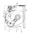
図19は第2の実施の形態のディスクローディング装置の分解斜視図であり、図20はディスクを挿入する前の待機状態を示す上面図である。図21は規格直径が12cmの大径のディスク100をこのディスクローディング装置に挿入するときの動作を示す上面図である。図22は大径のディスク100を挿入するときの、トリガーレバー109の動きを示す一部上面図である。図23は大径のディスク100の装着完了後のディスクローディング装置の状態を示す上面図である。図24と図26から図28は、規格直径が8cmの小径のディスク120を装着するときの動作を示すディスクローディング装置の上面図である。図25は、小径のディスク120を装着するときのトリガーレバー109の動作を示す一部上面図である。
(Second Embodiment)
Next, a disk loading apparatus (disk drive apparatus) according to a second embodiment of the present invention will be described with reference to FIGS.
FIG. 19 is an exploded perspective view of the disk loading apparatus according to the second embodiment, and FIG. 20 is a top view showing a standby state before the disk is inserted. FIG. 21 is a top view showing an operation when a large-diameter disk 100 having a standard diameter of 12 cm is inserted into the disk loading apparatus. FIG. 22 is a partial top view showing the movement of the trigger lever 109 when the large-diameter disk 100 is inserted. FIG. 23 is a top view showing a state of the disk loading apparatus after the large-diameter disk 100 is completely loaded. FIGS. 24 and 26 to 28 are top views of the disk loading apparatus showing the operation when the small-diameter disk 120 having a standard diameter of 8 cm is loaded. FIG. 25 is a partial top view showing the operation of the trigger lever 109 when the small-diameter disk 120 is mounted.

図19に示すように、第2の実施の形態のディスクローディング装置は、サブシャーシ1、右センタリングレバー8、トリガーレバー9、左センタリングレバー11、及びディスク検知レバー12に代えて、サブシャーシ101、右センタリングレバー108、トリガーレバー109、左センタリングレバー111、及びディスク検知レバー112を有し、付勢ばね13を備えていない点で、第1の実施の形態のディスクローディング装置と異なる。それ以外の部品は、第1の実施の形態のディスクローディング装置と同様で、その動作も同様の動作を行うため、共通部分の説明は省略する。   As shown in FIG. 19, the disk loading apparatus of the second embodiment is configured to replace the sub chassis 1, the right centering lever 8, the trigger lever 9, the left centering lever 11, and the disk detection lever 12 with a sub chassis 101, It differs from the disk loading apparatus of the first embodiment in that it has a right centering lever 108, a trigger lever 109, a left centering lever 111, and a disk detection lever 112 and is not provided with an urging spring 13. The other parts are the same as those of the disk loading apparatus according to the first embodiment, and the operations thereof are also the same. Therefore, the description of the common parts is omitted.

図19及び図20において、本第2の実施の形態のディスクローディング装置は、最下部の支持基板15と最上部のサブシャーシ101で形成される筐体内に図19に示す各部品が取り付けられている。   19 and 20, the disk loading apparatus according to the second embodiment has components shown in FIG. 19 attached in a casing formed by the lowermost support substrate 15 and the uppermost sub-chassis 101. Yes.

また、ディスクローディング装置内に装着された大径のディスク100が占める領域を「大径ディスク装着領域1d」、小径のディスク120が占める領域を「小径ディスク装着領域1e」ということにし、この領域を図20に2点鎖線で示す。   An area occupied by the large-diameter disk 100 mounted in the disk loading apparatus is referred to as “large-diameter disk mounting area 1d”, and an area occupied by the small-diameter disk 120 is referred to as “small-diameter disk mounting area 1e”. This is indicated by a two-dot chain line in FIG.

図19において、サブシャーシ1の下方に図示されている、第4の検知レバーの一例であるトリガーレバー109、第3の検知レバーの一例であるディスク検知レバー112は、挿入口5から矢印5aの方向に挿入されるディスク100又は120の外周に当接して、ディスク100又は120が装置内に挿入されたことを検知するレバー群である。また、第4の位置決めレバーの一例である右センタリングレバー108、第3の位置決めレバーの一例である左センタリングレバー111は、挿入口5から矢印5aの方向に挿入されるディスク120の外周に当接して、ディスク120を、ディスク装着位置に位置決めするためのレバー群である。   In FIG. 19, a trigger lever 109, which is an example of the fourth detection lever, and a disk detection lever 112, which is an example of the third detection lever, are shown below the subchassis 1 from the insertion port 5 by the arrow 5a. It is a lever group that contacts the outer periphery of the disk 100 or 120 inserted in the direction and detects that the disk 100 or 120 is inserted into the apparatus. The right centering lever 108, which is an example of the fourth positioning lever, and the left centering lever 111, which is an example of the third positioning lever, abut on the outer periphery of the disk 120 inserted from the insertion port 5 in the direction of the arrow 5a. And a lever group for positioning the disk 120 at the disk mounting position.

本第2の実施の形態のディスクローディング装置では、後で詳しく説明するように、右センタリングレバー108及び左センタリングレバー111の回動軸が図20に示す第1の基板の一例であるであるサブシャーシ101の、左上コーナー部101a及び右上コーナー部101bの大径ディスク装填領域1dの外部に取り付けられている。右センタリングレバー108の回動軸108c及び左センタリングレバー111の回動軸111cを第2の基板の一例である前記支持基板15に取り付けてもよい。   In the disk loading apparatus of the second embodiment, as will be described in detail later, the rotation axes of the right centering lever 108 and the left centering lever 111 are examples of the first substrate shown in FIG. The chassis 101 is attached to the outside of the large-diameter disk loading area 1d of the upper left corner portion 101a and the upper right corner portion 101b. The rotation shaft 108c of the right centering lever 108 and the rotation shaft 111c of the left centering lever 111 may be attached to the support substrate 15 which is an example of a second substrate.

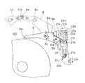
図20において、右センタリングレバー108は回動軸孔108cでサブシャーシ101に回動可能に取り付けられている。トリガーレバー109は、右センタリングレバー108に設けられた回動軸108hに回動可能に取り付けられている。左センタリングレバー111は回動軸孔111cでサブシャーシ101に回動可能に取り付けられている。ディスク検知レバー112は右センタリングレバー108の回動軸108iに回動可能に取り付けられている。ここで、右センタリングレバー108及び左センタリングレバー111は、挿入時におけるディスク120の位置決めを行う、第1、第2の位置決めレバーとしての機能を有している。   In FIG. 20, the right centering lever 108 is pivotally attached to the subchassis 101 through a pivot shaft hole 108c. The trigger lever 109 is rotatably attached to a turning shaft 108 h provided on the right centering lever 108. The left centering lever 111 is rotatably attached to the subchassis 101 through a rotation shaft hole 111c. The disc detection lever 112 is rotatably attached to the turning shaft 108 i of the right centering lever 108. Here, the right centering lever 108 and the left centering lever 111 have functions as first and second positioning levers for positioning the disk 120 at the time of insertion.

図20から図23を参照して、本第2の実施の形態のディスクローディング装置に大径のディスク100を装着するときの動作について説明する。図20から図23はディスク100及び120の挿入動作に関連のある要素のみを図示したディスクローディング装置の上面図である。   With reference to FIG. 20 to FIG. 23, the operation when the large-diameter disk 100 is loaded in the disk loading apparatus of the second embodiment will be described. 20 to 23 are top views of the disk loading apparatus showing only elements related to the inserting operation of the disks 100 and 120. FIG.

図20はディスク100及び120を挿入する前の待機状態を示す。トリガーレバー109の第2の係合部の一例であるディスク当接ピン109a(以下、当接ピン109aという)は、サブシャーシ101に設けられた第2の規制部の一例である規制壁101cを介して回動軸108hと反対側で、規制壁101cと摺動可能な小さな隙間を持った状態にある。規制壁101cは回動軸108hを中心とした円弧状に形成されており、トリガーレバー109の回動に対して、当接ピン109aと規制壁101cの隙間がほぼ同じ状態に保たれるように設けられている。また、右センタリングレバー108の回動軸孔108cと回動軸108hの中心を結ぶ直線と、待機状態(初期位置)にあるトリガーレバー109の当接ピン109aの中心と回動軸108hを結ぶ直線は直角に近い角度に設けられている。また、当接ピン109aは小径ディスク装着領域1eの内部まで入り込んだ状態になっている。ディスク検知レバー112の第1の係合部の一例であるディスク係合ピン112bはサブシャーシ101の第1の規制部の一例である規制壁101dに対向した位置にあり、ディスク当接ピン112a(以下、当接ピン112aという)は小径ディスク装着領域1eの外側で大径ディスク装着領域1dの内側の位置で待機している。

FIG. 20 shows a standby state before the disks 100 and 120 are inserted. A disc contact pin 109a (hereinafter referred to as contact pin 109a), which is an example of a second engagement portion of the trigger lever 109, is provided with a restriction wall 101c, which is an example of a second restriction portion provided in the subchassis 101. On the opposite side to the rotating shaft 108h, there is a small gap that can slide with the regulating wall 101c. The regulation wall 101c is formed in an arc shape centering on the pivot shaft 108h so that the clearance between the contact pin 109a and the regulation wall 101c is kept substantially the same as the trigger lever 109 rotates. Is provided. Further, a straight line connecting the rotation shaft hole 108c of the right centering lever 108 and the center of the rotation shaft 108h, and a straight line connecting the center of the contact pin 109a of the trigger lever 109 in the standby state (initial position) and the rotation shaft 108h. Is provided at an angle close to a right angle. Further, the contact pin 109a is in a state of entering the inside of the small-diameter disk mounting area 1e. The first disk engaging pin 112b which is an example of the engagement portion of the disk detecting lever 112 is in a position facing the restricting wall 101d is an example of a first regulating portion of the sub-chassis 101, disk contact pin 112a The contact pin 112a (hereinafter referred to as the contact pin 112a) stands by at a position outside the small diameter disk mounting area 1e and inside the large diameter disk mounting area 1d.

左センタリングレバー111の位置決めピンの一例であるディスク位置決めピン111aは大径ディスク装着領域1dの左側部分に少し入り込んでいる。右センタリングレバー108のディスク位置決めピン108aは大径ディスク装着領域1dの右側部分に少し入り込んでいる。ディスク位置決めピン108a、111aは小径ディスク装着領域1eの外側に接するように設けられている。右センタリングレバー108のディスク位置決めピン108aと左センタリングレバー111のディスク位置決めピン111aとは、図20に示すように、ディスク挿入方向5aに大径ディスク装着領域1dの中心1fを通る線1gに対して線対称に配置されるとともに、中心1fを通り且つ線1gと直交する線1hよりもディスク挿入方向下流側に配置されている。   A disk positioning pin 111a, which is an example of a positioning pin for the left centering lever 111, slightly enters the left side of the large-diameter disk mounting area 1d. The disk positioning pin 108a of the right centering lever 108 slightly enters the right side portion of the large-diameter disk mounting area 1d. The disk positioning pins 108a and 111a are provided in contact with the outside of the small-diameter disk mounting area 1e. As shown in FIG. 20, the disc positioning pin 108a of the right centering lever 108 and the disc positioning pin 111a of the left centering lever 111 are in relation to a line 1g passing through the center 1f of the large-diameter disc mounting area 1d in the disc insertion direction 5a. They are arranged symmetrically with respect to the line, and are arranged downstream of the line 1h passing through the center 1f and perpendicular to the line 1g in the disc insertion direction.

トリガーレバー109は付勢ばね10の片端により、回動軸108hを中心に反時計方向に付勢されており、ディスク検知レバー112は付勢ばね10のもう一方の端で回動軸108iを中心に反時計方向に付勢されている。左センタリングレバー111はセンタリングレバーばね14により、回動軸孔111cを中心に反時計方向に付勢されている。このばね10、14によって、当接ピン109a、112a、ディスク位置決めピン111aは前述した状態で安定して保持されている。また、右センタリングレバー108は、ディスク位置決めピン108aの反対側の端部に設けた係合ピン108bと左センタリングレバー111の係合孔111bが連結しており、そのため右センタリングレバー108は左センタリングレバー111によって、回動軸108cを中心に時計方向に付勢されている。これにより、ディスク位置決めピン108aは前述の状態で安定して保持されている。   The trigger lever 109 is biased counterclockwise about the rotation shaft 108 h by one end of the biasing spring 10, and the disc detection lever 112 is centered on the rotation shaft 108 i at the other end of the biasing spring 10. Is biased counterclockwise. The left centering lever 111 is urged counterclockwise by the centering lever spring 14 about the rotation shaft hole 111c. By the springs 10 and 14, the contact pins 109a and 112a and the disk positioning pin 111a are stably held in the state described above. Further, the right centering lever 108 is connected to an engagement pin 108b provided at the end opposite to the disk positioning pin 108a and an engagement hole 111b of the left centering lever 111. Therefore, the right centering lever 108 is connected to the left centering lever 108. 111 is biased clockwise about the rotation shaft 108c. Thereby, the disk positioning pin 108a is stably held in the above-described state.

ディスク100を図19に示す挿入口105から矢印5aの方向へ挿入すると、ディスク100がゴムローラ38に接する手前で、スイッチ50が駆動されて閉となる。スイッチ50の閉によりモータ24に通電されたモータ24が回転し、モータ24の回転によりゴムローラ38が回転する。ディスク100が装置内部に押し込まれると、回転しているゴムローラ38はディスク100の厚みにより下方に押される。そのためディスク100はクランプレバー43に固定されたガイドロッド44とゴムローラ38の間に挟まれ、図19の矢印5aの方向に挿入される。   When the disc 100 is inserted in the direction of the arrow 5a from the insertion port 105 shown in FIG. 19, the switch 50 is driven and closed before the disc 100 comes into contact with the rubber roller 38. When the switch 50 is closed, the motor 24 energized to the motor 24 is rotated, and the rubber roller 38 is rotated by the rotation of the motor 24. When the disk 100 is pushed into the apparatus, the rotating rubber roller 38 is pushed downward by the thickness of the disk 100. Therefore, the disc 100 is sandwiched between the guide rod 44 fixed to the clamp lever 43 and the rubber roller 38 and inserted in the direction of the arrow 5a in FIG.

ゴムローラ38の駆動によって挿入されるディスク100は、トリガーレバー109の当接ピン109a及びディスク検知レバー112の当接ピン112aに、ディスク100の外周が当接した後、更に矢印5a方向に移動する。ディスク100の外周がディスク位置決めピン108a及び111aに当接した時点の状態を図21に示す。   The disc 100 inserted by the driving of the rubber roller 38 further moves in the direction of the arrow 5a after the outer periphery of the disc 100 comes into contact with the contact pin 109a of the trigger lever 109 and the contact pin 112a of the disc detection lever 112. FIG. 21 shows a state when the outer periphery of the disk 100 contacts the disk positioning pins 108a and 111a.

図20の状態から図21の状態に移行する過程で、ディスク100に押されたディスク検知レバー112の当接ピン112aは回動軸108i中心に反時計方向に回動する。ディスク検知レバー112の回動により、係合ピン112bも同様に反時計回りに回動し、規制壁101dから離脱する。トリガーレバー109は、当接ピン109aがディスク100の外周に押されて回動軸108hの回りを時計方向に回動し、当接ピン109aが規制壁101cから離脱する。図21は当接ピン109a及び係合ピン112bが規制壁101c、101dから離脱した状態を示している。   In the process of shifting from the state of FIG. 20 to the state of FIG. 21, the contact pin 112a of the disk detection lever 112 pushed by the disk 100 rotates counterclockwise about the rotation shaft 108i. As the disc detection lever 112 is rotated, the engagement pin 112b is also rotated counterclockwise in the same manner, and is released from the regulating wall 101d. In the trigger lever 109, the contact pin 109a is pushed by the outer periphery of the disc 100 and rotates around the rotation shaft 108h in the clockwise direction, and the contact pin 109a is detached from the regulation wall 101c. FIG. 21 shows a state in which the contact pin 109a and the engagement pin 112b are detached from the regulation walls 101c and 101d.

上記の動作により、右センタリングレバー108に設けられた、トリガーレバー109、ディスク検知レバー112が、サブシャーシ101の規制壁101c、101dの規制から開放されるため、右センタリングレバー108は回動軸孔108cを中心に反時計回りに回動可能な状態になっている。また、右センタリングレバー108と係合孔111bで係合している左センタリングレバー111は右センタリングレバー108と連動して回動可能な状態になっている。   By the above operation, the trigger lever 109 and the disc detection lever 112 provided on the right centering lever 108 are released from the restriction of the restriction walls 101c and 101d of the subchassis 101. It is in a state in which it can rotate counterclockwise around 108c. Further, the left centering lever 111 engaged with the right centering lever 108 through the engagement hole 111 b is in a state of being rotatable in conjunction with the right centering lever 108.

ディスク100が更に矢印5a方向に挿入されることにより、ディスク位置決めピン108a、111aはディスク100の外周に押される。このとき右センタリングレバー108及び左センタリングレバー111は回動可能となっているので、ディスク100の外周に応じて開いていく。また、ディスク当接ピン109a、112aも同様にディスク100の外周に応じて開いていく。さらに、ディスク100はゴムローラ38で装置内に挿入されると、支持基板15の壁15a(図19)に当接して停止する。このとき、右センタリングレバー108、左センタリングレバー111は大径ディスク領域1dの外部に押しやられる。また、右センタリングレバー108上に回動中心を持つ、トリガーレバー109及びディスク検知レバー112も同様に大径ディスク領域1dの外部に押しやられ、図22に示す状態になる。   When the disc 100 is further inserted in the direction of the arrow 5a, the disc positioning pins 108a and 111a are pushed to the outer periphery of the disc 100. At this time, since the right centering lever 108 and the left centering lever 111 are rotatable, they are opened according to the outer periphery of the disc 100. Similarly, the disc contact pins 109a and 112a are also opened according to the outer periphery of the disc 100. Further, when the disk 100 is inserted into the apparatus by the rubber roller 38, it comes into contact with the wall 15a (FIG. 19) of the support substrate 15 and stops. At this time, the right centering lever 108 and the left centering lever 111 are pushed outside the large-diameter disk region 1d. Similarly, the trigger lever 109 and the disc detection lever 112 having the center of rotation on the right centering lever 108 are pushed out of the large-diameter disc region 1d, and the state shown in FIG. 22 is obtained.

第1の実施の形態と同様に、この状態で図19に示されているクランパー46を、トラバース47のターンテーブル47aの方向に移動させることにより、ターンテーブル47aがディスク100の中央孔に入り込んで、ディスク100に装着される。この後、ディスク位置決めピン108a、111a、当接ピン109a、112aは、後述する動作により、ディスク100の外周より離れるようになっている。つまり、トリガーレバー109とディスク検知レバー112は退避位置に退避するようになっている。その状態を図23に示す。この状態で、スイッチ50が駆動されてモータ24は停止し、ディスク100の装着が完了する。   Similarly to the first embodiment, in this state, the clamper 46 shown in FIG. 19 is moved in the direction of the turntable 47a of the traverse 47, so that the turntable 47a enters the central hole of the disc 100. The disc 100 is mounted. Thereafter, the disk positioning pins 108a and 111a and the contact pins 109a and 112a are separated from the outer periphery of the disk 100 by an operation described later. That is, the trigger lever 109 and the disc detection lever 112 are retracted to the retracted position. This state is shown in FIG. In this state, the switch 50 is driven, the motor 24 is stopped, and the mounting of the disk 100 is completed.

次に、ディスク100が挿入された後のトリガーレバー109の動作を、図22を参照して詳細に説明する。トリガーレバー109の駆動ピン109bはトリガーロッド21に設けられた溝カム21cと係合している。トリガーロッド21の取り付け状態及び動作は、図7A、図7B、図8A、及び図8Bに示す第1の実施の形態と同様の動作を行う。   Next, the operation of the trigger lever 109 after the disc 100 is inserted will be described in detail with reference to FIG. The drive pin 109 b of the trigger lever 109 is engaged with a groove cam 21 c provided on the trigger rod 21. The attachment state and operation of the trigger rod 21 are the same as those in the first embodiment shown in FIGS. 7A, 7B, 8A, and 8B.

トリガーレバー109と右センタリングレバー108が、挿入されるディスク100の外周に押されて回動すると、トリガーレバー109の駆動ピン109bは、トリガーレバー109の回動に従い、ディスク挿入方向5aと逆方向に移動すると同時に、図22の右方向にも移動する。この動作によりトリガーレバー109の駆動ピン109bが溝カム21eに移動する。この移動により、トリガーロッド21はディスク挿入方向5aと逆方向に移動し、カムロッド23を同方向、つまりディスク挿入方向5aと逆方向に押し込む。この移動により、カムロッド23に設けたラック23mが駆動歯車34aと噛合する。このとき、トリガーレバー109はトリガー位置にある。歯車列34、34a、33、32、35はモータ24により回転しているので、カムロッド23はラック23mを介して、さらに、ディスク挿入方向5aと逆方向に移動する。この移動に伴い、クランプレバー43が上下方向に回動してディスク100をディスク装着位置にクランプする。カムロッド23の詳細な動作は、第1の実施の形態と同様の動作を行うので説明を省略する。   When the trigger lever 109 and the right centering lever 108 are pushed and rotated by the outer periphery of the disc 100 to be inserted, the drive pin 109b of the trigger lever 109 moves in the direction opposite to the disc insertion direction 5a as the trigger lever 109 rotates. Simultaneously with the movement, the movement also moves to the right in FIG. By this operation, the drive pin 109b of the trigger lever 109 moves to the groove cam 21e. By this movement, the trigger rod 21 moves in the direction opposite to the disc insertion direction 5a, and pushes the cam rod 23 in the same direction, that is, in the direction opposite to the disc insertion direction 5a. By this movement, the rack 23m provided on the cam rod 23 meshes with the drive gear 34a. At this time, the trigger lever 109 is at the trigger position. Since the gear trains 34, 34a, 33, 32, and 35 are rotated by the motor 24, the cam rod 23 further moves in the direction opposite to the disk insertion direction 5a via the rack 23m. Along with this movement, the clamp lever 43 rotates in the vertical direction to clamp the disc 100 at the disc mounting position. The detailed operation of the cam rod 23 is the same as that of the first embodiment, and thus the description thereof is omitted.

図23はディスク100のクランプを完了した状態を示している。図22の状態からモータ24の駆動により、更にカムロッド23がディスク挿入方向5aと逆方向に動くと、トリガーロッド21のピン21fは溝カム23aの傾斜部23dに案内されて最上部23eに到達する。この移動の過程で、傾斜部23dにおいてピン21fが図23の左方向に押されて、トリガーロッド21も同様に左方向に移動する。そのため、トリガーロッド21の図7中の上部斜辺によって形成されたカム21gが右センタリングレバー108の回動軸108hを上方に押し上げる。その結果、右センタリングレバー108は回動軸108cを回動中心として反時計方向に回動し、トリガーレバー109は溝カム21eに嵌合された駆動ピン109bを中心として時計方向に回動するため、先端の当接ピン109aはディスク100の外周から離れる。   FIG. 23 shows a state where clamping of the disk 100 is completed. When the cam rod 23 is further moved in the direction opposite to the disc insertion direction 5a by driving the motor 24 from the state of FIG. 22, the pin 21f of the trigger rod 21 is guided by the inclined portion 23d of the groove cam 23a and reaches the uppermost portion 23e. . In the course of this movement, the pin 21f is pushed leftward in FIG. 23 at the inclined portion 23d, and the trigger rod 21 similarly moves leftward. Therefore, the cam 21g formed by the upper hypotenuse in FIG. 7 of the trigger rod 21 pushes the rotating shaft 108h of the right centering lever 108 upward. As a result, the right centering lever 108 rotates counterclockwise about the rotation shaft 108c, and the trigger lever 109 rotates clockwise about the drive pin 109b fitted to the groove cam 21e. The contact pin 109a at the tip is separated from the outer periphery of the disk 100.

また、この動作により、右センタリングレバー108のディスク位置決めピン108aもディスク100の外周から離れる方向に移動する。さらに右センタリングレバー108は係合ピン108bで左センタリングレバー111の係合孔111bで連結されているため、左センタリングレバー111も回動軸孔111cを中心に時計方向に回動して、当接ピン111aもディスク100のターンテーブル47aへの装着の動作を行う。この動作は、第1の実施の形態と同様であるので説明を省略する。   This operation also moves the disc positioning pin 108 a of the right centering lever 108 in a direction away from the outer periphery of the disc 100. Further, since the right centering lever 108 is connected by the engagement pin 108b through the engagement hole 111b of the left centering lever 111, the left centering lever 111 also rotates clockwise around the rotation shaft hole 111c and comes into contact. The pin 111a also performs the operation of mounting the disc 100 on the turntable 47a. Since this operation is the same as that of the first embodiment, a description thereof will be omitted.

ディスク100の装着が完了したとき、前記レバー群がすべて、ディスク100の外周から外側の領域、すなわち大径ディスク装着領域1dの外部にあり、大径ディスク装着領域1dの内部には存在しない。よって、レバー群をディスク100が存在する高さと同じ高さに構成できるため、レバー群をディスクの上方に配置した装置より装置の高さを低くすることが可能となる。   When the mounting of the disk 100 is completed, all the lever groups are located outside the outer periphery of the disk 100, that is, outside the large-diameter disk mounting area 1d, and are not present inside the large-diameter disk mounting area 1d. Therefore, since the lever group can be configured to have the same height as the disk 100 is present, the height of the apparatus can be made lower than the apparatus in which the lever group is disposed above the disk.

次に、規格直径8cmの小径のディスク120をディスクローディング装置に装着するときの動作について、図24から図28を参照して説明する。ディスクローディング装置のディスク挿入口105の横幅は、大径のディスク100の直径より若干大きい寸法になされている。従ってこの横幅は小径のディスク120の直径より大幅に大きい。そのため、使用者がディスクローディング装置にディスク120を挿入するとき、ディスク120が挿入口5のどの部分に挿入されるかわからない。例えば、図24に示す例では、ディスク120を挿入口105の左側の部分に挿入している。また、図26に示す例では、ディスク120を挿入口105の右側の部分に挿入している。   Next, the operation when the small-diameter disk 120 having a standard diameter of 8 cm is mounted on the disk loading apparatus will be described with reference to FIGS. The horizontal width of the disk insertion port 105 of the disk loading device is slightly larger than the diameter of the large-diameter disk 100. Therefore, this lateral width is significantly larger than the diameter of the small-diameter disk 120. Therefore, when the user inserts the disk 120 into the disk loading device, it is not known in which part of the insertion slot 5 the disk 120 is inserted. For example, in the example shown in FIG. 24, the disc 120 is inserted into the left portion of the insertion slot 105. In the example shown in FIG. 26, the disc 120 is inserted into the right portion of the insertion slot 105.

本実施の形態のディスクローディング装置では、ディスク120が挿入口105の、どの位置から挿入されてもディスク120をディスク装着位置に位置決めすることができる。   In the disk loading apparatus of the present embodiment, the disk 120 can be positioned at the disk mounting position regardless of the position of the insertion slot 105 where the disk 120 is inserted.

図24を参照して、挿入口105の左側の部分にディスク120を挿入した場合の動作を説明する。図24は、ディスク120が、挿入口5より挿入された後、左センタリングレバー111のディスク位置決めピン111aと、トリガーレバー109の当接ピン109aとに当接して、トリガーレバー109を回動させ、当接ピン109aがサブシャーシ101の規制壁101cから離れた状態を示している。   With reference to FIG. 24, the operation when the disc 120 is inserted into the left portion of the insertion slot 105 will be described. 24, after the disc 120 is inserted from the insertion port 5, the disc positioning pin 111a of the left centering lever 111 and the contact pin 109a of the trigger lever 109 are contacted to rotate the trigger lever 109. The contact pin 109a is shown in a state separated from the restriction wall 101c of the subchassis 101.

図24において、使用者がディスク120を挿入口105に挿入すると、ゴムローラ38に当接する手前で、前記大径のディスク100を挿入するときと同様に、スイッチ50が閉となりモータ24が回転を開始する。モータ24の回転によりゴムローラ38が回転し、更にディスク120を押し込むと、回転しているゴムローラ38とクランプレバー43に固定されたガイドロッド44の間にディスク120が挟まれ、ディスク120は矢印5aの方向に搬送(挿入)されて、ディスクローディング装置内に入って行く。   In FIG. 24, when the user inserts the disc 120 into the insertion slot 105, the switch 50 is closed and the motor 24 starts to rotate just like when the large-diameter disc 100 is inserted just before contacting the rubber roller 38. To do. When the rubber roller 38 is rotated by the rotation of the motor 24 and the disk 120 is further pushed in, the disk 120 is sandwiched between the rotating rubber roller 38 and the guide rod 44 fixed to the clamp lever 43, and the disk 120 is indicated by the arrow 5a. It is conveyed (inserted) in the direction and enters the disk loading device.

ディスク120は、まず、左センタリングレバー111のディスク位置決めピン111aに当たり、これを押す。ディスク位置決めピン111aは、ディスク120に押されて、図24の時計方向に回動しようとする。しかしながら、連結された右センタリングレバー108は、この右センタリングレバー108に設けられた、トリガーレバー109の当接ピン109aがサブシャーシ101の規制壁101cにより、回動軸108cを中心とする回動を規制されているため、右センタリングレバー108は、ロック状態にある。したがって、右センタリングレバー108と係合ピン108bで連結している左センタリングレバー111もロック状態にあり、ディスク位置決めピン111aは回動できない。
よって、ディスク120はディスク位置決めピン111aに接しながら図24の右方向に移動しつつ、更に挿入されていく。
The disk 120 first hits and pushes the disk positioning pin 111a of the left centering lever 111. The disk positioning pin 111a is pushed by the disk 120 and tries to rotate clockwise in FIG. However, in the connected right centering lever 108, the contact pin 109a of the trigger lever 109 provided on the right centering lever 108 is rotated about the rotation shaft 108c by the restriction wall 101c of the sub chassis 101. Because of the restriction, the right centering lever 108 is in a locked state. Therefore, the left centering lever 111 connected to the right centering lever 108 and the engaging pin 108b is also in a locked state, and the disk positioning pin 111a cannot be rotated.
Therefore, the disk 120 is further inserted while moving to the right in FIG. 24 while being in contact with the disk positioning pin 111a.

さらに挿入されていくと、ディスク120はトリガーレバー109の当接ピン109aに当たり、これを押してトリガーレバー109を図24の時計方向に回動させる。これにより、当接ピン109aは規制壁101cから離脱する。しかしながら、ディスク120は、その位置ではディスク検知レバー112の当接ピン112aからは十分離れており、待機状態の位置にある。よって、ディスク検知レバー112の係合ピン112bは、サブシャーシ101の規制壁101dに回動軸108cを中心とする回動を規制されており、ディスク検知レバー112が設けられている右センタリングレバー108はロック状態が継続され、それに伴い左センタリングレバー111のロック状態も維持される。さらに、ディスク120の挿入動作が継続されると、更にディスク120は図24の右方向へ移動し、最終的にディスク位置決めピン108aにも当接して、挿入動作が完了する。   As the disk 120 is further inserted, the disk 120 hits the contact pin 109a of the trigger lever 109 and pushes it to rotate the trigger lever 109 clockwise in FIG. Thereby, the contact pin 109a is detached from the regulation wall 101c. However, the disk 120 is sufficiently separated from the contact pin 112a of the disk detection lever 112 at that position, and is in a standby state. Therefore, the engagement pin 112b of the disc detection lever 112 is restricted from turning about the turning shaft 108c by the restriction wall 101d of the sub chassis 101, and the right centering lever 108 provided with the disc detection lever 112 is used. The locked state is continued, and accordingly, the locked state of the left centering lever 111 is also maintained. Further, when the insertion operation of the disk 120 is continued, the disk 120 further moves in the right direction in FIG. 24 and finally comes into contact with the disk positioning pin 108a to complete the insertion operation.

図25は挿入動作が完了した状態を示している。ディスク検知レバー112のディスク当接ピン112aは、小径ディスク装着領域1eの外部に設けられているため、ディスク120とは離れた位置にある。そのため、ディスク検知レバー112は初期状態を継続しており、ディスク検知レバー112の係合ピン112bはサブシャーシ101の規制壁101dによって、回動軸孔108cを中心とする回動の規制を受けている。よって、ディスク検知レバー112が設けられた右センタリングレバー108はロックされた状態を継続しており、右センタリングレバー108と係合ピン108bで係合して連動している左センタリングレバー111もロック状態を維持している。右センタリングレバー108はロック状態にあるので、回動軸108hは移動せずに固定される。そのため、ディスク120の外周で当接ピン109aを押されたトリガーレバー109は、回動軸108hを中心に時計回りに回動し、当接ピン109aと反対側に設けられたカムピン109bは、トリガーロッド21の溝カム21cから溝カム21hの入り口の壁21k(図14A)に当接して、トリガーロッド21をディスク挿入方向5aと逆方向に移動させる。トリガーロッド21は支持基板15に設けられたガイド部20dで移動が規制されるため、途中から移動が規制されて止まる。図25は規制を受けたときの状態を示している。トリガーロッド21が規制を受けたことにより、トリガーレバー109の回動動作も規制を受けて、それ以上回動できなくなり、当接ピン109aの移動もそこで規制を受ける。   FIG. 25 shows a state where the insertion operation is completed. Since the disk contact pin 112a of the disk detection lever 112 is provided outside the small-diameter disk mounting area 1e, it is located away from the disk 120. Therefore, the disk detection lever 112 continues in the initial state, and the engagement pin 112b of the disk detection lever 112 is subjected to the rotation restriction around the rotation shaft hole 108c by the restriction wall 101d of the sub chassis 101. Yes. Therefore, the right centering lever 108 provided with the disc detection lever 112 continues to be locked, and the left centering lever 111 that is engaged and interlocked with the right centering lever 108 by the engaging pin 108b is also locked. Is maintained. Since the right centering lever 108 is in a locked state, the rotation shaft 108h is fixed without moving. Therefore, the trigger lever 109 whose contact pin 109a is pushed on the outer periphery of the disk 120 rotates clockwise around the rotation shaft 108h, and the cam pin 109b provided on the opposite side of the contact pin 109a The trigger rod 21 is moved in the direction opposite to the disc insertion direction 5a by coming into contact with the wall 21k (FIG. 14A) at the entrance of the groove cam 21h from the groove cam 21c of the rod 21. Since the movement of the trigger rod 21 is restricted by the guide portion 20d provided on the support substrate 15, the movement is restricted from the middle and stops. FIG. 25 shows a state when the regulation is received. Due to the restriction of the trigger rod 21, the turning operation of the trigger lever 109 is also restricted and cannot be further rotated, and the movement of the contact pin 109a is also restricted there.

以上の動作により、ディスク120がディスク位置決めピン108a、111a、及び当接ピン109aの3つのピンにより位置決めされる。
また、ディスク120が中央部から挿入された場合も同様の動作にて、最終的に図25に示される状態でディスク120がディスク位置決めピン108a、111a、及び当接ピン109aの3つのピンにより位置決めされる。
With the above operation, the disk 120 is positioned by the three pins of the disk positioning pins 108a and 111a and the contact pin 109a.
Further, when the disc 120 is inserted from the center portion, the same operation is performed, and the disc 120 is finally positioned by the three pins of the disc positioning pins 108a and 111a and the contact pin 109a in the state shown in FIG. Is done.

次に、図26を参照して、ディスク120を挿入口105の右側部分から挿入した場合の動作を説明する。挿入されたディスク120は、まず、ディスク検知レバー112の当接ピン112aに当接し、ディスク検知レバー112を、回動軸108iを中心に反時計回りに回動させる。この回動により、ディスク検知レバー112の係合ピン112bはサブシャーシ101の規制壁101dから離脱する。さらに、ディスク120が挿入されると、ディスク120は右センタリングレバー108のディスク位置決めピン108aに当たる。ディスク位置決めピン108aはトリガーレバー109の当接ピン109aでサブシャーシ101の規制壁101cから回動軸108cを中心とする回動を規制されているため、ディスク位置決めピン108aは動かない。そのためディスク120はディスク位置決めピン108aに接しつつ、図26の左上方に移動する。   Next, with reference to FIG. 26, the operation when the disk 120 is inserted from the right side of the insertion slot 105 will be described. The inserted disk 120 first contacts the contact pin 112a of the disk detection lever 112, and rotates the disk detection lever 112 counterclockwise about the rotation shaft 108i. By this rotation, the engagement pin 112b of the disc detection lever 112 is detached from the restriction wall 101d of the subchassis 101. Further, when the disc 120 is inserted, the disc 120 hits the disc positioning pin 108 a of the right centering lever 108. Since the disk positioning pin 108a is restricted from rotating about the rotation shaft 108c from the restriction wall 101c of the subchassis 101 by the contact pin 109a of the trigger lever 109, the disk positioning pin 108a does not move. Therefore, the disc 120 moves to the upper left in FIG. 26 while contacting the disc positioning pin 108a.

図27は、さらにディスク120が挿入された状態を示している。さらにディスク120が挿入されると、ディスク120は当接ピン109aに当接し、これを押しながら移動する。これに従い、トリガーレバー109の当接ピン109aが規制壁101cから離脱していく。しかしながら、ディスク120が左方向(中央部)に移動するに従い、ディスク検知レバー112の当接ピン112aは付勢ばね10によって、ディスク120の外周に沿いながら、元の状態に戻っていく。図27は当接ピン109aが規制壁101cから離れる瞬間の状態を示しているが、このとき、ディスク検知レバー112の係合ピン112bは規制壁101dに規制される位置まで戻っている。したがって、トリガーレバー109の当接ピン109aが完全に規制壁101cを離脱しても、右センタリングレバー108は係合ピン112bによってロック状態が維持されており、右センタリングレバー108と係合している左センタリングレバー111も同様にロック状態が維持される。さらに、ディスク120の挿入動作が継続されると、ディスク120は図27の右方向に移動しつつ、最終的にディスク位置決めピン108aにも当接して、挿入動作が完了し、図25に示した状態になる。   FIG. 27 shows a state where the disc 120 is further inserted. When the disc 120 is further inserted, the disc 120 comes into contact with the contact pin 109a and moves while pushing it. Accordingly, the contact pin 109a of the trigger lever 109 is detached from the regulation wall 101c. However, as the disc 120 moves to the left (center), the contact pin 112a of the disc detection lever 112 returns to its original state along the outer periphery of the disc 120 by the biasing spring 10. FIG. 27 shows a state at the moment when the contact pin 109a is separated from the restriction wall 101c. At this time, the engagement pin 112b of the disc detection lever 112 has returned to the position restricted by the restriction wall 101d. Therefore, even if the contact pin 109a of the trigger lever 109 is completely removed from the restriction wall 101c, the right centering lever 108 is kept locked by the engagement pin 112b and is engaged with the right centering lever 108. Similarly, the left centering lever 111 is maintained in the locked state. Further, when the insertion operation of the disc 120 is continued, the disc 120 moves to the right in FIG. 27 and finally comes into contact with the disc positioning pin 108a to complete the insertion operation, as shown in FIG. It becomes a state.

このとき、前述した挿入口5の左側から挿入した場合と同様に、右センタリングレバー108のディスク位置決めピン108a、左センタリングレバー111のディスク位置決めピン111a、及びトリガーレバー109の当接ピン109aの3つのピンによりディスク120が位置決めされる。   At this time, similarly to the case where the insertion is made from the left side of the insertion port 5 described above, the disk positioning pin 108a of the right centering lever 108, the disk positioning pin 111a of the left centering lever 111, and the contact pin 109a of the trigger lever 109 are provided. The disk 120 is positioned by the pins.

以上のように、トリガーレバー109の当接ピン109aとディスク検知レバー112の係合ピン112bが、同時に規制壁101c、101dから離脱することなく、どちらか一方が右センタリングレバー108をロックしているため、右センタリングレバー108が開いて、ディスク120が行き過ぎることなく位置決めされる。したがって、ディスク120が装置内に落ち込んで出なくなることがない。   As described above, the contact pin 109a of the trigger lever 109 and the engagement pin 112b of the disc detection lever 112 are not separated from the restriction walls 101c and 101d at the same time, and one of them locks the right centering lever 108. Therefore, the right centering lever 108 is opened and the disk 120 is positioned without going too far. Therefore, the disk 120 does not fall into the apparatus and cannot come out.

また、ディスク120を右センタリングレバー108と左センタリングレバー111と共同して位置決めするトリガーレバー109と、右センタリングレバー108にロックを行うディスク検知レバー112とを、右センタリングレバー108に取付けている。これにより、トリガーレバー109の回動軸108hが精度良くディスク検知レバー112で固定され、トリガーレバー109の当接ピン109aの位置精度が向上する。したがって、ディスク120の位置決め精度が上がり、着座ミスを起こさなくすることが可能になる。   Further, a trigger lever 109 that positions the disk 120 in cooperation with the right centering lever 108 and the left centering lever 111 and a disk detection lever 112 that locks the right centering lever 108 are attached to the right centering lever 108. Thereby, the rotation shaft 108h of the trigger lever 109 is fixed with high accuracy by the disc detection lever 112, and the positional accuracy of the contact pin 109a of the trigger lever 109 is improved. Therefore, the positioning accuracy of the disk 120 is improved, and it becomes possible to prevent a seating error.

また、ディスク検知レバー112及びトリガーレバー109をロックする規制壁101c、101dを、右センタリングレバー108、左センタリングレバー111が設けられているサブシャーシ101に設けている。したがって、サブシャーシ101と支持基板15との取付け誤差がないため、ディスク120のセンタリング精度を向上でき、着座ミスをなくすことが可能である。   Further, the restriction walls 101c and 101d for locking the disc detection lever 112 and the trigger lever 109 are provided in the sub chassis 101 provided with the right centering lever 108 and the left centering lever 111. Therefore, since there is no attachment error between the sub-chassis 101 and the support substrate 15, the centering accuracy of the disk 120 can be improved, and a seating error can be eliminated.

また、トリガーレバー109の、規制壁101cとの係合部をディスク120と当接する当接ピン109aで行っている。これにより、右センタリングレバー108のロック位置の精度を向上できるため、ディスク検知レバー112の規制壁101dに対する精度を向上できる。したがって、トリガーレバー109とディスク検知レバー112のロックが同時に外れることをなくすことができ、右センタリングレバー108のロックを安定して行うことができる。   Further, the engaging portion of the trigger lever 109 with the regulating wall 101c is performed by the contact pin 109a that contacts the disk 120. Thereby, since the accuracy of the lock position of the right centering lever 108 can be improved, the accuracy of the disc detection lever 112 with respect to the restriction wall 101d can be improved. Therefore, the trigger lever 109 and the disc detection lever 112 can be prevented from being unlocked at the same time, and the right centering lever 108 can be locked stably.

次に、前述のディスク120の位置決めの動作において、最終の位置決めがなされて図25の状態になる直前のトリガーレバー109の動作を、図28を参照しつつ説明する。トリガーレバー109の回動によって、トリガーレバー109の駆動ピン109bが、溝カム21cから溝カム21hの入り口の壁21kに移動し、トリガーロッド21をディスク挿入方向5aと逆方向に押す。これにより、ガイドピン21a、21bは、付勢ばね22の付勢力に抗してガイド孔20a、20bの傾斜ガイド部20cの上端から下端に移動する。これにより、図14Aに示すように、トリガーロッド21の端面21jがカムロッド23のピン23bを同方向、つまりディスク挿入方向5aと逆方向に押し、カムロッド23は図28の下方に移動する。その結果、前述の大径のディスク100の場合と同様に、カムロッド23に設けたラック23mが駆動小歯車34aと噛合する。このとき、トリガーレバー109は、トリガー位置にある。駆動小歯車34aはモータ24により駆動されているので、カムロッド23を更にディスク挿入方向5aと逆方向に移動し、その結果、ピン21fが溝カム23aの傾斜部23dに案内されて最上部23eに到達する。この移動の過程で、傾斜部23dによってピン21fが左方向に押されるので、トリガーロッド21は同様に左方向に移動する。この移動により、駆動ピン109bは、溝カム21cの傾斜部23dに案内され、回動軸108hを中心に時計方向に回動する。これにより、当接ピン109aは時計方向に回動し、ディスク120の外周から離れる。つまり、トリガーレバー109は退避位置に移動する。   Next, in the positioning operation of the disk 120 described above, the operation of the trigger lever 109 immediately before the final positioning is performed and the state shown in FIG. 25 is described with reference to FIG. With the rotation of the trigger lever 109, the drive pin 109b of the trigger lever 109 moves from the groove cam 21c to the wall 21k at the entrance of the groove cam 21h, and pushes the trigger rod 21 in the direction opposite to the disk insertion direction 5a. As a result, the guide pins 21 a and 21 b move from the upper end to the lower end of the inclined guide portion 20 c of the guide holes 20 a and 20 b against the urging force of the urging spring 22. Thereby, as shown in FIG. 14A, the end surface 21j of the trigger rod 21 pushes the pin 23b of the cam rod 23 in the same direction, that is, in the direction opposite to the disc insertion direction 5a, and the cam rod 23 moves downward in FIG. As a result, as in the case of the large-diameter disk 100 described above, the rack 23m provided on the cam rod 23 meshes with the drive small gear 34a. At this time, the trigger lever 109 is at the trigger position. Since the driving small gear 34a is driven by the motor 24, the cam rod 23 is further moved in the direction opposite to the disk insertion direction 5a. As a result, the pin 21f is guided by the inclined portion 23d of the groove cam 23a and moved to the uppermost portion 23e. To reach. In the course of this movement, the pin 21f is pushed leftward by the inclined portion 23d, so that the trigger rod 21 similarly moves leftward. By this movement, the drive pin 109b is guided by the inclined portion 23d of the groove cam 21c and rotates clockwise about the rotation shaft 108h. As a result, the contact pin 109a rotates clockwise and moves away from the outer periphery of the disk 120. That is, the trigger lever 109 moves to the retracted position.

ディスク位置決めピン108a及び111aは第1の実施の形態のディスク位置決めピン8a及び11aと同様に、小径部と、小径部より径の大きい大径部とを有している。ディスク120がクランプされると、ディスク120と、ディスク位置決めピン108a及び111aの小径部との間に、それらが接触しないように隙間を設けることができる。したがって、ディスク120の記録及び再生時、ディスク120の回転の妨げとならない。   As with the disk positioning pins 8a and 11a of the first embodiment, the disk positioning pins 108a and 111a have a small-diameter portion and a large-diameter portion having a larger diameter than the small-diameter portion. When the disk 120 is clamped, a gap can be provided between the disk 120 and the small diameter portions of the disk positioning pins 108a and 111a so that they do not come into contact with each other. Therefore, the rotation of the disk 120 is not hindered during recording and reproduction of the disk 120.

ディスク120のターンテーブル47aへの装着の動作は第1の実施の形態と同様であるので、説明を省略する。
また、装着したディスク100又は120をディスクローディング装置から取り出す動作については説明を省略する。
Since the operation of mounting the disc 120 on the turntable 47a is the same as that of the first embodiment, the description thereof is omitted.
Further, the description of the operation of taking out the loaded disc 100 or 120 from the disc loading device is omitted.

本発明の第2の実施の形態によれば、大径のディスク100をディスクローディング装置に装着したとき、ディスク100を位置決めするための、右センタリングレバー108、トリガーレバー109、左センタリングレバー111及びディスク検知レバー112を含むすべてのディスク位置決め機構要素が、ディスク100の装着領域1dの外部にあり、ディスク100、120と同じ高さで機構が構成できる。したがって、ディスク100、120の上部にディスク位置決め機構を配置した装置と比較して、ディスクローディング装置の厚みを薄くすること(薄型化)が可能となる。   According to the second embodiment of the present invention, the right centering lever 108, the trigger lever 109, the left centering lever 111, and the disk for positioning the disk 100 when the large-diameter disk 100 is mounted on the disk loading device. All the disk positioning mechanism elements including the detection lever 112 are outside the mounting area 1d of the disk 100, and the mechanism can be configured at the same height as the disks 100 and 120. Therefore, the thickness of the disk loading device can be reduced (thinned) as compared with a device in which the disk positioning mechanism is disposed above the disks 100 and 120.

また、本発明の第2の実施の形態では、ディスク検知レバー112とトリガーレバー109が同じレバー(右センタリングレバー108)上に設けられているため、付勢ばね10を共有することができ、コストを下げることが可能である。また、右センタリングレバー108及び左センタリングレバー111の剛性が弱い場合でも、トリガーレバー109が設けられている右センタリングレバー108が直接、ディスク検知レバー112でロックされるため、ディスク120の搬送力で右センタリングレバー108が撓んでトリガーレバー109の回動軸108hが移動することがない。したがって、ディスク120の位置決め精度が向上し、着座ミスを起こさない。また、右センタリングレバー108及び左センタリングレバー111の材質を安価な剛性の小さい材料にできコストを下げることが可能となる。   Further, in the second embodiment of the present invention, since the disc detection lever 112 and the trigger lever 109 are provided on the same lever (right centering lever 108), the biasing spring 10 can be shared, and the cost is reduced. Can be lowered. Even when the rigidity of the right centering lever 108 and the left centering lever 111 is weak, the right centering lever 108 provided with the trigger lever 109 is directly locked by the disc detection lever 112. The centering lever 108 is not bent and the rotation shaft 108h of the trigger lever 109 does not move. Therefore, the positioning accuracy of the disk 120 is improved and no seating error occurs. In addition, the right centering lever 108 and the left centering lever 111 can be made of an inexpensive and low-rigidity material, and the cost can be reduced.

また、本発明の第2の実施の形態では、ディスク検知レバー112及びトリガーレバー109をロックする規制壁101c、101dを、右センタリングレバー108、左センタリングレバー111が設けられているサブシャーシ101に設けている。すなわち、図29に示すように、ディスク検知レバー112、トリガーレバー109、右センタリングレバー108、左センタリングレバー111、及び規制部101c、101dの全てを、サブシャーシ101に設けている。これにより、サブシャーシ101と支持基板15との取付け誤差がないため、ディスク120のセンタリング精度を向上でき、着座ミスをなくすことが可能である。なお、ディスク検知レバー112、トリガーレバー109、右センタリングレバー108、左センタリングレバー111、及び規制部101c、101dの全てを、支持基板15に設けても同様の効果を得ることができる。   In the second embodiment of the present invention, the restriction walls 101c and 101d for locking the disc detection lever 112 and the trigger lever 109 are provided on the subchassis 101 provided with the right centering lever 108 and the left centering lever 111. ing. That is, as shown in FIG. 29, all of the disk detection lever 112, the trigger lever 109, the right centering lever 108, the left centering lever 111, and the restriction portions 101c and 101d are provided in the sub chassis 101. Thereby, since there is no attachment error of the subchassis 101 and the support substrate 15, the centering accuracy of the disk 120 can be improved, and a seating error can be eliminated. The same effect can be obtained even if the disc detection lever 112, the trigger lever 109, the right centering lever 108, the left centering lever 111, and the restriction portions 101c and 101d are all provided on the support substrate 15.

また、本発明の第2の実施の形態では、ディスク120の外周と当接するトリガーレバー109の当接ピン109aを、規制壁101cと係合させている。これにより、右センタリングレバー108のロック位置の精度が向上するため、ディスク検知レバー112の規制壁101dに対する精度を向上でき、右センタリングレバー108のロックを安定化して、品質を向上できる。   In the second embodiment of the present invention, the contact pin 109a of the trigger lever 109 that contacts the outer periphery of the disk 120 is engaged with the restriction wall 101c. Thereby, since the accuracy of the lock position of the right centering lever 108 is improved, the accuracy of the disc detection lever 112 with respect to the restriction wall 101d can be improved, and the lock of the right centering lever 108 can be stabilized and the quality can be improved.

なお、本発明は上記各実施の形態に限定されるものではなく、その他種々の態様で実施できる。例えば、上記各実施の形態では、右センタリングレバー(8、108)、トリガーレバー(9、109)、左センタリングレバー(11、111)、及びディスク検知レバー(12、112)が、それぞれの軸で支持され回転動作で移動するように構成されているが、これらの要素がスライド機構やリンク機構などにより直線移動(線形動作)をするように構成してもよい。
また、右センタリングレバー(8、108)の係合ピン(8b、108b)、トリガーレバー(9、109)の係合ピン(9a、109a)及び駆動ピン(9b、109b)、左センタリングレバー(11、111)の係合孔(11b、111b)、及びディスク検知レバー(12、112)のディスク検知ピン(12a、112a)を、それぞれのレバーの先端或いは端部に設けたが、本発明はこれに限定されない。各機能を果たす位置であれば、各レバー中のいずれの位置に設けられてもよい。
In addition, this invention is not limited to said each embodiment, It can implement in another various aspect. For example, in each of the above embodiments, the right centering lever (8, 108), the trigger lever (9, 109), the left centering lever (11, 111), and the disc detection lever (12, 112) are connected to the respective axes. Although it is configured to be supported and moved by a rotating operation, these elements may be configured to move linearly (linear operation) by a slide mechanism, a link mechanism, or the like.
Also, the engagement pins (8b, 108b) of the right centering lever (8, 108), the engagement pins (9a, 109a) and the drive pins (9b, 109b) of the trigger lever (9, 109), the left centering lever (11 , 111) and the disc detection pins (12a, 112a) of the disc detection levers (12, 112) are provided at the tips or ends of the levers. It is not limited to. Any position in each lever may be provided as long as the position fulfills each function.

なお、上記様々な実施形態のうちの任意の実施形態を適宜組み合わせることにより、それぞれの有する効果を奏するようにすることができる。   It is to be noted that, by appropriately combining arbitrary embodiments of the various embodiments described above, the effects possessed by them can be produced.

本発明は、大径ディスクと小径ディスクを共用できる薄型ディスクローディング装置に利用可能である。   The present invention can be used in a thin disk loading apparatus that can share a large diameter disk and a small diameter disk.

本発明の第1の実施の形態のディスクローディング装置の上面図The top view of the disk loading apparatus of the 1st Embodiment of this invention 本発明の第1の実施の形態のディスクローディング装置の分解斜視図1 is an exploded perspective view of a disk loading device according to a first embodiment of the present invention. 本発明の第1の実施の形態のディスクローディング装置のディスクを挿入する前の状態を示す一部上面図The partial top view which shows the state before inserting the disc of the disc loading apparatus of the 1st Embodiment of this invention 本発明の第1の実施の形態のディスクローディング装置において、大径ディスクを挿入している途中の一部上面図In the disk loading apparatus of the first embodiment of the present invention, a partial top view in the middle of inserting a large-diameter disk 本発明の第1の実施の形態のディスクローディング装置において、大径ディスクの挿入時の移動が停止した状態を示す一部上面図The partial top view which shows the state which the movement at the time of insertion of a large diameter disc stopped in the disc loading apparatus of the 1st Embodiment of this invention 本発明の第1の実施の形態のディスクローディング装置において、大径ディスクの装着が完了した状態を示す一部上面図1 is a partial top view showing a state in which a large-diameter disk has been mounted in the disk loading apparatus according to the first embodiment of the present invention; 本発明の第1の実施の形態のディスクローディング装置において、ディスクを挿入する前のトリガーレバーの状態を示す一部上面図The partial top view which shows the state of the trigger lever before inserting the disk in the disk loading apparatus of the 1st Embodiment of this invention. 図7Aのトリガーロッドの移動の説明図Explanatory drawing of movement of trigger rod of FIG. 7A 本発明の第1の実施の形態のディスクローディング装置において、ディスクを挿入している途中のトリガーレバーの状態を示す一部上面図The top view which shows the state of the trigger lever in the middle of inserting the disk in the disk loading apparatus of the 1st Embodiment of this invention 図8Aのトリガーロッドの移動の説明図Explanatory drawing of movement of trigger rod of FIG. 8A 本発明の第1の実施の形態のディスクローディング装置において、ディスクの装着完了後のトリガーレバーの状態を示す一部上面図1 is a partial top view showing a state of a trigger lever after completion of loading of a disk in the disk loading apparatus according to the first embodiment of the present invention; 図9Aのトリガーロッドの移動の説明図Explanatory drawing of movement of trigger rod of FIG. 9A 本発明の第1の実施の形態のディスクローディング装置において、小径ディスクを、挿入口の左側から挿入するときの一部上面図In the disk loading apparatus of the first embodiment of the present invention, a partial top view when a small-diameter disk is inserted from the left side of the insertion slot 本発明の第1の実施の形態のディスクローディング装置において、小径ディスクを挿入口の右側から挿入するときの一部上面図1 is a partial top view when a small-diameter disk is inserted from the right side of an insertion slot in the disk loading apparatus according to the first embodiment of the present invention; 本発明の第1の実施の形態のディスクローディング装置において、小径ディスクを挿入している途中の一部上面図In the disk loading apparatus of the first embodiment of the present invention, a partial top view in the middle of inserting a small-diameter disk 本発明の第1の実施の形態のディスクローディング装置において、小径ディスクの装填完了後の一部上面図In the disk loading apparatus of the first embodiment of the present invention, a partial top view after completion of loading of a small-diameter disk 本発明の第1の実施の形態のディスクローディング装置において、小径ディスクの挿入時のトリガーレバーの動作を示す一部上面図The partial top view which shows operation | movement of the trigger lever at the time of insertion of a small diameter disc in the disc loading apparatus of the 1st Embodiment of this invention 図14Aのトリガーロッドの移動の説明図Explanatory drawing of movement of trigger rod of FIG. 14A 本発明の第1の実施の形態のディスクローディング装置において、小径ディスクの装着完了時のトリガーレバーの状態を示す一部上面図The top view which shows the state of the trigger lever at the time of completion | finish of mounting | wearing of a small diameter disc in the disc loading apparatus of the 1st Embodiment of this invention 図15Aのトリガーロッドの移動の説明図Explanatory drawing of movement of trigger rod of FIG. 15A 本発明の第1の実施の形態のディスクローディング装置において、小径ディスク装填途中の図11の右側面図11 is a right side view of FIG. 11 in the middle of loading a small-diameter disk in the disk loading apparatus according to the first embodiment of the present invention. 本発明の第1の実施の形態のディスクローディング装置において、小径ディスク装填途中の図12の右側面図12 is a right side view of FIG. 12 during loading of a small-diameter disk in the disk loading apparatus according to the first embodiment of the present invention. 本発明の第1の実施の形態のディスクローディング装置において、小径ディスク装填完了後の図13の右側面図FIG. 13 is a right side view of FIG. 13 after completion of loading of the small-diameter disk in the disk loading apparatus according to the first embodiment of the present invention. 本発明の第2の実施の形態のディスクローディング装置の分解斜視図The disassembled perspective view of the disc loading apparatus of the 2nd Embodiment of this invention 本発明の第2の実施の形態のディスクローディング装置において、待機状態を示す上面図The top view which shows a standby state in the disc loading apparatus of the 2nd Embodiment of this invention 本発明の第2の実施の形態のディスクローディング装置において、大径ディスク挿入状態を示す上面図The top view which shows the large diameter disc insertion state in the disc loading apparatus of the 2nd Embodiment of this invention 本発明の第2の実施の形態のディスクローディング装置において、大径ディスク挿入の際のトリガーロッドの動作を示す一部上面図A partial top view showing the operation of the trigger rod when inserting a large-diameter disk in the disk loading apparatus of the second embodiment of the present invention 本発明の第2の実施の形態のディスクローディング装置において、大径ディスクの装着完了状態を示す上面図The top view which shows the mounting completion state of a large diameter disc in the disc loading apparatus of the 2nd Embodiment of this invention 本発明の第2の実施の形態のディスクローディング装置において、小径ディスクを挿入口の左側から挿入するときの一部上面図Partial top view when inserting a small diameter disc from the left side of an insertion slot in the disc loading apparatus of the 2nd Embodiment of this invention. 本発明の第2の実施の形態のディスクローディング装置において、小径ディスクのディスク位置決め完了状態を示す一部上面図FIG. 7 is a partial top view showing a disk positioning completion state of a small-diameter disk in the disk loading apparatus according to the second embodiment of the present invention. 本発明の第2の実施の形態のディスクローディング装置において、小径ディスクを挿入口の右側から挿入するときの一部上面図Partial top view when inserting a small diameter disc from the right side of an insertion slot in the disc loading apparatus of the 2nd Embodiment of this invention. 本発明の第2の実施の形態のディスクローディング装置において、小径ディスクを挿入口の右側から挿入するときの別の状態を示す一部上面図In the disk loading apparatus of the 2nd Embodiment of this invention, the partial top view which shows another state when inserting a small diameter disk from the right side of an insertion port 本発明の第2の実施の形態のディスクローディング装置において、小径ディスク挿入の際のトリガーロッドの動作を示す一部上面図A partial top view showing an operation of a trigger rod when a small-diameter disk is inserted in the disk loading apparatus according to the second embodiment of the present invention. 本発明の第2の実施形態のディスクローディング装置において、サブシャーシに設けられる部品を説明するための分解斜視図The disassembled perspective view for demonstrating the components provided in a subchassis in the disc loading apparatus of the 2nd Embodiment of this invention.

符号の説明Explanation of symbols

1、101 サブシャーシ
2a、2b 開口部
5、105 挿入口
8、108 右センタリングレバー
8a、11a、108a、111a ディスク位置決めピン
8b、108b 係合ピン
9、109 トリガーレバー
9a、109a ディスク係合ピン
9d カムピン
10 付勢ばね
11、111 左センタリングレバー
11b、111b 係合孔
11c 支点孔
12、112 ディスク検知レバー
12a ディスク検知ピン
15 支持基板
15a 壁
16 トラバース取付孔
19 右ストッパー
21 トリガーロッド
21c 溝カム 23 カムロッド
23a 溝カム
24 モータ
26 ベルト
27 ウオームプーリ
29 回動軸
30 ウオームホイールB
31 ウオームギア
36 ローラ軸
37 ローラ歯車
38 ゴムローラ
39 ローラレバー
40 左軸受
41 右軸受
43 クランプレバー
45 押え板ばね
46 クランパー
47 トラバース
47a ターンテーブル
47b 光ピックアップ
48a、48b、48c 取付けねじ
100a、100b規制壁
108c、111c 回動軸孔
108h、108i 回動軸
109a、112a 当接ピン
109b 駆動ピン
1, 101 Subchassis 2a, 2b Opening 5, 105 Insertion slot 8, 108 Right centering lever 8a, 11a, 108a, 111a Disc positioning pin 8b, 108b Engaging pin 9, 109 Trigger lever 9a, 109a Disc engaging pin 9d Cam pin 10 Biasing spring 11, 111 Left centering lever 11b, 111b Engagement hole 11c Supporting hole 12, 112 Disc detection lever 12a Disc detection pin 15 Support substrate 15a Wall 16 Traverse mounting hole 19 Right stopper 21 Trigger rod 21c Groove cam 23 Cam rod 23a Groove cam 24 Motor 26 Belt 27 Worm pulley 29 Rotating shaft 30 Worm wheel B
31 Worm gear 36 Roller shaft 37 Roller gear 38 Rubber roller 39 Roller lever 40 Left bearing 41 Right bearing 43 Clamp lever 45 Presser plate spring 46 Clamper 47 Traverse 47a Turntable 47b Optical pickup 48a, 48b, 48c Mounting screw 100a, 100b Restriction wall 108c, 111c Rotating shaft hole 108h, 108i Rotating shaft 109a, 112a Contact pin 109b Drive pin

Claims (8)

装着された大径ディスク又は小径ディスクに平行であり、前記各ディスクの上面に対向する部分に開口を有する第1の基板、
前記第1の基板に組み合わせて筐体を構成する第2の基板、
前記装着された大径ディスクが存在する領域である大径ディスク装着領域、の外部において前記第1及び第2の基板のいずれか一方に移動可能に取り付けられ、前記各ディスクが装着されていないとき、一部が前記大径ディスク装着領域の内部に突出している第1の位置決めレバー、
前記第1の位置決めレバーに移動可能に取り付けられ、一部が前記大径ディスク装着領域の内部に突出している第1の検知レバー、
前記ディスク装着領域の外部において、前記第1及び第2の基板のいずれか一方に移動可能に取り付けられ、前記各ディスクが装着されていないとき、一部が前記大径ディスク装着領域の内部に突出している第2の位置決めレバー、及び
前記第2の位置決めレバーに移動可能に取り付けられ、一部が前記大径ディスク装着領域の内部に突出している第2の検知レバーを有し、
前記小径ディスクを装着する場合は、前記第1及び第2の位置決めレバーによって前記小径ディスクがディスク装着位置に位置決めされ、
前記大径ディスクを装着する場合は、前記第1及び第2の検知レバーの両方が前記大径ディスクを検知すると、前記第1及び第2の位置決めレバーが、前記大径ディスクに押されて前記ディスク装着領域の外部へ移動する、ディスクローディング装置。
A first substrate parallel to the mounted large-diameter disk or small-diameter disk and having an opening in a portion facing the upper surface of each disk;
A second substrate constituting a housing in combination with the first substrate;
When attached to either one of the first and second substrates outside the large-diameter disk mounting area, which is an area where the mounted large-diameter disk exists, and when each of the disks is not mounted A first positioning lever partially projecting into the large-diameter disk mounting area;
A first detection lever that is movably attached to the first positioning lever, and a part of which protrudes into the large-diameter disk mounting area;
Outside the disk mounting area, it is movably attached to one of the first and second substrates, and when each disk is not mounted, a part projects into the large-diameter disk mounting area. A second positioning lever, and a second detection lever that is movably attached to the second positioning lever and that partially protrudes into the large-diameter disk mounting area,
When mounting the small-diameter disk, the small-diameter disk is positioned at the disk mounting position by the first and second positioning levers,
When the large-diameter disk is mounted, when both the first and second detection levers detect the large-diameter disk, the first and second positioning levers are pushed by the large-diameter disk and the A disk loading device that moves outside the disk loading area.
装置内に挿入される前記大径ディスクに押されて、前記第1及び第2の検知レバーがともに移動するときのみ、前記第1及び第2の位置決めレバーが、当該移動により、ともにロック状態が解除されて移動可能となるように構成されている、請求項1記載のディスクローディング装置。   Only when the first and second detection levers are moved together by being pushed by the large-diameter disk inserted into the apparatus, the first and second positioning levers are both locked by the movement. The disc loading device according to claim 1, wherein the disc loading device is configured to be released and movable. 前記第1及び第2の検知レバーのいずれか一方の、前記大径ディスク挿入時の移動において、前記第1及び第2の検知レバーのいずれか一方が、初期位置からトリガー位置まで移動する間に、前記第1及び第2の位置決めレバーを移動可能にし、前記トリガー位置から前記大径ディスク装着領域の外部にある退避位置まで移動する間に、前記ディスクをターンテーブルにクランプする駆動機構が駆動するように構成されている、請求項1記載のディスクローディング装置。   During movement of either one of the first and second detection levers when the large-diameter disk is inserted, while either one of the first or second detection levers moves from the initial position to the trigger position. The drive mechanism that clamps the disk to the turntable is driven while the first and second positioning levers are movable and moved from the trigger position to a retracted position outside the large-diameter disk mounting area. The disk loading device according to claim 1, configured as described above. 装着された大径ディスク又は小径ディスクに平行である第1の基板と、
前記第1の基板に組み合わせて筐体を構成する第2の基板を備え、
装着された前記大径ディスクが存在する領域である大径ディスク装着領域の、外部において、前記第1及び第2の基板のいずれか一方に回転軸を有して、前記各ディスクが装填されていないとき、一部が前記大径ディスク装着領域の内部にそれぞれ突出している、前記回転軸で連結した第3の位置決めレバー及び第4の位置決めレバーと、
前記第3の位置決めレバーと前記第4の位置決めレバーの両方又は少なくとも何れか一方に回動自在に設けられ、前記各ディスクが装着されていないとき、一部が前記大径ディスク装着領域の内部に突出し、前記第1基板又は前記第2基板に設けられた第1の規制部に係合する第1の係合部を有する第3の検知レバーと、
前記第3の検知レバーが設けられた、前記第3の位置決めレバー又は前記第4の位置決めレバーに回動自在に設けられ、前記各ディスクが装着されていないとき、一部が前記大径ディスク装着領域の内部に突出し、前記第1の基板又は前記第2の基板に設けられた第2の規制部に係合する第2の係合部を有する第4の検知レバーと、
を有し、
前記小径ディスクを装着する場合は、前記第3及び第4の位置決めレバーによって前記小径ディスクがディスク装着位置に位置決めされ、
前記大径ディスクを装着する場合は、前記第3及び第4の検知レバーの両方が前記大径ディスクを検知すると、前記第3の検知レバー及び前記第4の検知レバーにおいて前記第1の規制部及び前記第2の規制部と、前記第1の係合部及び前記第2の係合部とが解除され、前記第3及び第4の位置決めレバーが、前記大径ディスクに押されて前記大径ディスク装着領域の外部へ移動する、ディスクローディング装置。
A first substrate parallel to the mounted large or small diameter disk;
A second substrate constituting a housing in combination with the first substrate;
Outside the large-diameter disk mounting area where the mounted large-diameter disk exists, either one of the first and second substrates has a rotation shaft, and each disk is loaded. A third positioning lever and a fourth positioning lever connected by the rotary shaft , each of which protrudes into the large-diameter disk mounting area, respectively,
At least one of the third positioning lever and the fourth positioning lever is rotatably provided, and when each of the disks is not mounted, a part is inside the large-diameter disk mounting area. A third detection lever that protrudes and has a first engaging portion that engages with a first restricting portion provided on the first substrate or the second substrate ;
The third detecting lever provided with the third detecting lever is rotatably provided on the third positioning lever or the fourth positioning lever, and a part of the large-diameter disk is mounted when each of the disks is not mounted. a fourth detecting lever that having a second engagement portion engaged with the second regulating portion provided inside the region projected to the first substrate or the second substrate,
Have
When mounting the small-diameter disk, the small-diameter disk is positioned at the disk mounting position by the third and fourth positioning levers,
When the large-diameter disk is mounted, when both the third and fourth detection levers detect the large-diameter disk, the first restriction portion in the third detection lever and the fourth detection lever. And the second restricting portion, the first engaging portion and the second engaging portion are released, and the third and fourth positioning levers are pushed by the large-diameter disk and A disk loading device that moves outside the diameter disk mounting area.
前記小径ディスクを装着する場合、前記第3の検知レバーの前記第1の係合部と前記第1の規制部との係合、及び前記第4の検知レバーの第2の係合部と前記第2の規制部との係合が、同時に外れないように構成されている、請求項4に記載のディスクローディング装置。   When mounting the small-diameter disk, the engagement between the first engagement portion of the third detection lever and the first restriction portion, and the second engagement portion of the fourth detection lever and the The disc loading device according to claim 4, wherein the engagement with the second restricting portion is configured not to be disengaged at the same time. 前記第4の検知レバーの前記一部は、装着された前記小径ディスクが存在する領域である、小径ディスク装着領域の内部に突出し、
前記大径ディスク又は前記小径ディスクの挿入時の移動において、前記第4の検知レバーがトリガー位置から前記大径ディスク装着領域の外部にある退避位置まで移動する間に、前記第4の検知レバーの一部が前記大径ディスク又は前記小径ディスクをターンテーブルにクランプする駆動機構を駆動させるように構成されている、請求項4又は請求項5に記載のディスクローディング装置。
The part of the fourth detection lever protrudes into a small-diameter disk mounting area, which is an area where the mounted small-diameter disk exists,
During the insertion of the large-diameter disk or the small-diameter disk, the fourth detection lever moves while the fourth detection lever moves from the trigger position to a retracted position outside the large-diameter disk mounting area. The disk loading device according to claim 4 or 5, wherein a part of the disk loading apparatus is configured to drive a drive mechanism that clamps the large-diameter disk or the small-diameter disk to a turntable.
前記第3の位置決めレバーと前記第4の位置決めレバーと前記第1の規制部と前記第2の規制部が、すべて第1の基板側又はすべて第2の基板側に設けられた、請求項4から請求項5のいずれかに記載のディスクローディング装置。   The third positioning lever, the fourth positioning lever, the first restricting portion, and the second restricting portion are all provided on the first substrate side or all on the second substrate side. The disk loading device according to claim 5. 前記第3の位置決めレバーと前記第4の位置決めレバーと前記第1の規制部と前記第2の規制部が、すべて第1の基板側又はすべて第2の基板側に設けられた、請求項6に記載のディスクローディング装置。   The third positioning lever, the fourth positioning lever, the first restricting portion, and the second restricting portion are all provided on the first substrate side or all on the second substrate side. The disk loading device described in 1.
JP2005359145A 2004-12-13 2005-12-13 Disc loading device Expired - Fee Related JP4445919B2 (en)

Priority Applications (1)

Application Number Priority Date Filing Date Title
JP2005359145A JP4445919B2 (en) 2004-12-13 2005-12-13 Disc loading device

Applications Claiming Priority (2)

Application Number Priority Date Filing Date Title
JP2004360392 2004-12-13
JP2005359145A JP4445919B2 (en) 2004-12-13 2005-12-13 Disc loading device

Publications (3)

Publication Number Publication Date
JP2006196148A JP2006196148A (en) 2006-07-27
JP2006196148A5 JP2006196148A5 (en) 2009-01-08
JP4445919B2 true JP4445919B2 (en) 2010-04-07

Family

ID=36802086

Family Applications (1)

Application Number Title Priority Date Filing Date
JP2005359145A Expired - Fee Related JP4445919B2 (en) 2004-12-13 2005-12-13 Disc loading device

Country Status (1)

Country Link
JP (1) JP4445919B2 (en)

Families Citing this family (1)

* Cited by examiner, † Cited by third party
Publication number Priority date Publication date Assignee Title
KR101513436B1 (en) * 2008-12-29 2015-04-21 삼성전자 주식회사 Disc loading device

Also Published As

Publication number Publication date
JP2006196148A (en) 2006-07-27

Similar Documents

Publication Publication Date Title
KR100433415B1 (en) Optical disk roading apparatus for optical disk drive
US6529461B1 (en) Disk apparatus having a contacting member contacting an outermost area of a disk for protecting the disk from damage due to a shock
JP4281704B2 (en) Disk drive device and electronic device
US20100083292A1 (en) Storage medium carrying mechanism in storage medium reproducing apparatus or storage medium recording/reproducing apparatus
JPH10208359A (en) Electronic apparatus
EP1830356B1 (en) Disk loading device
JP4445919B2 (en) Disc loading device
JP3822615B2 (en) Disk unit
JP4322873B2 (en) Slot-in type disk unit
US20080163275A1 (en) Optical disc apparatus
US20080134227A1 (en) Optical disc apparatus
JP2009277297A (en) Optical disk device
JP4308750B2 (en) Disc loading device
JP2008047207A (en) Information processor
JP3838989B2 (en) Disk unit
JP4692838B2 (en) Disk drive device and electronic device
JP3326843B2 (en) Disk cartridge drive
JP3953985B2 (en) Disk unit
JP2008021381A (en) Loading mechanism for disk device
JPH10106248A (en) Disc device
KR100886913B1 (en) Structure for clamping of optical disc player
JP2005302187A (en) Disk drive
JP2006054009A (en) Disk drive system
JP2005267806A (en) Disk driving device
JP2010192028A (en) Information processing device

Legal Events

Date Code Title Description
RD03 Notification of appointment of power of attorney

Free format text: JAPANESE INTERMEDIATE CODE: A7423

Effective date: 20061208

A521 Written amendment

Free format text: JAPANESE INTERMEDIATE CODE: A523

Effective date: 20081118

A621 Written request for application examination

Free format text: JAPANESE INTERMEDIATE CODE: A621

Effective date: 20081118

A977 Report on retrieval

Free format text: JAPANESE INTERMEDIATE CODE: A971007

Effective date: 20091217

TRDD Decision of grant or rejection written
A01 Written decision to grant a patent or to grant a registration (utility model)

Free format text: JAPANESE INTERMEDIATE CODE: A01

Effective date: 20091222

A01 Written decision to grant a patent or to grant a registration (utility model)

Free format text: JAPANESE INTERMEDIATE CODE: A01

A61 First payment of annual fees (during grant procedure)

Free format text: JAPANESE INTERMEDIATE CODE: A61

Effective date: 20100118

R150 Certificate of patent or registration of utility model

Ref document number: 4445919

Country of ref document: JP

Free format text: JAPANESE INTERMEDIATE CODE: R150

Free format text: JAPANESE INTERMEDIATE CODE: R150

FPAY Renewal fee payment (event date is renewal date of database)

Free format text: PAYMENT UNTIL: 20130122

Year of fee payment: 3

FPAY Renewal fee payment (event date is renewal date of database)

Free format text: PAYMENT UNTIL: 20140122

Year of fee payment: 4

LAPS Cancellation because of no payment of annual fees