JP4445385B2 - Method for forming a grooved workpiece - Google Patents
Method for forming a grooved workpiece Download PDFInfo
- Publication number
- JP4445385B2 JP4445385B2 JP2004516906A JP2004516906A JP4445385B2 JP 4445385 B2 JP4445385 B2 JP 4445385B2 JP 2004516906 A JP2004516906 A JP 2004516906A JP 2004516906 A JP2004516906 A JP 2004516906A JP 4445385 B2 JP4445385 B2 JP 4445385B2
- Authority
- JP
- Japan
- Prior art keywords
- tubular
- blank
- tubular wall
- wall surface
- groove
- Prior art date
- Legal status (The legal status is an assumption and is not a legal conclusion. Google has not performed a legal analysis and makes no representation as to the accuracy of the status listed.)
- Expired - Fee Related
Links
Images


Classifications
-
- B—PERFORMING OPERATIONS; TRANSPORTING
- B21—MECHANICAL METAL-WORKING WITHOUT ESSENTIALLY REMOVING MATERIAL; PUNCHING METAL
- B21K—MAKING FORGED OR PRESSED METAL PRODUCTS, e.g. HORSE-SHOES, RIVETS, BOLTS OR WHEELS
- B21K1/00—Making machine elements
- B21K1/56—Making machine elements screw-threaded elements
-
- B—PERFORMING OPERATIONS; TRANSPORTING
- B21—MECHANICAL METAL-WORKING WITHOUT ESSENTIALLY REMOVING MATERIAL; PUNCHING METAL
- B21K—MAKING FORGED OR PRESSED METAL PRODUCTS, e.g. HORSE-SHOES, RIVETS, BOLTS OR WHEELS
- B21K1/00—Making machine elements
- B21K1/58—Making machine elements rivets
- B21K1/60—Making machine elements rivets hollow or semi-hollow rivets
-
- B—PERFORMING OPERATIONS; TRANSPORTING
- B21—MECHANICAL METAL-WORKING WITHOUT ESSENTIALLY REMOVING MATERIAL; PUNCHING METAL
- B21C—MANUFACTURE OF METAL SHEETS, WIRE, RODS, TUBES OR PROFILES, OTHERWISE THAN BY ROLLING; AUXILIARY OPERATIONS USED IN CONNECTION WITH METAL-WORKING WITHOUT ESSENTIALLY REMOVING MATERIAL
- B21C37/00—Manufacture of metal sheets, bars, wire, tubes or like semi-manufactured products, not otherwise provided for; Manufacture of tubes of special shape
- B21C37/06—Manufacture of metal sheets, bars, wire, tubes or like semi-manufactured products, not otherwise provided for; Manufacture of tubes of special shape of tubes or metal hoses; Combined procedures for making tubes, e.g. for making multi-wall tubes
- B21C37/15—Making tubes of special shape; Making tube fittings
- B21C37/20—Making helical or similar guides in or on tubes without removing material, e.g. by drawing same over mandrels, by pushing same through dies ; Making tubes with angled walls, ribbed tubes and tubes with decorated walls
- B21C37/202—Making helical or similar guides in or on tubes without removing material, e.g. by drawing same over mandrels, by pushing same through dies ; Making tubes with angled walls, ribbed tubes and tubes with decorated walls with guides parallel to the tube axis
-
- B—PERFORMING OPERATIONS; TRANSPORTING
- B21—MECHANICAL METAL-WORKING WITHOUT ESSENTIALLY REMOVING MATERIAL; PUNCHING METAL
- B21C—MANUFACTURE OF METAL SHEETS, WIRE, RODS, TUBES OR PROFILES, OTHERWISE THAN BY ROLLING; AUXILIARY OPERATIONS USED IN CONNECTION WITH METAL-WORKING WITHOUT ESSENTIALLY REMOVING MATERIAL
- B21C37/00—Manufacture of metal sheets, bars, wire, tubes or like semi-manufactured products, not otherwise provided for; Manufacture of tubes of special shape
- B21C37/06—Manufacture of metal sheets, bars, wire, tubes or like semi-manufactured products, not otherwise provided for; Manufacture of tubes of special shape of tubes or metal hoses; Combined procedures for making tubes, e.g. for making multi-wall tubes
- B21C37/15—Making tubes of special shape; Making tube fittings
- B21C37/20—Making helical or similar guides in or on tubes without removing material, e.g. by drawing same over mandrels, by pushing same through dies ; Making tubes with angled walls, ribbed tubes and tubes with decorated walls
- B21C37/205—Making helical or similar guides in or on tubes without removing material, e.g. by drawing same over mandrels, by pushing same through dies ; Making tubes with angled walls, ribbed tubes and tubes with decorated walls with annular guides
-
- B—PERFORMING OPERATIONS; TRANSPORTING
- B21—MECHANICAL METAL-WORKING WITHOUT ESSENTIALLY REMOVING MATERIAL; PUNCHING METAL
- B21C—MANUFACTURE OF METAL SHEETS, WIRE, RODS, TUBES OR PROFILES, OTHERWISE THAN BY ROLLING; AUXILIARY OPERATIONS USED IN CONNECTION WITH METAL-WORKING WITHOUT ESSENTIALLY REMOVING MATERIAL
- B21C37/00—Manufacture of metal sheets, bars, wire, tubes or like semi-manufactured products, not otherwise provided for; Manufacture of tubes of special shape
- B21C37/06—Manufacture of metal sheets, bars, wire, tubes or like semi-manufactured products, not otherwise provided for; Manufacture of tubes of special shape of tubes or metal hoses; Combined procedures for making tubes, e.g. for making multi-wall tubes
- B21C37/15—Making tubes of special shape; Making tube fittings
- B21C37/20—Making helical or similar guides in or on tubes without removing material, e.g. by drawing same over mandrels, by pushing same through dies ; Making tubes with angled walls, ribbed tubes and tubes with decorated walls
- B21C37/207—Making helical or similar guides in or on tubes without removing material, e.g. by drawing same over mandrels, by pushing same through dies ; Making tubes with angled walls, ribbed tubes and tubes with decorated walls with helical guides
Landscapes
- Engineering & Computer Science (AREA)
- Mechanical Engineering (AREA)
- Forging (AREA)
- Superconductors And Manufacturing Methods Therefor (AREA)
- Shaping Metal By Deep-Drawing, Or The Like (AREA)
Abstract
Description
本発明は、管状締結具を形成する方法、特に、半径方向に拡張可能な外溝付き管状締結具を金属から形成する方法に関する。 The present invention relates to a method of forming a tubular fastener, and more particularly to a method of forming a radially expandable tubular fastener with an outer groove from metal.
そのような締結具は、2つ以上の加工物(workpiece)に貫設された適当な開口に締結具を挿入して、その管状締結具の少なくとも一部分を半径方向に拡張させ、それによって加工物に係合させることにより、2つ以上の加工物を締結するために使用される。通常、管状締結具は、近位の加工物の面と接触する一端部に半径方向拡大頭部を備える。この場合、締結具は、加工物のすべてに係合してもよいか、ヘッドから最も遠位の加工物だけに係合してもよい。管状締結具の半径方向拡張は、マンドレルの頭部を締結具の内孔に通して押すか、引くことによって達成してもよい。 Such fasteners insert the fasteners into suitable openings extending through two or more workpieces to radially expand at least a portion of the tubular fasteners, thereby providing a workpiece. Is used to fasten two or more workpieces. Tubular fasteners typically include a radially enlarged head at one end that contacts the surface of the proximal workpiece. In this case, the fastener may engage all of the workpiece or only the workpiece farthest from the head. Radial expansion of the tubular fastener may be accomplished by pushing or pulling the mandrel head through the fastener bore.
そのような締結具及びそれらの据え付け方法は、機械的組み立て業界では既知である。 Such fasteners and their installation methods are known in the mechanical assembly industry.
本発明は、そのような締結具を形成する方法であって、改善されて簡単になり、必要な製造作業が少ない方法の提供を目的とする。 The present invention seeks to provide a method for forming such a fastener, which is improved and simplified and requires less manufacturing operations.
本発明は、その態様の1つにおいて、添付の特許請求の範囲の請求項1に規定されるような、半径方向に拡張可能な外溝付き管状締結具を金属から形成する方法を提供する。本発明のさらなる好適な特徴が、請求項2〜16に記載されている。本発明は、本発明に従った方法によって製造された締結具を含む。
The invention, in one of its aspects, provides a method of forming a radially expandable outer grooved tubular fastener from metal, as defined in
次に、本発明の幾つかの特定の実施形態を、例として添付図面を参照しながら説明する。 Several specific embodiments of the present invention will now be described by way of example with reference to the accompanying drawings.
図1、図2及び図3において、「A」、「B」、「C」などから「K」までの添え字を付けた個々の図面は一般的に、それぞれ3例の方法に関する対応図である。 In FIG. 1, FIG. 2 and FIG. 3, each drawing with subscripts from “A”, “B”, “C”, etc. to “K” is generally a corresponding diagram for each of the three methods. is there.
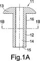
最初に図1A〜図1Nに示された方法を参照すると、図1A及び図1Bは、使用するブランクを示し、図1Aは図1Bの1A−1A線に沿った軸方向断面図であり、図1Bは図1Aの1B−1B線に沿った横断面図である。(技術製図の実際では一般的であるように、残りの図面のほとんどもそのような対になっており、一方が軸方向断面図であり、他方が横断面図である。読者はこれに慣れているであろうから、各対の図面間の関係についてこれ以上、言及しない。)ブランク11は、(一端部にいわゆる「なべ頭」の形状の)半径方向拡大頭部13を備えた細長い管状胴部壁12を有する。ブランクは、その全長にわたって延在する円筒形内孔14を有し、それによって内部管状壁面15を提供する。管状壁12は、円筒形外側表面壁16を有する。
Referring first to the method shown in FIGS. 1A-1N, FIGS. 1A and 1B show the blank used, and FIG. 1A is an axial cross-sectional view along
内孔14及び/または壁12及び15がトライラウンジュラー形状(tri-roundular)または六角形などの他の筒形状でもよいことに留意されたい。
Note that the
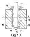
ブランクの内側壁面15は、内孔14内に締まりばめされた円筒形支持ピン17(図1C及び図1D)上に支持されている。
The
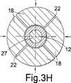
管状壁12の外側に、割型の形をした4つの外側型部材18が設けられている。ブランクをそれらの間に挿入して、(図1Cに示されているように)頭部13の下側が部材18の1組の端部面に当接するようにし、型部材18の他端部はブランクの管状壁12の尾端部を越えて突出する。各部材18の、胴部12の外壁16の方に面する内面に溝19が付けられている。部材18は、最初はわずかに間隔をおいて離れて空間21を形成し、図1C及び図1Dに示されているように、その空間内にブランクの胴部壁12を遊挿することができる。隣接した型部材18間に半径方向隙間22がある。
Four
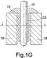
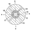
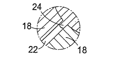
次に、図1E及び図1Fに示されているように、4つの型部材18を、図1Fに矢印Aで示されている方向に支持ピン17に向けて半径方向内向きに押し進めることにより、ブランクの管状壁12を半径方向に絞る。型部材の溝付き面がブランクの管状胴部壁12の外側壁面16に係合し、それによってそれを変形させる。ブランクの内壁15は、剛直な支持ピン17との接触により、半径方向内向きの移動が防止される。胴部壁12の半径方向外側部分が変形し、それにより、それの形状が型部材18の溝19の形状に対してほぼ相補的になって、管状胴部の外側表面壁16に円周溝23が形成される(図1Gを参照)。図1Fに示されているように、4つの型部材18は、それぞれすぐ隣の部材との間に狭められた半径方向隙間22が残る程度まで、閉じ合わせられるだけである。これらの隙間は、ブランク上に形成されたねじ山から半径方向外向きに突出する突起24を収容すると共にそれらの形成を助ける。これらは、管状壁12の金属に対する絞り作用によって発生し、図1Fに示されている。それらは、(図1Fの表示部分の拡大図である)図1Mに、さらに図1FのX−X線に沿った拡大部分断面図である図1Lにも拡大して示されている。突起24は、ブランクの壁上の溝23の谷部分内に形成されて、溝の山部分をわずかに越えるまで半径方向外向きに延出する。突起24が溝23の山部分を越えて延出する必要はないことは、理解されるであろう。
Next, as shown in FIGS. 1E and 1F, the four
代替の配置構成が図1Nに示されており、この図は図1Mに対応する拡大図である。この代替例では、各型18の側壁がさらに離れており、そのため、ブランク上の溝23が完全に形成されたとき、図1Nに示されているように、型18の隣接壁が互いに接触している。しかし、突起24を収容するために、適当な空間25が型の溝付き面に隣接して残される。
An alternative arrangement is shown in FIG. 1N, which is an enlarged view corresponding to FIG. 1M. In this alternative, the sidewalls of each
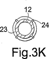
次に、図1G及び図1Hに示されているように、4つの型を図1Hに矢印Bで示された方向に再び引き離す。これにより、管状胴部11の外側面上に形成されている溝23が、型部材の溝19との相互係合から解放される。次に、ブランクを担持したまま、支持ピン17を型の間から軸方向に後退させる。次に、ブランクをピンから押し離すことができ、それによって図1J及び図1Kに示されたような成形済みブランクが残る。
Next, as shown in FIGS. 1G and 1H, the four molds are pulled apart again in the direction indicated by arrow B in FIG. 1H. As a result, the
この段階で「ブランク」という用語は、一貫性及び利便性のために使用される。この段階では、管状締結具が完全に製造されているであろう。代替として、溝付きブランクにさらなる製造段階を、たとえば、熱処理及び/または表面処理を加えてもよい。 At this stage, the term “blank” is used for consistency and convenience. At this stage, the tubular fastener will be fully manufactured. Alternatively, further manufacturing steps may be added to the fluted blank, for example heat treatment and / or surface treatment.
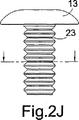
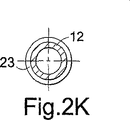
本発明に従った方法の第2例が、図2A〜図2Kに示されており、これらは、前述したように、それぞれ図1A〜図1Kに対応し、同様の部品が同様の参照番号で表されている。この第2方法は、全体的に第1方法に類似しており、それの変更形として見なされるであろう。したがって、第2方法は、第1方法と異なる部分についてだけ詳細に説明することにする。 A second example of a method according to the present invention is shown in FIGS. 2A-2K, which correspond to FIGS. 1A-1K, respectively, as described above, like parts with like reference numerals. It is represented. This second method is generally similar to the first method and will be considered as a modification thereof. Therefore, the second method will be described in detail only for parts different from the first method.
図2Aに示されているように、ブランク11の頭部13に座ぐり穴26が形成されている。支持ピン17の端面34(図2C)がエキスパンダピン36の端面35と接しており、エキスパンダピン36は、円錐形先細部分28によって支持ピンの直径に一致する大径のエキスパンダ部分27を備えている。4つの型18は最初、それらの側面間に半径方向の隙間がまったくないように閉じ合わされ、また、図2C及び図2Dに示されているように、それらの半径方向内側の溝付き表面は、ブランクの管状胴部壁12の外壁16との間に小さい隙間を生じる。次に、支持ピン17をブランクに対して、ブランクの頭部13に向かう方向に、すなわち、図2Cにおいて上方に引っ張る。先細部分28が、それからエキスパンダ部分27が徐々にブランクの内孔14に入る。ブランクは、ブランク頭部13と接触して反力を吸収する支持工具29によって、軸方向上向きの移動が防止される。これにより、管状胴部壁12が半径方向に拡張し、それによって、その外側部分が型部材内の溝19に絞り込まれ、このようにして管状壁内に外側円周溝が形成される。ブランクの頭部13内の座ぐり穴26がエキスパンダ部分27を収容し、それにより、頭部13は半径方向に拡張されない。これは、図2E及び図2Fに示された位置である。型18の間に半径方向隙間がまったくないので、ブランクの溝付き外面からの突起が形成されない。次に、図2G及び図2Hに示されているように、型18を半径方向に後退させて、外側溝付きブランクをエキスパンダ部分27から押し離して、それにより、図2J及び図2Kに示されている結果が得られる。前述した第1方法の場合のように、型の間に半径方向隙間を残すことによって、突起を形成してもよい。
As shown in FIG. 2A, a
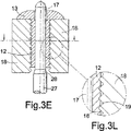
図3A〜図3Mに示された第3例の方法は、外側型表面の係合の直径の有効減少及び内側支持体の係合の直径の増加を組み合わせている点で、最初の2つの方法の特徴を組み合わせたものと見なすことができる。 The third example method shown in FIGS. 3A-3M combines the first two methods in that it combines an effective decrease in outer mold surface engagement diameter and an increase in inner support engagement diameter. It can be regarded as a combination of the features.
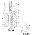
図3A及び図3Bに示されているように、ブランク11は、図2A及び図2Bに示されて第2例の方法に使用されたものと同一である。同様に、支持ピン17は、先細部分28によって拡大直径のエキスパンダ位置27に結合されている。図3C及び図3Dに示されているように、まず、ブランクを支持ピン17にはめて、型18の溝付き内壁間に挿入する。次に、型を半径方向内向きに、図3E及び図3Fに示された位置まで前進させ、この位置では、図3E及び図3Fに、また、さらに明らかには図3Lに拡大して示されているように、型の溝間の隆起部分が外側表面壁16に部分的に入っている。胴部壁12は、支持ピン17によって内側変形を生じないように支持されている。次に、ブランクの頭部13と接触している支持工具29の反動に逆らって、支持ピン17を軸方向上方に管状ブランク内へ押し込み、それにより、エキスパンダ部分27が管状壁12の内孔に入って、それを半径方向に拡張させる。これにより、図3G及び図3Hに示されているように、壁材料の外側部分が型の溝に押し込まれる。図3Mに示されているように、材料は型の溝を完全には満たさなくてもよい。
As shown in FIGS. 3A and 3B, the blank 11 is the same as that shown in FIGS. 2A and 2B and used in the method of the second example. Similarly, the
次に、型を半径方向に後退させて、ブランクとの係合を解除し、次にブランクをエキスパンダ部分27から押し離して、それにより、図3J及び図3Kに示されている結果が得られる。図3Hに示されているように、型18が合わされているとき、その間に半径方向隙間22が存在し、そのため、図3J及び図3Kに示されているように、突起24が押し出される。
The mold is then retracted radially to disengage the blank, and then the blank is pushed away from the
以上の例において、ブランクの材料は、マグネシウムを2.5%含有するアルミニウム5052である。形成後の管状胴部すなわち軸部の長さが7.0mm、その外径が3.4mm、その内孔の内径が1.6mm、頭部の直径が6.0mm、頭部の厚さが0.9mmである。他の材料及び/または寸法を使用してもよいことに留意されたい。 In the above example, the blank material is aluminum 5052 containing 2.5% magnesium. The length of the tubular body after the formation, that is, the shaft portion is 7.0 mm, the outer diameter is 3.4 mm, the inner diameter of the inner hole is 1.6 mm, the head diameter is 6.0 mm, and the head thickness is 0.9 mm. Note that other materials and / or dimensions may be used.
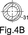
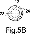
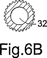
本発明は、上記例の詳細に制限されない。たとえば、型部材18の内面に適当な形の溝19を設けることによって、その他の所望形状の外側溝をブランクの外側管状壁に形成してもよい。このため、図4A及び図4Bは、らせん溝31を有する締結具を示し、この溝31はねじ山を与える(これは、互いに結合されて、らせん溝を形成する多数の円周または近似円周溝を有すると見なすことができるであろう)。ねじ部分の一端部または両端部にねじ山のない部分33を設けてもよい。上記第1例の方法によってそのようならせんねじを形成した場合、半径方向突起が形成されて、それらが据え付け済み締結具の緩みに対する抵抗性を与えるであろう。これは、図5A及び図5Bに示されている。図6A及び図6Bは、長手方向溝32を有する締結具を示す。本発明の方法は、上記及び他のすべての形状の溝を有する管状締結具を形成できるようにする。
The present invention is not limited to the details of the above examples. For example, by providing a
Claims (7)
前記管状締結具は、前記外溝から半径方向外側に突出する複数の突起を有しており、
前記方法は、
管状壁を有する適当な管状ブランク、
前記管状ブランクの内側管状壁面に係合する外周面を備えた内側部材、及び
前記管状ブランクの外側管状壁面に係合する適当な形状の内周面を備えた複数の外側部材
を設けるステップと、
前記内側部材と前記複数の外側部材との間で、前記管状ブランクの前記管状壁を絞るステップと、
を含み、
それにより、前記管状ブランクの前記外側管状壁面上に前記外溝を形成し、
前記管状壁を絞る前記ステップは、前記内側部材の前記外周面と、前記複数の外側部材の前記内周面との間の距離を減少させることによって達成され、
前記複数の外側部材は、
前記複数の外側部材の前記内周面が、前記管状ブランクの前記外側管状壁面に接触するように、且つ
互いに隣り合う前記外側部材の隣接壁同士が、前記隣接壁同士の間に空間を残しつつ接触するように
前記管状ブランクまで閉じられることにより、前記突起を収容し、
それにより、前記管状ブランクの前記外側管状壁面の、互いに隣り合う前記外側部材間の前記空間内に、前記複数の突起が形成される、方法。A method of forming a radially expandable outer grooved tubular fastener from metal comprising:
The tubular fastener has a plurality of protrusions protruding radially outward from the outer groove,
The method
A suitable tubular blank having a tubular wall,
Providing an inner member with an outer peripheral surface that engages with an inner tubular wall surface of the tubular blank, and a plurality of outer members with an appropriately shaped inner peripheral surface that engages with an outer tubular wall surface of the tubular blank;
Squeezing the tubular wall of the tubular blank between the inner member and the plurality of outer members;
Including
Thereby, the outer groove is formed on the outer tubular wall of the tubular blank,
The step of squeezing the tubular wall is accomplished by reducing a distance between the outer peripheral surface of the inner member and the inner peripheral surfaces of the plurality of outer members;
The plurality of outer members are:
The adjacent walls of the outer members adjacent to each other leave a space between the adjacent walls such that the inner peripheral surfaces of the plurality of outer members are in contact with the outer tubular wall surface of the tubular blank. To touch
By closing to the tubular blank, the projection is received,
Thereby, the outer tubular wall surface of the front Symbol tubular blanks, in the space between the outer member adjacent to each other, said plurality of projections are formed, the method.
前記内側部材が、前記管状ブランクの前記管状壁を径方向に拡張させること、及び
前記複数の外側部材を、前記内側部材に向かって押し進めること
の一方または両方によって達成される、請求項1に記載の方法。The step of squeezing the tubular wall comprises:
2. The inner member is achieved by one or both of radially expanding the tubular wall of the tubular blank and pushing the plurality of outer members toward the inner member. the method of.
前記内側部材は、増加する直径で前記管状ブランクの前記内側管状壁面に係合し、それによって前記溝の形成を助ける、請求項2に記載の方法。The outer member is initially gradually closed to the outer tubular wall surface of the tubular blank, thereby engaging the outer tubular wall surface and at least partially forming the groove in the outer tubular wall surface;
The method of claim 2, wherein the inner member engages the inner tubular wall surface of the tubular blank with increasing diameter, thereby assisting in the formation of the groove.
Applications Claiming Priority (2)
| Application Number | Priority Date | Filing Date | Title |
|---|---|---|---|
| GB0214959A GB2390047B (en) | 2002-06-28 | 2002-06-28 | Split die groove maker |
| PCT/GB2003/001619 WO2004002652A1 (en) | 2002-06-28 | 2003-04-15 | Split die for forming grooved workpieces |
Publications (2)
| Publication Number | Publication Date |
|---|---|
| JP2005531413A JP2005531413A (en) | 2005-10-20 |
| JP4445385B2 true JP4445385B2 (en) | 2010-04-07 |
Family
ID=9939461
Family Applications (1)
| Application Number | Title | Priority Date | Filing Date |
|---|---|---|---|
| JP2004516906A Expired - Fee Related JP4445385B2 (en) | 2002-06-28 | 2003-04-15 | Method for forming a grooved workpiece |
Country Status (16)
| Country | Link |
|---|---|
| US (1) | US7237424B2 (en) |
| EP (1) | EP1572393B1 (en) |
| JP (1) | JP4445385B2 (en) |
| KR (2) | KR100882981B1 (en) |
| CN (1) | CN1214875C (en) |
| AT (1) | ATE417685T1 (en) |
| AU (1) | AU2003224282B2 (en) |
| BR (1) | BR0312056A (en) |
| CA (1) | CA2490300C (en) |
| DE (1) | DE60325414D1 (en) |
| ES (1) | ES2316747T3 (en) |
| GB (1) | GB2390047B (en) |
| MX (1) | MXPA04012811A (en) |
| PL (1) | PL374093A1 (en) |
| TW (1) | TWI221789B (en) |
| WO (1) | WO2004002652A1 (en) |
Families Citing this family (17)
| Publication number | Priority date | Publication date | Assignee | Title |
|---|---|---|---|---|
| US7055237B2 (en) * | 2003-09-29 | 2006-06-06 | Medtronic Vascular, Inc. | Method of forming a drug eluting stent |
| DE102005026883A1 (en) * | 2005-06-10 | 2006-12-14 | Ejot Gmbh & Co. Kg | Hollow pin provided with a longitudinal bore |
| AU2009205896A1 (en) | 2008-01-17 | 2009-07-23 | Synthes Gmbh | An expandable intervertebral implant and associated method of manufacturing the same |
| DE102008038185B3 (en) * | 2008-08-19 | 2010-01-28 | Sieber Forming Solutions Gmbh | Method and device for the production of fastening or connecting means with radial outer contours, in particular screws or threaded bolts |
| KR20110084215A (en) * | 2008-10-03 | 2011-07-21 | 지베르 포밍 솔류션 게엠바하 | Method and device for the non-cutting production of an outside thread on hollow metal work pieces |
| JP5907458B2 (en) | 2009-07-06 | 2016-04-26 | ジンテス ゲゼルシャフト ミット ベシュレンクテル ハフツング | Expandable fixation assembly |
| US8979860B2 (en) | 2010-06-24 | 2015-03-17 | DePuy Synthes Products. LLC | Enhanced cage insertion device |
| TWI400599B (en) * | 2010-08-05 | 2013-07-01 | Asia Vital Components Co Ltd | Radiative fin manufacturing method |
| DE102011018465A1 (en) * | 2011-04-21 | 2012-10-25 | Labomatic Instruments Ag | Tightening tool for a screw element with a tool holder and an associated line and coupling part and screw element |
| DE102012103179A1 (en) * | 2012-04-12 | 2013-10-17 | Sieber Forming Solutions Gmbh | Method and device for chipless production of an external thread on workpieces made of metal |
| US9694526B2 (en) | 2013-03-15 | 2017-07-04 | Apple Inc. | Injection mold with multi-axial core inserts |
| US9475109B2 (en) | 2013-12-31 | 2016-10-25 | Simpson Strong-Tie Company, Inc. | Method of manufacturing a hollow externally threaded fastener |
| ES2928258T3 (en) * | 2014-07-07 | 2022-11-16 | Physical Systems | Hollow metal screw and manufacturing method |
| JP7043870B2 (en) * | 2017-02-16 | 2022-03-30 | 大川精螺工業株式会社 | Manufacturing equipment for manufacturing nipples |
| CN106956110A (en) * | 2017-04-21 | 2017-07-18 | 绵竹市凯瑞机械加工有限公司 | A kind of processing method of hexagon socket head cap screw |
| US10940016B2 (en) | 2017-07-05 | 2021-03-09 | Medos International Sarl | Expandable intervertebral fusion cage |
| DE102019208854A1 (en) * | 2019-06-18 | 2020-12-24 | Contitech Kühner Gmbh & Cie. Kg | Method and device for producing a hose nipple |
Family Cites Families (20)
| Publication number | Priority date | Publication date | Assignee | Title |
|---|---|---|---|---|
| US687464A (en) * | 1901-08-05 | 1901-11-26 | William E Sullivan | Die for making screw-threads on tubes. |
| US2856617A (en) * | 1956-04-17 | 1958-10-21 | Nat Machine Products Company | Method of making self-locking valve lash adjusting screws |
| FR82239E (en) * | 1962-09-05 | 1964-01-10 | Pipe threading process by deformation of the material | |
| US3424212A (en) * | 1967-04-12 | 1969-01-28 | United Co The | Screw wrench device |
| DE2114311C3 (en) * | 1970-04-10 | 1974-09-26 | N.V. Philips' Gloeilampenfabrieken, Eindhoven (Niederlande) | Method for adjusting the color purity in a color display tube and arrangement for carrying out the method |
| FR2176236A5 (en) * | 1972-03-15 | 1973-10-26 | Gemmer France | |
| US4335479A (en) * | 1978-05-23 | 1982-06-22 | Celus Fasteners Manufacturing, Inc. | Method and apparatus for making blind rivets |
| NL7901892A (en) * | 1979-03-08 | 1980-09-10 | Erico Europa | Forming self locking screw thread in tube - by cold forging on hollow former, unscrewing it after reducing temp. or internal pressure |
| DE3245055C2 (en) * | 1982-12-06 | 1985-05-30 | Daimler-Benz Ag, 7000 Stuttgart | Blind rivet |
| GB8315077D0 (en) * | 1983-06-01 | 1983-07-06 | Avdel Ltd | Threaded fastener |
| US4869629A (en) * | 1988-07-22 | 1989-09-26 | Textron Inc. | Blind fastener |
| US5199751A (en) * | 1990-11-13 | 1993-04-06 | Dana Corporation | Pressure hose coupling collar and method for producing same |
| GB9104706D0 (en) * | 1991-03-06 | 1991-04-17 | Emhart Inc | Production of rivet-nuts |
| DE9113338U1 (en) * | 1991-10-26 | 1993-03-04 | Gebrüder Welger GmbH & Co KG, 38304 Wolfenbüttel | Device for producing longitudinal ribs in the wall of a cylindrical tube |
| JP3204331B2 (en) * | 1992-05-15 | 2001-09-04 | 光洋精工株式会社 | Method and apparatus for forging parts having grooves on the outer periphery of cylindrical body |
| DE4321174A1 (en) * | 1993-06-25 | 1995-01-05 | Schruff Herberts | Method for producing an upsetting sleeve and upsetting sleeve produced by the method |
| JP2860472B2 (en) * | 1996-07-24 | 1999-02-24 | 共英製鋼株式会社 | Anchor bolt and method of manufacturing the same |
| FR2755042B1 (en) * | 1996-10-24 | 1998-12-24 | Lemforder Nacam Sa | PROCESS FOR OBTAINING SPLINES ON A TREE |
| JP2000202567A (en) * | 1999-01-13 | 2000-07-25 | Toto Ltd | Male-screw and forge-formation thereof |
| US6178802B1 (en) * | 1999-04-13 | 2001-01-30 | The Gates Corporation | Slotted crimping die for use in a crimping machine |
-
2002
- 2002-06-28 GB GB0214959A patent/GB2390047B/en not_active Expired - Fee Related
- 2002-09-27 CN CNB021439087A patent/CN1214875C/en not_active Expired - Fee Related
- 2002-10-28 TW TW091132023A patent/TWI221789B/en not_active IP Right Cessation
-
2003
- 2003-04-15 KR KR1020047021368A patent/KR100882981B1/en not_active IP Right Cessation
- 2003-04-15 ES ES03720706T patent/ES2316747T3/en not_active Expired - Lifetime
- 2003-04-15 JP JP2004516906A patent/JP4445385B2/en not_active Expired - Fee Related
- 2003-04-15 AT AT03720706T patent/ATE417685T1/en not_active IP Right Cessation
- 2003-04-15 KR KR1020087027722A patent/KR100889901B1/en not_active IP Right Cessation
- 2003-04-15 MX MXPA04012811A patent/MXPA04012811A/en active IP Right Grant
- 2003-04-15 US US10/517,715 patent/US7237424B2/en not_active Expired - Fee Related
- 2003-04-15 AU AU2003224282A patent/AU2003224282B2/en not_active Ceased
- 2003-04-15 CA CA002490300A patent/CA2490300C/en not_active Expired - Fee Related
- 2003-04-15 PL PL03374093A patent/PL374093A1/en unknown
- 2003-04-15 BR BR0312056-2A patent/BR0312056A/en not_active Application Discontinuation
- 2003-04-15 WO PCT/GB2003/001619 patent/WO2004002652A1/en active Application Filing
- 2003-04-15 EP EP03720706A patent/EP1572393B1/en not_active Expired - Lifetime
- 2003-04-15 DE DE60325414T patent/DE60325414D1/en not_active Expired - Lifetime
Also Published As
| Publication number | Publication date |
|---|---|
| JP2005531413A (en) | 2005-10-20 |
| AU2003224282A1 (en) | 2004-01-19 |
| GB2390047A (en) | 2003-12-31 |
| TW200300104A (en) | 2003-05-16 |
| US7237424B2 (en) | 2007-07-03 |
| WO2004002652A1 (en) | 2004-01-08 |
| KR20050058295A (en) | 2005-06-16 |
| CA2490300C (en) | 2008-09-16 |
| GB0214959D0 (en) | 2002-08-07 |
| PL374093A1 (en) | 2005-09-19 |
| ES2316747T3 (en) | 2009-04-16 |
| AU2003224282B2 (en) | 2009-01-29 |
| CN1214875C (en) | 2005-08-17 |
| KR100882981B1 (en) | 2009-02-12 |
| ATE417685T1 (en) | 2009-01-15 |
| GB2390047B (en) | 2005-05-11 |
| MXPA04012811A (en) | 2005-03-31 |
| US20050233813A1 (en) | 2005-10-20 |
| DE60325414D1 (en) | 2009-01-29 |
| CN1404936A (en) | 2003-03-26 |
| CA2490300A1 (en) | 2004-01-08 |
| KR100889901B1 (en) | 2009-03-20 |
| EP1572393A1 (en) | 2005-09-14 |
| BR0312056A (en) | 2005-03-29 |
| KR20080104081A (en) | 2008-11-28 |
| TWI221789B (en) | 2004-10-11 |
| EP1572393B1 (en) | 2008-12-17 |
Similar Documents
| Publication | Publication Date | Title |
|---|---|---|
| JP4445385B2 (en) | Method for forming a grooved workpiece | |
| JP4037613B2 (en) | Method for manufacturing tubular member | |
| US3491649A (en) | Rivets | |
| CZ280550B6 (en) | Metallic expansion bolt and process for producing thereof | |
| US3837208A (en) | Method and apparatus for blind riveting | |
| US6854940B2 (en) | Closed-end blind rivet with a crimped shank and method of manufacture thereof | |
| US2887694A (en) | Method of forming expandable end blind rivets | |
| WO1988007140A1 (en) | Blind rivet assembly with buckle sleeve | |
| KR950033134A (en) | Blind rivets | |
| JPH0767591B2 (en) | Tool for producing hollow article and method for producing the same | |
| US6857962B2 (en) | Blind threaded fastener forming technique | |
| JP2007177886A (en) | Expansion type fastener | |
| JP2005007426A (en) | Shaping unit for shaft-shaped component | |
| KR102127681B1 (en) | Expandable Anchor Bolt | |
| JP4936148B2 (en) | Insert metal fitting and manufacturing method thereof | |
| JP3084793U (en) | Anchor bolt | |
| JP3188218B2 (en) | Method and apparatus for manufacturing anchor sleeve | |
| JP2004230421A (en) | Anchor sleeve for concrete, and its manufacturing method | |
| US3329458A (en) | Integral heavy duty door knob | |
| US20030060296A1 (en) | Method of manufacturing an expansion sleeve | |
| JPH0617811A (en) | Manufacture of anchor for concrete | |
| JP2009208113A (en) | Method for forming hollow-stepped shaft |
Legal Events
| Date | Code | Title | Description |
|---|---|---|---|
| A131 | Notification of reasons for refusal |
Free format text: JAPANESE INTERMEDIATE CODE: A131 Effective date: 20070828 |
|
| A601 | Written request for extension of time |
Free format text: JAPANESE INTERMEDIATE CODE: A601 Effective date: 20071128 |
|
| A602 | Written permission of extension of time |
Free format text: JAPANESE INTERMEDIATE CODE: A602 Effective date: 20071207 |
|
| A601 | Written request for extension of time |
Free format text: JAPANESE INTERMEDIATE CODE: A601 Effective date: 20071228 |
|
| A602 | Written permission of extension of time |
Free format text: JAPANESE INTERMEDIATE CODE: A602 Effective date: 20080116 |
|
| A521 | Request for written amendment filed |
Free format text: JAPANESE INTERMEDIATE CODE: A523 Effective date: 20080125 |
|
| A131 | Notification of reasons for refusal |
Free format text: JAPANESE INTERMEDIATE CODE: A131 Effective date: 20090507 |
|
| A601 | Written request for extension of time |
Free format text: JAPANESE INTERMEDIATE CODE: A601 Effective date: 20090806 |
|
| A602 | Written permission of extension of time |
Free format text: JAPANESE INTERMEDIATE CODE: A602 Effective date: 20090813 |
|
| A601 | Written request for extension of time |
Free format text: JAPANESE INTERMEDIATE CODE: A601 Effective date: 20090907 |
|
| A602 | Written permission of extension of time |
Free format text: JAPANESE INTERMEDIATE CODE: A602 Effective date: 20090914 |
|
| A521 | Request for written amendment filed |
Free format text: JAPANESE INTERMEDIATE CODE: A523 Effective date: 20091006 |
|
| TRDD | Decision of grant or rejection written | ||
| A01 | Written decision to grant a patent or to grant a registration (utility model) |
Free format text: JAPANESE INTERMEDIATE CODE: A01 Effective date: 20100105 |
|
| A01 | Written decision to grant a patent or to grant a registration (utility model) |
Free format text: JAPANESE INTERMEDIATE CODE: A01 |
|
| A61 | First payment of annual fees (during grant procedure) |
Free format text: JAPANESE INTERMEDIATE CODE: A61 Effective date: 20100115 |
|
| R150 | Certificate of patent or registration of utility model |
Free format text: JAPANESE INTERMEDIATE CODE: R150 |
|
| FPAY | Renewal fee payment (event date is renewal date of database) |
Free format text: PAYMENT UNTIL: 20130122 Year of fee payment: 3 |
|
| FPAY | Renewal fee payment (event date is renewal date of database) |
Free format text: PAYMENT UNTIL: 20140122 Year of fee payment: 4 |
|
| R250 | Receipt of annual fees |
Free format text: JAPANESE INTERMEDIATE CODE: R250 |
|
| R250 | Receipt of annual fees |
Free format text: JAPANESE INTERMEDIATE CODE: R250 |
|
| R250 | Receipt of annual fees |
Free format text: JAPANESE INTERMEDIATE CODE: R250 |
|
| LAPS | Cancellation because of no payment of annual fees |