JP4444790B2 - Image compression method, image compression apparatus, image compression system, and program - Google Patents
Image compression method, image compression apparatus, image compression system, and program Download PDFInfo
- Publication number
- JP4444790B2 JP4444790B2 JP2004318271A JP2004318271A JP4444790B2 JP 4444790 B2 JP4444790 B2 JP 4444790B2 JP 2004318271 A JP2004318271 A JP 2004318271A JP 2004318271 A JP2004318271 A JP 2004318271A JP 4444790 B2 JP4444790 B2 JP 4444790B2
- Authority
- JP
- Japan
- Prior art keywords
- encoding
- block
- image
- bits
- current
- Prior art date
- Legal status (The legal status is an assumption and is not a legal conclusion. Google has not performed a legal analysis and makes no representation as to the accuracy of the status listed.)
- Expired - Fee Related
Links
Images


Classifications
-
- H—ELECTRICITY
- H04—ELECTRIC COMMUNICATION TECHNIQUE
- H04N—PICTORIAL COMMUNICATION, e.g. TELEVISION
- H04N19/00—Methods or arrangements for coding, decoding, compressing or decompressing digital video signals
- H04N19/10—Methods or arrangements for coding, decoding, compressing or decompressing digital video signals using adaptive coding
- H04N19/102—Methods or arrangements for coding, decoding, compressing or decompressing digital video signals using adaptive coding characterised by the element, parameter or selection affected or controlled by the adaptive coding
- H04N19/117—Filters, e.g. for pre-processing or post-processing
-
- H—ELECTRICITY
- H04—ELECTRIC COMMUNICATION TECHNIQUE
- H04N—PICTORIAL COMMUNICATION, e.g. TELEVISION
- H04N19/00—Methods or arrangements for coding, decoding, compressing or decompressing digital video signals
- H04N19/10—Methods or arrangements for coding, decoding, compressing or decompressing digital video signals using adaptive coding
- H04N19/134—Methods or arrangements for coding, decoding, compressing or decompressing digital video signals using adaptive coding characterised by the element, parameter or criterion affecting or controlling the adaptive coding
- H04N19/146—Data rate or code amount at the encoder output
- H04N19/147—Data rate or code amount at the encoder output according to rate distortion criteria
-
- H—ELECTRICITY
- H04—ELECTRIC COMMUNICATION TECHNIQUE
- H04N—PICTORIAL COMMUNICATION, e.g. TELEVISION
- H04N19/00—Methods or arrangements for coding, decoding, compressing or decompressing digital video signals
- H04N19/10—Methods or arrangements for coding, decoding, compressing or decompressing digital video signals using adaptive coding
- H04N19/169—Methods or arrangements for coding, decoding, compressing or decompressing digital video signals using adaptive coding characterised by the coding unit, i.e. the structural portion or semantic portion of the video signal being the object or the subject of the adaptive coding
- H04N19/17—Methods or arrangements for coding, decoding, compressing or decompressing digital video signals using adaptive coding characterised by the coding unit, i.e. the structural portion or semantic portion of the video signal being the object or the subject of the adaptive coding the unit being an image region, e.g. an object
- H04N19/176—Methods or arrangements for coding, decoding, compressing or decompressing digital video signals using adaptive coding characterised by the coding unit, i.e. the structural portion or semantic portion of the video signal being the object or the subject of the adaptive coding the unit being an image region, e.g. an object the region being a block, e.g. a macroblock
-
- H—ELECTRICITY
- H04—ELECTRIC COMMUNICATION TECHNIQUE
- H04N—PICTORIAL COMMUNICATION, e.g. TELEVISION
- H04N19/00—Methods or arrangements for coding, decoding, compressing or decompressing digital video signals
- H04N19/10—Methods or arrangements for coding, decoding, compressing or decompressing digital video signals using adaptive coding
- H04N19/169—Methods or arrangements for coding, decoding, compressing or decompressing digital video signals using adaptive coding characterised by the coding unit, i.e. the structural portion or semantic portion of the video signal being the object or the subject of the adaptive coding
- H04N19/186—Methods or arrangements for coding, decoding, compressing or decompressing digital video signals using adaptive coding characterised by the coding unit, i.e. the structural portion or semantic portion of the video signal being the object or the subject of the adaptive coding the unit being a colour or a chrominance component
-
- H—ELECTRICITY
- H04—ELECTRIC COMMUNICATION TECHNIQUE
- H04N—PICTORIAL COMMUNICATION, e.g. TELEVISION
- H04N19/00—Methods or arrangements for coding, decoding, compressing or decompressing digital video signals
- H04N19/10—Methods or arrangements for coding, decoding, compressing or decompressing digital video signals using adaptive coding
- H04N19/189—Methods or arrangements for coding, decoding, compressing or decompressing digital video signals using adaptive coding characterised by the adaptation method, adaptation tool or adaptation type used for the adaptive coding
- H04N19/192—Methods or arrangements for coding, decoding, compressing or decompressing digital video signals using adaptive coding characterised by the adaptation method, adaptation tool or adaptation type used for the adaptive coding the adaptation method, adaptation tool or adaptation type being iterative or recursive
-
- H—ELECTRICITY
- H04—ELECTRIC COMMUNICATION TECHNIQUE
- H04N—PICTORIAL COMMUNICATION, e.g. TELEVISION
- H04N19/00—Methods or arrangements for coding, decoding, compressing or decompressing digital video signals
- H04N19/60—Methods or arrangements for coding, decoding, compressing or decompressing digital video signals using transform coding
- H04N19/63—Methods or arrangements for coding, decoding, compressing or decompressing digital video signals using transform coding using sub-band based transform, e.g. wavelets
-
- H—ELECTRICITY
- H04—ELECTRIC COMMUNICATION TECHNIQUE
- H04N—PICTORIAL COMMUNICATION, e.g. TELEVISION
- H04N19/00—Methods or arrangements for coding, decoding, compressing or decompressing digital video signals
- H04N19/10—Methods or arrangements for coding, decoding, compressing or decompressing digital video signals using adaptive coding
- H04N19/102—Methods or arrangements for coding, decoding, compressing or decompressing digital video signals using adaptive coding characterised by the element, parameter or selection affected or controlled by the adaptive coding
- H04N19/115—Selection of the code volume for a coding unit prior to coding
-
- H—ELECTRICITY
- H04—ELECTRIC COMMUNICATION TECHNIQUE
- H04N—PICTORIAL COMMUNICATION, e.g. TELEVISION
- H04N19/00—Methods or arrangements for coding, decoding, compressing or decompressing digital video signals
- H04N19/10—Methods or arrangements for coding, decoding, compressing or decompressing digital video signals using adaptive coding
- H04N19/134—Methods or arrangements for coding, decoding, compressing or decompressing digital video signals using adaptive coding characterised by the element, parameter or criterion affecting or controlling the adaptive coding
- H04N19/146—Data rate or code amount at the encoder output
Description
本発明はデジタルビデオ圧縮の分野に関する。特に、本発明は、ビデオフレームのシーケンスを符号化する方法及びビデオ符号化アプリケーションにおける速度制御に関する。本発明は、更に、ビデオフレームのシーケンスを符号化するための装置及びコンピュータプログラムに関する。 The present invention relates to the field of digital video compression. In particular, the present invention relates to a method for encoding a sequence of video frames and rate control in a video encoding application. The invention further relates to an apparatus and a computer program for encoding a sequence of video frames.
デジタル画像及びデジタルビデオは、汎用コンピュータ、デジタルスチルカメラ及びデジタルビデオカメラを含めた数多くの装置に格納され、使用される。格納、メモリ及び帯域幅のコストを低減するために、デジタル画像及びデジタルビデオは、通常、圧縮形態で装置に格納される。広く使用されている画像圧縮の規格は「Joint Photographic Experts Group」、すなわち、JPEG規格である。画像圧縮に関する発展段階の新たな規格はJPEG2000規格である。JPEG及びJPEG2000は共に名目上は静止画像圧縮規格である。JPEGは主に静止画像を圧縮するために使用されるが、大まかに「モーションJPEG」として知られる様々なビデオ符号化フォーマットがある。モーションJPEGはJPEGを使用してビデオの各フレームを静止画像として符号化し、ビデオの全ての符号化フレームをモーションJPEG符号化ストリームにラッピングするための圧縮ビデオストリームフォーマットを提供する。しかし、モーションJPEGは正式に規格化されたわけではない。現在、JPEG2000規格は、JPEG2000Final Committee Draft Version1.0、2000年3月16日、ISO/IEC FCD15444‐1(第I部)及びJPEG2000Final Committee Draft、2000年12月7日、ISO/IEC FCD15444‐2(第II部)の2つの刊行物に記載されている静止画像圧縮モードを規定している。また、JPEG2000規格は、MotionJPEG2000Final Committee Draft 1.0、2001年3月14日、ISO/IEC FCD15444‐3(第III部)に記載された、モーションJPEG2000として知られるビデオ符号化モードを規定している。モーションJPEG2000は、ビデオの個々のフレームがJPEG2000によって(静止画像モードで)符号化され、その結果得られる圧縮フレームが圧縮ビデオストリーム(例えば、ファイルフォーマット)にラッピングされるという点で、モーションJPEGに類似している。潜在的にはJPEGモーショングループ(モーションJPEG又はモーションJPEG2000)より良好な圧縮を提供しうる、MPEGグループなどの他のビデオ符号化フォーマットも存在しているが、JPEGモーショングループはいくつかの異なる利点を提供する。加えて、モーションJPEG2000は静止画像モードにおけるJPEG2000に由来する一連の特徴を提供する。 Digital images and digital video are stored and used in many devices, including general purpose computers, digital still cameras, and digital video cameras. To reduce storage, memory and bandwidth costs, digital images and digital video are typically stored in the device in a compressed form. A widely used image compression standard is the “Joint Photographic Experts Group”, ie, the JPEG standard. A new standard in the development stage for image compression is the JPEG2000 standard. Both JPEG and JPEG2000 are nominally still image compression standards. JPEG is mainly used to compress still images, but there are various video encoding formats, generally known as “motion JPEG”. Motion JPEG uses JPEG to encode each frame of video as a still image and provides a compressed video stream format for wrapping all encoded frames of video into a motion JPEG encoded stream. However, Motion JPEG has not been officially standardized. Currently, the JPEG2000 standard is based on JPEG2000 Final Committee Draft Version 1.0, March 16, 2000, ISO / IEC FCD154444-1 (Part I) and JPEG2000 Final Committee Draft, December 7, 2000, ISO / IEC FCD154444-2 ( Part II) defines the still image compression mode described in two publications. The JPEG2000 standard also defines a video coding mode known as Motion JPEG2000, described in Motion JPEG2000 Final Committee Draft 1.0, March 14, 2001, ISO / IEC FCD15444-3 (Part III). . Motion JPEG2000 is similar to Motion JPEG in that individual frames of the video are encoded (in still image mode) by JPEG2000 and the resulting compressed frames are wrapped into a compressed video stream (eg, a file format). is doing. There are other video encoding formats such as MPEG groups that could potentially provide better compression than JPEG motion groups (Motion JPEG or Motion JPEG2000), but JPEG motion groups offer several different advantages. provide. In addition, Motion JPEG2000 provides a set of features derived from JPEG2000 in still image mode.
本明細書の説明の便宜上、「JPEG2000」という用語は、静止画像モードではJPEG2000規格、すなわち、静止画像(ビデオの1フレーム)を圧縮/伸張するための規格を表し、ビデオ圧縮/伸張モードのJPEG2000規格に言及する場合には「モーションJPEG2000」(MJ2K)を表すために使用される。 For convenience of description herein, the term “JPEG2000” refers to the JPEG2000 standard in still image mode, ie, a standard for compressing / decompressing still images (one frame of video), and JPEG2000 in video compression / decompression mode. When referring to the standard, it is used to represent “Motion JPEG2000” (MJ2K).
画像又はビデオを圧縮する場合に実行されるべき重要な決定は、圧縮画像及び圧縮ビデオに対してどれほどの数のバイトを利用可能であるかということである。圧縮速度が速くなるほど、格納及び送信に要求されるバイトの数は少なくなる。その妥協点は、圧縮速度が増すにつれて、得られる伸張後の画像又はビデオの画質は一般に低下するということである。1つの目標は、許容しうる画質レベルを維持しつつ圧縮を最大にするか、あるいは一定のバイト数の中で画像又はビデオの画質を最大にすることである。所定の速度で画質を最大にするためにJPEG2000により推奨されている技法は、符号化後速度ひずみ最適化(PVRD−opt)と呼ばれる速度制御戦略を使用する方法である。最適化は、実際の符号化自体は完了しているが、利用可能なバイトバジェットを超過したときに採用される。そこで、例えば、実現可能な最高の画質で所望の目標ビットレートに適合させるように圧縮データをトリムバックする(すなわち、圧縮データの一部を放棄する)ためにPCRD‐optが使用される。JPEG2000により推奨されるPCRD‐optを利用する圧縮方式の1つの問題点は、コードブロックが過剰符号化される、すなわち、必要な数より多くのコーディングパスが生成される場合が多いということである。余りに大きな過剰符号化は圧縮方式を遅延させる。更に、過剰符号化は中間圧縮データをバッファするために要求されるメモリの量を増加させる。 An important decision to be made when compressing an image or video is how many bytes are available for the compressed image and the compressed video. The faster the compression rate, the fewer bytes are required for storage and transmission. The compromise is that as the compression speed increases, the quality of the resulting decompressed image or video generally decreases. One goal is to maximize compression while maintaining an acceptable level of image quality, or to maximize image or video image quality within a fixed number of bytes. A technique recommended by JPEG 2000 to maximize image quality at a given speed is to use a speed control strategy called post-encoding speed distortion optimization (PVRD-opt). Optimization is employed when the actual encoding itself is complete but the available byte budget is exceeded. Thus, for example, PCRD-opt is used to trim back the compressed data (ie, discard some of the compressed data) to match the desired target bit rate with the best possible image quality. One problem with compression schemes that utilize the PCRD-opt recommended by JPEG2000 is that code blocks are over-coded, that is, more coding passes are often generated than necessary. . Too much over-encoding will delay the compression scheme. In addition, overcoding increases the amount of memory required to buffer intermediate compressed data.
速度制御に加えて、画質に影響を及ぼす様々な重要な圧縮システムパラメータがある。例えば、JPEG及びJPEG2000においては、人間の視覚系統に相応する高周波数とは対照的に、低い周波数の重要性を強調するために1組のサブバンド又は係数重みが使用される。JPEG2000では、それらは通常は「視覚重み」と呼ばれる。 In addition to speed control, there are various important compression system parameters that affect image quality. For example, in JPEG and JPEG 2000, a set of subbands or coefficient weights is used to emphasize the importance of low frequencies as opposed to high frequencies corresponding to the human visual system. In JPEG 2000, they are usually called “visual weights”.
ビデオシーケンスを圧縮すると、単一のフレームを符号化する場合に現れるのとは異なる一連のひずみが導入される。例えば、MJ2Kビデオが復号され、表示される場合、フリッカと呼ばれる一種の急速に動く雑音としてひずみが現れる可能性がある。多くの場合、このフリッカは各々の伸張フレームでは容易にははっきりと見えず、復号ビデオを表示するときのようにフレームが急速に連続して表示されて初めて明白に現れる。更に、MJ2Kは各ビデオフレームを独立して符号化するので、PCRD‐optが使用される場合、後続するフレームにおける対応するコードブロックはそれぞれ異なるビットプレーンに切捨てられることが多く、その結果、「コードブロック切捨てフリッカ」と呼ばれる別の形態のフリッカが現れる。フリッカを改善する手段として、人間の様々な視覚重み集合が提案されている。それらの視覚重みは、一般に、人間のコントラスト感度機能(CSF)に従って取り出される。視覚重み付けは、通常、CSFに従って輝度成分及び色信号成分に対して固定重み付けすることから成る。しかし、フリッカを減少させるためのそのような特定の重みによる改善は十分なものではなく、更なる改善が依然として望ましい。 Compressing a video sequence introduces a different set of distortions that appear when encoding a single frame. For example, when MJ2K video is decoded and displayed, distortion may appear as a kind of rapidly moving noise called flicker. In many cases, this flicker is not readily apparent in each stretched frame, but only appears when the frames are displayed in rapid succession, as when displaying decoded video. Further, since MJ2K encodes each video frame independently, when PCRD-opt is used, the corresponding code blocks in subsequent frames are often truncated to different bit planes, resulting in “code Another form of flicker, called “block truncation flicker”, appears. Various human visual weight sets have been proposed as means for improving flicker. Those visual weights are generally extracted according to the human contrast sensitivity function (CSF). Visual weighting usually consists of fixed weighting for luminance and color signal components according to CSF. However, the improvement with such specific weights to reduce flicker is not sufficient and further improvements are still desirable.
本発明の目的は、既存の構成の1つ以上の欠点をほぼ克服すること又は少なくとも改善することである。 It is an object of the present invention to substantially overcome or at least ameliorate one or more disadvantages of existing configurations.
本発明の第1の面によれば、画像のシーケンスのうちの現在の画像を圧縮する装置が行う画像圧縮方法であって、
(a) 前記装置が有する処理手段が、現在の画像をウェーブレット変換によって変換して、変換係数の集合を提供する工程と、
(b) 前記装置が有する処理手段が、変換係数の集合を複数のブロックに分割する工程と、
(c) 前記装置が有する処理手段が、少なくとも1つのブロックに関して符号化終了条件を判定する工程と、
(d) 前記装置が有する処理手段が、前記少なくとも1つのブロックを一連のコーディングパスで符号化する工程と、
(e) 前記装置が有する処理手段が、現在のコーディングパスにおける圧縮処理の速度値と、現在のコーディングパスを最終コーディングパスとした場合に生じるブロックの劣化を示すひずみ値と、を計算し、当該計算の結果に基づいて後続するコーディングパスに係る速度とひずみに関する性能尺度を予測する工程と、
(f) 前記装置が有する処理手段が、前記予測された性能尺度が前記判定する工程で符号化終了と判定されるための前記符号化終了条件を満たす場合、前記後続するコーディングパスで符号化する前に前記少なくとも1つのブロックの符号化を終了する工程と、
(g) 前記ブロックの劣化が画像間で連続することによって発生するフリッカを減少させるために、前記シーケンスにおいて先行する画像に対するウェーブレット変換係数において係数の切捨てビットプレーンまでの下位2ビットの値と、前記現在の画像に対するウェーブレット変換係数において前記下位2ビットに対応する2ビットの値と、に応じて、前記現在の画像に対するウェーブレット変換係数を修正する平滑化処理を行う工程と
を備え、
前記平滑化処理を行う工程では、前記先行する画像における前記下位2ビットのうちの下位1ビットの値と、前記現在の画像における前記2ビットのうちの下位1ビットの値と、が異なる場合に、前記下位2ビットの上位ビットと下位ビット及び前記2ビットの上位ビットと下位ビットのそれぞれが取りうるビット値の組み合わせ毎に設定されている量に基づいて、前記現在の画像に対するウェーブレット変換係数の切捨てビットプレーンを修正する
ことを特徴とする画像圧縮方法が提供される。
According to a first aspect of the present invention, there is provided an image compression method performed by an apparatus for compressing a current image in a sequence of images,
(A) processing means of the device transforms the current image by wavelet transform to provide a set of transform coefficients;
(B) the processing means included in the apparatus divides the set of transform coefficients into a plurality of blocks;
(C) a step in which the processing unit included in the apparatus determines an encoding end condition for at least one block;
(D) processing means of the apparatus encoding the at least one block with a series of coding passes;
(E) The processing means included in the apparatus calculates a compression processing speed value in the current coding pass and a distortion value indicating block deterioration that occurs when the current coding pass is the final coding pass. Predicting performance measures for speed and strain for subsequent coding passes based on the results of the calculations;
(F) When the processing means included in the apparatus satisfies the encoding end condition for determining that the predicted performance measure is the end of encoding in the determining step, encoding is performed in the subsequent coding pass. Ending encoding of said at least one block before;
(G) In order to reduce flicker caused by continuous deterioration of the block between images, the value of the lower 2 bits up to the bit-cut plane of the coefficient in the wavelet transform coefficient for the preceding image in the sequence ; Performing a smoothing process for correcting the wavelet transform coefficient for the current image according to a 2-bit value corresponding to the lower 2 bits in the wavelet transform coefficient for the current image , and
In the step of performing the smoothing process, when the value of the lower 1 bit of the lower 2 bits in the preceding image is different from the value of the lower 1 bit of the 2 bits in the current image The wavelet transform coefficient for the current image is based on the amount set for each combination of bit values that can be taken by the upper and lower bits of the lower 2 bits and the upper and lower bits of the 2 bits. An image compression method is provided that modifies a truncated bitplane .
本発明の別の面によれば、画像のシーケンスのうちの現在の画像を圧縮する画像圧縮装置であって、
(a) 現在の画像をウェーブレット変換によって変換して、変換係数の集合を提供する手段と、
(b) 変換係数の集合を複数のブロックに分割する手段と、
(c) 少なくとも1つのブロックに関して符号化終了条件を判定する手段と、
(d) 前記少なくとも1つのブロックを一連のコーディングパスで符号化する手段と、
(e) 現在のコーディングパスにおける圧縮処理の速度値と、現在のコーディングパスを最終コーディングパスとした場合に生じるブロックの劣化を示すひずみ値と、を計算し、当該計算の結果に基づいて後続するコーディングパスに係る速度とひずみに関する性能尺度を予測する手段と、
(f) 前記予測された性能尺度が前記判定する手段で符号化終了と判定されるための前記符号化終了条件を満たす場合、前記後続するコーディングパスで符号化する前に前記少なくとも1つのブロックの符号化を終了する手段と、
(g) 前記ブロックの劣化が画像間で連続することによって発生するフリッカを減少させるために、前記シーケンスにおいて先行する画像に対するウェーブレット変換係数において係数の切捨てビットプレーンまでの下位2ビットの値と、前記現在の画像に対するウェーブレット変換係数において前記下位2ビットに対応する2ビットの値と、に応じて、前記現在の画像に対するウェーブレット変換係数を修正する平滑化処理を行う手段と
を備え、
前記平滑化処理を行う手段は、前記先行する画像における前記下位2ビットのうちの下位1ビットの値と、前記現在の画像における前記2ビットのうちの下位1ビットの値と、が異なる場合に、前記下位2ビットの上位ビットと下位ビット及び前記2ビットの上位ビットと下位ビットのそれぞれが取りうるビット値の組み合わせ毎に設定されている量に基づいて、前記現在の画像に対するウェーブレット変換係数の切捨てビットプレーンを修正する
ことを特徴とする画像圧縮装置が提供される。
According to another aspect of the present invention, an image compression apparatus for compressing a current image in a sequence of images, comprising:
(A) means for transforming the current image by wavelet transform to provide a set of transform coefficients;
(B) means for dividing a set of transform coefficients into a plurality of blocks;
(C) means for determining an encoding end condition for at least one block;
(D) means for encoding the at least one block with a series of coding passes;
(E) A compression processing speed value in the current coding pass and a distortion value indicating block deterioration that occurs when the current coding pass is set as the final coding pass are calculated, and the subsequent processing is performed based on the result of the calculation. Means for predicting performance measures related to speed and strain associated with the coding pass;
(F) if the predicted performance condition satisfies the encoding end condition for determining that the encoding means is ended by the determining means, the encoding of the at least one block before encoding in the subsequent coding pass; Means for terminating the encoding;
(G) In order to reduce flicker caused by continuous deterioration of the block between images, the value of the lower 2 bits up to the bit-cut plane of the coefficient in the wavelet transform coefficient for the preceding image in the sequence ; Means for performing a smoothing process for correcting a wavelet transform coefficient for the current image according to a 2-bit value corresponding to the lower 2 bits in the wavelet transform coefficient for the current image , and
The means for performing the smoothing processing is when the value of the lower 1 bit of the lower 2 bits in the preceding image is different from the value of the lower 1 bit of the 2 bits in the current image. The wavelet transform coefficient for the current image is based on the amount set for each combination of bit values that can be taken by the upper and lower bits of the lower 2 bits and the upper and lower bits of the 2 bits. An image compression apparatus is provided that modifies a truncated bit plane .
本発明の別の面によれば、画像のシーケンスのうちの現在の画像を圧縮する画像圧縮システムであって、
シーケンス中の先行する画像の圧縮について記述する情報を格納する記憶装置と、
前記記憶装置に接続され、
現在の画像をウェーブレット変換によって変換して、変換係数の集合を提供し、
前記変換係数の集合を複数のブロックに分割し、
少なくとも1つのブロックに関して、シーケンス中の1つ以上の先行する画像に関する格納情報に従属する符号化終了条件を判定し、
前記少なくとも1つのブロックを一連のコーディングパスで符号化し、
現在のコーディングパスにおける圧縮処理の速度値と、現在のコーディングパスを最終コーディングパスとした場合に生じるブロックの劣化を示すひずみ値と、を計算し、当該計算の結果に基づいて後続するコーディングパスに係る速度とひずみに関する性能尺度を予測し、
前記予測された性能尺度が前記判定で符号化終了と判定されるための前記符号化終了条件を満たす場合、前記後続するコーディングパスで符号化する前に前記少なくとも1つのブロックの符号化を終了し、
前記ブロックの劣化が画像間で連続することによって発生するフリッカを減少させるために、前記シーケンスにおいて先行する画像に対するウェーブレット変換係数において係数の切捨てビットプレーンまでの下位2ビットの値と、前記現在の画像に対するウェーブレット変換係数において前記下位2ビットに対応する2ビットの値と、に応じて、前記現在の画像に対するウェーブレット変換係数を修正する平滑化処理であって、当該平滑化処理では、前記先行する画像における前記下位2ビットのうちの下位1ビットの値と、前記現在の画像における前記2ビットのうちの下位1ビットの値と、が異なる場合に、前記下位2ビットの上位ビットと下位ビット及び前記2ビットの上位ビットと下位ビットのそれぞれが取りうるビット値の組み合わせ毎に設定されている量に基づいて、前記現在の画像に対するウェーブレット変換係数の切捨てビットプレーンを修正し、
前記現在の画像の圧縮について記述する情報を前記記憶装置に格納するプロセッサと
を備えることを特徴とする画像圧縮システムが提供される。
According to another aspect of the invention, an image compression system for compressing a current image of a sequence of images, comprising:
A storage device for storing information describing the compression of the preceding image in the sequence;
Connected to the storage device;
Transform the current image by wavelet transform to provide a set of transform coefficients,
Dividing the set of transform coefficients into a plurality of blocks;
Determining, for at least one block, an end-of-encoding condition dependent on stored information about one or more preceding images in the sequence;
Encoding the at least one block with a series of coding passes;
Calculate the compression processing speed value in the current coding pass and the distortion value indicating the deterioration of the block that occurs when the current coding pass is the final coding pass. Predict performance measures related to speed and strain,
If the predicted performance metric satisfies the encoding end condition for determining that the encoding is ended in the determination, the encoding of the at least one block is ended before encoding in the subsequent coding pass. ,
In order to reduce flicker caused by successive block degradation between images, the value of the lower 2 bits up to the truncated bit plane of the coefficients in the wavelet transform coefficients for the preceding image in the sequence, and the current image Is a smoothing process for correcting a wavelet transform coefficient for the current image in accordance with a 2-bit value corresponding to the lower 2 bits in the wavelet transform coefficient for the current image , and in the smoothing process, the preceding image When the value of the lower 1 bit of the lower 2 bits of the current image is different from the value of the lower 1 bit of the 2 bits of the current image, the upper bits and the lower bits of the lower 2 bits and the A set of bit values that each of the upper and lower bits can take. Based on the amount that is set for each Align and fix the truncated bit plane of the wavelet transform coefficients wherein for the current image,
And a processor for storing in the storage device information describing the current image compression.
次に、図面を参照して、従来の技術のいくつかの面及び本発明のいくつかの実施例を説明する。 Several aspects of the prior art and several embodiments of the present invention will now be described with reference to the drawings.
添付の図面のうちの1つ以上の図面において、同じ図中符号を有するステップ及び/又は特徴を参照する場合、それらのステップ及び/又は特徴は、この明細書の便宜上、特に指定のない限り、同じ機能又は動作を有する。 When reference is made to steps and / or features having the same reference numeral in one or more of the accompanying drawings, these steps and / or features are for the convenience of this specification, unless otherwise specified. Have the same function or operation.
ここで説明する構成の原理はビデオフレームのシーケンスの符号化に一般に適用されることが可能である。しかし、説明を容易にするため、MJ2Kに関連して構成を説明する。しかし、本発明が説明される構成に限定されることは意図されていない。例えば、本発明はウェーブレット符号化に基づくいくつかのフレーム内ビデオ圧縮方法に適用できるであろう。 The principle of the configuration described here can be generally applied to the encoding of a sequence of video frames. However, for ease of explanation, the configuration will be described in relation to MJ2K. However, it is not intended that the present invention be limited to the configurations described. For example, the present invention could be applied to several intra-frame video compression methods based on wavelet coding.
1.0 JPEG2000の概要
本発明の様々な実現形態を説明する前に、本発明の理解を助けるためにJPEG2000の概要を簡単に説明する。以下の説明は本発明に最も大きく関連するJPEG2000の部分に集中している。更に、本発明の構成を説明する便宜上、ここで使用する用語は、特に指定のない限り、前述のJPEG2000刊行物(第I部、第II部及び第III部)で説明されている用語と同じである。
1.0 Overview of JPEG2000 Before describing various implementations of the present invention, a brief overview of JPEG2000 will be provided to assist in understanding the present invention. The following description focuses on the portion of JPEG 2000 that is most relevant to the present invention. Further, for convenience in describing the configuration of the present invention, the terms used here are the same as those described in the aforementioned JPEG2000 publication (Part I, Part II and Part III) unless otherwise specified. It is.
JPEG2000画像の符号化の概要を図5に示す。ステップ501で、入力画像500は任意に前処理される。この前処理はレベルシフティング及び成分変換を含む。例えば、入力RGB色空間画像をYCbCr色空間画像に変換することができる。ステップ502では、離散的ウェーブレット変換とは無関係に、画像の各色空間成分が変換される。ステップ503では、ウェーブレット変換係数が整数値に量子化され、複数のコードブロックにタイリングされる。次に、ステップ504では、算術エンコーダによって、各コードブロックがビットプレーン又はその一部分で何らかの最小部分ビットプレーンまでエントロピー符号化される。この符号化が完了した後、速度制御のために、JPEG2000規格により推奨されている符号化後速度−ひずみ最適化アルゴリズム(PCRD−opt)が使用される(ステップ505)。ステップ506では、JPEG2000コードストリーム507を提供するために、符号化コードブロックがヘッダ情報と共にグルーピングされる。
An outline of JPEG2000 image encoding is shown in FIG. In
JPEG2000画像は、これらのステップの各々を逆の順序で実行することにより復号される。 A JPEG2000 image is decoded by performing each of these steps in reverse order.
次に、図5の符号化プロセスを更に詳細に説明する。 Next, the encoding process of FIG. 5 will be described in more detail.
1.1 離散的ウェーブレット変換及び多重分解能復号
画像成分の単一レベル離散的ウェーブレット変換(DWT)が図1に示されている。画像成分110は、4つ合わせて1つの単一レベルDWT画像120を形成する4つのサブバンドLL1 130、HL1 140、LH1 150及びHH1 160に分解される。DWTは画像の多重分解能記述を与える。LL1サブバンド130は低い分解能の画像成分を表す。特に、低分解能画像は行ごとに元の画像の公称で1/2の数の画素を含み、列ごとに元の画像の公称で1/2の数の画素を含む大きさで表現されている。
1.1 Discrete Wavelet Transform and Multi-resolution Decoding A single level discrete wavelet transform (DWT) of image components is shown in FIG. The image components 110 are decomposed into four
DWT画像120(LL1、HL1、LH1及びHH1サブバンド)に対して単一レベル逆DWTを実行して、元の画像110を得ることができる。従って、DWT画像120は画像を暗黙に2つの分解能、すなわち、分解能1と呼ばれる元の画像の分解能と、分解能0と呼ばれるLL1サブバンドの分解能で表現する。
Single level inverse DWT can be performed on the DWT image 120 (LL1, HL1, LH1, and HH1 subbands) to obtain the original image 110. Therefore, the DWT image 120 implicitly represents the image with two resolutions, namely, the resolution of the original image called
LL1サブバンド130に対して別の単一レベルDWTを実行することができる。LL1サブバンドを4つのサブバンドLL2 170、HL2 172、LH2 174及びHH2 176に解析すると、その結果、サブバンドLL2、HL2、LH2、HH2、HL1、LH1及びHH1を含む2レベルDWT画像180が得られる。LL2サブバンドは元の画像を更に低い分解能で表現(また、LL1サブバンドを同様により低い分解能で表現)する。特に、画像は行ごとに元の画像の公称で1/4の数の画素を含み、列ごとに元の画像の公称で1/4の数の画素を含む大きさで表現されている。サブバンドHL1、LH1及びHH1はレベル1サブバンドと呼ばれる。サブバンドLL2、HL2、LH2及びHH2はレベル2サブバンドと呼ばれる。便宜上、元の画像はLL0サブバンドと呼ばれる。
Another single level DWT can be performed on the
更に後続するLLサブバンドに対して単一レベルDWTを更に適用することにより、より高いレベルのDWT画像、及び画像成分の更に低い分解能の表現が得られる。1つのSレベルDWTはLLSサブバンドと、サブバンドHLS、LHS、HHS、HL(S−1)、LH(S−1)、HH(S−1)、...、HL1、LH1及びHH1とを含む。2文字から成るサブバンドの名称の後の数はDWTレベルを表す。従って、HL(S−1)はレベルS−1におけるHLサブバンドを表す。SレベルDWTは暗黙に(S+1)の分解能で画像を表現する。それらの分解能は分解能0、分解能1、...、分解能Sと呼ばれる。分解能0はLLSサブバンドを表し、分解能1はLL(S−1)サブバンドを表し、それ以降も同様である。従って、分解能Sは元の画像を現す。
Further application of single level DWT to subsequent LL subbands results in higher level DWT images and lower resolution representations of image components. One S level DWT consists of LLS subbands, subbands HLS, LHS, HHS, HL (S-1), LH (S-1), HH (S-1),. . . , HL1, LH1 and HH1. The number after the two-character subband name represents the DWT level. Therefore, HL (S-1) represents the HL subband at level S-1. The S level DWT implicitly represents an image with a resolution of (S + 1). Their resolution is 0 resolution, 1 resolution,. . . , Called
JPEG2000は各画像成分に対してDWTを使用する。各サブバンドは独立して符号化される。各サブバンドは圧縮画像コードストリームから独立して復号されることが可能である。例えば、単一レベルDWT画像の場合、LL1サブバンド(すなわち、画像の分解能0)はその他のレベル1サブバンドHL1、LH1及びHH1を復号せずに符号化され、表示されることが可能である。より高いレベルDWT画像の場合には、DWT解析の各段階で様々なLLサブバンドを再構成することにより、画像の他の分解能バージョンを同様に復号し、表示することができる。例えば、3レベルDWT画像では、LL3、HL3、LH3及びHH3の各サブバンドからLL2サブバンドを再構成することにより、分解能1で画像を表示することができる。
JPEG2000 uses DWT for each image component. Each subband is encoded independently. Each subband can be decoded independently from the compressed image codestream. For example, in the case of a single level DWT image, the LL1 subband (ie, image resolution 0) can be encoded and displayed without decoding the
1.2 コードブロック、コーディングパス及びレイヤ
JPEG2000における変換画像の各サブバンドはコードブロックと呼ばれる複数のブロックにタイリングされる。図2は、HL1サブバンド140の16のブロックへのタイリングを示し、そのうちの1つのブロック210が陰影により指示されている。各コードブロックはコードブロック係数の整数表現を与えるために量子化され、次に、ほぼ独立して(エントロピー)符号化される。各コードブロックは最上位ビットプレーンから最下位ビットプレーンの順に符号化される。公称で、ビットプレーンごとに3つのコーディングパスが存在する。
1.2 Code Block, Coding Pass and Layer Each subband of the converted image in JPEG2000 is tiled into a plurality of blocks called code blocks. FIG. 2 shows tiling of the HL1 subband 140 into 16 blocks, one of which is indicated by shading. Each code block is quantized to give an integer representation of the code block coefficients and then encoded almost independently (entropy). Each code block is encoded in order from the most significant bit plane to the least significant bit plane. There are nominally three coding passes per bit plane.
図3は、そのようなコードブロックの符号化を示す。コードブロック210は、場合によっては単純にコードブロック320と呼ばれる圧縮コードブロックへと符号化される。コードブロック320はコーディングパスコードセグメント330のシーケンスから構成されている。従って、コードブロックはコーディングパスコードセグメント(又は単にコーディングパス)の順序付きシーケンスである。
FIG. 3 shows the encoding of such a code block.
1つのコードブロックは複数のブロックレイヤに分割されることが可能である。説明を容易にするため、ここで使用される用語「ブロックレイヤ」は1つのコードブロックの、対応する画質レイヤに寄与するコードブロックを表す。各画質レイヤは画質を連続的に改善し、従って、デコーダは各レイヤに含まれるコードブロック寄与を順次復号することが可能であろう。従って、画質レイヤはあらゆる分解能における対応するブロックレイヤの集合体であるということができる。図3は、3つのレイヤ、すなわち、ブロックレイヤ0、340、ブロックレイヤ1、350及びブロックレイヤ2、360に分割されたコードブロックの一例を示す。各ブロックレイヤは負ではない数のコーディングパスを含む。第1のレイヤは第1の数のコーディングパスを含み、第2のレイヤは次の数のコーディングパスを含み、それ以降も同様である。コードブロックのブロックレイヤが空であっても良いことに注意することは重要である。図3の例はブロックレイヤごとに3つのコーディングパスがある場合を示す。
One code block can be divided into a plurality of block layers. For ease of explanation, the term “block layer” as used herein represents a code block that contributes to the corresponding image quality layer of one code block. Each image quality layer continuously improves the image quality, so the decoder will be able to sequentially decode the code block contributions contained in each layer. Therefore, it can be said that the image quality layer is a collection of corresponding block layers at all resolutions. FIG. 3 shows an example of a code block divided into three layers, namely, block layers 0 and 340, block layers 1 and 350, and
デコーダは、エントロピー符号化を元に戻すことにより、ブロックコードからコードブロックを再構成する。第1の数のコーディングパスのみを復号することにより、コードブロックの低画質表現が得られる。例えば、図3において、レイヤ0のみからコードブロックを再構成すること、又はレイヤ0及び1からコードブロックを再構成することが可能であろう。従って、いずれかのコーディングパス境界でブロックコードを切捨てると、その結果、コードブロックの低画質表現が得られる。このようなブロックの切捨ては量子化の1つの形態である。ビットプレーンを符号化することにより、コードブロックの埋め込み形態の量子化が実行される。コードブロックに含まれる余分のビットプレーンごとに、有効量子化ステップサイズは1/2に減少する。
The decoder reconstructs the code block from the block code by reverting the entropy coding. By decoding only the first number of coding passes, a low quality representation of the code block is obtained. For example, in FIG. 3, it would be possible to reconstruct a code block from
画像の1つのレイヤは、対応するブロックレイヤの集合体から構成される。すなわち、レイヤ0はDWT画像におけるコードブロックごとのブロックレイヤ0から構成され、レイヤ1はコードブロックごとのブロックレイヤ1から構成され、それ以降も同様である。ブロックレイヤ内にコーディングパスが含まれないという意味で、ブロックレイヤは空であっても良い。レイヤ0のみを復号(また、適切な逆DWT、成分変換などを実行)することにより、画像を復号できる。レイヤ0を復号することは、コードブロックごとにブロックレイヤ0を復号することを意味している。この場合、各コードブロック、従って、画像は圧縮画像コードストリームで表現されるより低い画質で復号される。
One layer of an image is composed of a collection of corresponding block layers. That is,
1.3 速度‐ひずみ最適化
先に説明したように、各コードブロックはいくつかのコーディングパスで符号化される。言うまでもなく、各コーディングパスの符号化は与えられるバイトバジェット全体から取り出されるビットを消費することができる。所定のコーディングパスの速度は、そのコーディングパス及びそれ以前の全てのコーディングパスにより消費されたバイトの数である。
1.3 Speed-distortion optimization As explained above, each code block is encoded in several coding passes. Of course, the encoding of each coding pass can consume bits taken from the entire given byte budget. The speed of a given coding pass is the number of bytes consumed by that coding pass and all previous coding passes.
「ひずみ」は、元の画像(又はブロック)と比較した場合の圧縮画像(又はブロック)と関連する画質劣化である。コードブロックのひずみは、現在のコーディングパスが最終コーディングパスである場合にどれほど多くのビデオ劣化が導入されるかを反映している。一般に、コーディングパスが増すにつれて、ひずみは減少する(すなわち、それと同等に画質は向上する)。多くの情報が符号化されるほど、デコーダから見てコードブロックの精度は向上する。 “Distortion” is image quality degradation associated with a compressed image (or block) as compared to the original image (or block). The code block distortion reflects how much video degradation is introduced when the current coding pass is the final coding pass. In general, as the coding pass increases, the distortion decreases (ie, the image quality improves to the same extent). The more information is encoded, the better the accuracy of the code block as viewed from the decoder.
従って、各コーディングパスはそれと関連する速度尺度及びひずみ尺度を有し、それらの尺度は一体となって速度‐ひずみポイントを定義する。各コードブロックは、コーディングパスごとに対(速度、ひずみ)を構成する1組の速度‐ひずみポイントを有する。1組の速度−ひずみポイントは圧縮アルゴリズムの効率を特徴付けている。 Thus, each coding pass has a speed measure and a strain measure associated with it, which together define a velocity-strain point. Each code block has a set of speed-strain points that make up a pair (speed, strain) for each coding pass. A set of velocity-strain points characterizes the efficiency of the compression algorithm.
コードブロックnがi番目のコーディングパスで終了した場合、各コーディングパスと関連する速度をr0、r1、r2、...、riとし、ひずみをd0、d1、d2、...、diとする。合計速度は次の式により表され、

全ひずみの尺度は次の式により表される。
尚、速度‐ひずみポイント(r0、d0)は、コードストリームにコーディングパスが全く含まれていないポイントを表すことに注意する。「切捨てポイント」は最終コードストリームに含まれる最終コーディングパスである。切捨てポイントについては図8に関連して更に説明する。
If code block n ends in the i th coding pass, the speed associated with each coding pass is denoted by r 0 , r 1 , r 2 ,. . . , R i, and distortions d 0 , d 1 , d 2 ,. . . , D i . The total speed is expressed by the following formula:
A measure of total strain is given by:
Note that the velocity-strain point (r 0 , d 0 ) represents a point where the coding stream is not included at all in the code stream. The “cut-off point” is the final coding pass included in the final code stream. The cut-off point will be further described with reference to FIG.
先に述べたように、1つの目標は所定の速度におけるひずみを最小にすることである。すなわち、
![]()
![]()
を求めることである。式中、Rtotalは実際に実現された合計速度であり、コードブロックの異なる切捨てポイントに対して最小値を求める。この最適化問題はラグランジュの乗算器の方法を使用して解決されることが可能である。すなわち、
![]()
が制約Rtotal≦Rdesiredの下で最小になるようなλ≧0(可能であれば)及びコードブロック切捨てポイントの集合inを求めるのである。また、このコードブロック切捨てポイントの集合inは制約を受ける問題(3)を解く。実際には、どのようなλによっても厳密な制約には適合しないと考えられるため、Rtotal〜Rdesiredが使用される(通常はRtotal<Rdesired)。
As stated earlier, one goal is to minimize strain at a given speed. That is,
![]()
![]()
Is to seek. In the equation, R total is the total speed actually realized, and the minimum value is obtained for different cut points of the code block. This optimization problem can be solved using the Lagrange multiplier method. That is,
![]()
Λ ≧ 0 (if possible) and a set of code block truncation points i n such that is minimized under the constraint R total ≦ R desired . Also, the set i n the code block truncation points solve problems (3) being constrained. Actually, since it is considered that any λ does not meet the strict constraints, R total to R desired are used (normally R total <R desired ).
以下、図6を参照して、項(4)によって問題(3)を解く手続きを説明する。この手続きは図5のステップ505に相当する。手続きはステップ605で始まり、ブロックごとに各速度−ひずみポイントに対応する傾きを計算するステップ610へ進む。inコーディングパスを有するブロックnの場合、速度−ひずみ傾きの集合λ0、λ1、λ2、...、λinは次の式により表される。
これらの傾きは減少してゆくと想定される。すなわち、コードブロックnごとにλ0≧λ1≧λ2≧..≧λinとなる。λj<λj+1であれば、コードブロックnに関して可能な速度−ひずみポイントの集合から速度−ひずみポイント(rj,dj)が除去される。残る速度−ひずみポイントはその後に再度ラベル付けされ、傾きが再度計算される。このプロセスは、傾きがすべて減少するまで継続される。このプロセスの終了時に、k≦inとした場合にk個の速度−ひずみポイントが存在すると仮定すると、λ0≧λ1≧λ2≧..≧λkとなる。この傾きの集合をブロックnの速度−ひずみ傾きの集合という。あるいは、この傾きの集合はブロックnの凸閉包に依存しているという。
Hereinafter, the procedure for solving the problem (3) by the term (4) will be described with reference to FIG. This procedure corresponds to step 505 in FIG. The procedure begins at
These slopes are assumed to decrease. That is, for each code block n, λ 0 ≧ λ 1 ≧ λ 2 ≧. . ≧ λ in . If λ j <λ j + 1 , the velocity-strain point (r j , d j ) is removed from the set of possible velocity-strain points for code block n. The remaining speed-strain points are then relabeled and the slope is recalculated. This process continues until all the slopes are reduced. At the end of this process, k pieces of speed when the k ≦ i n - assuming
次のステップ620では、初期傾きλが選択され、λlow及びλhighはそれぞれ0と∞に設定される。λ=10の傾きが初期傾きとして選択されるのが好ましい。ステップ630では、ブロックnごとの最適終了ポイントinが判定され、最適関連合計速度R(λ)が計算される。これらの終了ポイントは(4)におけるラグランジュの最小化問題の解である。ステップ630については以下に更に詳細に説明する。
In the
ステップ630が完了した後、R(λ)<Rdesiredであるか否かを判定するために、決定ブロック640で検査が実行される。決定ブロック640が「ノー」を戻した場合、処理はステップ650へ続き、λlowがλに設定される。その後、処理はステップ670で再開する。決定ブロック640が「イエス」を戻した場合には、処理はステップ660へ続き、λhighがλに設定される。その後、処理はステップ670で再開する。
After
決定ブロック670では、R(λ)≦Rdesiredであるか否か及びR(λ)>αRdesiredであるか否かを判定するための検査が実行される。尚、αは1未満の何らかの速度許容差である。α=0.99が使用されるのが好ましい。図6には示されていないが、繰り返しカウントを保持すべきであり、このカウントを超えると、決定ブロック670は「イエス」を戻す。この繰り返しの目的は、手続きが無限ループに入るのを停止することである。決定ブロック670が「イエス」を戻した場合、処理はステップ685へ続く。ステップ685では、ブロックごとの最適切捨てポイント(in)が出力される。その後、処理はステップ690で終了する。決定ブロック670が「ノー」を戻した場合には、処理はステップ680へ続く。ステップ680では、現在の傾きλが更新され、処理はステップ630に戻る。
At
ステップ630において最適合計速度及び関連する切捨てポイントは次のようにして計算される。ブロックnに関して、λの動作傾きに対する最適切捨てポイントはinであり、
![]()
となっている。尚、最適切捨てポイントinはλの関数である。従って、最適切捨てポイントと関連する速度rinはλの関数であり、合計最適速度は次の式により表される。
(6)を満足させる2つ以上のinが存在する場合、可能な各々のinのレコードが保持される。それに対応して、異なる可能な合計最適速度の集合{R(λ)}が存在し、この有限集合の中に最小値Rmin(λ)及び最大値Rmax(λ)がある。決定ブロック670においてRmin(λ)<Rdesiredであり且つRmax(λ)>Rdesiredであれば、決定ブロック670は「イエス」を戻し、ステップ685で、Rdesired以下である最大のR(λ)に対応する切捨てポイントinの集合が出力される。式(4)を介して式(3)を解くためのこの手続きの数多くの変形が存在し、それらを上記の手続きの代わりに使用することは可能である。
In
![]()
It has become. The optimum truncation point i n is a function of lambda. Thus, the velocity r in associated with the most appropriate discard point is a function of λ, and the total optimum velocity is expressed by the following equation:
If there are two or more i n satisfying (6), each possible record of i n is retained. Correspondingly, there exists a set of different possible total optimum speeds {R (λ)}, in which there is a minimum value R min (λ) and a maximum value R max (λ). If R min (λ) <R desired and R max (λ)> R desired in
切捨てポイントinと関連して、速度−ひずみ傾きλin(又はλin+1)があり、切捨てポイントinにおけるコードブロックnの速度−ひずみ傾きは傾きλinである。 In conjunction with truncated point i n, velocity - strain may slope lambda in (or λ in + 1), the speed of the code block n in truncation point i n - strain gradient is the slope lambda in.
この最適化を使用して、所定の速度に対して画像を「最適に」符号化するために、コードブロックごとに保持すべきコーディングパスの数を判定することができる。それらのコーディングパスは、画像を符号化するための単一のレイヤを形成するためにコードブロックごとに符号化されることが可能である。また、最適化技法は1つの画像を符号化するためのいくつかのレイヤを構成するためにも使用できる。例えば、一方が画素ごとに1ビットの総合速度に対して最適なコーディングパス切捨てポイントの集合であり、他方は画素ごとに2ビットの総合速度に対して最適のコーディングパス切捨てポイントの集合であるような2つの切捨てポイントの集合を判定することができる。所定のコードブロックに対して、第2の集合に対応するコーディングパスは第1の集合に対応するコーディングパスと同じであるか、それより後のコーディングパスである。そこで、第1のレイヤは、第1の集合に従って判定された全てのコーディングパスを含めることにより構成される。第2のレイヤは、第1のレイヤには含まれていなかった、第2の集合に従った全てのコーディングパスを含めることにより形成される。 This optimization can be used to determine the number of coding passes that should be maintained for each code block in order to "optimally" encode the image for a given speed. These coding passes can be encoded per code block to form a single layer for encoding the image. Optimization techniques can also be used to construct several layers for encoding an image. For example, one may be a set of optimal coding pass truncation points for a 1 bit total rate per pixel, and the other may be a set of optimal coding pass truncation points for a 2 bit total rate per pixel. A set of two truncation points can be determined. For a given code block, the coding pass corresponding to the second set is the same as or later than the coding pass corresponding to the first set. Thus, the first layer is configured by including all coding passes determined according to the first set. The second layer is formed by including all coding passes according to the second set that were not included in the first layer.
一般に、この最適化技法はここではPCRD−optルーチンと呼ばれる。PCRD−optは圧縮後速度−ひずみ最適化の1つの形態である。この技法は、一般に、データが符号化された後に切り捨てポイントの最適集合を判定することを含む。この技法を使用することの欠点は、コードブロックの過剰符号化にある。例えば、いくつかのビットプレーンがその速度−ひずみ傾きを判定するために符号化されるが、それらはPCRD−optが提供された後に初めて放棄される。 In general, this optimization technique is referred to herein as a PCRD-opt routine. PCRD-opt is a form of post-compression velocity-strain optimization. This technique generally involves determining an optimal set of truncation points after the data is encoded. The disadvantage of using this technique is in the over-encoding of code blocks. For example, some bit planes are encoded to determine their speed-strain slope, but they are only abandoned after the PCRD-opt is provided.
PCRD−optルーチンを適用した後のコーディングパス終了ポイントにおけるコードブロック切捨ては量子化の1つの形態であることに注意すべきである。終了ポイントの後に符号化されるブロックのビットプレーンは最終ビットストリームには含まれない。一般に、PCRD−opt量子化は固定精度2進フォーマットでDWT係数を表現するときに起こるいかなる量子化より重要であり、(切捨てプロセスにおいてビットプレーンが放棄されない場合を除いて)通常はJPEG2000で使用される明示量子化より重要である。 Note that truncation of code blocks at the end of the coding pass after applying the PCRD-opt routine is one form of quantization. The bit plane of the block that is encoded after the end point is not included in the final bit stream. In general, PCRD-opt quantization is more important than any quantization that occurs when representing DWT coefficients in a fixed precision binary format, and is typically used in JPEG2000 (unless the bitplane is not discarded in the truncation process). It is more important than explicit quantization.
速度−ひずみ最適化の実際の有効度の重要な一面は、適切なひずみ関数の選択である。各コードブロックが属するサブバンドに従って、コードブロックごとに平均二乗誤差ひずみに重み付けするために、視覚重みを使用することができる。このように、より大きな重みを有するサブバンドからのコードブロックは、一般に、小さな重みを有するサブバンドからのコードブロックより高い画質に(すなわち、より多くの部分ビットプレーンによって)符号化される。 An important aspect of the actual effectiveness of speed-strain optimization is the selection of an appropriate strain function. Visual weights can be used to weight the mean square error distortion for each code block according to the subband to which each code block belongs. Thus, code blocks from subbands with higher weights are typically encoded with higher image quality (ie, with more partial bitplanes) than code blocks from subbands with lower weights.
1.4 コーディングパス
各ビットプレーンの中で、コーディングは図4に示すようにストライプ指向走査に沿っている。各ストライプ430は4つのビット記号行を含み、各々のストライプの中で、ビット記号は経路420に従って列ごとに、左から右へ走査される。ビットプレーン符号化は、(一般に)0でない要素を含む最上位ビットプレーンから始まり、最下位ビットプレーンに向かって進む。各ビットプレーンは、通常、以下の3つのコーディングパスで符号化される。
1.4 Coding Path Within each bit plane, coding is along a stripe-oriented scan as shown in FIG. Each stripe 430 includes four bit symbol rows, in which each bit symbol is scanned from left to right, column by column, along path 420. Bitplane encoding starts with the most significant bitplane containing (typically) non-zero elements and proceeds toward the least significant bitplane. Each bit plane is typically encoded with the following three coding passes:
1 有意性伝播パス−有意性状態はまだ無意に設定されているが、有意状態を有する8つの最近隣要素のうちの少なくとも1つを有する係数を符号化する。これは、有意性伝播パスが有意になりそうである係数を含むことを意味している。 1 Significance propagation path—encodes coefficients that have at least one of the 8 nearest neighbors that have significance state but the significance state is still set to insignificant. This means that the significance propagation path includes coefficients that are likely to be significant.
2 マグニチュード精密化パス−以前のビットプレーンで有意になった係数を符号化する。これにより、ウェーブレット係数のマグニチュードは更に精密化される。 2 Magnitude refinement pass—Encodes coefficients that became significant in previous bitplanes. Thereby, the magnitude of the wavelet coefficient is further refined.
3 クリーンアップパス−所定のビットプレーンにおける最後のパスであり、先行するコーディングパスで符号化されなかった係数を含む。いくつかの係数が有意ではなく、有意の近隣要素を含まない場合、それらはランレングス符号化され、そうでない場合には、以前のコーディングパスの場合と同様にして符号化される。
通常、ビットプレーンは上記のコーディングパスの順序で符号化される。
3 Cleanup pass—The last pass in a given bit plane, including coefficients that were not encoded in the previous coding pass. If some coefficients are not significant and do not contain significant neighboring elements, they are run-length encoded, otherwise they are encoded as in the previous coding pass.
Usually, bit planes are encoded in the order of the above coding passes.
1.5 コードストリーム構成
各分解能レベルにおけるいくつかのコードブロックはプレシンクトの中で回収され、1つのプレシンクトの中のブロックレイヤの集合は1つのパケットへと配列される。「プレシンクト」は、特定のDWTレベルの各サブバンドにおける対応する領域を記述するために使用される用語である。単純なケースでは、プレシンクトは1つの分解能レベルのサブバンド全体(例えば、HL1サブバンド、LH1サブバンド及びHH1サブバンド)である。パケットはJPEG2000圧縮コードストリームに対する基本ビルディングブロックであると考えることができ、1つのパケットは特定のプレシンクト、ブロックレイヤ及び分解能レベルからの全ての圧縮画像データを含む。
1.5 Code Stream Configuration Several code blocks at each resolution level are recovered in the precinct, and the set of block layers in one precinct is arranged into one packet. “Precinct” is a term used to describe the corresponding region in each subband of a particular DWT level. In a simple case, the precinct is an entire subband of one resolution level (eg, HL1 subband, LH1 subband, and HH1 subband). A packet can be thought of as the basic building block for a JPEG2000 compressed code stream, and one packet contains all the compressed image data from a particular precinct, block layer and resolution level.
JPEG2000ビットストリームはパケットのシーケンスを含む。各パケットは画像タイルの単一の分解能、(画質)レイヤ、成分及び空間領域に関する符号化画像情報を含む。JPEG2000コードストリームはパケット及びヘッダ情報ブロックのシーケンスにより構成されている(詳細については、J2K規格を参照)。 A JPEG2000 bitstream contains a sequence of packets. Each packet contains encoded image information for a single resolution, (quality) layer, component and spatial domain of the image tile. The JPEG2000 code stream is composed of a sequence of packets and header information blocks (for details, refer to the J2K standard).
2.0 モーションJPEG2000
モーションJPEG2000は、他のビデオフレームから独立した個々のビデオフレームのJPEG2000圧縮を含むビデオ圧縮システムである。ウェーブレット利用エンコーダとして、ビデオフレームの非無損失JPEG2000圧縮は伸張出力にウェーブレットアーティファクトを導入する。所定の1つのビデオフレームに対して、視覚的に無損失であると考えられる非無損失圧縮のレベルが存在する。そのような視覚的に無損失の圧縮速度では、符号化プロセスにより導入されるウェーブレットアーティファクトのマグニチュードは小さく、1つの画像を見ている観測者がアーティファクトに気づくことはない。
2.0 Motion JPEG2000
Motion JPEG2000 is a video compression system that includes JPEG2000 compression of individual video frames independent of other video frames. As a wavelet-based encoder, lossless JPEG 2000 compression of video frames introduces wavelet artifacts into the decompressed output. For a given video frame, there is a level of lossless compression that is considered visually lossless. At such a visually lossless compression rate, the magnitude of the wavelet artifact introduced by the encoding process is small and an observer looking at one image will not notice the artifact.
しかし、各フレームがJPEG2000エンコーダを使用して独立して符号化されたビデオストリームにおいては、フレーム間のわずかな変化であっても、エンコーダが非線形の性質を有するために連続する復号フレームにきわめて大きく異なる複数組のウェーブレットアーティファクトを生じる可能性がある。1つの復号ビデオストリームの中で、それらのウェーブレットアーティファクトは、その基礎にある映像コンテンツの変化に単純に関連付けられないように急速に変化する。多くの場合、それらの変化は目に見えており、ビデオの個々のフレームを視覚的には許容できると考えられる場合であっても、変化を視覚的に許容できないこともある。それらの急速に変化するアーティファクト、すなわち、フリッカアーティファクトの問題は、アーティファクトがビットレートの低下に伴って大きくなり、より明白になるために、圧縮レベルが高くなるほどはるかに大きくなる。 However, in a video stream where each frame is independently encoded using a JPEG2000 encoder, even small changes between frames can be very large in successive decoded frames due to the non-linear nature of the encoder. Different sets of wavelet artifacts can occur. Within a decoded video stream, their wavelet artifacts change rapidly so that they are not simply associated with changes in the underlying video content. In many cases, these changes are visible and even if individual frames of the video are considered visually acceptable, the changes may not be visually acceptable. The problem of these rapidly changing artifacts, or flicker artifacts, becomes much larger at higher compression levels as the artifacts become larger and more pronounced with decreasing bit rate.
いくつかの用途では、ビデオを固定ビットレートで、例えば、毎秒24Mbitで符号化することが望ましい。ビデオにおける固定ビットレートを実現する自明の方法の1つは、各フレームを同じ量だけ圧縮する方法である。例えば、毎秒30フレームの場合、毎秒24Mbitの制約を満たすためには、各フレームは約820Kbitの目標ビットレートに圧縮されなければならない。JPEG2000により推奨されている速度制御アルゴリズムはPCRD−optであり、これは、各ビデオフレームの圧縮データが所望の目標速度に適合することを保証するために圧縮後に適用される。この方法を使用することの利点は、どのような速度が与えられても、アルゴリズムは所望の速度に到達するために各フレームにおける各コードブロックの実際の速度値及びひずみ値を使用するため、その速度に対して最適のビデオ画質を実現できることである。しかし、PCRD−optを使用することの欠点は、各コードブロックが実質的に過剰符号化されることである。算術符号化はJPEG2000における低速動作の1つであるので、特にビデオフレームがリアルタイムで圧縮されなければならないビデオアプリケーションにおいては、余りにも大きな過剰符号化は望ましくない。 In some applications, it is desirable to encode video at a constant bit rate, for example, 24 Mbit / s. One obvious way to achieve a fixed bit rate in video is to compress each frame by the same amount. For example, for 30 frames per second, each frame must be compressed to a target bit rate of about 820 Kbits to meet the 24 Mbit per second constraint. The speed control algorithm recommended by JPEG2000 is PCRD-opt, which is applied after compression to ensure that the compressed data for each video frame meets the desired target speed. The advantage of using this method is that no matter what speed is given, the algorithm uses the actual speed and distortion values of each code block in each frame to reach the desired speed. It is possible to realize an optimal video quality with respect to speed. However, the disadvantage of using PCRD-opt is that each code block is substantially over-encoded. Since arithmetic coding is one of the slow operations in JPEG 2000, too much over-coding is undesirable, especially in video applications where video frames must be compressed in real time.
2.1 フリッカアーティファクト
2.1.1 コードブロック切捨てポイントフリッカ
復号されたMJ2Kビデオにおけるフリッカアーティファクトは、MJ2K符号化ビデオを視覚的に無損失に符号化できる最小ビットレートを制限し、それより低いどのビットレートでも符号化ビデオの画質を低下させる。MJ2Kでは、速度‐ひずみ最適化アルゴリズムは、通常、各フレームに独立して適用される。これにより、コードブロックごとに圧縮ビットストリームに含まれるコーディングパスの数がフレーム間で、その基礎にあるビデオフート数の総変化に関連付けられないように変化するため、フリッカが発生するであろう。すなわち、所定のコードブロックの切捨てポイントは異なるビットプレーンの間で頻繁に変化し、その結果、後続するフレームの間でいくつかのウェーブレットアーティファクトが出現したり、消滅したりすることになる。例えば、いくつかの実験は、ビデオに多くのモーションが存在しない場合であっても、コードブロックのうちの25%の切捨てポイントがフレームごとに変化することを示唆している。
2.1 Flicker artifacts 2.1.1 Code block truncation point flicker Flicker artifacts in decoded MJ2K video limit the minimum bit rate at which MJ2K encoded video can be visually losslessly encoded and which lower Even at bit rates, the quality of the encoded video is degraded. In MJ2K, the speed-strain optimization algorithm is usually applied independently to each frame. This will cause flicker because the number of coding passes included in the compressed bitstream for each code block changes from frame to frame so that it is not associated with the total change in the number of video footings underlying it. That is, the truncation point of a given code block frequently changes between different bit planes, and as a result, some wavelet artifacts appear and disappear between subsequent frames. For example, some experiments suggest that the cut-off points for 25% of code blocks change from frame to frame even when there is not much motion in the video.
各フレームに独立して速度‐ひずみ最適化を適用する通常の方法は、コードブロックが符号化されるビット深さの変化のために、得られる復号ビデオストリームが連続するフレームの中で出現し、消滅するウェーブレットアーティファクトを含むという点で不都合である。表1から表4はこの点を示している。
表1:フレーム1の1つのブロックの一部に対するDWT係数
Table 1: DWT coefficients for a part of one block of
2.1.2 ウェーブレット係数フリッカ
ウェーブレット係数フリッカは、J2K符号化を使用するビデオストリームの小さな変化の非線形増幅が原因となって起こる。モーション及びシーンの変化による視覚的に重要な変化を保持しつつ、雑音に起因するウェーブレット係数のわずかな変化を除去することが望ましい。
2.1.2 Wavelet coefficient flicker Wavelet coefficient flicker occurs due to non-linear amplification of small changes in the video stream using J2K coding. It is desirable to remove slight changes in wavelet coefficients due to noise while retaining visually significant changes due to motion and scene changes.
2.2 実現形態
上述のビデオフレームのシーケンスを符号化する方法、並びに以下に説明する第1及び第2の構成は、方法の機能又は部分機能を実行する1つ以上の集積回路などの専用ハードウェアで実現されるのが好ましい。そのような専用ハードウェアはグラフィックプロセッサ、デジタルシグナルプロセッサ、又は1つ以上のマイクロプロセッサ及び関連メモリを含むであろう。
2.2 Implementation The above-described method for encoding a sequence of video frames, and the first and second configurations described below, are dedicated hardware such as one or more integrated circuits that perform the functions or partial functions of the method. Preferably, it is implemented with hardware. Such dedicated hardware may include a graphics processor, digital signal processor, or one or more microprocessors and associated memory.
ビデオフレームのシーケンスを符号化する方法は、図27に示すような、汎用コンピュータシステム2700を使用して実施されても良く、このシステムにおいては、図5〜図7、図10〜図21、図25及び図26のプロセスがコンピュータシステム2700内部で実行されるアプリケーションプログラムのようなソフトウェアとして実現される。特に、図5〜図7、図10〜図21、図25又は図26の方法のステップは、コンピュータにより実行されるソフトウェアの命令により実現される。命令は、各々が1つ以上の特定のタスクを実行する1つ以上のコードモジュールとして形成される。ソフトウェアは2つの別個の部分に分割されていても良く、その第1の部分は符号化方法を実行し、第2の部分は第1の部分とユーザとの間のユーザインタフェースを管理する。ソフトウェアは、例えば、以下に説明する記憶装置を含めたコンピュータ読み取り可能な媒体に格納されていても良い。ソフトウェアはコンピュータ読み取り可能な媒体からコンピュータにロードされ、その後、コンピュータにより実行される。そのようなソフトウェア又はコンピュータプログラムが記録されているコンピュータ読み取り可能な媒体は、コンピュータプログラム製品である。コンピュータにおけるコンピュータプログラム製品の使用は、ビデオフレームのシーケンスを符号化するための有利な装置を実現するのが好ましい。
The method of encoding a sequence of video frames may be implemented using a general
コンピュータシステム2700はコンピュータモジュール2701と、キーボード2702及びマウス2703などの入力装置と、プリンタ2715、表示装置2714及びスピーカ(図示せず)を含む出力装置とにより形成されている。変調器−復調器(モデム)トランシーバ装置2716はコンピュータモジュール2701により、例えば、電話回線2721又は他の機能媒体を介して接続可能である通信ネットワーク2720との間で通信を実行するために使用される。モデム2716はインターネット、及びローカルエリアネットワーク(LAN)又はワイドエリアネットワーク(WAN)などの他のネットワークシステムに対するアクセスを獲得するために使用されることが可能であり、実現形態によってはコンピュータモジュール2701に組み込まれていることもある。
A
コンピュータモジュール2701は、通常、少なくとも1つのプロセッサユニット2705と、例えば、半導体ランダムアクセスメモリ(RAM)及び読み取り専用メモリ(ROM)から形成されるメモリユニット2706とを含む。モジュール2701は、ビデオ表示装置2714及びスピーカに結合するオーディオビデオインタフェース2707と、キーボード2702及びマウス2703、更にオプションであるジョイスティック(図示せず)に対するI/Oインタフェース2713と、モデム2716及びプリンタ2715に対するインタフェース2708とを有するいくつかの入出力(I/O)インタフェースを更に含む。実現形態によっては、モデム2716はコンピュータモジュール2701の内部、例えば、インタフェース2708の内部に組み込まれていても良い。記憶装置2709が設けられており、通常、これはハードディスクドライブ2710及びフロッピー(登録商標)ディスクドライブ2711を含む。磁気テープドライブ(図示せず)が更に設けられていても良い。CD‐ROMドライブ2712は通常は不揮発性データ源として設けられる。コンピュータモジュール2701の構成要素2705〜2713は、通常、相互接続バス2704を介して、当業者に知られている従来通りのコンピュータシステム2700の動作モードをもたらすように通信する。個々で説明する構成を実施できるコンピュータの例はIBMTM−PC及びその互換機、SUNTM Sparcstations又はそこから派生した類似のコンピュータシステムを含む。
The
通常、アプリケーションプログラムはハードディスクドライブ2710に常駐しており、その実行時にプロセッサ2705により読み取られ、制御される。プログラム及びネットワーク2720から取り出されるデータの中間格納は、おそらくはハードディスクドライブ2710と協調して、半導体メモリ2706を使用して実現される。場合によっては、アプリケーションプログラムはCD‐ROM又はフロッピー(登録商標)ディスクに符号化された状態でユーザに供給され、対応するドライブ2712又は2711を介して読み取られるか、あるいはユーザによりネットワーク2720からモデム装置2716を介して読み取られても良い。更に、ソフトウェアは他のコンピュータ読み取り可能な媒体からコンピュータシステム2700にロードされることも可能である。ここで使用される用語「コンピュータ読み取り可能な媒体」は、実行及び/又は処理のためにコンピュータシステム2700に命令及び/又はデータを提供することに関与するあらゆる記憶媒体又は伝送媒体を表す。記憶媒体の例は、コンピュータモジュール2701の中にある装置であるか又は外にある装置であるかに関わらず、フロッピー(登録商標)ディスク、磁気テープ、CD−ROM、ハードディスクドライブ、ROM又は集積回路、光磁気ディスク、又はPCMCIAカードなどのコンピュータ読み取り可能なカードを含む。伝送媒体の例は無線送信チャネル又は赤外線送信チャネル、並びに別のコンピュータ又はネットワーク接続された装置へのネットワーク接続、Eメール送信及びウェブサイトなどに記録された情報を含めたインターネット又はイントラネットを含む。
Usually, the application program is resident in the
システム2701で実行されるソフトウェアにより生成される圧縮ビデオデータはコンピュータネットワーク2720を介して送信されても良い。あるいは、圧縮データは、後の使用に備えて、例えば、ハードディスクドライブ2710又はCD‐ROM2712に格納されても良い。
Compressed video data generated by software executing on
3.0 第1の構成
図7は、ビデオシーケンスを処理するための第1の構成の概要を示す。図7の方法のいくつかのステップは、図5の方法を使用して画像を処理するときに使用されるステップと同じである。しかし、図7では、それらのステップはループ701の中に挿入されており、ループ701を繰り返すたびに、ビデオシーケンスの1つのフレームが符号化される。
3.0 First Configuration FIG. 7 shows an overview of a first configuration for processing a video sequence. Several steps of the method of FIG. 7 are the same as those used when processing an image using the method of FIG. However, in FIG. 7, those steps are inserted into a
方法はステップ700で始まり、ビデオシーケンスの各フレームを順次処理するためにループ701に入る。ビデオシーケンスの全てのフレームが処理されると、ステップ709でループ701から出て、方法はステップ710で終了する。
The method begins at
ループ701の中では、ステップ501で、プロセッサ2705において実行されるプログラムが現在の入力フレームに何らかの必要な前処理を適用する。先に1つの画像の符号化に関連して説明したように、そのような前処理はレベルシフティング又は成分変換を含むであろう。前処理が完了した後、プロセッサ2705はステップ502で現在の画像にウェーブレット変換を適用する。次に、ステップ503で、プロセッサ2705はウェーブレット変換係数を整数値に量子化する。量子化されたウェーブレット係数にフリッカ減少ステップ711が適用されるのが好ましい。しかし、フリッカ減少711が使用されない場合には、プロセス流れは直接にエントロピー符号化ステップ705へ続く。フリッカ減少ステップ711については、以下に図24〜図26を参照して章5.0で説明する。
Within
エントロピー符号化ステップ705では、プロセッサ2705で実行されるプログラムはプロセスウェーブレット係数を複数のコードブロックとして配列し、各コードブロックは算術エンコーダによってビットプレーンで符号化される。各コードブロックの符号化は、過剰符号化の量を減少させるために、符号化方式714により管理される。符号化方式714については、図15及び図16を参照して章3.6で更に詳細に説明する。
In the entropy encoding step 705, the program executed by the
ステップ705で実行される符号化は、コードブロックが属する成分を考慮に入れる成分重み付け方式713によっても影響を受ける。1つの実現形態では、成分はYCbCr色空間成分のうちの1つである。Y成分は輝度成分であり、Cb成分及びCr成分は色信号成分である。成分重み付け方式713については、図13及び図14を参照して章3.5で更に詳細に説明する。
The encoding performed in step 705 is also affected by a
更に、ステップ705でコードブロックの符号化を終了させるための決定は、静的ブロック切捨て安定化方式712により影響を受ける。静的ブロックのそのような切捨てについては、図10〜図12を参照して章3.4で更に詳細に説明する。
Further, the decision to end the encoding of the code block at step 705 is affected by the static block
現在のビデオフレームのコードブロックについてエントロピー符号化705が完了すると、プロセッサ2705はステップ706で圧縮データを目標ビット数にトリミングする。トリミングステップ706はコードブロックの、カットオフ閾値以下である速度‐ひずみ傾きを有するコーディングパスを放棄する。カットオフ閾値を選択する方法については、以下の章3.3で説明する。
When entropy encoding 705 is complete for the code block of the current video frame,
符号化後トリミングステップ706に変わる方法として、JPEG2000規格により推奨されているPCRD−optルーチンがエントロピー符号化データに適用されても良い。PCRD−optアルゴリズムは図7にステップ505として示されており、それが代替ステップであることを示すために破線の輪郭により示されている。
As a method of changing to the
次に、ステップ506で、プロセッサ2705は符号化データをビットストリームに編成し、圧縮フレームを出力する。ビットストリームはネットワーク2720を介して送信されても良いし、あるいは後の使用に備えて、例えば、CD−ROM2712に格納されても良い。
Next, in
次に、ステップ709で、方法は現在のフレームがビデオシーケンスの最終フレームであるか否かを検査する。シーケンス中にまだフレームがあれば(ステップ709のNoオプション)、プロセス流れはステップ501に戻り、シーケンス中の次のフレームを処理する。現在のフレームが最終フレームである場合には(709のYesオプション)、ループ701は終了し、処理はステップ710で終了する。その後、圧縮ビデオシーケンスはコンピュータネットワーク2720を介して送信されても良いし、あるいは後の使用に備えて格納されても良い。圧縮ビデオデータはシステム2700のようなシステムを使用して復号され、たとえば、ビデオ表示装置2714に表示されても良い。
Next, in
先に説明した通り、第1の構成は符号化方法714、成分重み付け方法713及び静的ブロック切捨て安定化方法712を使用する。しかし、ビデオ圧縮のための別の構成においては、これら3つの方法の異なる組み合わせを使用することができる。例えば、3つの方法の各々を他の2つを使用せずにビデオ圧縮のために使用することが可能である。
As described above, the first configuration uses an
3.1 用語
ビデオシーケンスに関して、ビデオがフレーム1,...,Fから構成されていると仮定する。実現されるフレームf∈{1,...,F}のビットレートはRachievedであり、目標ビットレートはRtargetである。フレームfの速度−ひずみ傾き閾値をλfとする。速度−ひずみ傾きが閾値λfより小さければ、コードブロックのビットプレーン符号化は終了される。単一のビデオフレームの場合、N個のコードブロックがあり、コードブロックn∈{1,...,N}に対して、コーディングパスはinである。そこで、コードブロックnに対して、そのコーディングパスinの速度−ひずみ傾きをλinとする。
3.1 Terminology For video sequences, the video is
以下に示す表記法は、ウェーブレット係数の量子化を記述するために導入される。ウェーブレット係数は(−1,1)内に入るように正規化され、各々の係数はP桁の精度をもって固定小数点2進表現を使用して記述される。すなわち、係数Cは次の式により表される。
式中、s=±1は係数の符号であり、ap∈{0,1}はCの小数部のp番目の2進数字を表す。尚、この表現は、実数値ウェーブレット係数の有限精度による2進小数への明示量子化を示唆していることに注意する。従って、量子化閾値を論じる場合、それはこの明示量子化を参照するのではなく、速度−ひずみ最適化ルーチンの後に、ある1つのビットプレーンにおける各コードブロックの切捨てにより起こる暗黙量子化を参照している。
The following notation is introduced to describe the quantization of wavelet coefficients. The wavelet coefficients are normalized to fall within (-1, 1), and each coefficient is described using a fixed-point binary representation with P-digit precision. That is, the coefficient C is expressed by the following formula.
In the formula, s = ± 1 is a sign of a coefficient, and a p ε {0, 1} represents the p-th binary digit of the decimal part of C. Note that this representation suggests explicit quantization of the real-valued wavelet coefficients to binary decimal with finite precision. Therefore, when discussing the quantization threshold, it does not refer to this explicit quantization, but rather to the implicit quantization that occurs after truncation of each code block in a bit plane after the speed-distortion optimization routine. Yes.
ビットプレーンLにおけるビットプレーン切捨てにより係数Cを量子化する演算は、次の式により与えられる演算子Q[C,L]として記述されても良い。
すなわち、Q[C,L]は、CのうちのはじめのL個の2進数字のみが保持されているCの量子化値である。|C|は、sが1に設定されている場合のQ[C,L]と等価であるウェーブレット係数のマグニチュードを表す。コードブロックの切捨てビットプレーンL及び切捨てポイントTは次の式により関連付けられる。
![]()
式中、floorはどの実数もそれより小さく、最も近い整数により近似されるような演算子である。以下の説明中、fは現在のフレームを表し、(f−1)は先行するフレームを表す。
The operation of quantizing the coefficient C by bit plane truncation in the bit plane L may be described as an operator Q [C, L] given by the following equation.
That is, Q [C, L] is a quantized value of C in which only the first L binary digits of C are held. | C | represents the magnitude of the wavelet coefficient equivalent to Q [C, L] when s is set to 1. The cut bit plane L and the cut point T of the code block are related by the following equation.
![]()
In the expression, floor is an operator such that any real number is smaller than that and approximated by the nearest integer. In the following description, f represents the current frame, and (f-1) represents the preceding frame.
コーディングパスinから構成されるコードブロックn801のビットプレーン符号化を示す図8を参照して示すように、「切捨てポイント」と「終了ポイント」とは明確に異なっている。尚、コードブロックnの各ビットプレーンは3つの公称コーディングパス(有意性パス、マグニチュード精密化パス及びクリーンアップパス)のうちの1つで符号化される。 As shown with reference to FIG. 8 from the coding pass i n indicates the bit-plane coding of the composed code block N801, it is distinctly different from the "truncation point""endpoint". Note that each bit plane of code block n is encoded in one of three nominal coding passes (significance pass, magnitude refinement pass and cleanup pass).
コードブロックnの符号化はコーディングパスin=1 811で始まり、コーディングパスin=2 812へ進み、それ以降、最下位ビットプレーンを符号化する最終コーディングパス813に至るまで同様に進む。各コーディングパスの終了時に、符号化プロセスを終了させるべきか否かを判定するために決定が実行される。この決定は、以下に更に詳細に説明するいくつかの要因によって影響を受ける。図8の例では、コードブロックnの符号化はコーディングパスin=9の終了時に終了する。これをコードブロックnの終了ポイント803という。最終圧縮コードストリームはコードブロックnの切捨てポイント802までに生成された圧縮データを含む。第1の構成の符号化方式714においては、コードブロックnの切捨てポイントは、通常、コードブロックnの終了ポイントよりコーディングパス1つ分少ない。目標は、過剰符号化の量を最小にすることである。符号化プロセスを終了させるための決定は、実質的に、先行するフレームにおける対応するブロック(すなわち、ウェーブレットドメインの同じ場所)の切捨てポイントに基づいている。
Coding of code block n begins with coding pass i n = 1 811 and proceeds to coding pass i n = 2 812, and so on until reaching the
3.2 フレーム間の情報の格納
第1のフレームを処理する場合を除いて、図7の方法は現在のフレームを符号化するときに先行するフレームからの情報を利用する。フレーム間の情報を格納するのに適するメモリ構成が図9に示されている。ビデオシーケンスはフレーム1 901、フレーム2 902、フレーム3 903からフレームF905までから構成されている。
3.2 Storing Information Between Frames Except when processing the first frame, the method of FIG. 7 utilizes information from the preceding frame when encoding the current frame. A memory configuration suitable for storing information between frames is shown in FIG. The video sequence is composed of
フレーム1 901の符号化が完了すると、関連情報は、図27に示されるメモリ2706の1つの領域であるのが好ましいメモリ906に格納される。格納された情報は、フレーム2 902を符号化するときにプロセッサ2705により使用される。そこで、フレーム2の関連情報はメモリ906の格納情報と置き換えられ、フレーム3を処理するときに使用される。このようなメモリ906の順次更新は、最終フレーム905が処理されるまで続く。
When the encoding of
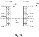
ビデオフレームfが処理された後、そのフレームのウェーブレット係数値はシーケンスの次のフレームを処理する際に使用するためにメモリの記憶場所915に格納される。1つの実現形態では、ウェーブレット係数値の全てが格納される。しかし、ビデオフレームのウェーブレット係数値のサブセットのみが格納されるのが好ましい。例えば、フリッカ減少方式711は2ビットしか必要としないため、章5.0で更に説明するように、切り捨てられた係数のうちの2つの最下位ビットのみが格納されれば良い。
After video frame f has been processed, the wavelet coefficient values for that frame are stored in
ビデオフレームfを処理した後、フレームfの各コードブロックの切捨てポイントはメモリ906の記憶場所911に格納される。切捨てポイント情報は、次のフレームを順次処理する際に符号化を終了させるべきか否かを考慮するときに使用される。1つの実現形態では、記憶場所911は各コードブロックの切捨てビットプレーンLnを格納する。この実現形態は、例えば、ビデオフレームの符号化中にPCRD−optルーチンが使用される場合に使用できるであろう。
After processing video frame f, the truncation point of each code block of frame f is stored in
記憶場所911に各コードブロックnの切捨てビットプレーンLnを格納するもう1つの方法は、コードブロックごとに最終ビットストリームに含まれるコーディングパスの数を格納する。コーディングパスは0でないビットプレーンのみを符号化するために採用される。コーディングパスを要求する0でないビットプレーンに到達する前に、1つ以上の0であるビットプレーンに遭遇する可能性はある。コードブロックnの0であるビットプレーンの数をAnとする。
Another way of storing the truncated bit plane L n of each code block n in
第1の構成において、記憶場所911に格納される値は次の式により表される。
式中、Inはコードブロックnのビットストリームに含まれるコーディングパスの数である。尚、各ビットプレーンと関連するコーディングパスは通常は3つ存在していることに注意する。コードブロックの0であるビットプレーンの数はフレームごとに異なるため、各コードブロックにおける0であるビットプレーンを補償することにより、次のフレームにおける切捨てポイントの等価の位置を厳密に推定することができる。
In the first configuration, the value stored in the
Wherein the I n is the number of coding passes included in the bit stream of code block n. Note that there are usually three coding paths associated with each bit plane. Since the number of bit planes that are 0 in the code block differs from frame to frame, the equivalent position of the truncation point in the next frame can be accurately estimated by compensating for the bit plane that is 0 in each code block. .
1つのビデオフレームにおけるコードブロックごとの絶対切捨てビットプレーンは、切捨てポイントが判定された後に格納される。切捨てポイントの記憶場所911への格納は、図7のステップ506の間に起こるのが好ましい。
The absolute truncation bit plane for each code block in one video frame is stored after the truncation point is determined. Storage of the truncation point in
記憶場所913は、フレームの各成分について実現された速度を格納する。図9は、1つの実現形態においては、画像のY成分、Cb成分及びCr成分である3つの成分を示す。尚、ビデオフレームについて実現される総合速度は成分ごとの実現速度の和であることに注意する。すなわち、
式中、Mは成分の数である。
In the formula, M is the number of components.
フレームfのカットオフ閾値λfは記憶場所912に格納される。目標速度Rtargetは記憶場所914に格納される。
Cutoff threshold lambda f of the frame f is stored in
記憶場所916はコードブロックnごとの速度−ひずみ傾きを格納するために使用される。
3.3 カットオフ閾値の推定
画像を符号化するときに適切な速度制御を実行するためには、適切なカットオフ傾き閾値を選択することが重要である。ビデオシーケンスで現在の画像に関してλfを推定することは、先行するビデオフレームのカットオフ速度‐ひずみ傾き閾値λf-1及び先行するフレームの実現速度Rf-1 achievedを使用することを含む。言い換えれば、フレームfのλfは、λf-1、Rf-1 achieved及び目標ビットレートRtargetの関数である。
3.3 Estimation of cut-off threshold In order to perform proper speed control when encoding an image, it is important to select an appropriate cut-off slope threshold. Estimating λ f for the current image in the video sequence includes using the preceding video frame cut-off rate-distortion slope threshold λ f−1 and the preceding frame achieved rate R f−1 achieved . In other words, λ f of frame f is a function of λ f−1 , R f−1 achieved and target bit rate R target .
第1の構成においては、λ1、すなわち、ビデオシーケンスにおける第1のフレームの傾き閾値はPCRD−optアルゴリズムにより選択されるのが好ましいが、他の選択方法が使用されても良い。 In the first configuration, λ 1 , ie, the slope threshold of the first frame in the video sequence, is preferably selected by the PCRD-opt algorithm, but other selection methods may be used.
後続するフレームに関しては、f≠1の場合のλfは次のように推定される。
及び
![]()
従って、現在のフレームに関して、プロセッサ2705は、メモリ906に格納されている先行するフレームからの値を使用して傾きカットオフ閾値を計算する。
For subsequent frames, λ f for f ≠ 1 is estimated as follows.
as well as
![]()
Thus, for the current frame,
第1の構成においては、λfは符号化ステップに先立って現在のフレームに関して計算される。 In the first configuration, λ f is calculated for the current frame prior to the encoding step.
3.4 静的コードブロック切捨て安定化
第1の構成は静的ブロック切捨て安定化方式712を含む。図10は、ビデオシーケンスの各フレームをMJ2Kフォーマットに圧縮する方法を示す。図10は図7のステップの多くを含むが、静的ブロック切捨て安定化712を伴う符号化ステップ705に関して更に詳細に示す。特に、ステップ1003から1006は図7のステップ705及び712に対応している。
3.4 Static Code Block Truncation Stabilization The first configuration includes a static block
方法はステップ700で始まり、次に、ループ701に入る、ループが繰り返されるたびに、ビデオシーケンスの現在のフレームが圧縮される。全てのフレームが圧縮されると、ループ701は終了し、方法はステップ710で終了する。
The method begins at
ループ701の中では、プロセッサ2705はステップ1002で現在のビデオフレームfに対してウェーブレット変換ステップを実行するが、それらのステップは前処理ステップ501、ウェーブレット変換ステップ502、量子化ステップ503及び、好ましくはフリッカ減少ステップ711を含む。
Within
次に、プロセッサ2705で実行されるプログラムは、fの各コードブロックnfを符号化するためのループ1003に入る。コードブロックごとに、ステップ1004でモーション検出パラメータが計算される。このステップについては、図11を参照して以下に更に詳細に説明する。ステップ1004で、プロセッサ2705は現在のコードブロックnfを先行するフレーム(f−1)の対応するコードブロックnf-1と比較する。コードブロックnfとコードブロックnf-1との間でモーションが検出されなければ、コードブロックnfは「静的」であるとフラグ付けされる。そうでない場合には、コードブロックnfは「非静的」コードブロックであるとフラグ付けされる。
Next, the program executed by the
モーション検出パラメータが計算されると、ステップ1005でフレームfが符号化される。この符号化は符号化手続きを終了させる方法を使用する。ステップ1005では、現在のコードブロックが静的であるか又は非静的であるかに応じて、様々に異なる終了戦略が適用される。ステップ1005については、以下に図12を参照して更に詳細に説明する。
Once the motion detection parameters are calculated, frame f is encoded at
次に、ステップ1006で、プロセッサは、フレームfに関して処理すべきコードブロックがまだ存在しているか否かを判定するために試験を実行する。試験1006が肯定の応答を戻した場合、方法はステップ1004に戻って、フレームfの次のコードブロックを処理する。しかし、試験1006が否定の応答を戻した場合(すなわち、現在のフレームにそれ以上のコードブロックが存在しない場合)には、プロセス流れはステップ1007へ進む。
Next, in
ステップ1007で、プロセッサ2705は各コードブロックnf∈[n=1,...,N]の切捨てポイントを判定し、格納する。尚、Nはfにおけるコードブロックの総数である。各コードブロックnfの切捨てポイントは、λin≦λfに対応する最大のポイントinを選択することにより判定される(すなわち、図7のステップ706)。別の実現形態は、JPEG2000規格により推奨されているPCRD−optルーチンを使用することを含む(すなわち、図7のステップ505)。他の速度制御戦略が使用されても良い。ステップ1007で判定された切捨てポイントの集合は、次のフレームf+1を処理するときに使用するためにメモリ911に格納される。
In
次に、符号化値はビットストリームとして編成される(ステップ506)。 Next, the encoded values are organized as a bit stream (step 506).
ステップ709で、現在のフレームfがビデオシーケンスの最終フレームであるか否かを判定するための試験が実行される。試験709が否定の応答を戻した場合、処理はステップ1002に戻り、シーケンス中の次のフレームを処理する。試験709が肯定の応答を戻した場合(すなわち、それ以上のフレームが存在しない場合)には、ループ701から出て、方法はステップ710で終了する。
At
3.4.1 コードブロック間のモーションの計算
モーション検出パラメータを計算するステップ1004について、図11を参照して更に詳細に説明する。パラメータ計算はステップ1100で始まり、ステップ1101へ進み、モーション検出を実行するために使用される全ての必要なパラメータが0に初期設定される。
3.4.1 Calculation of motion between code blocks Step 1004 of calculating motion detection parameters will be described in more detail with reference to FIG. Parameter calculation begins at
初期設定されるパラメータは、コードブロックが静的ブロックであるか又は非静的ブロックであるかを示すために使用されるStaticBlockフラグと、Md(モーション検出パラメータ)である。Mdの計算で使用される3つのパラメータ、すなわち、CorrelCurrPrev、CorrelCurr及びCorrelPrevも0に初期設定される。 The parameters to be initialized are a StaticBlock flag used to indicate whether the code block is a static block or a non-static block, and Md (motion detection parameter). Three parameters used in the calculation of Md, namely CorrelCurrPrev, CorrelCurr and CorrelPrev are also initialized to zero.
第1の構成では、Mdは次のように計算されるのが好ましい相関係数である。
式中、x1,x2,...,xL及びy1,y2,...,yLは、共にエントリ数Lを有する2つのベクトルX及びYに対するエントリである。Xはコードブロックnfのベクトル化表現であり、Yはコードブロックnf-1に対応するベクトル化表現である。Lはコードブロックnfのサイズである。例えば、コードブロックnfが高さ×幅の大きさである場合、L=高さ×幅である。
In the first configuration, Md is a preferred correlation coefficient that is calculated as follows.
Where x 1 , x 2 ,..., X L and y 1 , y 2 ,. . . , Y L are entries for two vectors X and Y, both having the number of entries L. X is a vector representation of the code block n f, Y is a vector representation corresponding to the code blocks n f-1. L is the size of the code block n f. For example, when the code block n f has a size of height × width, L = height × width.
変数の初期設定の後、ループ1102に入り、コードブロックnfの各ウェーブレット係数を順次処理する。現在考慮されている係数はCnである。係数ごとに、ステップ1103で、現在のフレームf=1であるか否かを判定するために試験が実行される。f=1であれば(ステップ1103のYesオプション)、先行するフレームとの比較を実行することができず、ウェーブレット係数に対する修正なしにコードブロックnfは符号化される。ステップ1102のYesオプションの場合、プロセス流れは直接にステップ1106へ進む。ステップ1103が否定の応答を戻した場合(すなわち、現在のフレームが第1のフレームではない場合)には、コードブロックnfのあらゆるウェーブレット係数に対して、ステップ1104でメモリからコードブロックnf-1の対応するウェーブレット係数が検索される。先行するフレームの係数は記憶場所915に格納される。
After initial setting of the variable, the
ステップ1105で、変数CorrelCurrPrev、CorrelCurr及びCorrelPrevは次のように更新される。
現在のコードブロックの全ての係数Cnが処理され終わると、以下の合計が得られることが理解されるであろう。
In
It will be appreciated that once all coefficients C n of the current code block have been processed, the following sum is obtained:
1. Xがコードブロックnfである場合、
ステップ1108では、式(15)を使用してMdが計算される。ステップ1109で、Mdが閾値Tsより大きいか否かを判定するために試験が実行される。Mdが閾値より大きい場合(ステップ1109のYesオプション)、ステップ1110で、StaticBlockフラグは、現在のコードブロックが先行するコードブロックと極めて大きく相関していることを示す1に設定される。Mdが閾値より小さい場合には(ステップ1109のNoオプション)、StaticBlockは0で変わらないままである。プロセス流れはステップ1005で戻る。
In
第1の構成では、閾値Tsは0.9に設定される。他の値も可能である。1つの実現形態においては、異なるDWTレベルに対して異なるTsの値が使用される。別の実現形態では、画像の異なる成分に対して異なるTsの値が使用される。Tsの値が低くなるほど、安定化プロセスの効率は高くなる。しかし、画質との間に妥協点がある。 In the first configuration, the threshold Ts is set to 0.9. Other values are possible. In one implementation, different Ts values are used for different DWT levels. In another implementation, different Ts values are used for different components of the image. The lower the value of Ts, the higher the efficiency of the stabilization process. However, there is a compromise between image quality.
フレーム間で係数ごとに2ビットしか格納されない場合、相関係数Mdはそれら2つの利用可能なビットのみを使用して計算される。このようにして計算される相関成分でも、フレーム間のモーションの変化を示す。 If only 2 bits per coefficient are stored between frames, the correlation coefficient Md is calculated using only those 2 available bits. The correlation component calculated in this way also shows a change in motion between frames.
3.4.2 ブロックを符号化する際のモーション検出パラメータの使用
図12は、ステップ1004で計算されたモーション検出パラメータが現在のコードブロックnfの符号化を終了させるべきか否かを判定するときにどのように使用されるかを示す。図12のステップはステップ1005に対応している。
3.4.2 Use of motion detection parameters when encoding a block FIG. 12 determines whether the motion detection parameters calculated in
ステップ1201で、現在の符号化パスTfは0に設定される。次に、ステップ1203で、先行するビデオフレームの対応するコードブロックnf-1の切捨てポイントT(f−1)がメモリ911から検索される。
In
次に、ステップ1205で、通常のJPEG2000符号化方法を使用してコードブロックnfが符号化される。次に、ステップ1207で、現在のブロックのStaticBlockフラグが1に設定されているか否かを判定するために試験が実行される。現在のブロックが静的ブロックであれば(ステップ1207のYesオプション)、プロセス流れはステップ1209へ進む。しかし、現在のブロックが静的ブロックではない場合には(ステップ1207のNoオプション)、プロセス流れはステップ1211へ進む。
Next, in
ステップ1209で、プロセッサ2705は現在のコーディングパスT(f)の値をT(f−1)の値と比較する。Tf=T(f−1)であり且つ現在のコードブロックが静的コードブロックである場合(ステップ1209のYesオプション)、現在のコードブロックの符号化はステップ1212で終了される。
At
しかし、T(f)がまだT(f−1)と等しくない場合には(ステップ1209のNoオプション)、プロセス流れはステップ1211へ進む。 However, if T (f) is not yet equal to T (f-1) (No option at step 1209), the process flow proceeds to step 1211.
現在のブロックが静的ブロックではない場合又はTfがまだT(f−1)と等しくない場合には、ステップ1211が実行される。ステップ1211では、現在のブロックについてまだコーディングパスが存在するか否かを判定するために試験が実行される。まだコーディングパスがあれば(ステップ1211のYesオプション)、プロセス流れはステップ1205に戻る。しかし、現在のブロックについてそれ以上コーディングパスが存在しない場合には(ステップ1211のNoオプション)、現在のブロックの符号化はステップ1212で終了する。
If the current block is not a static block or if T f is not yet equal to T (f−1),
ステップ1212で現在のブロックの符号化が完了すると、処理はステップ1006で再開する。
When encoding of the current block is complete at
3.5 フレーム従属成分重み付け
第1の構成は、各ビデオフレームの画像成分に適応重み付けする方法を提供する。このフレーム従属成分重み付け方法713は、YCbCr色空間において輝度成分と色信号成分に対して異なるカットオフ速度−ひずみ閾値λfを使用する。以下の説明中、成分0は輝度成分Yを表し、成分1及び2は、それぞれ、色信号成分Cb及びCrを表す。輝度成分は色信号成分より大きい影響を認知画質に対して及ぼし、従って、重み付け方法713は色信号成分を犠牲にしても輝度成分の符号化を優先する。
3.5 Frame Dependent Component Weighting The first configuration provides a method for adaptively weighting the image components of each video frame. This frame dependent
異なる成分に対する重み付けλfは、視覚重み付けを適用する方法に対する改善である。図13及び図14をそれぞれ参照して、2つの二者択一的な重み付け方法を説明する。これら2つの方法のいずれにおいても、現在のフレームの圧縮度は先行するフレームに関して判定される。第1のバージョンでは、圧縮度は色信号成分に基づいて推定される。フレームがより多く圧縮可能である(すなわち、色信号成分を符号化するために要求されるビットの数がより少ない)と判定された場合、輝度成分に割り当てられるビットバジェットは増加する。 The weighting λ f for the different components is an improvement over the method of applying visual weighting. With reference to FIGS. 13 and 14, respectively, two alternative weighting methods will be described. In either of these two methods, the degree of compression of the current frame is determined with respect to the preceding frame. In the first version, the degree of compression is estimated based on the color signal component. If it is determined that the frame is more compressible (ie, fewer bits are required to encode the color signal component), the bit budget allocated to the luminance component is increased.
重み付け方法713の第2のバージョンでは、輝度成分の符号化はある1つのひずみレベルに維持され、色信号成分の符号化は、輝度成分の過剰符号化がある場合にそれを補償するために重み付けされる。
In the second version of the
更に、方法713の第1のバージョンは、ビデオフレームの圧縮データを色信号成分に限定されるようにトリミングさせることができる。従って、フレームの輝度成分の圧縮が余りにも寛容であった場合には、そのフレームの色信号成分からより多くのデータをトリミングして、ビットを節約することになる。
Further, the first version of the
3.5.1 輝度カットオフ閾値の重み付け
図13は、輝度カットオフ閾値が潜在的に調整される成分重み付け方式713を示す。図7を参照すると、図13は、成分重み付け方式713を利用する符号化ステップ705に関して更に詳細に示している。明瞭にするため、図13は図7のステップの一部を再現している。例えば、図13のステップ1300、1301、1312及び1313は図7のステップ700、701、709及び710に対応している。成分重み付け方式がビデオシーケンスの各フレームに順次適用されることを強調するために、それらのステップは図13でも保たれている。
3.5.1 Luminance cutoff threshold weighting FIG. 13 shows a
フレーム従属成分重み付けの方法713はステップ1300で始まり、次に、プロセッサ2705がビデオシーケンスの各フレームを順次処理するループ1301に入る。ループ1301では、プロセッサ2705は第1のパスでビデオシーケンスの第1のフレームを処理し、後続するパスの間にビデオの後続するフレームを処理する。ビデオの全てのフレームが処理され終わった後、ステップ1312でループ1301を出て、方法はステップ1313で終了する。
The frame dependent
ループ1301の中のステップ1302で、プロセッサ2705は、まず、章3.3で先に説明したように現在のフレームfのカットオフ閾値λfを判定する。また、現在のフレームは、現在のフレームを符号化するためのビットバジェットを判定する目標ビットレートを有する。
At
次に、(図7のステップ501〜503で示されるように)前処理、成分変換及び量子化などの通常のJ2K符号化ステップがプロセッサ2705により実行される。次に、ループ1303に入り、ビデオフレームの各成分を順次処理する。ループ1303では、プロセッサ2705は、まず、色信号成分を処理し、その後の最終パスで輝度成分を処理する。すなわち、ループ1303は成分を1、2、続いて0の順に処理する。
Next, normal J2K encoding steps such as preprocessing, component transformation and quantization are performed by the processor 2705 (as indicated by steps 501-503 in FIG. 7). Next, a
ステップ1304では、現在の成分が2つの色信号成分のうちの一方であるか否かを判定するために、プロセッサ2705により試験が実行される。試験1304が肯定の応答を戻した場合、ステップ1302で判定されたλfを使用して通常のJ2K符号化プロセスに従って現在の成分を符号化するために、ステップ1305が実行される。現在の成分が符号化された後、ステップ1306で、プロセッサ2705は現在の成分が成分2であるか否かを判定するために試験を実行する。現在の成分が1であれば(ステップ1306のNoオプション)、処理はステップ1308へ続き、現在の成分と関連する値がメモリ906にセーブされる。特に、現在の成分の実現速度が記憶場所913にセーブされる。
In
次のステップ1309で、プロセッサ2705は現在の成分が最後の成分であるか否かを判定するために試験を実行する。試験1309が否定の応答を戻した場合、プロセス流れはステップ1304に戻り、次の成分を処理する。
At the
現在の成分が2である場合には(ステップ1306のYesオプション)、メモリ906から先行するフレームの統計値を検索するためにステップ1307が実行される。検索される統計値は先行するフレームf−1の実現成分速度Rachievedを含む。ステップ1307では、プロセッサは輝度成分を符号化するときに使用されるべきλfの重み付けを更に計算する。重み付けは、現在のビデオフレームの総合圧縮度を推定するために、現在のフレームfと先行するビデオフレームf−1の双方の色信号成分の実現速度を使用する。例えば、現在の成分の実現速度が先行するビデオフレームの実現速度より速い場合、現在のビデオフレームは先行するビデオフレームと比較して圧縮度が低いと思われる。第1の構成はこの情報を使用して、輝度成分をより有効に符号化する。
If the current component is 2 (Yes option of step 1306),
ステップ1307で現在のフレームがより圧縮度が高いと判定された場合、輝度成分の実現速度を増加させるようにλfが重み付けされるのが好ましい。現在のフレームがより圧縮度が高いとき、それは色信号成分を符号化するのに使用されるビットの数がより少なく、従って、フレームの目標ビットレート内にとどまりつつ、輝度成分を符号化するためにより多くのビットを利用できることを意味している。
If it is determined in
ステップ1307で、プロセッサ2705は次の式に従ってλfを調整する。
式中、Rfm achievedは現在のフレームfにおける成分mの実現速度であり、R(f-1)m achievedは先行するフレームf−1における成分mの実現速度である。
At
In the equation, R fm achieved is the realized speed of the component m in the current frame f, and R (f-1) m achieved is the realized speed of the component m in the preceding frame f-1.
現在のフレームが先行するフレームより低い圧縮度である場合、式(16)の重み付け係数は1に限定される。重み付け係数を1に限定する理由は、輝度が色信号成分より大きな影響を認知画質に対して及ぼすからである。従って、圧縮度の低いフレームの場合、輝度成分の符号化は妥協されない。そこで、色信号成分をトリミングすることが必要になるであろう(以下のステップ1310を参照)。
If the current frame is less compressed than the preceding frame, the weighting factor in equation (16) is limited to 1. The reason for limiting the weighting coefficient to 1 is that the luminance has a greater influence on the perceived image quality than the color signal component. Therefore, in the case of a frame with a low compression degree, the coding of the luminance component is not compromised. Therefore, it will be necessary to trim the color signal component (see
ステップ1307が完了した後、プロセス流れはステップ1308へ進み、現在の係数の実現速度がメモリ906に格納される。
After
現在の成分が輝度成分であれば(ステップ1304のNoオプション)、ステップ1314で、ステップ1307で判定された調整済みλfを使用して成分の符号化が実行される。尚、ステップ1307でλfが減少された場合、一般に、そうでない場合よりも多くのコーディングパスが輝度成分の符号化に使用される。ステップ1314の後、プロセス流れはステップ1308へ進み、実現速度をメモリ906にセーブする。
If the current component is a luminance component (No option at step 1304), then at
現在のビデオフレームfの全ての成分が処理された後(ステップ1309のYesオプション)、ステップ1310に入り、データがトリミングを要求するか否か、すなわち、目標ビットレートを超過したか否かを判定する。トリミングが要求されていれば(ステップ1310のYesオプション)、成分1及び2の圧縮データをトリミングするためにステップ1311が実行される。圧縮データのトリミングは、λin≦Z(所定の閾値)である成分1及び2のコードブロックnfのコーディングパスinの圧縮データを放棄することから成る。閾値Zは次のように判定されるのが好ましい。
トリミングステップ1310及び1311は図7の符号化後トリミングステップ706に対応している。
After all components of the current video frame f have been processed (Yes option of step 1309),
Trimming
ステップ1311が完了した後、ステップ1312は、現在のフレームが最終フレームであるか否かを検査する。フレームが残っていれば(ステップ1312のNoオプション)、プロセス流れはステップ1302に戻り、次のフレームを処理する。それ以上フレームが存在しない場合には、プロセスはステップ1313で終了する。
After
トリミングプロセスが要求されない場合(ステップ1310のNoオプション)、ステップ1311を飛び越し、処理はステップ1312へ続く。
If the trimming process is not required (No option at step 1310),
3.5.2 色信号カットオフ閾値の重み付け
図14は、フレーム従属成分重み付け方式713の別の実現形態を示す。この場合、輝度成分のカットオフは調整されず、推定された圧縮度に従って色信号成分の重み付けが重み付けされる。
3.5.2 Color Signal Cutoff Threshold Weighting FIG. 14 shows another implementation of the frame dependent
方法は1400で始まり、ビデオシーケンスの各フレームを順次処理するループ1401に入る。全てのビデオフレームが処理された後、ステップ1410でループ1401から出て、方法は1411で終了する。
The method begins at 1400 and enters a
ループ1401の中で、ステップ1402において、プロセッサ2705は現在のビデオフレームfのカットオフ閾値λfを判定する。ステップ1402はステップ1302と同じであり、章3.3で説明した手続きを使用する。次に、現在のフレームに対して前処理及び成分変換などの通常のJ2K符号化処理ステップ(図7のステップ501〜503)が実行される。
Within the
次に、ステップ1403で、現在のビデオフレームの各成分を順次処理するためのループに入る。ループ1403において、プロセッサ2705は、まず、輝度成分を処理し、次に後続するパスで色信号成分の各々を順次処理する。従って、ループ1403は成分を0、1、2の順に処理することになる。
Next, in
ステップ1404では、現在の成分が輝度成分であるか否かを判定するために試験が実行される。試験1404が肯定の応答を戻した場合、プロセス流れはステップ1406へ進み、ステップ1402で判定されたλfを使用して、通常のJ2K符号化プロセスに従って成分を符号化する。成分が符号化された後、ステップ1407はメモリ906から先行するビデオフレームf−1の関連統計値を検索する。特に、先行するフレームで実現された速度がメモリ913から検索される。
In
ステップ1407は、色信号成分を符号化するときに使用されるべきλfの重み付けを更に判定する。現在のフレームf(ステップ1406で判定される)と先行するフレームf−1の双方の輝度成分の実現速度に基づいて、現在のビデオフレームの総合圧縮度を推定することができる。従って、fの輝度成分の実現速度がf−1の輝度成分より高ければ、ビデオfの圧縮度はビデオフレームf−1より低いと思われる。これに従って、fの色信号成分の実現速度を低減するために、カットオフ閾値λfが重み付けされる。
閾値λfは次の式に従って重み付けされるのが好ましい。
式中、m=0、すなわち、輝度成分である。
The threshold λ f is preferably weighted according to the following formula:
In the formula, m = 0, that is, a luminance component.
現在の成分に対して符号化が完了した後、次のフレームを処理するときに使用するのに備えて成分の実現速度をメモリ916にセーブするためにステップ1408が実行される。
After encoding is completed for the current component,
現在の成分が色信号成分の一方である場合には(ステップ1404のNoオプション)、ステップ1405で、先にステップ1407で判定された重み付きλfを使用して現在の色信号成分が符号化される。プロセッサ2705で実行されるプログラムは次にステップ1408へ進み、現在の成分の実現速度をメモリ913にセーブする。
If the current component is one of the color signal components (No option in step 1404), then in
次に、ステップ1409は現在の成分が最後の成分であるか否かを検査する。フレームの他の成分が存在する場合、プロセス流れはステップ1404に戻り、次の成分を処理する。全ての成分が処理され終わっている場合には(ステップ1409のYesオプション)、ステップ1410は現在のフレームが最終フレームであるか否かを検査する。全てのフレームが処理され終わっている場合(ステップ1410のYesオプション)、ループ1401から出て、方法は1411で終了する。そうでない場合には(ステップ1410のNoオプション)、プロセス流れはステップ1402に戻り、次のフレームを順次処理する。
Next,
3.6 符号化方式
第1の構成は、現在のビデオフレームfのコードブロックnfごとの過剰符号化の量を減少させる符号化方式714を使用する。符号化方式714は、フレームf中のコードブロックの符号化を終了させるべき時点を決定するために、ビデオシーケンスの先行するフレームにおけるコードブロックの切捨てポイントを使用する。
3.6 Coding scheme The first configuration uses a
図15は、図7の符号化プロセスで使用された符号化方式714を示す。明瞭にするため、図15は図7のステップの全てではないが、その一部を再現している。プロセスはステップ700で始まり、ビデオシーケンスの各フレームfを順次処理するためのループ701に入る。ループ701は第1回目の繰り返しでビデオシーケンスの第1のフレームを処理し、後続する繰り返しの中で、ループ701はビデオの対応する後続フレームを処理する。ビデオの全てのフレームが処理された後、ステップ709でループ701を出て、方法はステップ710で終了する。
FIG. 15 shows the
ループ701の中で、符号化方法は図15に示されていないいくつかのステップを実行する。ビデオフレームごとに、方法はカットオフ閾値λfを推定し(図13のステップ1302)、次に、プロセッサ2705は前処理、離散的ウェーブレット変換(DWT)及び量子化から成る標準J2K符号化ステップ(図7のステップ501〜503)を実行する。次に、ループ701は、ビデオフレームfの各コードブロックnfを順次処理するための別のループ1502に入る。全てのコードブロックnfが処理され終わった後、ステップ1509でループ1502を出て、処理は、コードブロックnfの切捨てポイントを格納するステップ1510へ続く。
Within the
ループ1502の中で、ステップ1503において、プロセッサ2705は先行するフレームf−1の対応するコードブロックnf-1の切捨てポイントをメモリ906から検索する。尚、第1のフレームを符号化するときに使用すべき先行するフレームからの情報は存在しないので、第1のフレームは特殊ケースとして扱われることに注意する。従って、第1のフレームの場合、ステップ1503及び1504は省略され、第1のフレームの符号化はステップ1505で始まる。
Within the
ステップ1504では、現在のコードブロックnfの符号化を進めるべきか否かを判定するために試験が実行される。ステップ1504は、現在のコードブロックが静的ブロックであるか否か及びコードブロックnf-1が符号化されたか否か(すなわち、ビットストリームの中で有意ビットプレーンが符号化されたか否か)を検査する。コードブロックnfが静的ブロックであるか否かを判定するための手続きについては、先に図11を参照して説明した。コードブロックnfが静的コードブロックであると判定され、コードブロックnf-1は符号化されていなかった場合(ステップ1504のYesオプション)、処理はステップ1509へ進み、コードブロックnfの符号化は実行されない。しかし、試験1504が否定の応答を戻した場合には(ステップ1504のNoオプション)、プロセス流れはステップ1505へ進む。
In
ステップ1505では、コードブロックnfの各コーディングパスを符号化するためのループに入る。特定の1つのコードブロックについて符号化すべきコーディングパスの最大数は、符号化に先立って判定される(図示せず)。パスの最大数は標準JPEG2000方法を使用して判定される。尚、J2Kでは、ビットプレーンごとに名目上は3つのコーディングパスが存在することに注意する。
In
ループ1505の中で、ステップ1506においては、プロセッサ2705はコードブロックnfの量子化ウェーブレット係数を符号化する。最初にループ1505に入るとき、ステップ1506はクリーンアップパスを実行する。それに続く繰り返しでは、ステップ1506は、有意性伝播パスから再開する前に、有意性伝播パス、マグニチュード精密化パス又はクリーンアップパスをこの順序で実行する。1つのコーディングパスを符号化した後、符号化ステップ1506は現在のコーディングパスと関連するひずみ値及び速度を判定する。ひずみ及び速度は、現在のコーディングパスの後に符号化を終了させるべきか否かを判定するために使用される。終了試験はコーディングパス1506が完了するたびにステップ1507で実行されるが、この試験については以下に図16を参照して更に詳細に説明する。
Within
終了試験1507が否定であり且つ処理すべきそれ以上のコーディングパスが存在しない場合、処理はステップ1506に戻り、次のコーディングパスを処理する。しかし、終了試験1507が肯定であれば、現在のコーディングパスは最終コーディングパスと判定され、プロセス流れはステップ1508へ進み、コードブロックnfの符号化を終了する。
If
ステップ1507は、コードブロックnfの終了ポイントを確定する。次に、ステップ1508で、コードブロックnfに対してトリミングが適用される。トリミングは、コードブロックnfの切捨てポイントを判定することと、速度−ひずみ傾きλin≦λfを有するコーディングパスinの圧縮データを放棄することから成る。ステップ1508で実行されるトリミングは、ステップ706の符号化後トリミングに対応している。
トリミングが完了した後、ステップ1509で、プロセッサ2705は現在のコードブロックが最後のコードブロックであるか否かを試験する。処理すべきコードブロックがそれ以上存在しない場合(ステップ1509のNoオプション)、処理はステップ1503に戻る。しかし、全てのコードブロックが処理され終わっている場合には(ステップ1509のYesオプション)、ループ1502から出る。
After trimming is complete, at
全てのコードブロックが処理された後、図15には示されていないが、いくつかの標準J2K符号化ステップが実行される。符号化ステップはビットストリーム編成(図7のステップ506)を含む。
After all code blocks have been processed, some standard J2K encoding steps are performed, not shown in FIG. The encoding step includes bitstream organization (
次に、ステップ1510で、次のビデオフレーム(f+1)を処理するときに使用するために、全てのコードブロックの切捨てポイントがメモリ911に格納される。次に、ステップ709は現在のフレームが最終フレームであるか否かを試験する。これが当てはまらない場合(ステップ709のNoオプション)、プロセス流れはステップ1502に戻り、シーケンス中の次のフレームを符号化する。それ以上のフレームが存在しない場合には(ステップ709のYesオプション)、方法はステップ710で終了する。
Next, at
3.6.1 終了基準
次に、図16を参照して、コードブロックnfの終了ポイントを判定する手続きを更に詳細に説明する。図16において、ステップ1603〜1608は図15のステップ1507に対応している。第1の構成では、コーディングパスの後にコードブロックnfを終了させるための決定はコードブロックnf-1の切捨てポイントを利用する。
3.6.1 Termination Criteria Next, a procedure for determining the termination point of the code block n f will be described in more detail with reference to FIG. In FIG. 16,
図16を参照すると、図15を参照して先に説明したようにコードブロックnfの各コーディングパスを処理するためにループ1505に入る。要求される全てのコーディングパスを符号化した後、ループ1505を出て、プロセス流れはステップ1508へ進み、符号化プロセスを終了する。尚、コードブロックnfの符号化プロセスの終了は、通常、コードブロックnfの最終コーディングパスを符号化する前に起こることに注意する。
Referring to FIG. 16, a
ステップ1603は、現在のコードブロックnfが静的コードブロックであるか否か及び現在の符号化プロセスが対応するコードブロックnf-1と同じ切捨てポイント(ビットプレーン)に到達したか否かを試験する。これら2つの条件に適合していると(ステップ1603のYesオプション)、コードブロックnfの符号化は終了し、プロセス流れはステップ1508へ進み、符号化を終了する。しかし、現在のコードブロックが静的ブロックではない場合又は対応する先行するコードブロックの切捨てポイントにまだ到達していない場合には(ステップ1603のNoオプション)、プロセス流れはステップ1604へ進み、更に終了試験が実行される。コードブロックが静的ブロックであるか否かを判定する手続きについては、先に図11に関して説明した。
コードブロックnfに対して、符号化ステップ1506は現在のコーディングパスinの速度−ひずみ傾きλinを計算する。ステップ1604は、速度−ひずみ傾きλinが現在のフレームのカットオフ閾値λfより大きいか否かを試験する。カットオフ閾値の計算については先に章3.3で説明した。現在のコーディングパスの速度‐ひずみ傾きがカットオフ閾値より大きい場合(ステップ1604のNoオプション)、処理はステップ1506に戻り、次のコーディングパスを符号化する(すなわち、in=in+1)。しかし、現在のコーディングパスの速度‐ひずみ傾きがカットオフ閾値より小さい場合には(ステップ1604のYesオプション)、プロセス流れはステップ1605へ進み、更に試験が実行される。
For code blocks n f, the
ステップ1605はループ1505においてコードブロックnfに関してそれまでに処理されたすべてのコーディングパスを検査し、0でないλinを有するクリーンアップコーディングパスが存在するか否か、すなわち、現在のコードブロックについて少なくとも1つのクリーンアップパスで有意ビットが符号化されたか否かを判定する。試験1605が肯定の応答を戻した場合(すなわち、クリーンアップパスで以前に有意ビットが符号化されていた場合)、プロセス流れはステップ1606へ進み、更に試験が実行される。試験1605が否定である場合(すなわち、0でないλinを有するクリーンアップコーディングパスが存在する場合)には、プロセス流れはステップ1506に戻り、次のコーディングパスを符号化する。
ステップ1606では、プロセッサ2705は、コードブロックnf-1で3つ以上の有意ビットプレーンが符号化されたか否かを試験する。試験1606が否定の応答を戻した場合、処理はステップ1608へ続く。試験1606が肯定の応答を戻した場合(すなわち、コードブロックnf-1で3つ以上の有意ビットプレーンが符号化されていた場合)には、ステップ1607で別の試験が実行される。ステップ1607で、コードブロックnfについてそれまでに3つ以上の有意ビットプレーンが符号化されていた場合(ステップ1607のYesオプション)、処理はステップ1608へ続く。しかし、試験1607が否定の応答を戻した場合には、処理はステップ1506に戻り、次のコーディングパスを処理する。
At
ステップ1608では、ステップ1506でコーディングパスinにより生成された圧縮データがAバイトの長さを超えるか否かを判定するために、更に試験が実行される。第1の構成では、A=3バイトであるのが好ましい。試験1608が否定の応答を戻した場合、処理はステップ1506に戻り、別のコーディングパスを処理する。しかし、試験1608が肯定の応答を戻した場合(すなわち、生成されたコード語がAバイトを超える場合)には、ループ1505を出て、プロセス流れはステップ1508で再開する。ループ1505を出ることにより、現在のコーディングパスはコードブロックの終了ポイントとして確定される。
In
第1の構成の変形においては、例えば、バイトがクリーンアップパスなどの特定の種類のコーディングパスによりコード語に寄与されたか否かを検査するなど、追加の終了条件も可能である。更に、異なる値のAを使用しても良いであろう。 In a variation of the first configuration, additional termination conditions are possible, for example, checking whether a byte was contributed to a code word by a particular type of coding pass, such as a cleanup pass. In addition, different values of A could be used.
3.7 符号化後トリミング
先に述べた通り、第1の構成は、以下に図17を参照して説明する符号化後トリミングの方法を使用する。図17のステップは図7のステップ706に対応しており、図15のステップ1508のトリミングにおいても使用される。トリミング方法は、1つのコードブロックの符号化が終了した後に一度適用される。コードブロックを符号化することにより、第1のコーディングパスから符号化が終了した最終コーディングパスまでの一連のコーディングパスが得られる。各コーディングパスと関連して、速度−ひずみ傾きが存在する。
3.7 Trimming After Encoding As described above, the first configuration uses the post-coding trimming method described below with reference to FIG. The step in FIG. 17 corresponds to step 706 in FIG. 7 and is also used in the trimming in
トリミング方法はステップ1700で始まり、コードブロックnfの第1のコーディングパスから始めて、コードブロックnfのコーディングパスを巡って繰り返すためのループ1701に入る。
Trimming method begins at
ループ1701の中で、ステップ1702では、プロセッサ2705は、現在のコーディングパスinの速度−ひずみ傾きλinが現在のフレームfのカットオフ閾値λf以下であるか否かを判定する。試験1702が否定の応答を戻した場合(すなわち、λin>λf)、現在のコーディングパスはコード語に含められるべく保持され、処理はステップ1703へ進み、現在のコーディングパスがコードブロックnfの最後のコーディングパスであるか否かを判定する。現在のコーディングパスが最後のコーディングパスではない場合(ステップ1703のNoオプション)、ステップ1704はコーディングパスinの指標を増分し、プロセス制御はステップ1702に戻り、次のコーディングパスを考慮する。符号化は最大数のコーディングパスまでしか進まない。試験1703が肯定の応答を戻した場合(すなわち、現在のコーディングパスが最後のコーディングパスである場合)には、ループ1701を出て、トリミング方法はステップ1706で終了する。
In a
λin≦λfであれば(すなわち、ステップ1702のYesオプション)、コーディングパスinと関連する圧縮データはステップ1705で放棄され、方法はステップ1706で終了するので、後続するコーディングパスは放棄される。
If λ in ≦ λ f (that is, Yes optional step 1702), the compressed data associated with the coding passes i n is abandoned at
トリミングが完了した後、最後に残っているコーディングパスがコードブロックnfの切捨てポイントである。 After trimming is completed, the last remaining coding pass is a cut point of the code block n f .
方法1700は、システム2701がコードブロックnfの符号化を完了した後に実行されるのが好ましい。方法1700はコードブロックnfの圧縮データをトリミングするために使用され、トリミングの後も残っている圧縮データはビデオフレームfの最終ビットストリームを構成するために保持される。この方法は、コードブロックをλfにより判定される切捨てポイントに切り捨てることとして考えられることも可能である。
別の実現形態においては、トリミング方法706はMJ2K符号化プロセスの間のいくつかの場所で、例えば、1つのサブバンドを符号化した後又は分解能レベルを符号化した後のいずれかで実現されることが可能である。
In another implementation, the
符号化後トリミング方法706は符号化後ひずみ最適化の一形態として考えられることが可能であり、ひずみの最適化が符号化に先立って判定されるλfの値を使用して実現されるという点で、JPEG2000により推奨されているPCRD−optアルゴリズムとは異なる。この方法とは対照的に、PCRD−optは符号化の後にλfを選択する。
4.0 第2の構成
ビデオシーケンスを圧縮するための第2の構成が図18に示されている。第2の構成は図7に関して説明した第1の構成と共通する要素をいくつか有するが、異なる符号化方式が使用されるという点で異なっている。現在のコードブロックについてコーディングパスを符号化するとき、第2の構成は次のコーディングパスの速度−ひずみ傾きを予測し、符号化を終了させるべきか否かを判定する際に、予測された傾きを使用する。
4.0 Second Configuration A second configuration for compressing a video sequence is shown in FIG. The second configuration has some elements in common with the first configuration described with respect to FIG. 7, but differs in that a different encoding scheme is used. When encoding a coding pass for the current code block, the second configuration predicts the speed-distortion slope of the next coding pass and determines the predicted slope when determining whether to end the encoding. Is used.
そこで、図18を参照して、ビデオシーケンスを処理するための第2の構成の概要を説明する。方法は700で始まり、次に、ビデオシーケンスの第1のフレームから始めて、シーケンスの各フレームfを順次処理するためのループ701に入る。全てのフレームが処理された後、ステップ709でループを出て、方法1800はステップ710で終了する。
Therefore, an outline of the second configuration for processing a video sequence will be described with reference to FIG. The method begins at 700 and then enters a
ループ701の中で、ステップ501において、プロセッサ2705は、必要に応じたレベルシフティング及び成分変換を含めて、現在のフレームの必要な前処理を実行する。前処理後、ステップ502で、プロセッサ2705により画像に離散的ウェーブレット変換が適用される。次に、ステップ503で、ウェーブレット変換された係数が整数値に量子化される。ウェーブレット係数を量子化した後、プロセッサ2705はフリッカ減少方式711を適用するのが好ましい。ここまでの方法の流れは第1の構成の方法と同じである。
Within the
次に、ステップ1805で、現在の画像の処理済み量子化ウェーブレット係数が複数のコードブロックとして配列され、各コードブロックは算術エンコーダによってビットプレーンで符号化される。コードブロックの符号化1805は、起こりうる場合に過剰符号化を回避するための符号化方式1814により管理される。
Next, at
加えて、コードブロックnfの符号化1805は先に説明した成分重み付け方式713を利用するのが好ましい。更に、コードブロックnfを符号化している間、先に説明した静的ブロック切捨て安定化方式712により、ステップ1805の符号化プロセスを終了させるための決定が実行されるのが好ましい。
In addition, the
現在のフレームfのコードブロックについて符号化が完了した後、更に速度制御を実行するために、符号化後トリミング方式706が任意に適用される。
After encoding is completed for the code block of the current frame f, a
次に、ステップ506で、圧縮ビデオフレームを出力するために、フレームfの符号化データがビットストリームとして編成される。圧縮フレームはコンピュータネットワーク2720を介して送信されても良いし、あるいは後の使用に備えて、例えば、CD‐ROM2712に格納されても良い。
Next, in
ステップ709では、fがビデオシーケンス中の最後のビデオフレームであるか否かを判定するための試験に入る。試験709が否定の応答を戻した場合、処理はステップ501に戻り、次のビデオフレームを処理する。試験709が肯定の応答を戻した場合には、ループ701を出て、方法はステップ710で終了する。
In
4.1 速度−ひずみ傾きの予測を伴う符号化方式
第2の構成は、各コードブロックの過剰符号化を回避するために符号化方法1814を使用する。次に、図19を参照して、符号化方式1814を使用するエントロピー符号化1805を説明する。明瞭にするため、図18のステップの全てではないが、その一部が図19でも再現されている。
4.1 Coding scheme with speed-distortion slope prediction The second configuration uses an
方法はステップ700で始まり、第1のフレームから始めて、ビデオの各フレームfを順次処理するループ701に入る。ビデオの全てのフレームを処理し終わった後、ステップ709でループ701を出て、方法はステップ710で終了する。
The method begins at
ループ701の中で、プロセッサ2705は、ビデオフレームごとに、前処理、DWT及び量子化などの通常のJ2K符号化ステップ(図19には示されていないステップ501〜503)を実行する。次に、方法は、フレームf中の各コードブロックnfを処理するための別のループ1902に入る。1つのビデオフレームの全てのコードブロックを処理した後、1910でループ1902を出る。続くステップ1911は各コードブロックnfの切捨てポイントを格納する。
In the
ループ1902の中で、ステップ1903において、プロセッサ2705は、まず、コードブロックnf-1の切捨てポイントを検索する。尚、f=1である場合、それは特殊ケースとして扱われるため、このステップを飛び越すことに注意する。第1のフレームの場合には、ステップ1903に入らずに、処理はステップ1904に入る。
In
ステップ1904では、コードブロックnfの符号化を進めるべきか否かを判定するために試験が実行される。コードブロックnfが静的コードブロックであると判定され且つコードブロックnf-1が符号化されていなかった場合、試験1904は肯定であり、その場合、処理はステップ1910へ進み、コードブロックnfに対して符号化は実行されない。コードブロックが静的ブロックであるか否かを判定する手続きについては、先に図11を参照して説明した。
In
しかし、試験1904が否定の応答を戻した場合には、現在のコードブロックを符号化するためにプロセス流れはステップ1905へ進む。ステップ1905で、コードブロックnfの各コーディングパスinを符号化するためのループに入る。特定の1つのコードブロックに対して符号化すべきコーディングパスの最大数は、符号化に先立って判定される。尚、J2Kの場合、ビットプレーンごとに名目上は3つのコーディングパスが存在することに注意する。
However, if
ステップ1906は、通常のJPEG2000符号化方法を使用して現在のコードブロックの現在のコーディングパスを符号化する。初めにループ1905に入った後、ステップ1906はクリーンアップパスを実行する。後続する繰り返しにおいては、ステップ1906は、有意性伝播パスによってサイクルを再開する前に、有意性伝播パス、マグニチュード精密化パス及びクリーンアップパスをこの順序で実行する。ステップ1906は、現在のコーディングパスinと関連するひずみ値及び速度を判定する。
次に、ステップ1907で、次のコーディングパスin+1の速度−ひずみ傾きλin+1を推定するために、プロセッサ2705により速度値及びひずみ値が使用される。推定は、現在のコードブロックについてそれまで処理されたコーディングパスの以前の速度‐ひずみ傾きに基づいて実行される。推定方法については、以下に図21を参照して更に詳細に説明する。
Next, at
次に、ステップ1908は、現在のコーディングパスの後で符号化プロセスを終了すべきか否かを試験する。終了試験1908が否定であり且つ処理すべきコーディングパスがまだ存在している場合、プロセス流れはステップ1906に戻り、次のコーディングパスを符号化する。しかし、終了試験1908が肯定である場合には、それは現在のコーディングパスが最終コーディングパスであると判定されたことを意味しているため、プロセス流れはステップ1909へ進み、コードブロックnfの符号化を終了する。符号化プロセスを終了させることは、算術符号化エンジンを終了させること、資源クリーンアップなどを含む。
符号化が完了すると、ステップ1910は処理すべきコードブロックがまだ存在しているか否かを試験する。存在していれば(ステップ1910のYesオプション)、処理はステップ1903に戻り、次のコードブロックを処理する。試験1910が否定の応答を戻した場合には、ステップ1910でループ1902を出る。全てのコードブロックが処理された後、ビットストリーム編成などのJ2K符号化ステップが実行される(図示せず)。
When encoding is complete,
ステップ1911では、次のビデオフレームを処理するときに使用するために、全てのコードブロックの切捨てポイントがメモリ906に格納される。次に、ステップ709は現在のフレームが最終フレームであるか否かを試験する。試験709が肯定の応答を戻した場合、プロセス流れはステップ1902に戻り、次のフレームを処理する。試験709が否定の応答を戻した場合には、ループ701を出て、方法はステップ710で終了する。
In
4.1.1 終了基準
図20(a)及び図20(b)は、ステップ1908の終了試験を説明するフローチャートである。明瞭にするため、図20(a)及び図20(b)は図19のステップの全てではないが、その一部を再現している。現在のコーディングパスの後にコードブロックnfの符号化を終了すべきか否かの決定は、次のコーディングパスの推定速度−ひずみ傾きλin+1及びコードブロックnf-1の切捨てポイントを使用する。
4.1.1 Termination Criteria FIGS. 20A and 20B are flowcharts for explaining the termination test in
図20(a)及び図20(b)を参照すると、ステップ1905で、ビデオフレームfの現在のコードブロックの各コーディングパスの符号化を処理するためのループに入る。要求される全てのコーディングパスについて符号化を実行した後、ステップ1909でループ1905を出て、現在のコードブロックの符号化プロセスを終了する。
Referring to FIGS. 20 (a) and 20 (b), in
ループ1905は、現在のコードブロックの第1のコーディングパスから最後のコーディングパスまでコーディングパス(in)を繰り返す。まず、ステップ1906は、先に説明したように、3つのパスのうちの1つでコードブロックnfの量子化ウェーブレット係数を符号化する。次に、ステップ2003では、コードブロックnfが静的コードブロックとして分類されるか否か及びコードブロックnf-1の最後のB個のビットプレーンの中に符号化が到達しているか否か(すなわち、現在のコードブロックの符号化ビットプレーンがコードブロックnf-1の切捨てビットプレーンからB個のビットプレーンを減算したビットプレーンを超えているか否か)を判定するために試験が実行される。B=1であるのが好ましいが、他の値のBを使用することも可能である。試験2003が否定の応答を戻した場合、処理はステップ2005へ続き、λin+1は推定されない。しかし、試験2003が肯定の応答を戻した場合には、ステップ1907でλin+1が推定される。
処理はステップ2005へ続き、コードブロックnfが静的コードブロックであるか否か及びコーディングパスinがコードブロックnf-1の切捨てポイントと等しいか否かを判定するために試験が実行される。試験2005が肯定の応答を戻した場合、コードブロックnfの符号化は終了し、プロセス流れはステップ1909へ進み、符号化を終了する。試験2005が否定の応答を戻した場合には、ステップ2006で更に試験が実行される。
Processing continues to step 2005, the test for the code block n f is whether and coding pass i n a static code block to determine whether equal truncation point code blocks n f-1 is executed The
ステップ2006は推定されたλin+1(ステップ1907で判定される)がλfより大きいか否かを試験する。これが当てはまる場合、処理はステップ1906に戻り、コードブロックnfの次のコーディングパス(すなわち、in=in+1)を符号化する。試験2006が肯定である場合(すなわち、推定された速度‐ひずみ傾きがカットオフ閾値より小さい場合)には、ステップ2007で更に試験が実行される。
ステップ2007は、既に符号化されているコーディングパスの中で0ではないクリーンアップパス速度−ひずみ傾きを求めて試験する。それが存在しない場合、処理はステップ1906に戻り、次のコーディングパスを処理する。言い換えれば、ステップ2007はコードブロックnfについてそれまでに処理された全てのコーディングパスinを検査し、0でないλinを有するクリーンアップコーディングパスが存在するか否かを判定するのである。試験2007が肯定である場合、ステップ2008で更に試験が実行される。
ステップ2008は、コードブロックnf-1において3つ以上の有意ビットプレーンが符号化されたか否かを判定する。試験2008が否定の応答を戻した場合、処理は2010へ続く。試験2008が肯定の応答を戻した場合には、ステップ2009はコードブロックnfにおいてこれまでに3つ以上の有意ビットプレーンが符号化されているか否かを試験する。これが当てはまる場合、処理はステップ2010へ続く。しかし、試験2009が否定の応答を戻した場合(すなわち、符号化されているビットプレーンが2つに満たない場合)には、処理はステップ1906に戻り、次のコーディングパスを符号化する。
ステップ2010では、ステップ1906においてコーディングパスinにより生成された圧縮データの長さがEバイトを超えるか否かを判定するために更に試験が実行される。第2の構成においては、E=3バイトであるのが好ましい。試験2010が否定の応答を戻した場合、処理はステップ1906に戻り、更にコーディングパスを処理する。試験2010が肯定の応答を戻した場合には、ループ1905を出て、コードブロックnfの符号化プロセスは1909で終了する。
In
尚、ステップ1907でλin+1の推定を実行するために使用されるコードブロックnfのλinは、コードブロックnfの速度−ひずみ凸閉包上に位置する傾きであることに注意する。言い換えれば、コードブロックnfの凸閉包はコーディングパスが終了するごとに計算されるということになる。
Incidentally, lambda in code block n f which is used to perform the lambda in + 1 estimated in the
第2の構成の更に別の変形においては、図20(a)及び図20(b)のステップ2003〜2010で説明された符号化終了条件とは別の追加終了条件を含めることができる。
In still another modification of the second configuration, an additional end condition different from the encoding end condition described in
4.1.2 次の速度‐ひずみ傾きの推定
λin+1を推定する方法が図21に示されている。図21のステップはステップ1907に対応している。
4.1.2 Estimating Next Speed-Strain Slope A method for estimating λ in + 1 is shown in FIG. The step in FIG. 21 corresponds to step 1907.
ステップ2101で、コードブロックnfについてそれまでに生成された速度−ひずみ傾きポイントの凸閉包が形成される。凸閉包は次のようにして形成される。
In
1. コードブロックnfについて各コーディングパスの速度−ひずみ傾きをグラフに表す。図22は、速度−ひずみ傾きとコーディングパスとの関係を表すグラフの一例を示す。y軸は速度−ひずみ傾きであり、x軸は対応するコーディングパスである。図22の例は8つのコーディングパスに関わる傾きを示す。傾き2208は第1のコーディングパスに対応し、傾き2207は第2のコーディングパスに対応し、傾き2206は第3のコーディングパスに対応し、それ以降も同様であり、第8のコーディングパスに対応する傾き2201に至る。一般に、連続するコーディングパスごとに傾きは小さくなるが、その減少は単調ではない。
1. The speed-strain gradient of each coding pass is represented in a graph for the code block n f . FIG. 22 shows an example of a graph representing the relationship between the speed-strain gradient and the coding path. The y-axis is the velocity-strain slope and the x-axis is the corresponding coding pass. The example of FIG. 22 shows gradients related to eight coding passes.
2. コードブロックnfの最後のコーディングパスから、第1のコーディングパスに向かって逆戻りし、速度−ひずみ傾きの値が増加しない場合、速度−ひずみ傾きを0に設定する。図22の例では、傾き2201から始めて、傾き2202の値は傾き2201の値より小さいため、速度−ひずみ傾き2202は0に設定される。傾き2203の値は速度−ひずみ傾き2201より大きいため、速度−ひずみ傾き2203は凸閉包に含まれる。同様に、傾き2204は凸閉包に含まれるが、傾き2205は0に設定される。このプロセスが傾き2208まで繰り返される。
2. If the value of the speed-strain slope does not increase from the last coding pass of the code block n f back to the first coding pass, the speed-strain slope is set to zero. In the example of FIG. 22, since the value of the
コーディングパスinの速度−ひずみ傾きλinが凸閉包上にない場合、その速度−ひずみ傾きは0に設定される。凸閉包が形成されると、ステップ2102は凸閉包上の速度‐ひずみ傾きを通る直線を当てはめる。これは図23に示されており、直線2301は図22の凸閉包の傾きに当てはめられている。
If the speed-strain slope λ in of the coding pass in is not on the convex hull, the speed-strain slope is set to zero. Once the convex hull is formed,
ステップ2103では、速度−ひずみ傾きλin+1を推定するために、当てはめられた直線が線形補外される。例えば、図23を参照すると、コーディングパス9(2303)の速度−ひずみ傾きλin+12303は、それが直線2301上に位置すると仮定することにより推定される。
In
他の変形においては、λin+1の推定はこれまで説明した線形推定ではなく、他の形態の推定によって(例えば、スプライン推定を使用して)獲得される。更に、別の推定プロセスの変形例は、ステップ2101で凸閉包を形成せずに、クリーンアップパスのみのλin値を使用する。
In other variations, the estimate of λ in + 1 is obtained by other forms of estimation (eg, using spline estimation) rather than the linear estimation described above. Further, another variation of the estimation process uses the λ in value of only the cleanup path without forming a convex hull in
5.0 フリッカ減少
図7及び図18に示すように、第1及び第2の構成はフリッカ減少方法711を利用するのが好ましい。
5.0 Flicker Reduction As shown in FIGS. 7 and 18, the first and second configurations preferably utilize a
モーションJPEG2000の非線形量子化プロセスは、元のビデオシーケンスに存在するセンサ雑音を増幅する。この雑音増幅を安定化させることが望ましい。モーションJPEG2000においては、現在のフレームのウェーブレット係数を平滑化するために先行するフレームのウェーブレット係数を使用するような平滑化技法が使用されてきた。係数の格納と関連するメモリのコストは著しく高いものになる可能性がある。 Motion JPEG2000's nonlinear quantization process amplifies sensor noise present in the original video sequence. It is desirable to stabilize this noise amplification. In Motion JPEG 2000, smoothing techniques have been used that use the wavelet coefficients of the previous frame to smooth the wavelet coefficients of the current frame. The cost of memory associated with storing coefficients can be significantly higher.
しかし、フリッカアーティファクトを回避するために、先行するフレームのウェーブレット係数の全てを格納する必要はない。全ての係数ではなく、1つの係数のうちの2ビットのみを使用して平滑化を実現できる。従って、先行するフレームの係数を格納するときに32ビットが通常に使用された場合、以下に説明する2ビット平滑化技法は先行するフレーム全体を格納するために要求されるメモリを1/16に減少させる。 However, it is not necessary to store all of the wavelet coefficients of the preceding frame to avoid flicker artifacts. Smoothing can be realized using only two bits of one coefficient instead of all coefficients. Thus, if 32 bits are normally used when storing the coefficients of the previous frame, the 2-bit smoothing technique described below reduces the memory required to store the entire previous frame to 1/16. Decrease.
雑音の非線形増幅をウェーブレット係数のビットパターンの中における雑音の伝播としてみなすことができる。以下に図24〜図26を参照して説明する技法は、現在のフレームのウェーブレット係数のビットを介して伝播する増幅を平滑化する。要求されるのは、先行するフレームの対応する係数のうちの2ビットのみである。 Non-linear amplification of noise can be regarded as noise propagation in a bit pattern of wavelet coefficients. The technique described below with reference to FIGS. 24-26 smooths the amplification that propagates through the bits of the wavelet coefficients of the current frame. Only two bits of the corresponding coefficients of the preceding frame are required.
いくつかの制約の下で、現在のウェーブレット係数に下記の公式を適用することにより、フリッカは平滑化される。
式中、|Cf|は係数のマグニチュードを表し、ap∈{0,1}である。
Under some constraints, the flicker is smoothed by applying the following formula to the current wavelet coefficients:
In the equation, | C f | represents the magnitude of the coefficient, and a p ε {0, 1}.
先に定義した通り、値apは係数の小数部のp番目の2進数字を表す。指標fは現在のフレームを表し、(f−1)は先行するフレームを表す。 As defined above, the value a p represents the p th binary digit of the fractional part of the coefficient. The index f represents the current frame, and (f-1) represents the preceding frame.
切捨てビットプレーンL(f)は係数を平滑化するための基準として使用されるため、式(19)の重要なパラメータである。L(f)は現在のフレームにおける切捨てビットプレーンである。しかし、切捨てビットプレーンはコードブロックの符号化が完了するまで利用できないであろう。従って、その代わりに、構成は対応する先行するコードブロックの切捨てビットプレーンL(f−1)を利用する。 The truncated bit plane L (f) is an important parameter in equation (19) because it is used as a criterion for smoothing the coefficients. L (f) is a truncated bit plane in the current frame. However, the truncated bitplane will not be available until the code block encoding is complete. Therefore, the configuration instead uses the truncated bit plane L (f-1) of the corresponding preceding code block.
式19の方法バージョンは次のようになる。
図24は、フリッカ平滑化技法711で使用される2進数字の位置を示す概略図である。図24は、現在のフレームfにおける係数2404と、先行するフレーム(f−1)における対応する係数2402とを示す。図示の便宜上、それら2つの係数は8ビットを有するものとして示されている。係数2402の最上位ビットはビット2406であり、係数2402の最下位ビットはビット2409である。ビットの指標付けは最上位ビットで始まり、最下位ビットに到達するまで増分される。
The method version of
FIG. 24 is a schematic diagram showing the position of binary digits used in the
線2410はフレーム(f−1)における係数の切捨てビットプレーンL(f−1)を表す。この例では、係数2402の3つの最下位ビットが放棄される。
ビット2407はaL(f-1)-1 f-1である。ビット2408はaL(f-1) f-1である。ビット2407及び2408は係数2402の切捨て形態の2つの最下位ビットである。
現在のフレームfの係数2404において、ビット2413はaL(f-1)-1 fである。ビット2414はaL(f-1) fである。ビット2415はaL(f-1)+1 fである。従って、係数2404がビットプレーンL(f−1)で切り捨てられた場合、ビット2415が放棄される最上位のビットであり、ビット2413及び2414は係数2404の切捨て形態に残る2つの最下位ビットである。
In the
フリッカ減少技法は信号と雑音を区別しない。その結果、現在のフレームfのウェーブレット係数が先行するフレームf−1の対応するウェーブレット係数と異なるとき、その差が真に信号に存在しており、雑音の結果ではないとしても、現在の係数は平滑化される。しかし、ウェーブレット係数のマグニチュードの変化はごくわずかであるため、それは顕著ではない。 Flicker reduction techniques do not distinguish between signal and noise. As a result, when the wavelet coefficient of the current frame f is different from the corresponding wavelet coefficient of the preceding frame f-1, the difference is truly present in the signal, even though it is not the result of noise, the current coefficient is Smoothed. However, since the change in the magnitude of the wavelet coefficient is negligible, it is not noticeable.
図25は、係数ごとに先行するフレームからの2ビットを使用してモーションJPEG2000ビデオシーケンスのフリッカを減少させる技法のフローチャートを示す。フリッカ平滑化はプロセスのステップ2504及び2508で実行される。図25のその他のステップは標準モーションJPEG2000符号化技法を使用して実現されることが可能である。
FIG. 25 shows a flowchart of a technique for reducing flicker in a motion JPEG2000 video sequence using 2 bits from the previous frame for each coefficient. Flicker smoothing is performed at
方法はステップ2500で始まり、必要な全ての変数が初期設定される。次に、ビデオシーケンスにおいて一度に1フレームを圧縮するためのループ2501が開始される。ループ2501が全てのフレームを処理し終わると、ステップ2509でループから出て、処理はステップ2510で終了する。
The method begins at
ループ2501の中で、ステップ2502において現在のフレームに離散的ウェーブレット変換(DWT)が適用される。次に、各々の繰り返しが現在のフレームの1つのコードブロックを符号化するループ2503に入る。
Within the
ステップ2504では、現在のコードブロックのウェーブレット係数に2ビットフリッカ平滑化技法が適用される。ステップ2504については、図26を参照して更に詳細に説明する。
In
次に、ステップ2505で、現在のコードブロックの算術符号化が処理される。次に、ステップ2506で、プロセッサ2705は現在のコードブロックがフレーム中の最後のコードブロックであるか否かを検査する。フレーム中にコードブロックがまだ存在している場合(ステップ2506のNoオプション)、プロセス制御はステップ2504に戻り、次のコードブロックが処理される。現在のブロックが現在のフレームにおける最後のブロックである場合には(ステップ2506のYesオプション)、プロセス流れはステップ2507へ進む。
Next, at
ステップ2507では、目標ビットレートに適合するように、全てのコードブロックの切捨て深さが判定される。ステップ2507に適する技法は、先に図6を参照して説明した、JPEG2000規格により推奨されているPCRD−optアルゴリズムである。切捨てポイント情報を提供するために、他のビットレート制御技法が使用されても良い。この切捨てポイント情報はモーションJPEG2000規格に従ったデコーダの必要条件である。現在のフレームのコードブロックの切捨てポイントは、次のフレームを符号化するときに使用するためにメモリに格納される。
In
ステップ2508では、現在のフレームの各ウェーブレット係数の2つのビットaL(f) f及びaL(f)-1 fが取り出される。係数ごとに取り出される2つのビットは、ビデオシーケンスの次のフレームを処理するときに使用するためにメモリに格納される。
In
次に、ステップ2509で、プロセッサ2705は現在のフレームがビデオシーケンス中の最終フレームであるか否かを検査する。残っているフレームがある場合(ステップ2509のNoオプション)、プロセス流れはステップ2502に戻り、次のフレームにDWTが適用される。しかし、現在のフレームが最終フレームである場合には(ステップ2509のYesオプション)、処理はステップ2510で終了する。
Next, at
図26は、ステップ2504の2ビットウェーブレット係数平滑化を更に詳細に示すフローチャートである。2ビットフリッカ平滑化技法はステップ2600で始まる。次に、ステップ2601は現在のフレームがシーケンス中の第1のフレームであるか否かを試験する。第1のフレームより以前のフレームに関連する情報を利用することは不可能であるので、第1のフレームを2ビット平滑化技法により平滑化することはできない。現在のフレームが第1のフレームである場合(ステップ2601のYesオプション)、制御流れはステップ2612で終了する。これにより、全アルゴリズムは平滑化アルゴリズムのステップを迂回し、ステップ2505へ続く。
FIG. 26 is a flowchart showing the 2-bit wavelet coefficient smoothing in
現在のフレームがシーケンス中の第1のフレームではない場合には(ステップ2601のNoオプション)、制御流れはステップ2602へ進み、現在のコードブロック中の各係数が考慮されるループに入る。 If the current frame is not the first frame in the sequence (No option of step 2601), control flow proceeds to step 2602 and enters a loop where each coefficient in the current code block is considered.
ループ2602の中の第1のステップであるステップ2603で、メモリからフレーム(f−1)の対応する係数の2つの格納ビット(aL(f-1)及びaL(f-1)-1)が検索される。図24に示す例では、ステップ2603で検索される2つのビットはビット2407及び2408、すなわち、先行するフレームの対応する係数の2つの最下位ビットである。
In
ステップ2603はフレーム(f−1)の対応するコードブロックの切捨てポイントTを更に検索する。この先行する切捨てポイントT(f−1)は、ステップ2508で説明したようにメモリに格納されている。切捨てビットプレーンL(f−1)は次の式を適用することにより得られるであろう。
![]()
式中、floorはどの実数もそれより小さく、最も近い整数により近似されるような演算子である。
![]()
In the expression, floor is an operator such that any real number is smaller than that and approximated by the nearest integer.
次に、ステップ2604で、現在の係数Cfの2進数字が検索される。次に、ステップ2605は現在の係数が平滑化を要求するか否かを判定する。
Next, in
ステップ2605で使用するのに適する試験は次の通りである。
式中、演算子||は論理ORであり、==は双方のオペランドが同じ値を有する場合にTRUEを戻す演算子であり、&&は論理ANDであり、!=(すなわち、等しくない)はオペランドが互いに異なる場合にTRUEを戻す演算子である。
Tests suitable for use in
Where the operator || is a logical OR, == is an operator that returns TRUE if both operands have the same value, && is a logical AND,! = (Ie not equal) is an operator that returns TRUE if the operands are different from each other.
論理ORの左側のオペランドは、ビットプレーンL(f−1)で切り捨てられた現在の係数のマグニチュードを検査する。これは次の加算に相当する。
式(23)の和が0より大きい場合、それは、ビットプレーンL(f−1)で切り捨てられた現在の係数の少なくとも1つの2進数字が1であることを示唆する。図24の例では、論理ORの左側の表現はビット2412〜2414のうちの少なくとも1つが0でないかを試験する。式(22)の表現がTRUEである場合、それは現在の係数がビットストリームに符号化されそうであることを示唆し、従って、現在の係数に2ビット平滑化を適用することが適切である。
The left operand of the logical OR examines the magnitude of the current coefficient truncated at the bit plane L (f-1). This corresponds to the following addition.
If the sum of equation (23) is greater than 0, it suggests that at least one binary digit of the current coefficient truncated at bit plane L (f−1) is 1. In the example of FIG. 24, the expression on the left side of the logical OR tests whether at least one of bits 2412-2414 is not zero. If the expression in equation (22) is TRUE, it suggests that the current coefficient is likely to be encoded into the bitstream, so it is appropriate to apply 2-bit smoothing to the current coefficient.
式(22)における論理ORの右側の表現は、切捨てビットプレーンが先行するフレームの切捨てビットプレーンと同じままであるときに現在の係数が符号化されないと思われる場合にTRUEである。しかし、論理ORの右側の表現は、現在の係数に2ビット平滑化技法を適用することを望ましくする特定のビットの集合体を識別する。 The expression on the right side of the logical OR in equation (22) is TRUE if the current coefficient is not coded when the truncated bitplane remains the same as the truncated bitplane of the preceding frame. However, the representation on the right side of the logical OR identifies a particular set of bits that it is desirable to apply a 2-bit smoothing technique to the current coefficient.
まず、表現は式(23)の和が0に等しいか否かを検査する。これは、現在の係数がビットプレーンL(f−1)で切り捨てられる場合、現在の係数の残る全ての2進数字が0であることを示唆している。図24の例において、この条件はビット2412〜2414の全てが0に等しい場合に満たされるであろう。これが当てはまるとき、現在の係数は符号化されないと思われる。 First, the expression checks whether the sum of equation (23) is equal to zero. This suggests that if the current coefficient is truncated at the bit plane L (f-1), all remaining binary digits of the current coefficient are zero. In the example of FIG. 24, this condition will be met if all of bits 2412-2414 are equal to zero. When this is the case, the current coefficient will not be encoded.
表現の第2の項は、現在の係数の切捨て形態に次に上位のビットが追加されるときに、現在の係数の有意性を見る。図24の例では、考慮されるこの追加ビットはビット2415である。第2の表現は、以下に示す和を含む。
図24を参照すると、式(22)において論理ORの右側の表現により識別される特定のビットの集合体は、ビット2408が「1」であり、ビット2415が「1」であり且つビット2412〜2414は全て「0」である場合に現れる。
The second term of the expression looks at the significance of the current coefficient when the next higher order bit is added to the current coefficient truncation form. In the example of FIG. 24, this additional bit considered is
Referring to FIG. 24, the specific set of bits identified by the expression on the right side of the logical OR in equation (22) is that
現在の係数が平滑化を要求しない場合(ステップ2605のNoオプション)、制御流れは平滑化ステップ2606及び2607を迂回して、ステップ2610へ進む。しかし、平滑化が要求される場合には(ステップ2605のYesオプション)、制御流れはステップ2606へ進み、現在の係数のマグニチュードが平滑化される。
If the current coefficient does not require smoothing (No option of step 2605), the control flow
ステップ2606の平滑化は式(20)の適用により実行される。あるいは、平滑化ステップ2606に対して次のルックアップテーブルを使用することが可能である。
表5:現在の係数を修正するためのルックアップテーブル
Table 5: Lookup table for modifying the current coefficients
次のステップ2607では、ウェーブレット係数の符号が復元される。
In the
次に、ステップ2610で、プロセッサ2705は現在の係数がコードブロックにおける最後の係数であるか否かを検査する。コードブロックに係数がまだ残っている場合(ステップ2610のNoオプション)、プロセス流れはステップ2603に戻り、次の係数を処理する。しかし、現在の係数がコードブロックの最後の係数である場合には(ステップ2610のYesオプション)、ステップ2611で2ビットウェーブレット係数平滑化は終了し、全アルゴリズムは図25のステップ2505へ進む。
Next, in
ステップ2605に他の条件を追加することができる。例えば、下記の条件を試験しても良い。
![]()
![]()
更に、いくつかの望ましくないアーティファクトを回避するために、ステップ2605で条件
現在の係数の2つのビットを格納するために必要とされるメモリを更に縮小することが可能である。ステップ2508では、4種類の2ビット語、すなわち、(0,0)、(0,1)、(1,0)及び(1,1)のみが格納される。関連する適用状況において、発明者は格納される2ビット語は80%を越える割合で(0,0)であることを認めた。従って、単一のビット0を使用して(0,0)語を格納し且つ他の語を101,110及び111としてそれぞれ格納することにより、ウェーブレット係数ごとに平均でメモリを更に1.4ビットまで縮小することができる。他の技法を使用して、この数字を更に減少させることは可能であろう。
It is possible to further reduce the memory required to store the two bits of the current coefficient. In
2ビットウェーブレット係数平滑化技法は、1つのフレームの全ての成分に適用されるのが好ましい。それでも尚、いくつかの実験によれば、YCbCr色空間を使用するとき、Y成分のみの平滑化がフリッカによって起こる視覚的アーティファクトを著しく減少させるのに十分であったことがわかっている。Y成分のみを平滑化した場合、その結果、必要とされるメモリをウェーブレット係数当たり1ビット未満まで減少させることが可能であろう(例えば、4:2:0YCbCr色空間を使用してウェーブレット係数当たり0.95ビット)。 The 2-bit wavelet coefficient smoothing technique is preferably applied to all components of one frame. Nevertheless, some experiments have shown that when using the YCbCr color space, smoothing only the Y component was sufficient to significantly reduce the visual artifacts caused by flicker. If only the Y component is smoothed, it would be possible to reduce the required memory to less than 1 bit per wavelet coefficient (eg, per wavelet coefficient using a 4: 2: 0 YCbCr color space). 0.95 bit).
2ビットウェーブレット係数平滑化技法は1つのフレームの1つの成分の全てのコードブロックに適用されるのが好ましい。しかし、DWT分解能レベルのレベル1、2及び3にのみ平滑化技法を適用することが可能である。これにより、フリッカアーティファクトを著しく減少させつつ、ビットを格納するために要求されるメモリは更に縮小されるであろう。
The 2-bit wavelet coefficient smoothing technique is preferably applied to all code blocks of one component of one frame. However, it is possible to apply the smoothing technique only to
方法の1つの実現形態においては、係数を切り捨てるために使用される切捨てビットプレーンLはセンサ雑音の関数として選択されても良い。 In one implementation of the method, the truncation bitplane L used to truncate the coefficients may be selected as a function of sensor noise.
先に概要を述べた通り、現在のフレームfにおけるウェーブレット係数の修正は先行するフレーム(f−1)からのウェーブレット係数当たり2つのビットに基づいている。尚、相関係数Mdを計算する場合、最終フレーム(f−1)のウェーブレット係数も必要とされることに注意する。相関係数は、モーションに起因する対応するコードブロックの間の変化を示すために使用される。ウェーブレット係数当たりわずか2ビットの精度で計算された場合、相関係数はモーションの変化を示す。従って、図26の方法により現在の係数をフィルタリングするときに使用される2つのビットで、十分に相関係数を計算できるのである。 As outlined above, the modification of the wavelet coefficients in the current frame f is based on two bits per wavelet coefficient from the preceding frame (f-1). Note that when calculating the correlation coefficient Md, the wavelet coefficient of the last frame (f-1) is also required. Correlation coefficients are used to indicate changes between corresponding code blocks due to motion. When calculated with an accuracy of only 2 bits per wavelet coefficient, the correlation coefficient indicates a change in motion. Therefore, the correlation coefficient can be calculated sufficiently with the two bits used when the current coefficient is filtered by the method of FIG.
6.0 産業上の適用可能性
以上の説明から、説明された構成は映像及びコンピュータの産業分野に適用可能であることが明白である。
6.0 INDUSTRIAL APPLICABILITY From the above description, it is apparent that the described configuration is applicable to the video and computer industries.
以上、本発明のいくつかの実施例のみを説明したが、それらの実施例は単なる例であって、限定的な意味を持たず、本発明の趣旨から逸脱せずに変形及び/又は変更を実施することができる。例えば、入力画像に離散的ウェーブレット変換(DWT)を適用する場合を例として方法を説明したが、ここで説明した方法は、離散的コサイン変換(DCT)などの異なる変換が入力画像に対して適用される場合にも使用されることが可能である。 Although only some embodiments of the present invention have been described above, the embodiments are merely examples, have no limiting meaning, and may be modified and / or modified without departing from the spirit of the present invention. Can be implemented. For example, the method has been described by taking as an example the case where the discrete wavelet transform (DWT) is applied to the input image. However, in the method described here, a different transform such as the discrete cosine transform (DCT) is applied to the input image. Can also be used.
2700…汎用コンピュータシステム、2701…コンピュータモジュール、2702…キーボード、2703…マウス、2704…相互接続バス、2705…プロセッサユニット、2706…メモリユニット、2707…オーディオビデオインタフェース、2708…インタフェース、2709…記憶装置、2710…ハードディスクドライブ、2711…フロッピー(登録商標)ディスクドライブ、2712…CD‐ROMドライブ、2713…I/Oインタフェース、2714…表示装置、2715…プリンタ、2716…モデムトランシーバ装置、2720…通信ネットワーク、2721…電話回線 2700 ... general-purpose computer system, 2701 ... computer module, 2702 ... keyboard, 2703 ... mouse, 2704 ... interconnection bus, 2705 ... processor unit, 2706 ... memory unit, 2707 ... audio video interface, 2708 ... interface, 2709 ... storage device, 2710: Hard disk drive, 2711: Floppy (registered trademark) disk drive, 2712 ... CD-ROM drive, 2713 ... I / O interface, 2714 ... Display device, 2715 ... Printer, 2716 ... Modem transceiver device, 2720 ... Communication network, 2721 …telephone line
Claims (8)
(a) 前記装置が有する処理手段が、現在の画像をウェーブレット変換によって変換して、変換係数の集合を提供する工程と、
(b) 前記装置が有する処理手段が、変換係数の集合を複数のブロックに分割する工程と、
(c) 前記装置が有する処理手段が、少なくとも1つのブロックに関して符号化終了条件を判定する工程と、
(d) 前記装置が有する処理手段が、前記少なくとも1つのブロックを一連のコーディングパスで符号化する工程と、
(e) 前記装置が有する処理手段が、現在のコーディングパスにおける圧縮処理の速度値と、現在のコーディングパスを最終コーディングパスとした場合に生じるブロックの劣化を示すひずみ値と、を計算し、当該計算の結果に基づいて後続するコーディングパスに係る速度とひずみに関する性能尺度を予測する工程と、
(f) 前記装置が有する処理手段が、前記予測された性能尺度が前記判定する工程で符号化終了と判定されるための前記符号化終了条件を満たす場合、前記後続するコーディングパスで符号化する前に前記少なくとも1つのブロックの符号化を終了する工程と、
(g) 前記ブロックの劣化が画像間で連続することによって発生するフリッカを減少させるために、前記シーケンスにおいて先行する画像に対するウェーブレット変換係数において係数の切捨てビットプレーンまでの下位2ビットの値と、前記現在の画像に対するウェーブレット変換係数において前記下位2ビットに対応する2ビットの値と、に応じて、前記現在の画像に対するウェーブレット変換係数を修正する平滑化処理を行う工程と
を備え、
前記平滑化処理を行う工程では、前記先行する画像における前記下位2ビットのうちの下位1ビットの値と、前記現在の画像における前記2ビットのうちの下位1ビットの値と、が異なる場合に、前記下位2ビットの上位ビットと下位ビット及び前記2ビットの上位ビットと下位ビットのそれぞれが取りうるビット値の組み合わせ毎に設定されている量に基づいて、前記現在の画像に対するウェーブレット変換係数の切捨てビットプレーンを修正する
ことを特徴とする画像圧縮方法。 An image compression method performed by an apparatus for compressing a current image in a sequence of images, comprising:
(A) processing means of the device transforms the current image by wavelet transform to provide a set of transform coefficients;
(B) the processing means included in the apparatus divides the set of transform coefficients into a plurality of blocks;
(C) a step in which the processing unit included in the apparatus determines an encoding end condition for at least one block;
(D) processing means of the apparatus encoding the at least one block with a series of coding passes;
(E) The processing means included in the apparatus calculates a compression processing speed value in the current coding pass and a distortion value indicating block deterioration that occurs when the current coding pass is the final coding pass. Predicting performance measures for speed and strain for subsequent coding passes based on the results of the calculations;
(F) When the processing means included in the apparatus satisfies the encoding end condition for determining that the predicted performance measure is the end of encoding in the determining step, encoding is performed in the subsequent coding pass. Ending encoding of said at least one block before;
(G) In order to reduce flicker caused by continuous deterioration of the block between images, the value of the lower 2 bits up to the bit-cut plane of the coefficient in the wavelet transform coefficient for the preceding image in the sequence ; Performing a smoothing process for correcting the wavelet transform coefficient for the current image according to a 2-bit value corresponding to the lower 2 bits in the wavelet transform coefficient for the current image , and
In the step of performing the smoothing process, when the value of the lower 1 bit of the lower 2 bits in the preceding image is different from the value of the lower 1 bit of the 2 bits in the current image The wavelet transform coefficient for the current image is based on the amount set for each combination of bit values that can be taken by the upper and lower bits of the lower 2 bits and the upper and lower bits of the 2 bits. An image compression method comprising correcting a truncated bit plane .
前記比較する工程において前記1つ以上のブロックと前記対応する先行するブロックとの間で動きが検出されなかった場合、前記1つ以上のブロックを静的ブロックとして分類する工程とを更に含み、
前記判定する工程において、前記静的ブロックとして分類されたブロックとその他のブロックとで前記符号化終了条件を変えることを特徴とする請求項1又は2に記載の画像圧縮方法。 Comparing one or more blocks to corresponding blocks of a preceding image in the sequence;
Further classifying the one or more blocks as static blocks if no motion is detected between the one or more blocks and the corresponding preceding block in the comparing step;
3. The image compression method according to claim 1, wherein, in the determining step, the encoding end condition is changed between a block classified as the static block and another block. 4.
(a) 現在の画像をウェーブレット変換によって変換して、変換係数の集合を提供する手段と、
(b) 変換係数の集合を複数のブロックに分割する手段と、
(c) 少なくとも1つのブロックに関して符号化終了条件を判定する手段と、
(d) 前記少なくとも1つのブロックを一連のコーディングパスで符号化する手段と、
(e) 現在のコーディングパスにおける圧縮処理の速度値と、現在のコーディングパスを最終コーディングパスとした場合に生じるブロックの劣化を示すひずみ値と、を計算し、当該計算の結果に基づいて後続するコーディングパスに係る速度とひずみに関する性能尺度を予測する手段と、
(f) 前記予測された性能尺度が前記判定する手段で符号化終了と判定されるための前記符号化終了条件を満たす場合、前記後続するコーディングパスで符号化する前に前記少なくとも1つのブロックの符号化を終了する手段と、
(g) 前記ブロックの劣化が画像間で連続することによって発生するフリッカを減少させるために、前記シーケンスにおいて先行する画像に対するウェーブレット変換係数において係数の切捨てビットプレーンまでの下位2ビットの値と、前記現在の画像に対するウェーブレット変換係数において前記下位2ビットに対応する2ビットの値と、に応じて、前記現在の画像に対するウェーブレット変換係数を修正する平滑化処理を行う手段と
を備え、
前記平滑化処理を行う手段は、前記先行する画像における前記下位2ビットのうちの下位1ビットの値と、前記現在の画像における前記2ビットのうちの下位1ビットの値と、が異なる場合に、前記下位2ビットの上位ビットと下位ビット及び前記2ビットの上位ビットと下位ビットのそれぞれが取りうるビット値の組み合わせ毎に設定されている量に基づいて、前記現在の画像に対するウェーブレット変換係数の切捨てビットプレーンを修正する
ことを特徴とする画像圧縮装置。 An image compression device for compressing a current image in a sequence of images,
(A) means for transforming the current image by wavelet transform to provide a set of transform coefficients;
(B) means for dividing a set of transform coefficients into a plurality of blocks;
(C) means for determining an encoding end condition for at least one block;
(D) means for encoding the at least one block with a series of coding passes;
(E) A compression processing speed value in the current coding pass and a distortion value indicating block deterioration that occurs when the current coding pass is set as the final coding pass are calculated, and the subsequent processing is performed based on the result of the calculation. Means for predicting performance measures related to speed and strain associated with the coding pass;
(F) if the predicted performance condition satisfies the encoding end condition for determining that the encoding means is ended by the determining means, the encoding of the at least one block before encoding in the subsequent coding pass; Means for terminating the encoding;
(G) In order to reduce flicker caused by continuous deterioration of the block between images, the value of the lower 2 bits up to the bit-cut plane of the coefficient in the wavelet transform coefficient for the preceding image in the sequence ; Means for performing a smoothing process for correcting a wavelet transform coefficient for the current image according to a 2-bit value corresponding to the lower 2 bits in the wavelet transform coefficient for the current image , and
The means for performing the smoothing processing is when the value of the lower 1 bit of the lower 2 bits in the preceding image is different from the value of the lower 1 bit of the 2 bits in the current image. The wavelet transform coefficient for the current image is based on the amount set for each combination of bit values that can be taken by the upper and lower bits of the lower 2 bits and the upper and lower bits of the 2 bits. An image compression apparatus for correcting a truncated bit plane .
シーケンス中の先行する画像の圧縮について記述する情報を格納する記憶装置と、
前記記憶装置に接続され、
現在の画像をウェーブレット変換によって変換して、変換係数の集合を提供し、
前記変換係数の集合を複数のブロックに分割し、
少なくとも1つのブロックに関して、シーケンス中の1つ以上の先行する画像に関する格納情報に従属する符号化終了条件を判定し、
前記少なくとも1つのブロックを一連のコーディングパスで符号化し、
現在のコーディングパスにおける圧縮処理の速度値と、現在のコーディングパスを最終コーディングパスとした場合に生じるブロックの劣化を示すひずみ値と、を計算し、当該計算の結果に基づいて後続するコーディングパスに係る速度とひずみに関する性能尺度を予測し、
前記予測された性能尺度が前記判定で符号化終了と判定されるための前記符号化終了条件を満たす場合、前記後続するコーディングパスで符号化する前に前記少なくとも1つのブロックの符号化を終了し、
前記ブロックの劣化が画像間で連続することによって発生するフリッカを減少させるために、前記シーケンスにおいて先行する画像に対するウェーブレット変換係数において係数の切捨てビットプレーンまでの下位2ビットの値と、前記現在の画像に対するウェーブレット変換係数において前記下位2ビットに対応する2ビットの値と、に応じて、前記現在の画像に対するウェーブレット変換係数を修正する平滑化処理であって、当該平滑化処理では、前記先行する画像における前記下位2ビットのうちの下位1ビットの値と、前記現在の画像における前記2ビットのうちの下位1ビットの値と、が異なる場合に、前記下位2ビットの上位ビットと下位ビット及び前記2ビットの上位ビットと下位ビットのそれぞれが取りうるビット値の組み合わせ毎に設定されている量に基づいて、前記現在の画像に対するウェーブレット変換係数の切捨てビットプレーンを修正し、
前記現在の画像の圧縮について記述する情報を前記記憶装置に格納するプロセッサと
を備えることを特徴とする画像圧縮システム。 An image compression system for compressing a current image in a sequence of images,
A storage device for storing information describing the compression of the preceding image in the sequence;
Connected to the storage device;
Transform the current image by wavelet transform to provide a set of transform coefficients,
Dividing the set of transform coefficients into a plurality of blocks;
Determining, for at least one block, an end-of-encoding condition dependent on stored information about one or more preceding images in the sequence;
Encoding the at least one block with a series of coding passes;
Calculate the compression processing speed value in the current coding pass and the distortion value indicating the deterioration of the block that occurs when the current coding pass is the final coding pass. Predict performance measures related to speed and strain,
If the predicted performance metric satisfies the encoding end condition for determining that the encoding is ended in the determination, the encoding of the at least one block is ended before encoding in the subsequent coding pass. ,
In order to reduce flicker caused by successive block degradation between images, the value of the lower 2 bits up to the truncated bit plane of the coefficients in the wavelet transform coefficients for the preceding image in the sequence, and the current image Is a smoothing process for correcting a wavelet transform coefficient for the current image in accordance with a 2-bit value corresponding to the lower 2 bits in the wavelet transform coefficient for the current image , and in the smoothing process, the preceding image When the value of the lower 1 bit of the lower 2 bits of the current image is different from the value of the lower 1 bit of the 2 bits of the current image, the upper bits and the lower bits of the lower 2 bits and the A set of bit values that each of the upper and lower bits can take. Based on the amount that is set for each Align and fix the truncated bit plane of the wavelet transform coefficients wherein for the current image,
An image compression system comprising: a processor that stores information describing compression of the current image in the storage device.
Applications Claiming Priority (4)
| Application Number | Priority Date | Filing Date | Title |
|---|---|---|---|
| AU2003906072A AU2003906072A0 (en) | 2003-10-31 | Digital Video Compression | |
| AU2003906071A AU2003906071A0 (en) | 2003-10-31 | Digital Video Compression | |
| AU2003906091A AU2003906091A0 (en) | 2003-10-31 | Digital Video Compression | |
| AU2003906073A AU2003906073A0 (en) | 2003-10-31 | Digital Video Compression |
Publications (3)
| Publication Number | Publication Date |
|---|---|
| JP2005143105A JP2005143105A (en) | 2005-06-02 |
| JP2005143105A5 JP2005143105A5 (en) | 2006-12-28 |
| JP4444790B2 true JP4444790B2 (en) | 2010-03-31 |
Family
ID=34557441
Family Applications (1)
| Application Number | Title | Priority Date | Filing Date |
|---|---|---|---|
| JP2004318271A Expired - Fee Related JP4444790B2 (en) | 2003-10-31 | 2004-11-01 | Image compression method, image compression apparatus, image compression system, and program |
Country Status (2)
| Country | Link |
|---|---|
| US (1) | US7822281B2 (en) |
| JP (1) | JP4444790B2 (en) |
Families Citing this family (53)
| Publication number | Priority date | Publication date | Assignee | Title |
|---|---|---|---|---|
| US9314691B2 (en) | 2002-12-10 | 2016-04-19 | Sony Computer Entertainment America Llc | System and method for compressing video frames or portions thereof based on feedback information from a client device |
| US9138644B2 (en) | 2002-12-10 | 2015-09-22 | Sony Computer Entertainment America Llc | System and method for accelerated machine switching |
| US10201760B2 (en) | 2002-12-10 | 2019-02-12 | Sony Interactive Entertainment America Llc | System and method for compressing video based on detected intraframe motion |
| US9108107B2 (en) * | 2002-12-10 | 2015-08-18 | Sony Computer Entertainment America Llc | Hosting and broadcasting virtual events using streaming interactive video |
| US9077991B2 (en) | 2002-12-10 | 2015-07-07 | Sony Computer Entertainment America Llc | System and method for utilizing forward error correction with video compression |
| US20090118019A1 (en) | 2002-12-10 | 2009-05-07 | Onlive, Inc. | System for streaming databases serving real-time applications used through streaming interactive video |
| US8964830B2 (en) * | 2002-12-10 | 2015-02-24 | Ol2, Inc. | System and method for multi-stream video compression using multiple encoding formats |
| US7574063B2 (en) * | 2003-07-23 | 2009-08-11 | Canon Kabushiki Kaisha | Image coding method and apparatus |
| FR2872972A1 (en) * | 2004-07-08 | 2006-01-13 | Canon Kk | METHOD AND DEVICE FOR VIDEO TRANSMISSION BETWEEN A SERVER AND A CLIENT |
| KR20060059782A (en) * | 2004-11-29 | 2006-06-02 | 엘지전자 주식회사 | Method for supporting scalable progressive downloading of video signal |
| JP4074868B2 (en) * | 2004-12-22 | 2008-04-16 | 株式会社東芝 | Image coding control method and apparatus |
| US7668380B2 (en) * | 2005-05-18 | 2010-02-23 | Dts, Inc. | Rate control of scalably coded images |
| JP4321550B2 (en) * | 2005-08-31 | 2009-08-26 | ソニー株式会社 | Information processing apparatus, information recording medium manufacturing apparatus, information recording medium and method, and computer program |
| JP4671354B2 (en) * | 2006-03-15 | 2011-04-13 | 株式会社リコー | Image compression apparatus and image compression method |
| KR100918377B1 (en) * | 2006-05-30 | 2009-09-22 | 주식회사 메디슨 | Method for compressing image |
| US8888592B1 (en) | 2009-06-01 | 2014-11-18 | Sony Computer Entertainment America Llc | Voice overlay |
| US7729551B2 (en) * | 2006-09-08 | 2010-06-01 | Eastman Kodak Company | Method for controlling the amount of compressed data |
| AU2006246497B2 (en) * | 2006-11-30 | 2010-02-11 | Canon Kabushiki Kaisha | Method and apparatus for hybrid image compression |
| JP4901772B2 (en) * | 2007-02-09 | 2012-03-21 | パナソニック株式会社 | Moving picture coding method and moving picture coding apparatus |
| US7813564B2 (en) * | 2007-03-30 | 2010-10-12 | Eastman Kodak Company | Method for controlling the amount of compressed data |
| WO2009073828A1 (en) * | 2007-12-05 | 2009-06-11 | Onlive, Inc. | Tile-based system and method for compressing video |
| US8613673B2 (en) | 2008-12-15 | 2013-12-24 | Sony Computer Entertainment America Llc | Intelligent game loading |
| US8147339B1 (en) | 2007-12-15 | 2012-04-03 | Gaikai Inc. | Systems and methods of serving game video |
| US8968087B1 (en) | 2009-06-01 | 2015-03-03 | Sony Computer Entertainment America Llc | Video game overlay |
| JP2010135912A (en) * | 2008-12-02 | 2010-06-17 | Sumitomo Electric Ind Ltd | Compressing method of video data |
| US8926435B2 (en) | 2008-12-15 | 2015-01-06 | Sony Computer Entertainment America Llc | Dual-mode program execution |
| US8798158B2 (en) * | 2009-03-11 | 2014-08-05 | Industry Academic Cooperation Foundation Of Kyung Hee University | Method and apparatus for block-based depth map coding and 3D video coding method using the same |
| US8811485B1 (en) | 2009-05-12 | 2014-08-19 | Accumulus Technologies Inc. | System for generating difference measurements in a video processor |
| US8218644B1 (en) | 2009-05-12 | 2012-07-10 | Accumulus Technologies Inc. | System for compressing and de-compressing data used in video processing |
| US8506402B2 (en) | 2009-06-01 | 2013-08-13 | Sony Computer Entertainment America Llc | Game execution environments |
| TWI491261B (en) * | 2010-06-24 | 2015-07-01 | Mstar Semiconductor Inc | Image coding method for facilitating run length coding and image encoding device thereof |
| US8676591B1 (en) | 2010-08-02 | 2014-03-18 | Sony Computer Entertainment America Llc | Audio deceleration |
| US8738795B2 (en) * | 2010-08-23 | 2014-05-27 | Cisco Technology, Inc. | Media-aware and TCP-compatible bandwidth sharing for video streaming |
| KR102288072B1 (en) | 2010-09-13 | 2021-08-10 | 소니 인터랙티브 엔터테인먼트 아메리카 엘엘씨 | Add-on Management |
| KR20170129967A (en) | 2010-09-13 | 2017-11-27 | 소니 인터랙티브 엔터테인먼트 아메리카 엘엘씨 | A method of transferring a game session, over a communication network, between clients on a computer game system including a game server |
| US8793391B2 (en) * | 2010-11-30 | 2014-07-29 | Deutsche Telekom Ag | Distortion-aware multihomed scalable video streaming to multiple clients |
| US9363522B2 (en) * | 2011-04-28 | 2016-06-07 | Warner Bros. Entertainment, Inc. | Region-of-interest encoding enhancements for variable-bitrate mezzanine compression |
| US20130251261A1 (en) * | 2012-03-23 | 2013-09-26 | Marvell World Trade Ltd. | Method And Apparatus For Image Data Compression |
| JP5950157B2 (en) * | 2012-05-18 | 2016-07-13 | ソニー株式会社 | Image processing apparatus and method, and program |
| US10334259B2 (en) | 2012-12-07 | 2019-06-25 | Qualcomm Incorporated | Advanced residual prediction in scalable and multi-view video coding |
| GB201314068D0 (en) * | 2013-08-06 | 2013-09-18 | Microsoft Corp | Encoding Video Captured in low light |
| US11272191B2 (en) * | 2014-11-07 | 2022-03-08 | Ati Technologies Ulc | Controlling power consumption in video encoding based on information regarding static amount of an image frame |
| GB2543492B (en) | 2015-10-16 | 2021-11-10 | Digital Barriers Services Ltd | Data Compression |
| CN116886911A (en) * | 2016-10-14 | 2023-10-13 | 世宗大学校产学协力团 | Video encoding method, video decoding method, and method for transmitting bit stream |
| KR102416804B1 (en) * | 2016-10-14 | 2022-07-05 | 세종대학교산학협력단 | Image encoding method/apparatus, image decoding method/apparatus and and recording medium for storing bitstream |
| AU2017201760B2 (en) | 2017-03-15 | 2023-03-09 | Canon Kabushiki Kaisha | Method, apparatus and system for encoding and decoding video data |
| US9991929B1 (en) * | 2017-06-02 | 2018-06-05 | Rockwell Collins, Inc. | Streaming compression of periodic binary avionic data |
| WO2019034640A1 (en) * | 2017-08-14 | 2019-02-21 | British Telecommunications Public Limited Company | Methods and apparatus for the encoding of audio and/or video data |
| WO2019143093A1 (en) * | 2018-01-16 | 2019-07-25 | 삼성전자주식회사 | Method and device for video decoding, and method and device for video encoding |
| US11483365B2 (en) | 2019-01-31 | 2022-10-25 | British Telecommunications Public Limited Company | Methods and apparatus for the encoding of audio and/or video data |
| WO2020168520A1 (en) * | 2019-02-21 | 2020-08-27 | 深圳市大疆创新科技有限公司 | Encoder, encoding system, and encoding method |
| CN113742288A (en) * | 2020-05-29 | 2021-12-03 | 伊姆西Ip控股有限责任公司 | Method, electronic device and computer program product for data indexing |
| US20220272355A1 (en) * | 2021-02-25 | 2022-08-25 | Qualcomm Incorporated | Machine learning based flow determination for video coding |
Family Cites Families (11)
| Publication number | Priority date | Publication date | Assignee | Title |
|---|---|---|---|---|
| AUPO951297A0 (en) * | 1997-09-29 | 1997-10-23 | Canon Information Systems Research Australia Pty Ltd | Method and apparatus for digital data compression |
| AUPO951497A0 (en) * | 1997-09-29 | 1997-10-23 | Canon Information Systems Research Australia Pty Ltd | A method for data compression |
| AUPP248498A0 (en) * | 1998-03-20 | 1998-04-23 | Canon Kabushiki Kaisha | A method and apparatus for encoding and decoding an image |
| AUPP686598A0 (en) * | 1998-10-30 | 1998-11-26 | Canon Kabushiki Kaisha | A method and apparatus for representing a digital image to provide a coded representation |
| US7647340B2 (en) * | 2000-06-28 | 2010-01-12 | Sharp Laboratories Of America, Inc. | Metadata in JPEG 2000 file format |
| US6898323B2 (en) | 2001-02-15 | 2005-05-24 | Ricoh Company, Ltd. | Memory usage scheme for performing wavelet processing |
| US6987890B2 (en) * | 2002-03-27 | 2006-01-17 | Eastman Kodak Company | Producing and encoding rate-distortion information allowing optimal transcoding of compressed digital image |
| AU2003247711A1 (en) | 2002-07-09 | 2004-01-23 | Aware, Inc. | Iterative compression parameters control for a sequence of images |
| US7308146B2 (en) * | 2002-09-30 | 2007-12-11 | Canon Kabushiki Kaisha | Digital video compression |
| AU2003248470B2 (en) | 2002-09-30 | 2008-02-28 | Canon Kabushiki Kaisha | Digital Video Compression |
| US7672523B2 (en) * | 2003-03-03 | 2010-03-02 | The Hong Kong University Of Science And Technology | Efficient rate allocation for multi-resolution coding of data |
-
2004
- 2004-10-06 US US10/958,484 patent/US7822281B2/en not_active Expired - Fee Related
- 2004-11-01 JP JP2004318271A patent/JP4444790B2/en not_active Expired - Fee Related
Also Published As
| Publication number | Publication date |
|---|---|
| JP2005143105A (en) | 2005-06-02 |
| US7822281B2 (en) | 2010-10-26 |
| US20050100229A1 (en) | 2005-05-12 |
Similar Documents
| Publication | Publication Date | Title |
|---|---|---|
| JP4444790B2 (en) | Image compression method, image compression apparatus, image compression system, and program | |
| US7308146B2 (en) | Digital video compression | |
| US7072520B2 (en) | Method and apparatus for selecting layers for quantization based on sideband information | |
| US7372903B1 (en) | Apparatus and method for object based rate control in a coding system | |
| JP4111351B2 (en) | Apparatus and method for optimizing rate control in a coding system | |
| EP1005231A1 (en) | Data compression using adaptive bit allocation and hybrid lossless entropy encoding | |
| US20050036549A1 (en) | Method and apparatus for selection of scanning mode in dual pass encoding | |
| US8805107B2 (en) | Image data coding apparatus, method of controlling operation of same, and program therefor | |
| JP2014519215A (en) | Method and apparatus for lossy compression encoding data and corresponding method and apparatus for reconstructing data | |
| US7539345B2 (en) | Method of processing image and audio information, image and audio processing apparatus and computer program that causes a computer to process image and audio information | |
| JP4737665B2 (en) | Code processing apparatus, code processing method, program, and information recording medium | |
| AU2004218610B2 (en) | Digital Video Compression | |
| JP4219303B2 (en) | Encoding apparatus, encoding control method, program, and recording medium | |
| JP4124436B2 (en) | Motion estimation device, program, storage medium, and motion estimation method | |
| JP4040404B2 (en) | Code string conversion apparatus and method, image processing apparatus, and image recording apparatus | |
| AU2003248470B2 (en) | Digital Video Compression | |
| Chan et al. | A rate control method for motion JPEG 2000 |
Legal Events
| Date | Code | Title | Description |
|---|---|---|---|
| A521 | Written amendment |
Free format text: JAPANESE INTERMEDIATE CODE: A523 Effective date: 20061115 |
|
| A131 | Notification of reasons for refusal |
Free format text: JAPANESE INTERMEDIATE CODE: A131 Effective date: 20080208 |
|
| A521 | Written amendment |
Free format text: JAPANESE INTERMEDIATE CODE: A523 Effective date: 20080408 |
|
| A131 | Notification of reasons for refusal |
Free format text: JAPANESE INTERMEDIATE CODE: A131 Effective date: 20081219 |
|
| A521 | Written amendment |
Free format text: JAPANESE INTERMEDIATE CODE: A523 Effective date: 20090213 |
|
| TRDD | Decision of grant or rejection written | ||
| A01 | Written decision to grant a patent or to grant a registration (utility model) |
Free format text: JAPANESE INTERMEDIATE CODE: A01 Effective date: 20100112 |
|
| A01 | Written decision to grant a patent or to grant a registration (utility model) |
Free format text: JAPANESE INTERMEDIATE CODE: A01 |
|
| A61 | First payment of annual fees (during grant procedure) |
Free format text: JAPANESE INTERMEDIATE CODE: A61 Effective date: 20100114 |
|
| R150 | Certificate of patent or registration of utility model |
Free format text: JAPANESE INTERMEDIATE CODE: R150 |
|
| FPAY | Renewal fee payment (event date is renewal date of database) |
Free format text: PAYMENT UNTIL: 20130122 Year of fee payment: 3 |
|
| FPAY | Renewal fee payment (event date is renewal date of database) |
Free format text: PAYMENT UNTIL: 20140122 Year of fee payment: 4 |
|
| LAPS | Cancellation because of no payment of annual fees |