JP4124436B2 - Motion estimation device, program, storage medium, and motion estimation method - Google Patents
Motion estimation device, program, storage medium, and motion estimation method Download PDFInfo
- Publication number
- JP4124436B2 JP4124436B2 JP2002329553A JP2002329553A JP4124436B2 JP 4124436 B2 JP4124436 B2 JP 4124436B2 JP 2002329553 A JP2002329553 A JP 2002329553A JP 2002329553 A JP2002329553 A JP 2002329553A JP 4124436 B2 JP4124436 B2 JP 4124436B2
- Authority
- JP
- Japan
- Prior art keywords
- amount
- sub
- block
- motion
- code
- Prior art date
- Legal status (The legal status is an assumption and is not a legal conclusion. Google has not performed a legal analysis and makes no representation as to the accuracy of the status listed.)
- Expired - Fee Related
Links
Images


Landscapes
- Compression Or Coding Systems Of Tv Signals (AREA)
- Compression, Expansion, Code Conversion, And Decoders (AREA)
Description
【0001】
【発明の属する技術分野】
本発明は、動き量推定装置、プログラム、記憶媒体および動き量推定方法に関する。
【0002】
【従来の技術】
画像入力技術およびその出力技術の進歩により、画像に対して高精細化の要求が、近年非常に高まっている。例えば、画像入力装置として、デジタルカメラ(Digital Camera)を例にあげると、300万以上の画素数を持つ高性能な電荷結合素子(CCD:Charge Coupled Device)の低価格化が進み、普及価格帯の製品においても広く用いられるようになってきた。そして、500万画素の製品の登場も間近である。そして、このピクセル数の増加傾向は、なおしばらくは続くと言われている。
【0003】
一方、画像出力・表示装置に関しても、例えば、レーザプリンタ、インクジェットプリンタ、昇華型プリンタ等のハード・コピー分野における製品、そして、CRTやLCD(液晶表示デバイス)、PDP(プラズマ表示デバイス)等のフラットパネルディスプレイのソフト・コピー分野における製品の高精細化・低価格化は目を見張るものがある。
【0004】
こうした高性能・低価格な画像入出力製品の市場投入効果によって、高精細画像の大衆化が始まっており、今後はあらゆる場面で、高精細画像の需要が高まると予想されている。実際、パーソナルコンピュータ(Personal Computer)やインターネットをはじめとするネットワークに関連する技術の発達は、こうしたトレンドをますます加速させている。特に最近は、携帯電話やノートパソコン等のモバイル機器の普及速度が非常に大きく、高精細な画像を、あらゆる地点から通信手段を用いて伝送あるいは受信する機会が急増している。
【0005】
これらを背景に、高精細画像の取扱いを容易にする画像圧縮伸長技術に対する高性能化あるいは多機能化の要求は、今後ますます強くなっていくことは必至と思われる。
【0006】
そこで、近年においては、こうした要求を満たす画像圧縮方式の一つとして、高圧縮率でも高画質な画像を復元可能なJPEG2000という新しい方式が規格化されつつある。かかるJPEG2000においては、画像を矩形領域(タイル)に分割することにより、少ないメモリ環境下で圧縮伸長処理を行うことが可能である。すなわち、個々のタイルが圧縮伸長プロセスを実行する際の基本単位となり、圧縮伸長動作はタイル毎に独立に行うことができる。
【0007】
また、このような1フレームのJPEG2000画像は、所定のフレームレート(単位時間に再生するフレーム数)で連続して表示することにより、動画像にすることが可能である。このようにJPEG2000画像をコマ送りさせて動画表示させる規格としては、Motion JPEG2000という国際標準の規格がある。
【0008】
また、このMotion JPEG2000方式と同様に、離散ウェーブレット変換を用いて画像データを圧縮符号化するようにしたものも提案されている(例えば、特許文献1参照)。
【0009】
この特許文献1に開示の技術では、画素値を離散ウェーブレット変換して圧縮符号化するのみならず、異なるフレーム間の画像においても相関をとり、フレーム間で画像の動きがない場合の動画像データの冗長性も解消するようにしているので、よりデータの圧縮率を向上することができる。
【0010】
【特許文献1】
特開2001−309381公報
【0011】
【発明が解決しようとする課題】
ところが、特許文献1に記載されている方式によれば、フレーム間の相関を求めるのに符号化された直交変換係数値を復号化し、更に、逆量子化するという、複雑な処理を経る必要があるため、処理に時間がかかるという問題がある。さらに、フレーム間の相関を求めるために用いられる前のフレームを記憶するメモリ量も必要となる。
【0012】
本発明の目的は、画像の動き量を高速かつ精度良く求めることができる動き量推定装置、プログラム、記憶媒体および動き量推定方法を提供することである。
【0013】
【課題を解決するための手段】
請求項1記載の発明の動き量推定装置は、動画像を構成するインターレース画像のフレーム毎に複数のブロックに分割してブロック毎に画素値を離散ウェーブレット変換することで階層的に圧縮符号化された符号列データから、1階層のLH成分(1LH)とHL成分(1HL)の高周波サブバンドに対応するサブブロックをブロック単位で選択する手段と、前記選択された1LHのサブブロックの符号量と1HLのサブブロックの符号量とを計算して、両者の比率(1LHの符号量/1HLの符号量)を算出する手段と、前記算出された比率を閾値と比較して、大きければ当該サブブロックの動き量は高速であると推定し、大きくなけば当該サブブロックの動き量は低速であると推定する手段とを有する。
【0014】
高周波サブバンドに含まれるサブブロックの符号量がブロック単位で算出され、このサブブロックの符号量に基づいてコード・ブロック単位等での動き量が推定される。これにより、フレーム間差分をとる必要がないことからメモリ消費を抑制するとともに処理時間を短縮することが可能になるので、高速かつ精度良くコード・ブロック単位等での動き量を推定することが可能になる。特に、画像の横エッジが強く現われるウェーブレット変換係数の1階層の1LH成分と、画像の縦エッジが強く現われるウェーブレット変換係数の1階層の1HL成分とを比較することによって、インターレース画像の動き量(速度)が確実に推定される。
【0015】
請求項2記載の発明は、請求項1記載の動き量推定装置において、フレーム全体で、前記高速であると推定されたサブブロックの数あるいは前記低速であると推定されたサブブロック数を総サブブロック数で除算する手段と、前記除算した結果を閾値と比較して、当該フレーム全体の動き量が高速あるいは低速であると推定する手段とを更に有する。
【0016】
したがって、推定されたサブブロック単位の動き量に基づいてフレーム全体の動き量が推定される。これにより、フレーム全体の動き量によって画質の粗調整を行い、コード・ブロック毎などの動き量によって画質の微調整を行うことが可能になるので、効率の良い画質制御を行うことが可能になる。しかも、高周波サブバンドに含まれる全てのサブブロックについてのサブバンド1LHの符号量とサブバンド1HLの符号量との比較結果の比率に応じてフレーム画像全体の動き量を推定するので、フレーム画像全体の動き量を簡易に推定することが可能になる。
【0017】
請求項3記載の発明は、請求項1又は2記載の動き量推定装置において、算出されるサブブロックの符号量は、ロスレス圧縮された符号量である。したがって、動き量の推定精度の向上を図ることが可能になる。
【0018】
請求項4記載の発明は、請求項1ないし3のいずれか一記載の動き量推定装置において、算出されるサブブロックの符号量は、ビットトランケーション前の符号量である。した がって、動き量の推定精度の向上を図ることが可能になる。
【0019】
請求項5記載の発明は、請求項1ないし4のいずれか一記載の動き量推定装置の各手段の機能をコンピュータに実行させるプログラムである。また、請求項6記載の発明は、請求項1ないし4のいずれか一記載の動き量推定装置の各手段の機能をコンピュータに実行させるプログラムを記録しているコンピュータ読み取り可能な記憶媒体である。したがって、プログラムを直接コンピュータで実行するか、あるいは、記憶媒体に記録されたプログラムをコンピュータに読込み実行することで、請求項1乃至4と同様の作用を得ることが可能にある。
【0020】
請求項7記載の発明の動き量推定方法は、動画像を構成するインターレース画像のフレーム毎に複数のブロックに分割してブロック毎に画素値を離散ウェーブレット変換することで階層的に圧縮符号化された符号列データから、1階層のLH成分(1LH)とHL成分(1HL)の高周波サブバンドに対応するサブブロックをブロック単位で選択するステップと、前記選択された1LHのサブブロックの符号量と1HLのサブブロックの符号量とを計算して、両者の比率(1LHの符号量/1HLの符号量)を算出するステップと、前記算出された比率を閾値と比較して、大きければ当該サブブロックの動き量は高速であると推定し、大きくなけば当該サブブロックの動き量は低速であると推定するステップとを有する。したがって、請求項1と同様の作用を得ることが可能になる。
【0021】
請求項8記載の発明は、請求項7記載の動き量推定方法において、フレーム全体で、前記高速であると推定されたサブブロックの数あるいは前記低速であると推定されたサブブロック数を総サブブロック数で除算するステップと、前記除算した結果を閾値と比較して、当該フレーム全体の動き量が高速あるいは低速であると推定するステップとを更に有する。したがって、請求項2と同様の作用を得ることが可能になる。
【0022】
請求項9記載の発明は、請求項7又は8記載の動き量推定において、算出されるサブブロックの符号量は、ロスレス圧縮された符号量である。したがって、請求項3と同様の作用を得ることが可能になる。
【0023】
請求項10記載の発明は、請求項7ないし9のいずれか一記載の動き量推定方法において、算出されるサブブロックの符号量は、ビットトランケーション前の符号量である。したがって、請求項4と同様の作用を得ることが可能になる。
【0024】
【発明の実施の形態】
最初に、本実施の形態の前提となる「階層符号化アルゴリズム」及び「JPEG2000アルゴリズム」の概要について説明する。
【0025】
図1は、JPEG2000方式の基本となる階層符号化アルゴリズムを実現するシステムの機能ブロック図である。このシステムは、色空間変換・逆変換部101、2次元ウェーブレット変換・逆変換部102、量子化・逆量子化部103、エントロピー符号化・復号化部104、タグ処理部105の各機能ブロックにより構成されている。
【0026】
このシステムが従来のJPEGアルゴリズムと比較して最も大きく異なる点の一つは変換方式である。JPEGでは離散コサイン変換(DCT:Discrete CosineTransform)を用いているのに対し、この階層符号化アルゴリズムでは、2次元ウェーブレット変換・逆変換部102において、離散ウェーブレット変換(DWT:Discrete Wavelet Transform)を用いている。DWTはDCTに比べて、高圧縮領域における画質が良いという長所を有し、この点が、JPEGの後継アルゴリズムであるJPEG2000でDWTが採用された大きな理由の一つとなっている。
【0027】
また、他の大きな相違点は、この階層符号化アルゴリズムでは、システムの最終段に符号形成を行うために、タグ処理部105の機能ブロックが追加されていることである。このタグ処理部105で、画像の圧縮動作時には圧縮データが符号列データとして生成され、伸長動作時には伸長に必要な符号列データの解釈が行われる。そして、符号列データによって、JPEG2000は様々な便利な機能を実現できるようになった。例えば、ブロック・ベースでのDWTにおけるオクターブ分割に対応した任意の階層(デコンポジション・レベル)で、静止画像の圧縮伸長動作を自由に停止させることができるようになる(後述する図3参照)。
【0028】
原画像の入出力部分には、色空間変換・逆変換101が接続される場合が多い。例えば、原色系のR(赤)/G(緑)/B(青)の各コンポーネントからなるRGB表色系や、補色系のY(黄)/M(マゼンタ)/C(シアン)の各コンポーネントからなるYMC表色系から、YUVあるいはYCbCr表色系への変換又は逆変換を行う部分がこれに相当する。
【0029】
次に、JPEG2000アルゴリズムについて説明する。
【0030】
カラー画像は、一般に、図2に示すように、原画像の各コンポーネント111(ここではRGB原色系)が、矩形をした領域によって分割される。この分割された矩形領域は、一般にブロックあるいはタイルと呼ばれているものであるが、JPEG2000では、タイルと呼ぶことが一般的であるため、以下、このような分割された矩形領域をタイルと記述することにする(図2の例では、各コンポーネント111が縦横4×4、合計16個の矩形のタイル112に分割されている)。このような個々のタイル112(図2の例で、R00,R01,…,R15/G00,G01,…,G15/B00,B01,…,B15)が、画像データの圧縮伸長プロセスを実行する際の基本単位となる。従って、画像データの圧縮伸長動作は、コンポーネントごと、また、タイル112ごとに、独立に行われる。
【0031】
画像データの符号化時には、各コンポーネント111の各タイル112のデータが、図1の色空間変換・逆変換部101に入力され、色空間変換を施された後、2次元ウェーブレット変換部102で2次元ウェーブレット変換(順変換)が施されて、周波数帯に空間分割される。
【0032】
図3には、デコンポジション・レベル数が3の場合の、各デコンポジション・レベルにおけるサブバンドを示している。すなわち、原画像のタイル分割によって得られたタイル原画像(0LL)(デコンポジション・レベル0)に対して、2次元ウェーブレット変換を施し、デコンポジション・レベル1に示すサブバンド(1LL,1HL,1LH,1HH)を分離する。そして引き続き、この階層における低周波成分1LLに対して、2次元ウェーブレット変換を施し、デコンポジション・レベル2に示すサブバンド(2LL,2HL,2LH,2HH)を分離する。順次同様に、低周波成分2LLに対しても、2次元ウェーブレット変換を施し、デコンポジション・レベル3に示すサブバンド(3LL,3HL,3LH,3HH)を分離する。図3では、各デコンポジション・レベルにおいて符号化の対象となるサブバンドを、網掛けで表してある。例えば、デコンポジション・レベル数を3としたとき、網掛けで示したサブバンド(3HL,3LH,3HH,2HL,2LH,2HH,1HL,1LH,1HH)が符号化対象となり、3LLサブバンドは符号化されない。
【0033】
次いで、指定した符号化の順番で符号化の対象となるビットが定められ、図1に示す量子化・逆量子化部103で対象ビット周辺のビットからコンテキストが生成される。
【0034】
この量子化の処理が終わったウェーブレット係数は、個々のサブバンド毎に、「プレシンクト」と呼ばれる重複しない矩形に分割される。これは、インプリメンテーションでメモリを効率的に使うために導入されたものである。図4に示したように、一つのプレシンクトは、空間的に一致した3つの矩形領域からなっている。更に、個々のプレシンクトは、重複しない矩形の「コード・ブロック」に分けられる。これは、エントロピー・コーディングを行う際の基本単位となる。
【0035】
ウェーブレット変換後の係数値は、そのまま量子化し符号化することも可能であるが、JPEG2000では符号化効率を上げるために、係数値を「ビットプレーン」単位に分解し、画素あるいはコード・ブロック毎に「ビットプレーン」に順位付けを行うことができる。
【0036】
ここで、図5はビットプレーンに順位付けする手順の一例を示す説明図である。図5に示すように、この例は、原画像(32×32画素)を16×16画素のタイル4つで分割した場合で、デコンポジション・レベル1のプレシンクトとコード・ブロックの大きさは、各々8×8画素と4×4画素としている。プレシンクトとコード・ブロックの番号は、ラスター順に付けられており、この例では、プレンシクトが番号0から3まで、コード・ブロックが番号0から3まで割り当てられている。タイル境界外に対する画素拡張にはミラーリング法を使い、可逆(5,3)フィルタでウェーブレット変換を行い、デコンポジション・レベル1のウェーブレット係数値を求めている。
【0037】
また、タイル0/プレシンクト3/コード・ブロック3について、代表的な「レイヤ」構成の概念の一例を示す説明図も図5に併せて示す。変換後のコード・ブロックは、サブバンド(1LL,1HL,1LH,1HH)に分割され、各サブバンドにはウェーブレット係数値が割り当てられている。
【0038】
レイヤの構造は、ウェーブレット係数値を横方向(ビットプレーン方向)から見ると理解し易い。1つのレイヤは任意の数のビットプレーンから構成される。この例では、レイヤ0,1,2,3は、各々、1,3,1,3のビットプレーンから成っている。そして、LSB(Least Significant Bit:最下位ビット)に近いビットプレーンを含むレイヤ程、先に量子化の対象となり、逆に、MSB(Most Significant Bit:最上位ビット)に近いレイヤは最後まで量子化されずに残ることになる。LSBに近いレイヤから破棄する方法はトランケーションと呼ばれ、量子化率を細かく制御することが可能である。
【0039】
図1に示すエントロピー符号化・復号化部104では、コンテキストと対象ビットから確率推定によって、各コンポーネント111のタイル112に対する符号化を行う。こうして、原画像の全てのコンポーネント111について、タイル112単位で符号化処理が行われる。最後にタグ処理部105は、エントロピー符号化・復号化部104からの全符号化データを1本の符号列データ(コードストリーム)に結合するとともに、それにタグを付加する処理を行う。
【0040】
図6には、この符号列データの1フレーム分の概略構成を示している。この符号列データの先頭と各タイルの符号データ(bit stream)の先頭にはヘッダ(メインヘッダ(Main header)、タイル境界位置情報やタイル境界方向情報等であるタイルパートヘッダ(tile part header))と呼ばれるタグ情報が付加され、その後に、各タイルの符号化データが続く。なお、メインヘッダ(Main header)には、符号化パラメータや量子化パラメータが記述されている。そして、符号列データの終端には、再びタグ(end of codestream)が置かれる。
【0041】
一方、復号化時には、画像データの符号化時とは逆に、各コンポーネント111の各タイル112の符号列データから画像データを生成する。この場合、タグ処理部105は、外部より入力した符号列データに付加されたタグ情報を解釈し、符号列データを各コンポーネント111の各タイル112の符号列データに分解し、その各コンポーネント111の各タイル112の符号列データ毎に復号化処理(伸長処理)を行う。このとき、符号列データ内のタグ情報に基づく順番で復号化の対象となるビットの位置が定められるとともに、量子化・逆量子化部103で、その対象ビット位置の周辺ビット(既に復号化を終えている)の並びからコンテキストが生成される。エントロピー符号化・復号化部104で、このコンテキストと符号列データから確率推定によって復号化を行い、対象ビットを生成し、それを対象ビットの位置に書き込む。このようにして復号化されたデータは周波数帯域毎に空間分割されているため、これを2次元ウェーブレット変換・逆変換部102で2次元ウェーブレット逆変換を行うことにより、画像データの各コンポーネントの各タイルが復元される。復元されたデータは色空間変換・逆変換部101によって元の表色系の画像データに変換される。
【0042】
以上が、「JPEG2000アルゴリズム」の概要であり、静止画像、すなわち単フレームに対する方式を複数フレームに拡張したものが、「Motion JPEG2000アルゴリズム」である。すなわち、「Motion JPEG2000」は、図7に示すように、1フレームのJPEG2000画像を所定のフレームレート(単位時間に再生するフレーム数)で連続して表示することにより、動画像にするものである。
【0043】
以下、本発明の第一の実施の形態について説明する。なお、ここでは、MotionJPEG2000を代表とする動画像圧縮伸長技術に関する例について説明するが、いうまでもなく、本発明は以下の説明の内容に限定されるものではない。
【0044】
図8は本発明が適用されるムービーカメラシステム1の概略構成を示すブロック図である。図8に示すように、本発明の動画像表示システムが適用されるムービーカメラシステム1は、ムービーカメラである画像記録装置1aとパーソナルコンピュータである動画像再生装置1bとをインターネットであるネットワーク1cを介して接続したものである。
【0045】
以下においては、本発明の特長的な機能を発揮する画像記録装置1aについて説明する。なお、動画像再生装置1bについては、Motion JPEG2000方式で圧縮した符号列データの伸長を行うことができる標準的なシステムであれば良いので、その詳細な説明は省略する。
【0046】
図8に示すように、画像記録装置1aは、動画像を撮影する画像入力装置2と、この撮影した画像データを圧縮符号化する画像圧縮装置3とを備えている。画像圧縮装置3は、動画像データの圧縮処理を行う本発明の画像処理装置を実施するものである。
【0047】
図9は、画像記録装置1aのハードウエア構成の一例を示すブロック図である。画像記録装置1aは、図9に示すように、コンピュータの主要部であって各部を集中的に制御するCPU(Central Processing Unit)11を備えており、このCPU11には、各種のROM(Read Only Memory)、RAM(Random Access Memory)からなる記憶媒体であるメモリ12と、ネットワーク1cと通信を行う所定の通信インターフェイス13と、ユーザから各種の操作を受け付ける操作パネル18とが、バス14を介して接続されている。
【0048】
画像記録装置1aにおいては、前述した画像入力装置2と画像圧縮装置3とに加え、論理回路19が、バス14を介してCPU11に接続されている。
【0049】
このような構成の画像記録装置1aのメモリ12(のROM)には、動画像を処理する動画処理プログラム等の制御プログラムがそれぞれ記憶されている。この動画処理プログラムは本発明のプログラムを実施するものである。そして、この動画処理プログラムに基づいてCPU11が実行する処理により、符号列変換装置4の機能を実現する。
【0050】
なお、メモリ12としては、CDやDVDなどの各種の光ディスク、各種光磁気ディスク、フレキシブルディスクなどの各種磁気ディスク、半導体メモリ等、各種方式のメディアを用いることもできる。また、ネットワーク1cからプログラムをダウンロードし、メモリ12にインストールするようにしてもよい。この場合に、送信側のサーバでプログラムを記憶している記憶装置も、この発明の記憶媒体である。なお、プログラムは、所定のOS(Operating System)上で動作するものであってもよいし、その場合に後述の各種処理の一部の実行をOSに肩代わりさせるものであってもよいし、所定のアプリケーションソフトやOSなどを構成する一群のプログラムファイルの一部として含まれているものであってもよい。
【0051】
ここで、画像記録装置1aの各部の動作について簡単に説明する。画像記録装置1aの画像入力装置2は、CCD、MOSイメージセンサ等の光電変換デバイスを用いて動画像をフレーム単位でキャプチャし、動画像のデジタル画素値信号を画像圧縮装置3に出力するものである。
【0052】
画像記録装置1aの画像圧縮装置3は、動画像のデジタル画素値信号を「MotionJPEG2000アルゴリズム」に従って圧縮符号化する。図10に示すように、画像圧縮装置3は、色空間変換部31、2次元ウェーブレット変換部32、量子化部33、エントロピー符号化部34、ポスト量子化部35、算術符号化部36の各部から構成される。これらの各部における各種機能は、前述の動画処理プログラムにしたがってCPU11が行う処理により実現している。なお、リアルタイム性が重要視される場合には、処理を高速化する必要がある。そのためには、論理回路19の動作により、各部における各種機能を実現するようにするのが望ましい。
【0053】
次に、画像圧縮装置3を構成する各部の動作について簡単に説明する。色空間変換部31で画像入力装置2から入力された動画像のデジタル画素値信号をRGBからYUVまたはYCbCrに変換し、2次元ウェーブレット変換部32で色成分ごとに2次元ウェーブレット変換を行う。そして、量子化部33でWavelet係数を適当な量子化分母で除算し、エントロピー符号化部34でロスレスの符号を作り、ポスト量子化部35でビットトランケーション(符号の破棄)を行い、算術符号化部36でJPEG2000の符号フォーマットに符号を形成する。このような一連の処理により、元の動画像のR,G,Bの各コンポーネントの動画像データは、フレーム毎に1又は複数(通常は複数)のタイルに分割され、このタイル毎に階層的に圧縮符号化された符号化データとなる。
【0054】
ここで、本実施の形態において特長的な機能を発揮するポスト量子化部35について詳細に説明する。図11は、ポスト量子化部35の構成を概略的に示すブロック図である。図11に示すように、ポスト量子化部35は、速度推定部41、量子化テーブル決定部42、符号破棄部43、マスキング制御部44を備えている。
【0055】
速度推定部41は、動き量推定装置として機能するものであって、エントロピー符号化部34で作成されたコード・ブロック内の情報から画像の動き量(速度)を推定し、推定した画像の動き量(速度)をマスキング制御部44に送るものである。
【0056】
マスキング制御部44は、量子化テーブルのトランケート量(ビットプレーン削り量)をコード・ブロック毎に調整するものである。
【0057】
量子化テーブル決定部42は、CPU11から与えられた圧縮率と速度推定部41により推定された画像の動き量(速度)とに応じて量子化テーブルを決定し、該量子化テーブルを符号破棄部43に与えるものである。
【0058】
符号破棄部43は、量子化テーブル決定部42により決定された量子化テーブルとそれをマスキング制御部44でコード・ブロック毎に調整したコード・ブロック毎のトランケート量(ビットプレーン削り量)とを用いて、ビットプレーン(又はサブビットプレーン)を削っていない状態の符号から所定の圧縮率になるまで符号を破棄するものである。
【0059】
ここで、速度推定部41による画像の動き量(速度)の推定手法について説明する。図12は、速度推定部41による画像の動き量(速度)の推定手法の基本的思想について記述したものである。一般的に、インターレース画像内に動きが生じた場合、フレームデータでは動いた物体のエッジがライン単位のくしの歯状(以下、インターレースのくし型という。)になる。図12に示すように、インターレース画像において、物体が高速で動いている画像は、インターレースのくし型が横方向に長い。それに対し、物体が低速で動いている画像は、インターレースのくし型が横方向に短い。また、画像の横エッジは、Wavelet変換係数の1LH成分に強く現われることが知られている。すなわち、高速で動いている画像ほど高周波の横方向のエッジが長くなることから、高速なコード・ブロックほど1LHの係数の絶対値の和が大きく、かつ、ロスレスの1LHの符号量の和が大きくなる。速度推定部41においては、この特性を利用して画像の動き量(速度)をフレーム毎に独立して推定する。
【0060】
図13は、速度推定部41の構成を概略的に示すブロック図である。図13に示すように、速度推定部41は、ブロック選択部51、特徴量算出部52、速度判定部53の各部から構成される。ブロック選択部51は、演算すべきコード・ブロックを選択するものである。例えば、1階層のサブバンド1LHの中のコード・ブロックをラスター順に選択する。または、全てのコード・ブロックを選択する構成にしても良い。特徴量算出部52は、ブロック選択部51で選択されたコード・ブロックの係数または符号量の演算を行い、特徴量を算出するものである。速度判定部53は、特徴量算出部52で求められた特徴量を用いて、コード・ブロック単位の画像の動き量(速度)を推定するものである。
【0061】
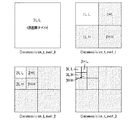
ここで、コード・ブロック単位の画像の動き量(速度)の推定について説明する。前述したように、コード・ブロックとはサブバンドを更に細かいブロックに分けたものである。すなわち、コード・ブロックはサブブロックである。本実施の形態においては、画像の横エッジが強く現われるWavelet変換係数の1階層の1LH成分と、画像の縦エッジが強く現われるWavelet変換係数の1階層の1HL成分とを比較することによって、インターレース画像の動き量(速度)の推定を行うものである。さらには、復号されたときに同じ位置になるコード・ブロックを比較することによってコード・ブロック単位の画像の動き量(速度)の推定を行うものである。ここで、図14は4つのコード・ブロックがある1階層のサブバンドを示すものである。すなわち、図14に示すように、復号時には同じ位置になるコード・ブロック1HL_1とコード・ブロック1LH_1とを比較する。同様に、1HL_2と1LH_2、1HL_3と1LH_3、1HL_4と1LH_4の比較も行う。なお、コード・ブロックが1つのサブバンドの場合には、コード・ブロック単位ではなくサブバンド単位で比較を行う。そして、この比較結果に応じてコード・ブロック単位の画像の動き量(速度)の推定を行う。
【0062】
上述したようなコード・ブロック単位の画像の動き量(速度)の推定処理について、図15に示すフローチャートを参照しつつ説明する。図15に示すように、ブロック選択部51で選択されたコード・ブロックのうち、初めのコード・ブロックを取得し(ステップS1:サブブロック取得手段)、当該コード・ブロックの1LH,1HLのビットプレーンを削る前の符号量をそれぞれ算出し(ステップS2,S3:符号量算出手段)、割り算(1LH/1HL)し、算出された割合を動き量推定の特徴量(rate)とする(ステップS4)。このステップS1〜S4の処理は、特徴量算出部52により実行される。
【0063】
そして、割り算(1LH/1HL)の結果(rate)を閾値(th0)と比較して(ステップS5)、割り算(1LH/1HL)の結果(rate)が閾値(th0)よりも大きければ(ステップS5のY)、画像の横エッジが強く現われているものとして、コード・ブロック単位の画像の動き量(速度)は高速であると推定する(ステップS6)。一方、割り算(1LH/1HL)の結果(rate)が閾値(th0)よりも大きくなければ(ステップS5のN)、画像の縦エッジが強く現われているものとして、コード・ブロック単位の画像の動き量(速度)は低速であると推定する(ステップS7)。このステップS5〜S7の処理は、速度判定部53により実行される。ここに、サブブロック動き量推定手段の機能が実行される。
【0064】
ステップS2〜S7の処理は、ブロック選択部51で選択された全てのコード・ブロックについて終了する迄(ステップS8、S9)、繰り返される。
【0065】
すなわち、図14に示すような1階層のサブバンドに4つのコード・ブロックがある場合には、1階層の係数のコード・ブロックの数だけ上記の処理が繰り返されることになるので、4つのコード・ブロックについての速度が推定されることになる。ここで、1階層のコード・ブロックの数とは、例えばコード・ブロックのサイズが32×32である場合、1LHの係数のサイズが256×128ならば、コード・ブロックの数は(256/32)×(128/32)=8×4=32個である。
【0066】
ここに、高周波サブバンドに含まれるサブブロックの符号量がブロック単位で算出され、このサブブロックの符号量に基づいてコード・ブロック単位での動き量が推定される。これにより、フレーム間差分をとる必要がないことからメモリ消費を抑制するとともに処理時間を短縮することが可能になるので、高速かつ精度良くコード・ブロック単位での動き量を推定することが可能になる。
【0067】
なお、このように推定したコード・ブロック単位での動き量(速度)は、速度推定部41からマスキング制御部44に送られることにより、動きの速い物体と動きの遅い物体が混在している画像に対して、各々最適な処理(マスキング処理など)を施すことができる。
【0068】
次に、本発明の第二の実施の形態について図16ないし図18に基づいて説明する。なお、第一の実施の形態において説明した部分と同一部分については同一符号を用い、説明も省略する。第一の実施の形態では、コード・ブロック単位の画像の動き量(速度)を推定したが、本実施の形態は、コード・ブロック単位の画像の動き量(速度)とフレーム画像全体の動き量(速度)とを推定するものである。
【0069】
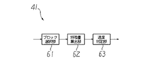
図16は、本発明の第二の実施の形態の速度推定部41の構成を概略的に示すブロック図である。図16に示すように、速度推定部41は、ブロック選択部61、特徴量算出部62、速度判定部63の各部から構成される。ブロック選択部61は、演算すべきコード・ブロックを選択するものである。例えば、1階層のサブバンド1LHの中のコード・ブロックをラスター順に選択する。または、全てのコード・ブロックを選択する構成にしても良い。特徴量算出部62は、ブロック選択部61で選択されたコード・ブロックの係数または符号量の演算を行い、特徴量を算出するものである。速度判定部63は、特徴量算出部62で求められた特徴量を用いて、コード・ブロック単位の画像の動き量(速度)とフレーム画像全体の動き量(速度)とを推定するものである。
【0070】
コード・ブロック単位の画像の動き量(速度)の推定については、第一の実施の形態で説明したので、その説明は省略する。
【0071】
次に、コード・ブロック単位の画像の動き量(速度)の推定結果を利用したフレーム画像全体の動き量(速度)の推定について説明する。なお、第一の実施の形態で説明したように、コード・ブロック単位の画像の動き量(速度)が4つのコード・ブロックについて推定されていることを前提として説明する。
【0072】
本実施の形態においては、フレーム画像全体の動き量(速度)を各コード・ブロック単位の画像の動き量(速度)の比率に応じて推定するものである。より具体的には、図17に示すように、4つのコード・ブロックについての画像の動き量(速度)の高速と低速の比率が、
高速:低速=3:1
であれば、高速の比率が高いことからフレーム画像全体の動き量(速度)は高速であると推定する。
【0073】
なお、これはあくまでも一例であり、コード・ブロック単位の画像の動き量(速度)の推定結果を用いて、フレーム画像全体の動き量(速度)を高速に判定しやすくするか、低速に判定しやすくするかは、自由に設定できる構成にしても良い。
【0074】
上述したようなコード・ブロック単位の画像の動き量(速度)及びフレーム画像全体の動き量(速度)の推定処理について、図18に示すフローチャートを参照しつつ説明する。図18に示すように、カウンタの初期化(ステップS21)やブロック選択部51で選択されたコード・ブロックの総数を設定(ステップS22)した後、対応するコード・ブロック毎に1LH,1HLのビットプレーンを削る前の符号量をそれぞれ算出し(ステップS23,S24)、割り算(1LH/1HL)を行う(ステップS25)。
【0075】
そして、割り算(1LH/1HL)の結果(rate)を閾値(th1)と比較して(ステップS26)、割り算(1LH/1HL)の結果(rate)が閾値(th1)よりも大きければ(ステップS26のY)、割り算(1LH/1HL)の結果(rate)が閾値(th1)よりも大きいコード・ブロックの数をカウントする(ステップS27)。
【0076】
ステップS23〜S27の処理は、ブロック選択部51で選択された全てのコード・ブロックについて終了する迄、繰り返される。
【0077】
ブロック選択部51で選択された全てのコード・ブロックについてステップS23〜S27の処理が終了すると(ステップS28のY)、割り算(1LH/1HL)の結果(rate)が閾値(th1)よりも大きいコード・ブロックの数を総コード・ブロック数で割り算し、算出された割合を動き量推定の特徴量(speed)とする(ステップS29)。このステップS21〜S29の処理は、特徴量算出部52により実行される。
【0078】
そして、特徴量算出部52で求められた特徴量(speed)と閾値(th2)とを比較し(ステップS30)、その比較結果に基づいて高速、低速の判定をする。すなわち、特徴量算出部52で求められた特徴量(speed)が閾値(th2)よりも大きければ(ステップS30のY)、各コード・ブロックにおける画像の動き量(速度)の高速の比率が高いものとして、フレーム画像全体の動き量(速度)は高速であると推定する(ステップS31)。一方、特徴量算出部52で求められた特徴量(speed)が閾値(th2)よりも大きくなければ(ステップS30のN)、各コード・ブロックにおける画像の動き量(速度)の低速の比率が高いものとして、フレーム画像全体の動き量(速度)は低速であると推定する(ステップS32)。このステップS30〜S32の処理は、速度判定部53により実行される。ここに、フレーム動き量推定手段の機能が実行される。
【0079】
ここに、高周波サブバンドに含まれるサブブロックの符号量がブロック単位で算出され、このサブブロックの符号量に基づいてコード・ブロック単位での動き量が推定されるとともに、この推定されたサブブロック単位の動き量に基づいてフレーム全体の動き量が推定される。このように推定したフレーム全体の動き量(速度)は、速度推定部41から量子化テーブル決定部42に送られることにより、量子化テーブル決定部42では動き量(速度)に適した量子化テーブルを選択することができる。つまり、フレーム全体の動き量によって画質の粗調整を行い、コード・ブロック毎の動き量によって画質の微調整を行うことが可能になるので、効率の良い画質制御を行うことが可能になる。
【0080】
また、前述の説明では、本発明の画像記録装置1aをムービーカメラに適用した例を説明したが、画像記録装置1aを携帯情報端末装置(PDA)、携帯電話などの情報端末装置に適用することもできる。
【0081】
【発明の効果】
本発明によれば、次のような効果が得られる。
(1)高周波サブバンドに含まれるサブブロックの符号量をブロック単位で算出し、このサブブロックの符号量に基づいてコード・ブロック単位での動き量を推定することにより、フレーム間差分をとる必要がないことからメモリ消費を抑制するとともに処理時間を短縮することができるので、高速かつ精度良くコード・ブロック単位での動き量を推定することができる。特に、画像の横エッジが強く現われるウェーブレット変換係数の1階層の1LH成分と、画像の縦エッジが強く現われるウェーブレット変換係数の1階層の1HL成分とを比較することで、インターレース画像の動き量(速度)を確実に推定することができる。
【0082】
(2)推定されたサブブロック単位の動き量に基づいてフレーム全体の動き量を推定することにより、フレーム全体の動き量によって画質の粗調整を行い、コード・ブロック毎の動き量によって画質の微調整を行うことができるので、効率の良い画質制御を行うことができる。しかも、高周波サブバンドに含まれる全てのサブブロックについての前記サブブロック動き量推定手段によるサブバンド1LHの符号量とサブバンド1HLの符号量との比較結果の比率に応じてフレーム画像全体の動き量を推定することにより、フレーム画像全体の動き量を簡易に推定することができる。
【0083】
(3)サブブロックの符号量は、ロスレス圧縮された符号量であることにより、動き量の推定精度の向上を図ることができる。
【0084】
(4)サブブロックの符号量は、ビットトランケーション前の符号量であることにより、動き量の推定精度の向上を図ることができる。
【図面の簡単な説明】
【図1】本発明の前提となるJPEG2000方式の基本となる階層符号化アルゴリズムを実現するシステムの機能ブロック図である。
【図2】原画像の各コンポーネントの分割された矩形領域を示す説明図である。
【図3】デコンポジション・レベル数が3の場合の、各デコンポジション・レベルにおけるサブバンドを示す説明図である。
【図4】プレシンクトを示す説明図である。
【図5】ビットプレーンに順位付けする手順の一例を示す説明図である。
【図6】符号列データの1フレーム分の概略構成を示す説明図である。
【図7】Motion JPEG2000の概念を示す説明図である。
【図8】本発明の第一の実施の形態のムービーカメラシステムの概略構成を示すブロック図である。
【図9】画像記録装置のハードウエア構成の一例を示すブロック図である。
【図10】画像圧縮装置の構成を概略的に示すブロック図である。
【図11】ポスト量子化部の構成を概略的に示すブロック図である。
【図12】速度推定部による画像の動き量(速度)の推定手法の基本的思想についての説明図である。
【図13】速度推定部の構成を概略的に示すブロック図である。
【図14】4つのコード・ブロックがある1階層のサブバンドを示す説明図である。
【図15】コード・ブロック単位の画像の動き量(速度)の推定処理の流れを示すフローチャートである。
【図16】本発明の第二の実施の形態の速度推定部の構成を概略的に示すブロック図である。
【図17】コード・ブロック単位の画像の動き量(速度)の推定結果の一例を示す説明図である。
【図18】コード・ブロック単位の画像の動き量(速度)及びフレーム画像全体の動き量(速度)の推定処理の流れを示すフローチャートである。
【符号の説明】
12 記憶媒体
41 動き量推定装置[0001]
BACKGROUND OF THE INVENTION
The present invention relates to a motion estimation device, a program, a storage medium, and a motion estimation method.
[0002]
[Prior art]
Due to advances in image input technology and output technology, the demand for higher definition of images has increased greatly in recent years. For example, taking a digital camera as an example of an image input device, the price of a high-performance charge-coupled device (CCD) having a number of pixels of 3 million or more has been reduced, and the price range has become widespread. It has come to be widely used in products. And the product of 5 million pixels is coming soon. And it is said that this increasing trend in the number of pixels will continue for a while.
[0003]
On the other hand, with regard to image output / display devices, for example, products in the hard copy field such as laser printers, ink jet printers, sublimation printers, and flats such as CRTs, LCDs (liquid crystal display devices), and PDPs (plasma display devices). The high definition and low price of products in the soft copy field of panel displays are remarkable.
[0004]
Due to the market launch of these high-performance, low-priced image input / output products, high-definition images have become popular, and it is expected that demand for high-definition images will increase in all situations. In fact, the development of technology related to networks such as personal computers and the Internet is accelerating these trends. In particular, recently, mobile devices such as mobile phones and notebook personal computers have become very popular, and opportunities for transmitting or receiving high-definition images from any point using communication means are rapidly increasing.
[0005]
Against this background, it is inevitable that the demand for higher performance or higher functionality for image compression / decompression technology that facilitates the handling of high-definition images will become stronger in the future.
[0006]
Therefore, in recent years, a new method called JPEG2000, which can restore high-quality images even at a high compression rate, is being standardized as one of image compression methods that satisfy these requirements. In JPEG2000, it is possible to perform compression / decompression processing in a small memory environment by dividing an image into rectangular regions (tiles). That is, each tile becomes a basic unit for executing the compression / decompression process, and the compression / decompression operation can be performed independently for each tile.
[0007]
Further, such a JPEG 2000 image of one frame can be converted into a moving image by being continuously displayed at a predetermined frame rate (the number of frames reproduced per unit time). As a standard for moving a JPEG2000 image frame by frame and displaying a moving image, there is an international standard called Motion JPEG2000.
[0008]
In addition, as in the Motion JPEG2000 system, there has also been proposed one in which image data is compression-coded using discrete wavelet transform (see, for example, Patent Document 1).
[0009]
In the technique disclosed in
[0010]
[Patent Document 1]
JP 2001-309281 A
[0011]
[Problems to be solved by the invention]
However, according to the method described in
[0012]
An object of the present invention is to provide a motion amount estimation device, a program, a storage medium, and a motion amount estimation method capable of obtaining a motion amount of an image with high speed and accuracy.
[0013]
[Means for Solving the Problems]
The motion amount estimation apparatus according to the first aspect of the present invention is hierarchically compression-coded by dividing into a plurality of blocks for each frame of an interlaced image constituting a moving image and subjecting pixel values to discrete wavelet transform for each block. Means for selecting subblocks corresponding to high-frequency subbands of the LH component (1LH) and HL component (1HL) of one layer from the code string data, and the code amount of the selected 1LH subblock, The code amount of the 1HL sub-block is calculated, and a ratio between the two (1LH code amount / 1HL code amount) is calculated, and the calculated ratio is compared with a threshold value.Sub-blockThe amount of motion is estimated to be fast,Sub-blockAnd a means for estimating that the amount of motion is low.
[0014]
High frequency subbandThe code amount of the sub-block included in the block is calculated in block units, and based on the code amount of this sub-block, code block unitetcThe amount of motion at is estimated. As a result, it is not necessary to take the difference between frames, so it is possible to reduce memory consumption and shorten the processing time.etcIt is possible to estimate the amount of motion at.In particular, by comparing the 1LH component of the first layer of the wavelet transform coefficient where the horizontal edge of the image appears strongly with the 1HL component of the first layer of the wavelet transform coefficient where the vertical edge of the image appears strongly, the motion amount (speed) of the interlaced image ) Is reliably estimated.
[0015]
According to a second aspect of the present invention, in the motion amount estimating apparatus according to the first aspect, the high speed is estimated for the entire frame.Means for dividing the number of sub-blocks or the number of sub-blocks estimated to be low by the total number of sub-blocks, and comparing the result of the division with a threshold value, the amount of motion of the entire frame is high or low Means to estimateIt has further.
[0016]
Therefore, estimatedSub-blockThe motion amount of the entire frame is estimated based on the unit motion amount. As a result, it is possible to perform rough adjustment of image quality based on the amount of motion of the entire frame and fine adjustment of image quality based on the amount of motion for each code block, etc., thus enabling efficient image quality control. . Moreover, since the motion amount of the entire frame image is estimated according to the ratio of the comparison result between the code amount of the subband 1LH and the code amount of the subband 1HL for all subblocks included in the high frequency subband, the entire frame image It is possible to easily estimate the amount of movement.
[0017]
According to a third aspect of the present invention, in the motion amount estimation apparatus according to the first or second aspect, the calculated code amount of the sub-block is a lossless compressed code amount. Therefore, it is possible to improve the estimation accuracy of the motion amount.
[0018]
According to a fourth aspect of the present invention, in the motion amount estimation apparatus according to any one of the first to third aspects, the calculated code amount of the sub-block is a code amount before bit truncation. did Accordingly, it is possible to improve the estimation accuracy of the motion amount.
[0019]
A fifth aspect of the present invention is a program that causes a computer to execute the function of each unit of the motion amount estimating apparatus according to any one of the first to fourth aspects. A sixth aspect of the present invention is a computer-readable storage medium storing a program that causes a computer to execute the function of each means of the motion amount estimating apparatus according to any one of the first to fourth aspects. Therefore, it is possible to obtain the same operation as in the first to fourth aspects by executing the program directly on the computer or by reading the program recorded on the storage medium into the computer and executing it.
[0020]
The motion amount estimation method according to the invention of
[0021]
The invention according to claim 8 is the motion amount estimation method according to
[0022]
According to a ninth aspect of the present invention, in the motion amount estimation according to the seventh or eighth aspect, the calculated code amount of the sub-block is a lossless compressed code amount. Therefore, it is possible to obtain the same effect as that of the third aspect.
[0023]
According to a tenth aspect of the present invention, in the motion amount estimation method according to any one of the seventh to ninth aspects, the calculated code amount of the sub-block is a code amount before bit truncation. Therefore, it is possible to obtain the same effect as that of the fourth aspect.
[0024]
DETAILED DESCRIPTION OF THE INVENTION
First, an outline of the “hierarchical encoding algorithm” and the “JPEG2000 algorithm” that are the premise of the present embodiment will be described.
[0025]
FIG. 1 is a functional block diagram of a system that realizes a hierarchical encoding algorithm that is the basis of the JPEG2000 system. This system includes color space transform /
[0026]
One of the biggest differences between this system and the conventional JPEG algorithm is the conversion method. In JPEG, discrete cosine transform (DCT) is used, whereas in this hierarchical coding algorithm, the two-dimensional wavelet transform /
[0027]
Another major difference is that in this hierarchical encoding algorithm, a functional block of the
[0028]
In many cases, color space conversion /
[0029]
Next, the JPEG2000 algorithm will be described.
[0030]
As shown in FIG. 2, in a color image, each component 111 (RGB primary color system here) of an original image is generally divided by a rectangular area. This divided rectangular area is generally called a block or a tile. In JPEG2000, it is generally called a tile. Therefore, such a divided rectangular area is hereinafter referred to as a tile. (In the example of FIG. 2, each component 111 is divided into a total of 16
[0031]
At the time of encoding image data, the data of each
[0032]
FIG. 3 shows subbands at each decomposition level when the number of decomposition levels is three. In other words, the tile original image (0LL) (decomposition level 0) obtained by tile division of the original image is subjected to two-dimensional wavelet transform, and the subbands (1LL, 1HL, 1LH shown in the decomposition level 1) , 1HH). Subsequently, the low-frequency component 1LL in this hierarchy is subjected to two-dimensional wavelet transformation to separate the subbands (2LL, 2HL, 2LH, 2HH) indicated by the
[0033]
Next, the bits to be encoded are determined in the specified encoding order, and the context is generated from the bits around the target bits by the quantization /
[0034]
The wavelet coefficients that have undergone the quantization process are divided into non-overlapping rectangles called “precincts” for each subband. This was introduced to use memory efficiently in implementation. As shown in FIG. 4, one precinct consists of three rectangular regions that are spatially coincident. Further, each precinct is divided into non-overlapping rectangular “code blocks”. This is the basic unit for entropy coding.
[0035]
The coefficient values after the wavelet transform can be quantized and encoded as they are, but in JPEG2000, in order to increase the encoding efficiency, the coefficient values are decomposed into “bit plane” units, and each pixel or code block is divided. Ranking can be performed on “bitplanes”.
[0036]
Here, FIG. 5 is an explanatory diagram showing an example of a procedure for ranking the bit planes. As shown in FIG. 5, this example is a case where the original image (32 × 32 pixels) is divided into four 16 × 16 pixel tiles, and the size of the precinct and code block at the
[0037]
An explanatory diagram showing an example of the concept of a typical “layer” configuration for
[0038]
The layer structure is easy to understand when the wavelet coefficient values are viewed from the horizontal direction (bit plane direction). One layer is composed of an arbitrary number of bit planes. In this example, layers 0, 1, 2, and 3 are made up of bit planes of 1, 3, 1, and 3, respectively. A layer including a bit plane closer to the LSB (Least Significant Bit) is subject to quantization first, and conversely, a layer close to the MSB (Most Significant Bit: most significant bit) is quantized to the end. It will remain without being. A method of discarding from a layer close to the LSB is called truncation, and the quantization rate can be finely controlled.
[0039]
The entropy encoding /
[0040]
FIG. 6 shows a schematic configuration for one frame of the code string data. The head of this code string data and the head of the code data (bit stream) of each tile are a header (a main header (tile header) that is tile boundary position information, tile boundary direction information, and the like). Is added, followed by encoded data for each tile. Note that the main header (Main header) describes coding parameters and quantization parameters. A tag (end of codestream) is placed again at the end of the code string data.
[0041]
On the other hand, at the time of decoding, the image data is generated from the code string data of each
[0042]
The above is an outline of the “JPEG2000 algorithm”. A “motion JPEG2000 algorithm” is an extension of a still image, that is, a method for a single frame to a plurality of frames. That is, “Motion JPEG2000”, as shown in FIG. 7, is a moving image by continuously displaying a JPEG2000 image of one frame at a predetermined frame rate (the number of frames reproduced per unit time). .
[0043]
Hereinafter, a first embodiment of the present invention will be described. Here, an example relating to a moving image compression / decompression technique typified by Motion JPEG 2000 will be described, but it goes without saying that the present invention is not limited to the contents of the following description.
[0044]
FIG. 8 is a block diagram showing a schematic configuration of a
[0045]
In the following, an image recording apparatus 1a that exhibits the characteristic functions of the present invention will be described. The moving image playback apparatus 1b may be a standard system capable of decompressing code string data compressed by the Motion JPEG2000 method, and thus detailed description thereof is omitted.
[0046]
As shown in FIG. 8, the image recording device 1a includes an
[0047]
FIG. 9 is a block diagram illustrating an example of a hardware configuration of the image recording apparatus 1a. As shown in FIG. 9, the image recording apparatus 1 a includes a CPU (Central Processing Unit) 11 that is a main part of a computer and controls each part centrally. The CPU 11 includes various ROMs (Read Only). A
[0048]
In the image recording apparatus 1 a, in addition to the
[0049]
Control programs such as a moving image processing program for processing moving images are stored in the memory 12 (ROM) of the image recording apparatus 1a having such a configuration. This moving image processing program implements the program of the present invention. And the function of the
[0050]
As the
[0051]
Here, the operation of each part of the image recording apparatus 1a will be briefly described. The
[0052]
The
[0053]
Next, the operation of each part constituting the
[0054]
Here, the
[0055]
The
[0056]
The masking
[0057]
The quantization
[0058]
The
[0059]
Here, a method for estimating the amount of motion (speed) of the image by the
[0060]
FIG. 13 is a block diagram schematically showing the configuration of the
[0061]
Here, estimation of the motion amount (speed) of the image in units of code blocks will be described. As described above, the code block is a subband divided into finer blocks. That is, the code block is a sub-block. In the present embodiment, the interlaced image is compared by comparing the 1LH component of the first layer of the Wavelet transform coefficient in which the horizontal edge of the image appears strongly with the 1HL component of the first layer of the Wavelet transform coefficient in which the vertical edge of the image appears strongly. The amount of motion (speed) is estimated. Further, the motion amount (speed) of the image in units of code blocks is estimated by comparing code blocks that are in the same position when decoded. Here, FIG. 14 shows a one-layer subband having four code blocks. That is, as shown in FIG. 14, the code block 1HL_1 and the code block 1LH_1 that are at the same position during decoding are compared. Similarly, 1HL_2 and 1LH_2, 1HL_3 and 1LH_3, and 1HL_4 and 1LH_4 are also compared. When the code block is one subband, the comparison is performed in units of subbands instead of units of code blocks. Then, the amount of motion (speed) of the image in units of code blocks is estimated according to the comparison result.
[0062]
The process for estimating the amount of motion (speed) of the image in units of code blocks as described above will be described with reference to the flowchart shown in FIG. As shown in FIG. 15, among the code blocks selected by the
[0063]
Then, the result (rate) of the division (1LH / 1HL) is compared with the threshold (th0) (step S5), and if the result (rate) of the division (1LH / 1HL) is larger than the threshold (th0) (step S5). Y) Assuming that the horizontal edge of the image appears strongly, the motion amount (speed) of the image in units of code blocks is estimated to be high (step S6). On the other hand, if the result (rate) of the division (1LH / 1HL) is not larger than the threshold (th0) (N in step S5), it is assumed that the vertical edge of the image appears strongly, and the motion of the image in units of code blocks The amount (speed) is estimated to be low (step S7). The processing in steps S5 to S7 is executed by the
[0064]
The processes in steps S2 to S7 are repeated until all the code blocks selected by the
[0065]
That is, when there are four code blocks in one layer subband as shown in FIG. 14, the above process is repeated for the number of code blocks of the coefficient in one layer. • The speed for the block will be estimated. Here, the number of code blocks in one layer is, for example, when the size of a code block is 32 × 32 and the size of a 1LH coefficient is 256 × 128, the number of code blocks is (256/32). ) × (128/32) = 8 × 4 = 32.
[0066]
Here, the code amount of the subblock included in the high frequency subband is calculated in units of blocks, and the amount of motion in units of code blocks is estimated based on the code amount of the subblocks. As a result, it is not necessary to take the difference between frames, so it is possible to reduce memory consumption and reduce the processing time, so it is possible to estimate the amount of motion in units of code blocks with high speed and accuracy. Become.
[0067]
The motion amount (speed) in units of code blocks estimated in this way is sent from the
[0068]
Next, a second embodiment of the present invention will be described with reference to FIGS. The same parts as those described in the first embodiment are denoted by the same reference numerals, and description thereof is also omitted. In the first embodiment, the motion amount (speed) of the image in units of code blocks is estimated. However, in this embodiment, the motion amount (speed) of the image in units of code blocks and the motion amount of the entire frame image are estimated. (Speed) is estimated.
[0069]
FIG. 16 is a block diagram schematically showing the configuration of the
[0070]
Since the estimation of the motion amount (speed) of the image in units of code blocks has been described in the first embodiment, the description thereof is omitted.
[0071]
Next, estimation of the motion amount (speed) of the entire frame image using the estimation result of the motion amount (speed) of the image in units of code blocks will be described. Note that, as described in the first embodiment, the description will be made on the assumption that the motion amount (speed) of an image in units of code blocks is estimated for four code blocks.
[0072]
In the present embodiment, the motion amount (speed) of the entire frame image is estimated according to the ratio of the motion amount (speed) of the image for each code block unit. More specifically, as shown in FIG. 17, the ratio between the high speed and the low speed of the motion amount (speed) of the image for the four code blocks is
High speed: Low speed = 3: 1
Then, since the high-speed ratio is high, it is estimated that the motion amount (speed) of the entire frame image is high.
[0073]
Note that this is just an example, and using the estimation result of the motion amount (speed) of the image in units of code blocks, it is easy to determine the motion amount (speed) of the entire frame image at a high speed or a low speed. It may be configured so that it can be easily set.
[0074]
The process of estimating the amount of motion (speed) of the image in units of code blocks and the amount of motion (speed) of the entire frame image as described above will be described with reference to the flowchart shown in FIG. As shown in FIG. 18, after initializing the counter (step S21) and setting the total number of code blocks selected by the block selection unit 51 (step S22), 1LH and 1HL bits for each corresponding code block The code amount before cutting the plane is calculated (steps S23 and S24), and division (1LH / 1HL) is performed (step S25).
[0075]
Then, the result (rate) of the division (1LH / 1HL) is compared with the threshold (th1) (step S26), and if the result (rate) of the division (1LH / 1HL) is larger than the threshold (th1) (step S26). Y), the number of code blocks whose count (1LH / 1HL) result (rate) is greater than the threshold (th1) is counted (step S27).
[0076]
The processes in steps S23 to S27 are repeated until all the code blocks selected by the
[0077]
When the processing of steps S23 to S27 is completed for all code blocks selected by the block selection unit 51 (Y in step S28), the code whose division (1LH / 1HL) result (rate) is greater than the threshold (th1) The number of blocks is divided by the total number of codes and the number of blocks, and the calculated ratio is set as a feature amount (speed) for motion amount estimation (step S29). The processes in steps S21 to S29 are executed by the feature
[0078]
Then, the feature amount (speed) obtained by the feature
[0079]
Here, the code amount of the sub-block included in the high frequency sub-band is calculated in block units, and the motion amount in code block unit is estimated based on the code amount of the sub-block, and the estimated sub-block The motion amount of the entire frame is estimated based on the unit motion amount. The motion amount (speed) of the entire frame estimated in this way is sent from the
[0080]
In the above description, the image recording apparatus 1a of the present invention is applied to a movie camera. However, the image recording apparatus 1a is applied to an information terminal apparatus such as a personal digital assistant (PDA) or a mobile phone. You can also.
[0081]
【The invention's effect】
According to the present invention, the following effects can be obtained.
(1) It is necessary to calculate inter-frame differences by calculating the code amount of sub-blocks included in the high-frequency subband in units of blocks and estimating the amount of motion in units of code blocks based on the code amounts of the sub-blocks Therefore, the memory consumption can be suppressed and the processing time can be shortened, so that the motion amount in units of code blocks can be estimated with high speed and accuracy. In particular, by comparing the 1LH component of the first layer of the wavelet transform coefficient in which the horizontal edge of the image appears strongly with the 1HL component of the first layer of the wavelet transform coefficient in which the vertical edge of the image appears strongly, the motion amount (speed) of the interlaced image ) Can be reliably estimated.
[0082]
(2) By estimating the motion amount of the entire frame based on the estimated motion amount of each sub-block, the image quality is roughly adjusted by the motion amount of the entire frame, and the image quality is finely adjusted by the motion amount of each code block. Since adjustment can be performed, efficient image quality control can be performed. In addition, the motion amount of the entire frame image according to the ratio of the comparison result between the code amount of the subband 1LH and the code amount of the subband 1HL by the subblock motion amount estimation means for all subblocks included in the high frequency subband. It is possible to easily estimate the amount of motion of the entire frame image.
[0083]
(3) Since the code amount of the sub-block is a lossless-compressed code amount, the motion amount estimation accuracy can be improved.
[0084]
(4) Since the code amount of the sub-block is the code amount before bit truncation, it is possible to improve the estimation accuracy of the motion amount.
[Brief description of the drawings]
FIG. 1 is a functional block diagram of a system that realizes a hierarchical encoding algorithm that is the basis of a JPEG2000 system that is a premise of the present invention.
FIG. 2 is an explanatory diagram showing a divided rectangular area of each component of the original image.
FIG. 3 is an explanatory diagram showing subbands at each decomposition level when the number of decomposition levels is 3. FIG.
FIG. 4 is an explanatory diagram showing a precinct.
FIG. 5 is an explanatory diagram showing an example of a procedure for ranking bit planes;
FIG. 6 is an explanatory diagram illustrating a schematic configuration of one frame of code string data.
FIG. 7 is an explanatory diagram showing the concept of Motion JPEG2000.
FIG. 8 is a block diagram showing a schematic configuration of the movie camera system according to the first embodiment of the present invention.
FIG. 9 is a block diagram illustrating an example of a hardware configuration of an image recording apparatus.
FIG. 10 is a block diagram schematically showing a configuration of an image compression apparatus.
FIG. 11 is a block diagram schematically showing a configuration of a post quantization unit.
FIG. 12 is an explanatory diagram of a basic idea of an image motion amount (speed) estimation method performed by a speed estimation unit;
FIG. 13 is a block diagram schematically showing a configuration of a speed estimation unit.
FIG. 14 is an explanatory diagram showing a one-layer subband having four code blocks;
FIG. 15 is a flowchart showing the flow of estimation processing of the motion amount (speed) of an image in units of code blocks.
FIG. 16 is a block diagram schematically illustrating a configuration of a speed estimation unit according to the second embodiment of this invention.
FIG. 17 is an explanatory diagram illustrating an example of an estimation result of a motion amount (speed) of an image in units of code blocks.
FIG. 18 is a flowchart showing a flow of estimation processing of the motion amount (speed) of an image in units of code blocks and the motion amount (speed) of the entire frame image.
[Explanation of symbols]
12 storage media
41 Motion estimation device
Claims (10)
前記選択された1LHのサブブロックの符号量と1HLのサブブロックの符号量とを計算して、両者の比率(1LHの符号量/1HLの符号量)を算出する手段と、
前記算出された比率を閾値と比較して、大きければ当該サブブロックの動き量は高速であると推定し、大きくなけば当該サブブロックの動き量は低速であると推定する手段と、
を有することを特徴とする動き量推定装置。One layer of LH components (1LH) is obtained from code string data that is hierarchically compression-coded by dividing the block into a plurality of blocks for each interlaced image frame constituting the moving image and subjecting the pixel values to discrete wavelet transform for each block. ) And means for selecting a sub-block corresponding to the high-frequency sub-band of the HL component (1HL) in units of blocks,
Means for calculating a code amount of the selected 1LH sub-block and a code amount of the 1HL sub-block, and calculating a ratio between the two (a code amount of 1LH / a code amount of 1HL);
A means for comparing the calculated ratio with a threshold and estimating that the motion amount of the sub-block is high if it is large, and estimating that the motion amount of the sub-block is low if it is not large;
A motion amount estimation apparatus comprising:
前記除算した結果を閾値と比較して、当該フレーム全体の動き量が高速あるいは低速であると推定する手段と、
を更に有することを特徴とする請求項1記載の動き量推定装置。 Means for dividing the number of sub-blocks estimated to be fast or the number of sub-blocks estimated to be slow by the total number of sub-blocks in the entire frame ;
Means for comparing the result of the division with a threshold and estimating that the amount of motion of the entire frame is high or low;
The motion amount estimation apparatus according to claim 1 , further comprising:
前記選択された1LHのサブブロックの符号量と1HLのサブブロックの符号量とを計算して、両者の比率(1LHの符号量/1HLの符号量)を算出するステップと、
前記算出された比率を閾値と比較して、大きければ当該サブブロックの動き量は高速であると推定し、大きくなけば当該サブブロックの動き量は低速であると推定するステップと、
を有することを特徴とする動き量推定方法。One layer of LH components (1LH) is obtained from code string data that is hierarchically compression-coded by dividing the block into a plurality of blocks for each interlaced image frame constituting the moving image and subjecting the pixel values to discrete wavelet transform for each block. ) And a sub-block corresponding to the high-frequency sub-band of the HL component (1HL) are selected in units of blocks;
Calculating a code amount of the selected 1LH sub-block and a code amount of the 1HL sub-block, and calculating a ratio between the two (a code amount of 1LH / a code amount of 1HL);
Comparing the calculated ratio with a threshold, estimating that the amount of motion of the sub-block is fast if it is large, and estimating that the amount of motion of the sub-block is slow if not large;
A motion amount estimation method characterized by comprising:
前記除算した結果を閾値と比較して、当該フレーム全体の動き量が高速あるいは低速であると推定するステップと、
を更に有することを特徴とする請求項7記載の動き量推定方法。 Dividing the number of sub-blocks estimated to be fast or the number of sub-blocks estimated to be slow by the total number of sub-blocks over the entire frame ;
Comparing the result of the division with a threshold and estimating that the amount of motion of the entire frame is high or low;
The motion amount estimation method according to claim 7, further comprising:
Priority Applications (3)
| Application Number | Priority Date | Filing Date | Title |
|---|---|---|---|
| JP2002329553A JP4124436B2 (en) | 2002-11-13 | 2002-11-13 | Motion estimation device, program, storage medium, and motion estimation method |
| US10/678,696 US7450768B2 (en) | 2002-10-02 | 2003-10-02 | Apparatus and method for processing image data based on object movement speed within a frame |
| US12/234,451 US8000542B2 (en) | 2002-10-02 | 2008-09-19 | Apparatus and method for processing image data based on object movement speed within a frame |
Applications Claiming Priority (1)
| Application Number | Priority Date | Filing Date | Title |
|---|---|---|---|
| JP2002329553A JP4124436B2 (en) | 2002-11-13 | 2002-11-13 | Motion estimation device, program, storage medium, and motion estimation method |
Publications (3)
| Publication Number | Publication Date |
|---|---|
| JP2004165982A JP2004165982A (en) | 2004-06-10 |
| JP2004165982A5 JP2004165982A5 (en) | 2005-10-13 |
| JP4124436B2 true JP4124436B2 (en) | 2008-07-23 |
Family
ID=32807510
Family Applications (1)
| Application Number | Title | Priority Date | Filing Date |
|---|---|---|---|
| JP2002329553A Expired - Fee Related JP4124436B2 (en) | 2002-10-02 | 2002-11-13 | Motion estimation device, program, storage medium, and motion estimation method |
Country Status (1)
| Country | Link |
|---|---|
| JP (1) | JP4124436B2 (en) |
Families Citing this family (3)
| Publication number | Priority date | Publication date | Assignee | Title |
|---|---|---|---|---|
| JP4911557B2 (en) * | 2004-09-16 | 2012-04-04 | 株式会社リコー | Image display device, image display control method, program, and information recording medium |
| JP5309097B2 (en) * | 2010-08-11 | 2013-10-09 | 日本放送協会 | Motion estimation apparatus and program |
| JP7001383B2 (en) | 2017-07-28 | 2022-01-19 | キヤノン株式会社 | Coding device, coding method, and program |
-
2002
- 2002-11-13 JP JP2002329553A patent/JP4124436B2/en not_active Expired - Fee Related
Also Published As
| Publication number | Publication date |
|---|---|
| JP2004165982A (en) | 2004-06-10 |
Similar Documents
| Publication | Publication Date | Title |
|---|---|---|
| US8000542B2 (en) | Apparatus and method for processing image data based on object movement speed within a frame | |
| JP3922919B2 (en) | Still image expansion apparatus and still image expansion method | |
| JP2005143105A (en) | Digital video compression | |
| JP2007142614A (en) | Image processing apparatus and method, program, and information recording medium | |
| JP3952459B2 (en) | Image processing apparatus, program, storage medium, and image processing method | |
| JP2004254298A (en) | Image processing device, program, and storage medium | |
| JP4124436B2 (en) | Motion estimation device, program, storage medium, and motion estimation method | |
| JP4145086B2 (en) | Image decoding apparatus, image processing apparatus, moving image display system, program, storage medium, and image decoding method | |
| JP4118049B2 (en) | Image processing apparatus and method | |
| JP4111273B2 (en) | Image decoding apparatus, program, storage medium, and image decoding method | |
| JP2002369202A (en) | Image compression device, image expansion device, image compressing method, image expanding method, program and recording medium stored with the program | |
| JP4489474B2 (en) | Image processing apparatus, program, and recording medium | |
| JP4040404B2 (en) | Code string conversion apparatus and method, image processing apparatus, and image recording apparatus | |
| JP2004056260A (en) | Image decoder, image processor, program, recording medium and image decoding method | |
| JP4361755B2 (en) | Moving image processing apparatus, program, storage medium, and moving image processing method | |
| JP2003339047A (en) | Image compression device, image decompression device, image compression/decompression device, image compression method, image decompression method, program, and recording medium recording the program | |
| JP2004336405A (en) | Dynamic image processing apparatus, program, storage medium, and dynamic image processing method | |
| JP3987425B2 (en) | Image decompression apparatus, program, storage medium, and image decompression method | |
| JP4201163B2 (en) | Image processing apparatus, method, program, and recording medium | |
| JP2004096695A (en) | Image processing apparatus, image display device, program, storage medium, and image processing method | |
| JP4067460B2 (en) | Image decoding apparatus, program, storage medium, and image decoding method | |
| JP4010957B2 (en) | Image processing apparatus, program, storage medium, and image forming apparatus | |
| JP4093870B2 (en) | Image processing apparatus, program, and storage medium | |
| JP3961966B2 (en) | Unnecessary part removing apparatus, image processing apparatus, program, storage medium, and unnecessary part removing method | |
| JP2004056632A (en) | Moving picture processing apparatus, dynamic image reproducing apparatus, dynamic image display system, program, storage medium, and dynamic image processing method |
Legal Events
| Date | Code | Title | Description |
|---|---|---|---|
| RD04 | Notification of resignation of power of attorney |
Free format text: JAPANESE INTERMEDIATE CODE: A7424 Effective date: 20041007 |
|
| A521 | Written amendment |
Free format text: JAPANESE INTERMEDIATE CODE: A523 Effective date: 20050601 Free format text: JAPANESE INTERMEDIATE CODE: A821 Effective date: 20050601 |
|
| A621 | Written request for application examination |
Free format text: JAPANESE INTERMEDIATE CODE: A621 Effective date: 20050601 |
|
| RD02 | Notification of acceptance of power of attorney |
Free format text: JAPANESE INTERMEDIATE CODE: A7422 Effective date: 20050601 |
|
| RD05 | Notification of revocation of power of attorney |
Free format text: JAPANESE INTERMEDIATE CODE: A7425 Effective date: 20060925 |
|
| A977 | Report on retrieval |
Free format text: JAPANESE INTERMEDIATE CODE: A971007 Effective date: 20070425 |
|
| A131 | Notification of reasons for refusal |
Free format text: JAPANESE INTERMEDIATE CODE: A131 Effective date: 20070516 |
|
| A521 | Written amendment |
Free format text: JAPANESE INTERMEDIATE CODE: A523 Effective date: 20070717 |
|
| A131 | Notification of reasons for refusal |
Free format text: JAPANESE INTERMEDIATE CODE: A131 Effective date: 20071106 |
|
| A521 | Written amendment |
Free format text: JAPANESE INTERMEDIATE CODE: A523 Effective date: 20071126 |
|
| A02 | Decision of refusal |
Free format text: JAPANESE INTERMEDIATE CODE: A02 Effective date: 20080116 |
|
| A521 | Written amendment |
Free format text: JAPANESE INTERMEDIATE CODE: A523 Effective date: 20080215 |
|
| A911 | Transfer of reconsideration by examiner before appeal (zenchi) |
Free format text: JAPANESE INTERMEDIATE CODE: A911 Effective date: 20080407 |
|
| TRDD | Decision of grant or rejection written | ||
| A01 | Written decision to grant a patent or to grant a registration (utility model) |
Free format text: JAPANESE INTERMEDIATE CODE: A01 Effective date: 20080430 |
|
| A01 | Written decision to grant a patent or to grant a registration (utility model) |
Free format text: JAPANESE INTERMEDIATE CODE: A01 |
|
| A61 | First payment of annual fees (during grant procedure) |
Free format text: JAPANESE INTERMEDIATE CODE: A61 Effective date: 20080501 |
|
| FPAY | Renewal fee payment (event date is renewal date of database) |
Free format text: PAYMENT UNTIL: 20110516 Year of fee payment: 3 |
|
| FPAY | Renewal fee payment (event date is renewal date of database) |
Free format text: PAYMENT UNTIL: 20120516 Year of fee payment: 4 |
|
| FPAY | Renewal fee payment (event date is renewal date of database) |
Free format text: PAYMENT UNTIL: 20120516 Year of fee payment: 4 |
|
| FPAY | Renewal fee payment (event date is renewal date of database) |
Free format text: PAYMENT UNTIL: 20130516 Year of fee payment: 5 |
|
| FPAY | Renewal fee payment (event date is renewal date of database) |
Free format text: PAYMENT UNTIL: 20130516 Year of fee payment: 5 |
|
| LAPS | Cancellation because of no payment of annual fees |