JP4444265B2 - Vehicular radar apparatus and method for manufacturing the same, reference section, and adjustment method of beam emitting direction - Google Patents
Vehicular radar apparatus and method for manufacturing the same, reference section, and adjustment method of beam emitting direction Download PDFInfo
- Publication number
- JP4444265B2 JP4444265B2 JP2006317887A JP2006317887A JP4444265B2 JP 4444265 B2 JP4444265 B2 JP 4444265B2 JP 2006317887 A JP2006317887 A JP 2006317887A JP 2006317887 A JP2006317887 A JP 2006317887A JP 4444265 B2 JP4444265 B2 JP 4444265B2
- Authority
- JP
- Japan
- Prior art keywords
- housing
- fixed
- fixing
- radar apparatus
- reference portion
- Prior art date
- Legal status (The legal status is an assumption and is not a legal conclusion. Google has not performed a legal analysis and makes no representation as to the accuracy of the status listed.)
- Expired - Fee Related
Links
Images


Classifications
-
- G—PHYSICS
- G01—MEASURING; TESTING
- G01S—RADIO DIRECTION-FINDING; RADIO NAVIGATION; DETERMINING DISTANCE OR VELOCITY BY USE OF RADIO WAVES; LOCATING OR PRESENCE-DETECTING BY USE OF THE REFLECTION OR RERADIATION OF RADIO WAVES; ANALOGOUS ARRANGEMENTS USING OTHER WAVES
- G01S7/00—Details of systems according to groups G01S13/00, G01S15/00, G01S17/00
- G01S7/02—Details of systems according to groups G01S13/00, G01S15/00, G01S17/00 of systems according to group G01S13/00
- G01S7/40—Means for monitoring or calibrating
- G01S7/4004—Means for monitoring or calibrating of parts of a radar system
- G01S7/4026—Antenna boresight
- G01S7/4034—Antenna boresight in elevation, i.e. in the vertical plane
-
- G—PHYSICS
- G01—MEASURING; TESTING
- G01S—RADIO DIRECTION-FINDING; RADIO NAVIGATION; DETERMINING DISTANCE OR VELOCITY BY USE OF RADIO WAVES; LOCATING OR PRESENCE-DETECTING BY USE OF THE REFLECTION OR RERADIATION OF RADIO WAVES; ANALOGOUS ARRANGEMENTS USING OTHER WAVES
- G01S7/00—Details of systems according to groups G01S13/00, G01S15/00, G01S17/00
- G01S7/02—Details of systems according to groups G01S13/00, G01S15/00, G01S17/00 of systems according to group G01S13/00
- G01S7/40—Means for monitoring or calibrating
- G01S7/4004—Means for monitoring or calibrating of parts of a radar system
- G01S7/4026—Antenna boresight
- G01S7/403—Antenna boresight in azimuth, i.e. in the horizontal plane
-
- G—PHYSICS
- G01—MEASURING; TESTING
- G01S—RADIO DIRECTION-FINDING; RADIO NAVIGATION; DETERMINING DISTANCE OR VELOCITY BY USE OF RADIO WAVES; LOCATING OR PRESENCE-DETECTING BY USE OF THE REFLECTION OR RERADIATION OF RADIO WAVES; ANALOGOUS ARRANGEMENTS USING OTHER WAVES
- G01S7/00—Details of systems according to groups G01S13/00, G01S15/00, G01S17/00
- G01S7/48—Details of systems according to groups G01S13/00, G01S15/00, G01S17/00 of systems according to group G01S17/00
- G01S7/497—Means for monitoring or calibrating
- G01S7/4972—Alignment of sensor
-
- G—PHYSICS
- G01—MEASURING; TESTING
- G01S—RADIO DIRECTION-FINDING; RADIO NAVIGATION; DETERMINING DISTANCE OR VELOCITY BY USE OF RADIO WAVES; LOCATING OR PRESENCE-DETECTING BY USE OF THE REFLECTION OR RERADIATION OF RADIO WAVES; ANALOGOUS ARRANGEMENTS USING OTHER WAVES
- G01S7/00—Details of systems according to groups G01S13/00, G01S15/00, G01S17/00
- G01S7/52—Details of systems according to groups G01S13/00, G01S15/00, G01S17/00 of systems according to group G01S15/00
- G01S7/52004—Means for monitoring or calibrating
Description
本発明は、車両用レーダ装置およびその製造方法、基準部並びにビームの出射する方向の調整方法に関し、特にビーム軸を調整するための基準面を有する車両用レーダ装置およびその製造方法、基準部並びにビームの出射する方向の調整方法に関する。 The present invention relates to a vehicular radar apparatus, a manufacturing method thereof , a reference section, and a method of adjusting a beam emitting direction , and more particularly to a vehicular radar apparatus having a reference plane for adjusting a beam axis, a manufacturing method thereof , a reference section, and The present invention relates to a method for adjusting a beam emitting direction .
自動車の走行の安全性確保のため、車両用レーダ装置が開発されている。車両用レーダ装置は、ミリ波等の電波やレーザ光等のビームを出射し、他の車両等を検知するための装置である。他の車両等を精度良く検知するためには、ビームの出射方向(ビーム軸)を車両に対し精度良く合わせることが求められている。しかしながら、ビームを出射するアンテナと筐体との取り付け精度によっては、筐体に対するビーム軸の角度がばらついてしまう。そのため、筐体を基準に車両用レーダ装置を車両に取り付けると、車両に対するビーム軸の精度が悪くなる。そこで、特許文献1には、車両用レーダ装置の出荷時にビーム軸と合わせた基準面を設け、車両用レーダ装置を車両に取り付ける際に、基準面を基にビーム軸を合わせる技術が開示されている。
しかしながら、筐体に対するビーム軸のばらつきは±2〜3°程度ある。一方、車両に対しビーム軸は±0.3°程度で合わせることが求められている。このため、特許文献1の技術を用いる際は、多種類の補正用部材(補正を行うための部材)を準備し、基準面がビーム軸と合うように、補正用部材を選択する。このように、多種類の補正用部材を準備し管理する必要がある。
However, the variation of the beam axis with respect to the housing is about ± 2 to 3 °. On the other hand, it is required that the beam axis be aligned with the vehicle at about ± 0.3 °. For this reason, when using the technique of
本発明は、基準面を有する補正用部材の種類を減らすことを目的とする。 An object of the present invention is to reduce the types of correction members having a reference surface.
本発明は、ビームを出射するビーム出射部と、前記ビーム出射部を搭載する筐体と、前記筐体に固定され、複数の基準面となりうる面と、複数の固定面となりうる面と、を有する基準部と、を具備し、前記基準部を前記筐体に固定する際、前記複数の基準面となりうる面のうちいずれの面を基準面とするか及び前記複数の固定面となりうる面のうちいずれの面を固定面とするかにより、前記筐体の前記基準部が固定される面と前記基準面との角度が各々異なることを特徴とする車両用レーダ装置である。本発明によれば、基準部が角度の異なる複数の基準面となりうる面を有しているため、基準部等のビーム軸の角度を補正するための部材の種類を減らすことができる。 The present invention includes a beam emitting unit that emits a beam, a housing on which the beam emitting unit is mounted, a surface that is fixed to the housing and can be a plurality of reference surfaces, and a surface that can be a plurality of fixing surfaces. A reference portion having the reference portion, and when fixing the reference portion to the housing, which of the plurality of reference surfaces can be used as a reference surface and the plurality of fixing surfaces. out by either a fixed surface either surface, the angle between the casing the surface and the reference portion is fixed to the reference surface of a vehicle radar system according to claim each different. According to the present invention, since the reference portion has a surface that can be a plurality of reference surfaces having different angles, the types of members for correcting the angle of the beam axis, such as the reference portion, can be reduced.
上記構成において、前記基準面は、前記ビームの出射する方向と関連している構成とすることができる。この構成によれば、基準面からビーム軸の方向を設定できるためビーム軸の補正がより容易となる。 The said structure WHEREIN: The said reference plane can be set as the structure relevant to the direction which the said beam radiate | emits. According to this configuration, since the direction of the beam axis can be set from the reference plane, the correction of the beam axis becomes easier.
上記構成において、前記基準面の水平方向は、前記ビームの出射する方向と平行である構成とすることができる。この構成によれば、基準面の水平方向がビーム軸の方向のため、ビーム軸の補正がより容易となる。 The said structure WHEREIN: The horizontal direction of the said reference plane can be set as the structure parallel to the direction where the said beam radiate | emits. According to this configuration, since the horizontal direction of the reference plane is the direction of the beam axis, the correction of the beam axis becomes easier.
上記構成において、前記基準部の前記複数の基準面となりうる面は前記固定面となりうる面と接する面を含む構成とすることができる。また、上記構成において、前記基準部の前記複数の基準面となりうる面は前記複数の固定面となりうる面および前記複数の固定面となりうる面に対向する面を含む構成とすることができる。これらの構成によれば、基準部の多くの面を基準面とすることができるため補正用部材の種類を一層減らすことができる。 In the above configuration, the plurality of surfaces that can be a reference plane of the reference portion may be configured to include a surface in contact with the surface that can serve as the fixing surface. In the above structure, the plurality of reference surfaces and become capable surface of the reference portion may be configured to include a surface opposite to the surface which can be a plurality of fixed surface and can become a surface and the plurality of fixed surface. According to these configurations, since many surfaces of the reference portion can be used as reference surfaces, the types of correction members can be further reduced.
上記構成において、前記筐体は前記基準部を固定する複数の面を有し、前記基準部を前記筐体に固定する際、前記複数の基準面となりうる面のうちいずれの面を基準面とするか及び前記複数の固定面となりうる面のうちいずれの面を固定面とするか及び前記複数の面のうちいずれの面に前記基準部を固定するかにより、前記筐体の前記基準部が固定される面と前記基準面との角度が各々異なる構成とすることができる。この構成によれば、筐体の基準部を固定する複数の面のうちいずれの面に基準部を固定するかにより、設定できる基準面を増やすことができる。よって、補正用部材の種類を一層減らすことができる。 In the above configuration, the housing has a plurality of surfaces for fixing the reference portion, and when the reference portion is fixed to the housing, any of the surfaces that can be the plurality of reference surfaces is defined as a reference surface. The reference portion of the housing is determined depending on which one of the surfaces that can become the plurality of fixing surfaces is a fixing surface and on which of the plurality of surfaces is fixed the reference portion. The angle between the fixed surface and the reference surface may be different from each other . According to this configuration, it is possible to increase the number of reference surfaces that can be set depending on which surface among the plurality of surfaces for fixing the reference portion of the housing is fixed. Therefore, the types of correction members can be further reduced.
本発明は、筐体に搭載されたビーム出射部から出射されるビームの出射する方向を測定する工程と、前記ビームの出射する方向に対応し、基準部の複数の基準面となりうる面のうちいずれかが基準面となり前記基準部の複数の固定面となりうる面のうちいずれかが固定面となるように基準部を前記筐体に固定する工程と、を有することを特徴とする車両用レーダ装置の製造方法である。本発明によれば、基準部等のビーム軸の角度を補正用部材の種類を減らすことができる。
The present invention includes a step of measuring a direction in which a beam emitted from a beam emitting unit mounted on a housing is emitted, and a surface corresponding to the direction in which the beam is emitted, and can be a plurality of reference surfaces of a reference unit wherein the one having the steps of any of the plurality of fixed surface and becomes capable plane of the reference surface and Do Ri said reference portion is fixed to the housing of the reference portion so that such a fixing surface, the It is a manufacturing method of a radar device for vehicles. According to the present invention, the types of members for correcting the angle of the beam axis such as the reference portion can be reduced.
本発明によれば、基準部が角度の異なる複数の基準面となりうる面を有しているため、基準面を有する補正用部材の種類を減らすことできる。 According to the present invention, since the reference portion has a surface that can be a plurality of reference surfaces having different angles, the types of correction members having the reference surface can be reduced.
以下、本発明の実施例につき図面を参照に説明する。 Embodiments of the present invention will be described below with reference to the drawings.
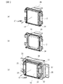
図1(a)は車両用レーダ装置の前面からの斜視図、図1(b)はカバーを外した斜視図、図1(c)はブラケットを設けた斜視図である。図1(a)を参照に、筐体12の前面にアンテナのカバー14が設けられている。図1(b)を参照に、カバー14を外すとアンテナ16(ビーム出射部)が筐体12に搭載されている。図1(a)を参照に、アンテナ16より出射されたミリ波のビームはカバー14を通過し前方に出射される。ビームの出射の中心となる方向がビーム軸Bである。図1(c)を参照に、ブラケット30は車両に車両用レーダ装置10を取り付けるために用いられる。軸調整用ボルト32は車両用レーダ装置10を車両に取り付ける際、ビーム軸Bの方向と車両の正面方向とを精度よく合わせるための調整に用いられる。
1A is a perspective view from the front of the vehicular radar apparatus, FIG. 1B is a perspective view with a cover removed, and FIG. 1C is a perspective view with a bracket. Referring to FIG. 1A, an
図2(a)は車両用レーザ装置の側面図である。筐体12の背面13に基準部20が設けられている。基準部20は固定面23で筐体12にねじ止めされている。基準部20の上面が基準面21となる。図2(b)は車両用レーザ装置10の背面からの斜視図である。筐体12の背面13に基準部20がねじ34により固定されている。
FIG. 2A is a side view of the vehicular laser apparatus. A
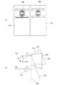
図3は車両50に取り付けた車両用レーダ装置10の斜視図である。車両用レーダ装置10は車両50の前方に取り付けられており、ビーム軸Bは車両50の前方方向となっている。車両用レーザ装置10を車両50に取り付ける際は、まず、ブラケット30を車両50に固定する。その後、図4のように、基準部20の基準面21に水準器40を当接し、軸調整用ボルト32を用い、例えば基準面21が水平になるように調整する。このとき、基準面21の水平方向とビーム軸Bとが平行であれば、ビーム軸Bを水平に設定することができる。このように、車両50に車両用レーダ装置10を取り付ける際、ビームの強度分布を計測しビーム軸Bを調整しなくとも、基準面21に基づき筐体12の取り付け角度を調整することにより、ビーム軸Bを所望の方向に調整することができる。
FIG. 3 is a perspective view of the
図5(a)から図5(d)は基準部20を筐体12の背面13に固定する4つの方法を模式的に示した図である。筐体12の背面13の垂線をK、ビーム軸をB、基準面の水平方向をSで示している。基準として用いる面(基準面)は上方向の面である。図5(a)を参照に、ビーム軸Bが背面13の垂線Kより角度θ1´下向きの場合、基準部21を固定面23で筐体12の背面13に固定し、面21を基準面とする。このとき、基準として用いる基準面21の方向Sは背面13の垂線Kに対し角度θ1下向きとなる。θ1とθ1´がほぼ同じ角度であれば、基準面21の方向Sをビーム軸Bと所望の誤差範囲で平行にすることができる。
FIG. 5A to FIG. 5D are diagrams schematically showing four methods for fixing the
図5(b)を参照に、ビーム軸Bが背面13の垂線Kよりさらに下向きでありその角度がθ2´の場合、基準部20の上下を反対にし面22を基準面とする。これにより、基準面22の方向Sと背面13の垂線Kとの角度をθ1より大きい角度θ2とすることができる。これにより、θ2とθ2´がほぼ同じ角度であれば、基準面21の方向Sをビーム軸Bと所望の誤差範囲で平行にすることができる。
Referring to FIG. 5B, when the beam axis B is further downward from the normal line K of the
図5(c)を参照に、ビーム軸Bが背面13の垂線Kより角度θ1´上向きの場合、基準部20を固定面24で背面13に固定し、面21を基準面とする。これにより、θ1とθ1´がほぼ同じ角度であれば、基準面21の方向Sをビーム軸Bと所望の誤差範囲で平行にすることができる。
Referring to FIG. 5C, when the beam axis B is at an angle θ1 ′ upward from the perpendicular line K of the
図5(d)を参照に、ビーム軸Bが背面13の垂線Kより角度θ2´上向きの場合、基準部20を固定面24で背面13に固定し、面22を基準面とする。これにより、θ2とθ2´がほぼ同じ角度であれば、基準面21の方向Sをビーム軸Bと所望の誤差範囲で平行にすることができる。
Referring to FIG. 5D, when the beam axis B is at an angle θ2 ′ upward from the perpendicular line K of the
実施例1によれば、図5(a)から図5(d)を参照に、筐体12に搭載されたアンテナ16(ビーム出射部)から出射されるビームの出射方向(ビーム軸B)を測定し、ビーム軸Bに対応し、複数の基準となりうる面21および22のうちのいずれかが基準面(上方向の面)となるように基準部20を筐体12に固定する。このように、基準部20を筐体12に固定する際、複数の基準面となりうる面21および22のうちいずれの面を基準面とするかにより、筐体12の基準部20が固定される面と基準面21または22との角度が異なる。これにより、ビーム軸Bの筐体12に対する角度の補正をするための補正用部材の4種類分を基準部20の1種類で行うことができる。よって、部材の種類を削減し、部材の管理工数を削減することができる。
According to the first embodiment, with reference to FIG. 5A to FIG. 5D, the emission direction (beam axis B) of the beam emitted from the antenna 16 (beam emission unit) mounted on the
なお、実施例1では、上方向の面を基準面としているが、予め決めた方向の面を基準面することができる。また、基準部20は筐体12の背面13以外の任意の面(例えば、側面、上面、下面)に固定することもできる。基準面を上方向または下方向とすることにより、ビーム軸Bの車両50の垂直方向(上下方向)のばらつきを補正することができる。同様に、基準面を左方向または右方向に設けることにより、ビーム軸Bの車両50の水平方向(左右方向)のばらつきを補正することができる。このように、ビーム軸Bのいずれの方向のばらつきが車両用レーダ装置の性能に影響を及ぼすかで、基準面をいずれの方向の設けるかを決めることができる。さらに、基準部20に基準面を2つ設け、ビーム軸Bの垂直方向と水平方向の両方のばらつきを補正することもできる。
In the first embodiment, the upper surface is used as the reference surface, but a surface in a predetermined direction can be used as the reference surface. The
実施例1のように、基準面(21または22)の水平方向Sは、ビーム軸B(ビームの出射する方向)とほぼ平行とすることができる。これにより、図4のように、車両50に車両用レーダ装置10を取り付ける際に、基準面の水平方向を車両の所望の方向に合わせることにより、ビーム軸Bを車両に対し所望の方向とすることができる。なお、基準面の方向Sとビーム軸Bとがほぼ平行とは、ビーム軸Bの許容される誤差の範囲で平行との意味である。
As in the first embodiment, the horizontal direction S of the reference surface (21 or 22) can be substantially parallel to the beam axis B (the direction in which the beam is emitted). Thus, as shown in FIG. 4, when the
また、上方向となる基準面21または22は、ビーム軸Bと関連していればよい。例えば、基準面の方向Sとビーム軸Bは、平行でなくとも一定の角度をなしていてもよい。一定の角度を考慮して車両用レーダ装置10を車両50に取り付けることによりビーム軸を所望の方向とすることができる。
Further, the
車両用レーダ装置10は、筐体12に固定され、車両に取り付けるためのブラケット30(取り付け部)を有している。これにより、車両用レーダ装置10を車両50に取り付けることができる。
The
実施例1で車両に車両用レーダ装置10を取り付ける際に、ビーム軸Bを調整するために基準面を用いる方法について説明したが、車両のメンテナンスの際に基準面を用いビーム軸を調整してもよい。
In the first embodiment, the method of using the reference plane to adjust the beam axis B when the
実施例2は筐体12が基準部20を固定する面を複数有する例である。図6(a)は実施例2に係る車両用レーダ装置の背面模式図、図6(b)は側面からみた模式図である。図6(a)を参照に、筐体12は背面として2つの面13a、13bを有している。図6(b)を参照に、面13aの垂線Kaと面13bの垂線Kbとは角度θ3を有している。このため、基準部20を面13aに固定し基準部20aとするか、面13bに固定し基準部20bとするかで、基準面の方向Sの角度が異なる。基準部20aの場合、面13aの垂線Kaに対し基準面21aの方向Saは角度θ1の角度を有している。一方、基準部20bの場合、面13aの垂線Kaに対し基準面21bの方向Sbは角度θ1+θ3の角度を有している。このため、基準面が4つの基準部20を用い、8通りの基準面を設定することができる。このように、筐体12が基準部20を固定する面を複数有することにより、設定できる基準を増やすことができる。よって、部材の種類を一層削減し、部材の管理工数を一層削減することができる。
Example 2 is an example in which the
図7(a)から図7(c)は実施例3の基準部20aを示す図である。なお、筐体に固定するためのねじ孔は図示していない。実施例3においては、例えば面S1を筐体12に固定し(すなわち面S1を固定面とする)、面S2から面S5のいずれかを基準面とすることができる。さらに、面S2を固定面とし、面S1、S3、S5、S6のいずれかを基準面とすることもできる。このように、面S1からS6のいずれかを固定面とし、固定面に接続する面のいずれかを基準面とすることができる。つまり、実施例3では6個の面全てが基準面となりうる面であり、かつ固定面ともなりうる面である。これにより、実施例1に比べ1つの基準部で多くの基準面を設定することができる。
FIG. 7A to FIG. 7C are diagrams showing the
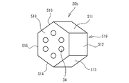
図8は実施例4の基準部20bを示す図である。実施例4においては、面S18またはS19を固定面として基準部20bを筐体12にねじ孔36を用い固定することができる。6個の面S11からS16を基準面として用いることができる。これにより、実施例4によれば1つの基準部20bで12個の基準面を形成することができる。
FIG. 8 is a diagram illustrating the
実施例1および実施例4のように、基準部20または20bは、筐体12に固定される固定面23またはS18を有し、複数の基準面となりうる面21およびS2またはS11からS16は固定面23またはS18と接する面を含むことができる。また、実施例3のように、基準部20aの複数の基準面となりうる面には、固定面(例えばS1)および固定面に対向する面(例えばS4)を含む構成とすることもできる。
As in the first and fourth embodiments, the
実施例1から実施例4は、車両の前方にビームを出射する車両用レーダ装置の例であったが、車両の側方、後方にビームを出射する車両用レーダ装置であってもよい。また、レーダのビームとしてミリ波の例であったが、ビームは電磁波、超音波、赤外線であってもよい。さらに、車両用レーダ装置以外にも、車両の前灯等のライトや車両の画像認識用のカメラ等に実施例1から実施例4の基準部20、20aまたは20bを用いることもできる。
The first to fourth embodiments are examples of a vehicle radar device that emits a beam in front of the vehicle, but may be a vehicle radar device that emits a beam to the side and rear of the vehicle. Moreover, although the example of a millimeter wave was used as a radar beam, the beam may be an electromagnetic wave, an ultrasonic wave, or an infrared ray. Further, in addition to the vehicle radar device, the
本発明の実施例について詳述したが、本発明は係る特定の実施例に限定されるものではなく、特許請求の範囲に記載された本発明の要旨の範囲内において、種々の変形・変更が可能である。 Although the embodiments of the present invention have been described in detail, the present invention is not limited to such specific embodiments, and various modifications and changes can be made within the scope of the gist of the present invention described in the claims. Is possible.
10 車両用レーダ装置
12 筐体
13 背面
13a、13b 面
14 カバー
16 アンテナ
20 基準部
21、22 基準面となりうる面または基準面
23、24 固定面となりうる面または固定面
30 ブラケット
32 軸調整用ボルト
34 ねじ
DESCRIPTION OF
Claims (13)
前記ビーム出射部を搭載する筐体と、
前記筐体に固定され、複数の基準面となりうる面と、複数の固定面となりうる面と、を有する基準部と、
を具備し、前記基準部を前記筐体に固定する際、前記複数の基準面となりうる面のうちいずれの面を基準面とするか及び前記複数の固定面となりうる面のうちいずれの面を固定面とするかにより、前記筐体の前記基準部が固定される面と前記基準面との角度が各々異なることを特徴とする車両用レーダ装置。 A beam emitting section for emitting a beam;
A housing on which the beam emitting unit is mounted;
A reference portion fixed to the housing and having a plurality of reference surfaces and a plurality of fixing surfaces;
And when fixing the reference portion to the housing, which of the plurality of reference surfaces can be used as a reference surface and which of the plurality of fixing surfaces can be used as a reference surface The vehicular radar apparatus, wherein an angle between a surface on which the reference portion of the housing is fixed and the reference surface is different depending on whether the reference surface is a fixed surface.
前記ビームの出射する方向に対応し、基準部の複数の基準面となりうる面のうちいずれかが基準面となり前記基準部の複数の固定面となりうる面のうちいずれかが固定面となるように基準部を前記筐体に固定する工程と、
を有することを特徴とする車両用レーダ装置の製造方法。 A step of measuring a direction in which a beam emitted from a beam emitting unit mounted on the housing is emitted;
Corresponding to the beam exit direction, one of the surfaces that can be a plurality of reference surfaces of the reference portion is a reference surface, and one of the surfaces that can be a plurality of fixed surfaces of the reference portion is a fixed surface. Fixing the reference portion to the housing;
A method for manufacturing a vehicular radar apparatus, comprising:
基準部がビーム出射部を備える筐体に固定される複数の固定面となりうる面と、
を具備し、前記基準部を前記筐体に固定する際、前記複数の基準面となりうる面のうちいずれの面を基準面とするか及び前記複数の固定面となりうる面のうちいずれの面を固定面とするかにより、前記筐体の前記基準部が固定される面と前記基準面との角度が各々異なることを特徴とする基準部。 A surface that can be a plurality of reference surfaces;
A surface that can be a plurality of fixed surfaces that are fixed to a housing in which the reference portion includes a beam emitting portion;
And when fixing the reference portion to the housing, which of the plurality of reference surfaces can be used as a reference surface and which of the plurality of fixing surfaces can be used as a reference surface The reference portion, wherein the angle of the reference surface and the surface to which the reference portion of the housing is fixed differs depending on whether the reference surface is a fixed surface.
Priority Applications (4)
| Application Number | Priority Date | Filing Date | Title |
|---|---|---|---|
| JP2006317887A JP4444265B2 (en) | 2006-11-27 | 2006-11-27 | Vehicular radar apparatus and method for manufacturing the same, reference section, and adjustment method of beam emitting direction |
| EP07121405A EP1925947A1 (en) | 2006-11-27 | 2007-11-23 | In-vehicle radar apparatus and method for manufacturing the same |
| US11/984,985 US7675460B2 (en) | 2006-11-27 | 2007-11-26 | In-vehicle radar apparatus and method for manufacturing the same |
| CNA2007101934545A CN101191834A (en) | 2006-11-27 | 2007-11-27 | In-vehicle radar apparatus and method for manufacturing the same |
Applications Claiming Priority (1)
| Application Number | Priority Date | Filing Date | Title |
|---|---|---|---|
| JP2006317887A JP4444265B2 (en) | 2006-11-27 | 2006-11-27 | Vehicular radar apparatus and method for manufacturing the same, reference section, and adjustment method of beam emitting direction |
Publications (3)
| Publication Number | Publication Date |
|---|---|
| JP2008128995A JP2008128995A (en) | 2008-06-05 |
| JP2008128995A5 JP2008128995A5 (en) | 2008-10-16 |
| JP4444265B2 true JP4444265B2 (en) | 2010-03-31 |
Family
ID=39135153
Family Applications (1)
| Application Number | Title | Priority Date | Filing Date |
|---|---|---|---|
| JP2006317887A Expired - Fee Related JP4444265B2 (en) | 2006-11-27 | 2006-11-27 | Vehicular radar apparatus and method for manufacturing the same, reference section, and adjustment method of beam emitting direction |
Country Status (4)
| Country | Link |
|---|---|
| US (1) | US7675460B2 (en) |
| EP (1) | EP1925947A1 (en) |
| JP (1) | JP4444265B2 (en) |
| CN (1) | CN101191834A (en) |
Cited By (1)
| Publication number | Priority date | Publication date | Assignee | Title |
|---|---|---|---|---|
| JP2008157815A (en) * | 2006-12-25 | 2008-07-10 | Fujitsu Ten Ltd | Radar apparatus for vehicle and its manufacturing method |
Families Citing this family (15)
| Publication number | Priority date | Publication date | Assignee | Title |
|---|---|---|---|---|
| US8405541B2 (en) | 2010-09-01 | 2013-03-26 | Toyota Motor Engineering & Manufacturing North America, Inc. | Multi-range radar system |
| KR101335074B1 (en) * | 2012-03-02 | 2013-12-03 | 주식회사 만도 | Alignment system and method of radar apparatus |
| DE102012204267A1 (en) * | 2012-03-19 | 2013-09-19 | Robert Bosch Gmbh | Sensor holder for a sensor for object detection |
| KR101459910B1 (en) * | 2013-05-28 | 2014-11-07 | 현대자동차주식회사 | Radar apparatus for vehicle |
| US9673517B2 (en) | 2014-04-30 | 2017-06-06 | Honda Motor Co., Ltd. | Vehicle radar cover assembly and method |
| JP6155249B2 (en) * | 2014-12-26 | 2017-06-28 | 株式会社ファルテック | Grill shutter module |
| US9828036B2 (en) | 2015-11-24 | 2017-11-28 | Srg Global Inc. | Active grille shutter system with integrated radar |
| US10534081B2 (en) * | 2016-05-02 | 2020-01-14 | Magna Electronics Inc. | Mounting system for vehicle short range sensors |
| ES2643139B1 (en) * | 2016-05-18 | 2018-09-05 | Illinois Tool Works Inc. | Radar mounting system in vehicles |
| US9956993B1 (en) * | 2017-01-20 | 2018-05-01 | Ford Global Technologies, Llc | Vehicle front impact sensor with impact resistant carriage |
| JP7045249B2 (en) * | 2018-04-19 | 2022-03-31 | 本田技研工業株式会社 | Transport equipment |
| JP7037998B2 (en) * | 2018-04-19 | 2022-03-17 | 本田技研工業株式会社 | Transport equipment |
| JP6973350B2 (en) * | 2018-10-22 | 2021-11-24 | 豊田合成株式会社 | Fixed structure of radio wave radar device |
| US11108147B2 (en) * | 2018-11-13 | 2021-08-31 | Honda Motor Co., Ltd. | Antenna protector |
| JP6952677B2 (en) * | 2018-12-04 | 2021-10-20 | 本田技研工業株式会社 | Detector and vehicle |
Family Cites Families (12)
| Publication number | Priority date | Publication date | Assignee | Title |
|---|---|---|---|---|
| GB0002294D0 (en) * | 2000-02-02 | 2000-03-22 | Jaguar Cars | Automotive radar elevation alignment |
| EP1130416A3 (en) * | 2000-03-02 | 2002-01-30 | Denso Corporation | Forward condition detecting apparatus for vehicles |
| JP3427817B2 (en) * | 2000-03-31 | 2003-07-22 | 株式会社デンソー | Vehicle obstacle recognition method and apparatus, recording medium |
| EP1231480B1 (en) * | 2001-02-08 | 2006-06-21 | Fujitsu Ten Limited | Method and device for aligning radar mount direction, and radar aligned by the method or device |
| JP4698087B2 (en) * | 2001-08-15 | 2011-06-08 | 富士通テン株式会社 | Radar horizontal axis deviation occurrence detection apparatus, axis deviation determination apparatus, and axis deviation correction apparatus |
| JP3838632B2 (en) * | 2002-03-06 | 2006-10-25 | 本田技研工業株式会社 | Method for adjusting detection axis of object detection device |
| JP3676758B2 (en) | 2002-06-04 | 2005-07-27 | 本田技研工業株式会社 | Axis adjusting device for moving body mounting device |
| JP3676757B2 (en) | 2002-06-04 | 2005-07-27 | 本田技研工業株式会社 | Method for adjusting detection axis of object detection device |
| JP3632013B2 (en) * | 2002-06-04 | 2005-03-23 | 本田技研工業株式会社 | Method for adjusting detection axis of object detection device |
| US6714156B1 (en) * | 2002-11-22 | 2004-03-30 | Visteon Global Technologies, Inc. | Method for correcting radar misalignment |
| JP4313089B2 (en) * | 2003-05-23 | 2009-08-12 | 富士通テン株式会社 | Radar apparatus for automobile and its mounting direction adjusting method |
| JP2007125928A (en) * | 2005-11-01 | 2007-05-24 | Mazda Motor Corp | Obstruct detecting device for vehicle |
-
2006
- 2006-11-27 JP JP2006317887A patent/JP4444265B2/en not_active Expired - Fee Related
-
2007
- 2007-11-23 EP EP07121405A patent/EP1925947A1/en not_active Ceased
- 2007-11-26 US US11/984,985 patent/US7675460B2/en not_active Expired - Fee Related
- 2007-11-27 CN CNA2007101934545A patent/CN101191834A/en active Pending
Cited By (1)
| Publication number | Priority date | Publication date | Assignee | Title |
|---|---|---|---|---|
| JP2008157815A (en) * | 2006-12-25 | 2008-07-10 | Fujitsu Ten Ltd | Radar apparatus for vehicle and its manufacturing method |
Also Published As
| Publication number | Publication date |
|---|---|
| US20080122682A1 (en) | 2008-05-29 |
| EP1925947A1 (en) | 2008-05-28 |
| JP2008128995A (en) | 2008-06-05 |
| CN101191834A (en) | 2008-06-04 |
| US7675460B2 (en) | 2010-03-09 |
Similar Documents
| Publication | Publication Date | Title |
|---|---|---|
| JP4444265B2 (en) | Vehicular radar apparatus and method for manufacturing the same, reference section, and adjustment method of beam emitting direction | |
| US10578267B2 (en) | Vehicle lamp light assembly | |
| US10495276B2 (en) | Vehicle light source unit | |
| US20140247390A1 (en) | Automotive camera mounting apparatus | |
| US7661856B2 (en) | Vehicular lamp | |
| JP2018028555A5 (en) | ||
| US9435505B2 (en) | Tilt sensor housing case and vehicle lamp system | |
| US20120187283A1 (en) | Laser radar system and light receiving device | |
| US9448106B2 (en) | Optical sensor | |
| WO2019146647A1 (en) | Lidar device, driving assistance system, and vehicle | |
| EP1480055B1 (en) | Radar apparatus for automobile, attachment direction adjuster and attachment direction adjusting method for radar apparatus | |
| KR20200050612A (en) | Apparatus for zeroing of radar on vehicle and method thereof | |
| US10931932B2 (en) | Supporting housing for stereo camera and circuit board | |
| EP2998643B1 (en) | Lamp for vehicles | |
| US9354139B2 (en) | Headlamp aimer box | |
| JP2010272422A (en) | Vehicular lighting fixture | |
| EP2554432A1 (en) | Sensor mounting structure | |
| KR20200093615A (en) | Car headlamp and method | |
| JP2017114471A (en) | On-vehicle camera and production method thereof | |
| CN112329493A (en) | Aiming indicating device for reading bar code and bar code reading equipment | |
| US20110182071A1 (en) | Beam irradiation device and semiconductor laser device | |
| JP2008157815A (en) | Radar apparatus for vehicle and its manufacturing method | |
| JP7191081B2 (en) | lidar unit with mounting elements for mounting the transmitter module and the receiver module | |
| JP5435213B2 (en) | Vehicle lighting | |
| JP2018077178A (en) | Distance measurement device |
Legal Events
| Date | Code | Title | Description |
|---|---|---|---|
| A521 | Request for written amendment filed |
Free format text: JAPANESE INTERMEDIATE CODE: A523 Effective date: 20080812 |
|
| A621 | Written request for application examination |
Free format text: JAPANESE INTERMEDIATE CODE: A621 Effective date: 20080812 |
|
| A131 | Notification of reasons for refusal |
Free format text: JAPANESE INTERMEDIATE CODE: A131 Effective date: 20081014 |
|
| A521 | Request for written amendment filed |
Free format text: JAPANESE INTERMEDIATE CODE: A523 Effective date: 20081215 |
|
| A131 | Notification of reasons for refusal |
Free format text: JAPANESE INTERMEDIATE CODE: A131 Effective date: 20090623 |
|
| A521 | Request for written amendment filed |
Free format text: JAPANESE INTERMEDIATE CODE: A523 Effective date: 20090811 |
|
| TRDD | Decision of grant or rejection written | ||
| A01 | Written decision to grant a patent or to grant a registration (utility model) |
Free format text: JAPANESE INTERMEDIATE CODE: A01 Effective date: 20100112 |
|
| A01 | Written decision to grant a patent or to grant a registration (utility model) |
Free format text: JAPANESE INTERMEDIATE CODE: A01 |
|
| A61 | First payment of annual fees (during grant procedure) |
Free format text: JAPANESE INTERMEDIATE CODE: A61 Effective date: 20100113 |
|
| R150 | Certificate of patent or registration of utility model |
Free format text: JAPANESE INTERMEDIATE CODE: R150 |
|
| FPAY | Renewal fee payment (event date is renewal date of database) |
Free format text: PAYMENT UNTIL: 20130122 Year of fee payment: 3 |
|
| FPAY | Renewal fee payment (event date is renewal date of database) |
Free format text: PAYMENT UNTIL: 20140122 Year of fee payment: 4 |
|
| FPAY | Renewal fee payment (event date is renewal date of database) |
Free format text: PAYMENT UNTIL: 20150122 Year of fee payment: 5 |
|
| LAPS | Cancellation because of no payment of annual fees |