JP4441897B2 - Manufacturing method of composite magnetic member, manufacturing method of motor using the same, and composite magnetic member and motor using the same - Google Patents
Manufacturing method of composite magnetic member, manufacturing method of motor using the same, and composite magnetic member and motor using the same Download PDFInfo
- Publication number
- JP4441897B2 JP4441897B2 JP2003071552A JP2003071552A JP4441897B2 JP 4441897 B2 JP4441897 B2 JP 4441897B2 JP 2003071552 A JP2003071552 A JP 2003071552A JP 2003071552 A JP2003071552 A JP 2003071552A JP 4441897 B2 JP4441897 B2 JP 4441897B2
- Authority
- JP
- Japan
- Prior art keywords
- magnetic member
- composite magnetic
- manufacturing
- weak magnetic
- ferromagnetic material
- Prior art date
- Legal status (The legal status is an assumption and is not a legal conclusion. Google has not performed a legal analysis and makes no representation as to the accuracy of the status listed.)
- Expired - Fee Related
Links
Images


Description
【0001】
【発明の属する技術分野】
本発明は、単一の素材で強磁性部と弱磁性部を具備する複合磁性部材の製造方法およびこれを用いたモータの製造方法に関するものである。
【0002】
【従来の技術】
従来、本発明者は、単一の素材で強磁性部と弱磁性部を具備する複合磁性部材を提案してきている(例えば、特許文献1参照)。例えば、Fe-Cr−C系を基本組成とする合金は、A3変態点以下での焼鈍処理によりフェライト+炭化物相とすると強磁性を示す。一方、高温での溶体化処理により炭化物を固溶させてオーステナイト相とすると弱磁性化する。
この現象を利用して、フェライト+炭化物相でなる素材を部分的に高温加熱してオーステナイト化すると、強磁性体中に弱磁性部を具備した複合磁性部材を得ることができる。この複合磁性部材は、単一組成でなる部材中に、磁束を通す強磁性部と磁束を通さない(通し難い)弱磁性部を併せ持つことができるので、磁気回路用の部材として適している。また、磁気回路を製造する際にも、強磁性の部材と弱磁性の部材を別々に準備する必要が無く、更に、これらの別部材を接合や溶接によって一体化する必要も無いので、製造工程が簡略化できて便利である。
【0003】
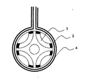
この複合磁性部材の特徴を活かした応用例の一つとして、本発明者らは、モータの回転子を提案している(例えば、特許文献2参照)。磁気抵抗効果を利用したリラクタンスモータの回転子は、図1に示すように、回転子の内部にフラックスバリアと呼ばれる空隙部(1)を形成し、磁束が通り易いd軸方向と磁束が通り難いq軸方向を作製する。
固定子からの界磁により回転子が磁化されると、d軸方向のインダクタンスLdは、q軸方向のインダクタンスLqと比較して大きくなる。リラクタンスモータにおいて高いトルクを得るためには、突極比と呼ばれるLd/Lq値を大きくする必要がある。
【0004】
従来、このリラクタンスモータの回転子には、珪素鋼鈑が使用されてきた(例えば、非特許文献1参照)。但し、珪素鋼鈑を使用した回転子では、回転子外周の連結部(2)に強磁性体が残るため、Ld/Lq値を十分に大きくすることができず、改善が望まれていた。また、Ld/Lq値を大きくするために、連結部(2)の幅を小さくした場合には回転子の機械的強度の低下が問題となっていた。
上述した特許文献2では、回転子に複合磁性部材を用いて連結部(2)を弱磁性化し、回転子の機械的強度を損なうことなくLd/Lq値を大きくすることを提案した。この提案は、リラクタンスモータにおいて、高効率と高強度の特性を両立させたという点で優れた技術である。
【0005】
複合磁性部材を製造する場合には、強磁性体でなる複合磁性部材用素材に対し、部分的な加熱処理を施して強磁性体中に弱磁性部を形成することが必要である。
この部分的な加熱方法として、従来、弱磁性化箇所に局所的にレーザ照射する方法が行われており、上述した特許文献2においても、回転子外周の連結部(2)は、レーザ照射により弱磁性化することを提案している。
レーザ照射は、高密度のエネルギーを局所に集中させる方法であり、弱磁性部を形成する際の有力な手段の一つである。
また、特許文献2には加熱手段として高周波加熱の紹介もあるが、狭い領域の部分加熱にはあまり有効ではないという認識である。
【0006】
【特許文献1】
特開2000−104142号公報
【特許文献2】
特開2001−251822号公報
【非特許文献1】
電気学会論文誌d 116巻6号,1996年
【0007】
【発明が解決しようとする課題】
本発明者らの検討によると、特許文献2で示すようなレーザ照射により弱磁性部を形成する方法では、照射部の少なくとも表面部分、好ましくは弱磁性部全体を溶融凝固させる必要がある。
溶融を伴う熱処理を行うと、溶融後の凝固時に引けが生じる場合や、溶融時に肉盛りが生じる場合があり、弱磁性部において巨視的な割れや変形が生じるという問題がある。また、溶融凝固組織にはデンドライトが形成され、ミクロ偏析等の凝固欠陥が生じるので、回転子の機械的強度の点からも問題となる。更には、レーザ照射では、複合磁性部材用素材の外部より入射するレーザ光のエネルギーによる加熱なので、レーザ照射した側の面と、その反対側の面とでは、形成される弱磁性部の幅が異なるという問題がある。
【0008】
それ故、照射部の幅を厳密に制御することは難しく、弱磁性部において狙い通りの寸法が得られ難いという問題がある。
例えば、モータ回転子のように精密な形状と寸法精度が要求される用途に複合磁性部材を実用化するに当たっては、この弱磁性部における巨視的な割れや変形、寸法精度の悪さが問題となっており、改善が望まれていた。また、レーザ照射では複数の弱磁性部を同時に加熱することが難しいので生産効率が悪く、また設備コストも高いことから、より生産効率が高く、低コストな加熱方法が望まれていた。
【0009】
このような観点から、非溶融の低コストな熱処理方法により弱磁性部を形成する方法として、本発明者の提案による特許文献1あるいは特許文献2には、高周波加熱による熱処理を提案している。しかしながら、単純に高周波コイルを加熱したい箇所に近接させて加熱する方式では、加熱領域が広くなりすぎ、所定の部分のみを加熱することができないという問題があり、採用されてこなかった。
本発明の目的は、複合磁性部材の弱磁性部における巨視的な割れや変形、寸法精度の問題を解決し、更に生産効率が高く、比較的低コストな複合磁性部材の製造方法及びこれを用いたモータの製造方法を提供することである。
【0010】
【課題を解決するための手段】
本発明は従来の高周波コイルを近接させ、その部分を加熱するという高周波コイルのみに着目した従来の加熱方法ではなく、高周波コイルにより発生する電流と、被加熱対象物の形状との関係に着目し、被加熱対象物の形状を調整することで特定の箇所の加熱を可能にしたものである。
即ち本発明は、板状の強磁性素材に空隙が形成され、該空隙と該強磁性素材の外周とによって形成された複数の連結部に弱磁性部が形成された複合磁性部材の製造方法であって、前記強磁性素材の外周を囲んで配置した高周波コイルより高周波を印可して、前記複数の連結部を同時且つ優先的に自己発熱させて、該連結部に非溶融のオーステナイトを主体とする金属組織を有する弱磁性部を形成する複合磁性部材の製造方法である。
【0011】
好ましくは、複合磁性部材用の強磁性素材の外周部に発生する誘起電流の浸透深さP(mm)と、最外周から、弱磁性部を形成する連結部の幅をWr(mm)が、Wr≦Pの関係である複合磁性部材の製造方法である。
P=1.6×{(ρ×105)/(μr×f)}1/2
Wr≦1.6×(ρ×105/f)1/2
ここで、ρ:高周波加熱時の素材の電気抵抗率(μΩ・m)
μr:高周波加熱時の素材の比透磁率
f:高周波加熱時の周波数を[Hz]
【0012】
更に好ましくは、連結部と空隙を同形状に形成した強磁性素材を、連結部が一致するように積層し、次いで前記強磁性素材の外周を囲んで配置した高周波コイルより高周波を印可して、前記連結部を優先的に自己発熱させて、該連結部に非溶融のオーステナイトを主体とする金属組織を有する弱磁性部を形成する複合磁性部材の製造方法である。
更に好ましくは、高周波の印可は、強磁性素材を相対的に移動させながら行う複合磁性部材の製造方法である。
【0013】
本発明に用いる強磁性素材の好ましい化学組成は、質量%でC:0.30〜1.20%、Si:0.10〜2.0%、Mn:0.10〜4.0%、Ni:4.0%以下(0を含む)、Cr:4.0〜20.0%、Al:2.0%以下(0を含む)、残部が実質的にFeの組成でなる複合磁性部材の製造方法である。
【0014】
また本発明は、モータのロータコアとして前記強磁性素材を用い、弱磁性部はロータコア内の磁束遮断域とする、上述の複合磁性部材の製造方法を用いたモータの製造方法である。
【0015】
【発明の実施の形態】
上述したように、本発明の重要な特徴の一つは、弱磁性部の形成方法として高周波加熱を選択し、弱磁性部における巨視的な割れや変形、寸法精度の問題を解決し、更に生産効率を高くすることができる方法にある。
以下、本発明の詳細と規定理由を述べる。
【0016】
まず、弱磁性部を形成するための加熱方法を高周波による加熱とした第一の理由は、前述したように、非溶融の加熱方法により弱磁性部を形成し、弱磁性部における巨視的な割れや変形をなくし、更に寸法精度を高めることができる最良の方法であるからである。
高周波による加熱では被加熱体(本発明では複合磁性部材用の素材)の表面に発生する誘起電流と素材の電気抵抗によりジュール熱が発生する。このジュール熱により素材は自己発熱する。この自己発熱方式は、表面焼入れのように非溶融の熱処理が可能な方法である。
従って、レーザ加工のように複合磁性部材用の強磁性素材を溶融させることなく、強磁性素材の一部に弱磁性部を形成することができる。
【0017】
本発明の製造方法においては、板状の強磁性素材に空隙が形成され、該空隙と該強磁性素材の外周とによって形成された複数の連結部を有する強磁性素材とするように形状の調整をおこなうものである。
上述したように、高周波を印可すると被加熱体には、誘起電流が発生するが、外周側、すなわち高周波を印可される側に、空隙と該強磁性素材の外周とによって連結部が形成される如き形状となっていると、空隙部分は電流が流れることができないため、連結部を流れる電流密度が、他の部分を流れる電流密度よりも高くなる。そのため、連結部のみを高温にすることができる。
【0018】
本発明では例えば図3ように、この高周波加熱コイル(4)と空隙部(3)との間に位置する強磁性素材の部分に連結部(2)を形成し、強磁性素材の外周部より高周波を印可することで、空隙部に隣り合う外周側の複数の連結部(2)に弱磁性部を形成することができるのである。
【0019】
この優先的な自己発熱方式では、複合磁性部材の弱磁性部の寸法精度は、複合磁性部材用素材における弱磁性化箇所の寸法精度と大きな違いはなくなる。すなわち、複合磁性部材用素材の弱磁性化箇所の加工精度を高めれば、複合磁性部材においても寸法精度の高い弱磁性部が得られる。
この方法によれば、複合磁性部材用素材の外部からレーザ照射して弱磁性部を形成する場合と比較して、格段に寸法精度の高い弱磁性部を形成できるし、また、加熱方法を高周波加熱とすると製造コストを安価にできるという利点も有る。
なお、強磁性素材は空隙を形成し易い形状のものを用いるのが良く、プレス打抜きやエッチング等の加工によって空隙部が形成し易い板状の強磁性素材とする。
【0020】
板材を用いると、板材の強磁性素材を積層して高周波加熱による弱磁性部の形成を一度にすることもでき、生産効率を飛躍的に高めることができる。このとき、連結部が形成される如き空隙を同形状として、これらの強磁性素材を連結部が一致するように積層させることが好ましい。
高周波による加熱は、高周波の発生源からの距離の影響を受けるため、効率を考えると、同一外径をもつ板材の強磁性素材を使用して、積層方向から見て同一の形状とすることが望ましい。また、個々の板材の板厚も同じとすることが製造上は有利である。
なお、積層状態での加熱を行う場合には、場所による加熱ムラをなくすために、強磁性材料を相対的に移動させることが好ましい。相対的にとは、材料側でも高周波発生側でも良いという意味である。なお、モータのロータコアとする場合は、円板形状の積層した素材に対して、外周側に高周波コイルを設置し、素材を回転させながら、さらに上下方向に移動させて加熱することがより望ましいものとなる。
【0021】
次に、好ましい範囲として、本発明に適用される複合磁性部材の素材の化学組成を規定した理由を述べる。なお、ここで示す単位は特に示さない限り質量%として示す。
C:0.30〜1.20%
Cは、オーステナイト形成元素として、弱磁性部の形成に有効な元素である。但し、0.30%未満では効果が小さく、逆に1.20%を超える範囲では、素材の加工性が悪くなるので、0.30〜1.20%に規定した。
Si:0.10〜2.0%
Siは、素材の軟磁気特性を向上させる効果がある元素である。但し、0.10%未満では効果が小さく、逆に2.0%を超える範囲では、素材の加工性が悪くなるので、0.10〜2.0%に規定した。
【0022】
Mn:0.10〜4.0%
Mnは、オーステナイト形成元素として、弱磁性部の形成に有効な元素である。但し、0.10%未満では効果が小さく、逆に4.0%を超える範囲では、素材の加工性が悪くなるので、0.10〜4.0%に規定した。
Ni:4.0%以下(0を含む)
Niも、オーステナイト形成元素として、弱磁性部の形成に有効な元素であり、特定量の範囲で添加が可能である。但し、素材コストを上げるので、コストを抑えたい場合には無添加でも構わない。Niを添加する場合、4.0%を超えると素材の加工性が著しく悪くなるので、Niの範囲は、4.0%以下(0を含む)とした。
【0023】
Cr:4.0〜20.0%
Crは、素材の耐食性を高め、更に電気抵抗率を高める効果がある。また、弱磁性部の残留オーステナイトを安定化させる効果もある。但し、4.0%未満では、それぞれの効果が小さく、また20.0%を超える範囲では、素材の飽和磁化量が著しく低下するとともに、加工性が悪くなるので、4.0〜20.0%に規定した。
Al:2.0%以下(0を含む)
Alは、Siと同様に、素材の軟磁気特性を向上させる効果がある元素であり、特定量の範囲で添加が可能である。但し、介在物を形成して素材の加工性を悪くするので、無添加でも良い。また、2.0%を超える範囲では、素材の加工性が悪くなるので、2.0%以下(0を含む)と規定した。
なお、複合磁性部材用素材の組成は、残部が実質的にFeでなることとするが、不可避不純物としてのP、S、O、Nは当然含まれる。これらの元素は、素材の磁気特性や加工性に特に影響しない範囲として、各々、0.1%以下の範囲で含有しても良い。
【0024】
上述した組成の材料は、(フェライト+炭化物)を主体とする強磁性の組織に容易に調整できるものである。そして、加熱により弱磁性のオーステナイトを形成できる。つまり、フェライト相は強磁性体であるが、加熱により炭化物を固溶させると弱磁性のオーステナイト相が安定化するため複合磁性部材を形成するのに適するのである。
【0025】
本発明の製造方法を適用した場合、寸法精度の高い弱磁性部を形成できるし、製造コストを安価にできるという利点があり、モータの製造方法として最適である。
モータのロータコアとして本発明を適用する場合は、モータのロータコアとして前記強磁性素材を用い、弱磁性部はロータコア内の磁束遮断域とすることになる。
いわゆるリラクタンス型のモータのロータコアでは、本発明の空隙をフラックスバリアとして適用することで、空隙と弱磁性部でロータコアの外周までフラックスバリアを連続させることができるようになる。これにより、リラクタンスモータの性能の評価値である突極比(Ld/Lq値)を大きくすることが可能となる。
また、例えば内部磁石型のモータのロータコアとして適用する場合は、空隙は磁石の設置空間やフラックスバリアとすることができ、空隙とそれに続く弱磁性部でロータコアの外周までフラックスバリアを連続させることができるようになる。
【0026】
以下、より好ましい形態について説明する。
高周波による加熱時の条件を以下のように設定すると特に望ましい。
例えば、最外周からの弱磁性化箇所の幅Wrとした場合、複合磁性部材用の強磁性素材の外周部に発生する誘起電流の浸透深さP(mm)は、高周波加熱時の素材の電気抵抗率をρ(μΩ・m)、高周波加熱時の素材の比透磁率をμr、高周波加熱時の周波数をf[Hz]とすると、下記の式により表される。
P=1.6×{(ρ×105)/(μr×f)}1 / 2
【0027】
本発明に対して上述の好ましい組成範囲を有する強磁性素材に弱磁性部を形成するためには、少なくとも1000℃以上の加熱することが必要である。この温度は、強磁性素材のCurie点(約700℃付近)より高いので、加熱時の弱磁性化箇所の比透磁率μrは、μr=1である。従って、上記の式は、下記式のように書き換えられる。
P=1.6×(ρ×105/f)1 / 2
【0028】
最外周から、弱磁性部を形成する連結部の幅をWr(mm)を、上記の書き換えた式で表される浸透深さPよりも小さくしておけば、弱磁性部を形成する連結部を流れる電流密度は、外周部の弱磁性化しない箇所を流れる電流密度より高くなる。従って、弱磁性化したい連結部のみが、ジュール熱により優先的に自己発熱する。
また、外周部の弱磁性化しない箇所に発生したジュール熱は、熱伝導により複合磁性部材用素材の内部に拡散するのに対し、弱磁性部を形成する連結部に発生したジュール熱は拡散し難い。その理由は、空隙が存在するからである。この点からも弱磁性部を形成する連結部の温度は高温となり易い。
【0029】
以上の理由から、最外周から、弱磁性部を形成する連結部の幅Wr(mm)は、浸透深さPよりも小さいことが望ましいが、同じ幅であっても良い。それ故、最外周から、弱磁性部を形成する連結部の幅をWr(mm)は、下記式の範囲を満足させると良い。
Wr≦1.6×(ρ×105/f)1/2
なお、好ましい周波数fの範囲は、3,000(Hz)から1,000,000(Hz)の範囲である。
【0030】
次に本発明においての複合磁性部材について説明する。
本発明においては、上述した製造方法によって製造できるものであって、内部より加熱変態させた弱磁性部を形成しているという特徴をもつ。外部から局所的にエネルギーを与えるレーザや、高周波コイルを近接させ近接部表面のみを発熱させる局所的な加熱ではなく、高周波による誘起電流と、空隙に起因する抵抗と、空隙による熱の拡散の阻害によって、内部より加熱変態できたものである。
そして、上述したように、加熱変態した連結部を非溶融のオーステナイトを主体とする金属組織とすることで、寸法精度の高い複合磁性材料となるものである。
【0031】
なお、本発明において、加熱変態したオーステナイトを主体とする組織において、弱磁性部をエックス線回折により分析した際、検出されるすべての相のピーク強度の総和の内、70%以上をオーステナイト相のピークが占める組織とすることが望ましい。オーステナイト量が、この範囲にまで多くなっていれば、弱磁性部としてより有効に作用する。なお、オーステナイトを主体とする組織において、組織中に若干量の未固溶炭化物や介在物、マルテンサイト等が含まれていてもよい。
なお、本発明の複合磁性部材やモータにおいて、空隙は、空隙のままであっても良いが、強度向上のためなどに樹脂などを充填して用いても良い。また、上述したように磁石を内装しても良いものである。
【0032】
本発明の複合磁性部材では、上述した加熱方法を採用するため、外部からの局所的な加熱方法とは異なり、連結部における弱磁性部の外周側の幅と内周側の幅をほぼ均等とすることもできる。
従来のレーザ照射では、必然的に照射した側の面が広く、その反対側の面は狭くなってしまうのとは異なる効果である。具体的には、弱磁性部の外周側の幅Wθ 1と内周側の幅Wθ 2の比Wθ1/Wθ2を0.9〜1.1とすることもできる。
【0033】
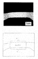
なお、従来方法で得られる複合磁性部材と本発明の方法で得られる複合磁性部材の弱磁性部とを比較すると、図5(本発明方法適用)及び図6(従来方法適用)となる。図5及び図6は弱磁性部を形成した複合磁性部材の上面からの顕微鏡写真であり、平面研磨後に王水によるエッチングを行ったものであり、白く見える場所が弱磁性部である。その両側には熱影響部(薄い灰色に見える)が存在し、強磁性部(灰色に見える)となっている。
図5及び図6に示す弱磁性部の形状から、本発明の弱磁性部は割れや変形もないことが分かる。
【0034】
この本発明の複合磁性部材は上述したように、弱磁性部の割れや変形が防止できることから、精密な形状と寸法精度が要求される用途であるモータの回転子に好適である。モータの回転子の一例を示すと、例えば上述のフラックスバリアと呼ばれる空隙部を有したモータでは、例えば図1に示すように円盤状の板材に空隙部(1)が形成され、連結部(2)に弱磁性部が形成された形態となる。このモータの回転子は、高い突極比を得ることができるので、リラクタンスモータとして活用することができるし、また、空隙部(1)の中に永久磁石を埋め込めば、内部磁石型のモータとしても適用できる。
【0035】
本発明の複合磁性部材を用いた回転子の強磁性部の飽和磁化量は1.2T以上とすることができ、また弱磁性部の飽和磁化量は0.5T以下とすることができる。強磁性部と弱磁性部の飽和磁化量がこの範囲内であれば、複合磁性部材が、モータ回転子となった際の突極比(Ld/Lq値)を十分に大きくすることができるので、モータ回転子に要求された磁気特性を十分に満足できるものである。なお、化学組成を本発明で規定する好ましい範囲に調整することで、強磁性部の飽和磁化量は1.4T以上とすることができ、また弱磁性部の飽和磁化量は0.3T以下とすることも可能である。
【0036】
【実施例】
本実施例で複合磁性部材用の強磁性素材として用いた強磁性素材の化学組成(質量%)を表1に示す。エックス線回折により、この素材は(フェライト+M23C6型炭化物)相でなることを確認した。なお、強磁性素材は熱間圧延、冷間圧延、焼鈍を繰返して最終的に冷間圧延により0.35mmの厚みの板材とした。
また、振動試料型磁束計により、1T(テスラ)の外部磁場を印加した際の飽和磁化量は1.51Tであり強磁性を示していた。
【0037】
【表1】

板厚0.35mmの素材にプレス打ち抜き加工を行って、図2に示す形状の直径80mmの強磁性素材とした。弱磁性化箇所は、図2の複合磁性部材用素材の外周部に存在する8ヶ所の連結部(2)である。
なお、弱磁性化箇所の連結部(2)と隣り合う箇所には、電気絶縁体領域(3)として、プレス打ち抜きで空隙部も形成した。図2の強磁性素材において、最外周からの弱磁性化箇所の幅Wr(mm)は、1.2mmである。
【0039】
図2の複合磁性部材用の強磁性素材の1枚を、図3に示すように高周波加熱コイル(4)内に設置し、強磁性素材の外周を囲んで配置した高周波コイルより周波数f=25,000(Hz)の条件で高周波を印可し、加熱を行った。
高周波加熱により、8ヶ所の連結部(2)が同時に自己発熱を起こし、赤くなる様子が観察された。放射温度計により発熱した連結部(2)の温度を測温したところ、約1200℃に昇温していた。
表1の複合磁性部材用素材の1200℃での電気抵抗率ρは、1.2(μΩ・m)である。従って、この条件下で複合磁性部材用素材の外周部に生じている誘起電流の浸透深さP(mm)は、上記式より、
P=1.6×(ρ×105/f)1/2=3.5(mm)
となる。
本実施例では、最外周からの弱磁性化箇所の幅Wr(mm)を1.2mmとしており、複合磁性部材用素材が関係式 Wr≦1.6×(ρ×105/f)1/2を満たすように形成されている。それ故、上述した連結部(2)のみの優先的な自己発熱が可能であった。
【0040】
次に、図2に示す複合磁性部材用の強磁性素材を100枚積層した状態で弱磁性部を形成するための高周波加熱を行った。
この時の複合磁性材の強磁性素材は、予め同形状として連結部が一致するように積層した状態とした。
場所による加熱ムラをなくすため、積層した素材を500rpmの速度で回転させながら、上下方向に4mm/Sの速度で移動させた。加熱後の外観を確認したところ、1枚の素材を加熱した時と同様に、8ヶ所の連結部(2)のみが、自己発熱していた。
【0041】
上述の方法により、部分的に自己発熱した100枚のうちの1枚を取り出し、弱磁性化箇所の磁性測定用試料として、連結部(2)(=自己発熱部)の内の1ヶ所を切出した。また、外周部の弱磁性化しない箇所として、連結部(2)と隣り合う外周部の強磁性部からも2mm×3mm程度の磁性測定用試料を切り出した。振動試料型磁束計を用いて、1T(テスラ)の外部磁場を印加した際の各箇所の飽和磁化量を測定したところ、連結部(2)の飽和磁化量は0.20Tであり、連結部(2)と隣り合う外周部の強磁性部の飽和磁化量は1.51Tであった。
【0042】
この結果より、連結部(2)は弱磁性部になること、及び外周部の連結部以外の強磁性部においては、複合磁性部材用素材の強磁性の特性が保たれていることが分かる。
上述の製造方法により、本実施例の複合磁性部材用素材は、一体の部材中に強磁性部と弱磁性部を併せ持つ複合磁性部材となった。強磁性部と弱磁性部のそれぞれの飽和磁化量が上記のレベルであれば、例えば、モータ回転子としても、十分に使用できるものとなっていた。
【0043】
上述の複合磁性部材の弱磁性部を微小部エックス線回折により分析した結果を図4に示す。図4より、オーステナイト相(γ)とマルテンサイト相(α’)が検出されている。また、検出されるすべてのピークに対するオーステナイト相のピークの比率は80.7%であり、オーステナイトを主体とする組織でなることが分かる。また、弱磁性部とその周辺部の組織を光学顕微鏡により観察した結果を図5に示す。図5で白く見える部分が弱磁性部であり、弱磁性部の拡大組織を顕微鏡観察することにより、弱磁性部はデンドライトの無い非溶融組織であることを確認した。
また、強磁性部の金属組織も確認したところ、強磁性素材と同様の(フェライト+M23C6型炭化物)相となっていた。
また、図5に示すように弱磁性部には巨視的な割れや変形は無いことが分かる。更に、弱磁性部の外周側の幅Wθ1は3.44mmであり、内周側の幅Wθ2は3.36mmであるので、両者の比Wθ1/Wθ2は1.02となっていた。
【0044】
一方、比較例の製造方法として、CO2レーザを用いた溶融凝固処理により複合磁性部材を作製した。複合磁性部材用素材の化学組成は、表1と同じである。複合磁性部材用素材の形状も図2の形状と同様とし、100枚の素材を積層して外周部に位置する連結部を弱磁性化箇所した。
CO2レーザの入熱量は、70(J/mm2)であった。CO2レーザを用いた製造方法では、積層した素材の側面からレーザビームを照射し、連結部全体を溶融凝固させた。
溶融凝固後の連結部の飽和磁化量は0.18Tであり、弱磁性部は形成された。
【0045】
比較例の製造方法により作製した複合磁性部材の弱磁性部と周辺部の組織を図6に示す。図6で白く見える部分が弱磁性部である。弱磁性部の拡大組織を顕微鏡観察したところ、デンドライトが観察された。
図6より、この方法により作製した複合磁性部材では、凝固時の引けや溶融時の肉盛りが生じており、結果として弱磁性部に巨視的な割れや変形が生じている。また、弱磁性部の外周側の幅Wθ1は1.83mmであり、内周側の幅Wθ2は1.59mmであるので、両者の比Wθ1/Wθ2は1.15となっており、本発明方法を適用した複合磁性部材と比較し、弱磁性部の外側と内側との幅にバラツキが大きいものとなっていた。
以上の実施例から、本発明の高周波加熱による製造方法では、非溶融の加熱によって弱磁性部を形成することができ、ひいては弱磁性部における巨視的な割れや変形が無く、寸法精度も高い複合磁性部材を製造できることが分かる。一方、比較例のレーザを用いた製造方法では、溶融を伴う熱処理であるため、弱磁性部における巨視的な割れや変形が発生し、寸法精度も劣っている。
【0046】
本発明の複合磁性部材を図1に示す回転子とした。
回転子は、リラクタンスモータ用であり、空隙はリラクタンスモータ用ロータコアのフラックスバリアとし、弱磁性部の連結部は突極部域とした。
この回転子は、弱磁性部において巨視的な割れや変形が無く、狙い通りの寸法精度が得られているので、複合磁性部材を用いた回転子の特徴である高い突極比(Ld/Lq値)と高い強度特性を最大限に発揮することができる。それ故、この回転子を有するモータは、高効率モータとして実用に供することが、十分可能である。
【0047】
【発明の効果】
本発明によれば、複合磁性部材の弱磁性部における巨視的な割れや変形、寸法精度の悪さの問題を飛躍的に改善した製造方法および複合磁性部材および該複合磁性部材を用いてなるモータを提供することができる。本発明は、複合磁性部材を、モータ回転子のような精密な形状と寸法精度が要求される用途に実用化するに当たって欠くことのできない技術となる。
【図面の簡単な説明】
【図1】複合磁性部材を用いてなるモータ回転子を示す模式図である。
【図2】本発明の製造方法における複合磁性部材用素材を示す模式図である。
【図3】本発明の製造方法を示す模式図である。
【図4】本発明の複合磁性部材の弱磁性部のエックス線回折図形である。
【図5】本発明の複合磁性部材の弱磁性部と周辺部の光学顕微鏡観察組織である。
【図6】比較例の複合磁性部材の弱磁性部と周辺部の光学顕微鏡観察組織である。
【符号の説明】
1.空隙部、2.連結部、3.電気絶縁体領域、4.高周波加熱コイル[0001]
BACKGROUND OF THE INVENTION
The present invention relates to a manufacturing method and how the motor using this composite magnetic member having a ferromagnetic portion and a weak magnetic portion in a single material.
[0002]
[Prior art]
Conventionally, the inventor has proposed a composite magnetic member including a ferromagnetic portion and a weak magnetic portion with a single material (see, for example, Patent Document 1). For example, an alloy having a basic composition of Fe-Cr-C system shows the ferromagnetic and ferrite + carbide phase by annealing at below A 3 transformation point. On the other hand, when a carbide is dissolved in a solution treatment at a high temperature to form an austenite phase, it becomes weak magnetized.
Utilizing this phenomenon, when a material composed of a ferrite + carbide phase is partially heated to austenite to obtain a composite magnetic member having a weak magnetic portion in a ferromagnetic material. This composite magnetic member is suitable as a member for a magnetic circuit, because a member having a single composition can have both a ferromagnetic portion through which magnetic flux passes and a weak magnetic portion through which magnetic flux does not pass (which is difficult to pass). Also, when manufacturing a magnetic circuit, there is no need to prepare a ferromagnetic member and a weak magnetic member separately, and further, there is no need to integrate these separate members by joining or welding. Can be simplified.
[0003]
As one application example utilizing the characteristics of the composite magnetic member, the present inventors have proposed a rotor of a motor (see, for example, Patent Document 2). As shown in FIG. 1, the rotor of the reluctance motor using the magnetoresistive effect forms a gap (1) called a flux barrier inside the rotor, and the magnetic flux easily passes through the d-axis direction and the magnetic flux is difficult to pass. The q-axis direction is produced.
When the rotor is magnetized by the field from the stator, the inductance Ld in the d-axis direction becomes larger than the inductance Lq in the q-axis direction. In order to obtain high torque in the reluctance motor, it is necessary to increase the Ld / Lq value called salient pole ratio.
[0004]
Conventionally, a silicon steel plate has been used for the rotor of the reluctance motor (see, for example, Non-Patent Document 1). However, in a rotor using a silicon steel plate, since the ferromagnetic material remains in the connecting portion (2) on the outer periphery of the rotor, the Ld / Lq value cannot be sufficiently increased, and improvement has been desired. Further, when the width of the connecting portion (2) is reduced in order to increase the Ld / Lq value, there has been a problem of a decrease in the mechanical strength of the rotor.
In
[0005]
When manufacturing a composite magnetic member, it is necessary to form a weak magnetic part in the ferromagnetic material by subjecting the material for the composite magnetic member made of a ferromagnetic material to partial heat treatment.
Conventionally, as this partial heating method, a method of locally irradiating a weakly magnetized portion with a laser has been performed. Also in
Laser irradiation is a method of concentrating high-density energy locally, and is one of the effective means for forming a weak magnetic part.
[0006]
[Patent Document 1]
JP 2000-104142 A [Patent Document 2]
JP 2001-251822 A [Non-Patent Document 1]
IEEJ Transactions Volume 116, No.6, 1996 [0007]
[Problems to be solved by the invention]
According to the study by the present inventors, in the method of forming the weak magnetic part by laser irradiation as shown in
When heat treatment with melting is performed, there is a case where shrinkage occurs during solidification after melting, or a build-up occurs during melting, and there is a problem that macroscopic cracks and deformation occur in the weak magnetic part. In addition, dendrites are formed in the melt-solidified structure and solidification defects such as microsegregation occur, which is also a problem from the viewpoint of the mechanical strength of the rotor. Furthermore, in laser irradiation, since heating is performed by the energy of laser light incident from the outside of the composite magnetic member material, the width of the weak magnetic portion formed on the surface irradiated with the laser and the surface on the opposite side is small. There is a problem of being different.
[0008]
Therefore, it is difficult to strictly control the width of the irradiation part, and there is a problem that it is difficult to obtain a target dimension in the weak magnetic part.
For example, when a composite magnetic member is put to practical use in applications where precise shape and dimensional accuracy are required, such as a motor rotor, macroscopic cracks and deformation in this weak magnetic part, and poor dimensional accuracy become problems. The improvement was desired. Further, since it is difficult to simultaneously heat a plurality of weak magnetic parts by laser irradiation, the production efficiency is low and the equipment cost is high. Therefore, a heating method with higher production efficiency and lower cost has been desired.
[0009]
From this point of view,
An object of the present invention is to solve the problems of macroscopic cracks and deformations in a weak magnetic part of a composite magnetic member, dimensional accuracy, and to produce a composite magnetic member with high production efficiency and relatively low cost. it is to provide a manufacturing how of the motor had.
[0010]
[Means for Solving the Problems]
The present invention focuses on the relationship between the current generated by the high-frequency coil and the shape of the object to be heated, rather than the conventional heating method focusing only on the high-frequency coil in which a conventional high-frequency coil is brought close to and heated at that portion. The specific part can be heated by adjusting the shape of the object to be heated.
That is, the present invention is a method of manufacturing a composite magnetic member in which a gap is formed in a plate-like ferromagnetic material, and weak magnetic portions are formed at a plurality of connecting portions formed by the gap and the outer periphery of the ferromagnetic material. And applying a high frequency from a high-frequency coil arranged around the outer periphery of the ferromagnetic material to cause the plurality of connecting portions to self-heat preferentially at the same time , mainly comprising unmelted austenite in the connecting portions. This is a method of manufacturing a composite magnetic member that forms a weak magnetic part having a metallic structure.
[0011]
Preferably, the penetration depth P (mm) of the induced current generated in the outer peripheral portion of the ferromagnetic material for the composite magnetic member and the width of the connecting portion forming the weak magnetic portion from the outermost periphery is Wr (mm). This is a method for manufacturing a composite magnetic member having a relationship of Wr ≦ P.
P = 1.6 × {(ρ × 10 5 ) / (μr × f)} 1/2
Wr ≦ 1.6 × (ρ × 10 5 / f) 1/2
Where ρ is the electrical resistivity of the material during high frequency heating (μΩ · m)
μr: Relative permeability of material during high frequency heating f: Frequency during high frequency heating [Hz]
[0012]
More preferably, the ferromagnetic material in which the connecting portion and the gap are formed in the same shape is laminated so that the connecting portion is coincident, and then a high frequency is applied from a high frequency coil arranged so as to surround the outer periphery of the ferromagnetic material, This is a method for manufacturing a composite magnetic member in which a weak magnetic part having a metal structure mainly composed of unmelted austenite is formed in the connecting part by preferentially heating the connecting part.
More preferably, high-frequency application is a method of manufacturing a composite magnetic member that is performed while relatively moving a ferromagnetic material.
[0013]
The preferable chemical composition of the ferromagnetic material used in the present invention is C: 0.30 to 1.20% in mass%, Si: 0.10 to 2.0%, Mn: 0.10 to 4.0%, Ni : 4.0% or less (including 0), Cr: 4.0-20.0%, Al: (including 0) 2.0% or less, the composite magnetic member and the balance of the composition of substantially Fe It is a manufacturing method .
[0014]
The present invention uses the ferromagnetic material as the rotor core of the motors, the weak magnetic portion and the magnetic flux blocking region in the rotor core, a motor manufacturing method using the manufacturing method of a composite magnetic member described above.
[0015]
DETAILED DESCRIPTION OF THE INVENTION
As described above, one of the important features of the present invention is that high-frequency heating is selected as a method for forming the weak magnetic part, which solves the problems of macroscopic cracks and deformation and dimensional accuracy in the weak magnetic part, and further produces. There is a method that can increase the efficiency.
The details of the present invention and the reasons for its definition will be described below.
[0016]
First, the first reason why the heating method for forming the weak magnetic part is high frequency heating is that, as described above, the weak magnetic part is formed by the non-melting heating method, and macroscopic cracks in the weak magnetic part are formed. This is because this is the best method that can eliminate the deformation and further improve the dimensional accuracy.
In heating by high frequency, Joule heat is generated by an induced current generated on the surface of a heated object (a material for a composite magnetic member in the present invention) and an electric resistance of the material. The Joule heat causes the material to self-heat. This self-heating method is a method capable of non-melting heat treatment such as surface quenching.
Therefore, the weak magnetic part can be formed in a part of the ferromagnetic material without melting the ferromagnetic material for the composite magnetic member as in laser processing.
[0017]
In the manufacturing method of the present invention, the shape is adjusted so as to obtain a ferromagnetic material having a plurality of connecting portions formed by a gap formed in the plate-like ferromagnetic material and the outer periphery of the gap and the ferromagnetic material. It is to do.
As described above, when a high frequency is applied, an induced current is generated in the object to be heated. However, on the outer peripheral side, that is, the side where the high frequency is applied, a coupling portion is formed by the gap and the outer periphery of the ferromagnetic material. In such a shape, since current cannot flow through the gap portion, the current density flowing through the connecting portion is higher than the current density flowing through other portions. Therefore, only the connecting part can be heated.
[0018]
In the present invention, for example, as shown in FIG. 3 , a connecting portion (2) is formed in the portion of the ferromagnetic material located between the high-frequency heating coil (4) and the gap portion (3), and the outer peripheral portion of the ferromagnetic material is used. by applying a high frequency, it is possible to form a weak magnetic portion in a plurality of connecting portions of the outer peripheral side adjacent to the air gap (2).
[0019]
In this preferential self-heating method, the dimensional accuracy of the weak magnetic portion of the composite magnetic member is not significantly different from the dimensional accuracy of the weakly magnetized portion in the composite magnetic member material. That is, if the processing accuracy of the weakened portion of the composite magnetic member material is increased, a weak magnetic portion with high dimensional accuracy can be obtained even in the composite magnetic member.
According to this method, it is possible to form a weak magnetic part with a remarkably high dimensional accuracy as compared with the case where a weak magnetic part is formed by laser irradiation from the outside of the material for the composite magnetic member. Heating also has the advantage that manufacturing costs can be reduced.
Note that the ferromagnetic material may to use one of the easy shape to form a void, shall be the likely plate-shaped ferromagnetic material gap portion is formed by machining such as press-punching or etching.
[0020]
When the plate material is used, the ferromagnetic material of the plate material can be laminated to form the weak magnetic part by high frequency heating at a time, and the production efficiency can be dramatically increased. At this time, it is preferable that the gaps in which the connecting portions are formed have the same shape, and these ferromagnetic materials are laminated so that the connecting portions coincide.
Since heating by high frequency is affected by the distance from the source of high frequency, considering the efficiency, it is possible to use a ferromagnetic material of a plate material having the same outer diameter and make it the same shape when viewed from the stacking direction. desirable. In addition, it is advantageous in manufacturing that the plate thickness of each plate is the same.
In addition, when heating in a laminated state, it is preferable to move the ferromagnetic material relatively in order to eliminate heating unevenness depending on the location. Relative means that the material side or the high frequency generation side may be used. In the case of a rotor core for a motor, it is more desirable to install a high frequency coil on the outer peripheral side of the disk-shaped laminated material and heat it by moving it further in the vertical direction while rotating the material. It becomes.
[0021]
Next, the reason why the chemical composition of the material of the composite magnetic member applied to the present invention is defined as a preferable range will be described. The units shown here are expressed as mass% unless otherwise specified.
C: 0.30 to 1.20%
C is an element effective for forming a weak magnetic part as an austenite forming element. However, if the content is less than 0.30%, the effect is small. Conversely, if the content exceeds 1.20%, the workability of the material is deteriorated, so the content is specified to be 0.30 to 1.20%.
Si: 0.10 to 2.0%
Si is an element that has the effect of improving the soft magnetic properties of the material. However, if the content is less than 0.10%, the effect is small. On the other hand, if the content exceeds 2.0%, the workability of the material is deteriorated.
[0022]
Mn: 0.10 to 4.0%
Mn is an effective element for forming a weak magnetic part as an austenite forming element. However, if the content is less than 0.10%, the effect is small. On the other hand, if the content exceeds 4.0%, the workability of the material deteriorates. Therefore, the content is specified to be 0.10 to 4.0%.
Ni: 4.0% or less (including 0)
Ni is also an element effective for forming a weak magnetic part as an austenite-forming element, and can be added in a specific amount range. However, since the material cost is increased, no additive may be added if it is desired to reduce the cost. In the case of adding Ni, if it exceeds 4.0%, the workability of the material is remarkably deteriorated, so the range of Ni is set to 4.0% or less (including 0).
[0023]
Cr: 4.0 to 20.0%
Cr has the effect of increasing the corrosion resistance of the material and further increasing the electrical resistivity. In addition, there is an effect of stabilizing the retained austenite of the weak magnetic part. However, if the content is less than 4.0%, the respective effects are small. If the content exceeds 20.0%, the saturation magnetization of the material is remarkably reduced and the workability is deteriorated. %.
Al: 2.0% or less (including 0)
Al, like Si, is an element that has the effect of improving the soft magnetic properties of the material, and can be added in a specific amount range. However, since inclusions are formed and workability of the material is deteriorated, no addition may be performed. In addition, in the range exceeding 2.0%, the workability of the material is deteriorated, so it is defined as 2.0% or less (including 0).
The composition of the composite magnetic member material is essentially composed of Fe, but naturally includes P, S, O, and N as inevitable impurities. Each of these elements may be contained in a range of 0.1% or less as a range that does not particularly affect the magnetic properties and workability of the material.
[0024]
The material having the above composition can be easily adjusted to a ferromagnetic structure mainly composed of (ferrite + carbide). And weak magnetic austenite can be formed by heating. In other words, the ferrite phase is a ferromagnetic material, but when the carbide is dissolved in the solution by heating, the weak magnetic austenite phase is stabilized, which is suitable for forming a composite magnetic member.
[0025]
When the manufacturing method of the present invention is applied, a weak magnetic part with high dimensional accuracy can be formed and the manufacturing cost can be reduced, which is optimal as a motor manufacturing method.
When the present invention is applied as a rotor core of a motor, the ferromagnetic material is used as the rotor core of the motor, and the weak magnetic part is a magnetic flux blocking area in the rotor core.
In the rotor core of a so-called reluctance type motor, by applying the gap of the present invention as a flux barrier, the flux barrier can be continued to the outer periphery of the rotor core by the gap and the weak magnetic part. As a result, the salient pole ratio (Ld / Lq value), which is an evaluation value of the performance of the reluctance motor, can be increased.
For example, when applied as a rotor core of an internal magnet type motor, the air gap can be a magnet installation space or a flux barrier, and the flux barrier can be continued to the outer periphery of the rotor core by the air gap and the weak magnetic part that follows. become able to.
[0026]
Hereinafter, more preferable embodiments will be described.
It is particularly desirable to set the conditions at the time of heating by high frequency as follows.
For example, when the width Wr of the weakly magnetized portion from the outermost periphery is set, the penetration depth P (mm) of the induced current generated in the outer peripheral portion of the ferromagnetic material for the composite magnetic member is the electric power of the material during high-frequency heating. When the resistivity is ρ (μΩ · m), the relative permeability of the material during high-frequency heating is μr, and the frequency during high-frequency heating is f [Hz], it is expressed by the following equation.
P = 1.6 × {(ρ × 10 5) / (μr × f)} 1/2
[0027]
In order to form the weak magnetic part in the ferromagnetic material having the above-described preferable composition range with respect to the present invention, it is necessary to heat at least 1000 ° C. or more. Since this temperature is higher than the Curie point (around 700 ° C.) of the ferromagnetic material, the relative permeability μr of the weakened portion at the time of heating is μr = 1. Therefore, the above equation can be rewritten as the following equation.
P = 1.6 × (ρ × 10 5 / f) 1/2
[0028]
If the width of the connecting part forming the weak magnetic part is made smaller than the penetration depth P expressed by the above rewritten formula from the outermost periphery , the connecting part forming the weak magnetic part Is higher than the current density that flows through a portion of the outer peripheral portion that is not weakly magnetized. Therefore, only the connecting portion that is desired to be weakly magnetized preferentially generates heat due to Joule heat.
In addition, Joule heat generated in the outer peripheral portion where it is not weakly magnetized diffuses inside the composite magnetic member material due to heat conduction, whereas Joule heat generated in the connecting portion forming the weak magnetic portion diffuses. hard. The reason is that there are voids. Also from this point, the temperature of the connecting portion forming the weak magnetic portion tends to be high.
[0029]
For the above reasons, the width Wr (mm) of the connecting portion forming the weak magnetic portion is desirably smaller than the penetration depth P from the outermost periphery , but may be the same width. Therefore, from the outermost periphery, the width of the connecting portion forming the weak magnetic portion Wr (mm) is may satisfy the range of the following formula.
Wr ≦ 1.6 × (ρ × 10 5 / f) 1/2
In addition, the range of the preferable frequency f is the range of 3,000 (Hz) to 1,000,000 (Hz).
[0030]
Next, the composite magnetic member in the present invention will be described.
The present invention can be manufactured by the above-described manufacturing method, and has a feature that a weak magnetic portion is formed by heat transformation from the inside. Rather than a local laser that gives energy locally from the outside, or a local heating that heats only the surface of the proximity part by bringing a high-frequency coil close to it, high-frequency induced current, resistance due to the air gap, and inhibition of heat diffusion due to the air gap Thus, the heat transformation can be performed from the inside.
And as above-mentioned, it becomes a composite magnetic material with high dimensional accuracy by making the connection part which carried out the heat transformation into the metal structure which has a non-melting austenite as a main body.
[0031]
In the present invention, in the structure mainly composed of heat-transformed austenite, when the weak magnetic part is analyzed by X-ray diffraction, 70% or more of the sum of the peak intensities of all the phases detected is 70% of the peak of the austenite phase. It is desirable to have an organization that occupies. If the amount of austenite is increased to this range, it acts more effectively as a weak magnetic part. In the structure mainly composed of austenite, the structure may contain some amount of insoluble carbides, inclusions, martensite, and the like.
In the composite magnetic member and motor of the present invention, the gap may be left as it is, but may be filled with a resin or the like for improving the strength. Further, as described above, a magnet may be incorporated.
[0032]
In the composite magnetic member of the present invention, since the heating method described above is adopted, unlike the local heating method from the outside, the width on the outer peripheral side and the width on the inner peripheral side of the weak magnetic portion in the connecting portion are substantially equal. You can also
The conventional laser irradiation has an effect different from the fact that the irradiated surface is inevitably wide and the opposite surface is narrow. Specifically, the ratio W θ1 / W θ2 width W theta 2 of the inner circumferential side width W theta 1 of the outer peripheral side of the weak magnetic portion may be 0.9 to 1.1.
[0033]
When comparing the composite magnetic member obtained by the conventional method and the weak magnetic part of the composite magnetic member obtained by the method of the present invention, FIG. 5 (application of the method of the present invention) and FIG. 6 (application of the conventional method) are obtained. 5 and 6 are micrographs from the upper surface of the composite magnetic member in which the weak magnetic part is formed. The surface is polished by aqua regia after planar polishing, and the place that appears white is the weak magnetic part. On both sides there is a heat affected zone (light gray) and a ferromagnetic zone (gray).
From the shape of the weak magnetic part shown in FIGS. 5 and 6, it can be seen that the weak magnetic part of the present invention is not cracked or deformed.
[0034]
As described above, the composite magnetic member of the present invention can prevent cracking and deformation of the weak magnetic part, and is therefore suitable for a rotor of a motor that is used in applications that require precise shape and dimensional accuracy. As an example of the rotor of the motor, for example, in a motor having a gap called a flux barrier described above, a gap (1) is formed in a disk-shaped plate material as shown in FIG. ) In which a weak magnetic part is formed. Since the rotor of this motor can obtain a high salient pole ratio, it can be used as a reluctance motor, and if a permanent magnet is embedded in the gap (1), it can be used as an internal magnet type motor. Is also applicable.
[0035]
The saturation magnetization amount of the ferromagnetic portion of the rotor using the composite magnetic member of the present invention can be 1.2 T or more, and the saturation magnetization amount of the weak magnetic portion can be 0.5 T or less. If the saturation magnetization amount of the ferromagnetic portion and the weak magnetic portion is within this range, the salient pole ratio (Ld / Lq value) when the composite magnetic member becomes a motor rotor can be sufficiently increased. The magnetic characteristics required for the motor rotor can be sufficiently satisfied. By adjusting the chemical composition to a preferable range defined in the present invention, the saturation magnetization amount of the ferromagnetic portion can be 1.4 T or more, and the saturation magnetization amount of the weak magnetic portion is 0.3 T or less. It is also possible to do.
[0036]
【Example】
Table 1 shows the chemical composition (% by mass) of the ferromagnetic material used as the ferromagnetic material for the composite magnetic member in this example. It was confirmed by X-ray diffraction that this material was composed of a (ferrite + M 23 C 6 type carbide) phase. The ferromagnetic material was repeatedly subjected to hot rolling, cold rolling, and annealing, and finally made a plate material having a thickness of 0.35 mm by cold rolling.
In addition, when the external magnetic field of 1T (Tesla) was applied by the vibrating sample magnetometer, the saturation magnetization amount was 1.51T, indicating ferromagnetism.
[0037]
[Table 1]
A material having a plate thickness of 0.35 mm was subjected to press punching to obtain a ferromagnetic material having a shape shown in FIG. The weakened portions are eight connecting portions (2) existing on the outer peripheral portion of the composite magnetic member material of FIG.
Note that a gap portion was also formed by press punching as an electrical insulator region (3) at a location adjacent to the connection portion (2) of the weakened location. In the ferromagnetic material shown in FIG. 2, the width Wr (mm) of the weakly magnetized portion from the outermost periphery is 1.2 mm.
[0039]
One of the ferromagnetic materials for the composite magnetic member of FIG. 2 is installed in the high frequency heating coil (4) as shown in FIG. 3, and the frequency f = 25 from the high frequency coil arranged so as to surround the outer periphery of the ferromagnetic material. A high frequency was applied under the condition of 1,000 (Hz) and heating was performed.
It was observed that the eight connecting portions (2) caused self-heating at the same time due to high-frequency heating and turned red. When the temperature of the connecting part (2) that generated heat by the radiation thermometer was measured, the temperature was raised to about 1200 ° C.
The electrical resistivity ρ at 1200 ° C. of the composite magnetic member material shown in Table 1 is 1.2 (μΩ · m). Therefore, the penetration depth P (mm) of the induced current generated in the outer peripheral portion of the composite magnetic member material under these conditions is as follows:
P = 1.6 × (ρ × 10 5 / f) 1/2 = 3.5 (mm)
It becomes.
In the present embodiment, the width Wr (mm) of the weakly magnetized portion from the outermost periphery is set to 1.2 mm, and the composite magnetic member material has a relational expression Wr ≦ 1.6 × (ρ × 10 5 / f) 1 / 2 is satisfied. Therefore, preferential self-heating of only the connecting portion (2) described above was possible.
[0040]
Next, high-frequency heating for forming the weak magnetic part was performed in a state where 100 ferromagnetic materials for the composite magnetic member shown in FIG. 2 were laminated.
The ferromagnetic material of the composite magnetic material at this time was previously laminated in the same shape so that the connecting portions coincided.
In order to eliminate heating unevenness depending on the location, the laminated material was moved at a speed of 4 mm / S in the vertical direction while rotating at a speed of 500 rpm. As a result of confirming the appearance after heating, only the eight connecting portions (2) were self-heating as in the case of heating one piece of material.
[0041]
Using the above method, take out one of the 100 sheets that have partially self-heated, and cut out one of the connecting parts (2) (= self-heating part) as a magnetic measurement sample for the weakened area. It was. In addition, a magnetic measurement sample having a size of about 2 mm × 3 mm was cut out from the ferromagnetic part on the outer peripheral part adjacent to the connecting part (2) as a part where the outer peripheral part was not weakened. Using a vibrating sample magnetometer, the saturation magnetization amount at each location when an external magnetic field of 1T (Tesla) was applied was measured, and the saturation magnetization amount of the connecting portion (2) was 0.20T. The saturation magnetization of the ferromagnetic portion on the outer periphery adjacent to (2) was 1.51T.
[0042]
From this result, it can be seen that the connecting portion (2) becomes a weak magnetic portion, and that the ferromagnetic properties of the composite magnetic member material are maintained in the ferromagnetic portion other than the connecting portion in the outer peripheral portion.
By the manufacturing method described above, the composite magnetic member material of the present example was a composite magnetic member having both a ferromagnetic portion and a weak magnetic portion in an integral member. If the saturation magnetization amount of each of the ferromagnetic portion and the weak magnetic portion is at the above level, for example, it can be sufficiently used as a motor rotor.
[0043]
FIG. 4 shows the result of analyzing the weak magnetic part of the above-described composite magnetic member by microscopic X-ray diffraction. From FIG. 4, an austenite phase (γ) and a martensite phase (α ′) are detected. Moreover, the ratio of the peak of the austenite phase with respect to all the peaks detected is 80.7%, and it turns out that it consists of a structure | tissue which has austenite as a main body. Moreover, the result of having observed the weak magnetic part and the structure | tissue of the periphery part with an optical microscope is shown in FIG. The portion that appears white in FIG. 5 is a weak magnetic portion, and it was confirmed by observing the enlarged structure of the weak magnetic portion with a microscope that the weak magnetic portion was a non-molten structure without dendrite.
Moreover, when the metal structure of the ferromagnetic part was also confirmed, it was the same phase as the ferromagnetic material (ferrite + M 23 C 6 type carbide).
Moreover, as shown in FIG. 5, it turns out that there is no macroscopic crack and deformation | transformation in a weak magnetic part. Furthermore, since the width W θ1 on the outer peripheral side of the weak magnetic portion is 3.44 mm and the width W θ2 on the inner peripheral side is 3.36 mm, the ratio W θ1 / W θ2 between them is 1.02. .
[0044]
On the other hand, as a manufacturing method of the comparative example, a composite magnetic member was manufactured by melt solidification processing using a CO 2 laser. The chemical composition of the composite magnetic member material is the same as in Table 1. The shape of the material for the composite magnetic member was also the same as the shape of FIG. 2, and 100 materials were laminated to make the connecting portion located in the outer peripheral portion weakly magnetized.
The heat input of the CO 2 laser was 70 (J / mm 2 ). In the manufacturing method using a CO 2 laser, a laser beam was irradiated from the side surface of the laminated material, and the entire connecting portion was melted and solidified.
The saturation magnetization amount of the connection part after melt solidification was 0.18T, and the weak magnetic part was formed.
[0045]
FIG. 6 shows the structure of the weak magnetic part and the peripheral part of the composite magnetic member produced by the manufacturing method of the comparative example. A portion that appears white in FIG. 6 is a weak magnetic portion. When the enlarged structure of the weak magnetic part was observed with a microscope, dendrites were observed.
From FIG. 6, in the composite magnetic member produced by this method, shrinkage at the time of solidification and build-up at the time of melting occur, and as a result, macroscopic cracks and deformation occur in the weak magnetic part. Further, since the width W θ1 on the outer peripheral side of the weak magnetic portion is 1.83 mm and the width W θ2 on the inner peripheral side is 1.59 mm, the ratio W θ1 / W θ2 of both is 1.15. As compared with the composite magnetic member to which the method of the present invention is applied, the width between the outer side and the inner side of the weak magnetic part is large.
From the above embodiments, in the manufacturing method by high frequency heating according to the present invention, the weak magnetic part can be formed by non-melting heating, and thus there is no macroscopic crack or deformation in the weak magnetic part, and the dimensional accuracy is high. It can be seen that the magnetic member can be manufactured. On the other hand, in the manufacturing method using the laser of the comparative example, since the heat treatment is accompanied by melting, macroscopic cracks and deformation occur in the weak magnetic part, and the dimensional accuracy is also inferior.
[0046]
The composite magnetic member of the present invention was a rotor shown in FIG.
The rotor was for a reluctance motor, the air gap was a flux barrier of a rotor core for a reluctance motor, and the connection part of the weak magnetic part was a salient pole area.
Since this rotor has no macroscopic cracks or deformations in the weak magnetic part, and the desired dimensional accuracy is obtained, a high salient pole ratio (Ld / Lq), which is a feature of the rotor using a composite magnetic member, is obtained. Value) and high strength characteristics. Therefore, a motor having this rotor is sufficiently possible to be put to practical use as a high-efficiency motor.
[0047]
【The invention's effect】
According to the present invention, a manufacturing method, a composite magnetic member, and a motor using the composite magnetic member, in which macroscopic cracks and deformations in the weak magnetic portion of the composite magnetic member, and problems of poor dimensional accuracy are dramatically improved. Can be provided. The present invention is an indispensable technique for putting the composite magnetic member into practical use in applications that require a precise shape and dimensional accuracy such as a motor rotor.
[Brief description of the drawings]
FIG. 1 is a schematic diagram showing a motor rotor using a composite magnetic member.
FIG. 2 is a schematic view showing a composite magnetic member material in the production method of the present invention.
FIG. 3 is a schematic view showing the production method of the present invention.
FIG. 4 is an X-ray diffraction pattern of a weak magnetic part of the composite magnetic member of the present invention.
FIG. 5 is an optical microscope observation structure of a weak magnetic part and a peripheral part of the composite magnetic member of the present invention.
FIG. 6 is an optical microscope observation structure of a weak magnetic part and a peripheral part of a composite magnetic member of a comparative example.
[Explanation of symbols]
1. Void part, 2. 2. connecting part; 3. Electrical insulator region, High frequency heating coil
Claims (6)
P=1.6×{(ρ×105)/(μr×f)}1/2
Wr≦1.6×(ρ×105/f)1/2
ここで、ρ:高周波加熱時の素材の電気抵抗率(μΩ・m)
μr:高周波加熱時の素材の比透磁率
f:高周波加熱時の周波数を[Hz]The penetration depth P (mm) of the induced current generated in the outer peripheral portion of the ferromagnetic material for the composite magnetic member, and the width of the connecting portion forming the weak magnetic portion from the outermost periphery is Wr (mm), Wr ≦ P The method of manufacturing a composite magnetic member according to claim 1, wherein
P = 1.6 × {(ρ × 10 5 ) / (μr × f)} 1/2
Wr ≦ 1.6 × (ρ × 10 5 / f) 1/2
Where ρ is the electrical resistivity of the material during high frequency heating (μΩ · m)
μr: Relative permeability of material during high frequency heating f: Frequency during high frequency heating [Hz]
Priority Applications (1)
| Application Number | Priority Date | Filing Date | Title |
|---|---|---|---|
| JP2003071552A JP4441897B2 (en) | 2003-03-17 | 2003-03-17 | Manufacturing method of composite magnetic member, manufacturing method of motor using the same, and composite magnetic member and motor using the same |
Applications Claiming Priority (1)
| Application Number | Priority Date | Filing Date | Title |
|---|---|---|---|
| JP2003071552A JP4441897B2 (en) | 2003-03-17 | 2003-03-17 | Manufacturing method of composite magnetic member, manufacturing method of motor using the same, and composite magnetic member and motor using the same |
Related Child Applications (1)
| Application Number | Title | Priority Date | Filing Date |
|---|---|---|---|
| JP2009262217A Division JP5019186B2 (en) | 2009-11-17 | 2009-11-17 | Composite magnetic member and motor |
Publications (3)
| Publication Number | Publication Date |
|---|---|
| JP2004281737A JP2004281737A (en) | 2004-10-07 |
| JP2004281737A5 JP2004281737A5 (en) | 2006-03-30 |
| JP4441897B2 true JP4441897B2 (en) | 2010-03-31 |
Family
ID=33287967
Family Applications (1)
| Application Number | Title | Priority Date | Filing Date |
|---|---|---|---|
| JP2003071552A Expired - Fee Related JP4441897B2 (en) | 2003-03-17 | 2003-03-17 | Manufacturing method of composite magnetic member, manufacturing method of motor using the same, and composite magnetic member and motor using the same |
Country Status (1)
| Country | Link |
|---|---|
| JP (1) | JP4441897B2 (en) |
Families Citing this family (11)
| Publication number | Priority date | Publication date | Assignee | Title |
|---|---|---|---|---|
| DE102005017517B4 (en) * | 2005-04-15 | 2007-03-08 | Minebea Co., Ltd. | Stator assembly for an electric machine and method of manufacturing a stator assembly |
| JP3800553B1 (en) | 2005-06-23 | 2006-07-26 | Tdk株式会社 | LAN component package and LAN pulse transformer module |
| JP4682100B2 (en) | 2006-07-13 | 2011-05-11 | 株式会社日立製作所 | Rotating electric machine |
| JP2009254048A (en) * | 2008-04-02 | 2009-10-29 | Honda Motor Co Ltd | Apparatus for manufacturing rotor for rotating electrical machine |
| JP5493405B2 (en) * | 2009-03-16 | 2014-05-14 | 株式会社安川電機 | ROTOR CORE MANUFACTURING METHOD, ROTOR CORE, ROTOR AND INTERNAL MAGNET TYPE ROTARY ELECTRIC |
| JP5622074B2 (en) * | 2010-02-22 | 2014-11-12 | 日立金属株式会社 | Manufacturing method of composite magnetic member |
| JP5958495B2 (en) | 2014-05-13 | 2016-08-02 | 株式会社豊田中央研究所 | Composite magnetic member and manufacturing method thereof |
| JP6497180B2 (en) * | 2015-04-01 | 2019-04-10 | 新日鐵住金株式会社 | Induction heating method and induction heating apparatus for rotor of IPM motor |
| JP6269601B2 (en) * | 2015-07-14 | 2018-01-31 | 株式会社豊田中央研究所 | Rotating machine and manufacturing method thereof |
| US10883465B2 (en) | 2015-12-24 | 2021-01-05 | Hitachi Automotive Systems, Ltd. | Solenoid valve and method for manufacturing the same |
| JP6761742B2 (en) * | 2016-11-24 | 2020-09-30 | 山陽特殊製鋼株式会社 | Magnetic powder used at high frequency and magnetic resin composition containing it |
-
2003
- 2003-03-17 JP JP2003071552A patent/JP4441897B2/en not_active Expired - Fee Related
Also Published As
| Publication number | Publication date |
|---|---|
| JP2004281737A (en) | 2004-10-07 |
Similar Documents
| Publication | Publication Date | Title |
|---|---|---|
| JP3690616B2 (en) | Rotating machine | |
| JP4441897B2 (en) | Manufacturing method of composite magnetic member, manufacturing method of motor using the same, and composite magnetic member and motor using the same | |
| JP4855222B2 (en) | Non-oriented electrical steel sheet for split core | |
| Li et al. | Additively manufactured Ni-15Fe-5Mo Permalloy via selective laser melting and subsequent annealing for magnetic-shielding structures: Process, micro-structural and soft-magnetic characteristics | |
| CN111418035B (en) | High permeability soft magnetic alloy and method for manufacturing high permeability soft magnetic alloy | |
| JP5444812B2 (en) | Core material for high-speed motors | |
| JP6497180B2 (en) | Induction heating method and induction heating apparatus for rotor of IPM motor | |
| JP2015040309A (en) | Non-oriented magnetic steel sheet with high magnetic flux density and motor | |
| JP4389691B2 (en) | Non-oriented electrical steel sheet for rotor and manufacturing method thereof | |
| US10931157B2 (en) | Unitary structure having magnetic and non-magnetic phases | |
| US10941457B2 (en) | Non-oriented electrical steel sheet and method for manufacturing the same | |
| KR101861428B1 (en) | Shaping machine | |
| US11177725B2 (en) | Interior permanent-magnet motor and method for manufacturing the same | |
| JP5448979B2 (en) | Steel plate for rotor core of IPM motor, manufacturing method thereof, and rotor core of IPM motor | |
| JP2000312446A (en) | High resistance striped member for motor, motor utilizing the same and manufacture thereof | |
| CN102484401B (en) | For the rotor of permanent magnet type rotary machine | |
| JP5019186B2 (en) | Composite magnetic member and motor | |
| KR100371913B1 (en) | Semi-Hard Magnetic Material, Method of Producing Same, and Magnetic Marker Using Same | |
| JP5272713B2 (en) | Rotor core for IPM motor | |
| Bu et al. | Effect of strong static magnetic field on the microstructure and transformation temperature of Co–Ni–Al ferromagnetic shape memory alloy | |
| Shen et al. | Evaluation of microstructure, mechanical and magnetic properties of laser powder bed fused Fe-Si alloy for 3D magnetic flux motor application | |
| JP6725209B2 (en) | High strength member for motor and method of manufacturing high strength member for motor | |
| JP5622074B2 (en) | Manufacturing method of composite magnetic member | |
| Hamada et al. | Development of Rotor Core with High Magnetic Flux by Partial Non-Magnetic Improvement of Silicon Steel | |
| JP2005344156A (en) | Non-oriented electromagnetic steel sheet, non-oriented electromagnetic steel sheet to be heated for aging, and method for manufacturing them |
Legal Events
| Date | Code | Title | Description |
|---|---|---|---|
| A521 | Request for written amendment filed |
Free format text: JAPANESE INTERMEDIATE CODE: A523 Effective date: 20060213 |
|
| A621 | Written request for application examination |
Free format text: JAPANESE INTERMEDIATE CODE: A621 Effective date: 20060213 |
|
| A977 | Report on retrieval |
Free format text: JAPANESE INTERMEDIATE CODE: A971007 Effective date: 20080925 |
|
| A131 | Notification of reasons for refusal |
Free format text: JAPANESE INTERMEDIATE CODE: A131 Effective date: 20081003 |
|
| A521 | Request for written amendment filed |
Free format text: JAPANESE INTERMEDIATE CODE: A523 Effective date: 20081201 |
|
| A02 | Decision of refusal |
Free format text: JAPANESE INTERMEDIATE CODE: A02 Effective date: 20090821 |
|
| A521 | Request for written amendment filed |
Free format text: JAPANESE INTERMEDIATE CODE: A523 Effective date: 20091117 |
|
| A911 | Transfer to examiner for re-examination before appeal (zenchi) |
Free format text: JAPANESE INTERMEDIATE CODE: A911 Effective date: 20091130 |
|
| TRDD | Decision of grant or rejection written | ||
| A01 | Written decision to grant a patent or to grant a registration (utility model) |
Free format text: JAPANESE INTERMEDIATE CODE: A01 Effective date: 20091218 |
|
| A01 | Written decision to grant a patent or to grant a registration (utility model) |
Free format text: JAPANESE INTERMEDIATE CODE: A01 |
|
| A61 | First payment of annual fees (during grant procedure) |
Free format text: JAPANESE INTERMEDIATE CODE: A61 Effective date: 20091231 |
|
| R150 | Certificate of patent or registration of utility model |
Ref document number: 4441897 Country of ref document: JP Free format text: JAPANESE INTERMEDIATE CODE: R150 Free format text: JAPANESE INTERMEDIATE CODE: R150 |
|
| FPAY | Renewal fee payment (event date is renewal date of database) |
Free format text: PAYMENT UNTIL: 20130122 Year of fee payment: 3 |
|
| FPAY | Renewal fee payment (event date is renewal date of database) |
Free format text: PAYMENT UNTIL: 20140122 Year of fee payment: 4 |
|
| LAPS | Cancellation because of no payment of annual fees |