JP4440468B2 - Sterilization display device using chemically stabilized enzyme - Google Patents
Sterilization display device using chemically stabilized enzyme Download PDFInfo
- Publication number
- JP4440468B2 JP4440468B2 JP2000551823A JP2000551823A JP4440468B2 JP 4440468 B2 JP4440468 B2 JP 4440468B2 JP 2000551823 A JP2000551823 A JP 2000551823A JP 2000551823 A JP2000551823 A JP 2000551823A JP 4440468 B2 JP4440468 B2 JP 4440468B2
- Authority
- JP
- Japan
- Prior art keywords
- sterilization
- enzyme
- sterilant
- indicator
- decaglyceryl
- Prior art date
- Legal status (The legal status is an assumption and is not a legal conclusion. Google has not performed a legal analysis and makes no representation as to the accuracy of the status listed.)
- Expired - Lifetime
Links
Images


Classifications
-
- G—PHYSICS
- G01—MEASURING; TESTING
- G01N—INVESTIGATING OR ANALYSING MATERIALS BY DETERMINING THEIR CHEMICAL OR PHYSICAL PROPERTIES
- G01N31/00—Investigating or analysing non-biological materials by the use of the chemical methods specified in the subgroup; Apparatus specially adapted for such methods
- G01N31/22—Investigating or analysing non-biological materials by the use of the chemical methods specified in the subgroup; Apparatus specially adapted for such methods using chemical indicators
- G01N31/226—Investigating or analysing non-biological materials by the use of the chemical methods specified in the subgroup; Apparatus specially adapted for such methods using chemical indicators for investigating the degree of sterilisation
-
- A—HUMAN NECESSITIES
- A61—MEDICAL OR VETERINARY SCIENCE; HYGIENE
- A61L—METHODS OR APPARATUS FOR STERILISING MATERIALS OR OBJECTS IN GENERAL; DISINFECTION, STERILISATION OR DEODORISATION OF AIR; CHEMICAL ASPECTS OF BANDAGES, DRESSINGS, ABSORBENT PADS OR SURGICAL ARTICLES; MATERIALS FOR BANDAGES, DRESSINGS, ABSORBENT PADS OR SURGICAL ARTICLES
- A61L2/00—Disinfection or sterilisation of materials or objects, in general; Accessories therefor
- A61L2/26—Accessories
- A61L2/28—Devices for testing the effectiveness or completeness of sterilisation or disinfection, e.g. indicators which change colour
-
- C—CHEMISTRY; METALLURGY
- C12—BIOCHEMISTRY; BEER; SPIRITS; WINE; VINEGAR; MICROBIOLOGY; ENZYMOLOGY; MUTATION OR GENETIC ENGINEERING
- C12Q—MEASURING OR TESTING PROCESSES INVOLVING ENZYMES, NUCLEIC ACIDS OR MICROORGANISMS; COMPOSITIONS OR TEST PAPERS THEREFOR; PROCESSES OF PREPARING SUCH COMPOSITIONS; CONDITION-RESPONSIVE CONTROL IN MICROBIOLOGICAL OR ENZYMOLOGICAL PROCESSES
- C12Q1/00—Measuring or testing processes involving enzymes, nucleic acids or microorganisms; Compositions therefor; Processes of preparing such compositions
- C12Q1/02—Measuring or testing processes involving enzymes, nucleic acids or microorganisms; Compositions therefor; Processes of preparing such compositions involving viable microorganisms
- C12Q1/22—Testing for sterility conditions
Landscapes
- Life Sciences & Earth Sciences (AREA)
- Health & Medical Sciences (AREA)
- Chemical & Material Sciences (AREA)
- Organic Chemistry (AREA)
- General Health & Medical Sciences (AREA)
- Immunology (AREA)
- Molecular Biology (AREA)
- Physics & Mathematics (AREA)
- Public Health (AREA)
- Analytical Chemistry (AREA)
- Biophysics (AREA)
- Proteomics, Peptides & Aminoacids (AREA)
- Engineering & Computer Science (AREA)
- Biochemistry (AREA)
- Zoology (AREA)
- Wood Science & Technology (AREA)
- Epidemiology (AREA)
- Veterinary Medicine (AREA)
- Microbiology (AREA)
- Animal Behavior & Ethology (AREA)
- Biotechnology (AREA)
- Bioinformatics & Cheminformatics (AREA)
- General Engineering & Computer Science (AREA)
- Genetics & Genomics (AREA)
- General Physics & Mathematics (AREA)
- Pathology (AREA)
- Apparatus For Disinfection Or Sterilisation (AREA)
- Measuring Or Testing Involving Enzymes Or Micro-Organisms (AREA)
- Apparatus Associated With Microorganisms And Enzymes (AREA)
Description
【0001】
技術分野
本発明は、滅菌手法の有効性を試験するための滅菌表示装置に関し、詳細には、微生物の生存に関連する酵素の活性を測定する滅菌表示装置に関する。
【0002】
背景技術
滅菌表示装置は、病院内において手術用器具を滅菌するために使用されるものなどの、滅菌用機器が適切に機能し、滅菌手法中に滅菌チャンバー内に存在する微生物を殺菌しているかどうかを判定するための手段を提供する。
【0003】
生物学的指標は、滅菌手法の有効性を試験するための正確で、精密な手段を提供すると考えられている。従来の生物学的指標は、自然の汚染によって通常存在すると思われる大抵の生物よりも滅菌処理に何倍も抵抗性である、生物学的指標内に含有される試験微生物の生存をモニターすることによって滅菌手法の有効性を測定する。生物学的指標を滅菌サイクルに暴露し、次いで、生存している全ての試験微生物の増殖を促進する条件下でインキュベーションする。滅菌サイクルが失敗である場合には、生物学的指標は、生物試料が生存していたことを示す検出可能なシグナルを発生する。検出可能なシグナルは、通常、発光シグナルまたは蛍光シグナルの色の変化または放射などの表示である。
【0004】
1つの周知の種類の生物学的指標は、滅菌手法の有効性を試験するために、滅菌に非常に抵抗性である細菌または真菌の胞子を使用する。米国特許第3,661,717号(ネルソン(Nelson))は、胞子の試験集団の生存を測定することによって、滅菌手法の有効性をモニターするための独立式生物学的指標を開示している。生物学的指標は、圧縮性のプラスチック材料製の外側管と、ガラスなどの破壊可能な材料製の密封された内側管とを有する。外側管上の細菌不透過性で、ガス透過性の被覆により、滅菌剤は滅菌手法中に外側管に流入することができる。1片のキャリヤー材料につけた生きている胞子が外側管と内側管の壁の間には配置される。内側管は生きている胞子の増殖を刺激する増殖培地を含有する。滅菌手法中に、滅菌剤はキャップを通って外側管に流入し、キャリヤー片上の胞子と接触する。滅菌手法後に、外側管を圧縮することによって、内側管を破壊し、増殖培地を放出し、キャリヤー片上の胞子と接触させる。次いで、胞子の増殖を刺激する条件下で指標をインキュベーションする。滅菌手法が無効である場合には、生きている胞子は増殖し始め、増殖培地中のpH指示薬を変色させる。これは、滅菌サイクルが微生物の試験集団を殺菌できず、滅菌剤充填箇所に存在する汚染微生物を殺菌していないかもしれないことを示している。胞子の増殖を利用する生物学的指標は正確であるが、時間がかかり、通常、最終結果が得られるのに1〜7日が必要である。このインキュベーション期間中、滅菌手法に暴露されている物品は、好ましくは、最終指標結果が得られるまで、隔離されなければならない。しかし、このような長期期間物品を隔離するには、他の目的に使用できるかもしれない場所を実質的に占有しなければならず、在庫の効率的な管理を複雑にする。
【0005】
最近、その活性が汚染微生物の破壊に関連する酵素活性を滅菌手法中に測定することによって、滅菌手法の有効性を試験する滅菌表示装置が開発された。酵素による滅菌表示装置は米国特許第5,252,484号および同第5,073,488号に開示されている。胞子の増殖だけを測定する生物学的指標とは異なり、酵素指標は、しばしばせいぜい数時間後には迅速な答えを提供する。指標は、圧縮性の外側管と、破壊可能な内側管と、細菌不透過性であるが、ガス透過性であるキャップとを有する。活性酵素は外側容器と内側容器の壁の間に配置されるキャリヤー片に含浸され、活性酵素と反応する基質は密封された内側管内に含有される。滅菌手法中、滅菌剤は外側管内に流入し、キャリヤー片上の活性酵素と接触する。滅菌手法後、内側バイアルを破壊し、酵素ストリップを基質に暴露し、インキュベーションする。滅菌手法が適切に作用している場合には、酵素は手法中に不活性化され、インキュベーション後に検出可能な変化は見られない。しかし、滅菌手法は無効である場合には、酵素は不活性化されず、基質と反応して検出可能な生成物を形成する。酵素−基質生成物は色の変化として、または蛍光もしくは発光シグナルとして検出可能となることができる。
【0006】
二重迅速読み出し表示装置は、滅菌手法に暴露した後に酵素活性および胞子の増殖を測定することによって、滅菌手法の有効性を試験するための滅菌表示装置である。酵素系は滅菌サイクルの有効性の迅速な指標となり、次いで、より長期間にわたる胞子の増殖の測定によって確認される。二重迅速読み出し表示装置では、指標の胞子増殖部分内で使用される生きている胞子は、アッセイの酵素活性部分の活性酵素源としても作用することができる。迅速酵素試験は、胞子に関連する酵素の活性を測定し、胞子自体は次いでインキュベーションされ、滅菌手法から生き抜いた全ての胞子の増殖を刺激する。ミネソタ州セントポールの3Mカンパニー(3M Company)製の登録商標3MとAttest1291および1292迅速読み出し生物学的指標(Rapid Readout Biological Indicators)は指標内のバシラス ステアロサーモフィラス(Bacillus stearothermophilus)胞子に関連する酵素活性および胞子自体の生存を測定することによって、滅菌サイクルの有効性を試験する二重迅速読み出し表示装置である。
【0007】
酵素滅菌表示装置は、ほとんどの蒸気滅菌手法の有効性を試験するのに迅速で、正確であるが、ある種のプレバキュウムまたは真空介助式蒸気滅菌手法を使用する場合には、汚染微生物の全てが殺菌される前に指標内の酵素が早期に不活性化されることがある。結果として、滅菌表示装置は、滅菌手法が有効である、または「偽陰性」の結果であったという正しくない表示を提供することがある。早期不活性化問題が存在することは二重迅速読み出し表示装置を用いて検出され、疑惑の滅菌手法に暴露した後に、酵素試験によって陰性の結果を提供し、胞子増殖試験によって矛盾する陽性の結果を提供した。滅菌表示装置中の酵素の早期不活性化が観察されており、蒸気が導入される前に、真空が滅菌チャンバーに導入される121℃プレバキュウム滅菌サイクルに伴う問題であることが知られている。この問題の基礎となる正確な機序は確かには知られていないが、酵素と接触し、それを不活性化する濃縮された滅菌剤によって生じると考えられている。
【0008】
酵素の早期不活性化は、過酸化水素プラズマ滅菌手法に暴露された二重迅速読み出し表示装置においても観察されている。過酸化水素プラズマを使用した滅菌手法は当技術上周知であり、例えば、ヤコブス(Jacobs)らに付与された米国特許第4,643,876号に記載されている。プラズマは、電場が滅菌剤に適用されたときに発生され、電場の適用後に滅菌剤によって発生される全ての放射を含む、電子、イオン、フリーラジカル、解離原子および分子を含む、滅菌剤のガスまたは蒸気の部分をいう。過酸化水素プラズマ滅菌手法では、真空が、一般に、滅菌チャンバーに導入され、過酸化水素蒸気が注入され、チャンバー全体に拡散させ、滅菌することが意図されている全ての物品の表面に接触させる。次いで、真空を適用して、過酸化水素蒸気を除去し、高周波(RF)電源などの電源によってチャンバー内にプラズマが発生される。電源は、チャンバー内の全ての微生物を殺菌するプラズマを発生するのに十分の時間の間持続される。過酸化水素プラズマ滅菌手法における早期不活性化の原因となる正確な機序は不明である。
【0009】
滅菌表示装置内の酵素の早期不活性化を防ぐ努力が当技術上実施されている。普通に譲渡された米国特許出願番号第08/954,218号(アルバート(Albert))は、濃縮された滅菌剤を指標に接触させないことによって、酵素指標または二重迅速読み出し表示装置内の酵素の早期不活性化を減じる保護外被を開示している。保護外被は、生物学的指標を含有する管と、濃縮された滅菌剤を管内の生物学的指標に接触させないようにデザインされたキャップ集成物を備える。キャップ修正物は、濃縮されていない滅菌剤が外被に流入して、生物学的指標と接触することができる開口を備える。キャップ集成物内の吸収材は濃縮された滅菌剤を保持し、流体が管に流入し、生物学的指標に接触するのを阻止するが、濃縮されていない滅菌剤が外被に流入するのを可能にする。従って、アルバート(Albert)の出願は、濃縮された滅菌剤を酵素に接触させない物理的な障壁を提供することによって、早期不活性化を間接的に防止する。
【0010】
化学的処理によって酵素を早期不活性化に抵抗性とする酵素に基づいた滅菌表示装置の必要性が当技術上存在する。
【0011】
発明の開示
本発明は、活性酵素源が滅菌剤抵抗性化学物質で処理されている滅菌表示装置を提供することによって、酵素に基づいた滅菌表示装置内の酵素の早期不活性化問題に対処する。本発明の滅菌表示装置は、活性酵素源と、活性酵素源に結合した滅菌剤抵抗性化学物質と、活性酵素と反応して、滅菌手法の失敗を検出できるように示す酵素修飾生成物を形成することができる基質とを含む。
【0012】
本発明の一実施態様において、滅菌剤抵抗性化学物質はポリグリセロールアルキルエステルまたはポリグリセロールアルキルエーテルであってもよい。別の実施態様において、滅菌剤抵抗性化学物質はエトキシル化多価アルコールエステルまたはエトキシル化多価アルコールエーテルであってもよい。
【0013】
本発明の好ましい実施態様において、滅菌表示装置は、早期不活性化に対する抵抗性を増強するために酵素が化学的に処理されている独立式生物学的指標である。生物学的指標は、圧縮性外側容器と、破壊可能な内側容器と、滅菌剤抵抗性化学物質に結合した活性酵素源と、酵素と反応して、滅菌手法の失敗の検出可能な指標となる酵素修飾生成物を形成することができる基質とを含む。外側容器は、滅菌手法中に滅菌剤を外側容器に流入させるための少なくとも1つの開口部を有する。内側容器は両方の端部が密封されていて、反応性基質を含有する。活性酵素源は、外側容器と内側容器の壁の間に配置される。
【0014】
本発明はまた、滅菌剤抵抗性化学物質で処理されている胞子を用いて作製した滅菌表示装置を使用して、滅菌表示装置の有効性を試験するための方法を提供する。本発明の方法は、滅菌表示装置を提供するステップと、滅菌表示装置に滅菌手法を施すステップと、滅菌表示装置内で酵素と基質を合わせるステップと、滅菌サイクルの失敗を示す検出可能なシグナルについて滅菌表示装置を調査するステップとを含む。
【0015】
また、本発明は、早期不活性化に対する抵抗性を増強するために酵素が化学的に処理されている過酸化水素プラズマ滅菌手法において特に使用するための滅菌表示装置を提供する。滅菌表示装置は活性酵素源と、活性酵素源に結合した滅菌剤抵抗性化学物質と、酵素と反応して、滅菌手法の失敗の検出可能な指標となる酵素修飾生成物を形成することができる基質とを含む。この実施態様において、滅菌剤抵抗性化学物質は、好ましくは、デカグリセリルデカオレエート、デカグリセロールペンタオレエート、テトラグリセロールモノオレエート、デカグリセリルトリオレエート、デカグリセロールヘキサノエート、ヘキサグリセロールジオレエート、ポリオキシエチレン(60)グリセロールモノステアレート、ポリオキシエチレン(20)ソルビタンモノステアレートおよびヘキサグリンジステアレートからなる群から選択される。
【0016】
好ましい実施態様において、過酸化水素プラズマ手法に使用するための滅菌表示装置は独立式指標である。指標は、早期不活性化に対する抵抗性を増強するために化学的処理されている活性酵素源を使用する。独立式生物学的指標は圧縮式外側容器と、破壊可能な内側容器と、滅菌剤抵抗性化学物質に結合した活性酵素源と、酵素と反応して、滅菌手法の失敗の検出可能な指標となる酵素修飾生成物を形成することができる基質とを含む。外側容器は、滅菌手法中に滅菌剤を外側容器に流入させる少なくとも1つの開口部を有する。内側容器は両方の末端が密封されており、反応性基質を含有する。活性酵素源は外側容器と内側容器の壁の間に配置される。
【0017】
本発明の過酸化水素プラズマ指標は単独で使用されても、または試験パックの一部として使用されてもよい。本発明は、滅菌表示装置と共に使用するための試験パックの2つの実施態様、非−抵抗性試験パックおよび内腔−抵抗性試験パックを提供する。
【0018】
非−抵抗性試験パックは滅菌表示装置をその場所に保持するが、滅菌手法に対する抵抗性または「抵抗性」を増加しない。非−抵抗性試験パックは耐熱性プラスチックトレー、滅菌表示装置および耐熱性プラスチック製の蓋を含む。トレーは、トレーの全周を規定する隆起した縁と、滅菌表示装置を保持するためのへこんだくぼみを含む。縁は、縁を通ってへこんだ窪みまで延在する複数の溝を含む。蓋がトレー上に配置される場合には、それは、縁表面と共に実質的に滅菌剤不透過性の密封を形成し、縁の溝と共に複数の通路を形成する。非−抵抗性試験パックに滅菌手法を施す場合には、滅菌剤は水路を通って移動して、トレー内の滅菌表示装置と接触する。
【0019】
内腔−抵抗性試験パックは、滅菌表示装置が所定の長さと断面積を有する内腔内に配置される場合に経験されると思われる抵抗性に等しいレベルまで、滅菌表示装置の抵抗性を増加する。内腔−抵抗性試験パックは、滅菌表示装置を保持するためのプラスチックトレー、滅菌表示装置およびプラスチック製の蓋を含む。トレーは、実質的に平坦な面と、トレーの外周を規定する端部と、滅菌表示装置を保持するためのへこんだ窪みと、窪みを延在し、トレーの2箇所の端部を貫通する、所定の長さおよび断面積のへこんだ溝を有する。蓋がトレー上に配置されると、蓋とトレーの実質的に平坦な表面との間に実質的に不透過性の密封が形成され、蓋とトレーのへこんだ窪みとの間に内腔通路が形成される。滅菌手法中に、滅菌剤は内腔通路を通って試験パックに流入して、滅菌表示装置に接触することができる。
【0020】
発明の詳細な説明
本発明の滅菌表示装置は、米国特許第5,252,484号および米国特許第5,073,488号に記載されている酵素滅菌表示装置および二重迅速読み出し表示装置などの滅菌手法の有効性を試験するために酵素を使用する生物学的指標で経験される問題に対処する。特に、本発明の滅菌表示装置は、滅菌表示装置内の酵素の早期不活性化という問題を軽減するようにデザインされている。本発明の目的は、指標を集成する前に、活性酵素源として使用する胞子を滅菌剤抵抗性化学物質で処理することによって達成される。
【0021】
酵素滅菌表示装置はいくつかの異なる種類の滅菌サイクルに使用されるが、酵素の早期不活性化はそれらのすべてに伴う問題ではない。それは、主に、蒸気が導入される前に真空が滅菌チャンバーに適用される特定の部類のプレバキュウム滅菌手法に関する問題である。プレバキュウム滅菌サイクルは、チャンバーが滅菌温度に到達する前に真空駆動式条件づけ相を使用するものである。
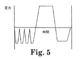
【0022】
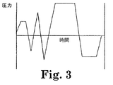
図3〜5は、普通に使用される3種の異なるプレバキュウム滅菌手法における圧力変化を経時的に示すグラフである。図3に示す手法は、酵素滅菌表示装置内で酵素の早期不活性化および偽陰性を生ずる可能性が低いものである。この手法では、真空を適用する前に蒸気を面菌チャンバーが注入される。滅菌サイクル中の初期圧力は、蒸気が滅菌チャンバーに注入されるときは大気圧に対して正であるが、真空がチャンバーに適用されると、大気圧に対して負となる。酵素滅菌表示装置が図3に示すものなどの滅菌サイクルに暴露されると、酵素は胞子が殺菌された直後に不活性化されるべきである。米国で最も普通に使用されるプレバキュウム蒸気手法では、真空が適用される前に蒸気が滅菌チャンバー内に注入された。
【0023】
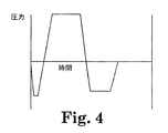
一方、図4〜5は、蒸気が導入される前に真空が滅菌チャンバーに適用される2つのプレバキュウム蒸気滅菌手法を図示する。欧州で普通に使用されるこれらの手法は、酵素滅菌表示装置において酵素の早期不活性化および偽陰性を生じやすい。図4に示す滅菌手法では、滅菌チャンバー内の圧力は、蒸気の導入前に真空が適用されたときには、大気圧に対して負となる。図5に示す滅菌サイクルでは、チャンバーが滅菌温度に到達する前に、4パルスの真空がチャンバーに適用され、その後蒸気が導入される。これらのサイクルにおける酵素不活性化の正確な機序は確かには不明であり、出願人は任意の特定の操作理論に結び付けたくはないが、酵素が濃縮された滅菌剤と接触するとき、不活性化されると考えられる。
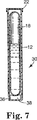
【0024】
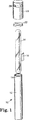
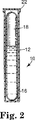
本発明の滅菌表示装置を図1および2に示す。滅菌表示装置10は、滅菌サイクルが終了するときまでに、系の種々の成分を互いに分離する入れ子状態の容器を含む。滅菌表示装置10は、外側管12、密封された内側管18および穴を開けた蓋26を備える。外側管12は、好ましくは、圧縮性プラスチック製である。内側管18はガラスまたはいくつかの他の壊れやすい材料製である。閉鎖部材22は、好ましくは、外側管12の開口端部14に適合する細菌不透過性で、ガス透過性障壁である。キャリヤー片16は、その表面に活性酵素源、微生物胞子または精製酵素を含み、内側管18と外側管12の壁の間に配置される。活性酵素源は、滅菌サイクル中の酵素の早期不活性化を防止するために、滅菌剤抵抗性化学物質で処理されている。内側管18は、キャリヤー片16上の酵素と反応して、滅菌手法が無効である場合に検出可能なシグナルを発生する基質を含有する。
【0025】
滅菌手法中、滅菌剤は蓋26の穴28を通って外側管12に流入して、キャリヤー片16の活性酵素源と接触するが、密封された内側管18内の基質溶液には接触しない。滅菌サイクル終了後、外側管12の側面を圧縮して、内側管18を破壊し、酵素と基質を互いに接触させる。次いで、残存する全ての活性酵素が基質と反応して、滅菌手法が無効であったかもしれないことを示す、発光、蛍光または色の変化などの検出可能なシグナルを発生する酵素修飾生成物を形成するのに十分な期間滅菌表示装置をインキュベーションする。
【0026】
本発明の滅菌表示装置10の好ましい実施態様において、キャリヤー片16上の活性酵素源は細菌または真菌胞子などの生きている微生物である。最も好ましい実施態様では、胞子が活性酵素源であり、滅菌表示装置10は、酵素活性および胞子の増殖を測定することによって滅菌手法の有効性をモニターする二重迅速読み出し表示装置である。この実施態様では、内側管18は胞子増殖培地および酵素基質を含有する。滅菌サイクルが終了したら、内側管18を破壊し、キャリヤー片16をその内容物に暴露し、インキュベーションする。酵素試験は数時間以内に目に見える結果を生じ、生きている微生物の増殖試験は7日以内にこれらの結果を確認する。
【0027】
酵素指標が作動する基礎理論は、酵素の不活性化が指標内の試験微生物の死滅に関連しているということである。生物学的指標に使用するために選択される酵素は、少なくとも汚染物質として存在する可能性がある微生物と同じくらい滅菌手法に抵抗性でなければならず、好ましくは、このような微生物よりさらに抵抗性でなければならない。酵素は、好ましくは、汚染微生物を殺菌できない滅菌サイクル後では検出可能な酵素−基質生成物を形成するが、汚染微生物を殺菌する滅菌サイクルによって不活性化されるのに十分な活性を保持しなければならない。
【0028】
本発明の滅菌表示装置に使用するのに好適な酵素および基質は米国特許第5,252,484号および米国特許第5,073,488号に記載されている。好適な酵素は、バシラス ステアロサーモフィラス(Bacillus stearothermophilus)およびバシラス サチリス(Bacillus subtilis)などの胞子形成微生物由来の酵素を含む。本発明の生物学的指標に有用である胞子形成微生物由来の酵素には、胞子形成微生物由来の、β−D−グルコシダーゼ、α−D−グルコシダーゼ、アルカリ性ホスファターゼ、酸性ホスファターゼ、ブチラートエステラーゼ、カプリレートエステラーゼリパーゼ、ミリステートリパーゼ、ロイシンアミノペプチダーゼ、バリンアミノペプチダーゼ、キモトリプシン、ホスホヒドロラーゼ、α−D−ガラクトシダーゼ、β−D−ガラクトシダーゼ、チロシンアミノペプチダーゼ、フェニルアラニンアミノペプチダーゼ、β−D−グルクロニダーゼ、α−L−アラビノフラノシダーゼ、N−アセチル−B−グルコサミノダーゼ、β−D−セロビオシダーゼ、アラニンアミノペプチダーゼ、プロリンアミノペプチダーゼおよび脂肪酸エステラーゼが含まれる。
【0029】
酵素と反応して検出可能な生成物を形成し、本発明の滅菌表示装置に使用するのに好適な色素生成基質および蛍光生成基質は当技術上周知である。(ロス(M.Roth)、生化学分析方法(Methods of Biochemical Analysis)、17巻、ブロック(D.Block)、編、インターサイエンスパブリッシャーズ(Interscience Publishers)、ニューヨーク、1969年、89ページ;ウデンフレンド(S.Udenfriend)、生物学および医学における蛍光アッセイ(Fluorescence Assay in Biology and Medicine)、アカデミックプレス(Academic Press)、ニューヨーク、1962年、312ページ;ローレンス(D.J.R.Lawrence)、酵素学者のための蛍光技法、酵素学における方法(Fluoresence Techniques for the Enzymologist,Methods in Enzymology)、4巻、コロウィック(S.P.Colowick)およびカプラン(N.O.kaplan)編、アカデミックプレス(Academic Press)、ニューヨーク、1957年、174ページ。これらの基質は、目で見て検出可能なシグナルを発生する様式に基づいて2つの群に分類することができる。第1の群の基質は酵素と反応して、自身が色素生成または蛍光生成である酵素修飾生成物を形成する。第2の群の基質は色または蛍光シグナルを発生するためにさらに化合物と結合しなければならない酵素修飾生成物を形成する。
【0030】
本発明の指標に使用する活性酵素源として働くのに特に好ましい微生物は、滅菌手法をモニターするために使用される胞子増殖指標内の試験微生物として普通に使用される微生物であるバシラス ステアロサーモフィラス(Bacillus stearothermophilus)およびバシラス サチリス(Bacillus subtilis)を含む。二重迅速読み出し表示装置を使用する場合には、これらの微生物は迅速酵素試験の活性酵素源および胞子増殖試験の試験微生物として働くことができる。バシラス ステアロサーモフィラス(Bacillus stearothermophilus)は蒸気および過酸化水素プラズマ滅菌手法をモニターするために特に好ましい。バシラス サチリス(Bacillus subtilis)はエチレンオキサイド滅菌手法をモニターするのに特に好ましく、過酸化水素プラズマ滅菌手法をモニターするために使用されることもある。ミネソタ州セントポールの3Mカンパニー(3M Company)製の登録商標3M登録商標ATTEST1291および1292迅速読み出し指標は、バシラス ステアロサーモフィラス(Bacillus stearothermophilus)の酵素α−D−グリコシダーゼの活性およびバシラス ステアロサーモフィラス(Bacillus stearothermophilus)の生きている胞子の増殖を測定する二重迅速読み出し表示装置である。
【0031】
本発明の滅菌表示装置に使用する滅菌剤抵抗性化学物質は、活性酵素源と結合すると、滅菌剤に対する酵素の抵抗性を増加し、その結果早期不活性化が回避されるいかなる化学物質であってもよい。滅菌表示装置10に使用する活性酵素源がバシラス ステアロサーモフィラス(Bacillus stearothermophilus)またはバシラス サチリス(Bacillus subtilis)などの微生物の胞子である場合には、好ましくは、それらをキャリヤー片16上に配置する前に滅菌剤抵抗性化学物質で処理する。
【0032】
滅菌剤抵抗性化学物質は、好ましくは、指標内の活性酵素源と結合したとき、滅菌チャンバー内に存在する汚染微生物を殺菌できないという点において無効である滅菌手法によって酵素が不活性化されることを防止する化学物質である。滅菌表示装置が、酵素活性および胞子の増殖の両方を測定する二重迅速読み出し表示装置である場合には、滅菌剤抵抗性化学物質は、好ましくは、活性酵素源と結合したとき、滅菌試験の増殖部分のために指標内に使用する試験微生物を殺菌するのに十分でない滅菌手法によって酵素活性が不活性化されるの防止する化学物質である。
【0033】
活性酵素源が本発明の滅菌剤抵抗性化学物質で処理されると、酵素は、好ましくは、滅菌をモニターするために普通に使用される少なくとも1種の試験微生物に対して亜致死的である滅菌サイクル後には、酵素に対する有効量の基質と反応して、24時間以内に検出可能な酵素修飾生成物を生成するのに十分な活性を有するが、酵素は、試験微生物に対して致死的である滅菌サイクル後にはバックグラウンドまで低下する活性を有する。最も好ましくは、本発明の滅菌剤抵抗性化学物質で処理した活性酵素源は、微生物の増殖の欠如によって測定したとき、1×10⁶試験微生物の集団をゼロまで低下するのに十分であると思われる滅菌サイクルを施した場合に、活性酵素と反応して検出可能な酵素修飾生成物を生成することができる有効量の基質との反応によって測定したとき、バックグラウンドに等しい活性を有するが、1×10⁶試験微生物の集団を少なくとも約1ログで、約6ログを超えない分だけ低下するのに十分な滅菌サイクルを施した場合に、基質の有効量と反応することによって測定したとき、バックグラウンドより高い活性を有する。
【0034】
本発明の好ましい実施態様において、滅菌剤抵抗性化学物質は、同一分子に疎水性領域と親水性領域とを有し、一般式RaLb(式中、Rは疎水性基であり、Lは浸水性基であり、aおよびbは各々1〜4までの数である)を有する界面活性剤である。Rは、好ましくは、炭素原子数少なくとも6、さらに好ましくは炭素原子数少なくとも8、最も好ましくは炭素原子数少なくとも12のアルキル基である。Lは、好適には、カルボキシル基およびそれらの塩、ヒドロキシル基、スルホネート基およびそれらの塩、硫酸基およびそれらの塩、リン酸塩、ホスホン酸塩、双性イオン性基、エチレンオキサイド/プロピレンオキサイドコポリマー基、ソルビタンまたはポリアルコキシル化ソルビタン基のエステルまたはエーテル、ポリアルコキシル化脂肪酸エステルまたはエーテル、ベタイン、構造−NHC(O)R’’’または−C(O)NHR’’’(式中、R’’’は水素または必要に応じてN、OおよびS原子によって利用可能な位置が置換されている炭素原子数1〜10のアルキル基である)を有するアミド基、短鎖アルコールまたは酸のエステル基、エーテル基、グリセロール単位1〜20、好ましくはグリセロール単位2〜12、さらに好ましくはグリセロール単位3〜10のポリグリセロールエステルまたはエーテル基、第二級アミン基並びに第三級アミン基を含む基から選択されてもよい。
【0035】
本発明の好ましい実施態様において、滅菌剤抵抗性化学物質は界面活性剤および疎水性添加剤を含んでもよい。疎水性添加剤は非水溶性で水に対して非自己分散性であると規定され、従って、界面活性剤による乳化が必要である。好適な疎水性添加剤は、室温において蝋または油である化合物を含む。滅菌剤抵抗性化学物質の一部として使用するのに適当な疎水性添加剤には、長鎖(直鎖または分岐鎖)アルキルまたはアルケニルアルコールまたは酸(C8−C36)の短鎖アルキルまたはアリールエステル(C1−C6)およびそれらのポリエトキシル化誘導体、必要に応じて−OHによって利用可能な位置が置換されているC4−C12二酸またはジオールの短鎖アルキルまたはアリールエステル(C1−C6)、グリセロール、ペンタエリスリトール、エチレングリコールのアルキルまたはアリールC1−C9エステル、ポリプロピレングリコールのC12−C22アルキルエステルまたはエーテル、ポリプロピレングリコール/ポリエチレングリコールコポリマーのC12−C22アルキルエステルまたはエーテル、ポリエーテルポリシロキサンコポリマー、環状ジメチコーン、ポリジアルキルシロキサン、ポリアリール/アルキルシロキサン、長鎖の直鎖または分岐鎖アルキルまたはアルケニルアルコールまたは酸の長鎖(C8−C36)アルキルおよびアルケニルエステル、長鎖の直鎖または分岐鎖(C8−C36)アルキルまたはアルケニルアミンまたは酸の長鎖(C8−C36)アルキルまたはアルケニルアミド、スクアレン、スクアラン、ポリエチレンワックス、ラノリン、ワセリンおよび鉱物油などの直鎖および分岐鎖アルカンおよびアルケンを含む炭化水素、ポリシロキサンポリアルキレンコポリマー、ジアルコキシジメチルポリシロキサン、必要に応じてOHによって利用可能な位置が置換されたC12−C22二酸またはジオールの短鎖アルキルまたはアリールエステル(C1−C6)並びにC12−C22アルキルおよびアルケニルアルコールが含まれる。好適な疎水性添加剤にはイソステアリルアルコール、セチルアルコール、ジイソプロピルアジペート、スクアラン、鉱物油、イソプロピルミリステート、ジメチコン、ラノリンおよびワセリンが含まれる。
【0036】
別の好ましい実施態様において、滅菌剤抵抗性化学物質はポリグリセロールアルキルエステルもしくはエーテル、またはポリグリセロールアルキルエステルもしくはエーテルを含む化学物質の混合物である。別の好ましい実施態様において、滅菌剤抵抗性化学物質はエトキシル化グリセロールエステルもしくはエーテル、またはエトキシル化グリセロールエステルもしくはエーテルを含む化学物質の混合物である。好ましい実施態様において、滅菌剤抵抗性化学物質はまたデカグリセロール、ソルビトールまたはそれらの一方を含む化学物質の混合物を含んでもよい。別の好ましい実施態様において、滅菌剤抵抗性化学物質はデカグリセロールモノステアレートとソルビトールの混合物である。
【0037】
滅菌剤抵抗性化学物質として使用することができるポリグリセロールアルキルエステルまたはエーテルは、式、
【化1】
この式において、nは0〜50であり、RはHまたは式R’または
【化2】
【0038】
本発明において滅菌剤抵抗性化学物質として使用するのに好ましいポリグリセロールアルキルエステルまたはエーテルには、デカグリセリルモノステアレート、ヘキサグリセリルモノステアレート、テトラグリセリルモノステアレート、ヘキサグリセリルポリリシノレート、デカグリセリルモノラウレート、テトラグリセリルモノオレエート、デカグリセリルトリオレエート、デカグリセリルモノオレエート、デカグリセリルジパルミテート、ヘキサグリセリルジステアレート、デカグリセリルモノオレエート、デカグリセリルモノミリステート、デカグリセリルモノイソステアレート、デカグリセリルジイソステアレート、ヘキサグリセロールモノラウレート、テトラグリセリルモノオレエートおよびデカグリセリルトリオレエートが含まれる。
【0039】
滅菌剤抵抗性化学物質として使用することができるエトキシル化グリセロールエステルまたはエーテルは式、
【化3】
この式において、nは0〜50であり、R’’はN、OおよびSによって利用可能な位置が置換されていてもよいC5〜C50直鎖または分岐鎖アルキル、アルキレン、アラルキルまたはアラルケニル基であってもよく、R’’’はHまたはN、OおよびSによって利用可能な位置が置換されていてもよいC1〜C50直鎖または分岐鎖アルキル、アルキレン、アラルキルまたはアルケニル基であってもよい。好ましくは、R’’は炭素原子数6〜20の直鎖アルキル基であり、nは2〜10であり、R’’’は炭素原子数6〜20の直鎖アルキル基である。
【0040】
滅菌剤抵抗性化学物質として使用するのに特に好ましいエトキシル化グリセロールエステルまたはエーテルには、グリセレス(glycereth)−7−ジイソノナノエートおよびポリオキシセチレン(polyoxythethylene)(5)グリセリルモノステアレートが含まれる。
【0041】
本発明の滅菌表示装置10は、米国特許第5,252,484号および米国特許第5,073,488号に記載する方法により製造される。滅菌表示装置10の活性酵素源として胞子を使用する場合、胞子を培養皿で増殖し、次いで取り出し、水に懸濁させ、遠心分離して逐次的に洗浄する。次いで、胞子を滅菌剤抵抗性化学物質を含有する溶液に懸濁させ、ピペット操作によりキャリヤー片16に移す。いかなる数の胞子を滅菌表示装置10に使用するキャリヤー片16に適用することができるが、本発明の好ましい実施態様では1×10⁶の胞子を各キャリヤー片に移す。
【0042】
当業者は、本発明を実施する際に使用する種々の滅菌剤抵抗性化学物質の最適濃度を意図されていない実験を実施することなく確認することができる。従って、本発明は、任意の特定濃度または任意の範囲の濃度の同定されている化学物質の使用に限定されない。しかし、滅菌剤抵抗性化学物質の好ましい濃度は以下のようである。
【0043】
【表1】
本発明の滅菌表示装置は、好適に、蒸気、過酸化水素蒸気相、過酸化水素プラズマ、エチレンオキサイドガス、乾式加熱、プロピレンオキサイドガス、臭化メチル、二酸化塩素、ホルムアルデヒドおよび過酢酸(単独または蒸気相と併用して)並びに任意の他のガス状または液体薬剤を使用する滅菌手法を含む任意の種類の滅菌手法の有効性をモニターするために使用することができる。さらに好ましくは、酵素が滅菌サイクル中に早期に不活性化されるリスクが存在する滅菌手法の有効性をモニターするために生物学的指標を使用することができる。本発明の滅菌表示装置は、最も好ましくは、図4および5のグラフによって示されるものなどの、蒸気が導入される前に真空がチャンバー内に適用される条件相を使用して、蒸気滅菌方法の有効性をモニターするために使用される。
【0045】
本発明の別の実施態様において、滅菌表示装置10は、詳細には、過酸化水素プラズマ滅菌手法中の早期不活性化に特に抵抗性を示す1種以上の滅菌剤抵抗性化学物質で活性酵素源を処理することによって、過酸化水素プラズマ滅菌手法の有効性をモニターする際に使用するために製造される。これらの指標は単独または滅菌表示装置以外にトレーおよび蓋を含む試験パックの一部として使用することができる。以下に考察するように、試験パックのデザインは、過酸化水素プラズマ手法に種々の量のさらなる抵抗性を滅菌表示装置に与えるように適合させることができる。一実施態様において、試験パックは単独で使用される指標の抵抗性と比較してさらなる抵抗性を与えないことがあり、別の実施態様において、試験パックは、所定の断面積および長さを有する内腔内に配置された場合に指標が経験すると思われる追加の抵抗性と同等の追加の抵抗性を指標に与えることができる。
【0046】
本発明の滅菌表示装置は、例えば、米国特許第4,643,876号に記載される手法を含む、当技術上周知の過酸化水素プラズマ滅菌手法の任意のものの有効性をモニターするために使用することができる。
【0047】
本発明の好ましい実施態様において、本発明の過酸化水素プラズマ指標は、上記のように、活性酵素源が1種以上の滅菌剤抵抗性化学物質で処理されている酵素指標または二重迅速読み出し表示装置である。好適な滅菌剤抵抗性化学物質には、デカグリセリルデカオレエート、デカグリセロールペンタオレエート、テトラグリセロールモノオレエート、デカグリセリルトリオレエート、デカグリセロールヘキサノエート、ヘキサグリセロールジオレエート、ポリオキシエチレン(60)グリセロールモノステアレート、ポリオキシエチレン(20)ソルビタンモノステアレートおよびヘキサグリンジステアレートが含まれる。
【0048】
好適な滅菌剤抵抗性化学物質は、式、
【化4】
この式において、R1、R2およびR3は、Hまたは
【化5】
【0049】
本発明の好ましい実施態様において、過酸化水素プラズマ指標は、微生物の胞子が活性酵素試験の活性酵素源および胞子増殖試験の試験微生物として働く二重迅速読み出し表示装置である。好適な微生物はバシラス ステアロサーモフィラス(Bacillus stearothermophilus)およびバシラス サチリス(Bacillus subtilis)を含む。最も好ましい実施態様において、バシラス ステアロサーモフィラス(Bacillus stearothermophilus)の胞子が指標に使用される。
【0050】
過酸化水素プラズマ指標に使用するための胞子は、上記の手法を使用して滅菌剤抵抗性化学物質で処理される。培養した胞子を培養皿から取り出し、水に懸濁させてから遠心分離して逐次的に洗浄する。次いで、所定の数の胞子、好ましくは1×10⁶を滅菌剤抵抗性化学物質を含有する溶液に懸濁させ、キャリヤー片16に移す。当業者は、本発明を実施する際に使用する種々の滅菌剤抵抗性化学物質の最適濃度を意図されていない実験を実施することなく確認することができる。従って、本発明は、任意の特定濃度または任意の範囲の濃度の同定されている化学物質の使用に限定されない。しかし、過酸化水素プラズマ滅菌手法に使用するための滅菌剤抵抗性化学物質の好ましい濃度は以下のようである。
【0051】
【表2】
過酸化水素プラズマ手法に使用するための滅菌表示装置は、好ましくは、上記の方法により製造され、図1に示す表示10の構成を有する。しかし、指標が過酸化水素プラズマ手法をモニターするために使用される場合には、閉鎖部材22は、好ましくは、デラウェアー州ウィルミントンのイー アイ デュポン デ ネモアーズ アンド コ(E.I.du Pont de NeMours and Co.)製の登録商標TYVEK高密度ポリエチレン繊維材料などの高密度繊維材料製である。
【0053】
使用時には、滅菌表示装置10は滅菌チャンバー内に配置され、過酸化水素プラズマ滅菌手法に暴露される。滅菌剤は開口部28および閉鎖部材22を通って表示装置10に流入し、酵素キャリヤー16上に配置された活性酵素源と接触する。手法が終了したら、表示装置10を滅菌チャンバーから取り出し、外側管12の側面を圧縮し、壊れやすい内側管18を破壊して酵素基質を放出させ、その結果酵素基質はキャリヤー片16上の酵素源と接触することができる。次いで、表示内に残存する全ての活性化酵素が基質と反応して、滅菌手法の失敗の検出可能な指標となる酵素修飾生成物を形成するのに十分な時間滅菌表示装置10をインキュベーションする。酵素修飾生成物は蛍光、発光または色の変化として検出可能であってもよい。滅菌表示装置が有効で、全ての活性酵素が不活性化されている場合には、インキュベーションの結果検出可能なシグナルは生成されない。
【0054】
図6〜7に示す、過酸化水素プラズマ滅菌手法に使用するための滅菌表示装置30のさらに好ましい実施態様において、酵素キャリヤー36が管の密閉端部付近の外側管12内に配置され、キャリヤー片36と内側管18の間にバリヤー38が配置される。バリヤーは、好ましくは、ミネソタ州セントポールの3Mカンパニー(3M Company)製の「登録商標THINSULATE200−Bブランドサーマルインシュレーション(Thermal Insulation)」として購入可能な、200g/平方メーターの重量を有するポリプロピレンのブロー成形されたマイクロ繊維材料のディスクである。
【0055】
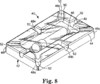
本発明の滅菌表示装置のいかなるものも10および30、試験パックの一部として使用することができる。図8に示す、本発明の一実施態様では、本発明の非−抵抗性試験パック40は、滅菌表示装置10単独の抵抗性を上回る、滅菌手法に対する追加の抵抗性を提供しない。非−抵抗性試験パックは、滅菌手法中に滅菌表示装置を1箇所にしっかりと保持するという点において、試験パックを使用しない表示装置を使用するよりも利点を提供する。従って、非−抵抗性試験パックは、一般に小型で、転がりやすい滅菌表示装置が、滅菌手法中に材料を添加する際にずれるまたは置き違えられる場合に生ずる問題を軽減する。
【0056】
非−抵抗性滅菌試験パック40は、滅菌表示装置10を保持するためのプラスチックトレー42と、滅菌表示装置10自体による抵抗性以外にはいかなる抵抗も受けることなく滅菌剤が自由に試験パックに流入し、滅菌表示装置と接触するように、トレー42に結合したプラスチック製の蓋50とを備える。プラスチックトレー42はいかなる形状であってもよいが、好ましくは矩形または正方形である。プラスチックトレー42は、トレーの全周を規定する隆起した縁面44と、滅菌手法中に滅菌表示装置10をその場所に保持するためのへこんだ窪み46を含む。間隔をおいて離れた複数の溝48a〜48fがトレー42の全周の蓋面44に形成され、蓋50の表面とともに一連の通路52を形成する。通路は、通路を通る滅菌剤の流動に大きな障害を生ずることなく、試験パックの外側から滅菌表示装置10まで滅菌剤を通すのに断面積が十分に大きくあるべきである。好ましい実施態様において、通路は、直径0.25インチ(0.635cm)の円の面積とほぼ同じ断面積を有し、トレーの各コーナーに1つ、各側面に1つの6つの通路が存在する。しかし、通路の数およびそれらの直径は本発明の範囲から逸脱することなく変更することができることは当業者に容易に明らかになる。
【0057】
好ましくは、蓋50と蓋50に接触する縁面44は、滅菌剤に対して実質的に不透過性である密封を形成する。このような密封は、好ましくは、蓋50の面と縁面44との間に互いに接触する接着剤層を配置することによって形成することができる。さらに好ましくは、プラスチック蓋50を縁面44にヒートシール処理することによって密封を形成することができる。
【0058】
滅菌手法中、通路は、滅菌チャンバーから滅菌表示装置10までへこんだ窪み46を通過させる。以前に記載したように、滅菌剤は表示装置10に流入し、活性酵素源と接触する。次いで、表示装置10を非−抵抗性試験パック40から取り出し、外側管18を圧縮し、内側管18を破壊し、基質を放出させ、その結果、基質はキャリヤー片16上の酵素と接触することができる。次いで、基質が全ての活性酵素と反応し、検出可能な酵素修飾生成物を形成するのに十分な期間の間表示装置10をインキュベーションする。酵素修飾生成物は、蛍光、発光または色の変化などのシグナルとして検出可能であることができる。検出可能な酵素修飾生成物がみられることは、滅菌チャンバーに存在する汚染微生物を殺菌していない可能性があるという点において滅菌手法が失敗したことを示している。
【0059】
非−抵抗性試験パック40のトレー42および蓋50は、好ましくは、耐熱性で、滅菌手法後に残存滅菌剤を含有しないプラスチック製である。本明細書に使用する用語「耐熱性」は、変形、縮み、融解または分解することなく個々の滅菌手法中に達成される最高温度に耐えることができることを意味する。滅菌手法中に達成される最高温度は、使用する滅菌手法の種類に応じて異なる。例えば、多数の蒸気滅菌手法は121℃以上の温度において実施されるが、過酸化水素プラズマ滅菌手法は普通には60℃より低い温度で実施される。トレーに使用するための適切な耐熱性プラスチックを選択する際に、種々の滅菌手法間のこのような温度差が適切に考慮されなければならず、表示装置を使用する滅菌手法の最大温度より高いガラス転移温度を有するプラスチックが選択されるべきである。
【0060】
過酸化水素プラズマ滅菌手法に使用するのに好適な非−抵抗性試験パックの好ましい実施態様において、トレーはグリコール添加剤を有するポリエチレンテレフタレート(PETG)製である。試験パックトレー42に使用するのに好適な耐熱性プラスチックの他の例にはポリ塩化ビニル、ポリエチレン、超高分子量ポリエチレン、ポリエテラミド、ポリスルホン、クロロトリフルオロエチレン、ポリフッ化ビニル、ポリテトラフルオロエチレン(PTFE)、ポリプロピレン、ポリスチレンおよびポリエステルが含まれる。
【0061】
蓋50はトレー42と同じ材料で製造されてもよい。好ましくは、蓋20は、半透明または透明なプラスチック材料製である。過酸化水素プラズマ滅菌手法に使用するのに好適な最も好ましい実施態様において、蓋50は透明なフィルム製であり、リム面44にヒートシール処理される。好適な透明フィルムの例は、ミネソタ州セントポールの3Mカンパニー(3M Company)製の登録商標SCOTCHPAKポリエステルフィルムとして購入可能なポリエチレンとエチレンビニルアセテートのブレンドをコーティングしたポリエステルフィルムである。
【0062】
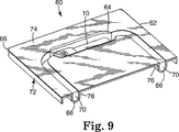
図9は、所定の断面積および長さを有する内腔内に配置された場合に表示装置が経験すると思われる抵抗性と同等の滅菌表示装置に対する追加の抵抗性を提供する、内腔−抵抗性試験パックとして本明細書においていわれる別の試験パックを示す。内腔−抵抗性試験パックは、管様機器の内部深くに位置していることがある微生物を殺菌する際に滅菌手法が有効であるかどうかを判定する正確な方法を提供する。
【0063】
内腔−抵抗性試験パック60は、滅菌表示装置10を保持するトレー72と蓋68とを有する。トレー72は耐熱性プラスチック製で、トレー72の全周を規定する端部62を有する実質的に平坦な面74を有する。滅菌表示装置10を保持するための窪み64が平坦な面74に形成される。所定の長さを有する溝66が平坦な面に形成されて、へこんだ窪み64を通って延在し、2箇所76および78で端部62を貫通する連続通路を形成する。蓋68は、滅菌剤に対して実質的に不透過性である実質的に平坦な面74で密封を形成する。平坦な面74と互いに接触している蓋68の面との間に接着剤層を形成することによって、またはヒートシール処理をすることによって密封を形成することができる。蓋68と溝66との間の空間は、接着剤が滅菌チャンバーから滅菌表示装置10まで通過される内腔通路70を規定する。
【0064】
内腔通路70は所定の長さおよび断面積を有する。内腔通路の寸法は、既知の寸法を有する内腔内の条件を複製するように選択または適合することができる。好ましくは、過酸化水素プラズマ滅菌手法の有効性を試験するために使用することができる試験パックの好ましい実施態様では、内腔通路は長さほぼ約12インチ(30.48cm)で、直径0.25インチ(0.635cm)を有する円の面積に近い断面積を有する。しかし、任意の内腔長さおよび断面積を選択してもよく、全て本発明の範囲内であると考えられる。例えば、図10は、内腔通路が図8に示す内腔通路70と長さが異なる内腔−抵抗性試験パック80の別の実施態様を示す。
【0065】
使用時には、試験パック60は滅菌チャンバー内に配置され、滅菌手法に暴露され、滅菌手法中に滅菌剤は内腔通路76を移動し、滅菌表示装置10に接触する。手法の終了時に、滅菌表示装置10を試験パックから取り出し、非−抵抗性試験パックを参照して上記のように取り扱う。
【0066】
トレー72および蓋68は、非−抵抗性試験パックに関して上記した方法で選択するべきである耐熱性プラスチック材料製である。過酸化水素プラズマ手法に使用するのに好適な好ましい実施態様において、トレー72はグリコール添加剤を有するポリエチレンテレフタレート(PETG)製であり、蓋はミネソタ州セントポール3Mカンパニー(3M Company)製の登録商標SCOTCHPAKポリエステルフィルムとして購入可能なポリエチレンとエチレンビニルアセテートのブレンドを含む透明フィルム製である。フィルム68はトレー72にヒートシール処理されることができる。
【0067】
本発明の操作は、以下の詳細な実施例に関してさらに記載される。これらの実施例は、種々の特定で、好ましい実施態様および技法をさらに例示するために提供される。しかし、多数の変更および改良を加えることができるが、本発明の範囲内にとどまることが理解されるべきである。
【0068】
実施例
実施例1〜5は、表1〜5に掲載する化学物質で処理してある胞子を用いて製造した滅菌表示装置が、プレバキュウム蒸気滅菌サイクルにおける酵素の早期不活性化に対する抵抗性を増加させることを実証しているかどうかを判定する試験結果を報告する。実施例6〜9は、表6〜9に掲載する化学物質で処理してある胞子を用いて製造した滅菌表示装置が、過酸化水素プラズマ滅菌手法における酵素の早期不活性化に対する抵抗性を増加させることを実証しているかどうかを判定する試験結果を報告する。実施例10は、本発明の非−抵抗性試験パックおよび内腔−抵抗性試験パックの有効性を実証する試験結果を報告する。
【0069】
表示装置の製造
実施例1〜5の滅菌表示装置は、米国特許第5,252,484号に記載されている方法により、図1および2に例示するように構成した。これらの実施例のために製造した表示装置は、迅速な酵素に基づいた有効性試験と確証的な胞子増殖試験を提供する二重迅速読み出し表示装置であった。キャリヤー片16上にコーティングした胞子は、その活性が迅速な酵素試験によって測定される活性酵素源として働いた。次いで、これらの同じ胞子を試験の胞子増殖部分でインキュベーションする。
【0070】
メリーランド州ロックビルのアメリカン タイプ カルチャー コレクション(American Type Culture Collection)のATCC7953として市販品を購入可能なバシラス ステアロサーモフィラス(Bacillus stearothermophilus)をトリプシンダイズブロス中で58℃において終夜(16時間)増殖させた。この培養物を使用して、8g/l栄養ブイヨン、4g/l酵母抽出液、0.1g/l塩化マンガンおよび20g/l寒天からなるpH7.2の寒天平板培地の表面に接種した。58℃において72時間平板番地をインキュベーションした。胞子を培養皿からかき取り、滅菌した蒸留水に懸濁させた。懸濁液を7000rpm、4℃において20分間遠心分離することによって、胞子を栄養片から分離した。上清を注いで除き、胞子を滅菌した蒸留水に再度懸濁させた。洗浄手法を数回反復した。最後の洗浄後、1ミリリッターあたり約1×108胞子濃度で胞子を滅菌した蒸留水に懸濁させた。
【0071】
次いで、表1〜5に同定した化学物質で胞子を処理した。試験した全ての化学物質は販売元から入手した。胞子は6000rpmで10分間遠心分離した。上清を取り、表に示す濃度のコーティング化学物質と混合した。上清とコーティング化学物質の混合物を60〜80℃において数分間加熱し、撹拌して材料を溶液にした。次いで、胞子を滅菌剤抵抗性化学物質溶液に混合した。10〜15マイクロリッターを各片に分注することによって、滅菌剤抵抗性化学物質溶液を5×25mm、591A紙製キャリヤー片に適用し、1キャリヤー片あたり約1×10⁶胞子の最終集団とした。キャリヤー片を37℃において16時間乾燥した。
【0072】
処理した胞子キャリヤー片を表示装置10の外側容器12の底部に配置し、胞子キャリヤー片16と酵素基質を含有する内側容器18との間にバリヤーを挿入した。ミネソタ州セントポールの3Mカンパニー(3M Company)製の「登録商標THINSULATE200−Bブランドサーマルインシュレーション(Thermal Insulation)」として購入可能な重量200g/m2のポリプロピレンブロー成形マイクロ繊維材料の1.75mm(11/16インチ)ディスクをバリヤーとして使用した。内側容器18は、1リッターの水あたり、17gの細菌ペプトンおよび0.17g/lのL−アラニン並びに200マイクロリッターのN,N−ジメチルホルムアミドに溶解したミズーリ州セントルイスのシグマ ケミカル カンパニー(Sigma Chemical Company)から購入可能な0.1gの4−メチルウンベリフェリル−α−D−グルコシド、および0.03gのブロモクレゾールパープルpH指示薬染料からなる0.67mlの栄養培地を含有した。酵素基質および栄養培地溶液のpHは0.1N水酸化ナトリウムで7.6に調整した。
【0073】
外側バイアル12およびキャップ26は共にポリプロピレン製である。外側のバイアル12は長さ5.08cm(2.0インチ)で、外径85.1mm(0.335インチ)、内径77.0mm(0.303インチ)であった。キャップ26は長さ1.275cm(0.510インチ)で、内径83.3mm(0.328インチ)であった。内側容器18はガラス製で、長さ3.96cm(1.56インチ)で、外径65.5mm(0.258インチ)で、壁厚2.5mm(0.10インチ)であった。閉鎖部材22は、直径1.27mm(0.5インチ)の滅菌グレードのろ紙片であった。
【0074】
実施例6〜9の滅菌表示装置は、滅菌表示装置の閉鎖部材22をデラウェアー州ウィルミントンのイー アイ デュポン デ ネモアーズ アンド コ(E.I.du Pont de NeMours andCo.)から購入可能な登録商標TYVEK高密度ポリエチレン繊維材料で構成した以外は上記のように製造した。
【0075】
実施例1
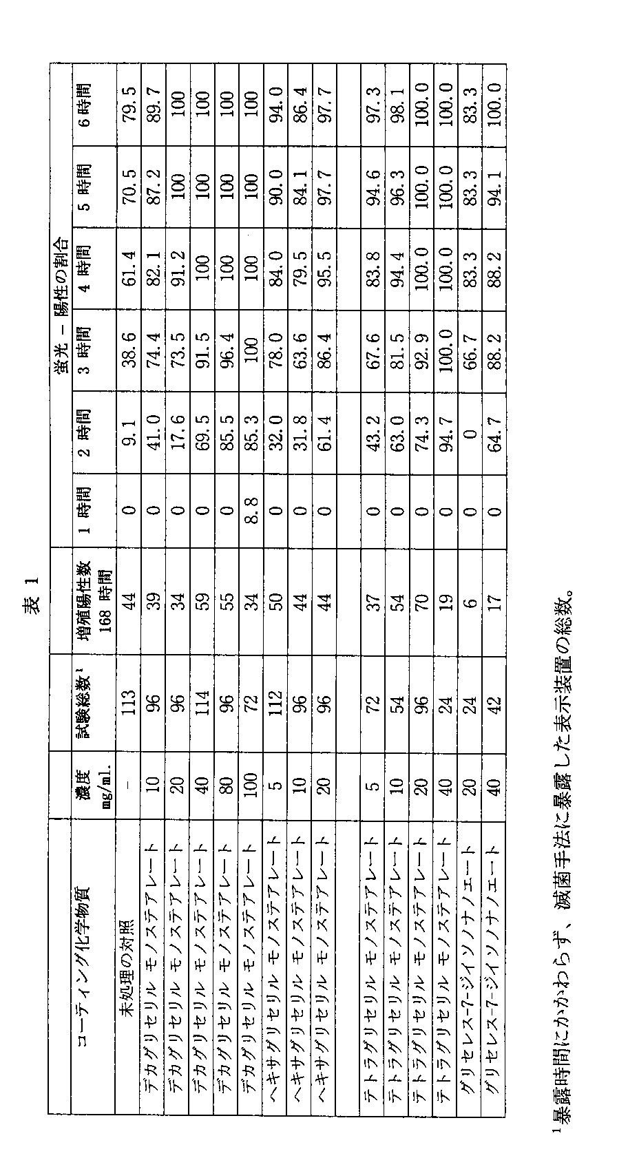
この実施例は、表1の化学物質で処理した胞子を用いて製造した滅菌表示装置は、未処理の胞子を用いた表示装置と比較したとき、正確さの改善を実証することを提供している。表1の化学物質はポリグリセロールアルキルエステルまたはエトキシル化グリセロールエステルである。
【0076】
表1に記載する化学物質および濃度の各々を用いて上記のように滅菌表示装置を製造した。未処理の胞子を使用して対照の表示装置を製造した。表示装置を金属製の機器トレーに配置し、各パルスについて真空レベル0.075〜0.085barおよび1.00barまでの蒸気パルスを用いた121℃における4−パルスプレバキュウムサイクルを使用して、121℃においてゲチンゲ スチーム ステリライザー(Getinge Steam Sterilizer)(ゲチンゲ インターナショナル インク(Getinge International,Inc.)、1100タウビン アベニュー、ニュージャージー州レイクウッド)に暴露した。表示装置を7〜13分間滅菌剤に暴露した。このサイクルは、図5の時間−圧力ダイアグラムに図示されている。暴露後、酵素基質および栄養培地を含有する内側容器を破壊し、表示装置を60℃においてインキュベーションした。ミネソタ州セントポールの3Mカンパニー(3M Company)から購入可能な登録商標3M登録商標ATTESTモデル190ラピッド オートリーダー(Rapid Autoreader)を使用して表示装置を蛍光について調査した。また、紫から黄色への色の変化によって示されるように、60℃における168時間のインキュベーション後に胞子の増殖を目で見て判定した。
【0077】
試験した化学物質は販売元から入手した。デカグリセロールモノステアレート、ヘキサグリセリルモノステアレートおよびテトラグリセリルモノステアレートは日本、東京のニッコー ケミカルズ コ(Nikko Chemicals Co.)から入手した。グリセレス−7−ジイソノナノエートはニュージャージー州マタワンのアルゾ コ(Alzo Co.)から入手した。
【0078】
168時間のインキュベーション後に検出された増殖陽性の表示装置の数を表1に記録する。1時間、2時間、3時間、4時間、5時間および6時間経過時に蛍光を示したこれらの増殖陽性の表示装置の割合も表1に記録する。表1の滅菌表示装置の正確さを判定するために、100%の蛍光陽性の割合が完璧であり、これは、全ての増殖陽性が蛍光陽性として検出され、偽陰性は検出されないことを示している。一方、100%より低い蛍光陽性数は、蛍光が陰性であった表示装置の中には、後に胞子の増殖が陽性であると検出されるものがあるという点において、1つ以上の偽陰性があったことを示す。
【0079】
【表3】
実施例2
この実施例は、未処理の胞子を用いて製造した表示装置と比較したとき、処理した胞子を用いて製造した滅菌表示装置の正確さに対して、アルキルエステルまたはエーテルを持たないポリグリセロール化合物で胞子を処理することが与える影響の証拠を提供する。
【0081】
表2に示す化学物質と濃度の各々を用いて上記のように滅菌表示装置を製造した。未処理の胞子を使用して、対照表示装置を製造した。表示装置を金属製の機器トレーに配置し、各パルスについて真空レベル0.075〜0.085barおよび1.00barまでの蒸気パルスを用いた121℃における4−パルスプレバキュウムサイクルを使用して、121℃においてゲチンゲ スチーム ステリライザー(Getinge Steam Sterilizer)(ゲチンゲ インターナショナル インク(Getinge International,Inc.)、1100タウビン アベニュー、ニュージャージー州レイクウッド)に暴露した。表示装置を7〜13分間滅菌剤に暴露した。このサイクルは、図5の時間−圧力ダイアグラムに図示されている。暴露後、酵素基質および栄養培地を含有する内側容器を破壊し、表示装置を60℃においてインキュベーションした。ミネソタ州セントポールの3Mカンパニー(3M Company)から購入可能な登録商標3M登録商標ATTESTモデル190ラピッド オートリーダー(Rapid Autoreader)を使用して表示装置を蛍光について調査した。また、紫から黄色への色の変化によって示されるように、60℃における168時間のインキュベーション後に胞子の増殖を目で見て判定した。
【0082】
168時間のインキュベーション後に検出された増殖陽性の表示装置の数を表2に記録する。1時間、2時間、3時間、4時間、5時間および6時間経過時に蛍光を示したこれらの増殖陽性の表示装置の割合も表2に記録する。表2の滅菌表示装置の正確さを判定するために、100%の蛍光陽性の割合が完璧であり、これは、全ての増殖陽性が蛍光陽性として検出されることを示している。一方、100%より低い蛍光陽性数は、蛍光が陰性であった表示装置の中には、後に胞子の増殖が陽性であると検出されるものがあるという点において、1つ以上の偽陰性があったことを示す。
【0083】
胞子コーティングとして使用したとき、ヘキサグリセロールおよびトリグリセロールは滅菌表示装置の正確さを改善しなかった。
【0084】
試験した化学物質は販売元から入手した。デカグリセロール、ヘキサグリセロールおよびトリグリセロールはニュージャージー州フェアローンのロンザ インク(Lonza,Inc.)から入手した。
【0085】
【表4】
実施例3
この実施例は、デカグリセリルモノステアレートとソルビトールの混合物またはデカグリセロールモノステアレート単独で処理した胞子を用いて製造した滅菌表示装置は、未処理の胞子またはソルビトール単独で処理した胞子を用いて製造した滅菌表示装置と比較したとき、正確さの改善を実証するという証拠を提供する。
【0087】
表3に記載する化学物質および濃度の各々を用いて上記のように滅菌表示装置を製造した。未処理の胞子を使用して対照の表示装置を製造した。表示装置を金属製の機器トレーに配置し、各パルスについて真空レベル0.075〜0.085barおよび1.00barまでの蒸気パルスを用いた121℃における4−パルスプレバキュウムサイクルを使用して、121℃においてゲチンゲ スチーム ステリライザー(Getinge Steam Sterilizer)(ゲチンゲ インターナショナル インク(Getinge International,Inc.)、1100タウビン アベニュー、ニュージャージー州レイクウッド)に暴露した。表示装置を7〜15分間滅菌剤に暴露した。このサイクルは、図5の時間−圧力ダイアグラムに図示されている。暴露後、酵素基質および栄養培地を含有する内側容器を破壊し、表示装置を60℃においてインキュベーションした。ミネソタ州セントポールの3Mカンパニー(3M Company)から購入可能な登録商標3M登録商標ATTESTモデル190ラピッド オートリーダー(Rapid Autoreader)を使用して表示装置を蛍光について調査した。また、紫から黄色への色の変化によって示されるように、60℃における168時間のインキュベーション後に胞子の増殖を目で見て判定した。
【0088】
168時間のインキュベーション後に検出された増殖陽性の表示装置の数を表3に記録する。1時間、2時間、3時間、4時間、5時間および6時間経過時に蛍光を示したこれらの増殖陽性の表示装置の割合も表3に記録する。表2の滅菌表示装置の正確さを判定するために、100%の蛍光陽性の割合が完璧であり、これは、全ての増殖陽性が蛍光陽性として検出されることを示している。一方、100%より低い蛍光陽性数は、蛍光が陰性であった表示装置の中には、後に胞子の増殖が陽性であると検出されるものがあるという点において、1つ以上の偽陰性があったことを示す。
【0089】
試験した化学物質は販売元から入手した。ソルビトールはミネソタ州ミネアポリスのパドック ラボラトリーズ(Paddock Laboratories)から入手した。デカグリセリルモノステアレートは日本、東京のニッコー ケミカルズ コ(Nikko Chemicals Co.)から入手した。
【0090】
【表5】
実施例4
この実施例は、表4の化学物質は、滅菌表示装置に使用する胞子を処理するために使用した場合に、未処理の胞子を用いて製造した表示器と比較したとき、表示器の正確さを改善する証拠を提供する。
【0092】
表4に記載する化学物質および濃度の各々を用いて上記のように滅菌表示装置を製造した。未処理の胞子を使用して対照の表示装置を製造した。表示装置を金属製の機器トレーに配置し、各パルスについて真空レベル0.075〜0.085barおよび1.00barまでの蒸気パルスを用いた121℃における4−パルスプレバキュウムサイクルを使用して、121℃においてゲチンゲ スチーム ステリライザー(Getinge Steam Sterilizer)(ゲチンゲ インターナショナル インク(Getinge International,Inc.)、1100タウビン アベニュー、ニュージャージー州レイクウッド)に暴露した。表示装置を7〜18分間滅菌剤に暴露した。このサイクルは、図5の時間−圧力ダイアグラムに図示されている。暴露後、酵素基質および栄養培地を含有する内側容器を破壊し、表示装置を60℃においてインキュベーションした。ミネソタ州セントポールの3Mカンパニー(3M Company)から購入可能な登録商標3M登録商標ATTESTモデル190ラピッド オートリーダー(Rapid Autoreader)を使用して表示装置を蛍光について調査した。また、紫から黄色への色の変化によって示されるように、60℃における168時間のインキュベーション後に胞子の増殖を目で見て判定した。
【0093】
168時間のインキュベーション後に検出された増殖陽性の表示装置の数を表4に記録する。1時間、2時間、3時間、4時間、5時間および6時間経過時に蛍光を示したこれらの増殖陽性の表示装置の割合も表4に記録する。表4の滅菌表示装置の正確さを判定するために、100%の蛍光陽性の割合が完璧であり、これは、全ての増殖陽性が蛍光陽性として検出されることを示している。一方、100%より低い蛍光陽性数は、蛍光が陰性であった表示装置の中には、後に胞子の増殖が陽性であると検出されるものがあるという点において、1つ以上の偽陰性があったことを示す。
【0094】
滅菌表示装置の正確さは、表示装置に使用する胞子をデカグリセリルモノステアレート、デカグリセリルモノラウレート、ヘキサグリセリルモノラウレート、テトラグリセリルモノオレエート、デカグリセリルモノオレエート、デカグリセロールジパルミテートおよびヘキサグリセリルジステアレートで処理したとき、改善された。胞子をより高濃度の化学物質で処理すると、この影響は増加した。
【0095】
試験した化学物質は販売元から入手した。デカグリセロールモノステアレート、ヘキサグリセリルポリリシノレート、ヘキサグリセリルペンタオレエート、デカグリセリルモノラウレート、ヘキサグリセリルモノラウレート、テトラグリセリルモノオレエートおよびデカグリセリルトリオレートは日本、東京のニッコー ケミカルズ コ(Nikko Chemicals Co.)から入手した。デカグリセリルモノオレエート、デカグリセリルジパルミテート、ヘキサグリセリルジオレエート、デカグリセリルヘキサオレエート、ヘキサグリセリルジステアレートおよびデカグリセリルデカオレエートはニュージャージー州フェアローンのロンザ インク(Lonza,Inc.)から入手した。
【0096】
【表6】
実施例5
この実施例は、表5の化学物質のいくつかは、滅菌表示装置に使用する胞子を処理するために使用した場合に、未処理の胞子を用いて製造した表示器と比較したとき、表示器の正確さを改善する証拠を提供する。
【0098】
表5に記載する化学物質および濃度の各々を用いて上記のように滅菌表示装置を製造した。未処理の胞子を使用して対照の表示装置を製造した。表示装置を金属製の機器トレーに配置し、各パルスについて真空レベル0.075〜0.085barおよび1.00barまでの蒸気パルスを用いた121℃における4−パルスプレバキュウムサイクルを使用して、121℃においてゲチンゲ スチーム ステリライザー(Getinge Steam Sterilizer)(ゲチンゲ インターナショナル インク(Getinge International,Inc.)、1100タウビン アベニュー、ニュージャージー州レイクウッド)に暴露した。表示装置を7〜13分間滅菌剤に暴露した。このサイクルは、図5の時間−圧力ダイアグラムに図示されている。暴露後、酵素基質および栄養培地を含有する内側容器を破壊し、表示装置を60℃においてインキュベーションした。ミネソタ州セントポールの3Mカンパニー(3M Company)から購入可能な登録商標3M登録商標ATTESTモデル190ラピッド オートリーダー(Rapid Autoreader)を使用して表示装置を蛍光について調査した。また、紫から黄色への色の変化によって示されるように、60℃における168時間のインキュベーション後に胞子の増殖を目で見て判定した。
【0099】
168時間のインキュベーション後に検出された増殖陽性の表示装置の数を表5に記録する。1時間、2時間、3時間、4時間、5時間および6時間経過時に蛍光を示したこれらの増殖陽性の表示装置の割合も表5に記録する。表5の滅菌表示装置の正確さを判定するために、100%の蛍光陽性の割合が完璧であり、これは、全ての増殖陽性が蛍光陽性として検出されることを示している。一方、100%より低い蛍光陽性数は、蛍光が陰性であった表示装置の中には、後に胞子の増殖が陽性であると検出されるものがあるという点において、1つ以上の偽陰性があったことを示す。
【0100】
滅菌表示装置の正確さは、表示装置に使用する胞子をポリオキシエチレン(5)グリセロールモノステアレート、デカグリセリルモノオレエートおよびデカグリセリルモノミリステート、デカグリセリルモノイソステアレート、デカグリセリルジイソステアレートで処理したとき、改善された。胞子をより高濃度の化学物質で処理すると、この影響は増加した。
【0101】
全ての化学物質は日本、東京のニッコー ケミカルズ コ(Nikko Chemicals Co.)から入手した。
【0102】
【表8】
実施例6
この実施例は、表6に掲載する化学物質で処理した胞子に関連する酵素は、未処理の胞子に関連する酵素より、過酸化水素プラズマ滅菌手法における早期不活性化に対してより抵抗性であるかどうかを判定するための実験の結果を報告する。
【0104】
表6に記載する化学物質および濃度の各々をコーティングした胞子を用いて、上記のように滅菌表示装置を製造した。表示装置を機器トレーに配置し、カリフォルニア州アービンのアドバンスド ステリライゼーション プロダクツ コ(Advanced Sterilization Products Co.)から入手した、登録商標STERRAD100SI GMPステリライザー(Sterilizer)中で45〜55℃において過酸化水素プラズマ滅菌手法に暴露した。滅菌手法中、圧力が300mTorrまで低下するまで、5〜6分間真空を滅菌チャンバーに適用した。次いで、58〜60%過酸化水素水溶液の1.8ml分量を約6分間かけて滅菌チャンバーに注入し、空のチャンバー濃度6〜7mg/ml過酸化水素とし、過酸化水素蒸気を6〜10Torrで1〜22分間チャンバー内に拡散させた。次いで、真空を適用し、500mTorrまで圧力を低下し、チャンバーから全ての検出可能な過酸化水素蒸気を除去した。次いで、500mTorrにおいて400wattsおよび13.56MHzのRF電源を約15〜16分間放射することによってプラズマ相をチャンバー内に発生させ、その後、チャンバー内が大気圧に到達するまでチャンバーを3〜4分間換気した。
【0105】
滅菌手法に暴露後、表示装置を滅菌装置から取り出し、酵素基質および栄養培地を含有する内側容器を破壊した。次いで、表示装置を60℃においてインキュベーションし、ミネソタ州セントポールの3Mカンパニー(3M Company)から購入可能な登録商標3M登録商標ATTESTモデル190ラピッド オートリーダー(Rapid Autoreader)を使用して蛍光について調査した。また、紫から黄色への色の変化によって示されるように、168時間のインキュベーション後に胞子の増殖を目で見て判定した。
【0106】
168時間のインキュベーション後に検出された増殖陽性の表示装置の数を表6に記録する。1時間、2時間、3時間、4時間、5時間および6時間経過時に蛍光を示したこれらの増殖陽性の表示装置の割合も表6に記録する。表6の滅菌表示装置の正確さを判定するために、100%の蛍光陽性の割合が完璧であり、これは、全ての増殖陽性が蛍光陽性として検出されることを示している。一方、100%より低い蛍光陽性数は、蛍光が陰性であった表示装置の中には、後に胞子の増殖が陽性であると検出されるものがあるという点において、1つ以上の偽陰性があったことを示す。
【0107】
表6のデータは、表示装置をデカグリセリルデカオレエート、デカグリセロールペンタオレエート、テトラグリセロールモノオレエート、デカグリセロールヘキサノエートおよび1,2,3−プロパントリオールで処理した胞子を用いて製造した場合には、未処理の胞子を用いて製造した表示装置と比較して、暴露後1〜3時間では過酸化水素プラズマ滅菌手法において滅菌手法の正確さが改善されることを示す。これらの化学物質による処理は過酸化水素プラズマ滅菌手法における早期不活性化に対する酵素の抵抗性を増加することをデータから推測することができる。
【0108】
表6に掲載する全ての化学物質は販売元から入手した。デカグリセリルデカオレエート、デカグリセロールヘキサオレエート、ヘキサグリセロールジオレエートおよびデカグリセロールペンタオレエートはニュージャージー州フェアローンのロンザ インク(Lonza,Inc.)から入手した。テトラグリセロールモノオレエートおよびデカグリセロールトリオレエートは日本、東京のニッコー ケミカルズ コ(Nikko Chemicals Co.)から入手した。
【0109】
【表10】
実施例7
この実施例は、表7に掲載する化学物質で処理した胞子に関連する酵素は、未処理の胞子に関連する酵素より、過酸化水素プラズマ滅菌手法における早期不活性化に対してより抵抗性であるかどうかを判定するための実験の結果を報告する。
【0111】
表7に記載する化学物質および濃度の各々をコーティングした胞子を用いて、上記のように滅菌表示装置を製造した。表示装置を機器トレーに配置し、カリフォルニア州アービンのアドバンスド ステリライゼーション プロダクツ コ(Advanced Sterilization Products Co.)から入手した、登録商標STERRAD100SI GMPステリライザー(Sterilizer)中で45〜55℃において過酸化水素プラズマ滅菌手法に暴露した。滅菌手法中、圧力が300mTorrまで低下するまで、5〜6分間真空を滅菌チャンバーに適用した。次いで、58〜60%過酸化水素水溶液の1.8ml分量を約6分間かけて滅菌チャンバーに注入し、空のチャンバー濃度6〜7mg/ml過酸化水素とし、過酸化水素蒸気を6〜10Torrで1〜22分間チャンバー内に拡散させた。次いで、真空を適用し、500mTorrまで圧力を低下し、チャンバーから全ての検出可能な過酸化水素蒸気を除去した。次いで、500mTorrにおいて400wattsおよび13.56MHzのRF電源を約15〜16分間放射することによってプラズマ相をチャンバー内に発生させ、その後、チャンバー内が大気圧に到達するまでチャンバーを3〜4分間換気した。
【0112】
滅菌手法に暴露後、表示装置を滅菌装置から取り出し、酵素基質および栄養培地を含有する内側容器を破壊した。次いで、表示装置を60℃においてインキュベーションし、ミネソタ州セントポールの3Mカンパニー(3M Company)から購入可能な登録商標3M登録商標ATTESTモデル190ラピッド オートリーダー(Rapid Autoreader)を使用して5時間の間、1時間毎に蛍光について調査した。また、紫から黄色への色の変化によって示されるように、168時間のインキュベーション後に胞子の増殖を目で見て判定した。
【0113】
168時間のインキュベーション後に検出された増殖陽性の表示装置の数を表7に記録する。1時間、2時間、3時間、4時間、5時間および6時間経過時に蛍光を示したこれらの増殖陽性の表示装置の割合も表7に記録する。表7の滅菌表示装置の正確さを判定するために、100%の蛍光陽性の割合が完璧であり、これは、全ての増殖陽性が蛍光陽性として検出されることを示している。一方、100%より低い蛍光陽性数は、蛍光が陰性であった表示装置の中には、後に胞子の増殖が陽性であると検出されるものがあるという点において、1つ以上の偽陰性があったことを示す。
【0114】
表7のデータは、表示装置をデカグリセリルデカオレエート、POE(60)グリセロールモノステアレートおよびPOE(20)ソルビタンモノステアレートで処理した胞子を用いて製造した場合には、未処理の胞子を用いて製造した表示装置と比較して、暴露後2〜3時間では過酸化水素プラズマ滅菌手法において滅菌手法の正確さが改善されることを示す。これらの化学物質による処理は過酸化水素プラズマ滅菌手法における早期不活性化に対する酵素の抵抗性を増加することをデータから推測することができる。
【0115】
表7に掲載する全ての化学物質は販売元から入手した。デカグリセリルデカオレエートはニュージャージー州フェアローンのロンザ インク(Lonza,Inc.)から入手した。デカグリセリルモノステアレート、ヘキサグリセリルポリリシノレート、POE(60)グリセロールモノステアレートおよびPOE(20)ソルビタンモノステアレートは日本、東京のニッコー ケミカルズ コ(Nikko Chemicals Co.)から入手した。
【0116】
【表11】
実施例8
この実施例は、表8に掲載する化学物質で処理した胞子に関連する酵素は、未処理の胞子に関連する酵素より、過酸化水素プラズマ滅菌手法における早期不活性化に対してより抵抗性であるかどうかを判定するための実験の結果を報告する。
【0118】
表8に記載する化学物質および濃度の各々をコーティングした胞子を用いて、上記のように滅菌表示装置を製造した。表示装置を機器トレーに配置し、カリフォルニア州アービンのアドバンスド ステリライゼーション プロダクツ コ(Advanced Sterilization Products Co.)から入手した、登録商標STERRAD100SI GMPステリライザー(Sterilizer)中で45〜55℃において過酸化水素プラズマ滅菌手法に暴露した。滅菌手法中、圧力が300mTorrまで低下するまで、5〜6分間真空を滅菌チャンバーに適用した。次いで、58〜60%過酸化水素水溶液の1.8ml分量を約6分間かけて滅菌チャンバーに注入し、空のチャンバー濃度6〜7mg/ml過酸化水素とし、過酸化水素蒸気を6〜10Torrで1〜22分間チャンバー内に拡散させた。次いで、真空を適用し、500mTorrまで圧力を低下し、チャンバーから全ての検出可能な過酸化水素蒸気を除去した。次いで、500mTorrにおいて400wattsおよび13.56MHzのRF電源を約15〜16分間放射することによってプラズマ相をチャンバー内に発生させ、その後、チャンバー内が大気圧に到達するまでチャンバーを3〜4分間換気した。
【0119】
滅菌手法に暴露後、表示装置を滅菌装置から取り出し、酵素基質および栄養培地を含有する内側容器を破壊した。次いで、表示装置を60℃においてインキュベーションし、ミネソタ州セントポールの3Mカンパニー(3M Company)から購入可能な登録商標3M登録商標ATTESTモデル190ラピッド オートリーダー(Rapid Autoreader)を使用して5時間の間、1時間毎に蛍光について調査した。また、紫から黄色への色の変化によって示されるように、168時間のインキュベーション後に胞子の増殖を目で見て判定した。
【0120】
168時間のインキュベーション後に検出された増殖陽性の表示装置の数を表8に記録する。1時間、2時間、3時間、4時間、5時間および6時間経過時に蛍光を示したこれらの増殖陽性の表示装置の割合も表8に記録する。表8の滅菌表示装置の正確さを判定するために、100%の蛍光陽性の割合が完璧であり、これは、全ての増殖陽性が蛍光陽性として検出されることを示している。一方、100%より低い蛍光陽性数は、蛍光が陰性であった表示装置の中には、後に胞子の増殖が陽性であると検出されるものがあるという点において、1つ以上の偽陰性があったことを示す。
【0121】
表8のデータは、表示装置をヘキサグリンジ−ステアレートで処理した胞子を用いて製造した場合には、未処理の胞子を用いて製造した表示装置と比較して、暴露後1〜3時間では過酸化水素プラズマ滅菌手法において滅菌手法の正確さが改善されることを示す。これらの化学物質による処理は過酸化水素プラズマ滅菌手法における早期不活性化に対する酵素の抵抗性を増加することをデータから推測することができる。
【0122】
表8に掲載する全ての化学物質は販売元から入手した。アルキルポリグルコシドはニュージャージー州ホボケンのヘンケル コ(Henkel Co.)から入手した。ヘキサグリンジ−ステアレートおよびデカグリセロールジパルミテートはニュージャージー州フェアローンのロンザ インク(Lonza,Inc.)から入手した。POE(8)オレイルエーテルリン酸ナトリウムは日本、東京のニッコー ケミカルズ コ(Nikko Chemicals Co.)から入手した。
【0123】
【表12】
実施例9
この実施例は、過酸化水素プラズマ滅菌手法において胞子に関連する酵素の早期不活性化を未処理の胞子中の酵素よりさらに防止するために、胞子を処理する際に使用するためのデカグリセリルデカオレエートの有効濃度範囲を決定するための実験の結果を報告する。
【0125】
表9に記載する濃度の各々のデカグリセリルデカオレエートをコーティングした胞子を用いて、上記のように滅菌表示装置を製造した。表示装置を機器トレーに配置し、カリフォルニア州アービンのアドバンスド ステリライゼーション プロダクツ コ(Advanced Sterilization Products Co.)から入手した、登録商標STERRAD100SI GMPステリライザー(Sterilizer)中で45〜55℃において過酸化水素プラズマ滅菌手法に暴露した。滅菌手法中、圧力が300mTorrまで低下するまで、5〜6分間真空を滅菌チャンバーに適用した。次いで、58〜60%過酸化水素水溶液の1.8ml分量を約6分間かけて滅菌チャンバーに注入し、空のチャンバー濃度6〜7mg/ml過酸化水素とし、過酸化水素蒸気を6〜10Torrで1〜22分間チャンバー内に拡散させた。次いで、真空を適用し、500mTorrまで圧力を低下し、チャンバーから全ての検出可能な過酸化水素蒸気を除去した。次いで、500mTorrにおいて400wattsおよび13.56MHzのRF電源を約15〜16分間放射することによってプラズマ相をチャンバー内に発生させ、その後、チャンバー内が大気圧に到達するまでチャンバーを3〜4分間換気した。
【0126】
滅菌手法に暴露後、表示装置を滅菌装置から取り出し、酵素基質および栄養培地を含有する内側容器を破壊した。次いで、表示装置を60℃においてインキュベーションし、ミネソタ州セントポールの3Mカンパニー(3M Company)から購入可能な登録商標3M登録商標ATTESTモデル190ラピッド オートリーダー(Rapid Autoreader)を使用して5時間の間、1時間毎に蛍光について調査した。また、紫から黄色への色の変化によって示されるように、168時間のインキュベーション後に胞子の増殖を目で見て判定した。
【0127】
168時間のインキュベーション後に検出された増殖陽性の表示装置の数を表9に記録する。1時間、2時間、3時間、4時間、5時間および6時間経過時に蛍光を示したこれらの増殖陽性の表示装置の割合も表9に記録する。表9の滅菌表示装置の正確さを判定するために、100%の蛍光陽性の割合が完璧であり、これは、全ての増殖陽性が蛍光陽性として検出されることを示している。一方、100%より低い蛍光陽性数は、蛍光が陰性であった表示装置の中には、後に胞子の増殖が陽性であると検出されるものがあるという点において、1つ以上の偽陰性があったことを示す。
【0128】
表9のデータは、表示装置を5〜100mg/mlの濃度のデカグリセリルデカオレエートで処理した胞子を用いて製造した場合には、未処理の胞子を用いて製造した表示装置と比較して、暴露後2〜3時間では過酸化水素プラズマ滅菌手法において滅菌手法の正確さが改善されることを示す。
【0129】
デカグリセリルデカオレエートはニュージャージー州フェアローンのロンザ インク(Lonza,Inc.)から入手した。
【0130】
【表13】
実施例10
この実施例は、本発明の内腔−抵抗性試験パックが、過酸化水素プラズマ滅菌手法に対する試験パック内の滅菌表示装置の抵抗性を増加するかどうかを判定するための実験の結果を報告する。
【0132】
本発明により製造した内腔−抵抗性試験パックを、本発明により製造した非−抵抗性試験パック、実験用内腔−抵抗性装置および試験パックを用いないで暴露させる滅菌表示装置と共に、過酸化水素プラズマ手法のサイクルの一部および全てに暴露した。実施例に使用する内腔−抵抗性試験パックおよび非−抵抗性試験パックは、5mg/mlのデカグリセロールデカオレエートで処理した胞子を用いて、上記のように製造した滅菌表示装置を含んだ。実験用内腔−抵抗性装置は、試験パックに使用する滅菌表示装置内のキャリヤー片と同じキャリヤー片を含んだ。実験の結果を表10に示す。
【0133】
長さがそれぞれ12インチ(30.48cm)、9インチ(22.86cm)、6インチ(15.24cm)および3インチ(7.62cm)の内腔通路を有する4種の内腔−抵抗性試験パックを製造した。各試験パックは、直径0.25インチ(0.635cm)を有する円の面積と同等の断面積を有した。試験パックは試験パックトレー、滅菌表示装置および蓋を含んだ。
【0134】
真空および加熱によって駆動される加圧成形を使用して、センコープ インク(Sencorp,Inc.)、ヒアニス、マスから入手したセンコープ(Sencorp)モデル1600マシーンにおいてニューヨーク州ロチェスターのイーストマン コダック(Eastman Kodak)から入手したグリコール添加剤を有するポリエチレンテレフタレート(PETG)を成形することによって試験パックトレーを製造した。トレーを製造する際に使用する成形型は、カリフォルニア州チャッツワースのギディング&ルイス インク(Gidding&Lewis,Inc.)の子会社であるファダル エンジニアリング(Fadal Engineering)製のファダル(Fadal)切削機械で製造した。試験パックトレーは形状が矩形で、実質的に平坦な面を有した。トレーのへこんだ窪みはトレー面のU字形状の通路を延在し、トレーの端部の2箇所で貫通して、滅菌手法中に滅菌剤が試験パックに流入流出することができる2つの内腔通路開口部を形成した。内腔通路開口部間の距離は3.398インチ(8.630cm)であった。滅菌手法中に滅菌表示装置を動かないように保持するために、半径0.219インチ(0.55626cm)および長さ2.435インチ(6.191cm)を有する半円筒形の窪みがトレーの内腔通路の中点に形成された。内腔通路開口部を含むトレーの側面の長さおよびその面に直面する側面の長さは4.300インチ(10.922cm)であった。もう一方の面の長さは内腔通路の長さに応じて変化し、12インチ(30.48cm)内腔通路試験パックでは5.700インチ(14.478cm)、6インチ(22.86cm)の内腔通路試験パックでは4.313インチ(10.955cm)、6インチ(15.24cm)の内腔通路試験パックでは3.063インチ(7.780cm)、および3インチ(7.62cm)の内腔通路試験パックでは1.938インチ(4.922cm)であった。滅菌表示装置を試験パックトレーの窪みに配置し、ミネソタ州セントポールの3Mカンパニー(3M Company)から入手した登録商標SCOTCHPAKポリエステルフィルム、厚さ0.85mils、第29312号の蓋でトレーを覆った。通常の布用アイロンを使用してフィルムをトレーにヒートシール処理した。
【0135】
非−抵抗性試験パックは試験パックトレー、滅菌表示装置および蓋を含んだ。試験パックトレーは、内腔−抵抗性試験パックトレーを製造するために使用したものと同じ成形方法および機械を使用して、PETGから製造した。トレーは形状が矩形で、長さ2.50インチ(6.35cm)の2辺と長さ4.20インチ(10.668cm)の2辺を有した。平坦な上面を有する隆起した縁は、トレーの各辺から0.50インチ(1.27cm)内側に延在した。滅菌手法中に滅菌表示装置を動かないように保持するために、半径0.219インチ(0.55626cm)および長さ2.435インチ(6.191cm)を有する半円筒形の窪みをトレーの中心に形成した。直径0.25インチ(0.635cm)を有する溝を隆起した縁の各コーナーと各辺の中点に形成した。溝は隆起した縁を貫通して延在し、滅菌手法中にへこんだ窪み内の滅菌表示装置まで滅菌剤を搬送するための通路を形成した。トレーの窪みに滅菌表示装置を配置し、ミネソタ州セントポールの3Mカンパニー(3M Company)から入手した登録商標SCOTCHPAKポリエステルフィルム、厚さ0.85mils、第29312号の蓋でトレーを覆った。通常の布用アイロンを使用してフィルムをトレーにヒートシール処理した。
【0136】
実施例に使用した実験用内腔−抵抗性装置は長さ30cmであり、長さ5cm、内径1.2cmのステンレス鋼の中心部分および長さ各々10cm、内径4mmの2つのステンレス鋼端部分を含んだ。中心部分の端部は細くなり、長さ2.5cmの溝付アダプターに接続し、アダプターはゴム管で端部分に結合した。処理した胞子を有するキャリヤー片を中心部分の内部に配置した。
【0137】
1セットの装置を機器トレーに配置し、カリフォルニア州アービンのアドバンスド ステリライゼーション プロダクツ コ(Advanced Sterilization Products Co.)から入手した、登録商標STERRAD100SI GMPステリライザー(Sterilizer)中で45〜55℃において過酸化水素プラズマ滅菌手法に暴露した。滅菌手法中、圧力が300mTorrまで低下するまで、5〜6分間真空を滅菌チャンバーに適用した。次いで、58〜60%過酸化水素水溶液の1.8ml分量を約6分間かけて滅菌チャンバーに注入し、空のチャンバー濃度6〜7mg/ml過酸化水素とし、過酸化水素蒸気を6〜10Torrで44分間チャンバー内に拡散させた。次いで、真空を適用し、500mTorrまで圧力を低下し、チャンバーから全ての検出可能な過酸化水素蒸気を除去した。次いで、500mTorrにおいて400wattsおよび13.56MHzのRF電源を約15〜16分間放射することによってプラズマ相をチャンバー内に発生させ、その後、チャンバー内が大気圧に到達するまでチャンバーを3〜4分間換気した。
【0138】
第2のセットの装置を機器トレーに配置し、登録商標STERRAD100SI GMPステリライザー(Sterilizer)中で45〜55℃において過酸化水素プラズマ滅菌手法に暴露した。部分的なサイクルでは、全てのサイクルにおけるずっと長い拡散時間と比較して、わずかに9分間だけ過酸化水素蒸気をチャンバー内に拡散させた。それ以外は部分的サイクルおよび全てのサイクルは同一であった。
【0139】
試験パックを滅菌手法に暴露後、表示装置および実験用内腔抵抗性装置を滅菌装置から取り出し、試験パックから滅菌表示装置を取り出した。キャリヤー片を無菌的に実験用抵抗性装置から取り出して、上記のように、試験パックに使用する滅菌表示装置と同じ、滅菌表示装置を製造するのに必要な他の構成要素と合わせた。酵素基質および栄養培地を含有する滅菌表示装置の内側容器を破壊した。次いで、表示装置を60℃においてインキュベーションし、ミネソタ州セントポールの3Mカンパニー(3M Company)から購入可能な登録商標3M登録商標ATTESTモデル190ラピッド オートリーダー(Rapid Autoreader)を使用して5時間後の蛍光について調査した。また、紫から黄色への色の変化によって示されるように、168時間のインキュベーション後に胞子の増殖を目で見て判定した。
【0140】
168時間のインキュベーション後に検出された増殖陽性の表示装置の数を表10に記録する。5時間後に検出された蛍光陽性の数も表10に記録する。
【0141】
表10の部分的なサイクルデータは、本発明の6インチ、9インチおよび12インチの内腔−抵抗性試験パックは、試験パックを使用しないで暴露させた滅菌表示装置によって提供される抵抗性よりも大きい、過酸化水素プラズマ滅菌手法に対する抵抗性を提供すること、および本発明の非−抵抗性試験パックは、試験パックを使用しないで暴露させた滅菌表示装置と同等の抵抗性を提供することを示している。
【0142】
【表14】
【図面の簡単な説明】
【図1】 本発明の滅菌表示装置の好ましい実施態様の組立分解図である。
【図2】 図1に示す装置の断面図である。
【図3】 真空が適用される前に、蒸気が滅菌チャンバー内に導入される、プレバキュウム蒸気滅菌サイクルにおける圧力の変化を経時的に図示したグラフである。
【図4】 蒸気が注入される前に、真空が滅菌チャンバーに導入されるプレバキュウム蒸気滅菌サイクルにおける圧力の変化を経時的に図示したグラフである。
【図5】 蒸気が注入される前に、一連の真空パルスがチャンバー内に導入される真空前蒸気滅菌サイクルにおける圧力の変化を経時的に図示したグラフである。
【図6】 本発明の滅菌表示装置の別の好ましい実施態様の組立分解図である。
【図7】 図6に示す装置の断面図である。
【図8】 本発明の非−抵抗性試験パックの好ましい実施態様の斜視図である。
【図9】 本発明の内腔−抵抗性試験パックの好ましい実施態様の斜視図である。
【図10】 本発明の試験パックの別の好ましい実施態様の斜視図である。[0001]
Technical field
The present invention relates to a sterilization display device for testing the effectiveness of a sterilization technique, and more particularly to a sterilization display device that measures the activity of an enzyme related to the survival of microorganisms.
[0002]
Background art
The sterilization display device indicates whether the sterilization equipment, such as that used to sterilize surgical instruments in a hospital, is functioning properly and is sterilizing microorganisms present in the sterilization chamber during the sterilization procedure. A means for determining is provided.
[0003]
Biological indicators are believed to provide an accurate and precise means for testing the effectiveness of sterilization techniques. Traditional biological indicators monitor the survival of test microorganisms contained within biological indicators that are many times more resistant to sterilization than most organisms that would normally be present due to natural contamination. Measure the effectiveness of the sterilization technique. The biological indicator is exposed to a sterilization cycle and then incubated under conditions that promote the growth of all living test microorganisms. If the sterilization cycle is unsuccessful, the biological indicator generates a detectable signal indicating that the biological sample was alive. The detectable signal is usually an indication such as a color change or emission of a luminescent or fluorescent signal.
[0004]
One well-known type of biological indicator uses bacterial or fungal spores that are highly resistant to sterilization to test the effectiveness of the sterilization procedure. US Pat. No. 3,661,717 (Nelson) discloses a stand-alone biological indicator for monitoring the effectiveness of a sterilization procedure by measuring the survival of a test population of spores. . The biological indicator has an outer tube made of a compressible plastic material and a sealed inner tube made of a breakable material such as glass. A bacteria-impermeable, gas-permeable coating on the outer tube allows sterilant to flow into the outer tube during the sterilization procedure. Live spores, attached to a piece of carrier material, are placed between the outer and inner tube walls. The inner tube contains a growth medium that stimulates the growth of live spores. During the sterilization procedure, the sterilant flows through the cap into the outer tube and contacts the spores on the carrier piece. After the sterilization procedure, the outer tube is broken by compressing the outer tube, releasing the growth medium and contacting the spores on the carrier piece. The indicator is then incubated under conditions that stimulate spore growth. If the sterilization technique is ineffective, live spores begin to grow and discolor the pH indicator in the growth medium. This indicates that the sterilization cycle cannot sterilize the test population of microorganisms and may not sterilize contaminating microorganisms present at the sterilant filling site. Biological indicators that utilize spore growth are accurate, but are time consuming and typically require 1-7 days for final results. During this incubation period, articles that have been exposed to sterilization procedures should preferably be sequestered until a final index result is obtained. However, isolating such long-term items must substantially occupy space that may be used for other purposes, complicating efficient inventory management.
[0005]
Recently, sterilization indicators have been developed that test the effectiveness of a sterilization technique by measuring the enzyme activity whose activity is related to the destruction of contaminating microorganisms during the sterilization technique. Enzymatic sterilization indicators are disclosed in US Pat. Nos. 5,252,484 and 5,073,488. Unlike biological indicators that measure only spore growth, enzyme indicators often provide a quick answer at best after a few hours. The indicator has a compressible outer tube, a breakable inner tube, and a cap that is impermeable to bacteria but is gas permeable. The active enzyme is impregnated in a carrier piece located between the outer container and the inner container wall, and the substrate that reacts with the active enzyme is contained in a sealed inner tube. During the sterilization procedure, the sterilant flows into the outer tube and contacts the active enzyme on the carrier piece. After the sterilization procedure, the inner vial is broken and the enzyme strip is exposed to the substrate and incubated. If the sterilization technique is working properly, the enzyme is inactivated during the technique and no detectable change is seen after incubation. However, if the sterilization technique is ineffective, the enzyme is not inactivated and reacts with the substrate to form a detectable product. The enzyme-substrate product can be detectable as a color change or as a fluorescent or luminescent signal.
[0006]
The dual rapid readout display is a sterilization display for testing the effectiveness of the sterilization technique by measuring enzyme activity and spore growth after exposure to the sterilization technique. The enzyme system provides a quick indicator of the effectiveness of the sterilization cycle and is then confirmed by measuring spore growth over a longer period. In a dual rapid readout display, live spores used within the spore growth portion of the indicator can also act as an active enzyme source for the enzyme active portion of the assay. The rapid enzyme test measures the activity of the enzyme associated with the spore and the spore itself is then incubated to stimulate the growth of all spores that survived the sterilization procedure. Registered trademark 3M and Attest 1291 and 1292 Rapid Readout Biological Indicators from 3M Company of St. Paul, Minn. Are associated with Bacillus stearothermophilus cells in the indicator. A dual rapid readout display that tests the effectiveness of the sterilization cycle by measuring enzyme activity and survival of the spores themselves.
[0007]
Enzyme sterilization indicators are quick and accurate to test the effectiveness of most steam sterilization techniques, but if using some prevacum or vacuum assisted steam sterilization techniques, all of the contaminating microorganisms The enzyme in the indicator may be inactivated prematurely before being sterilized. As a result, the sterilization indicator may provide an incorrect indication that the sterilization technique is effective or a “false negative” result. Presence of premature inactivation problems is detected using a double rapid readout display, and after exposure to alleged sterilization techniques, the enzyme test provides a negative result and the spore growth test contradicts positive results Provided. Premature inactivation of the enzyme in the sterilization display has been observed and is known to be a problem with the 121 ° C. prevacuum sterilization cycle where a vacuum is introduced into the sterilization chamber before steam is introduced. . The exact mechanism underlying this problem is certainly not known, but is thought to be caused by a concentrated sterilant that contacts and inactivates the enzyme.
[0008]
Early inactivation of the enzyme has also been observed in dual rapid readout display devices exposed to hydrogen peroxide plasma sterilization techniques. Sterilization techniques using hydrogen peroxide plasma are well known in the art and are described, for example, in US Pat. No. 4,643,876 to Jacobs et al. A plasma is generated when an electric field is applied to a sterilant and includes a sterilant gas, including electrons, ions, free radicals, dissociated atoms and molecules, including all radiation generated by the sterilant after application of the electric field Or the steam part. In the hydrogen peroxide plasma sterilization technique, a vacuum is generally introduced into the sterilization chamber, hydrogen peroxide vapor is injected, diffuses throughout the chamber, and contacts the surface of all articles intended to be sterilized. A vacuum is then applied to remove the hydrogen peroxide vapor and a plasma is generated in the chamber by a power source such as a radio frequency (RF) power source. The power source is sustained for a time sufficient to generate a plasma that sterilizes all microorganisms in the chamber. The exact mechanism that causes premature inactivation in hydrogen peroxide plasma sterilization techniques is unknown.
[0009]
Efforts have been made in the art to prevent premature inactivation of enzymes in sterilization displays. Commonly assigned U.S. patent application Ser. No. 08 / 954,218 (Albert) does not allow contact of the concentrated sterilant with the indicator so that the enzyme indicator or the enzyme in the dual rapid readout display Discloses a protective jacket that reduces premature inactivation. The protective jacket includes a tube containing the biological indicator and a cap assembly designed to prevent the concentrated sterilant from contacting the biological indicator in the tube. The cap correction includes an opening through which unconcentrated sterilant can flow into the jacket and come into contact with the biological indicator. The absorbent material in the cap assembly retains the concentrated sterilant and prevents fluid from flowing into the tube and coming into contact with the biological indicator, while unconcentrated sterilant flows into the jacket. Enable. Thus, the Albert application indirectly prevents premature inactivation by providing a physical barrier that prevents the concentrated sterilant from contacting the enzyme.
[0010]
There is a need in the art for an enzyme-based sterilization indicator that renders the enzyme resistant to premature inactivation by chemical treatment.
[0011]
Disclosure of the invention
The present invention addresses the problem of premature deactivation of enzymes in enzyme-based sterilization displays by providing a sterilization display where the active enzyme source is treated with a sterilant resistant chemical. The sterilization display device of the present invention reacts with an active enzyme source, a sterilant-resistant chemical substance bound to the active enzyme source, and an active enzyme to form an enzyme-modified product that can be detected to detect sterilization failure. And a substrate that can be made.
[0012]
In one embodiment of the present invention, the sterilant resistant chemical may be a polyglycerol alkyl ester or a polyglycerol alkyl ether. In another embodiment, the sterilant resistant chemical may be an ethoxylated polyhydric alcohol ester or an ethoxylated polyhydric alcohol ether.
[0013]
In a preferred embodiment of the invention, the sterilization indicator is a stand-alone biological indicator where the enzyme has been chemically treated to enhance resistance to premature inactivation. The biological indicator is a detectable indicator of a sterilization technique failure by reacting with a compressible outer container, a destructible inner container, a source of active enzyme bound to a sterilant resistant chemical, and an enzyme. A substrate capable of forming an enzyme-modified product. The outer container has at least one opening for allowing the sterilant to flow into the outer container during the sterilization procedure. The inner container is sealed at both ends and contains a reactive substrate. The source of active enzyme is located between the outer container and the inner container wall.
[0014]
The present invention also provides a method for testing the effectiveness of a sterilization indicating device using a sterilization indicating device made with spores that have been treated with a sterilant resistant chemical. The method of the present invention comprises providing a sterilization indicator, applying a sterilization technique to the sterilization indicator, combining the enzyme and substrate in the sterilization indicator, and a detectable signal indicating failure of the sterilization cycle. Investigating a sterilization indicator.
[0015]
The present invention also provides a sterilization indicator for use in particular in a hydrogen peroxide plasma sterilization procedure in which the enzyme is chemically treated to enhance resistance to premature inactivation. The sterilization indicator can react with the active enzyme source, a sterilant resistant chemical bound to the active enzyme source, and the enzyme to form an enzyme-modified product that can be a detectable indicator of sterilization failure. A substrate. In this embodiment, the sterilant resistant chemical is preferably decaglyceryl decaoleate, decaglycerol pentaoleate, tetraglycerol monooleate, decaglyceryl trioleate, decaglycerol hexanoate, hexaglycerol dioleate. , Polyoxyethylene (60) glycerol monostearate, polyoxyethylene (20) sorbitan monostearate and hexagrin distearate.
[0016]
In a preferred embodiment, the sterilization indicator for use in the hydrogen peroxide plasma technique is a stand-alone indicator. The indicator uses a source of active enzyme that has been chemically treated to enhance resistance to premature inactivation. Independent biological indicators include a compressible outer container, a destructible inner container, a source of active enzyme bound to a sterilant-resistant chemical, and a detectable indicator that reacts with the enzyme to fail the sterilization procedure. And a substrate capable of forming an enzyme-modified product. The outer container has at least one opening that allows the sterilant to flow into the outer container during the sterilization procedure. The inner container is sealed at both ends and contains a reactive substrate. The source of active enzyme is located between the outer container and the inner container wall.
[0017]
The hydrogen peroxide plasma indicator of the present invention may be used alone or as part of a test pack. The present invention provides two embodiments of test packs for use with sterilization indicating devices, a non-resistance test pack and a lumen-resistance test pack.
[0018]
Non-resistance test packs hold the sterilization indicator in place but do not increase resistance or “resistance” to the sterilization procedure. The non-resistance test pack includes a heat resistant plastic tray, a sterilization display and a heat resistant plastic lid. The tray includes a raised edge that defines the entire circumference of the tray and a recessed indentation for holding a sterilization indicator. The edge includes a plurality of grooves extending through a recess recessed through the edge. When the lid is placed on the tray, it forms a substantially sterilant-impermeable seal with the edge surface and forms a plurality of passageways with the edge groove. When a sterilization technique is applied to a non-resistance test pack, the sterilant moves through the water channel and contacts a sterilization indicator in the tray.
[0019]
The lumen-resistance test pack increases the resistance of the sterilization indicator to a level equal to the resistance that would be experienced when the sterilization indicator is placed in a lumen having a predetermined length and cross-sectional area. To increase. The lumen-resistance test pack includes a plastic tray for holding a sterilization indicator, a sterilization indicator, and a plastic lid. The tray has a substantially flat surface, an end defining the outer periphery of the tray, a recessed recess for holding a sterilization indicator, and extends through the recess and through the two ends of the tray. , Having a recessed groove of a predetermined length and cross-sectional area. When the lid is placed on the tray, a substantially impermeable seal is formed between the lid and the substantially flat surface of the tray, and the lumen passage between the lid and the recessed recess of the tray Is formed. During the sterilization procedure, the sterilant can flow through the lumen passage and into the test pack to contact the sterilization indicator.
[0020]
Detailed Description of the Invention
The sterilization display device of the present invention is effective for sterilization techniques such as the enzyme sterilization display device and the double quick readout display device described in US Pat. No. 5,252,484 and US Pat. No. 5,073,488. Address the problems experienced with biological indicators that use enzymes to test. In particular, the sterilization display device of the present invention is designed to alleviate the problem of early inactivation of enzymes in the sterilization display device. The object of the present invention is achieved by treating spores used as a source of active enzyme with a sterilant resistant chemical prior to assembling the indicator.
[0021]
While enzyme sterilization indicators are used for several different types of sterilization cycles, early inactivation of enzymes is not a problem with all of them. It is primarily a problem with a particular class of pre-vacuum sterilization techniques where a vacuum is applied to the sterilization chamber before steam is introduced. The prevacuum sterilization cycle uses a vacuum driven conditioning phase before the chamber reaches the sterilization temperature.
[0022]
3-5 are graphs showing the pressure change over time in three different commonly used pre-vacuum sterilization techniques. The technique shown in FIG. 3 is less likely to cause early enzyme inactivation and false negatives in the enzyme sterilization display. In this approach, steam is injected into the fungus chamber prior to applying a vacuum. The initial pressure during the sterilization cycle is positive with respect to atmospheric pressure when steam is injected into the sterilization chamber, but becomes negative with respect to atmospheric pressure when a vacuum is applied to the chamber. If the enzyme sterilization indicator is exposed to a sterilization cycle such as that shown in FIG. 3, the enzyme should be inactivated immediately after the spores are sterilized. In the most commonly used pre-vacuum steam technique in the United States, steam was injected into the sterilization chamber before the vacuum was applied.
[0023]
4-5 illustrate two prevacum steam sterilization techniques in which a vacuum is applied to the sterilization chamber before steam is introduced. These techniques commonly used in Europe are prone to premature enzyme inactivation and false negatives in enzyme sterilization displays. In the sterilization technique shown in FIG. 4, the pressure in the sterilization chamber is negative with respect to atmospheric pressure when a vacuum is applied before the introduction of steam. In the sterilization cycle shown in FIG. 5, four pulses of vacuum are applied to the chamber before the chamber reaches the sterilization temperature, after which steam is introduced. The exact mechanism of enzyme inactivation in these cycles is certainly unknown, and applicants do not want to be bound by any particular theory of operation, but when the enzyme comes in contact with a concentrated sterilant, It is thought to be activated.
[0024]
The sterilization display device of the present invention is shown in FIGS. The
[0025]
During the sterilization procedure, the sterilant flows into the
[0026]
In a preferred embodiment of the
[0027]
The basic theory that the enzyme indicator works is that the inactivation of the enzyme is related to the death of the test microorganism in the indicator. The enzyme selected for use in the biological indicator must be at least as resistant to sterilization techniques as microorganisms that may be present as contaminants, preferably more resistant than such microorganisms. Must be sex. The enzyme preferably forms a detectable enzyme-substrate product after a sterilization cycle that cannot sterilize contaminating microorganisms, but must retain sufficient activity to be inactivated by a sterilization cycle that sterilizes contaminating microorganisms. I must.
[0028]
Suitable enzymes and substrates for use in the sterilization indicator of the present invention are described in US Pat. No. 5,252,484 and US Pat. No. 5,073,488. Suitable enzymes include enzymes from spore-forming microorganisms such as Bacillus stearothermophilus and Bacillus subtilis. Enzymes derived from spore-forming microorganisms useful for the biological indicators of the present invention include β-D-glucosidase, α-D-glucosidase, alkaline phosphatase, acid phosphatase, butyrate esterase, caprylate derived from spore-forming microorganisms. Esterase lipase, myristate lipase, leucine aminopeptidase, valine aminopeptidase, chymotrypsin, phosphohydrolase, α-D-galactosidase, β-D-galactosidase, tyrosine aminopeptidase, phenylalanine aminopeptidase, β-D-glucuronidase, α-L- Includes arabinofuranosidase, N-acetyl-B-glucosaminodase, β-D-cellobiosidase, alanine aminopeptidase, proline aminopeptidase and fatty acid esterase That.
[0029]
Chromogenic and fluorogenic substrates suitable for use in the sterilization display device of the present invention that react with an enzyme to form a detectable product are well known in the art. (M. Roth, Methods of Biochemical Analysis, Volume 17, D. Block, Hen, Interscience Publishers, New York, 1969, p. 89; Uden Friend ( S. Udenfriend, Fluorescence Assay in Biology and Medicine, Academic Press, New York, 1962, page 312; D.J.R. Lawrence, Enzymologist Fluorescence techniques, methods in enzymology (Fluorescence Technologies for the nzymography, Methods in Enzymology), Volume 4, edited by SP Colowick and Kaplan (N.O. kaplan), Academic Press, New York, 1957, p. 174. These substrates are: Based on the manner in which a visually detectable signal is generated, it can be divided into two groups: the first group of substrates reacts with the enzyme to produce enzyme-modified products that themselves are chromogenic or fluorescent. A second group of substrates forms an enzyme-modified product that must be further combined with a compound to generate a color or fluorescent signal.
[0030]
A particularly preferred microorganism to serve as an active enzyme source for use in the indicators of the present invention is Bacillus stearothermophila, a microorganism commonly used as a test microorganism within the spore growth index used to monitor sterilization procedures. (Bacillus stearothermophilus) and Bacillus subtilis (Bacillus subtilis). When using a dual rapid readout display, these microorganisms can serve as active enzyme sources for rapid enzyme tests and test microorganisms for spore growth tests. Bacillus stearothermophilus is particularly preferred for monitoring steam and hydrogen peroxide plasma sterilization procedures. Bacillus subtilis is particularly preferred for monitoring ethylene oxide sterilization procedures and may be used to monitor hydrogen peroxide plasma sterilization procedures. The registered trademark 3M registered trademarks ATTEST 1291 and 1292 from the 3M Company, St. Paul, Minnesota, are read quickly based on the activity of the enzyme α-D-glycosidase and Bacillus stearotherm of Bacillus stearothermophilus. It is a dual rapid readout display device that measures the growth of live spores of Bacillus stearothermophilus.
[0031]
The sterilant resistant chemical used in the sterilization display device of the present invention is any chemical that, when combined with an active enzyme source, increases the resistance of the enzyme to the sterilant, thereby avoiding premature inactivation. May be. If the active enzyme source used in the
[0032]
The sterilant resistant chemical is preferably inactivated by a sterilization technique that, when combined with an active enzyme source in the indicator, is ineffective in that it cannot sterilize contaminating microorganisms present in the sterilization chamber. It is a chemical substance that prevents If the sterilization indicator is a dual rapid readout indicator that measures both enzyme activity and spore growth, the sterilant resistant chemical is preferably used in the sterilization test when combined with the active enzyme source. A chemical that prevents enzyme activity from being inactivated by sterilization techniques that are not sufficient to sterilize the test microorganisms used in the indicator for the growing portion.
[0033]
When an active enzyme source is treated with a sterilant resistant chemical of the present invention, the enzyme is preferably sublethal to at least one test microorganism commonly used to monitor sterilization. After the sterilization cycle, it has sufficient activity to react with an effective amount of substrate for the enzyme to produce a detectable enzyme-modified product within 24 hours, but the enzyme is lethal to the test microorganism. It has an activity that decreases to background after a certain sterilization cycle. Most preferably, the active enzyme source treated with the sterilant resistant chemical of the present invention is 1 × 10 4 as measured by the lack of microbial growth. 6 With an effective amount of a substrate that can react with the active enzyme to produce a detectable enzyme-modified product when subjected to a sterilization cycle that appears to be sufficient to reduce the population of test microorganisms to zero. Has activity equal to background as measured by reaction, but 1 × 10 6 Higher than background when measured by reacting with an effective amount of substrate when subjected to a sterilization cycle sufficient to reduce the population of test microorganisms by at least about 1 log and no more than about 6 logs Has activity.
[0034]
In a preferred embodiment of the present invention, the sterilant resistant chemical has a hydrophobic region and a hydrophilic region on the same molecule and has the general formula R a L b (Wherein R is a hydrophobic group, L is a water-permeable group, and a and b are each a number from 1 to 4). R is preferably an alkyl group having at least 6 carbon atoms, more preferably at least 8 carbon atoms, and most preferably at least 12 carbon atoms. L is preferably a carboxyl group and a salt thereof, a hydroxyl group, a sulfonate group and a salt thereof, a sulfate group and a salt thereof, a phosphate, a phosphonate, a zwitterionic group, ethylene oxide / propylene oxide Copolymer group, ester or ether of sorbitan or polyalkoxylated sorbitan group, polyalkoxylated fatty acid ester or ether, betaine, structure —NHC (O) R ′ ″ or —C (O) NHR ′ ″ (wherein R '''Is hydrogen or an amide group, short chain alcohol or acid ester having a C 1-10 alkyl group substituted at an available position by N, O and S atoms as required) Groups, ether groups, glycerol units 1-20, preferably glycerol units 2-12, more preferably groups Polyglycerol esters or ether groups Seroru units 3 to 10, it may be selected from the group comprising a secondary amine group and a tertiary amine group.
[0035]
In a preferred embodiment of the invention, the sterilant resistant chemical may include a surfactant and a hydrophobic additive. Hydrophobic additives are defined as being water-insoluble and non-self-dispersible in water and therefore require emulsification with a surfactant. Suitable hydrophobic additives include compounds that are waxes or oils at room temperature. Suitable hydrophobic additives for use as part of a sterilant resistant chemical include long chain (straight or branched) alkyl or alkenyl alcohol or acid (C8-C36) short chain alkyl or aryl esters (C1-C6) and their polyethoxylated derivatives, short chain alkyl or aryl esters of C4-C12 diacids or diols (C1-C6), glycerol, optionally substituted with available positions by -OH, glycerol Pentaerythritol, alkyl or aryl C1-C9 ester of ethylene glycol, C12-C22 alkyl ester or ether of polypropylene glycol, C12-C22 alkyl ester or ether of polypropylene glycol / polyethylene glycol copolymer, polyether Siloxane copolymer, cyclic dimethicone, polydialkylsiloxane, polyaryl / alkylsiloxane, long chain linear or branched alkyl or alkenyl alcohol or acid long chain (C8-C36) alkyl and alkenyl esters, long chain linear or branched Carbonized including linear and branched alkanes and alkenes such as (C8-C36) alkyl or alkenyl amines or long chain of acids (C8-C36) alkyl or alkenyl amides, squalene, squalane, polyethylene wax, lanolin, petrolatum and mineral oils Short chain alkyls of C12-C22 diacids or diols optionally substituted by hydrogen, polysiloxane polyalkylene copolymers, dialkoxydimethylpolysiloxanes, where available by OH, or Reel ester (C1-C6) as well as C12-C22 alkyl and alkenyl alcohols. Suitable hydrophobic additives include isostearyl alcohol, cetyl alcohol, diisopropyl adipate, squalane, mineral oil, isopropyl myristate, dimethicone, lanolin and petrolatum.
[0036]
In another preferred embodiment, the sterilant resistant chemical is a polyglycerol alkyl ester or ether, or a mixture of chemicals comprising a polyglycerol alkyl ester or ether. In another preferred embodiment, the sterilant resistant chemical is an ethoxylated glycerol ester or ether, or a mixture of chemicals comprising an ethoxylated glycerol ester or ether. In a preferred embodiment, the sterilant resistant chemical may also comprise decaglycerol, sorbitol or a mixture of chemicals including one of them. In another preferred embodiment, the sterilant resistant chemical is a mixture of decaglycerol monostearate and sorbitol.
[0037]
Polyglycerol alkyl esters or ethers that can be used as sterilant resistant chemicals have the formula:
[Chemical 1]
In this formula, n is 0 to 50 and R is H or the formula R ′ or
[Chemical formula 2]
[0038]
Preferred polyglycerol alkyl esters or ethers for use as sterilant resistant chemicals in the present invention include decaglyceryl monostearate, hexaglyceryl monostearate, tetraglyceryl monostearate, hexaglyceryl polyricinoleate, decaglyceryl. Monolaurate, tetraglyceryl monooleate, decaglyceryl trioleate, decaglyceryl monooleate, decaglyceryl dipalmitate, hexaglyceryl distearate, decaglyceryl monooleate, decaglyceryl monomyristate, decaglyceryl monoisostea Contains rate, decaglyceryl diisostearate, hexaglycerol monolaurate, tetraglyceryl monooleate and decaglyceryl trioleate That.
[0039]
Ethoxylated glycerol esters or ethers that can be used as sterilant resistant chemicals are of the formula
[Chemical 3]
In this formula, n is 0-50 and R ″ is a C5-C50 linear or branched alkyl, alkylene, aralkyl or aralkenyl group optionally substituted by N, O and S in available positions. R ′ ″ may be H or a C1-C50 linear or branched alkyl, alkylene, aralkyl or alkenyl group optionally substituted at available positions by N, O and S. . Preferably, R ″ is a linear alkyl group having 6 to 20 carbon atoms, n is 2 to 10, and R ′ ″ is a linear alkyl group having 6 to 20 carbon atoms.
[0040]
Particularly preferred ethoxylated glycerol esters or ethers for use as sterilant resistant chemicals include glycereth-7-diisononanoate and polyoxycetylene (5) glyceryl monostearate. It is.
[0041]
The
[0042]
One of ordinary skill in the art can ascertain the optimum concentration of various sterilant resistant chemicals to use in practicing the present invention without performing unintended experiments. Thus, the present invention is not limited to the use of identified chemicals at any particular concentration or range of concentrations. However, preferred concentrations of sterilant resistant chemicals are as follows:
[0043]
[Table 1]
The sterilization display device of the present invention preferably comprises steam, hydrogen peroxide vapor phase, hydrogen peroxide plasma, ethylene oxide gas, dry heating, propylene oxide gas, methyl bromide, chlorine dioxide, formaldehyde and peracetic acid (alone or steam). Can be used to monitor the effectiveness of any type of sterilization technique, including in combination with a phase) as well as sterilization techniques using any other gaseous or liquid drug. More preferably, biological indicators can be used to monitor the effectiveness of sterilization procedures where there is a risk that the enzyme will be inactivated early during the sterilization cycle. The sterilization indicator of the present invention is most preferably a steam sterilization method using a conditional phase in which a vacuum is applied in the chamber before steam is introduced, such as that illustrated by the graphs of FIGS. Used to monitor the effectiveness of.
[0045]
In another embodiment of the present invention, the
[0046]
The sterilization indicator device of the present invention is used to monitor the effectiveness of any of the hydrogen peroxide plasma sterilization techniques known in the art, including, for example, the technique described in US Pat. No. 4,643,876. can do.
[0047]
In a preferred embodiment of the invention, the hydrogen peroxide plasma indicator of the invention is an enzyme indicator wherein the active enzyme source is treated with one or more sterilant resistant chemicals as described above, or a double quick readout display. Device. Suitable sterilant resistant chemicals include decaglyceryl decaoleate, decaglycerol pentaoleate, tetraglycerol monooleate, decaglyceryl trioleate, decaglycerol hexanoate, hexaglycerol dioleate, polyoxyethylene ( 60) Glycerol monostearate, polyoxyethylene (20) sorbitan monostearate and hexagrin distearate.
[0048]
Suitable sterilant resistant chemicals are of the formula:
[Formula 4]
In this formula, R 1 , R 2 And R Three Is H or
[Chemical formula 5]
[0049]
In a preferred embodiment of the present invention, the hydrogen peroxide plasma indicator is a dual rapid readout display device in which the microbial spores act as the active enzyme source for the active enzyme test and the test microorganism for the spore growth test. Suitable microorganisms include Bacillus stearothermophilus and Bacillus subtilis. In the most preferred embodiment, Bacillus stearothermophilus spores are used as an indicator.
[0050]
Spores for use in the hydrogen peroxide plasma indicator are treated with a sterilant resistant chemical using the techniques described above. The cultured spores are removed from the culture dish, suspended in water, centrifuged and washed sequentially. Then a predetermined number of spores, preferably 1 × 10 6 Is suspended in a solution containing a sterilant resistant chemical and transferred to a
[0051]
[Table 2]
The sterilization display device for use in the hydrogen peroxide plasma technique is preferably manufactured by the method described above and has the configuration of
[0053]
In use, the
[0054]
In a further preferred embodiment of the
[0055]
Any of the
[0056]
In the non-resistance
[0057]
Preferably, the
[0058]
During the sterilization procedure, the passage passes through a
[0059]
The
[0060]
In a preferred embodiment of a non-resistance test pack suitable for use in a hydrogen peroxide plasma sterilization procedure, the tray is made of polyethylene terephthalate (PETG) with a glycol additive. Other examples of heat resistant plastics suitable for use in the
[0061]
The
[0062]
FIG. 9 illustrates a lumen-resistance that provides additional resistance to a sterilization display device that is equivalent to the resistance that the display device would experience when placed in a lumen having a predetermined cross-sectional area and length. Figure 2 shows another test pack referred to herein as a sex test pack. The lumen-resistance test pack provides an accurate way to determine whether a sterilization technique is effective in sterilizing microorganisms that may be located deep inside a tube-like device.
[0063]
The lumen-resistance test pack 60 includes a
[0064]
[0065]
In use, the test pack 60 is placed in a sterilization chamber and exposed to the sterilization technique, during which the sterilant moves through the
[0066]
The
[0067]
The operation of the present invention is further described with respect to the following detailed examples. These examples are provided to further illustrate various specific and preferred embodiments and techniques. However, it should be understood that many changes and modifications may be made and remain within the scope of the invention.
[0068]
Example
In Examples 1-5, the sterilization indicator produced using the spores treated with the chemicals listed in Tables 1-5 increases the resistance to premature enzyme inactivation in the prevacium steam sterilization cycle. Report test results to determine whether or not In Examples 6-9, sterilization display devices manufactured using spores treated with chemical substances listed in Tables 6-9 increase resistance to early inactivation of enzymes in the hydrogen peroxide plasma sterilization technique. Report the test results to determine whether or not Example 10 reports test results that demonstrate the effectiveness of the non-resistance and lumen-resistance test packs of the present invention.
[0069]
Display device manufacturing
The sterilization display devices of Examples 1 to 5 were configured as illustrated in FIGS. 1 and 2 by the method described in US Pat. No. 5,252,484. The display produced for these examples was a dual rapid readout display that provides a rapid enzyme-based efficacy test and a confirmatory spore growth test. The spores coated on the
[0070]
Growing Bacillus stearothermophilus, commercially available as ATCC 7953 from American Type Culture Collection, Rockville, Maryland, in Trypsin Soy Broth at 58 ° C. overnight (16 hours) I let you. This culture was used to inoculate the surface of a pH 7.2 agar plate consisting of 8 g / l nutrient broth, 4 g / l yeast extract, 0.1 g / l manganese chloride and 20 g / l agar. The plate address was incubated at 58 ° C. for 72 hours. Spores were scraped from the culture dish and suspended in sterilized distilled water. Spores were separated from the nutrient pieces by centrifuging the suspension at 7000 rpm, 4 ° C. for 20 minutes. The supernatant was poured off and the spores were resuspended in sterilized distilled water. The washing procedure was repeated several times. About 1 x 10 per milliliter after the last wash 8 Spores were suspended in sterilized distilled water at a spore concentration.
[0071]
The spores were then treated with chemicals identified in Tables 1-5. All chemicals tested were obtained from commercial sources. Spores were centrifuged at 6000 rpm for 10 minutes. The supernatant was removed and mixed with the coating chemicals at the concentrations shown in the table. The mixture of supernatant and coating chemical was heated at 60-80 ° C for several minutes and stirred to bring the material into solution. The spores were then mixed into the sterilant resistant chemical solution. By dispensing 10-15 microliters into each piece, the sterilant resistant chemical solution was applied to a 5 × 25 mm, 591A paper carrier piece and about 1 × 10 6 per carrier piece. 6 The final population of spores. The carrier piece was dried at 37 ° C. for 16 hours.
[0072]
The treated spore carrier piece was placed at the bottom of the
[0073]
Both the
[0074]
The sterilization indicating devices of Examples 6-9 are registered trademark TYVEK, which can be purchased from EI du Pont de Nemours and Co., a sterilization indicating
[0075]
Example 1
This example provides that a sterilization display device manufactured using spores treated with the chemicals in Table 1 demonstrates improved accuracy when compared to a display device using untreated spores. Yes. The chemicals in Table 1 are polyglycerol alkyl esters or ethoxylated glycerol esters.
[0076]
A sterilization indicator was manufactured as described above using each of the chemicals and concentrations listed in Table 1. A control display was made using untreated spores. The display is placed in a metal equipment tray and 121 pulses using a 4-pulse prevacium cycle at 121 ° C. with vapor pulses up to vacuum levels 0.075-0.085 bar and 1.00 bar for each pulse. Exposure to Getinge Steam Stylizer (Gettinge International, Inc., 1100 Taubin Avenue, Lakewood, NJ) at 0 ° C. The display device was exposed to the sterilant for 7-13 minutes. This cycle is illustrated in the time-pressure diagram of FIG. After exposure, the inner container containing the enzyme substrate and nutrient medium was broken and the display was incubated at 60 ° C. The display was examined for fluorescence using a registered trademark 3M registered ATTEST Model 190 Rapid Autoreader available from 3M Company, St. Paul, Minnesota. Also, spore growth was visually determined after 168 hours of incubation at 60 ° C., as indicated by the color change from purple to yellow.
[0077]
The tested chemicals were obtained from vendors. Decaglycerol monostearate, hexaglyceryl monostearate and tetraglyceryl monostearate were obtained from Nikko Chemicals Co., Tokyo, Japan. Glyceres-7-diisononanoate was obtained from Alzo Co., Matawan, NJ.
[0078]
The number of growth positive display devices detected after 168 hours of incubation is recorded in Table 1. Also recorded in Table 1 are the percentages of these growth positive display devices that fluoresced at 1 hour, 2 hours, 3 hours, 4 hours, 5 hours, and 6 hours. To determine the accuracy of the sterilization indicators in Table 1, 100% fluorescence positive rate is perfect, indicating that all growth positives are detected as fluorescent positives and no false negatives are detected. Yes. On the other hand, a fluorescence positive number lower than 100% indicates that one or more false negatives are present in that some of the display devices that were negative in fluorescence were later detected as having positive spore growth. Indicates that there was.
[0079]
[Table 3]
Example 2
This example shows the accuracy of a sterilized display device made with treated spores when compared to a display device made with untreated spores, with a polyglycerol compound without an alkyl ester or ether. Providing evidence of the impact of processing spores.
[0081]
Using each of the chemical substances and concentrations shown in Table 2, a sterilization indicator was manufactured as described above. Control display devices were made using untreated spores. The display is placed in a metal equipment tray and 121 pulses using a 4-pulse prevacium cycle at 121 ° C. with vapor pulses up to vacuum levels 0.075-0.085 bar and 1.00 bar for each pulse. Exposure to Getinge Steam Stylizer (Gettinge International, Inc., 1100 Taubin Avenue, Lakewood, NJ) at 0 ° C. The display device was exposed to the sterilant for 7-13 minutes. This cycle is illustrated in the time-pressure diagram of FIG. After exposure, the inner container containing the enzyme substrate and nutrient medium was broken and the display was incubated at 60 ° C. The display was examined for fluorescence using a registered trademark 3M registered ATTEST Model 190 Rapid Autoreader available from 3M Company, St. Paul, Minnesota. Also, spore growth was visually determined after 168 hours of incubation at 60 ° C., as indicated by the color change from purple to yellow.
[0082]
The number of growth positive display devices detected after 168 hours of incubation is recorded in Table 2. Also recorded in Table 2 are the percentages of these growth positive display devices that fluoresce at 1 hour, 2 hours, 3 hours, 4 hours, 5 hours, and 6 hours. To determine the accuracy of the sterilization indicator of Table 2, the 100% fluorescence positive rate is perfect, indicating that all growth positives are detected as fluorescent positives. On the other hand, a fluorescence positive number lower than 100% indicates that one or more false negatives are present in that some of the display devices that were negative in fluorescence were later detected as having positive spore growth. Indicates that there was.
[0083]
When used as a spore coating, hexaglycerol and triglycerol did not improve the accuracy of the sterilization indicator.
[0084]
The tested chemicals were obtained from vendors. Decaglycerol, hexaglycerol and triglycerol were obtained from Lonza, Inc. of Fair Lawn, NJ.
[0085]
[Table 4]
Example 3
This example shows that a sterilized display device produced using spores treated with a mixture of decaglyceryl monostearate and sorbitol or decaglycerol monostearate alone is produced using untreated spores or spores treated with sorbitol alone. Provides evidence that it demonstrates an improvement in accuracy when compared to a sterilization indicator.
[0087]
A sterilization indicating device was manufactured as described above using each of the chemical substances and concentrations listed in Table 3. A control display was made using untreated spores. The display is placed in a metal equipment tray and 121 pulses using a 4-pulse prevacium cycle at 121 ° C. with vapor pulses up to vacuum levels 0.075-0.085 bar and 1.00 bar for each pulse. Exposure to Getinge Steam Stylizer (Gettinge International, Inc., 1100 Taubin Avenue, Lakewood, NJ) at 0 ° C. The display device was exposed to the sterilant for 7-15 minutes. This cycle is illustrated in the time-pressure diagram of FIG. After exposure, the inner container containing the enzyme substrate and nutrient medium was broken and the display was incubated at 60 ° C. The display was examined for fluorescence using a registered trademark 3M registered ATTEST Model 190 Rapid Autoreader available from 3M Company, St. Paul, Minnesota. Also, spore growth was visually determined after 168 hours of incubation at 60 ° C., as indicated by the color change from purple to yellow.
[0088]
The number of growth positive indicators detected after 168 hours incubation is recorded in Table 3. Also recorded in Table 3 are the percentages of these growth positive display devices that fluoresce at 1 hour, 2 hours, 3 hours, 4 hours, 5 hours, and 6 hours. To determine the accuracy of the sterilization indicator of Table 2, the 100% fluorescence positive rate is perfect, indicating that all growth positives are detected as fluorescent positives. On the other hand, a fluorescence positive number lower than 100% indicates that one or more false negatives are present in that some of the display devices that were negative in fluorescence were later detected as having positive spore growth. Indicates that there was.
[0089]
The tested chemicals were obtained from vendors. Sorbitol was obtained from Paddock Laboratories, Minneapolis, Minnesota. Decaglyceryl monostearate was obtained from Nikko Chemicals Co., Tokyo, Japan.
[0090]
[Table 5]
Example 4
This example shows that when the chemicals in Table 4 are used to treat the spores used in a sterilization display device, the accuracy of the display when compared to a display made with untreated spores. Provide evidence to improve.
[0092]
A sterilization indicator was produced as described above using each of the chemicals and concentrations listed in Table 4. A control display was made using untreated spores. The display is placed in a metal equipment tray and 121 pulses using a 4-pulse prevacium cycle at 121 ° C. with vapor pulses up to vacuum levels 0.075-0.085 bar and 1.00 bar for each pulse. Exposure to Getinge Steam Stylizer (Gettinge International, Inc., 1100 Taubin Avenue, Lakewood, NJ) at 0 ° C. The display device was exposed to the sterilant for 7-18 minutes. This cycle is illustrated in the time-pressure diagram of FIG. After exposure, the inner container containing the enzyme substrate and nutrient medium was broken and the display was incubated at 60 ° C. The display was examined for fluorescence using a registered trademark 3M registered ATTEST Model 190 Rapid Autoreader available from 3M Company, St. Paul, Minnesota. Also, spore growth was visually determined after 168 hours of incubation at 60 ° C., as indicated by the color change from purple to yellow.
[0093]
The number of positive growth indicators detected after 168 hours of incubation is recorded in Table 4. Also recorded in Table 4 are the percentages of these growth positive display devices that fluoresced at 1 hour, 2 hours, 3 hours, 4 hours, 5 hours, and 6 hours. To determine the accuracy of the sterilization indicator in Table 4, a 100% fluorescence positive rate is perfect, indicating that all growth positives are detected as fluorescent positives. On the other hand, a fluorescence positive number lower than 100% indicates that one or more false negatives are present in that some of the display devices that were negative in fluorescence were later detected as having positive spore growth. Indicates that there was.
[0094]
The accuracy of the sterilization display device is that the spores used in the display device are decaglyceryl monostearate, decaglyceryl monolaurate, hexaglyceryl monolaurate, tetraglyceryl monooleate, decaglyceryl monooleate, decaglycerol dipalmitate And improved when treated with hexaglyceryl distearate. This effect increased when the spores were treated with higher concentrations of chemicals.
[0095]
The tested chemicals were obtained from vendors. Decaglycerol monostearate, hexaglyceryl polyricinoleate, hexaglyceryl pentaoleate, decaglyceryl monolaurate, hexaglyceryl monolaurate, tetraglyceryl monooleate and decaglyceryl trioleate are available from Nikko Chemicals Co. Obtained from Chemicals Co.). Decaglyceryl monooleate, decaglyceryl dipalmitate, hexaglyceryl dioleate, decaglyceryl hexaoleate, hexaglyceryl distearate and decaglyceryl decaoleate from Lonza, Inc. of Fair Lawn, NJ obtained.
[0096]
[Table 6]
Example 5
This example shows that when some of the chemicals in Table 5 were used to treat spores for use in sterilization display devices, when compared to an indicator made with untreated spores, the indicator Provide evidence to improve the accuracy of
[0098]
A sterilization display was produced as described above using each of the chemicals and concentrations listed in Table 5. A control display was made using untreated spores. The display is placed in a metal equipment tray and 121 pulses using a 4-pulse prevacium cycle at 121 ° C. with vapor pulses up to vacuum levels 0.075-0.085 bar and 1.00 bar for each pulse. Exposure to Getinge Steam Stylizer (Gettinge International, Inc., 1100 Taubin Avenue, Lakewood, NJ) at 0 ° C. The display device was exposed to the sterilant for 7-13 minutes. This cycle is illustrated in the time-pressure diagram of FIG. After exposure, the inner container containing the enzyme substrate and nutrient medium was broken and the display was incubated at 60 ° C. The display was examined for fluorescence using a registered trademark 3M registered ATTEST Model 190 Rapid Autoreader available from 3M Company, St. Paul, Minnesota. Also, spore growth was visually determined after 168 hours of incubation at 60 ° C., as indicated by the color change from purple to yellow.
[0099]
The number of growth positive display devices detected after 168 hours of incubation is recorded in Table 5. Also recorded in Table 5 are the percentages of these growth positive display devices that fluoresced at 1 hour, 2 hours, 3 hours, 4 hours, 5 hours, and 6 hours. To determine the accuracy of the sterilization indicator in Table 5, the 100% fluorescence positive rate is perfect, indicating that all growth positives are detected as fluorescent positives. On the other hand, a fluorescence positive number lower than 100% indicates that one or more false negatives are present in that some of the display devices that were negative in fluorescence were later detected as having positive spore growth. Indicates that there was.
[0100]
The accuracy of the sterilization display device is that the spores used in the display device are polyoxyethylene (5) glycerol monostearate, decaglyceryl monooleate and decaglyceryl monomyristate, decaglyceryl monoisostearate, decaglyceryl diisostearate Improved when processed at rate. This effect increased when the spores were treated with higher concentrations of chemicals.
[0101]
All chemicals were obtained from Nikko Chemicals Co., Tokyo, Japan.
[0102]
[Table 8]
Example 6
This example shows that the enzymes associated with the spore treated with the chemicals listed in Table 6 are more resistant to premature inactivation in the hydrogen peroxide plasma sterilization procedure than the enzyme associated with untreated spores. Report the results of the experiment to determine if there is.
[0104]
A sterilization indicator was produced as described above using spores coated with each of the chemicals and concentrations listed in Table 6. The display is placed in the instrument tray and hydrogen peroxide plasma sterilized at 45-55 ° C. in the registered trademark STERRAD100SI GMP Stellizer (Sterilizer), obtained from Advanced Sterilization Products Co., Irvine, Calif. Exposed to the technique. During the sterilization procedure, vacuum was applied to the sterilization chamber for 5-6 minutes until the pressure dropped to 300 mTorr. Next, a 1.8 ml portion of 58-60% aqueous hydrogen peroxide solution is poured into the sterilization chamber over about 6 minutes to an empty chamber concentration of 6-7 mg / ml hydrogen peroxide, and hydrogen peroxide vapor at 6-10 Torr. Diffusion into the chamber for 1-22 minutes. A vacuum was then applied and the pressure was reduced to 500 mTorr to remove any detectable hydrogen peroxide vapor from the chamber. The plasma phase was then generated in the chamber by radiating 400 Watts and 13.56 MHz RF power at 500 mTorr for about 15-16 minutes, and then the chamber was ventilated for 3-4 minutes until the chamber reached atmospheric pressure. .
[0105]
After exposure to the sterilization technique, the display device was removed from the sterilizer and the inner container containing the enzyme substrate and nutrient medium was destroyed. The display was then incubated at 60 ° C. and examined for fluorescence using a registered trademark 3M registered ATTEST Model 190 Rapid Autoreader available from 3M Company, St. Paul, Minn. Also, spore growth was visually determined after 168 hours of incubation, as shown by the color change from purple to yellow.
[0106]
The number of positive growth indicators detected after 168 hours of incubation is recorded in Table 6. Also recorded in Table 6 are the percentages of these growth positive display devices that fluoresced at 1 hour, 2 hours, 3 hours, 4 hours, 5 hours and 6 hours. To determine the accuracy of the sterilization indicator in Table 6, the 100% fluorescence positive rate is perfect, indicating that all growth positives are detected as fluorescent positives. On the other hand, a fluorescence positive number lower than 100% indicates that one or more false negatives are present in that some of the display devices that were negative in fluorescence were later detected as having positive spore growth. Indicates that there was.
[0107]
The data in Table 6 was produced using spores treated with decaglyceryl decaoleate, decaglycerol pentaoleate, tetraglycerol monooleate, decaglycerol hexanoate and 1,2,3-propanetriol. In some cases, the hydrogen peroxide plasma sterilization technique improves the accuracy of the sterilization technique in 1 to 3 hours after exposure compared to a display device manufactured using untreated spores. It can be deduced from the data that treatment with these chemicals increases the resistance of the enzyme to premature inactivation in the hydrogen peroxide plasma sterilization procedure.
[0108]
All chemical substances listed in Table 6 were obtained from vendors. Decaglyceryl decaoleate, decaglycerol hexaoleate, hexaglycerol dioleate and decaglycerol pentaoleate were obtained from Lonza, Inc. of Fair Lawn, NJ. Tetraglycerol monooleate and decaglycerol trioleate were obtained from Nikko Chemicals Co., Tokyo, Japan.
[0109]
[Table 10]
Example 7
This example shows that the enzymes associated with the spores treated with the chemicals listed in Table 7 are more resistant to premature inactivation in the hydrogen peroxide plasma sterilization procedure than the enzymes associated with untreated spores. Report the results of the experiment to determine if there is.
[0111]
A sterilization indicator was produced as described above using spores coated with each of the chemicals and concentrations listed in Table 7. The display is placed in the instrument tray and hydrogen peroxide plasma sterilized at 45-55 ° C. in the registered trademark STERRAD100SI GMP Stellizer (Sterilizer), obtained from Advanced Sterilization Products Co., Irvine, Calif. Exposed to the technique. During the sterilization procedure, vacuum was applied to the sterilization chamber for 5-6 minutes until the pressure dropped to 300 mTorr. Next, a 1.8 ml portion of 58-60% aqueous hydrogen peroxide solution is poured into the sterilization chamber over about 6 minutes to an empty chamber concentration of 6-7 mg / ml hydrogen peroxide, and hydrogen peroxide vapor at 6-10 Torr. Diffusion into the chamber for 1-22 minutes. A vacuum was then applied and the pressure was reduced to 500 mTorr to remove any detectable hydrogen peroxide vapor from the chamber. The plasma phase was then generated in the chamber by radiating 400 Watts and 13.56 MHz RF power at 500 mTorr for about 15-16 minutes, and then the chamber was ventilated for 3-4 minutes until the chamber reached atmospheric pressure. .
[0112]
After exposure to the sterilization technique, the display device was removed from the sterilizer and the inner container containing the enzyme substrate and nutrient medium was destroyed. The display is then incubated at 60 ° C. for 5 hours using a registered 3M registered ATTEST model 190 Rapid Autoreader available from 3M Company, St. Paul, Minnesota. The fluorescence was investigated every hour. Also, spore growth was visually determined after 168 hours of incubation, as shown by the color change from purple to yellow.
[0113]
The number of growth positive display devices detected after 168 hours of incubation is recorded in Table 7. Also recorded in Table 7 are the percentages of these growth positive display devices that fluoresce at 1 hour, 2 hours, 3 hours, 4 hours, 5 hours, and 6 hours. To determine the accuracy of the sterilization indicator in Table 7, a 100% fluorescence positive rate is perfect, indicating that all growth positives are detected as fluorescent positives. On the other hand, a fluorescence positive number lower than 100% indicates that one or more false negatives are present in that some of the display devices that were negative in fluorescence were later detected as having positive spore growth. Indicates that there was.
[0114]
The data in Table 7 shows that when the display was produced using spores treated with decaglyceryl decaoleate, POE (60) glycerol monostearate and POE (20) sorbitan monostearate, the untreated spores Compared to the display device produced using the method, it is shown that the accuracy of the sterilization technique is improved in the hydrogen peroxide plasma sterilization technique in 2 to 3 hours after the exposure. It can be deduced from the data that treatment with these chemicals increases the resistance of the enzyme to premature inactivation in the hydrogen peroxide plasma sterilization procedure.
[0115]
All chemical substances listed in Table 7 were obtained from vendors. Decaglyceryl decaoleate was obtained from Lonza, Inc. of Fair Lawn, NJ. Decaglyceryl monostearate, hexaglyceryl polyricinoleate, POE (60) glycerol monostearate and POE (20) sorbitan monostearate were obtained from Nikko Chemicals Co., Tokyo, Japan.
[0116]
[Table 11]
Example 8
This example shows that the spore-related enzymes treated with the chemicals listed in Table 8 are more resistant to premature inactivation in the hydrogen peroxide plasma sterilization procedure than the untreated spore-related enzymes. Report the results of the experiment to determine if there is.
[0118]
A sterilization indicator was produced as described above using spores coated with each of the chemicals and concentrations listed in Table 8. The display is placed in the instrument tray and hydrogen peroxide plasma sterilized at 45-55 ° C. in the registered trademark STERRAD100SI GMP Stellizer (Sterilizer), obtained from Advanced Sterilization Products Co., Irvine, Calif. Exposed to the technique. During the sterilization procedure, vacuum was applied to the sterilization chamber for 5-6 minutes until the pressure dropped to 300 mTorr. Next, a 1.8 ml portion of 58-60% aqueous hydrogen peroxide solution is poured into the sterilization chamber over about 6 minutes to an empty chamber concentration of 6-7 mg / ml hydrogen peroxide, and hydrogen peroxide vapor at 6-10 Torr. Diffusion into the chamber for 1-22 minutes. A vacuum was then applied and the pressure was reduced to 500 mTorr to remove any detectable hydrogen peroxide vapor from the chamber. The plasma phase was then generated in the chamber by radiating 400 Watts and 13.56 MHz RF power at 500 mTorr for about 15-16 minutes, and then the chamber was ventilated for 3-4 minutes until the chamber reached atmospheric pressure. .
[0119]
After exposure to the sterilization technique, the display device was removed from the sterilizer and the inner container containing the enzyme substrate and nutrient medium was destroyed. The display is then incubated at 60 ° C. for 5 hours using a registered 3M registered ATTEST model 190 Rapid Autoreader available from 3M Company, St. Paul, Minnesota. The fluorescence was investigated every hour. Also, spore growth was visually determined after 168 hours of incubation, as shown by the color change from purple to yellow.
[0120]
The number of positive growth indicators detected after 168 hours of incubation is recorded in Table 8. Also recorded in Table 8 are the percentages of these growth positive display devices that fluoresced at 1 hour, 2 hours, 3 hours, 4 hours, 5 hours and 6 hours. To determine the accuracy of the sterilization indicator in Table 8, a 100% fluorescence positive rate is perfect, indicating that all growth positives are detected as fluorescent positives. On the other hand, a fluorescence positive number lower than 100% indicates that one or more false negatives are present in that some of the display devices that were negative in fluorescence were later detected as having positive spore growth. Indicates that there was.
[0121]
The data in Table 8 show that when the display device is manufactured using spores treated with hexagrin di-stearate, it is excessive in 1 to 3 hours after exposure compared to the display device manufactured using untreated spores. It shows that the accuracy of the sterilization technique is improved in the hydrogen oxide plasma sterilization technique. It can be deduced from the data that treatment with these chemicals increases the resistance of the enzyme to premature inactivation in the hydrogen peroxide plasma sterilization procedure.
[0122]
All chemical substances listed in Table 8 were obtained from vendors. Alkyl polyglucosides were obtained from Henkel Co., Hoboken, NJ. Hexaglin di-stearate and decaglycerol dipalmitate were obtained from Lonza, Inc., Fair Lawn, NJ. POE (8) sodium oleyl ether phosphate was obtained from Nikko Chemicals Co., Tokyo, Japan.
[0123]
[Table 12]
Example 9
This example shows the use of decaglyceryl deca for use in treating spores to further prevent premature inactivation of the enzymes associated with spores in the hydrogen peroxide plasma sterilization procedure than the enzymes in untreated spores. Report the results of experiments to determine the effective concentration range of oleate.
[0125]
A sterilization indicator was produced as described above using spores coated with each of the decaglyceryl decaoleate concentrations listed in Table 9. The display is placed in the instrument tray and hydrogen peroxide plasma sterilized at 45-55 ° C. in the registered trademark STERRAD100SI GMP Stellizer (Sterilizer), obtained from Advanced Sterilization Products Co., Irvine, Calif. Exposed to the technique. During the sterilization procedure, vacuum was applied to the sterilization chamber for 5-6 minutes until the pressure dropped to 300 mTorr. Next, a 1.8 ml portion of 58-60% aqueous hydrogen peroxide solution is poured into the sterilization chamber over about 6 minutes to an empty chamber concentration of 6-7 mg / ml hydrogen peroxide, and hydrogen peroxide vapor at 6-10 Torr. Diffusion into the chamber for 1-22 minutes. A vacuum was then applied and the pressure was reduced to 500 mTorr to remove any detectable hydrogen peroxide vapor from the chamber. The plasma phase was then generated in the chamber by radiating 400 Watts and 13.56 MHz RF power at 500 mTorr for about 15-16 minutes, and then the chamber was ventilated for 3-4 minutes until the chamber reached atmospheric pressure. .
[0126]
After exposure to the sterilization technique, the display device was removed from the sterilizer and the inner container containing the enzyme substrate and nutrient medium was destroyed. The display is then incubated at 60 ° C. for 5 hours using a registered 3M registered ATTEST model 190 Rapid Autoreader available from 3M Company, St. Paul, Minnesota. The fluorescence was investigated every hour. Also, spore growth was visually determined after 168 hours of incubation, as shown by the color change from purple to yellow.
[0127]
The number of positive growth indicators detected after 168 hours of incubation is recorded in Table 9. Also recorded in Table 9 are the percentages of these growth positive display devices that fluoresced at 1 hour, 2 hours, 3 hours, 4 hours, 5 hours, and 6 hours. To determine the accuracy of the sterilization indicator in Table 9, a 100% fluorescence positive rate is perfect, indicating that all growth positives are detected as fluorescent positives. On the other hand, a fluorescence positive number lower than 100% indicates that one or more false negatives are present in that some of the display devices that were negative in fluorescence were later detected as having positive spore growth. Indicates that there was.
[0128]
The data in Table 9 shows that when the display device was manufactured using spores treated with decaglyceryl decaoleate at a concentration of 5 to 100 mg / ml, it was compared with a display device manufactured using untreated spores. 2 to 3 hours after the exposure, the hydrogen peroxide plasma sterilization technique improves the accuracy of the sterilization technique.
[0129]
Decaglyceryl decaoleate was obtained from Lonza, Inc. of Fair Lawn, NJ.
[0130]
[Table 13]
Example 10
This example reports the results of an experiment to determine whether the lumen-resistance test pack of the present invention increases the resistance of the sterilization indicator in the test pack to the hydrogen peroxide plasma sterilization procedure. .
[0132]
Peroxidation with luminal-resistance test packs made in accordance with the present invention along with non-resistance test packs made in accordance with the present invention, laboratory lumen-resistance devices and sterilization display devices that are exposed without the use of test packs Exposed to some and all of the cycle of the hydrogen plasma procedure. The lumen-resistance test pack and non-resistance test pack used in the examples included a sterilization indicator produced as described above using spores treated with 5 mg / ml decaglycerol decaoleate. . The experimental lumen-resistant device included the same carrier strip as the carrier strip in the sterilization indicator used in the test pack. The results of the experiment are shown in Table 10.
[0133]
Four lumen-resistance tests with lumen passages of 12 inches (30.48 cm), 9 inches (22.86 cm), 6 inches (15.24 cm) and 3 inches (7.62 cm) in length, respectively. A pack was manufactured. Each test pack had a cross-sectional area equivalent to the area of a circle having a diameter of 0.25 inches (0.635 cm). The test pack included a test pack tray, a sterilization indicator, and a lid.
[0134]
From Eastman Kodak, Rochester, NY, on a Sencorp Model 1600 machine obtained from Sencorp, Inc., Hyannis, Mass using pressure molding driven by vacuum and heat. Test pack trays were made by molding polyethylene terephthalate (PETG) with the glycol additive obtained. The molds used to make the trays were produced on a Fadal cutting machine manufactured by Fadal Engineering, a subsidiary of Gidding & Lewis, Inc. of Chatsworth, California. The test pack tray was rectangular in shape and had a substantially flat surface. The recessed recess in the tray extends through a U-shaped passage on the tray surface and penetrates at two locations at the end of the tray, allowing the sterilant to flow into and out of the test pack during the sterilization procedure. A cavity passage opening was formed. The distance between the lumen passage openings was 3.398 inches (8.630 cm). A semi-cylindrical depression having a radius of 0.219 inches (0.55626 cm) and a length of 2.435 inches (6.191 cm) is provided within the tray to hold the sterilization indicator stationary during the sterilization procedure. It was formed at the midpoint of the cavity passage. The length of the side of the tray including the lumen passage opening and the length of the side facing that side was 4.300 inches (10.922 cm). The length of the other side varies depending on the length of the lumen passage and is 5.700 inches (14.478 cm) and 6 inches (22.86 cm) for the 12 inch (30.48 cm) lumen passage test pack. The 4.313 inch (10.955 cm), 6 inch (15.24 cm), and 3.063 inch (7.780 cm), and 3 inch (7.62 cm) 6 inch (15.24 cm) lumen passage test packs. The lumen passage test pack was 1.938 inches (4.922 cm). A sterilization indicator was placed in the well of the test pack tray and the tray was covered with a lid of a registered trademark SCOTCHPAK polyester film, thickness 0.85 mils, No. 29312, obtained from the 3M Company, St. Paul, Minnesota. The film was heat sealed to a tray using a normal cloth iron.
[0135]
The non-resistance test pack included a test pack tray, a sterilization indicator, and a lid. The test pack tray was made from PETG using the same molding method and machine used to make the lumen-resistance test pack tray. The tray was rectangular in shape and had two sides that were 2.50 inches (6.35 cm) long and two sides that were 4.20 inches (10.668 cm) long. A raised edge with a flat top surface extended 0.50 inches (1.27 cm) inward from each side of the tray. In order to hold the sterilization indicator stationary during the sterilization procedure, a semi-cylindrical recess having a radius of 0.219 inches (0.55626 cm) and a length of 2.435 inches (6.191 cm) is placed in the center of the tray. Formed. Grooves having a diameter of 0.25 inch (0.635 cm) were formed at each corner of the raised edge and the midpoint of each side. The groove extended through the raised edge and formed a passage for transporting the sterilant to the sterilization indicator in the recess recessed during the sterilization procedure. A sterilization indicator was placed in the tray well and the tray was covered with a lid of a registered trademark SCOTCHPAK polyester film, thickness 0.85 mils, No. 29312 obtained from 3M Company, St. Paul, Minnesota. The film was heat sealed to a tray using a normal cloth iron.
[0136]
The experimental lumen-resistive device used in the examples is 30 cm long and comprises a central portion of stainless steel with a length of 5 cm and an inner diameter of 1.2 cm and two stainless steel end portions with a length of 10 cm each and an inner diameter of 4 mm. Inclusive. The end of the central part was thinned and connected to a 2.5 cm long grooved adapter, which was connected to the end part with a rubber tube. A piece of carrier with treated spores was placed inside the central portion.
[0137]
One set of devices was placed in the instrument tray and hydrogen peroxide at 45-55 ° C. in the registered trademark STRADAD100SI GMP Stellizer (Sterilizer), obtained from Advanced Sterlization Products Co., Irvine, Calif. Exposed to plasma sterilization technique. During the sterilization procedure, vacuum was applied to the sterilization chamber for 5-6 minutes until the pressure dropped to 300 mTorr. Next, a 1.8 ml portion of 58-60% aqueous hydrogen peroxide solution is poured into the sterilization chamber over about 6 minutes to an empty chamber concentration of 6-7 mg / ml hydrogen peroxide, and hydrogen peroxide vapor at 6-10 Torr. Diffusion into the chamber for 44 minutes. A vacuum was then applied and the pressure was reduced to 500 mTorr to remove any detectable hydrogen peroxide vapor from the chamber. The plasma phase was then generated in the chamber by radiating 400 Watts and 13.56 MHz RF power at 500 mTorr for about 15-16 minutes, and then the chamber was ventilated for 3-4 minutes until the chamber reached atmospheric pressure. .
[0138]
A second set of devices was placed in the instrument tray and exposed to the hydrogen peroxide plasma sterilization procedure at 45-55 ° C. in a registered trademark STARRAD100SI GMP Stellizer. In the partial cycle, hydrogen peroxide vapor was allowed to diffuse into the chamber for only 9 minutes compared to the much longer diffusion time in all cycles. Otherwise, the partial cycle and all cycles were identical.
[0139]
After exposing the test pack to the sterilization technique, the display device and the experimental lumen resistance device were removed from the sterilization device, and the sterilization display device was removed from the test pack. The carrier strip was aseptically removed from the laboratory resistance device and combined with the other components necessary to produce the same sterilization display device used in the test pack as described above. The inner container of the sterile display device containing the enzyme substrate and nutrient medium was broken. The display is then incubated at 60 ° C. and fluorescent after 5 hours using a registered trademark 3M registered ATTEST model 190 Rapid Autoreader available from 3M Company, St. Paul, Minn. Was investigated. Also, spore growth was visually determined after 168 hours of incubation, as shown by the color change from purple to yellow.
[0140]
The number of positive growth indicators detected after 168 hours of incubation is recorded in Table 10. The number of fluorescent positives detected after 5 hours is also recorded in Table 10.
[0141]
The partial cycle data in Table 10 shows that the 6-inch, 9-inch and 12-inch lumen-resistance test packs of the present invention are more resistant than the resistance provided by the sterilization indicator exposed without using the test pack. Providing resistance to hydrogen peroxide plasma sterilization techniques, and the non-resistance test pack of the present invention provides resistance comparable to sterilization indicators exposed without the use of the test pack Is shown.
[0142]
[Table 14]
[Brief description of the drawings]
FIG. 1 is an exploded view of a preferred embodiment of a sterilization display device of the present invention.
FIG. 2 is a cross-sectional view of the apparatus shown in FIG.
FIG. 3 is a graph illustrating the change in pressure over time in a prevacium steam sterilization cycle in which steam is introduced into the sterilization chamber before a vacuum is applied.
FIG. 4 is a graph illustrating the change in pressure over time in a pre-vacuum steam sterilization cycle in which a vacuum is introduced into the sterilization chamber before steam is injected.
FIG. 5 is a graph illustrating the change in pressure over time in a pre-vacuum steam sterilization cycle in which a series of vacuum pulses are introduced into the chamber before steam is injected.
6 is an exploded view of another preferred embodiment of the sterilization indicating device of the present invention. FIG.
7 is a cross-sectional view of the apparatus shown in FIG.
FIG. 8 is a perspective view of a preferred embodiment of the non-resistance test pack of the present invention.
FIG. 9 is a perspective view of a preferred embodiment of the lumen-resistance test pack of the present invention.
FIG. 10 is a perspective view of another preferred embodiment of a test pack of the present invention.
Claims (6)
(a)滅菌手法の有効性をモニターするために普通に使用される少なくとも1種の試験微生物の生存に関連する酵素活性を有し、前記試験微生物に対して致死的である滅菌手法によって不活性化されるが、前記試験微生物に対して亜致死性である滅菌手法によって不活性化されない活性酵素源と、
(b)前記活性酵素が、滅菌手法による不活性化に対して、滅菌剤抵抗性化学物質に結合しない場合よりさらに抵抗性であるように、前記活性酵素源と結合した滅菌剤抵抗性化学物質と、
(c)前記活性酵素と反応して、滅菌手法の不良の検出可能な指標となる酵素修飾生成物を形成することができる基質と、
を含み、ここで前記滅菌剤抵抗性化学物質はポリグリセロールアルキルエステルもしくはポリグリセロールアルキルエーテル、ポリグリセロールアルキルエステルもしくはポリグリセロールアルキルエーテルを含む滅菌剤抵抗性化学物質の混合物、エトキシル化グリセロールエステルもしくはエトキシル化グリセロールエーテル、及びエトキシル化グリセロールエステルもしくはエトキシル化グリセロールエーテルを含む滅菌剤抵抗性化学物質の混合物からなる群から選ばれる、滅菌表示装置。A sterilization indicator for testing the effectiveness of a sterilization technique,
(A) at least one enzyme activity associated with the survival of test microorganisms commonly used to monitor the effectiveness of the sterilization procedure, depending on the sterilization procedure that is lethal to said test microorganism Although inactivated, and an active enzyme source by the sterilization procedure is not inactivated is sublethal to the test microorganism,
(B) a sterilant resistant chemical substance coupled to the active enzyme source such that the active enzyme is more resistant to inactivation by a sterilization technique than if it is not bound to a sterilant resistant chemical substance. When,
(C) a substrate that can react with the active enzyme to form an enzyme-modified product that is a detectable indicator of poor sterilization techniques;
Only including, wherein the sterilant-resistant chemical is a polyglycerol alkyl ester or polyglycerol alkyl ether, a mixture of sterilant-resistant chemicals, including polyglycerol alkyl esters or polyglycerol alkyl ethers, ethoxylated glycerol esters or ethoxylated A sterilization indicating device selected from the group consisting of a sterilized glycerol ether and a mixture of sterilant resistant chemicals comprising ethoxylated glycerol ester or ethoxylated glycerol ether .
(d)前記滅菌手法中に滅菌剤が外側容器に流入することができる少なくとも1つの開口部を有する圧縮性外側容器と、
(e)前記滅菌手法に使用される前記滅菌剤に対しては不透過性で、基質を含有し、前記外側容器を圧縮することによって破壊されて、前記活性酵素と反応して、滅菌手法の不良の検出可能な指標となる酵素修飾生成物を形成することができる前記基質を前記酵素と接触させることができるように適合される、前記外側容器内の破壊可能な内側容器と、
を含む、請求項1に記載の滅菌表示装置。A sterilization indicator for testing the effectiveness of a sterilization technique,
(D) a compressible outer container having at least one opening through which sterilant can flow into the outer container during the sterilization procedure;
(E) is impermeable to the sterilant used in the sterilization technique, contains a substrate, is destroyed by compressing the outer container, reacts with the active enzyme, A breakable inner container in the outer container adapted to allow the substrate to form an enzyme-modified product that is indicative of a bad detectable indicator, in contact with the enzyme;
The sterilization display device according to claim 1, comprising:
Applications Claiming Priority (5)
| Application Number | Priority Date | Filing Date | Title |
|---|---|---|---|
| US8885998A | 1998-06-02 | 1998-06-02 | |
| US09/088,859 | 1998-06-02 | ||
| US09/228,712 | 1999-01-12 | ||
| US09/228,712 US6355448B1 (en) | 1998-06-02 | 1999-01-12 | Sterilization indicator with chemically stabilized enzyme |
| PCT/US1999/011038 WO1999062569A1 (en) | 1998-06-02 | 1999-05-19 | Sterilization indicator with chemically stabilized enzyme |
Publications (3)
| Publication Number | Publication Date |
|---|---|
| JP2002516677A JP2002516677A (en) | 2002-06-11 |
| JP2002516677A5 JP2002516677A5 (en) | 2006-07-20 |
| JP4440468B2 true JP4440468B2 (en) | 2010-03-24 |
Family
ID=26779119
Family Applications (1)
| Application Number | Title | Priority Date | Filing Date |
|---|---|---|---|
| JP2000551823A Expired - Lifetime JP4440468B2 (en) | 1998-06-02 | 1999-05-19 | Sterilization display device using chemically stabilized enzyme |
Country Status (8)
| Country | Link |
|---|---|
| US (3) | US6355448B1 (en) |
| EP (1) | EP1083944B1 (en) |
| JP (1) | JP4440468B2 (en) |
| AU (1) | AU751552B2 (en) |
| CA (1) | CA2333753A1 (en) |
| DE (1) | DE69923969T2 (en) |
| ES (1) | ES2237915T3 (en) |
| WO (1) | WO1999062569A1 (en) |
Families Citing this family (44)
| Publication number | Priority date | Publication date | Assignee | Title |
|---|---|---|---|---|
| US7045343B2 (en) * | 1998-06-02 | 2006-05-16 | 3M Innovative Properties Company | Sterilization indicator test packs |
| US6355448B1 (en) * | 1998-06-02 | 2002-03-12 | 3M Innovative Properties Company | Sterilization indicator with chemically stabilized enzyme |
| EP1317564B1 (en) * | 2000-09-14 | 2007-08-01 | Mount Sinai School of Medicine | Screening methods to identify g-proteins and other compounds which modulate phosphodiesterase (pde) activity |
| DE10103706A1 (en) * | 2001-01-26 | 2002-08-14 | Aventis Behring Gmbh | Use of a hydrogen peroxide plasma sterilization process for the gentle sterilization of temperature-sensitive products |
| GB0214749D0 (en) * | 2002-06-26 | 2002-08-07 | Leuven K U Res & Dev | Time temperature integrators |
| CN1795307B (en) * | 2003-04-07 | 2010-09-08 | 国际纸业公司 | Paper for liquid electrophotographic printing and its preparation method |
| GB0406427D0 (en) * | 2004-03-22 | 2004-04-21 | Health Prot Agency | Biological indicator |
| US20060228801A1 (en) * | 2005-03-30 | 2006-10-12 | Ben Fryer | Integator system and method for rapidly determining effectiveness of a germicidal treatment |
| US7642067B2 (en) * | 2005-06-30 | 2010-01-05 | Ethicon, Inc. | Device and method for rapidly determining the effectiveness of sterilization or disinfection processes |
| EP2014762A1 (en) * | 2006-04-11 | 2009-01-14 | Ngk Insulators, Ltd. | Biological indicator and method for producing the same |
| US8895239B2 (en) | 2006-09-20 | 2014-11-25 | American Sterilizer Company | Genetically engineered biological indicator |
| US8043845B2 (en) * | 2006-09-20 | 2011-10-25 | American Sterilizer Company | Sterilization indicator |
| US7927866B2 (en) * | 2007-04-19 | 2011-04-19 | American Sterilizer Company | Process challenge device for assessing the effective performance of a biocontamination deactivation process |
| JP2011519680A (en) * | 2008-05-05 | 2011-07-14 | スリーエム イノベイティブ プロパティズ カンパニー | Sterilization process management apparatus and method |
| US8173418B2 (en) * | 2008-06-12 | 2012-05-08 | American Sterilizer Company | Device for activating a self-contained biological indicator |
| CN101363003B (en) * | 2008-09-12 | 2012-02-29 | 刘川生 | Microorganism resistance test apparatus and method for verification of plasma sterilization |
| US9296244B2 (en) * | 2008-09-26 | 2016-03-29 | International Paper Company | Composition suitable for multifunctional printing and recording sheet containing same |
| US8173388B2 (en) * | 2008-09-30 | 2012-05-08 | American Sterilizer Company | Self-contained biological indicator |
| USD608455S1 (en) | 2008-09-30 | 2010-01-19 | American Sterilizer Company | Self-contained biological indicator |
| WO2010054033A1 (en) | 2008-11-06 | 2010-05-14 | 3M Innovative Properties Company | Process challenge device and methods |
| US8486691B2 (en) * | 2010-04-12 | 2013-07-16 | Sterilucent, Inc. | Apparatus for assessing the effectiveness of a sterilization process |
| CN103189523B (en) * | 2010-11-01 | 2016-03-02 | 3M创新有限公司 | Biological sterilization indicator |
| US9186430B2 (en) * | 2010-12-16 | 2015-11-17 | Symmetry Medical Manufacturing Inc. | Apparatus and method for accessing a biological indicator within a container |
| CN103282772B (en) * | 2010-12-22 | 2016-08-17 | 3M创新有限公司 | Sterilization indicator including neutralizing agent and method |
| US20130273594A1 (en) | 2010-12-22 | 2013-10-17 | 3Innovative Properties Company | Sterilization indicators including a porous carrier and methods |
| US9017994B2 (en) | 2011-10-11 | 2015-04-28 | American Sterilizer Company | Test pack to monitor effectiveness of sterilization process |
| BR112014020083A8 (en) * | 2012-02-16 | 2017-07-11 | 3M Innovative Properties Company | STERILIZATION BIOLOGICAL INDICATOR DEVICES AND USE METHODS |
| GB201216588D0 (en) * | 2012-09-18 | 2012-10-31 | 3M Innovative Properties Co | Sterilant challenge device |
| US9675722B2 (en) | 2013-02-26 | 2017-06-13 | 3M Innovative Properties Company | Biological indicator for monitoring a low-temperature sterilization process |
| JP6126042B2 (en) * | 2013-06-04 | 2017-05-10 | 株式会社サクラクレパス | Ink composition for plasma processing detection and plasma processing detection indicator |
| TWI624890B (en) | 2013-08-22 | 2018-05-21 | 櫻花彩色筆股份有限公司 | Indicator for electronic component manufacturing apparatus, and design and/or management method of the same |
| WO2015122425A1 (en) | 2014-02-14 | 2015-08-20 | 株式会社サクラクレパス | Plasma processing detection indicator |
| JP2015205995A (en) | 2014-04-21 | 2015-11-19 | 株式会社サクラクレパス | Ink composition for detecting plasma treatment and indicator for detecting plasma treatment |
| JP6474390B2 (en) | 2014-05-09 | 2019-02-27 | 株式会社サクラクレパス | Plasma treatment detection indicator using inorganic substance as discoloration layer |
| JP6567863B2 (en) | 2014-09-16 | 2019-08-28 | 株式会社サクラクレパス | Ink composition for detecting plasma treatment and indicator for detecting plasma treatment |
| JP6567817B2 (en) | 2014-12-02 | 2019-08-28 | 株式会社サクラクレパス | Plasma treatment detection ink composition and plasma treatment detection indicator using the same |
| WO2017192305A1 (en) | 2016-05-05 | 2017-11-09 | 3M Innovative Properties Company | Method of disinfecting a medical device |
| US10823715B2 (en) | 2017-07-19 | 2020-11-03 | American Sterilizer Company | Chemical indicator for monitoring hydrogen peroxide sterilization and disinfection processes |
| WO2020128956A2 (en) | 2018-12-21 | 2020-06-25 | 3M Innovative Properties Company | Sterilization chemical indicator |
| WO2020217093A1 (en) | 2019-04-26 | 2020-10-29 | 3M Innovative Properties Company | Process and device for generating a moving front within a sterilization monitoring device and uses thereof |
| WO2020222054A1 (en) * | 2019-05-02 | 2020-11-05 | 3M Innovative Properties Company | Sterilization test pack |
| US11603551B2 (en) | 2020-12-02 | 2023-03-14 | Steritec Products Mfg. Co., Inc. | Biological indicators, and systems and methods for determining efficacy of sterilization |
| WO2023021348A1 (en) * | 2021-08-18 | 2023-02-23 | 3M Innovative Properties Company | Device, system, and method for determining the efficacy of a sterilization process |
| US12253500B2 (en) * | 2021-08-23 | 2025-03-18 | American Sterilizer Company | Gas sterilization process challenge device |
Family Cites Families (95)
| Publication number | Priority date | Publication date | Assignee | Title |
|---|---|---|---|---|
| US315600A (en) | 1885-04-14 | Freight-car | ||
| US3239429A (en) | 1963-02-25 | 1966-03-08 | Nicholas J Menolasino | Apparatus for testing the effectiveness of sterilization by heat |
| US3440144A (en) | 1965-05-21 | 1969-04-22 | Andersen Prod H W | Method and apparatus for checking and testing the effectiveness of sterilization |
| US3661717A (en) | 1970-05-08 | 1972-05-09 | Minnesota Mining & Mfg | Unitary sterility indicator and method |
| US4145186A (en) | 1976-10-04 | 1979-03-20 | H. W. Andersen Products Inc. | Sterilization detection device and method |
| US4115068A (en) | 1977-04-06 | 1978-09-19 | Sybron Corporation | Air detecting device for steam or gas sterilizers |
| US4240926A (en) | 1979-02-26 | 1980-12-23 | Akzona Incorporated | Sterilization indicator |
| US4304869A (en) | 1980-05-27 | 1981-12-08 | American Sterilizer Company | Apparatus for rupturing a sealed, frangible container |
| US4580682A (en) | 1983-01-31 | 1986-04-08 | North American Science Associates, Inc. | Self-contained indicator device |
| GB8319205D0 (en) | 1983-07-15 | 1983-08-17 | Univ Manchester | Detecting presence of air in steam steriliser |
| US4596696A (en) | 1983-11-15 | 1986-06-24 | Sybron Corporation | Disposable sterilizer mechanical air removal test pack |
| US4692307A (en) | 1984-04-30 | 1987-09-08 | Warner-Lambert Company | Adjustable test pack |
| US4650479A (en) | 1984-09-04 | 1987-03-17 | Minnesota Mining And Manufacturing Company | Sorbent sheet product |
| US4594223A (en) | 1984-12-20 | 1986-06-10 | American Sterilizer Company | Device for detecting the presence of noncondensable gas in steam sterilizers |
| US4642165A (en) | 1984-12-21 | 1987-02-10 | American Sterilizer Company | Method of vaporizing multicomponent liquids |
| US4636472A (en) | 1985-05-16 | 1987-01-13 | Warner-Lambert Company | Disposable sterilization biological test pack |
| US4643876A (en) | 1985-06-21 | 1987-02-17 | Surgikos, Inc. | Hydrogen peroxide plasma sterilization system |
| US4756882A (en) | 1985-06-21 | 1988-07-12 | Surgikos Inc. | Hydrogen peroxide plasma sterilization system |
| JPS62115266A (en) | 1985-11-12 | 1987-05-26 | Taiyo Kagaku Kk | Thermally sterilized food and production thereof |
| JPS62205748A (en) | 1986-03-04 | 1987-09-10 | Taiyo Kagaku Kk | Production of 'shiruko' drink (azuki-bean soup) |
| JPS62205750A (en) | 1986-03-04 | 1987-09-10 | Taiyo Kagaku Kk | Production of 'zenzai' (thick bean-meal soup) |
| JPS6311163A (en) | 1986-03-24 | 1988-01-18 | 雪印乳業株式会社 | Sterilizing method and apparatus |
| JPH0761242B2 (en) | 1986-04-25 | 1995-07-05 | 太陽化学株式会社 | Tofu manufacturing method |
| US4828797A (en) | 1986-06-24 | 1989-05-09 | Edward Weck Incorporated | EO biological test pack |
| AU7336187A (en) | 1986-06-30 | 1988-01-07 | Surgicot, Inc. | Steam test pack |
| US4739881A (en) | 1986-08-14 | 1988-04-26 | Beckton, Dickinson And Company | Quick open syringe |
| JPS6379579A (en) | 1986-09-24 | 1988-04-09 | Sakamoto Yakuhin Kogyo Kk | Production of drink for heated sale |
| US4863688A (en) | 1986-12-31 | 1989-09-05 | American Sterilizer Company | Method of decontaminating surfaces on or near living cells with vapor hydrogen peroxide |
| GB8704680D0 (en) | 1987-02-27 | 1987-04-01 | Minnesota Mining & Mfg | Indicator elements for autoclaves |
| JP2523319B2 (en) | 1987-05-07 | 1996-08-07 | サンポ−ル株式会社 | Enzyme bath |
| US4914034A (en) | 1987-05-15 | 1990-04-03 | American Sterilizer Company | Disposable biological indicator test pack for monitoring steam and ethylene oxide sterilization cycles |
| US4839291A (en) | 1987-05-15 | 1989-06-13 | American Sterilizer Company | Disposable biological indicator test pack for monitoring steam and ethylene oxide sterilization cycles |
| US4883641A (en) * | 1987-06-26 | 1989-11-28 | Minnesota Mining And Manufacturing Company | Closure and container assembly for biological sterility indicator |
| AU614170B2 (en) | 1988-08-26 | 1991-08-22 | Minnesota Mining And Manufacturing Company | A steam sensitive composition and a sterilization indicator composition containing the same |
| US5223401A (en) | 1988-11-29 | 1993-06-29 | Minnesota Mining And Manufacturing Company | Rapid read-out sterility indicator |
| US5252484A (en) * | 1988-11-29 | 1993-10-12 | Minnesota Mining And Manufacturing Company | Rapid read-out biological indicator |
| US5073488A (en) | 1988-11-29 | 1991-12-17 | Minnesota Mining And Manufacturing Company | Rapid method for determining efficacy of a sterilization cycle and rapid read-out biological indicator |
| JPH02279160A (en) | 1989-03-08 | 1990-11-15 | Abtox Inc | Plasma sterilization method and plasma sterilizer |
| US5178829A (en) | 1989-03-08 | 1993-01-12 | Abtox, Inc. | Flash sterilization with plasma |
| AU647041B2 (en) | 1989-09-22 | 1994-03-17 | Minnesota Mining And Manufacturing Company | Disposable test packs for steam or gas sterilizers |
| US4996670A (en) | 1989-09-28 | 1991-02-26 | International Business Machines Corporation | Zero standby power, radiation hardened, memory redundancy circuit |
| KR0150454B1 (en) | 1989-10-03 | 1998-10-01 | 제임스 리센펠드 | Sterilizer test pack |
| US5270217A (en) | 1989-11-27 | 1993-12-14 | Dyke Denis G | Method and article for providing an indication of the presence of air in steam |
| US5486459A (en) | 1989-12-14 | 1996-01-23 | Medical College Of Ohio | Biologically relevant methods for the rapid determination of sterility |
| US5217901A (en) | 1990-01-04 | 1993-06-08 | Propper Manufacturing Co., Inc. | Sterilization biological test pack |
| DE69002618T2 (en) * | 1990-06-06 | 1994-03-10 | Propper Mfg Co Inc | Biological sterilization test kit. |
| US5084239A (en) | 1990-08-31 | 1992-01-28 | Abtox, Inc. | Plasma sterilizing process with pulsed antimicrobial agent treatment |
| US5184046A (en) | 1990-09-28 | 1993-02-02 | Abtox, Inc. | Circular waveguide plasma microwave sterilizer apparatus |
| US5281400A (en) * | 1992-09-30 | 1994-01-25 | Carr Metal Products | Plastic autoclave tray and lid combination |
| US5478749A (en) | 1993-02-01 | 1995-12-26 | Dyke; Denis G. | Method and article for providing an indication of the presence of air in steam |
| US5286448A (en) | 1993-02-04 | 1994-02-15 | American Sterilizer Company | Method of decontaminating a chamber that has movable shelves |
| US5739004A (en) * | 1993-05-20 | 1998-04-14 | Minnesota Mining And Manufacturing Company | Biological sterilization indication for use with or without test pack materials or devices |
| AU676743B2 (en) * | 1993-05-20 | 1997-03-20 | Minnesota Mining And Manufacturing Company | Biological sterelization indicator for use with or without test pack materials or devices |
| AU687819B2 (en) | 1993-08-09 | 1998-03-05 | Johnson & Johnson Medical, Inc. | Self-contained biological indicator |
| US5620656A (en) | 1993-08-25 | 1997-04-15 | Abtox, Inc. | Packaging systems for peracid sterilization processes |
| US5405580A (en) | 1993-09-24 | 1995-04-11 | American Sterilizer Company | Self-contained biological indicators |
| US5667753A (en) | 1994-04-28 | 1997-09-16 | Advanced Sterilization Products | Vapor sterilization using inorganic hydrogen peroxide complexes |
| US5674450A (en) | 1994-04-28 | 1997-10-07 | Johnson & Johnson Medical, Inc. | Vapor sterilization using a non-aqueous source of hydrogen peroxide |
| US5482684A (en) | 1994-05-03 | 1996-01-09 | Abtox, Inc. | Vessel useful for monitoring plasma sterilizing processes |
| US5516648A (en) | 1994-08-18 | 1996-05-14 | Steris Corporation | Encapsulated biological indicator |
| US5656238A (en) | 1994-10-11 | 1997-08-12 | Johnson & Johnson Medical, Inc. | Plasma-enhanced vacuum drying |
| US5785934A (en) | 1995-01-06 | 1998-07-28 | Johnson & Johnson Medical, Inc. | Vapor sterilization using inorganic hydrogen peroxide complexes |
| US5795730A (en) | 1995-02-15 | 1998-08-18 | Minnesota Mining And Manufacturing Company | Rapid read-out biological indicator |
| US5750184A (en) * | 1995-12-19 | 1998-05-12 | Pharmaceutical Systems, Inc. | Unitary biological indicator for gaseous sterilants and process |
| US5830683A (en) * | 1996-01-22 | 1998-11-03 | North American Science Associates, Inc. | Indicator systems for determination of sterilization |
| US20020015977A1 (en) | 1996-01-22 | 2002-02-07 | Judy K Hendricks | Indicator system for determination of sterilization |
| WO1997026924A1 (en) | 1996-01-22 | 1997-07-31 | North American Science Associates, Inc. | Indicator systems and material compression and insertion devices for preparing same |
| GB9601779D0 (en) | 1996-01-30 | 1996-04-03 | Pharmacia Spa | 9, 10 Disubstituted camptothecin derivatives |
| US5788941A (en) | 1996-01-31 | 1998-08-04 | Steris Corporation | Method of sterilization of bone tussue |
| US5916816A (en) | 1996-09-27 | 1999-06-29 | Minnesota Mining And Manufacturing Company | Steam sterilization indicator compositions |
| US5895627A (en) | 1997-02-28 | 1999-04-20 | Minnesota Mining And Manufacturing Company | Simplified ethylene oxide sterilization test pack |
| US5801010A (en) | 1997-03-17 | 1998-09-01 | Surigot, Inc. | Self-contained biological indicator for non traditional sterilization methods |
| US5770393A (en) | 1997-04-01 | 1998-06-23 | Steris Corporation | Biological indicator for detection of early metabolic activity |
| US5872004A (en) | 1997-04-08 | 1999-02-16 | Steris Corporation | Test pack for assessing the efficiency of a sterilization process |
| ES2244058T3 (en) | 1997-04-17 | 2005-12-01 | Ethicon, Inc. | CHEMICAL INDICATOR AND ITS USE. |
| US6063631A (en) | 1997-05-21 | 2000-05-16 | 3M Innovative Properties Company | Sterilization indicator |
| BR9809154B1 (en) * | 1997-05-23 | 2012-09-04 | diagnostic microbiological testing apparatus and system. | |
| US6287518B1 (en) | 1997-06-25 | 2001-09-11 | 3M Innovative Properties Company | Sterilization monitors |
| DE29714246U1 (en) | 1997-08-08 | 1998-12-10 | THERA Patent GmbH & Co. KG Gesellschaft für industrielle Schutzrechte, 82229 Seefeld | Device for storing and applying a flowable substance |
| US5834313A (en) * | 1997-09-19 | 1998-11-10 | Johnson & Johnson Medical, Inc. | Container monitoring system |
| US6815206B2 (en) * | 1997-09-19 | 2004-11-09 | Ethicon, Inc. | Container monitoring system |
| US5866356A (en) * | 1997-10-20 | 1999-02-02 | Minnesota Mining And Manufacturing Company | Protective housing for biological indicator for testing the effectiveness of a sterilization procedure |
| US5942438A (en) | 1997-11-07 | 1999-08-24 | Johnson & Johnson Medical, Inc. | Chemical indicator for oxidation-type sterilization processes using bleachable dyes |
| US5856118A (en) | 1998-01-20 | 1999-01-05 | Dalmasso; Joseph P. | Biological indicator and method |
| US20010006610A1 (en) | 1998-02-03 | 2001-07-05 | Michael J Miller | Contained indicators for determining sterilizations |
| AUPP244498A0 (en) | 1998-03-18 | 1998-04-09 | Medvet Science Pty. Ltd. | Keratinocyte stem cells |
| US6355448B1 (en) * | 1998-06-02 | 2002-03-12 | 3M Innovative Properties Company | Sterilization indicator with chemically stabilized enzyme |
| US7045343B2 (en) * | 1998-06-02 | 2006-05-16 | 3M Innovative Properties Company | Sterilization indicator test packs |
| US6352837B1 (en) * | 1999-02-22 | 2002-03-05 | 3M Innovative Properties Company | Rapid readout sterilization indicator for liquid peracetic acid sterilization procedures |
| US6485978B1 (en) | 1999-08-05 | 2002-11-26 | 3M Innovative Properties Company | Method of using a chemical indicator |
| US6485979B1 (en) | 1999-08-05 | 2002-11-26 | 3M Innovative Properties Company | Electronic system for tracking and monitoring articles to be sterilized and associated method |
| US6488890B1 (en) | 1999-08-05 | 2002-12-03 | 3M Innovative Properties Company | Machine readable sterilization indicator for monitoring articles to be sterilized |
| WO2001010473A1 (en) | 1999-08-05 | 2001-02-15 | 3M Innovative Properties Company | Customized sterilization indicators printable at point of use |
| US6790411B1 (en) | 1999-12-02 | 2004-09-14 | 3M Innovative Properties Company | Hydrogen peroxide indicator and method |
| EP1437941A1 (en) * | 2001-10-24 | 2004-07-21 | Rock-Tenn Company | System and method for packaging meat products in low oxygen environment |
-
1999
- 1999-01-12 US US09/228,712 patent/US6355448B1/en not_active Expired - Lifetime
- 1999-05-19 JP JP2000551823A patent/JP4440468B2/en not_active Expired - Lifetime
- 1999-05-19 EP EP99923212A patent/EP1083944B1/en not_active Expired - Lifetime
- 1999-05-19 ES ES99923212T patent/ES2237915T3/en not_active Expired - Lifetime
- 1999-05-19 CA CA002333753A patent/CA2333753A1/en not_active Abandoned
- 1999-05-19 DE DE69923969T patent/DE69923969T2/en not_active Expired - Lifetime
- 1999-05-19 WO PCT/US1999/011038 patent/WO1999062569A1/en not_active Ceased
- 1999-05-19 AU AU40036/99A patent/AU751552B2/en not_active Ceased
-
2001
- 2001-12-11 US US10/014,736 patent/US6897059B2/en not_active Expired - Lifetime
-
2004
- 2004-06-25 US US10/876,888 patent/US20040248235A1/en not_active Abandoned
Also Published As
| Publication number | Publication date |
|---|---|
| EP1083944B1 (en) | 2005-03-02 |
| US20040248235A1 (en) | 2004-12-09 |
| WO1999062569A1 (en) | 1999-12-09 |
| JP2002516677A (en) | 2002-06-11 |
| CA2333753A1 (en) | 1999-12-09 |
| DE69923969T2 (en) | 2006-04-06 |
| AU4003699A (en) | 1999-12-20 |
| US20030162243A1 (en) | 2003-08-28 |
| DE69923969D1 (en) | 2005-04-07 |
| ES2237915T3 (en) | 2005-08-01 |
| AU751552B2 (en) | 2002-08-22 |
| EP1083944A1 (en) | 2001-03-21 |
| US6897059B2 (en) | 2005-05-24 |
| US6355448B1 (en) | 2002-03-12 |
Similar Documents
| Publication | Publication Date | Title |
|---|---|---|
| JP4440468B2 (en) | Sterilization display device using chemically stabilized enzyme | |
| JP4426567B2 (en) | Sterilization indicator test pack | |
| US20210038753A1 (en) | Biological sterilization indicator with sterilant resistance modulator | |
| CN103282772B (en) | Sterilization indicator including neutralizing agent and method | |
| US6566090B2 (en) | Rapid readout sterilization indicator for liquid peracetic acid sterilization procedures | |
| EP1025258B1 (en) | Testing the effectiveness of a sterilization procedure | |
| US6096533A (en) | Multi-zone sterility indicator | |
| JP2014502503A (en) | Sterilization indicator and method comprising a porous carrier |
Legal Events
| Date | Code | Title | Description |
|---|---|---|---|
| A521 | Request for written amendment filed |
Free format text: JAPANESE INTERMEDIATE CODE: A523 Effective date: 20060518 |
|
| A621 | Written request for application examination |
Free format text: JAPANESE INTERMEDIATE CODE: A621 Effective date: 20060518 |
|
| A131 | Notification of reasons for refusal |
Free format text: JAPANESE INTERMEDIATE CODE: A131 Effective date: 20090407 |
|
| A601 | Written request for extension of time |
Free format text: JAPANESE INTERMEDIATE CODE: A601 Effective date: 20090706 |
|
| A602 | Written permission of extension of time |
Free format text: JAPANESE INTERMEDIATE CODE: A602 Effective date: 20090714 |
|
| A521 | Request for written amendment filed |
Free format text: JAPANESE INTERMEDIATE CODE: A523 Effective date: 20091006 |
|
| TRDD | Decision of grant or rejection written | ||
| A01 | Written decision to grant a patent or to grant a registration (utility model) |
Free format text: JAPANESE INTERMEDIATE CODE: A01 Effective date: 20091208 |
|
| A01 | Written decision to grant a patent or to grant a registration (utility model) |
Free format text: JAPANESE INTERMEDIATE CODE: A01 |
|
| A61 | First payment of annual fees (during grant procedure) |
Free format text: JAPANESE INTERMEDIATE CODE: A61 Effective date: 20100107 |
|
| FPAY | Renewal fee payment (event date is renewal date of database) |
Free format text: PAYMENT UNTIL: 20130115 Year of fee payment: 3 |
|
| R150 | Certificate of patent or registration of utility model |
Free format text: JAPANESE INTERMEDIATE CODE: R150 |
|
| FPAY | Renewal fee payment (event date is renewal date of database) |
Free format text: PAYMENT UNTIL: 20130115 Year of fee payment: 3 |
|
| R250 | Receipt of annual fees |
Free format text: JAPANESE INTERMEDIATE CODE: R250 |
|
| R250 | Receipt of annual fees |
Free format text: JAPANESE INTERMEDIATE CODE: R250 |
|
| R250 | Receipt of annual fees |
Free format text: JAPANESE INTERMEDIATE CODE: R250 |
|
| R250 | Receipt of annual fees |
Free format text: JAPANESE INTERMEDIATE CODE: R250 |
|
| R250 | Receipt of annual fees |
Free format text: JAPANESE INTERMEDIATE CODE: R250 |
|
| R250 | Receipt of annual fees |
Free format text: JAPANESE INTERMEDIATE CODE: R250 |
|
| EXPY | Cancellation because of completion of term |