JP4438510B2 - COMMUNICATION SYSTEM AND COMMUNICATION CONTROL DEVICE - Google Patents
COMMUNICATION SYSTEM AND COMMUNICATION CONTROL DEVICE Download PDFInfo
- Publication number
- JP4438510B2 JP4438510B2 JP2004154078A JP2004154078A JP4438510B2 JP 4438510 B2 JP4438510 B2 JP 4438510B2 JP 2004154078 A JP2004154078 A JP 2004154078A JP 2004154078 A JP2004154078 A JP 2004154078A JP 4438510 B2 JP4438510 B2 JP 4438510B2
- Authority
- JP
- Japan
- Prior art keywords
- terminal
- address
- information
- sip
- server
- Prior art date
- Legal status (The legal status is an assumption and is not a legal conclusion. Google has not performed a legal analysis and makes no representation as to the accuracy of the status listed.)
- Expired - Fee Related
Links
Images


Classifications
-
- H—ELECTRICITY
- H04—ELECTRIC COMMUNICATION TECHNIQUE
- H04W—WIRELESS COMMUNICATION NETWORKS
- H04W8/00—Network data management
- H04W8/02—Processing of mobility data, e.g. registration information at HLR [Home Location Register] or VLR [Visitor Location Register]; Transfer of mobility data, e.g. between HLR, VLR or external networks
- H04W8/08—Mobility data transfer
- H04W8/10—Mobility data transfer between location register and external networks
-
- H—ELECTRICITY
- H04—ELECTRIC COMMUNICATION TECHNIQUE
- H04L—TRANSMISSION OF DIGITAL INFORMATION, e.g. TELEGRAPHIC COMMUNICATION
- H04L67/00—Network arrangements or protocols for supporting network services or applications
- H04L67/50—Network services
- H04L67/52—Network services specially adapted for the location of the user terminal
-
- H—ELECTRICITY
- H04—ELECTRIC COMMUNICATION TECHNIQUE
- H04L—TRANSMISSION OF DIGITAL INFORMATION, e.g. TELEGRAPHIC COMMUNICATION
- H04L67/00—Network arrangements or protocols for supporting network services or applications
- H04L67/50—Network services
- H04L67/54—Presence management, e.g. monitoring or registration for receipt of user log-on information, or the connection status of the users
-
- H—ELECTRICITY
- H04—ELECTRIC COMMUNICATION TECHNIQUE
- H04W—WIRELESS COMMUNICATION NETWORKS
- H04W8/00—Network data management
- H04W8/02—Processing of mobility data, e.g. registration information at HLR [Home Location Register] or VLR [Visitor Location Register]; Transfer of mobility data, e.g. between HLR, VLR or external networks
- H04W8/04—Registration at HLR or HSS [Home Subscriber Server]
-
- H—ELECTRICITY
- H04—ELECTRIC COMMUNICATION TECHNIQUE
- H04W—WIRELESS COMMUNICATION NETWORKS
- H04W80/00—Wireless network protocols or protocol adaptations to wireless operation
- H04W80/04—Network layer protocols, e.g. mobile IP [Internet Protocol]
-
- H—ELECTRICITY
- H04—ELECTRIC COMMUNICATION TECHNIQUE
- H04W—WIRELESS COMMUNICATION NETWORKS
- H04W80/00—Wireless network protocols or protocol adaptations to wireless operation
- H04W80/08—Upper layer protocols
- H04W80/10—Upper layer protocols adapted for application session management, e.g. SIP [Session Initiation Protocol]
Landscapes
- Engineering & Computer Science (AREA)
- Computer Networks & Wireless Communication (AREA)
- Signal Processing (AREA)
- Databases & Information Systems (AREA)
- Data Exchanges In Wide-Area Networks (AREA)
- Mobile Radio Communication Systems (AREA)
Description
本発明は、ネットワークに接続された通信制御装置の通信制御方法に関する。特に、移動通信制御装置、情報管理装置、および、通信サービス制御方法に関する。中でも、モバイルIP(Mobile IP)プロトコルを適用した移動通信システムにおける移動通信制御装置とSIPプロトコルを適用した通信システムにおける情報管理装置に関する。 The present invention relates to a communication control method for a communication control apparatus connected to a network. In particular, the present invention relates to a mobile communication control device, an information management device, and a communication service control method. In particular, the present invention relates to a mobile communication control device in a mobile communication system to which a mobile IP (Mobile IP) protocol is applied and an information management device in a communication system to which a SIP protocol is applied.
近年移動体通信網のIP(Internet Protocol)化の検討が活発化している。
IETF(Internet Engineering Task Force)は、Mobile IPv6仕様の標準化をすすめている(例えば、非特許文献1参照。)。
Mobile IPv6の網構成要素は、移動ノード(MN:Mobile Node)、ホームエージェント(HA:Home Agent)、通信相手(CN:Correspondent Node)である。
MNには、移動しても変わることのない一意のIPアドレス(ホームアドレス)が付与される。ホームアドレスと同じプレフィックスを持つリンクをホームリンクと呼ぶ。プレフィックスとは、IPアドレスのネットワーク部分を示す。
MNはホームリンク以外のリンクに移動すると(移動先のリンクを在圏リンクという)、在圏リンクにおいてIPアドレスを取得する。このアドレスは、気付アドレス(Care of Address、以下CoAで表す)と呼ばれる。MNのアプリケーションは、ホームアドレスを用いて通信を行う。MNのアプリケーションは、気付アドレスを用いずに通信することができる。
In recent years, studies on the use of IP (Internet Protocol) in mobile communication networks have become active.
The Internet Engineering Task Force (IETF) is promoting standardization of the Mobile IPv6 specification (for example, see Non-Patent Document 1).
Mobile IPv6 network components are a mobile node (MN), a home agent (HA), and a communication partner (CN).
The MN is assigned a unique IP address (home address) that does not change even when moved. A link having the same prefix as the home address is called a home link. The prefix indicates the network part of the IP address.
When the MN moves to a link other than the home link (the destination link is called a visited link), the MN acquires an IP address in the visited link. This address is called a care-of address (hereinafter referred to as CoA). The application of the MN performs communication using the home address. The MN application can communicate without using a care-of address.
MNは在圏リンクに移動した際に、在圏リンクに存在するルータが定期的に送信するルータ広告を受信する。このルータ広告に含まれるホームアドレスと異なるプレフィックスを検出することで、MNはホームリンクから在圏リンクへの移動を検知する。ルータ広告メッセージは、IPv6の近隣探索(Neighbor Discovery)(非特許文献2参照。)で規定される。上記メッセージは、ルータが自分の存在を同一リンク上の他のノードに通知するために利用するものである。
MNは移動を検知すると、HAに位置登録を行う。HAは、Binding Cacheにホームリンク以外に存在するMNのホームアドレスと気付アドレスの対応情報(バインディング情報)を保持する。次に、HAは、CNからMNのホームアドレス宛に送信されるパケットを捕捉するため、Gratuitous Neighbor Advertisementをマルチキャストして上記MNのプロキシとして動作する。
When the MN moves to a visited link, the MN receives a router advertisement periodically transmitted by a router existing on the visited link. By detecting a prefix different from the home address included in this router advertisement, the MN detects movement from the home link to the visited link. The router advertisement message is defined by IPv6 Neighbor Discovery (see Non-Patent Document 2). The above message is used by the router to notify other nodes on the same link of its existence.
When the MN detects movement, it registers the location with the HA. The HA holds correspondence information (binding information) between the home address and care-of address of the MN that exists in the Binding Cache other than the home link. Next, the HA operates as a proxy of the MN by multicasting a gratuitous neighbor advertisement in order to capture a packet transmitted from the CN to the home address of the MN.
以下、CNがMN宛にパケットを送信する手順を説明する。
CNはMNのホームアドレス宛にパケットを送信する。HAは上記MNのホームアドレス宛パケットを捕捉する。HAはBinding Cacheを検索して、MNのホームアドレスに対応するCoAを取得する。HAは受信したパケットに該当CoA宛のIPヘッダを付加(カプセル化)してパケットを送信する。HA-MNのカプセル化区間をモバイルトンネルと呼ぶ。MNは上記CoA宛のパケットを受信すると、先に付加されたIPヘッダを除去(デカプセル化)してオリジナルパケットを復元する。
MNは、CNにMN自身のバインディング情報を通知することにより、経路最適化を行ってもよい。
Hereinafter, a procedure for the CN to transmit a packet to the MN will be described.
The CN sends a packet to the home address of the MN. The HA captures the packet addressed to the home address of the MN. The HA searches the Binding Cache and acquires the CoA corresponding to the home address of the MN. The HA adds (encapsulates) an IP header addressed to the corresponding CoA to the received packet and transmits the packet. The encapsulated section of HA-MN is called a mobile tunnel. When the MN receives the packet addressed to the CoA, the MN removes (decapsulates) the previously added IP header to restore the original packet.
The MN may perform route optimization by notifying the CN of the binding information of the MN itself.
また、IP網におけるセッション制御プロトコルとして、SIP(Session Initiation Protocol) (非特許文献3参照。)が注目されている。SIPは、IETFで仕様化されたIPマルチメディア通信のセッション制御を行うプロトコルである。SIPを用いた代表サービスにVoIP(Voice over IP)がある。VoIPは音声情報をIPネットワーク上で送受信する技術である。SIPによるVoIP通信では、通信開始前に通信装置間に仮想的な通話路(セッション)を設定する。IPパケット化された音声データは、設定した通信路上で転送される。VoIP通信においてSIPは、通信装置間のセッション確立、維持、切断を制御する。 Further, SIP (Session Initiation Protocol) (see Non-Patent Document 3) has been attracting attention as a session control protocol in an IP network. SIP is a protocol for session control of IP multimedia communication specified by the IETF. One of the representative services using SIP is VoIP (Voice over IP). VoIP is a technology that transmits and receives voice information over an IP network. In VoIP communication using SIP, a virtual communication path (session) is set between communication devices before starting communication. The voice data converted into IP packets is transferred on the set communication path. In VoIP communication, SIP controls the establishment, maintenance, and disconnection of sessions between communication devices.
一方、“プレゼンス”という概念が、IETFで検討されている(例えば、非特許文献4参照)。プレゼンスとは、端末の所在情報や状態を示す。プレゼンスを通信相手に通知するサービスがプレゼンスサービスと呼ばれている。上述したSIPは、イベントを要求及び通知する機能(以下、イベント通知機能)を備える。SIPのイベント通知機能を用いたプレゼンス情報の送受信方法は、IETFで検討されている(例えば、非特許文献5参照。)。 On the other hand, the concept of “presence” has been studied by the IETF (for example, see Non-Patent Document 4). Presence indicates location information and status of the terminal. A service for notifying a communication partner of presence is called a presence service. The SIP described above has a function for requesting and notifying an event (hereinafter referred to as an event notification function). A method for transmitting / receiving presence information using the event notification function of SIP has been studied by the IETF (see, for example, Non-Patent Document 5).
従来のプレゼンスサービス提供システムでは、プレゼンス情報を提供する端末が所在情報(例えばIPアドレス)などをプレゼンスサーバに対して提供し、プレゼンス情報を参照する別の端末がイベント通知機能を利用してプレゼンスサーバ内に格納された上記プレゼンス情報を参照する。イベント通知機能を受信したプレゼンスサーバは、プレゼンス情報参照者の認証を行ってもよい。プレゼンスサーバは、認証結果に応じて、プレゼンス情報の公開・非公開を制御する。 In a conventional presence service providing system, a terminal that provides presence information provides location information (for example, an IP address) to a presence server, and another terminal that references presence information uses an event notification function to provide a presence server. The presence information stored in is referred to. The presence server that has received the event notification function may authenticate the presence information reference person. The presence server controls disclosure / nondisclosure of presence information according to the authentication result.
従来のモバイルIP通信システムにおいて、移動端末のアプリケーションは、ホームアドレスを用いて通信を行い、気付アドレスは利用していない。よって、移動端末のアプリケーションは、プレゼンスサーバなどの通信装置に気付アドレスを通知しない。従来の通信制御方法を用いた場合に想定可能な、モバイルIP対応移動端末へのプレゼンスサービス提供方法は以下のようになる。 In a conventional mobile IP communication system, an application of a mobile terminal performs communication using a home address and does not use a care-of address. Therefore, the mobile terminal application does not notify the care-of address to a communication device such as a presence server. A method for providing a presence service to a mobile terminal supporting mobile IP, which can be assumed when a conventional communication control method is used, is as follows.
まず、移動端末がHAに対してモバイルIPの位置登録を行う。次に、移動端末がプレゼンスサーバに対して移動端末のプレゼンス情報を通知する。このプレゼンス情報として、IPアドレスが含まれる場合もあったが、通知されるIPアドレスはホームアドレスであった。次に、情報配信サーバは、プレゼンスサーバから移動端末のプレゼンス情報を取得する。このプレゼンス情報として、移動端末のホームアドレスが含まれる場合もあった。よって、情報配信サーバは、移動端末のIPアドレスに基づきサービスを提供する場合、そのIPアドレスはホームアドレスを用いなければならないことになり、移動端末の気付アドレスに応じたサービスは提供できないという課題があった。 First, the mobile terminal performs mobile IP location registration with the HA. Next, the mobile terminal notifies the presence server of the presence information of the mobile terminal. The presence information may include an IP address, but the notified IP address is a home address. Next, the information distribution server acquires the presence information of the mobile terminal from the presence server. In some cases, the presence information includes the home address of the mobile terminal. Therefore, when the information distribution server provides a service based on the IP address of the mobile terminal, the IP address must use the home address, and there is a problem that the service according to the care-of address of the mobile terminal cannot be provided. there were.
ここで、気付アドレスに応じたサービスの例として、移動端末の在圏するネットワークに応じた情報配信サービス、発信規制サービス、着信規制サービスなどが考えられる。
一方、モバイルIPの経路最適化を実施すると、MNが任意の通信相手にMNのバインディング情報を通知するため、セキュリティが保てないという課題がある。
Here, as an example of the service corresponding to the care-of address, an information distribution service, a call restriction service, an incoming call restriction service, or the like according to the network where the mobile terminal is located can be considered.
On the other hand, when the route optimization of mobile IP is performed, the MN notifies the MN's binding information to an arbitrary communication partner, and thus there is a problem that security cannot be maintained.
本発明の目的は、モバイルIP対応移動端末に対して、プレゼンスサービスを提供することにある。
特に、ホーム網以外に存在するモバイルIP対応移動端末に対して、移動先ネットワークに応じた「情報配信等のサービス」を提供するための通信方法を提供することにある。
An object of the present invention is to provide a presence service to a mobile IP compatible mobile terminal.
In particular, it is to provide a communication method for providing a “service such as information distribution” corresponding to a destination network to mobile IP compatible mobile terminals existing outside the home network.
本発明のその他の目的は、移動端末に対して、移動端末が接続される網に応じた通信制御を可能にする通信方法を提供することにある。
本発明のその他の目的は、移動端末のバインディング情報を任意の通信相手にに公開することなく、移動端末が接続される網に応じた「情報配信等のサービス」の提供を可能にする通信方法を提供することにある。
Another object of the present invention is to provide a communication method that enables a mobile terminal to perform communication control according to a network to which the mobile terminal is connected.
Another object of the present invention is to provide a communication method capable of providing “services such as information distribution” according to a network to which a mobile terminal is connected without disclosing the binding information of the mobile terminal to an arbitrary communication partner. Is to provide.
上記の問題を解決するために、本発明は少なくても以下の手段を備える。すなわち、
(1)Binding Cache機能を備える通信装置がSIP通信機能を備える。プレゼンス情報管理機能を備える通信装置が、上記Biding Cache機能を備える通信装置に対して移動端末情報を要求する手段と、上記移動端末の情報を受信する手段を備える。上記Binding Cache機能を備える通信装置は、上記プレゼンス情報管理機能を備える通信装置から移動端末情報の要求を受信すると、該当する移動端末のバインディング情報を上記通信装置へ通知する手段を備える。
In order to solve the above problems, the present invention includes at least the following means. That is,
(1) A communication device having a Binding Cache function has a SIP communication function. A communication apparatus having a presence information management function includes means for requesting mobile terminal information from a communication apparatus having the Biding Cache function and means for receiving information on the mobile terminal. When receiving a request for mobile terminal information from a communication apparatus having the presence information management function, the communication apparatus having the Binding Cache function includes means for notifying the communication apparatus of binding information of the corresponding mobile terminal.
(2)あるいは、Binding Cache機能を備える通信装置がSIP通信機能を備える。上記通信装置は、移動端末から位置登録メッセージを含むパケットを受信したとき、プレゼンス情報管理機能を備える通信装置に対してバインディング情報を通知する手段を備えてもよい。上記通信装置は、さらに上記位置登録メッセージを含むパケットを受信したとき、加入者情報を参照する手段を備えてもよい。 (2) Alternatively, a communication device having a Binding Cache function has a SIP communication function. The communication apparatus may include means for notifying a communication apparatus having a presence information management function of binding information when a packet including a location registration message is received from a mobile terminal. The communication apparatus may further include means for referring to subscriber information when a packet including the location registration message is received.
(3)通信装置が位置情報に応じた通信サービスを提供する機能を備える。上記通信装置は、プレゼンス管理機能を備える通信装置から移動端末の気付アドレスを取得する手段と、移動端末の気付アドレスに応じた通信サービスを提供する手段を備える。 (3) The communication device has a function of providing a communication service according to the position information. The communication device includes means for acquiring a care-of address of a mobile terminal from a communication device having a presence management function, and means for providing a communication service according to the care-of address of the mobile terminal.
本発明は移動先ネットワークにおけるモバイルIP対応移動端末に対して、通信サービスを提供するため、通信制御方法、及び、通信装置を提供する。
特に、Binding Cache機能を備える通信装置がプレゼンス情報管理機能を備える通信装置に移動端末の位置情報を通知することにより、モバイルIP対応移動端末の位置情報の公開、非公開を制御することができ、セキュリティが保たれる。
また、位置情報に応じた通信サービスを提供する機能を備えた通信装置が、プレゼンス情報管理機能からモバイルIP対応移動端末の気付アドレスを取得することで、当該モバイルIP対応移動端末に対して気付アドレスに応じたサービスの提供が可能になる。
The present invention provides a communication control method and a communication apparatus for providing a communication service to a mobile IP compatible mobile terminal in a destination network.
In particular, the communication device having the Binding Cache function notifies the communication device having the presence information management function of the location information of the mobile terminal, thereby making it possible to control the disclosure and non-disclosure of the location information of the mobile IP compatible mobile terminal. Security is maintained.
In addition, a communication device having a function of providing a communication service according to location information obtains a care-of address of a mobile IP compatible mobile terminal from the presence information management function, so that the care-of address for the mobile IP compatible mobile terminal is acquired. It is possible to provide services according to the situation.
本発明の第1の実施の形態を図面を用いて説明する。
代表例として、Mobile IPv6対応移動ノード(MN)がホームリンク(以下、ホーム網)以外の網(以下、在圏網)に移動した際の通信方法を詳細に説明する。
A first embodiment of the present invention will be described with reference to the drawings.
As a representative example, a communication method when a Mobile IPv6-compatible mobile node (MN) moves to a network (hereinafter referred to as a visited network) other than the home link (hereinafter referred to as home network) will be described in detail.
図1は、本発明における通信網の構成例を示す。本発明における通信網はMN7のホーム網10とIP網8と在圏網6(6a、6b)から構成される。本実施例において、ホーム網10、IP網8、及び在圏網6はIPv6網である。MN7はMobile IPv6対応移動ノード(MN)である。ただし、本発明の効果を奏することができる構成である限り、ホーム網10、IP網8、及び在圏網6はIPv4網やその他の網でもよく、MN7はMobile IPv4やその他のプロトコルに準拠した端末でもよい。
在圏網6とIP網8、及び、IP網8とホーム網10は、ルータ、或いは、ゲートウェイ装置を介して接続される。在圏網6とホーム網10は、ルータ、或いは、ゲートウェイ装置を介して接続されてもよい。
ホーム網10は、プレゼンスサーバ1、HA2、情報配信サーバ3、SIPサーバ4を備える。在圏網6(6a、6b)は、IP網8とのインタフェースをもつルータ5(5a、5b)を備える。
FIG. 1 shows a configuration example of a communication network in the present invention. The communication network according to the present invention includes a
The visited network 6 and the
HA2はMobile IPv6対応ホームエージェント(HA)である。HA2はホーム網10以外に存在するMN7の位置情報を管理する。上記位置情報とは、MNのホームアドレスと気付アドレスのバインディング情報である。HA2は通信相手端末がMN7のホームアドレス宛に送信するパケットを捕捉して、在圏網6bに存在するMN7にパケットを転送する機能を備える。
MN7は、モバイルIP対応移動端末機能とSIPプロトコルを処理する機能を備える。MN7は、SIP識別子としてSIP URIを保持する。
HA2 is a Mobile IPv6-compatible home agent (HA). The
The
図2はプレゼンスサーバ1の構成例を示す。プレゼンスサーバ1は、回線12(12a、12b)を収容するインタフェース部(IF)11(11a、11b)と、CPU14と、メモリ15と、データベース16とから構成される。各構成要素は、バス13で接続される。
メモリ15には、SIP処理17を実行するプログラムとプレゼンス情報処理18とを実行するプログラムが記憶されている。SIP処理17は、SIPメッセージを送信または受信する機能を備える。プレゼンス情報処理18は、端末のプレゼンス情報を管理する機能とプレゼンス情報の公開可否を制御するパーミッション制御機能を備える。プレゼンス情報処理18は、HA情報管理テーブル210とMN情報管理テーブル220とパーミッション情報管理テーブル240とを含む。データベース16が、HA情報管理テーブル210とMN情報管理テーブル220とパーミッション情報管理テーブル240を含んでもよい。
FIG. 2 shows a configuration example of the
The
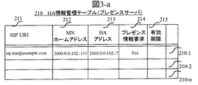
図3-aはHA情報管理テーブル210のテーブル構成の一例を示す。HA情報管理テーブル210は、MNのSIP識別子であるSIP URI211と、少なくてもMNのホームアドレス212、MNのHAアドレス213、プレゼンス情報要求有無214との対応関係を格納する。例えば、エントリ210-1には、SIP URI (sip:mn@example.com)とホームアドレス(2000:0:0:102::111)とHAアドレス(2000:0:0:102::7)とプレゼンス情報要求有無との対応関係が格納される。
上記HA情報管理テーブル210は、プレゼンス情報要求の有効期間を示す有効期限215を含んでもよい。HA情報管理テーブル210が有効期限215を含む場合、プレゼンスサーバ1は、上記プレゼンス情報要求期限を指定できる。また、プレゼンスサーバ1がSIP以外のプロトコルに従う場合は、HA情報管理テーブル210に少なくともMNのホームアドレス212と、MNのHAアドレス213との対応関係が格納されている。
FIG. 3-a shows an example of the table configuration of the HA information management table 210. FIG. The HA information management table 210 stores a correspondence relationship between the
The HA information management table 210 may include an
図3-bはMN情報管理テーブル220のテーブル構成の一例を示す。MN情報管理テーブル220は、MNのSIP識別子であるSIP URI221と、少なくてもMNのホームアドレス222とMNの気付アドレス223との対応関係を格納する。例えば、エントリ220-1には、SIP URI (sip:mn@example.com)とホームアドレス(2000:0:0:102::111)と気付アドレス(3000:300:1:2::100)との対応関係が格納される。
上記MN情報管理テーブル220は、MNのバインディング情報の有効期限224を含んでもよい。MN情報管理テーブル220が有効期限224を含む場合、プレゼンスサーバ1は、有効期限を過ぎたMNのエントリを削除できる。また、プレゼンスサーバ1がSIP以外のプロトコルに従う場合は、MN情報管理テーブル220には少なくともMNのホームアドレス222と、MNの気付アドレス223との対応関係が格納されている。
FIG. 3-b shows an example of a table configuration of the MN information management table 220. The MN information management table 220 stores a correspondence relationship between the
The MN information management table 220 may include an
図3-cはパーミッション情報管理テーブル240のテーブル構成の一例を示す。パーミッション情報管理テーブル240は、MNのSIP識別子であるSIP URI241と、少なくてもプレゼンス情報要求元242とパーミッション243との対応関係を格納する。プレゼンス情報要求元242は、プレゼンス情報要求元のIPアドレス、あるいは、IPアドレスのプレフィックス、あるいは、SIP URI等で指定する。例えば、エントリ240-1には、SIP URI (sip:mn@example.com)とプレゼンス情報要求元(2000:0:0:102::/64)とパーミッション(許可)との対応関係が格納される。
FIG. 3-c shows an example of the table configuration of the permission information management table 240. The permission information management table 240 stores a correspondence relationship between the
図4はHA2の構成例を示す。HA2は、回線22(22a、22b)を収容するインタフェース部(IF)21(21a、21b)と、CPU24と、メモリ25と、データベース26とから構成される。各構成要素は、バス23で接続される。
FIG. 4 shows a configuration example of HA2. The
メモリ25は、SIP処理27を実行するプログラムとMobile IP処理28を実行するプログラムが記憶されている。SIP処理27は、SIPメッセージを送信または受信する機能を備える。SIP処理27は、Binding情報通知先プレゼンスサーバ管理テーブル320を含む。Mobile IP処理28は、Mobile IPメッセージを送信または受信する機能と、Mobile IPのホームエージェント機能を備える。Mobile IP処理28は、Binding Cache管理テーブル310を含む。
データベース26がBinding Cache管理テーブル310とBinding情報通知先プレゼンスサーバ管理テーブル320を含んでもよい。
The
The database 26 may include a Binding Cache management table 310 and a Binding information notification destination presence server management table 320.
図5-aはBinding Cache管理テーブル310のテーブル構成の一例を示す。Binding Cache管理テーブル310は、MNのホームアドレス311と、少なくてもMNが在圏網で取得したCare of Address (CoA)312との対応関係を格納する。例えば、エントリ310-1には、ホームアドレス(2000:0:0:102::111)と気付アドレス(3000:300:1:2::100)との対応関係が格納される。
上記Binding Cache管理テーブル310は、Binding Cacheの有効期間を示すLifetime313を含んでもよい。Binding Cache管理テーブル310がLifetime313を含む場合、HA1は上記テーブルから有効期限が切れたエントリを削除できる。
FIG. 5-a shows an example of the table configuration of the Binding Cache management table 310. FIG. The Binding Cache management table 310 stores a correspondence relationship between the
The Binding Cache management table 310 may include a
図5-bはBinding情報通知先プレゼンスサーバ管理テーブル320のテーブル構成の一例を示す。Binding情報通知先プレゼンスサーバ管理テーブル320は、MNのSIP識別子であるSIP URI321と、少なくともMNのホームアドレス322、プレゼンスサーバのアドレス324との対応関係を格納する。例えば、エントリ320-1には、SIP URI (sip:mn@example.com)とホームアドレス(2000:0:0:102::111)とプレゼンスサーバアドレス(2000:0:0:102::10)との対応関係が格納される。
FIG. 5-b shows an example of the table configuration of the Binding information notification destination presence server management table 320. The binding information notification destination presence server management table 320 stores a correspondence relationship between the
さらに、プレゼンスサービスに加入しているか否かを示すプレゼンスサービス加入有無323、プレゼンス情報取得要求受信有無325との対応関係を格納してもよい。上記Binding情報通知先プレゼンスサーバ管理テーブル320は、プレゼンス情報通知期間を示すタイマ326を含んでもよい。上記Binding情報通知先プレゼンスサーバ管理テーブル320がタイマ326を含む場合、プレゼンス情報取得要求に対して有効期限を設定できる。また、HA2がSIP以外のプロトコルに従う場合は、Binding情報通知先プレゼンスサーバ管理テーブル320に少なくともMNのホームアドレス322と、プレゼンスサーバのアドレス324の対応関係が格納されている。
Furthermore, a correspondence relationship between presence service subscription presence /
図6は情報配信サーバ3の構成例を示す。情報配信サーバは、回線32(32a、32b)を収容するインタフェース部(IF)31(31a、31b)と、CPU34と、メモリ35と、データベース36とから構成される。各構成要素は、バス33で接続される。
メモリ35は、SIP処理37を実行するプログラムとプレゼンス情報処理38を実行するプログラムとを備える。SIP処理37は、SIPメッセージを送信または受信する機能を備える。プレゼンス情報処理38は、端末のプレゼンス情報を送信または受信する機能を備える。プレゼンス情報処理38は、MN情報管理テーブル250と配信情報管理テーブル260とを含む。データベース36がMN情報管理テーブル250と配信情報管理テーブル260を含んでもよい。
FIG. 6 shows a configuration example of the
The
図7-aはMN情報管理テーブル250のテーブル構成の一例を示す。MN情報管理テーブル250は、MNのSIP識別子であるSIP URI251と、少なくてもMNのホームアドレス252と、MNが在圏網で取得したCare of Address (CoA)253との対応関係を格納する。例えば、エントリ250-1には、SIP URI (sip:mn@example.com)とホームアドレス(2000:0:0:102::111)と気付アドレス(3000:300:1:2::100)との対応関係が格納される。
上記MN情報管理テーブル250は、有効期限254を含んでもよい。MN情報管理テーブル250が有効期限254を含む場合、情報配信サーバ3は上記テーブルから有効期限が切れたエントリを削除できる。また、情報配信サーバ3がSIP以外のプロトコルに従う場合は、MN情報管理テーブル250に少なくともMNのホームアドレス252と、MNが在圏網で取得したCare of Address (CoA)253との対応関係が格納されている。
FIG. 7-a shows an example of the table configuration of the MN information management table 250. The MN information management table 250 stores the correspondence relationship between the
The MN information management table 250 may include an
図7-bは配信情報管理テーブル260のテーブル構成の一例を示す。配信情報管理テーブル260は、少なくともMNの気付アドレス261と、配信情報263との対応関係を格納する。
MNの気付アドレス261として、気付アドレスのプレフィックスを設定してもよい。例えば、エントリ260-1には、気付アドレス(3000:300:1:2::/64)と配信情報(α)の対応関係が格納される。さらに、配信情報管理テーブル260は、位置情報262が格納されていてもよい。
FIG. 7B shows an example of the table configuration of the distribution information management table 260. The distribution information management table 260 stores a correspondence relationship between at least the care-of
A prefix of the care-of address may be set as the care-of
次に、IPv6パケットフォーマットについて説明する。IPv6パケットは、IPv6基本ヘッダと、これに続く拡張ヘッダと、これらのヘッダに続くペイロードとから構成される。このIPv6基本ヘッダは、送信元アドレスと、着信先アドレスとを含む。以下、このフォーマットに準拠したIPv6パケットを用いて説明をするが、本発明の効果が発揮される限り、IPv6以外のプロトコルに準拠した、例えばIPv4などのパケットを用いてもよい。 Next, the IPv6 packet format will be described. An IPv6 packet is composed of an IPv6 basic header, an extension header following this, and a payload following these headers. This IPv6 basic header includes a source address and a destination address. Hereinafter, an IPv6 packet conforming to this format will be described. However, as long as the effect of the present invention is exhibited, a packet conforming to a protocol other than IPv6, such as IPv4, may be used.
次に、SIPメッセージを含むパケットフォーマットについて説明する。SIPメッセージは、TCP/UDPなどのトランスポートプロトコルのデータ部に格納される。トランスポートプロトコルのヘッダとデータ部は、IPv6パケットフォーマットのペイロードに格納される。以下このフォーマットに準拠したSIPメッセージを用いて説明するが、本発明の効果が発揮される限り、SIP以外のプロトコルに準拠したメッセージを用いてもよい。 Next, a packet format including a SIP message will be described. The SIP message is stored in the data part of a transport protocol such as TCP / UDP. The header and data part of the transport protocol are stored in the payload of the IPv6 packet format. Hereinafter, description will be made using a SIP message conforming to this format, but a message conforming to a protocol other than SIP may be used as long as the effect of the present invention is exhibited.
図8は、SIPメッセージのフォーマット例S1を示す。
SIPメッセージは、少なくても要求又は応答を示すstart-line 433と、SIPメッセージのパラメータが設定されるmessage-header434とで構成される。SIPメッセージを用いて端末間通信に利用するメディア情報等やプレゼンス情報を送信する場合、SIPメッセージはこれらの情報を格納するmessage-body 435を含む。
FIG. 8 shows a format example S1 of the SIP message.
The SIP message includes at least a start-
次に、Binding Updateメッセージのフォーマットについて説明する。Binding Updateメッセージは、Destination Options HeaderとIPv6 Mobility Headerから構成される。これらのヘッダは、IPv6パケットの拡張ヘッダに格納される。MN7がHA2に送信するBinding Updateには、以下の値が格納される。IPv6パケットヘッダの着信先アドレスに、HA2のアドレスを設定する。IPv6パケットヘッダの送信元アドレスに、MN7が在圏網6で取得した気付アドレスを格納する。送信元アドレスにMN7のホームアドレス以外の値を格納する場合、MN7のホームアドレスがDestination Options HeaderのHome Addressフィールドに格納される。
Next, the format of the Binding Update message will be described. The Binding Update message is composed of a Destination Options Header and an IPv6 Mobility Header. These headers are stored in the extension header of the IPv6 packet. The following values are stored in the Binding Update that MN7 sends to HA2. Set the HA2 address as the destination address in the IPv6 packet header. The care-of address acquired by the
図14と図15に示すシーケンスに従って、図1に示す網6bに在圏するMN7がHA2に位置登録を行い、プレゼンスサービスを利用したパケットを受信するシーケンスを説明する。まず、図14を用いて、プレゼンスサーバ1がHA2からMN7の位置登録情報を取得する手順を説明する。
第1の実施例において、HA2は、気付アドレス通知ルーチン60を備える。プレゼンスサーバ1は、気付アドレス取得ルーチン50を備える。
プレゼンスサーバ1内のHA情報管理テーブル210には、「SIP URI」に対して少なくても「ホームアドレス」と「HAアドレス」が設定されているものとする。
A sequence in which the
In the first embodiment, the
In the HA information management table 210 in the
MN7は在圏網6bに属するルータ5bからルータ広告(Router Avertisement)を受信して(101)、CoAを取得する(102)。在圏網6bでCoA(3000:300:1:2::100)を取得したMN7は、HA2に位置登録メッセージ(Binding Update)を送信する(103)。上記Binding Updateには、以下の値が格納される。MN7のCoAがIPv6パケットヘッダの送信元アドレスに設定される。MN7のホームアドレス(2000:0:0:102::111)がIPv6 Destination Options HeaderのHome Addresフィールドに設定される。
The
HA2のMobile IP処理28では、上記Binding Updateを受信し、 MN7の位置登録処理を行う(104)。Mobile IP処理28では、MN7のホームアドレスを検索キーとして、Binding Cache管理テーブル310を検索する。上記Binding Cache管理テーブル310にMN7のエントリが存在しなければ、上記Binding Cache管理テーブル310にMN7のエントリを追加する。上記エントリのCare of Address312には、MN7が在圏網6bで取得したCoAを設定する。
位置登録終了後、HA2のMobile IP処理28では、Binding Updateの応答(Binding Acknowledgement)をMN7へ送信する(105)。HA2は、MN7のプロキシとして動作する。
The HA2
After the location registration is completed, the HA2
MN7は、正常終了を示すBinding Acknowledgement(105)を受信すると、SIPサーバ4に対するSIP位置登録を開始する。
MN7は、HA2を経由して、SIPサーバ4にSIP位置登録要求メッセージ(REGISTER)(106)を送信する。上記REGISTERメッセージ106を含むオリジナルIPパケットは、HA2宛の着信先アドレスをもつIPv6ヘッダでカプセル化した形でHA2に送信される(106)。HA2は、受信パケットからカプセル化IPv6ヘッダを削除(デカプセル化)し、オリジナルIPパケットをSIPサーバ4に転送する。
When the
The
図14に戻って、SIPサーバ4は、上記SIP位置登録要求メッセージ(REGISTER)を受信すると、SIPの位置登録を行う。具体的には、MNのSIP URI(例:sip:mn@example.com)とホームアドレス(例:2000:0:0:102::111)の対応情報を保持する(107)。SIPサーバ4は、上記SIP位置登録が終わると、MN7に上記SIP位置登録要求に対する応答メッセージ(“200 OK”)を送信する(108)。
SIP位置登録要求メッセージ(106)がHA2を経由していた場合、上記応答メッセージは、HA2経由でMN7に転送される。この場合、SIPサーバ4が送信した応答メッセージを含むIPパケットは、HA2でCoAを宛先アドレスとするIPヘッダでカプセル化され、MN7に転送される(108)。
Returning to FIG. 14, when the SIP server 4 receives the SIP location registration request message (REGISTER), it performs SIP location registration. Specifically, correspondence information between the SIP URI of the MN (example: sip: mn@example.com) and the home address (example: 2000: 0: 0: 102 :: 111) is held (107). When the SIP location registration is completed, the SIP server 4 transmits a response message (“200 OK”) to the SIP location registration request to the MN 7 (108).
When the SIP location registration request message (106) passes through HA2, the response message is transferred to
上述したHA2への位置登録とSIPサーバ4への位置登録は、MN7が同一在圏網に留まっている場合でも、HA2が管理するBinding Cache管理テーブル310とSIPサーバ4が管理するSIP位置登録情報のエントリ有効期限を更新する目的で、所定の周期で繰り返して実行される。HA2への位置登録周期とSIPサーバ4への位置登録周期は必ずしも一致しない。
The location registration to the above-mentioned HA2 and the location registration to the SIP server 4 can be performed by the binding cache management table 310 managed by the HA2 and the SIP location registration information managed by the SIP server 4 even when the
次に、プレゼンスサーバ1が、HA2からMN7の情報を収集する手順を示す。
プレゼンスサーバ1は、プレゼンス情報処理18内に気付アドレス取得ルーチン50を備える。プレゼンスサーバ1は、MN7の気付アドレスを収集するため、気付アドレス取得ルーチン50を起動する。まず、MN7 のSIP URIを検索キーとして、HA情報管理テーブル210を検索する。上記HA情報管理テーブル210にMN7のエントリが存在すれば、上記HA情報管理テーブル210からMN7のHAアドレスを取得する。プレゼンスサーバ1は、MN7のHAアドレスとしてHA2のアドレス(2000:0:0:102::7)を取得して、HA2にSIP SUBSCRIBEメッセージを送信する(51、109)。上記SIP SUBSCRIBEメッセージには、MN7のSIP URI(mn@example.com)と、プレゼンスサーバ1のアドレス(2000:0:0:102:10)と、有効期間が設定される。その後、プレゼンスサーバ1は、上記SUBSCRIBEメッセージに対する応答を待つ(52)。応答待ちの間にSUBSCRIBEの有効期間が満了した場合、プレゼンスサーバ1は本ルーチンを終了する。
Next, a procedure in which the
The
ステップ51において、上記HA情報管理テーブル210に該当エントリが存在しない場合、プレゼンスサーバ1は本ルーチンを終了する。
HA2のSIP処理27では、SUBSCRIBEメッセージ(109)を受信すると、 MN7 のSIPURI(mn@example.com)を検索キーとして、Binding情報通知先プレゼンスサーバ管理テーブル320を検索する。上記テーブル320にMN7のエントリが存在すれば、該当エントリのプレゼンスサービス加入有無323を参照する。MN7がプレゼンスサービスに加入している場合、該当エントリからMN7のホームアドレス322(2000:0:0:102::111)を読み出し、該当エントリの情報を更新する(61)。プレゼンスサーバ324のアドレスには、上記SUBSCRIBEメッセージからプレゼンスサーバ1のアドレス(2000:0:0:102:10)を読み出し、設定する。プレゼンス情報取得要求受信有無325には、有を設定する。タイマ326には、上記SUBSCRIBEメッセージの有効期間を設定する。続いて、HA2はプレゼンスサーバ1に対して、正常終了を示すSIP応答メッセージ(200 OK)を送信する(62、110)。
If there is no corresponding entry in the HA information management table 210 at
In the
ステップ61において、テーブル320にMN7のエントリが存在しない場合、あるいは、MN7がプレゼンスサービスに加入していない場合、HA2はプレゼンスサーバ1に対してエラー通知を含むSIP応答を送信し(67)、本ルーチンを終了する。次に、SIP処理27では、ステップ61で読み出したMN7のホームアドレス(2000:0:0:102::111)を検索キーとして、Binidng Cache管理テーブル310を参照する(63)。MN7のエントリが存在する場合、該当エントリからCare of Address312(3000:300:1:2::100)を読み出す。HA2は、MN7のホームアドレスと上記エントリから読み出した気付アドレスをSIP NOTIFYメッセージのメッセージボディ部(435)に設定し、プレゼンスサーバ1へ送信する(64、111)。図8は、SIP NOTIFYメッセージの1例を示す。上記NOTIFYメッセージのメッセージボディ部にBinding Cacheの有効期限を設定してもよい。
In
図9に戻って、プレゼンスサーバ1は、SIP NOTIFYメッセージを受信し(53)、SIPメッセージの検証を行う(54)。具体的には、上記SIP NOTIFYメッセージがステップ51で送信したSIP SUBSCRIBEメッセージに対応するメッセージであるか検証する。検証の結果がOKであれば、プレゼンスサーバ1はHA2に正常終了を示すSIP応答メッセージ(200 OK)を送信する(55、112)。検証の結果がNGであれば、プレゼンスサーバ1はHA2にエラー通知を示すSIP応答メッセージを送信し(57)、本ルーチンを終了する。
Returning to FIG. 9, the
続いて、プレゼンスサーバ1は、MN7のSIP URI(sip:mn@example.com)を検索キーにして、MN情報管理テーブル220を参照する。該当するエントリが存在しなければ、MN7用の新規エントリを作成し、MN7のホームアドレス(2000:0:0:102::111)と気付アドレス(3000:300:1:2::100)を設定する。該当するエントリが存在する場合、プレゼンスサーバ1は該当エントリのMNホームアドレス222とMN気付アドレス223を更新する。MN7のホームアドレスと気付アドレスは、SIP NOTIFYメッセージのメッセージボディ部からを読み出す(56、113)。さらに、SIP NOTIFYメッセージがMN7のBinding Cacheの有効期限を含む場合、プレゼンスサーバ1は該当するエントリの有効期限(224)を読み出し、上記テーブルに設定する。この後、ステップ52に戻り、SIP SUBSCRIBEの有効期間が満了するまでステップ52からステップ56の処理を繰り返す。
Subsequently, the
図10に戻って、HA2は正常終了を示すSIP応答メッセージ(200 OK)を受信(65)すると、MN7のSIP URI(sip:mn@example.com)を検索キーにして、Binding情報通知先プレゼンスサーバ管理テーブル320を検索する。該当エントリのタイマ326が満了していなければ、ステップ63に戻る。ステップ66において該当エントリのタイマ326が満了している場合、或いは、ステップ65においてHA2がエラー通知を示すSIP応答メッセージを受信した場合、HA2は本ルーチンを終了する。
Returning to FIG. 10, when HA2 receives the SIP response message (200 OK) indicating normal termination (65), the presence of the binding information notification destination using the SIP URI (sip: mn@example.com) of MN7 as a search key The server management table 320 is searched. If the
以上の処理により、プレゼンスサーバ1はHA2からMN7の位置登録情報を取得する。
続いて、図15に示すシーケンスに従って、情報配信サーバ3がプレゼンスサーバ1の情報を参照して、MN7に対して情報を配信するシーケンスを説明する。情報配信サーバ3は、MN7のプレゼンス情報を要求するため、プレゼンスサーバ1にSIP SUBSCRIBEメッセージを送信する(121、122)。上記SIP SUBSCRIBEメッセージは、MN7のSIP URIと情報配信サーバのIPアドレス、又は、SIP URIを含む。本実施例では、上記SIP SUBSCRIBEメッセージが、情報配信サーバ3のIPアドレス(2000:0:0:102::8)を含むとする。
Through the above processing, the
Next, the sequence in which the
SIP SUBSCRIBEメッセージを受信したプレゼンスサーバ1は、上記MN7のSIP URI(sip:mn@example.com)を検索キーとして、パーミッション情報管理テーブル240を参照する。該当するエントリが存在する場合、プレゼンスサーバ1は該当エントリのプレゼンス情報要求元とパーミッションを読み出す。プレゼンスサーバ1は、情報配信サーバ3(2000:0:0:102::108)にMN7(sip:mn@example.com)のプレゼンス情報の通知を許可する。そこで,プレゼンスサーバ1は、情報配信サーバ3へ応答メッセージ(200 OK)を送信する(123)。続いて、プレゼンスサーバ1は、MN7のSIP URI(sip:mn@example.com)を検索キーとして、MN情報管理テーブル220を参照する。該当するエントリが存在する場合、プレゼンスサーバ1は該当エントリのMNホームアドレス222(2000:0:0:102::111)とMN気付アドレス223(3000:300:1:2::100)を読み出す。プレゼンスサーバ1は、MN7のホームアドレスと気付アドレスを含むSIP NOTIFYメッセージを情報配信サーバ3へ送信する(124、125)。
The
情報配信サーバ3のプレゼンス情報処理38では、SIP NOTIFYメッセージを受信すると、配信情報決定ルーチン90を起動する。まず、プレゼンス情報処理38では、SIPメッセージを検証する(91)。受信メッセージがステップ121で送信したSIP SUBSCRIBEメッセージに対応するメッセージであれば、情報配信サーバ3は、正常応答を示すSIPメッセージ(200 OK)をプレゼンスサーバ1へ送信する(92、126)。受信メッセージがステップ121で送信したSIP SUBSCRIBEメッセージに対応するメッセージでなければ、情報配信サーバ3は、エラー通知を示すSIPメッセージをプレゼンスサーバ1へ送信し(96)、本ルーチンを終了する。
When the
次に、情報配信サーバ3のプレゼンス情報処理38では、MN7のSIP URI(sip:mn@example.com)を検索キーとして、MN情報管理テーブル250を検索する。該当するエントリがあれば、情報配信サーバ3は、ステップ124で受信したSIP NOTIFYメッセージからMN7のホームアドレスと気付アドレスを読み出し、それぞれMNホームアドレス252(2000:0:0:102::111)とMN気付アドレス253(3000:300:1:2::100)に設定する(93)。上記SIP NOTIFYメッセージがBinding Cacheの有効期限を含む場合、上記テーブル250の有効期限254に値を設定する。該当するエントリがなければ、MN7の新規エントリを作成する。
Next, the
続いて、情報配信サーバ3は、気付アドレスに対応した配信情報を決定するため、ステップ93でMN情報管理テーブル250に格納したMN7の気付アドレス、あるいは気付アドレスのプレフィックス(3000:300:1:2::/64)を検索キーとして、配信情報管理テーブル260を検索する(94)。該当するエントリが存在すれば、配信情報263(α)を読み出す。次に、情報配信サーバ3はMN7との間にセッションを確立し、情報を配信する。情報配信サーバ3とMN7の間のセッション確立手段として、たとえばSIPを用いる。情報配信サーバ3がMN7に対してセッション確立要求を送信する(SIP INVITE)(127、128)。上記セッション確立要求は、SIPサーバ4によってMN7へ転送される。上記SIP INVITEを受信したMN7は、セッションの確立要求を受け付ける場合、正常応答を示すSIPメッセージ(200 OK)をSIPサーバ経由で情報配信サーバ3へ送信する(129、130)。情報配信サーバ3は、上記SIPメッセージに対する応答確認メッセージ(131、132)をMN7へ送信する。以上のステップで、情報配信サーバ3とMN7の間にセッションが確立される。続いて、情報配信サーバ3は、ステップ94で取得した情報(α)をMN7へ送信し(95、134)、本ルーチンを終了する。
ステップ94において、該当するエントリが存在しなければ、情報配信サーバ3は本ルーチンを終了する。
Subsequently, the
If there is no corresponding entry in
本発明の第1の実施の形態によると、プレゼンスサーバがHAからMNの位置登録情報を取得する手段を備えることにより、ホーム網以外に存在するMNに対して、プレゼンスサービスの提供が可能になる。特に、MNの位置情報はプレゼンスサーバがHAから取得するため、ホーム網以外に存在するMNが任意の通信相手に対してバインディング情報を送信する必要がなくなり、セキュリティを保つことが可能になる。 According to the first embodiment of the present invention, since the presence server includes means for acquiring location registration information of the MN from the HA, it is possible to provide a presence service to the MN that exists outside the home network. . In particular, since the presence server obtains the location information of the MN from the HA, it is not necessary for the MN existing outside the home network to transmit the binding information to any communication partner, and security can be maintained.
本発明の第2の実施の形態を図面を用いて説明する。第2の実施例は、HA2がモバイルIPの位置登録メッセージの受信を契機に、プレゼンスサーバ1にMNのバインディング情報を通知する手段を備えることを特徴とする。
第2の実施例において、HA2は、気付アドレス通知ルーチン60の代わりに気付アドレス取得ルーチン70を備える。プレゼンスサーバ1は、気付アドレス取得ルーチン50の代わりに、気付アドレス取得ルーチン80を備える。
A second embodiment of the present invention will be described with reference to the drawings. The second embodiment is characterized by comprising means for notifying the
In the second embodiment, the
第2の実施例において、Binding情報通知先プレゼンスサーバ管理テーブル320には、「SIP URI」に対して少なくても「ホームアドレス」と「プレゼンスサーバアドレス」が設定されているものとする。
図16に示すシーケンスに従って、HA2がプレゼンスサーバ1へMN7の位置登録情報を通知する手順を説明する。
MN7が在圏網でCoAを取得し、HA2へ位置登録を行うまでの処理(ステップ101からステップ105)は、第1の実施例と同じである。
In the second embodiment, it is assumed that at least a “home address” and a “presence server address” are set for “SIP URI” in the binding information notification destination presence server management table 320.
A procedure in which the
The processing (from step 101 to step 105) from when the
HA2のMobile IP処理28では、MNの位置登録が完了すると、気付アドレス通知ルーチン70を起動する。HA2は、ステップ103で受信したMN7のホームアドレス(2000:0:0:102::111)を検索キーとして、Binding情報通知先プレゼンスサーバ管理テーブル320を参照する。該当エントリが存在する場合、Mobile IP処理28ではMN7のSIP URI321(sip:mn@example.com)と、プレゼンスサーバのアドレス324(2000:0:0:102::10)を抽出する(71)。ステップ71において該当エントリがない場合、HA2は本ルーチンを終了する。
In the
HA2は、ステップ71で取得したプレゼンスサーバ1に対して、ステップ103で受信したMN7 のバインディング情報を通知する。バインディング情報の通知には、SIP REGISTERメッセージを用いる(72、141)。上記SIP REGISTERメッセージ(141)は、ステップ71で読み出したMN7のSIP URIと、ステップ103で受信したバインディング情報を含む。上記バインディング情報は、少なくてもMN7のホームアドレスと気付アドレスを含む。
HA2 notifies the
プレゼンスサーバ1のプレゼンス情報処理18では、SIP REGISTERメッセージを受信すると、気付アドレス取得ルーチン80を起動する。まず、プレゼンス情報処理18は、受信したSIPメッセージを検証する(81)。プレゼンスサーバ1がSIPメッセージを許容する場合、SIP REGISTERメッセージ141に含まれるMN7のSIP URI(sip:mn@example.com)を検索キーとして、MN情報管理テーブル220を参照する。該当エントリがあれば、プレゼンスサーバ1は、該当エントリのMNホームアドレス222(2000:0:0:102::111)とMN気付アドレス223 (3000:300:1:2::100)を更新する。MN7のホームアドレスと気付アドレスは、上記SIP REGISTERメッセージ(141)から読み出す(82、 142)。該当エントリがなければ、新規エントリを生成する。その後、プレゼンスサーバ1はHA2へ正常応答を含むSIPメッセージ(200 OK)を送信し (83、143)、本ルーチンを終了する。
When the
ステップ81において、SIPメッセージを許容しない場合、プレゼンスサーバ1は、HAへエラー通知を含む応答メッセージを送信し、本ルーチンを終了する。
MN7がSIPサーバ4へSIP位置登録を行う手順(ステップ106からステップ108)は、第1の実施例と同じである。
情報配信サーバ3がプレゼンスサーバ1の情報を参照して、MN7に対して情報を配信する手順は、第1の実施例と同じである。
In
The procedure (step 106 to step 108) in which the
The procedure in which the
本発明の第2の実施の形態によると、プレゼンスサーバがHAに対するプレゼンス情報要求機能を備えない場合であっても、プレゼンスサーバはMNのバインディング情報を取得できる。特に、 HAがプレゼンスサーバにMNの位置情報を通知するため、ホーム網以外に存在するMNは直接任意の通信相手に対してバインディング情報を送信する必要がなくなり、セキュリティを保つことが可能になる。 According to the second embodiment of the present invention, even when the presence server does not have a presence information request function for the HA, the presence server can acquire the binding information of the MN. In particular, since the HA notifies the presence server of the location information of the MN, the MN existing outside the home network does not need to send binding information directly to any communication partner, and security can be maintained.
本発明の第3の実施の形態を図面を用いて説明する。
第3の実施例は、第1の実施例、第2の実施例における情報配信サービスのかわりに、プレゼンスサーバ1がバインディング情報を発着信制御に適用する手段を備えることを特徴とする。
A third embodiment of the present invention will be described with reference to the drawings.
The third embodiment is characterized in that, instead of the information distribution service in the first and second embodiments, the
図17は、本発明の第3の実施の形態における通信網の構成例を示す。図17では端末30がホーム網10に接続される例を示すが、端末30はホーム網10以外に接続されてもよい。
第3の実施例において、プレゼンスサーバ1は、発着信情報管理テーブル230を備えることを特徴とする。
FIG. 17 shows a configuration example of a communication network according to the third embodiment of the present invention. Although FIG. 17 shows an example in which the terminal 30 is connected to the
In the third embodiment, the
図18は発着信情報管理テーブル230のテーブル構成の一例を示す。発着信情報管理テーブル230は、MNの気付アドレス231に対して、発信可否情報232と着信可否情報233の対応関係を格納する。MNの気付アドレス231として、気付アドレスのプレフィックス(例:3000:300:1:2::/64)を設定してもよい。
FIG. 18 shows an example of the table configuration of the outgoing / incoming call information management table 230. The outgoing / incoming call information management table 230 stores the correspondence between the outgoing /
図19に示すシーケンスに従って、図17に示す端末30が網6bに在圏するMN7に発信する際の制御手順を説明する。
プレゼンスサーバ1がMN7のバインディング情報を取得する方法は、第1の実施例、又は、第2の実施例と同じである。
ホーム網10に存在する端末30が、MN7に対してセッション確立を要求する(SIP INVITE)(151)。上記SIP INVITEはMN7のSIP URI(sip:mn@example.com)を含む。上記SIP INVITEを受信したSIPサーバ4は、プレゼンスサーバ1にMN7のプレゼンス情報を問い合わせる(152)。上記問い合わせ152には、MN7のSIP URIが含まれる。プレゼンスサーバ1は、上記問い合わせ152を受信すると、MN7のSIP URI(sip:mn@example.com)を検索キーとして、MN情報管理テーブル220を参照する。該当エントリが存在する場合、該当エントリからMN7の気付アドレス223(3000:300:1:2::100)を読み出す。次に、プレゼンスサーバ1は、MN7の気付アドレス、あるいは、MN7の気付アドレスのプレフィックスを検索キーとして、発着信情報管理テーブル230を参照する。該当エントリが存在する場合、プレゼンスサーバ1は、該当エントリの発信可否情報(232)と着信拒否情報(233)を読み出す。ここで、MN7の気付アドレスのプレフィックス(3000:300:1:2::/64)に対して、”着信拒否”が設定されているとする。着信拒否が設定されている場合、プレゼンスサーバ1は、SIPサーバ4へ着信拒否を含む応答メッセージ153を送信する。上記メッセージ153を受信したSIPサーバ4は、セッション確立要求(151)の応答として、エラー通知を含むSIP応答メッセージ(例えば、受け入れ不能を示す606 NOT Acceptable)を通信相手端末に送信する(154)。通信相手端末は、上記メッセージ154の応答確認をSIPサーバ4へ送信する(155)。
A control procedure when the terminal 30 shown in FIG. 17 transmits to the
The method for the
The terminal 30 existing in the
本発明の第3の実施の形態によると、プレゼンスサーバがMNのバインディング情報を取得する手段と、気付アドレス、または、気付アドレスのプレフィックスに対応する発着信制御情報を備えることにより、MNの在圏アドレスに応じた発着信制御サービスの提供が可能になる。 According to the third embodiment of the present invention, the presence server includes means for acquiring the binding information of the MN, and the outgoing / incoming control information corresponding to the care-of address or the prefix of the care-of address, thereby It is possible to provide an outgoing / incoming control service according to an address.
本発明の第4の実施の形態を図面を用いて説明する。
図20は、本発明の第4の実施の形態における通信網の構成例を示す。図20ではプレゼンスサーバ1がSIPサーバ4に接続される例を示す。中継網がプレゼンスサーバ1とSIPサーバ4の間に存在してもよい。
A fourth embodiment of the present invention will be described with reference to the drawings.
FIG. 20 shows a configuration example of a communication network in the fourth embodiment of the present invention. FIG. 20 shows an example in which the
第4の実施例は、SIPサーバ4がHA2とプレゼンスサーバ1の間のメッセージを中継する際、SIPサーバ4がMNのバインディング情報を格納する手段を備えることを特徴とする。
図21はSIPサーバ4の構成例を示す。SIPサーバ4は、回線42(42a、42b)を収容するインタフェース部(IF)41(41a、41b)と、CPU44と、メモリ45と、データベース46とから構成される。各構成要素は、バス43で接続される。
The fourth embodiment is characterized in that when the SIP server 4 relays a message between the
FIG. 21 shows a configuration example of the SIP server 4. The SIP server 4 includes an interface unit (IF) 41 (41a, 41b) that accommodates the line 42 (42a, 42b), a
第4の実施例において、メモリ45には、SIP処理47を実行するプログラムとBinding情報処理48を実行するプログラムが記憶されている。SIP処理47は、SIPメッセージを送信または受信する機能と、発着信制御機能を備える。SIP処理47は、図18に示す発着信情報管理テーブル230を含む。Binding情報処理48は、端末のbinding情報を管理する機能を備える。Binding情報処理48は、MN情報管理テーブル330を含む。データベース46が、MN情報管理テーブル330と発着信情報管理テーブルを含んでもよい。
In the fourth embodiment, the
図22はMN情報管理テーブル330のテーブル構成の一例を示す。MN情報管理テーブル330は、MNのSIP識別子であるSIP URI331と、少なくてもMNのホームアドレス332とMNの気付アドレス333との対応関係を格納する。例えば、エントリ330-1には、SIP URI (sip:mn@example.com)とホームアドレス(2000:0:0:102::111)と気付アドレス(3000:300:1:2::100)との対応関係が格納される。
上記MN情報管理テーブル330は、MNのバインディング情報の有効期限334を含んでもよい。MN情報管理テーブル330が有効期限334を含む場合、SIPサーバ4は、有効期限を過ぎたMNのエントリを削除できる。
FIG. 22 shows an example of a table configuration of the MN information management table 330. The MN information management table 330 stores a correspondence relationship between the
The MN information management table 330 may include an
図23に示すシーケンスに従って、SIPサーバ4がHA2とプレゼンスサーバ1の間のメッセージを中継するとき、上記メッセージを参照する手順を説明する。HA2がモバイルIPの位置登録メッセージの受信を契機にプレゼンスサーバ1にMNのバインディング情報を通知する手段を備える場合について説明する。
MN7が在圏網でCoAを取得し、HA2へ位置登録を行うまでの処理(ステップ101からステップ105)は、第1の実施例及び第2の実施例と同じである。
A procedure for referring to the message when the SIP server 4 relays a message between the
The processing (from step 101 to step 105) from when the
HA2は、MNの位置登録が完了すると、プレゼンスサーバ1に対して、MN7 のバインディング情報を通知する。HA2の処理ステップは、第2の実施例と同じである。バインディング情報の通知には、SIP REGISTERメッセージ(161)を用いる。上記SIP REGISTERメッセージ(161)は、MN7のSIP URIとバインディング情報を含む。上記バインディング情報は、少なくてもMN7のホームアドレスと気付アドレスを含む。
When the location registration of the MN is completed, the
SIPサーバ4は、上記SIP REGISTERメッセージ(161)を中継する。上記SIP REGISTERメッセージがプレゼンスサーバ1宛のメッセージである場合、SIPサーバ4は、上記メッセージを検証する。上記メッセージがMN7のバインディング情報を含む場合、SIPサーバ4はMN7のSIP URI(sip:mn@example.com)を検索キーとして、MN情報管理テーブル330を参照する。該当エントリがあれば、SIPサーバ4は、該当エントリにMNホームアドレス332(2000:0:0:102::111)とMN気付アドレス333 (3000:300:1:2::100)を仮登録する(162)。MN7のホームアドレスと気付アドレスは、上記SIP REGISTERメッセージ(161)から読み出す。該当エントリがなければ、新規エントリを生成する。その後、SIPサーバ4はプレゼンスサーバ1にSIP REGISTERメッセージを送信する(163)。
The SIP server 4 relays the SIP REGISTER message (161). If the SIP REGISTER message is a message addressed to the
プレゼンスサーバ1は、上記SIP REGISTERメッセージを受信すると、第2の実施例と同様にMNのバインディング情報を格納し、SIP応答メッセージを送信する(164、 165)。
上記SIP応答メッセージが正常応答を示し、かつ、ステップ163で送信したSIP REGISTERに対応するメッセージである場合、SIPサーバ4はステップ162で仮登録したエントリを正式に登録する(166)。その後、SIPサーバ4は、HA2にSIP応答メッセージを送信する(167)。
MN7がSIPサーバ4へSIP位置登録を行う手順(ステップ106からステップ108)は、第1の実施例及び第2の実施例と同じである。
When the
If the SIP response message indicates a normal response and is a message corresponding to the SIP REGISTER transmitted in
The procedure (step 106 to step 108) in which the
次に、端末30が網6bに在圏するMN7に発信する際の制御手順を説明する。
ホーム網10に存在する端末30が、MN7に対してセッション確立を要求する(SIP INVITE)(168)。上記SIP INVITEはMN7のSIP URI(sip:mn@example.com)を含む。上記SIP INVITEを受信したSIPサーバ4は、MN7のSIP URI(sip:mn@example.com)を検索キーとして、MN情報管理テーブル330を参照する。該当エントリが存在する場合、該当エントリからMN7の気付アドレス333(3000:300:1:2::100)を読み出す。次に、SIPサーバ4は、MN7の気付アドレス、あるいは、MN7の気付アドレスのプレフィックスを検索キーとして、発着信情報管理テーブル230を参照する。該当エントリが存在する場合、SIPサーバ4は、該当エントリの発信可否情報(232)と着信拒否情報(233)を読み出す。ここで、MN7の気付アドレスのプレフィックス(3000:300:1:2::/64)に対して、”着信拒否”が設定されているとする。着信拒否が設定されている場合、SIPサーバ4は、セッション確立要求(168)の応答として、エラー通知を含むSIP応答メッセージ(例えば、受け入れ不能を示す606 NOT Acceptable)を通信相手端末に送信する(169)。通信相手端末は、上記メッセージ169の応答確認をSIPサーバ4へ送信する(170)。
Next, a control procedure when the terminal 30 transmits to the
The terminal 30 existing in the
本発明の第4の実施の形態によると、SIPサーバがMNのバインディング情報と発着信制御機能を備えることにより、SIPサーバは、プレゼンスサーバに問い合わせることなくMNの在圏アドレスに応じた発着信制御サービスを提供することが可能になる。 According to the fourth embodiment of the present invention, since the SIP server has the MN binding information and the outgoing / incoming call control function, the SIP server can perform outgoing / incoming call control according to the MN's location address without querying the presence server. It becomes possible to provide services.
本発明を用いると、通信装置は、移動先ネットワークにおけるモバイルIP対応移動端末に対して、気付アドレスに応じたサービスの提供が可能になる。本発明は、モバイルIP対応移動端末に対して、気付アドレスに応じた通信サービスを実現する場合に、利用される可能性がある。 By using the present invention, the communication apparatus can provide a service corresponding to the care-of address to the mobile IP compatible mobile terminal in the destination network. The present invention may be used when a communication service corresponding to a care-of address is realized for a mobile terminal supporting mobile IP.
1 Presence Server、 2 HA、 3 情報配信サーバ、4 SIPサーバ、7 Mobile IP移動ノード(MN)、50気付アドレス取得ルーチン、60気付アドレス通知ルーチン、70気付アドレス通知ルーチン、80気付アドレス取得ルーチン、 90配信情報決定ルーチン。 1 Presence Server, 2 HA, 3 Information Distribution Server, 4 SIP Server, 7 Mobile IP Mobile Node (MN), 50 Care of Address Acquisition Routine, 60 Care of Address Notification Routine, 70 Care of Address Notification Routine, 80 Care of Address Acquisition Routine, 90 Delivery information determination routine.
Claims (9)
CPUと、
上記端末の位置情報を格納するメモリと、
上記端末から該端末の位置情報であるMobileIPのバインディング情報のうち、ホームアドレス及び気付きアドレスのいずれか一方を受信し、上記ホームアドレスと上記気付きアドレスとを対応付けて上記プレゼンスサーバへ送信する送受信部と、
を備えることを特徴とする通信装置。 A communication device connected to a terminal and a presence server via a network,
CPU,
A memory for storing location information of the terminal;
A transmission / reception unit that receives one of a home address and a care-of address from the MobileIP binding information that is location information of the terminal from the terminal , and associates the home address with the care-of address and transmits the association to the presence server When,
A communication apparatus comprising:
CPUと、
上記サーバから上記端末のMobileIPのバインディング情報に含まれる気付きアドレスを受信する送受信部と、
受信した上記端末の気付きアドレスを該端末のホームアドレスと対応付けて格納するメモリと、を備えることを特徴とする状態情報管理装置。 A state information management device connected to a terminal and a server for managing MobileIP binding information of the terminal via a network ,
CPU,
A transmission / reception unit that receives a care-of address included in the MobileIP binding information of the terminal from the server;
A state information management apparatus comprising: a memory that stores the received address of the terminal in association with the home address of the terminal.
上記端末位置情報管理サーバは、
上記端末から該端末のMobileIPのバインディング情報に含まれる気付きアドレスを受信し、該気付きアドレスと前記端末のホームアドレスとを対応付けてプレゼンスサーバに送信する送受信部を備え、
上記プレゼンスサーバは、
上記端末の上記端末位置情報管理サーバから該気付きアドレスと前記端末のホームアドレスとを受信し、上記サービス用サーバに該気付きアドレスと前記端末のホームアドレスとを対応付けて送信する送受信部を備え、
上記サービス用サーバは、
上記プレゼンスサーバから該気付きアドレスと前記端末のホームアドレスとを受信し、該気付きアドレスに応じたデータを上記端末に送信する送受信部を備えたことを特徴とする通信システム。 A communication system that is connected to a terminal and includes a terminal location information management server, a presence server, and a service server,
The terminal location information management server
A transmission / reception unit that receives a care-of address included in the MobileIP binding information of the terminal from the terminal, associates the care-of address with the home address of the terminal, and transmits to the presence server;
The presence server
A transmission / reception unit that receives the notice address and the home address of the terminal from the terminal location information management server of the terminal, and transmits the notice address and the terminal home address in association with the service server;
The service server is
Communication system, characterized in that said from the presence server and the gas with address receives the home address of the terminal, the data corresponding to the gas with addresses having a transceiver for transmitting to the terminal.
上記プレゼンスサーバからの情報通知要求を受信し、上記端末の該気付きアドレスと前記端末のホームアドレスとを返信することを特徴とする請求項5記載の通信システム。 The transmission / reception unit of the terminal location information management server
6. The communication system according to claim 5, wherein an information notification request from the presence server is received, and the notice address of the terminal and the home address of the terminal are returned.
上記サービス用サーバから情報参照要求を受信し、上記端末の該気付きアドレスと前記端末のホームアドレスとを返信することを特徴とする請求項5記載の通信システム。 The transmission / reception unit of the presence server
6. The communication system according to claim 5, wherein an information reference request is received from the service server, and the care-of address of the terminal and the home address of the terminal are returned.
CPUと、
上記プレゼンスサーバからMobileIPのバインディング情報に含まれる上記端末の該気付きアドレスと前記端末のホームアドレスとを対応付けた位置情報を受信し、上記位置情報に含まれる前記気付きアドレスに応じたデータを上記端末に送信する送受信部と、
上記端末の位置情報と該位置情報に応じた上記データの対応関係を格納するメモリと、を備えたことを特徴とするサービス用サーバ。 A service server connected to a terminal and a presence server via a network,
CPU,
Receives location information associating the home address of the the said gas with the address of the terminal included in the binding information MobileIP from the presence server terminal, the data corresponding to the notice addresses included in the position information A transmission / reception unit that transmits to the terminal;
A service server comprising: location information of the terminal; and a memory that stores a correspondence relationship between the data corresponding to the location information.
上記端末情報管理装置から上記端末状態情報管理装置に向けて送信された上記端末の気付きアドレスを受信し、該気付きアドレスを上記端末のホームアドレスに対応付けて上記端末状態情報管理装置に送信する送受信部と、
上記気付きアドレスと上記ホームアドレスと上記位置情報とに対応した通信制御情報を格納するメモリと、を備えた通信制御装置。 A communication control device connected to a terminal, a terminal information management device, and a terminal state information management device via a network,
Transmission / reception of receiving the care-of address of the terminal transmitted from the terminal information management device to the terminal state information management device and transmitting the care-of address to the terminal state information management device in association with the home address of the terminal And
And a memory for storing communication control information corresponding to the care-of address, the home address, and the position information.
Priority Applications (3)
| Application Number | Priority Date | Filing Date | Title |
|---|---|---|---|
| JP2004154078A JP4438510B2 (en) | 2004-05-25 | 2004-05-25 | COMMUNICATION SYSTEM AND COMMUNICATION CONTROL DEVICE |
| CN2005100055575A CN1703050B (en) | 2004-05-25 | 2005-01-19 | Communication system and communication control equipment |
| US11/052,247 US8036182B2 (en) | 2004-05-25 | 2005-02-08 | Communication system and communication control equipment |
Applications Claiming Priority (1)
| Application Number | Priority Date | Filing Date | Title |
|---|---|---|---|
| JP2004154078A JP4438510B2 (en) | 2004-05-25 | 2004-05-25 | COMMUNICATION SYSTEM AND COMMUNICATION CONTROL DEVICE |
Publications (3)
| Publication Number | Publication Date |
|---|---|
| JP2005340982A JP2005340982A (en) | 2005-12-08 |
| JP2005340982A5 JP2005340982A5 (en) | 2007-04-19 |
| JP4438510B2 true JP4438510B2 (en) | 2010-03-24 |
Family
ID=35425127
Family Applications (1)
| Application Number | Title | Priority Date | Filing Date |
|---|---|---|---|
| JP2004154078A Expired - Fee Related JP4438510B2 (en) | 2004-05-25 | 2004-05-25 | COMMUNICATION SYSTEM AND COMMUNICATION CONTROL DEVICE |
Country Status (3)
| Country | Link |
|---|---|
| US (1) | US8036182B2 (en) |
| JP (1) | JP4438510B2 (en) |
| CN (1) | CN1703050B (en) |
Families Citing this family (33)
| Publication number | Priority date | Publication date | Assignee | Title |
|---|---|---|---|---|
| US8145908B1 (en) * | 2004-10-29 | 2012-03-27 | Akamai Technologies, Inc. | Web content defacement protection system |
| US7870265B2 (en) * | 2005-06-30 | 2011-01-11 | Oracle International Corporation | System and method for managing communications sessions in a network |
| CN1870658B (en) * | 2005-07-01 | 2010-07-07 | 华为技术有限公司 | User positioning system and method in packet network |
| CN101346634B (en) * | 2005-11-04 | 2012-10-24 | 甲骨文国际公司 | System and method for a gatekeeper in a communications network |
| US7751830B2 (en) * | 2006-02-17 | 2010-07-06 | Cisco Technology, Inc. | Techniques for proving location/presence-based information using mobile IP |
| US8391153B2 (en) | 2006-02-17 | 2013-03-05 | Cisco Technology, Inc. | Decoupling radio resource management from an access gateway |
| CN101496387B (en) | 2006-03-06 | 2012-09-05 | 思科技术公司 | System and method for access authentication in a mobile wireless network |
| EP1841171B1 (en) * | 2006-03-30 | 2010-09-15 | Alcatel Lucent | Connection optimisation between a mobile communication terminal and a signalling server across a Network Address Translator |
| US8112525B2 (en) * | 2006-05-16 | 2012-02-07 | Oracle International Corporation | Engine near cache for reducing latency in a telecommunications environment |
| US8171466B2 (en) | 2006-05-16 | 2012-05-01 | Oracle International Corporation | Hitless application upgrade for SIP server architecture |
| US8001250B2 (en) | 2006-05-16 | 2011-08-16 | Oracle International Corporation | SIP and HTTP convergence in network computing environments |
| US8219697B2 (en) | 2006-05-17 | 2012-07-10 | Oracle International Corporation | Diameter protocol and SH interface support for SIP server architecture |
| JP5061596B2 (en) * | 2006-11-24 | 2012-10-31 | 沖電気工業株式会社 | Presence server, presence system, presence server control method, and presence system control method |
| JP5076491B2 (en) | 2006-12-27 | 2012-11-21 | 富士通株式会社 | Message receiving method, authentication server, mobile network system |
| US8320295B2 (en) | 2007-01-18 | 2012-11-27 | Nec Corporation | Mobile IP control system, mobile IP control method, and mobile IP control program |
| JP4762181B2 (en) * | 2007-03-19 | 2011-08-31 | 株式会社東芝 | SIP trunk gateway device and method for controlling SIP trunk gateway device |
| EP2007111A1 (en) * | 2007-06-22 | 2008-12-24 | France Telecom | Method for filtering packets coming from a communication network |
| US8249934B2 (en) * | 2007-06-27 | 2012-08-21 | Alcatel Lucent | IMS network providing purchasing sessions to mobile devices that are located proximate to a business |
| CN101965722B (en) * | 2008-03-12 | 2013-06-26 | 艾利森电话股份有限公司 | Re-establishment of a security association |
| JP4445559B2 (en) * | 2008-05-30 | 2010-04-07 | 株式会社東芝 | Presence service providing system and its server unit |
| WO2009153943A1 (en) * | 2008-06-16 | 2009-12-23 | パナソニック株式会社 | Binding cache creating method, binding cache creating system, home agent, and mobile node |
| JP5104591B2 (en) * | 2008-06-27 | 2012-12-19 | 富士通株式会社 | Bus system |
| JP2010028286A (en) * | 2008-07-16 | 2010-02-04 | Hitachi Ltd | Sip server and communication system |
| US8681739B1 (en) | 2008-08-06 | 2014-03-25 | Marvell International Ltd. | Method and apparatus for supporting multiple connections over different types of access in 3GPP systems |
| US10512112B1 (en) | 2008-08-06 | 2019-12-17 | Marvell International Ltd. | Method and apparatus for supporting multiple connections over different types of access in 3GPP systems |
| US8179912B2 (en) * | 2008-09-26 | 2012-05-15 | Oracle International Corporation | System and method for providing timer affinity through engine polling within a session-based server deployment |
| US9723048B2 (en) * | 2008-10-29 | 2017-08-01 | Oracle International Corporation | System and method for providing timer affinity through notifications within a session-based server deployment |
| US8275894B2 (en) * | 2009-01-15 | 2012-09-25 | Samsung Electronics Co., Ltd | System and method for providing location information of a terminal |
| JP5147995B2 (en) * | 2009-02-05 | 2013-02-20 | テレフオンアクチーボラゲット エル エム エリクソン(パブル) | Host identity protocol server address configuration |
| EP2449747A1 (en) * | 2009-06-30 | 2012-05-09 | France Telecom | Method and device for acknowledging a periodic signaling request in a telecommunication network |
| US8385285B2 (en) * | 2009-11-20 | 2013-02-26 | Telefonaktiebolaget Lm Ericsson (Publ) | System, method and devices for enabling efficient hybrid route optimization between two mobile endpoints |
| US9565167B2 (en) * | 2015-01-21 | 2017-02-07 | Huawei Technologies Co., Ltd. | Load balancing internet protocol security tunnels |
| US10248365B2 (en) | 2016-12-30 | 2019-04-02 | Konica Minolta Laboratory U.S.A., Inc. | Method and system of using OAuth2 to secure neighbor discovery |
Family Cites Families (8)
| Publication number | Priority date | Publication date | Assignee | Title |
|---|---|---|---|---|
| US6442616B1 (en) * | 1997-01-16 | 2002-08-27 | Kabushiki Kaisha Toshiba | Method and apparatus for communication control of mobil computers in communication network systems using private IP addresses |
| KR100429182B1 (en) * | 1998-09-07 | 2004-06-16 | 엘지전자 주식회사 | Method of Realizing Mobile Communication Packet Data Network in the Non-ATM Backbone Network |
| KR100396643B1 (en) * | 1998-09-07 | 2003-10-17 | 엘지전자 주식회사 | Radio Packet Data Terminal |
| US20040015607A1 (en) * | 2000-01-28 | 2004-01-22 | Bender Paul E. | System and method for using an IP address as a wireless unit identifier |
| US7711819B2 (en) * | 2001-10-31 | 2010-05-04 | Fujitsu Limited | Load balancer |
| JP4349766B2 (en) | 2001-12-07 | 2009-10-21 | 株式会社日立製作所 | Address translation device |
| JP4028793B2 (en) * | 2002-12-03 | 2007-12-26 | 株式会社日立製作所 | Mobile terminal apparatus and inter-terminal packet communication method |
| JP4345368B2 (en) * | 2003-06-17 | 2009-10-14 | 株式会社日立製作所 | Presence management device and information distribution system |
-
2004
- 2004-05-25 JP JP2004154078A patent/JP4438510B2/en not_active Expired - Fee Related
-
2005
- 2005-01-19 CN CN2005100055575A patent/CN1703050B/en not_active Expired - Fee Related
- 2005-02-08 US US11/052,247 patent/US8036182B2/en not_active Expired - Fee Related
Also Published As
| Publication number | Publication date |
|---|---|
| CN1703050A (en) | 2005-11-30 |
| US8036182B2 (en) | 2011-10-11 |
| CN1703050B (en) | 2012-04-25 |
| US20050265276A1 (en) | 2005-12-01 |
| JP2005340982A (en) | 2005-12-08 |
Similar Documents
| Publication | Publication Date | Title |
|---|---|---|
| JP4438510B2 (en) | COMMUNICATION SYSTEM AND COMMUNICATION CONTROL DEVICE | |
| JP4617911B2 (en) | COMMUNICATION DEVICE, COMMUNICATION CONTROL DEVICE, AND COMMUNICATION SYSTEM | |
| JP4431112B2 (en) | Terminal and communication system | |
| JP4028793B2 (en) | Mobile terminal apparatus and inter-terminal packet communication method | |
| KR100605806B1 (en) | A phone-based mobile internet protocol, voice over internet protocol, and session initiation protocol, session initiation protocol server, and routing path control method and system for session initiation protocol service | |
| US7974269B2 (en) | Mobile communication control method and mobile communication system | |
| US7319689B2 (en) | Method for handling the simultaneous mobility of mobile hosts in infrastructure-based networks | |
| JP5199314B2 (en) | Method and apparatus for extending mobile IP | |
| US20040090941A1 (en) | Dynamic re-routing of mobile node support in home servers | |
| US20130188651A1 (en) | Mobility in ip without mobile ip | |
| JP2004153392A (en) | Communication system | |
| EP1634424B1 (en) | Methods and apparatuses for optimizing resource management in cdma2000 wireless ip networks | |
| JP3601464B2 (en) | Mobile terminal management system, mobile terminal management method and terminal in mobile network | |
| JP4591263B2 (en) | Communication control device and communication system | |
| JP2004312517A (en) | Path optimization system, method, and program | |
| JP4823053B2 (en) | Method for switching between different types of communication interfaces, mobile terminal and management device | |
| EP2190252B1 (en) | Method for managing mobility of a mobile device within a network using a proxy MIPv6 protocol | |
| Melhus et al. | SATSIX Mobility architecture and its performance evaluation | |
| Xia et al. | Mobility support for intermittently connected mobile terminals | |
| NG KWANG LOONG | Peer-to-peer real time mobility using SIP and mobile IPv6 |
Legal Events
| Date | Code | Title | Description |
|---|---|---|---|
| RD04 | Notification of resignation of power of attorney |
Free format text: JAPANESE INTERMEDIATE CODE: A7424 Effective date: 20060509 |
|
| A521 | Request for written amendment filed |
Free format text: JAPANESE INTERMEDIATE CODE: A523 Effective date: 20070302 |
|
| A621 | Written request for application examination |
Free format text: JAPANESE INTERMEDIATE CODE: A621 Effective date: 20070302 |
|
| A521 | Request for written amendment filed |
Free format text: JAPANESE INTERMEDIATE CODE: A523 Effective date: 20070302 |
|
| A977 | Report on retrieval |
Free format text: JAPANESE INTERMEDIATE CODE: A971007 Effective date: 20081211 |
|
| A131 | Notification of reasons for refusal |
Free format text: JAPANESE INTERMEDIATE CODE: A131 Effective date: 20081224 |
|
| A521 | Request for written amendment filed |
Free format text: JAPANESE INTERMEDIATE CODE: A523 Effective date: 20090223 |
|
| A02 | Decision of refusal |
Free format text: JAPANESE INTERMEDIATE CODE: A02 Effective date: 20090818 |
|
| A711 | Notification of change in applicant |
Free format text: JAPANESE INTERMEDIATE CODE: A712 Effective date: 20090916 |
|
| A521 | Request for written amendment filed |
Free format text: JAPANESE INTERMEDIATE CODE: A523 Effective date: 20091104 |
|
| A911 | Transfer to examiner for re-examination before appeal (zenchi) |
Free format text: JAPANESE INTERMEDIATE CODE: A911 Effective date: 20091126 |
|
| TRDD | Decision of grant or rejection written | ||
| A01 | Written decision to grant a patent or to grant a registration (utility model) |
Free format text: JAPANESE INTERMEDIATE CODE: A01 Effective date: 20091215 |
|
| A01 | Written decision to grant a patent or to grant a registration (utility model) |
Free format text: JAPANESE INTERMEDIATE CODE: A01 |
|
| A61 | First payment of annual fees (during grant procedure) |
Free format text: JAPANESE INTERMEDIATE CODE: A61 Effective date: 20091228 |
|
| FPAY | Renewal fee payment (event date is renewal date of database) |
Free format text: PAYMENT UNTIL: 20130115 Year of fee payment: 3 |
|
| FPAY | Renewal fee payment (event date is renewal date of database) |
Free format text: PAYMENT UNTIL: 20130115 Year of fee payment: 3 |
|
| FPAY | Renewal fee payment (event date is renewal date of database) |
Free format text: PAYMENT UNTIL: 20140115 Year of fee payment: 4 |
|
| LAPS | Cancellation because of no payment of annual fees |