JP4436385B2 - Blade polishing holder - Google Patents
Blade polishing holder Download PDFInfo
- Publication number
- JP4436385B2 JP4436385B2 JP2007149921A JP2007149921A JP4436385B2 JP 4436385 B2 JP4436385 B2 JP 4436385B2 JP 2007149921 A JP2007149921 A JP 2007149921A JP 2007149921 A JP2007149921 A JP 2007149921A JP 4436385 B2 JP4436385 B2 JP 4436385B2
- Authority
- JP
- Japan
- Prior art keywords
- blade
- pair
- polishing holder
- knife
- connecting portion
- Prior art date
- Legal status (The legal status is an assumption and is not a legal conclusion. Google has not performed a legal analysis and makes no representation as to the accuracy of the status listed.)
- Active
Links
Images


Classifications
-
- B—PERFORMING OPERATIONS; TRANSPORTING
- B24—GRINDING; POLISHING
- B24D—TOOLS FOR GRINDING, BUFFING OR SHARPENING
- B24D15/00—Hand tools or other devices for non-rotary grinding, polishing, or stropping
- B24D15/06—Hand tools or other devices for non-rotary grinding, polishing, or stropping specially designed for sharpening cutting edges
- B24D15/08—Hand tools or other devices for non-rotary grinding, polishing, or stropping specially designed for sharpening cutting edges of knives; of razors
-
- B—PERFORMING OPERATIONS; TRANSPORTING
- B24—GRINDING; POLISHING
- B24B—MACHINES, DEVICES, OR PROCESSES FOR GRINDING OR POLISHING; DRESSING OR CONDITIONING OF ABRADING SURFACES; FEEDING OF GRINDING, POLISHING, OR LAPPING AGENTS
- B24B3/00—Sharpening cutting edges, e.g. of tools; Accessories therefor, e.g. for holding the tools
- B24B3/36—Sharpening cutting edges, e.g. of tools; Accessories therefor, e.g. for holding the tools of cutting blades
- B24B3/54—Sharpening cutting edges, e.g. of tools; Accessories therefor, e.g. for holding the tools of cutting blades of hand or table knives
Landscapes
- Engineering & Computer Science (AREA)
- Mechanical Engineering (AREA)
- Finish Polishing, Edge Sharpening, And Grinding By Specific Grinding Devices (AREA)
- Knives (AREA)
- Polishing Bodies And Polishing Tools (AREA)
Abstract
Description
本発明は、刃物を研磨する際の補助器具であって、刃物の切れ味の維持を図ることができる発明である。 The present invention is an auxiliary tool for polishing a blade, and is an invention capable of maintaining the sharpness of the blade.
包丁の切歯部分の角度は、包丁の機能上重要であり、食文化圏によって適切な角度は異なる。
日本で多く用いられる包丁の切歯部分の角度は、約10〜15度である。これは、生魚等の具材に対し、包丁の切歯部分を当ててスライドさせる方法で切るためであって、切歯部分の角度が鋭角であると、包丁をスライドし易くなるからである。
一方、欧米の包丁では、約30〜40度とされている。これは、肉等の具材を押し断つ方法により、具材を切ることにあり、大きな力を加える必要があるため、刃こぼれしないように切歯部分の角度が大きくなっている。
従って、包丁の切れ味が良いとは、具材の切り方との関係において、包丁の切歯部分が前記の角度であることにある。
The angle of the incisor portion of the knife is important for the function of the knife, and the appropriate angle varies depending on the food culture area.
The angle of the incisor portion of the kitchen knife often used in Japan is about 10 to 15 degrees. This is because cutting is performed by a method in which the incisor portion of the knife is applied and slid against ingredients such as raw fish. If the angle of the incisor portion is an acute angle, the knife is easy to slide.
On the other hand, it is set to about 30 to 40 degrees in Western knives. This is to cut the ingredients by a method of cutting the ingredients such as meat, and since it is necessary to apply a large force, the angle of the incisor portion is large so as not to spill the blade.
Therefore, the sharpness of the knife means that the incisor portion of the knife is at the above angle in relation to how to cut the ingredients.
ところで、包丁の切歯部分が、刃こぼれ又は切れ味が鈍った場合においては、刀身と砥石を、所定の角度である約10〜15度(又は約30〜40度)で当接させ、その角度を一定にしたまま、繰り返し研磨を行い、切歯部分の角度を所定の角度にする作業を行う。
しかしながら、砥石と刀身との当接する角度を所定の角度に維持しながら、研磨することは、熟練を要する作業である。
そこで、刀身と砥石の当接角度を簡易的に所定の角度にすることを図る刃物研磨用ホルダが開示されている(以下「従来型刃物研磨用ホルダ」と呼ぶ。図1参照)。
By the way, when the incisor portion of the knife is spilled or dull, the blade and the grindstone are brought into contact with each other at a predetermined angle of about 10 to 15 degrees (or about 30 to 40 degrees), and the angle Polishing is carried out repeatedly while keeping the angle constant, so that the angle of the incisor portion is set to a predetermined angle.
However, polishing while maintaining the abutting angle between the grindstone and the blade at a predetermined angle is an operation that requires skill.
In view of this, there has been disclosed a blade polishing holder that simply sets the contact angle between the blade and the grindstone to a predetermined angle (hereinafter referred to as “conventional blade polishing holder”, see FIG. 1).
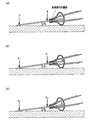
この従来型刃物研磨用ホルダは、包丁の刀身を挟み込む挟持部と、断面略C字形の連結部とを有するホルダ本体と、前記ホルダ本体の開閉を助ける把持部とから構成される発明である。前記発明の構成によれば、ホルダ本体に刀身を挟み込んだ状態で、砥石上に載置し、砥石の上側から刀身に対して押圧することで、刀身の側面が挟持部の内側面に接し、刀身の砥石に対する当接角度を例えばθ0度と設定するものである(図2(a)参照)。そして、砥石の上側から刀身に対して押圧する力を維持しながら、前後に擦動することで、刀身の切歯角度をθ0度とすることが可能となる発明であった。
しかしながら、前記した従来型刃物研磨用ホルダの構成の場合、砥石と刀身の当接角度をθ0とすることができるが、擦動する際の力の加え具合により、刀身が揺動してしまい、刀身の当接角度θ0を一定に保つことができなかった。
具体的には、包丁に対する砥石方向の押し当てる力F1が弱くなると、図2(b)のように、刀身の側面が挟持部の内側面から浮いてしまい、砥石に当接角度θ1がθ0に比べて大きくなる。一方で、力F2が強すぎると、図2(c)のようになり、擦動中に刀身の切刃の当接角度θ2がθ0に比べ小さくなる。
つまり、前記従来型刃物研磨用ホルダの構成によれば、擦動時の加える力の大きさによって、当接角度θ0が変化してしまうといった問題が生じていた。
However, in the case of the configuration of the above-described conventional blade polishing holder, the contact angle between the grindstone and the blade can be set to θ 0 , but the blade swings due to the applied force when rubbing. The blade contact angle θ 0 could not be kept constant.
Specifically, the force F 1 for pressing the grinding direction for knife is weakened, as in FIG. 2 (b), the side surface of the blade is cause to float from the inner surface of the clamping portion, the contact angle theta 1 to the grinding wheel It becomes larger than the θ 0. On the other hand, when the force F 2 is too strong, the contact angle θ 2 of the blade of the blade becomes smaller than θ 0 during the friction as shown in FIG.
That is, according to the configuration of the conventional blade polishing holder, there is a problem that the contact angle θ 0 changes depending on the magnitude of the force applied during the friction.
そこで、本発明は、前記課題に鑑み、包丁の刀身を所定の角度で研磨することを可能とし、包丁の切れ味の維持を図る刃物研磨用ホルダを提供することを目的とする。 In view of the above problems, an object of the present invention is to provide a blade polishing holder that can polish the blade of a knife at a predetermined angle and maintain the sharpness of the knife.
前記課題を解決するため、本発明の請求項1に係る刃物研磨用ホルダは、包丁の刀身を挟持する一対の挟持片からなる挟持部と、前記一対の挟持片の基端側と結合し、前記一対の挟持片を互いに近接する方向に付勢する断面略C字形の連結部と、合成樹脂からなり、前記連結部の内周面を被覆する保護部材と、を含んでなる刃物研磨用ホルダにおいて、前記保護部材は、前記挟持片側に向って突出し、前記挟持部に挟まれた包丁の刀身のみね側を収納可能な溝を形成する一対の突起部を含む係止部を有し、前記一対の突起部が形成する溝は、前記挟持部に向って溝幅が広くなる略V字形であることを特徴とする。
In order to solve the above-mentioned problem, the blade polishing holder according to
請求項2係る発明は、前記一対の突起部が形成する溝の底部側に対応する位置に、前記連結部の溝が形成されていることを特徴とする。 The invention according to claim 2 is characterized in that the groove of the connecting portion is formed at a position corresponding to the bottom side of the groove formed by the pair of protrusions .
請求項3に係る発明は、請求項1または請求項2に記載の刃物研磨用ホルダにおいて、前記連結部の外周面に補強材を備えたことを特徴とする。請求項3に係る発明によれば、砥石に当接する連結部の外周面側を保護し、磨耗を抑えることができる。
According to a third aspect of the present invention, in the blade polishing holder according to the first or second aspect, a reinforcing material is provided on the outer peripheral surface of the connecting portion. According to the invention which concerns on
請求項4に係る発明は、請求項1乃至請求項3のいつずれか一つに記載の刃物研磨用ホルダにおいて、孔部を有する前記連結部と、一端が前記一対の挟持片に取り付けられ、他端が前記孔部を貫孔して、前記一対の挟持片の反対側に延出する一対の把持片からなる把持部とを有することを特徴とする。
請求項4に係る発明によれば、刃物研磨ホルダに対して、包丁の刀身の着脱作業が容易となる。また、把持片が連結部の外側ではなく、内部を貫通すことによって、把持片が砥石を干渉することがない。
The invention according to claim 4 is the blade polishing holder according to any one of
According to the invention which concerns on Claim 4 , the attachment or detachment operation | work of the blade of a knife becomes easy with respect to a blade grinding | polishing holder. In addition, the gripping piece does not interfere with the grindstone when the gripping piece penetrates not the outside of the connecting portion but the inside.
請求項5に係る発明は、請求項1乃至請求項4のいずれか一つに記載の刃物研磨用ホルダにおいて、前記一対の挟持片の内側を被覆する保護部材をさらに設けることを特徴とする。
請求項5に係る発明によれば、挟持部ではなく、保護部材が包丁の刀身と直接接触するため、刀身が傷つきにくくなる一方で、刀身が滑りにくくなる。
According to a fifth aspect of the present invention, in the blade polishing holder according to any one of the first to fourth aspects, a protective member that covers the inside of the pair of clamping pieces is further provided.
According to the invention which concerns on Claim 5 , since not a clamping part but a protection member contacts with the blade of a knife directly, while a blade becomes difficult to be damaged, a blade becomes difficult to slip.
本願発明によれば、研磨作業中において、摺動する際の力加減に関わらず、刀身と砥石の当接角度が一定となるため、研磨後の切歯部分の角度を所定の角度にすることができる。その結果、包丁の切れ味の維持を図ることができる。 According to the present invention, the contact angle between the blade and the grindstone is constant regardless of the force applied during sliding during the polishing operation, so the angle of the incisor portion after polishing is set to a predetermined angle. Can do. As a result, the sharpness of the knife can be maintained.
次に、本発明の実施形態について、適宜図面を参照しながら詳細に説明する。図3は、実施形態に係る刃物研磨用ホルダ1全体を示す斜視図であり、図4は、図3に図示する刃物研磨用ホルダ1の正面図である。
Next, embodiments of the present invention will be described in detail with reference to the drawings as appropriate. FIG. 3 is a perspective view illustrating the entire
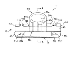
図3及び図4に示すように、本実施形態の刃物研磨用ホルダ1は、包丁の刀身を挟み込むホルダ本体10と、前記ホルダ本体10内部に設けられた係止部20と,前記ホルダ本体10の内周面側に固着された保護部材30と、前記ホルダ本体10の外周面に固定された補強材40と、ホルダ本体10に取り付けられた把持部50とを備えて構成されている。また、図5は、図4のA−A線断面図であるが、刃物研磨用ホルダ1は、中心軸Cを軸に左右対称に形成されている。
As shown in FIGS. 3 and 4, the
ホルダ本体10は、包丁の刀身を挟み込む一対の挟持片11a、11aを有する挟持部11と、前記一対の挟持片11a、11aの基端側に結合する連結部12とを備えてなるが、これらは一枚のステンレス板、鋼板等をプレス成形して一体的に形成されてなる。
The
挟持部11は、一対の挟持片11a、11aからなる。挟持片11aは、図5に示すように、刀身の側面を挟み持つ先端部11bと、連結部12の開口部12aと一体的に形成され結合する基端部11cを有する。また、先端部11bが挟持される刀身の側面に対し並行となるように、挟持片11aは略く字形からなる。これにより、包丁の刀身を安定して挟持することができる。また、挟持される刀身がスライドすることを防止することができ、研磨中に、係止部20に係合した刀身のみねが抜け出すことがない。
後述する保護部材30の突起部30aが貫孔するための、略矩形状に打ち抜き加工された孔部11d(図4参照)を有する。
The clamping
It has a
連結部12の形状は、図4に示すように正面視略矩形状であって、側面視においては図5に示すように略C字状である。
また、図5に示すように、連結部12の開口部12aは、挟持片11aの基端部11cと一体的に形成されてなる。これにより、挟持片11a、11aが開口したとしても、近接するように弾性付勢する。
また、連結部12には、打ち抜き加工により把持片用孔部12b、12c(図5参照)と補強材用孔部12d(図3参照)が形成される。
The shape of the connecting
Moreover, as shown in FIG. 5, the
The connecting
保護部材30は、刀身の側面を挟持片11aが直接挟持して傷がつくことを防止するためものであるため、材質としては刀身よりも硬度が低いポリエチレン(PE)等の合成樹脂が挙げられる。保護部材30の形状は、ホルダ本体10と略同一形状であるが、刀身のみねが係合し易くするために、後述する溝20aを被覆することが望ましい。また、挟持片11aの先端側11bを覆うように延出しても良い(図5参照)。これによれば、刀身が挟持片11aの先端部11bに接触し、傷つくことを防止することができる。保護部材30は、ホルダ本体10の内周面側に接着剤により固着してもよいが、本実施形態のように、挟持片11aに形成された孔部11dに対応する箇所に、返しが付いた突起部30aを設けて当該孔部11dに嵌め込み、保護部材30をホルダ本体10に固定してもよい。また、保護部材30には、図5に示すように、後述する一対の把持片50a、50aが貫孔する把持片用孔部30b、30cを設けている。
Since the
本実施形態に係る係止部20は、図3及び図5に示すように溝20aと一対の突起物20b、20bとからなる。溝20aは、前記連結部12の内周面に形成された断面略U字形の溝であるが、当該形状に限られず、断面略コ字形の溝であってもよい。また、溝20aは、刀身のみねが収納出来る大きさを有することが必要である。
一対の突起物20b、20bは、前記溝20aの縁付近の保護部材30を、溝20aから挟持片11aの方に向かって突出した形状からなる。また、一対の突起物20b、20bは、保護部材30と一体に形成されている。
このように、溝20aと突起物20b、20bとからなる係止部20を連結部12内に配置すれば、ホルダ本体10に挟持される刀身のみね側が係合することができる。そして、刀身の上側から力を加えたとしても、砥石と刀身の当接角度が変わることなく、一定の当接角度を維持しながら、刀身を研磨することが可能となる。
また、溝20aと一対の突起物20b、20bとから形成される係止部20の形状が、断面略V字の形状であれば、幅の異なる刀身にも係合可能となるため、望ましい。
As shown in FIGS. 3 and 5, the
The pair of
Thus, if the latching | locking
In addition, it is desirable that the shape of the locking
補強材40は、図4に示すように正面視略矩形状からなるが、本発明において当該形状に限られず、連結部12の外周面を覆うような形状であればよい。
補強材40は、連結部12の外周面にスポット溶接等により固定するが、その他に、補強材用孔部12dに嵌合するように延出する突起部40aを設けてもよい(図3参照)。これによれば、補強材40の長手方向に摺動させても、突起部40aが補強材用孔12dに引っ掛るため、連結部12に対する固定化を強化することができる。
また、補強材40は砥石と接触する部材であるために、補強材40の材質としては、耐摩耗性を有することが望ましい。ここで、耐摩耗性を有するものとしては、例えば、焼入れを行わない鋼材等の軟鋼が望ましい。
As shown in FIG. 4, the reinforcing
The reinforcing
Further, since the reinforcing
把持部50は、一対の把持片50a、50aからなる。把持片50aは、一枚のステンレス、鋼等の板を、正面視略T字状に成形してなるが、当該形状に限るものではない。
図5に示すように、把持片50aの一端側は、挟持片11aの外周面にスポット溶接等により固定される。また、他端側は、前記連結部12に形成された把持片用孔部12b、12cと、前記保護部材30に形成された把持片用孔部30b、30cを貫孔し延出してなる。このように、把持片50aを連結部12等の外側ではなく、内部を通すことによって、把持片50aが砥石を干渉することがなくなる。
また、使用者が把持片50aを押圧し易くするための凹部50bと、挟持する際に加わる力による変形を防止するためのリブ部50cが形成されても良い。
The
As shown in FIG. 5, one end side of the
Moreover, the recessed
以上の構成によれば、把持片50a、50aを近接する方向に、凹部50b、50bを押圧することにより、挟持片11a、11aが開口する。そして、刀身を開口している前記先端部11b、11b側から間挿し、刀身のみねが係止部20に収納することができる。また、連結部12の弾性付勢により、挟持片11a、11aが閉口するため、刀身を挟持することが可能となる。
According to the above configuration, the clamping
次に、図6〜図8を用いて刃物研磨用ホルダ1を用いた包丁2の研磨方法につき、説明する。図6は、包丁の刀身に対して、刃物研磨用ホルダ1の装着方法を示す図であって、
図6(a)は、刃物研磨用ホルダ1の開口方法を示す状態を、図6(b)は、刃物研磨用ホルダ1に対し、包丁の刀身を挿入の状態を、図6(c)は、刃物研磨用ホルダ1が刀身を挟み持った状態を示す図である。図7は、刃物研磨用ホルダ1の使用状態を表す側面視断面図であって、図7(a)は、包丁を挟み込んだ刃物研磨用ホルダ1を砥石上に載置した状態を、図7(b)は、積載された刃物研磨用ホルダ1を摺動する状態を示す図である。図8は、刃物研磨用ホルダ1を用いて包丁2を研磨している状態を示す斜視図である。
Next, a method for polishing the knife 2 using the
6 (a) shows a state of the opening method of the
まず、刃物研磨用ホルダ1の装着方法を説明する。把持片50a、50aの凹部50b、50bに手指を当て、図6(a)で示す白抜きの矢印方向に加圧する。これにより、把持片50a、50aと結合する挟持片11a、11aは開口する。そして、図6(b)に示すように開口する挟持片11a、11aの間に、包丁の刀身2aのみね2c側を向けて挿入する。その際、刀身2aのみね2cが溝20aを覆う保護部材30に当接するまで、押し込む。そして、前記加圧を止めると、連結部12の弾性付勢により、11a、11aは閉口し、図6(c)に示すように刀身2aを挟み持つことができる。このような方法により、刃物研磨用ホルダ1を包丁に装着される。
First, a method for mounting the
次に、刃物研磨用ホルダ1を装着した包丁の研磨方法について説明する。図7(a)において示すように刀身2aを挟み込んだ刃物研磨用ホルダ1を、砥石3上に置く。この状態において、砥石3に対する刀身2aの当接角度がθとなる。
前記状態を保ちながら、図8に示すように、砥石3の上側から刀身に対し力を加えながら、砥石3上を繰り返し摺動する。これにより、刀身2aを研ぐことができる。ここで、図7(b)は、擦動時の状態を示す側面断面図であるが、擦動時の力が加わったとしても、刀身2aのみね2c側が係止部20内に収納し係止するため、図7(a)に示した当接角度θは変化することなく、一定の角度を保ちながら研ぐことが可能となる。これにより、刀身2aの切歯部分2bの角度をθとすることができる。
Next, a method for polishing a knife equipped with the
While maintaining the state, as shown in FIG. 8, sliding is repeatedly performed on the
刀身の片面を研磨したら、刃物研磨用ホルダ1を装着した包丁2を反転させ、他面側も前記した方法により研磨する。尚、包丁2を研磨する際には、水、油等の潤滑油を適宜使用しても良い。
When one side of the blade is polished, the knife 2 equipped with the
尚、当接角度θは、一般的に日本用包丁であれば10〜15度、また、欧米用包丁では約30〜40度が望ましい。
また、当接角度θは、刀身の幅と研磨用ホルダの形状が決まるが、連結部12の断面略C字形の半径が小さいものであれば、当接角度θは小さくなり、半径が大きいものであれば、当接角度θは大きくなる。従って、切歯の最適角度に合わせて連結部12の形状を設定すれば、刀身と砥石が所望の角度で当接させることが出来る。
In general, the contact angle θ is preferably 10 to 15 degrees for a Japanese knife, and about 30 to 40 degrees for a Western knife.
Further, the contact angle θ is determined by the width of the blade and the shape of the polishing holder, but if the radius of the substantially C-shaped cross section of the connecting
上述した本実施形態に係る刃物研磨用ホルダ1によれば、挟持部11に挟みこまれる刀身のみね側が、係止部20である溝に係合するため、刀身2aが揺動運動することがなく、砥石3に対する刀身2aの当接角度が常に一定となる。
According to the
以上、実施形態に係る刃物研磨用ホルダ1に基づき、本発明を具体的に説明した。次に図9と図10に基づいて、刃物研磨用ホルダ1の変形例である刃物研磨用ホルダ101について説明する。図9は、刃物研磨用ホルダ101の全体を示す斜視図である。図10は、刃物研磨用ホルダ101に対する包丁の刀身の挟持つ方法を示す図であって、(a)は刃先を刃物研磨用ホルダ101の係止部120に当接した状態、(b)は、刀身102aが刃物研磨用ホルダ101に挟持される段階を示す図である。
The present invention has been specifically described above based on the
図9に示される刃物研磨用ホルダ101は、前述した刃物研磨用ホルダ1と異なって、把持部50を備えていない。また、係止部120も、刃物研磨用ホルダ1の係止部20と異なり、突起部20bを有しない。
刃物研磨用ホルダ101は、挟持部111と連結部112とからなるホルダ本体110と、係止部120と保護部材130と補強材140とを備えている。
尚、連結部112は、実施形態で説明した連結部12と同一である。また、同様に挟持部111は挟持部11と、係止部120に係る溝120aは係止部20に係る溝aと、ホルダ本体110は刃物研磨用ホルダ10と、保護部材120は保護部材20と補強材140は補強材40と同一であるため、説明を省略する。
Unlike the above-described
The
The connecting portion 112 is the same as the connecting
以下、刃物研磨用ホルダ101の使用方法につき、説明する。まず、図10(a)に示すように、包丁の刀身102aのみね102cを、係止部120である溝120aに向けて、刃先102dを溝に当接させる。そして、図10(b)に示すように、包丁をホルダ本体110に向かって押圧する。これによって、包丁の刀身102aが挟持部111に挟み込まれる。以下、段落0025以下で説明した方法によって、刀身2aの研磨を行う。変形例である刃物研磨用ホルダ101によっても、包丁の刀身を一定の角度にて研磨することが出来る。
Hereinafter, a method of using the
以上、実施形態に係る研磨用ホルダ1等について説明したが、本発明は本実施形態に限定されるものではなく、適宜変更して実施することが出来る。
The polishing
1 刃物研磨用ホルダ
2 包丁
2a 刀身
2b 切刃
2c みね
3 砥石
10 ホルダ本体
11 挟持部
11a 挟持片
12 連結部
20 係止部
20a 溝
20b 突起物
30 保護部材
40 補強材
50 把持部
101 刃物研磨用ホルダ
102a 刀身
102c みね
102d 刃先
110 ホルダ本体
111 挟持部
112 連結部
120 係止部
130 保護部材
140 補強材
DESCRIPTION OF
Claims (5)
前記保護部材は、前記挟持片側に向って突出し、前記挟持部に挟まれた包丁の刀身のみね側を収納可能な溝を形成する一対の突起部を含む係止部を有し、前記一対の突起部が形成する溝は、前記挟持部に向って溝幅が広くなる略V字形であることを特徴とする刃物研磨用ホルダ。 A sandwiching portion composed of a pair of sandwiching pieces for sandwiching the blade of a kitchen knife, and a connecting portion having a substantially C-shaped cross section that is coupled to a proximal end side of the pair of sandwiching pieces and biases the pair of sandwiching pieces in a direction approaching each other And a protection member for covering the inner peripheral surface of the connecting portion , made of synthetic resin, and a blade polishing holder comprising:
The protective member has a locking portion that includes a pair of protrusions that protrude toward the holding piece side and that form a groove that can accommodate the blade side of the knife sandwiched between the holding portions. The groove formed by the protruding portion is a substantially V-shaped holder whose groove width becomes wider toward the clamping portion.
Priority Applications (5)
| Application Number | Priority Date | Filing Date | Title |
|---|---|---|---|
| JP2007149921A JP4436385B2 (en) | 2007-06-06 | 2007-06-06 | Blade polishing holder |
| DE602007007307T DE602007007307D1 (en) | 2007-06-06 | 2007-09-05 | Cutting tool for grinding |
| AT07253513T ATE471787T1 (en) | 2007-06-06 | 2007-09-05 | CUTTING TOOL FOR GRINDING |
| DK07253513.1T DK2000255T3 (en) | 2007-06-06 | 2007-09-05 | Cutting tool holder for use in grinding |
| EP07253513A EP2000255B1 (en) | 2007-06-06 | 2007-09-05 | Cutting-tool holder for use in grinding |
Applications Claiming Priority (1)
| Application Number | Priority Date | Filing Date | Title |
|---|---|---|---|
| JP2007149921A JP4436385B2 (en) | 2007-06-06 | 2007-06-06 | Blade polishing holder |
Publications (2)
| Publication Number | Publication Date |
|---|---|
| JP2008302447A JP2008302447A (en) | 2008-12-18 |
| JP4436385B2 true JP4436385B2 (en) | 2010-03-24 |
Family
ID=38625875
Family Applications (1)
| Application Number | Title | Priority Date | Filing Date |
|---|---|---|---|
| JP2007149921A Active JP4436385B2 (en) | 2007-06-06 | 2007-06-06 | Blade polishing holder |
Country Status (5)
| Country | Link |
|---|---|
| EP (1) | EP2000255B1 (en) |
| JP (1) | JP4436385B2 (en) |
| AT (1) | ATE471787T1 (en) |
| DE (1) | DE602007007307D1 (en) |
| DK (1) | DK2000255T3 (en) |
Families Citing this family (2)
| Publication number | Priority date | Publication date | Assignee | Title |
|---|---|---|---|---|
| KR200450345Y1 (en) * | 2009-04-14 | 2010-09-24 | 김경희 | Supporter of a grindstone |
| CN103331657A (en) * | 2013-06-24 | 2013-10-02 | 苏州快吉刀片制造有限公司 | Blade belt positioner |
Family Cites Families (4)
| Publication number | Priority date | Publication date | Assignee | Title |
|---|---|---|---|---|
| US852750A (en) * | 1906-03-28 | 1907-05-07 | Edward W Wheeler | Holder for razor-blades. |
| US1470514A (en) * | 1922-10-07 | 1923-10-09 | Voges Ernest | Razor-blade sharpener |
| US3924360A (en) * | 1971-11-04 | 1975-12-09 | Paul C Haile | Knife sharpener |
| JP3968101B2 (en) * | 2005-01-26 | 2007-08-29 | マスター カットラリー 株式会社 | Blade polishing holder |
-
2007
- 2007-06-06 JP JP2007149921A patent/JP4436385B2/en active Active
- 2007-09-05 AT AT07253513T patent/ATE471787T1/en not_active IP Right Cessation
- 2007-09-05 DE DE602007007307T patent/DE602007007307D1/en active Active
- 2007-09-05 DK DK07253513.1T patent/DK2000255T3/en active
- 2007-09-05 EP EP07253513A patent/EP2000255B1/en not_active Not-in-force
Also Published As
| Publication number | Publication date |
|---|---|
| DE602007007307D1 (en) | 2010-08-05 |
| ATE471787T1 (en) | 2010-07-15 |
| EP2000255A1 (en) | 2008-12-10 |
| EP2000255B1 (en) | 2010-06-23 |
| DK2000255T3 (en) | 2010-09-27 |
| JP2008302447A (en) | 2008-12-18 |
Similar Documents
| Publication | Publication Date | Title |
|---|---|---|
| US8381407B1 (en) | Exchange blade knife | |
| US5291805A (en) | Sharpening and deburring tool | |
| US20060246830A1 (en) | Sanding tool | |
| US4550632A (en) | Knife sharpener | |
| JP4436385B2 (en) | Blade polishing holder | |
| US7112128B1 (en) | Sanding tool with protective clamping mechanism | |
| US5679068A (en) | Sharpening and deburring tool with unitary blade guard and handle | |
| JP3968101B2 (en) | Blade polishing holder | |
| CA2589436A1 (en) | Sharpening and deburring tool for single and double edge type cutting blades | |
| KR20070078353A (en) | Folder type cutter with abrasive device | |
| US8978254B1 (en) | Exchange blade knife | |
| WO2001014108A1 (en) | Cutting apparatus | |
| US10870309B2 (en) | Sharpener | |
| JP3087779U (en) | Tool for sharpening blades | |
| CN109843523A (en) | Hair cutting apparatus | |
| JP2004160636A (en) | Cutter sharpening holder | |
| JP3112398U (en) | Blade sharpener | |
| CN219311326U (en) | Curve scissors | |
| GB2134020A (en) | Knife sharpener | |
| CN210414630U (en) | Scissors of portable tool | |
| CN216030948U (en) | Scissors with sharpening function | |
| US701878A (en) | Pocket-knife leather-punch. | |
| CA2134011C (en) | Knife sharpening steel | |
| JP2004229744A (en) | Cutter | |
| JP6130337B2 (en) | Nail resection tool |
Legal Events
| Date | Code | Title | Description |
|---|---|---|---|
| A621 | Written request for application examination |
Free format text: JAPANESE INTERMEDIATE CODE: A621 Effective date: 20090421 |
|
| A977 | Report on retrieval |
Free format text: JAPANESE INTERMEDIATE CODE: A971007 Effective date: 20090813 |
|
| A131 | Notification of reasons for refusal |
Free format text: JAPANESE INTERMEDIATE CODE: A131 Effective date: 20090818 |
|
| A521 | Request for written amendment filed |
Free format text: JAPANESE INTERMEDIATE CODE: A523 Effective date: 20091015 |
|
| TRDD | Decision of grant or rejection written | ||
| A01 | Written decision to grant a patent or to grant a registration (utility model) |
Free format text: JAPANESE INTERMEDIATE CODE: A01 Effective date: 20091208 |
|
| A01 | Written decision to grant a patent or to grant a registration (utility model) |
Free format text: JAPANESE INTERMEDIATE CODE: A01 |
|
| A61 | First payment of annual fees (during grant procedure) |
Free format text: JAPANESE INTERMEDIATE CODE: A61 Effective date: 20091225 |
|
| R150 | Certificate of patent or registration of utility model |
Free format text: JAPANESE INTERMEDIATE CODE: R150 |
|
| FPAY | Renewal fee payment (event date is renewal date of database) |
Free format text: PAYMENT UNTIL: 20130108 Year of fee payment: 3 |
|
| FPAY | Renewal fee payment (event date is renewal date of database) |
Free format text: PAYMENT UNTIL: 20160108 Year of fee payment: 6 |
|
| R250 | Receipt of annual fees |
Free format text: JAPANESE INTERMEDIATE CODE: R250 |
|
| R250 | Receipt of annual fees |
Free format text: JAPANESE INTERMEDIATE CODE: R250 |