JP4435965B2 - Blood pump drive - Google Patents
Blood pump drive Download PDFInfo
- Publication number
- JP4435965B2 JP4435965B2 JP2000344451A JP2000344451A JP4435965B2 JP 4435965 B2 JP4435965 B2 JP 4435965B2 JP 2000344451 A JP2000344451 A JP 2000344451A JP 2000344451 A JP2000344451 A JP 2000344451A JP 4435965 B2 JP4435965 B2 JP 4435965B2
- Authority
- JP
- Japan
- Prior art keywords
- chamber
- pressure
- blood pump
- gas
- gas chamber
- Prior art date
- Legal status (The legal status is an assumption and is not a legal conclusion. Google has not performed a legal analysis and makes no representation as to the accuracy of the status listed.)
- Expired - Fee Related
Links
Images


Classifications
-
- A—HUMAN NECESSITIES
- A61—MEDICAL OR VETERINARY SCIENCE; HYGIENE
- A61M—DEVICES FOR INTRODUCING MEDIA INTO, OR ONTO, THE BODY; DEVICES FOR TRANSDUCING BODY MEDIA OR FOR TAKING MEDIA FROM THE BODY; DEVICES FOR PRODUCING OR ENDING SLEEP OR STUPOR
- A61M60/00—Blood pumps; Devices for mechanical circulatory actuation; Balloon pumps for circulatory assistance
- A61M60/40—Details relating to driving
- A61M60/424—Details relating to driving for positive displacement blood pumps
- A61M60/427—Details relating to driving for positive displacement blood pumps the force acting on the blood contacting member being hydraulic or pneumatic
- A61M60/435—Details relating to driving for positive displacement blood pumps the force acting on the blood contacting member being hydraulic or pneumatic with diastole or systole switching by valve means located between the blood pump and the hydraulic or pneumatic energy source
-
- A—HUMAN NECESSITIES
- A61—MEDICAL OR VETERINARY SCIENCE; HYGIENE
- A61M—DEVICES FOR INTRODUCING MEDIA INTO, OR ONTO, THE BODY; DEVICES FOR TRANSDUCING BODY MEDIA OR FOR TAKING MEDIA FROM THE BODY; DEVICES FOR PRODUCING OR ENDING SLEEP OR STUPOR
- A61M60/00—Blood pumps; Devices for mechanical circulatory actuation; Balloon pumps for circulatory assistance
- A61M60/10—Location thereof with respect to the patient's body
- A61M60/122—Implantable pumps or pumping devices, i.e. the blood being pumped inside the patient's body
- A61M60/126—Implantable pumps or pumping devices, i.e. the blood being pumped inside the patient's body implantable via, into, inside, in line, branching on, or around a blood vessel
- A61M60/135—Implantable pumps or pumping devices, i.e. the blood being pumped inside the patient's body implantable via, into, inside, in line, branching on, or around a blood vessel inside a blood vessel, e.g. using grafting
- A61M60/139—Implantable pumps or pumping devices, i.e. the blood being pumped inside the patient's body implantable via, into, inside, in line, branching on, or around a blood vessel inside a blood vessel, e.g. using grafting inside the aorta, e.g. intra-aortic balloon pumps
-
- A—HUMAN NECESSITIES
- A61—MEDICAL OR VETERINARY SCIENCE; HYGIENE
- A61M—DEVICES FOR INTRODUCING MEDIA INTO, OR ONTO, THE BODY; DEVICES FOR TRANSDUCING BODY MEDIA OR FOR TAKING MEDIA FROM THE BODY; DEVICES FOR PRODUCING OR ENDING SLEEP OR STUPOR
- A61M60/00—Blood pumps; Devices for mechanical circulatory actuation; Balloon pumps for circulatory assistance
- A61M60/10—Location thereof with respect to the patient's body
- A61M60/122—Implantable pumps or pumping devices, i.e. the blood being pumped inside the patient's body
- A61M60/196—Implantable pumps or pumping devices, i.e. the blood being pumped inside the patient's body replacing the entire heart, e.g. total artificial hearts [TAH]
-
- A—HUMAN NECESSITIES
- A61—MEDICAL OR VETERINARY SCIENCE; HYGIENE
- A61M—DEVICES FOR INTRODUCING MEDIA INTO, OR ONTO, THE BODY; DEVICES FOR TRANSDUCING BODY MEDIA OR FOR TAKING MEDIA FROM THE BODY; DEVICES FOR PRODUCING OR ENDING SLEEP OR STUPOR
- A61M60/00—Blood pumps; Devices for mechanical circulatory actuation; Balloon pumps for circulatory assistance
- A61M60/20—Type thereof
- A61M60/295—Balloon pumps for circulatory assistance
-
- A—HUMAN NECESSITIES
- A61—MEDICAL OR VETERINARY SCIENCE; HYGIENE
- A61M—DEVICES FOR INTRODUCING MEDIA INTO, OR ONTO, THE BODY; DEVICES FOR TRANSDUCING BODY MEDIA OR FOR TAKING MEDIA FROM THE BODY; DEVICES FOR PRODUCING OR ENDING SLEEP OR STUPOR
- A61M60/00—Blood pumps; Devices for mechanical circulatory actuation; Balloon pumps for circulatory assistance
- A61M60/40—Details relating to driving
- A61M60/424—Details relating to driving for positive displacement blood pumps
- A61M60/427—Details relating to driving for positive displacement blood pumps the force acting on the blood contacting member being hydraulic or pneumatic
- A61M60/43—Details relating to driving for positive displacement blood pumps the force acting on the blood contacting member being hydraulic or pneumatic using vacuum at the blood pump, e.g. to accelerate filling
-
- A—HUMAN NECESSITIES
- A61—MEDICAL OR VETERINARY SCIENCE; HYGIENE
- A61M—DEVICES FOR INTRODUCING MEDIA INTO, OR ONTO, THE BODY; DEVICES FOR TRANSDUCING BODY MEDIA OR FOR TAKING MEDIA FROM THE BODY; DEVICES FOR PRODUCING OR ENDING SLEEP OR STUPOR
- A61M60/00—Blood pumps; Devices for mechanical circulatory actuation; Balloon pumps for circulatory assistance
- A61M60/40—Details relating to driving
- A61M60/497—Details relating to driving for balloon pumps for circulatory assistance
-
- A—HUMAN NECESSITIES
- A61—MEDICAL OR VETERINARY SCIENCE; HYGIENE
- A61M—DEVICES FOR INTRODUCING MEDIA INTO, OR ONTO, THE BODY; DEVICES FOR TRANSDUCING BODY MEDIA OR FOR TAKING MEDIA FROM THE BODY; DEVICES FOR PRODUCING OR ENDING SLEEP OR STUPOR
- A61M60/00—Blood pumps; Devices for mechanical circulatory actuation; Balloon pumps for circulatory assistance
- A61M60/50—Details relating to control
- A61M60/508—Electronic control means, e.g. for feedback regulation
- A61M60/538—Regulation using real-time blood pump operational parameter data, e.g. motor current
-
- A—HUMAN NECESSITIES
- A61—MEDICAL OR VETERINARY SCIENCE; HYGIENE
- A61M—DEVICES FOR INTRODUCING MEDIA INTO, OR ONTO, THE BODY; DEVICES FOR TRANSDUCING BODY MEDIA OR FOR TAKING MEDIA FROM THE BODY; DEVICES FOR PRODUCING OR ENDING SLEEP OR STUPOR
- A61M60/00—Blood pumps; Devices for mechanical circulatory actuation; Balloon pumps for circulatory assistance
- A61M60/10—Location thereof with respect to the patient's body
- A61M60/122—Implantable pumps or pumping devices, i.e. the blood being pumped inside the patient's body
- A61M60/126—Implantable pumps or pumping devices, i.e. the blood being pumped inside the patient's body implantable via, into, inside, in line, branching on, or around a blood vessel
- A61M60/148—Implantable pumps or pumping devices, i.e. the blood being pumped inside the patient's body implantable via, into, inside, in line, branching on, or around a blood vessel in line with a blood vessel using resection or like techniques, e.g. permanent endovascular heart assist devices
-
- A—HUMAN NECESSITIES
- A61—MEDICAL OR VETERINARY SCIENCE; HYGIENE
- A61M—DEVICES FOR INTRODUCING MEDIA INTO, OR ONTO, THE BODY; DEVICES FOR TRANSDUCING BODY MEDIA OR FOR TAKING MEDIA FROM THE BODY; DEVICES FOR PRODUCING OR ENDING SLEEP OR STUPOR
- A61M60/00—Blood pumps; Devices for mechanical circulatory actuation; Balloon pumps for circulatory assistance
- A61M60/20—Type thereof
- A61M60/247—Positive displacement blood pumps
- A61M60/253—Positive displacement blood pumps including a displacement member directly acting on the blood
- A61M60/268—Positive displacement blood pumps including a displacement member directly acting on the blood the displacement member being flexible, e.g. membranes, diaphragms or bladders
- A61M60/274—Positive displacement blood pumps including a displacement member directly acting on the blood the displacement member being flexible, e.g. membranes, diaphragms or bladders the inlet and outlet being the same, e.g. para-aortic counter-pulsation blood pumps
Description
【0001】
【発明の属する技術分野】
本発明は、人工心臓ポンプや大動脈内バルーンポンプのような生体の血液循環あるいは血液循環補助のための血液ポンプを駆動する血液ポンプ駆動装置に関するもので、特に、拍動する血液ポンプのポンピング拍出容量あるいは血液ポンプのストローク変位状況を検出することができる血液ポンプ駆動装置に関する。
【0002】
【従来の技術】
生体に接続された血液ポンプにおいて、ポンピング容量は、心臓の回復状況や血液循環系抵抗に関係するので、生体状況を知るためにも重要であり、血液ポンプの作動の正しさを確認するための基本的情報でもある。
【0003】
また、血液ポンプで最大限の拍出を得るためには、ポンプのストローク変位を監視して血液ポンプをフルにストロークさせることが望ましい。すなわち、血液ポンプがフルに充満したらすぐに血液を拍出させ、フルに拍出したらすぐに血液を吸引させるように制御することが望ましい。
【0004】
血液ポンプのポンピング容量やストローク変位状況を検出することのできる従来の装置としては、血液ポンプと生体とを結ぶ配管に流量計を配設して血液の流量を測定する方法に基づくものがあった。
【0005】
また、例えば特開平6−261872号公報に記載のように、血液ポンプに位置検出装置を配設して血液ポンプのピストンの変位を測定する方法に基づくものがあった。
【0006】
またはDiagnosis of Mechanical Failures of Total Artificial Hearts (Vol.XXXI Trans
Am Soc Artif Intern Organs 1985 79 〜81頁) に示されるように、血液ポンプを駆動した空気量を計測するために、大気開放する際の空気流量を積分して求める方法に基づくものがあった。
【0007】
【発明が解決しようとする課題】
上記従来の装置においては、いずれも患者に精密な計測センサを近接させることになり、さらに患者から離れた計測装置への配線等が必要となり、安全確保の観点から患者の活動を制限せざるをえないという問題があった。
【0008】
また前記Diagnosis of Mechanical Failures of Total Artificial Hearts に示される方法においては、空気流量を積分する必要があることにより、計測精度の点や装置が大掛かりになるなどの問題があった。
【0009】
さらに血液ポンプは、拍出時には血圧負荷がかかるので、吸引時よりも負荷が大きくなり、往復動作の負荷がアンバランスとなる。そのために、単一モータの正逆回転で駆動する場合に制御が複雑になり、また、消費電力も大きくなるという問題があり、駆動装置の小型化のための障害となっていた。
【0010】
また血液ポンプは、上述のように拍出時の方が吸引時よりも血圧負荷が大きいため、拍出時のモータ回転数が吸引時と比較して非常に高くなり、拍出時のモータ回転数が頭打ちとなって血液拍出量が伸びないという問題があった。
【0011】
そこで本発明者は、気体室とその気体室から可動部材で分離された流体室とを備えたオイルリザーバの前記気体室に蓄圧室を接続し、その蓄圧室により前記気体室内の気体圧を蓄圧して、オイルリザーバの前記流体室に充填された流体をポンプ手段により血液ポンプに吐出させるようにすると、蓄圧室が前記ポンプ手段の吸引過程においてはそのポンプ手段の負荷となり、そこで蓄えた圧力によって、ポンプ手段の吐出過程、すなわち血液ポンプの拍出過程においては前記ポンプ手段を補助することになる、という本発明の技術的思想に着眼し、更に研究開発を重ねた結果、負荷のアンバランスを解消するとともに、患者に近接するセンサを不要にするという目的を達成する本発明に到達した。
【0012】
【課題を解決するための手段】
本発明(請求項1に記載の第1発明)の血液ポンプ駆動装置は、気体室とその気体室から可動部材で分離された流体室とを備えたオイルリザーバと、そのオイルリザーバの前記流体室に充填された流体を血液ポンプに吐出するポンプ手段と、前記オイルリザーバの前記気体室に接続されていてその気体室内の気体圧を蓄圧する蓄圧室と、前記オイルリザーバの前記気体室内の気体圧を検出する圧力測定手段と、を備えているものである。
【0013】
本発明(請求項2に記載の第2発明)の血液ポンプ駆動装置は、前記第1発明において、前記圧力測定手段が、前記蓄圧室に蓄圧された気体圧を検出するように、該蓄圧室に配設されているものである。
【0014】
本発明(請求項3に記載の第3発明)の血液ポンプ駆動装置は、血液ポンプに接続される第1ポートと、オイルリザーバの気体室から可動部材で分離された流体室に接続される第2ポートと、前記第2ポートから吸入した流体を前記第1ポートへ吐出する正方向ポンピングおよび前記第1ポートから吸入した流体を前記第2ポートへ吐出する逆方向ポンピングを交互に行うポンプ手段と、前記オイルリザーバの前記気体室に接続されてその気体室内の気体圧を蓄圧する蓄圧室と、前記気体室内の圧力を測定する圧力測定手段と、前記圧力測定手段の信号により前記ポンプ手段の前記ポンピングを制御する制御装置と、を備えているものである。
【0015】
本発明(請求項4に記載の第4発明)の血液ポンプ駆動装置は、前記第3発明において、前記制御装置が、前記圧力測定手段からの信号の変化量に基づき、前記血液ポンプへの流体の吐出量または吸引量を算出するようにされているものである。
【0016】
本発明(請求項5に記載の第5発明)の血液ポンプ駆動装置は、前記第3発明において、前記制御装置が、前記圧力測定手段からの信号に応じて、前記ポンプ手段の正方向ポンピングと逆方向ポンピングとを切り換えるものとされているものである。
【0017】
本発明(請求項6に記載の第6発明)の血液ポンプ駆動装置は、前記第3発明において、前記気体室が弁手段を介して大気に連通されており、前記気体室の圧力が負圧になると前記制御装置がその弁手段を開放して前記気体室を大気に連通させるように構成されているものである。
【0018】
本発明(請求項7に記載の第7発明)の血液ポンプ駆動装置は、前記第3発明において、前記正方向ポンピングおよび前記逆方向ポンピングのそれぞれにおける前記ポンプ手段の負荷が均等に近づくように、前記気体室の容量または圧力が設定されているものである。
【0019】
本発明(請求項8に記載の第8発明)の血液ポンプ駆動装置は、前記第3発明において、第二の流体室とその第二の流体室から可動部材で分離された第二の気体室とを有する分離室を備え、前記第1ポートが前記第二の流体室に接続され、前記第二の気体室が前記血液ポンプに接続されているものである。
【0020】
本発明(請求項9に記載の第9発明)の血液ポンプ駆動装置は、前記第8発明において、前記制御装置が、前記圧力測定手段からの信号に基づき、前記第二の気体室の気体量を設定するようにされているものである。
【0021】
【発明の作用および効果】
上記構成より成る第1発明の血液ポンプ駆動装置は、気体室と流体室とを備えたオイルリザーバの前記気体室に蓄圧室を接続して、その蓄圧室に前記気体室内の気体圧を蓄圧するようにしているので、その蓄圧室が、血液ポンプの吸引過程、すなわち前記オイルリザーバの流体室に血液ポンプから流体を吸引するポンプ手段の吸引過程においてはそのポンプ手段の負荷となり、そこで蓄えた圧力によって、血液ポンプの拍出過程、すなわちポンプ手段の吐出過程においてはそのポンプ手段を補助する役割を果たすことになる。したがって、血液ポンプの拍出時および吸引時のそれぞれにおける負荷のアンバランスを解消することができる、という効果を奏する。また、圧力測定手段によってオイルリザーバの気体室内の気体圧を検出するようにしているので、その気体圧に基づく制御が可能となるとともに、血液ポンプのポンピング容量の算出が可能となり、患者に近接するセンサを不要にすることができる、という効果を奏する。
【0022】
上記構成より成る第2発明の血液ポンプ駆動装置は、前記第1発明において、その圧力測定手段を蓄圧室に配設して、その蓄圧室に蓄圧された気体圧を検出するようにしているので、蓄圧室に蓄圧された気体圧に基づく制御を可能にするという効果を奏する。
【0023】
上記構成より成る第3発明の血液ポンプ駆動装置は、制御装置が、オイルリザーバの気体室の圧力を測定する圧力測定手段の信号により、第2ポートから吸入した流体を第1ポートへ吐出する正方向ポンピングと第1ポートから吸入した流体を第2ポートへ吐出する逆方向ポンピングとを交互に行うポンプ手段のポンピングを制御するので、そのポンプ手段の正逆回転の負荷を均一にするとともに、患者に近接するセンサを不要にすることができる、という効果を奏する。
【0024】
上記構成より成る第4発明の血液ポンプ駆動装置は、前記第3発明において、前記制御装置が、前記圧力測定手段からの信号の変化量に基づいて、前記血液ポンプへの流体の吐出量または吸引量を算出するようにしているので、その流体の吐出量または吸引量に基づく血液ポンプの制御が可能となり、生体からの血液の流入量および生体への血液の吐出量を精確に制御することができる、という効果を奏する。
【0025】
上記構成より成る第5発明の血液ポンプ駆動装置は、前記第3発明において、前記制御装置が、前記圧力測定手段からの信号に応じて、正方向ポンピングと逆方向ポンピングとを切り換えるようにしているので、前記ポンプ手段の正逆回転の負荷を均等にすることができる、という効果を奏する。
【0026】
上記構成より成る第6発明の血液ポンプ駆動装置は、前記第3発明において、オイルリザーバの気体室が弁手段を介して大気に連通されていて、その気体室の圧力が負圧になると前記制御装置が弁手段を開放してその気体室を大気に連通させるので、前記気体室の圧力が負圧に維持されることを防止して、気体量を適切に維持することができる、という効果を奏する。
【0027】
上記構成より成る第7発明の血液ポンプ駆動装置は、前記第3発明において、前記正方向ポンピングと前記逆方向ポンピングとのそれぞれにおける前記流体ポンプの負荷が均等に近づくように、前記オイルリザーバの気体室の容量または圧力が設定されるので、ポンプ手段の負荷を均等にすることができる、という効果を奏する。
【0028】
上記構成より成る第8発明の血液ポンプ駆動装置は、前記第3発明において、第二の流体室とその第二の流体室から可動部材で分離された第二の気体室とを有する前記分離室を設け、前記第1ポートが第二の流体室に接続され、第二の気体室が血液ポンプに接続されるようにしているので、前記血液ポンプとして空気圧駆動型の血液ポンプを利用することができる、という効果を奏する。
【0029】
上記構成より成る第9発明の血液ポンプ駆動装置は、前記第8発明において、前記制御装置が、前記圧力測定手段からの信号に基づいて前記第二の気体室の空気量を設定するようにしているので、設定された第二の気体室の空気量に基づく制御を可能にするという効果を奏する。
【0030】
【発明の実施の形態】
以下本発明の実施の形態につき、図面を用いて説明する。
【0031】
(第1実施形態)
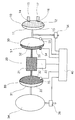
本第1実施形態の血液ポンプ駆動装置は、図1に示されるように、気体室としての空気室33と流体室としての液体室32とを備えたオイルリザーバ30と、そのオイルリザーバ30の液体室32に充填された流体を吐出するポンプ手段としてのオイルポンプ20と、そのオイルポンプ20から吐出された流体によって血液を吸排する血液ポンプ10と、前記オイルリザーバ30の空気室33に接続されていてその空気室33内の気体圧を蓄圧する蓄圧室34とを備えたものである。蓄圧室34は、例えば蓄圧タンクによって構成される。
【0032】
前記オイルリザーバ30は、可動部材としてのダイアフラム31によって気体室としての空気室33と流体室としての液体室32とに分離され、区画形成されている。
【0033】
前記オイルリザーバ30の空気室33は、配管を介してその空気室33内の気体圧を蓄圧する蓄圧室34に接続されている。
【0034】
前記オイルポンプ20は、図示しないロータとハウジングとによって構成されるポンプ室21、およびロータを回転させるモータ22から構成され、第2ポート212から吸入した流体を第1ポート211へ吐出する正方向ポンピングおよび前記第1ポート211から吸入した流体を前記第2ポート212へ吐出する逆方向ポンピングを交互に行うように構成されている。
【0035】
前記血液ポンプ10は、可動部材としてのダイアフラム11によって血液が充填されている血液室12と前記ポンプ室21から流体が供給される流体駆動室13とに分離され、区画形成されている。その流体駆動室13は、非圧縮性の液体、例えばシリコンオイルで満たされている。
【0036】
前記血液室12には、流入方向への一方向弁14を介して血液流入ポート15が配設されるとともに、吐出方向への一方向弁16を介して血液吐出ポート17が配設されている。その血液流入ポート15は図示しない配管により生体の例えば心房に接続され、血液吐出ポート17は図示しない配管により生体の大動脈に接続される。
【0037】
制御装置40は、前記蓄圧室34に配設された圧力測定手段としての圧力センサ35に接続されるとともに、蓄圧室34に連通する配管に配設された開閉弁36および前記オイルポンプ20のモータ22に接続され、圧力センサ35によって検出される電気信号に基づき、それら開閉弁36およびモータ22を制御するように構成されている。圧力センサ35によって検出される電気信号は、前記血液ポンプ10の繰り返し拍動に応じて発生する圧力波形に基づくものである。
【0038】
上記構成より成る本第1実施形態の血液ポンプ駆動装置の作用について、図2に示されるフローチャートを用いて以下に述べる。
【0039】
前記血液ポンプ10の流体駆動室13は、非圧縮性の液体、例えばシリコンオイルで満たされており、オイルが排出されるときにはダイアフラム11が変位して血液室12が拡張し、その血液室12に生体から血液が流入する。逆に流体駆動室13にオイルが送り込まれると、血液が吐出される。
【0040】
前記オイルポンプ20は、モータ22の正方向回転によりオイルリザーバ30から血液ポンプ10へ液体を送り、逆方向回転により血液ポンプ10からオイルリザーバ30へ液体を送る。
【0041】
以上より、前記蓄圧室34の圧力は、液体が血液ポンプ10に送り込まれると低下し、液体が血液ポンプ10から排出されると上昇するので、血液ポンプ10の繰り返し拍動に応じて圧力波形が発生し、この圧力波形は圧力センサ35によって制御装置40に取り込まれる。また、蓄圧タンク34は開閉弁36を介して大気に連通させることができる。
【0042】
制御装置40は、開閉弁36を常時閉鎖して蓄圧室34を大気から遮断し密封しているが、ポンピング開始前の準備操作により、開閉弁36を開いた状態でモータ22を正回転させて血液ポンプ10方向へ液体を送り、その血液ポンプ10の血液室12の容量が最小になる位置、すなわちダイアフラム11をストローク終端まで押した状態を維持して開閉弁36を閉鎖する。
【0043】
なお、このとき、血液ポンプ10のダイアフラム11を過度な力で押さないように、流体圧が100〜200mmHg程度になるモータ22の回転を設定しておく。ただし、図示していないが、流体圧がそれを超える場合には前記ポンプ室21の吐出側から吸入側に流体をバイパスする回路を追加すると良い。これにより、オイルリザーバ30の空気室33および蓄圧室34から形成される密封空気室の圧力は最小圧P35minでかつ大気圧と等しくなり、またその密封空気室の容量は最大容量V33maxとなる。
【0044】
次に、血液ポンプ10から液体を排出させ、血液ポンプ10の血液室12の容量が最大になる位置、すなわちダイアフラム11を他のストローク終端まで引く。そのときには、密封空気室の空気圧は最大圧P35maxとなり、その容量は最小容量V33minとなる。
【0045】
密封空気室の圧力がP35のとき、密封空気室の容量V33を、ポリトロープ変化の式からV33=V33max×(P35min/P35)^(1/n)として求めることができる。前記のごとくP35minは大気圧であり、またV33maxはあらかじめ設計的に既知であるので、この容積V33が絶対値として計算される。この容量V33は前記オイルリザーバ30の液体室32の容量、さらに前記血液ポンプ10の流体駆動室13の容量に換算されるので、これにより血液ポンプ10の血液室12の容量、すなわち血液ポンプ10のストローク変位が求められる。
【0046】
すなわち、このときには、血液ポンプ10の血液室12はフルに吐出された最小容量から、前記V33max−V33、すなわちV33max×(P35min/P35)^(1/n)と計算される容量だけ拡張した状態になっており、前記ダイアフラム11のストローク状態を求めることができる。以上のように、前記制御装置40は前記圧力センサ35の圧力波形から、前記ダイアフラム11の位置を間接的に求めることができる。
【0047】
ポンピングを開始すると、前記圧力センサ35から、ある最大圧P351とある最低圧P352との間で繰り返す波形が得られる。このときの、密封空気室の容量の変化ΔV33は、前記と同様にΔV33=V33max×((P35min/P351)^(1/n)−(P35min/P352)^(1/n))としてその絶対値が求められる。この容積変化ΔV33は、前記オイルリザーバ30の液体室32の容量変化、さらに前記血液ポンプ10の血液室12の変化量と等しく、血液ポンプ10の一回ポンピング量に相当する。以上のようにして、圧力センサ35の圧力波形から血液ポンプ10の拍出量が求められる。
【0048】
また、前記制御装置40は、前記モータ22を逆回転させているとき、圧力センサ35の圧力P35が上昇してP35maxに近い最大閾値に達したら、直ちにそのモータ22を正回転に変換させる。
【0049】
この最大閾値は、モータ22の回転方向切り換えに要する時間等の遅れを考慮して、P35maxより低い値に設定されており、これにより前記血液ポンプ10のダイアフラム11に過大な力が作用しないので安全である。次いで前記モータ22を正回転させているときに、圧力センサ35の圧力P35が低下してP35minに近い最低閾値に達したら、直ちにそのモータ22を逆回転に変換させる。
【0050】
この最低閾値も、遅れ時間を考慮して、P35minより高い値に設定されており、これにより前記血液ポンプ10のダイアフラム11に過大な力が作用しないので安全である。以上を繰り返すことにより、前記血液ポンプ10がフル充満、フル吐出を繰り返すポンピング制御を行う。なお、P35maxやP35minは、血液ポンプ10の動作を観察してあらかじめ設定されている。
【0051】
また、前記蓄圧室34の容量を設計することにより、その蓄圧室34の圧力は、オイルポンプ20の回転負荷の小さい逆回転時には上昇して抵抗になり、正回転時には補助するようになるので、正逆回転の負荷が均一化され、さらに均等になるようにすることができる。
【0052】
上記作用を奏する本第1実施形態の血液ポンプ駆動装置は、気体室としての空気室33とその空気室33から可動部材としてのダイアフラム31で分離された流体室としての液体室32とを備えたオイルリザーバ30の空気室33に接続されていて、その空気室33内の気体圧を蓄圧する蓄圧室34を備えているので、その蓄圧室34が、オイルリザーバ30の液体室32に血液ポンプ10から液体を吸引するオイルポンプ20の吸引過程においてはそのオイルポンプ20の負荷となり、そこで蓄えた圧力によって、オイルポンプ20の吐出過程、すなわち血液ポンプ10の拍出過程においてはオイルポンプ20を補助する役割を果たすことになる。したがって、拍出時と吸引時とのそれぞれにおける負荷のアンバランスを解消することができる、という効果を奏する。
【0053】
すなわち前記血液ポンプ10の拍出過程において、前記オイルポンプ20に要求される揚程条件は、血液ポンプ10の吸引過程よりもはるかに高いのであるが、前記蓄圧室34は、吸引過程ではオイルポンプ20に対して負荷となり、そこで蓄えた圧力が、拍出過程にはオイルポンプ20を補助する役割を果たすので、負荷のアンバランスを解消する効果がある。
【0054】
また前記蓄圧室34の圧力は、前記血液ポンプ10の吸引末期から拍出初期にかけて最大となる。血液ポンプ10を駆動する際には拍出初期の駆動圧の立ち上がり速度が重要視されることがあるが、そのような場合、蓄圧室34の最大圧を利用して立ち上がり速度を向上させることができる。
【0055】
さらに前記蓄圧室34が無い場合、オイルリザーバ30の空気室33は大気開放となる。したがって異物混入によるダイアフラム31の損傷を防ぐために、通常はフィルタを設けることが必要となる。フィルタは目詰まりを生じるため定期的なメンテナンスが必要であるが、上述のように蓄圧室34を設けて密閉空間とすれば、フィルタも必要なく、メンテナンスの手間を省くことができる。
【0056】
また本第1実施形態の血液ポンプ駆動装置は、圧力測定手段としての圧力センサ35が、前記オイルリザーバ30の気体室33内の気体圧を検出するので、その気体圧に基づく制御を可能にするとともに、患者に近接するセンサを不要にするという効果を奏する。
【0057】
さらに本第1実施形態の血液ポンプ駆動装置は、前記圧力センサ35が、患者から最も遠い蓄圧室34に配設され、その蓄圧室34に蓄圧された気体圧を検出するので、その蓄圧室34に蓄圧された気体圧に基づく制御を可能にするとともに、患者に近接するセンサを不要にするという効果を奏する。
【0058】
また本第1実施形態の血液ポンプ駆動装置は、前記制御装置40が、オイルリザーバ30の気体室33の圧力を測定する圧力センサ35の信号により、第2ポート212から吸入した流体を第1ポート211へ吐出する正方向ポンピングおよび第1ポート211から吸入した流体を第2ポート212へ吐出する逆方向ポンピングを交互に行うオイルポンプ20のポンピングを制御するので、オイルポンプ20の正逆回転の負荷を均一にするとともに、患者に近接するセンサを不要にするという効果を奏する。
【0059】
さらに本第1実施形態の血液ポンプ駆動装置は、前記制御装置40が、前記圧力センサ35からの信号の変化量に基づき、前記血液ポンプ10への流体の吐出量または吸引量を算出するので、算出された血液ポンプ10への流体の吐出量または吸引量に基づく制御が可能となり、生体からの血液の流入量および生体への血液の吐出量を精確に制御することができるという効果を奏する。
【0060】
また本第1実施形態の血液ポンプ駆動装置は、前記制御装置40が、前記圧力センサ35からの信号に応じて、正方向ポンピングと逆方向ポンピングを切り換えるので、前記オイルポンプ20の正逆回転の負荷を均一にして、均等にするという効果を奏する。
【0061】
さらに本第1実施形態の血液ポンプ駆動装置は、前記気体室33を、弁手段としての開閉弁36を介して大気に連通させ、その気体室33の圧力が負圧になった場合には前記蓄圧タンク34および気体室33を大気圧にするようにしているので、オイルリザーバ30の気体室33の圧力が負圧に維持されることを防止して、空気量を適切に維持することができる、という効果を奏する。
【0062】
また本第1実施形態の血液ポンプ駆動装置は、前記正方向ポンピングと前記逆方向ポンピングとのそれぞれにおけるオイルポンプ20の負荷が均等に近づくように、オイルリザーバ30の気体室33の容量または圧力が設定されるので、オイルポンプ20の負荷を均等にするという効果を奏する。
【0063】
(第2実施形態)
本第2実施形態の血液ポンプ駆動装置は、前記第1実施形態における液体駆動型の血液ポンプの代わりに、図3に示されるように気体駆動型の血液ポンプを用いる点が相違点であり、以下相違点を中心に同一部分には同一符号を用いて説明する。
【0064】
すなわち、図1に示される第1実施形態における血液ポンプ10とオイルポンプ20の間に図3に示されるように分離室50を挿入する。その分離室50の、ダイアフラム51により分離された気体室52は血液ポンプ10の気体駆動室13に接続され、液体室53はオイルポンプ20のポンプ室21に接続されている。
【0065】
気体室52および液体室53にはそれぞれ圧力センサ55、54が配設され、また気体室52は開閉弁56を介して大気に連通できるようになっている。この開閉弁56は、圧力センサ54の値が圧力センサ55の値を超えた場合、すなわち気体室52と気体駆動室13とからなる密閉空気室の空気量が不足した場合に開閉弁56を開いて大気を吸い込み、反対に、圧力センサ55の値が圧力センサ54の値を超えた場合、すなわち気体室52と気体駆動室13とからなる密閉空気室の空気量が過剰になった場合に開閉弁56を開いて大気を排出させ、密閉空気室の空気量を適切に維持するものである。
【0066】
制御装置40は、図4に示されるフローチャートに従い蓄圧室34に接続された開閉弁36および上述の開閉弁56を常時閉鎖して蓄圧室34および気体室52を大気から遮断し密封している。血液ポンプ10を分離室50に接続する前の準備操作により、まず開閉弁36を開いてモータ22を正転させ、ダイアフラム51をストローク終端まで押した状態を維持して開閉弁36を閉鎖する。
【0067】
この時点で空気室33および蓄圧室34から形成される密封空気室の圧力は、最小圧P35minでかつ大気圧と等しくなり、また密封空気室の容量は最大容量V33maxとなる。次にモータ22を密閉空気室の圧力がPsetとなる条件で逆転させて維持する。
【0068】
この際、密閉空気室の容量は圧力センサ35の値からVset=V33max×(P35min/Pset)^(1/n)と計算される。Vsetを適正に設定することは気体室52の容積を適正化することであり、この状態で血液ポンプ10を接続することで、気体室52および気体駆動室13からなる密閉空気室の空気量が適正な状態で駆動を開始することができる。
【0069】
前記制御装置40は、圧力センサ54と圧力センサ55との圧力波形を比較しており、駆動を継続していく過程において前記気体室52および前記気体駆動室13からなる密閉空気室の空気量が変動し、圧力センサ54の値が圧力センサ55の値を超えるときは、前記ダイアフラム51が前記気体室52側のストローク端に達しその気体室52および気体駆動室13からなる密閉空気室の空気量が不足しているので、圧力センサ55が負圧になっているタイミングに合わせて開閉弁56を開いて大気を吸い込ませる。
【0070】
万一、圧力センサ55の値が圧力センサ54の値を超えた時は、前記気体室52および気体駆動室13からなる密閉空気室の空気量が過剰なので、圧力センサ55が正圧になっているタイミングに合わせて前記開閉弁56を開いて空気を排出させる。
【0071】
さらに、前記モータ22の正逆回転を前記血液ポンプ10のダイアフラム11がフルストロークするまで増加させる。このときの圧力センサ55または54の圧力波形は、ある最大値P55maxまたはある最小値P55minを示す。
【0072】
次に圧力センサ55または54の圧力が最大値P55maxになった瞬間、すなわち前記ダイアフラム51が気体室55側の端部に近接したときに前記開閉弁36を閉鎖する。
【0073】
これにより、圧力センサ35の圧力が、最小圧P35minでかつ大気圧と等しく設定され、そのときの密封空気室の容量は最大容量V33maxとなる。また、圧力センサ55または54の圧力が最小値P55minになったときは、圧力センサ35の圧力が最大圧P35maxとなり、またその容量は最小容量V33minとなる。
【0074】
前記密封空気室の圧力を検出する圧力センサ55の圧力値がP35となった状態では、密封空気室の容量V33をV33max×(P35min/P35)^(1/n)として計算する。前記のごとくP35minは大気圧であり、またV33maxはあらかじめ設計的に既知であるため、上記計算によりこの容積V33の絶対値が求められる。
【0075】
この容量V33は、前記オイルリザーバ30の液体室32の容量、さらに前記分離室50の液体室53の容量、気体室52の容量に換算される。すなわち気体室52の容量V52は設計的に定められた最小容量V52minから、前記V33maxと前記V33との差、すなわちV33max×(1−(P35min/P35)^(1/n))と計算される容量だけ増加し、V52=V52min+V33max×(1−(P35min/P35)^(1/n))になっている。
【0076】
このときの血液ポンプ10の気体駆動室13の圧力をP55、また気体室52と気体駆動室13とを接続する配管等の設計的に既知の容量をVdとすると、このときの血液ポンプ10の気体駆動室13の容量V13は、V13=(V13max+V52min+Vd)×(P55max/P55)^(1/n)−(Vd+V52)と計算される。したがって、P55の変化量から気体駆動型血液ポンプ10の気体駆動室13の容量に換算されるため、血液室12の容量、すなわち血液ポンプ10のストローク変化を求めることができる。
【0077】
以上より、ポンピング中に二つの気体室の圧力P35およびP55、すなわち圧力センサ35および圧力センサ55の信号から血液ポンプの拍動容量が求められる。なお、血液ポンプ10をフル充満、フル吐出させる制御については、前記第1実施形態と同様である。
【0078】
上記構成より成る本第2実施形態の血液ポンプ駆動装置は、第二の流体室としての液体室53とその液体室53から可動部材としてのダイアフラム51で分離された第二の気体室としての気体室52とを備えた分離室50を備え、第1ポート211が前記液体室53に接続され、前記気体室52が前記血液ポンプ10に接続されるので、その血液ポンプ10として空気圧駆動型の血液ポンプを利用することができるという効果を奏する。
【0079】
また本第2実施形態の血液ポンプ駆動装置は、前記制御装置40が、前記圧力センサ55からの信号に基づいて前記第二の気体室52の空気量を設定するので、設定された第二の気体室52の空気量に基づく制御を可能にするという効果を奏する。
【0080】
(第3実施形態)
本第3実施形態の血液ポンプ駆動装置は、前記第2実施形態における蓄圧室34に配設された圧力センサ35の代わりに、図5に示されるように液体室32に圧力センサ35を配設する点が相違点であり、以下相違点を中心に同一部分には同一符号を用いて説明する。
【0081】
前記オイルリザーバ30のダイアフラム31に張力を生じないことが保証されている場合においては、前記圧力センサ35は液体室32に設置しても、前記第1実施形態に示されるように蓄圧室34に設置した場合や空気室33に設置した場合と同じ役割を果たすことができる。
【0082】
本第3実施形態の血液ポンプ駆動装置は、上述した第1実施形態および第2実施形態と同様の効果を奏する他、前記圧力センサ35が、前記オイルリザーバ30の液体室32内の非圧縮性流体の圧力を検出するので、検出したオイルリザーバ30の液体室32内の流体圧に基づく精確な制御を可能にするとともに、患者に近接するセンサを不要にするという効果を奏する。
【0083】
上述の第1〜第3実施形態は、説明のために例示したものであり、本発明はそれらに限定されるものではなく、特許請求の範囲、発明の詳細な説明および図面の記載から当業者が認識することができる本発明の技術的思想に反しない限り、変更および付加が可能である。
【0084】
上述の実施形態においては、一例として血液ポンプを人工心臓ポンプに適用したものについて説明したが、本発明はそれらに限定されるものではなく、空気圧式の大動脈バルーンポンプ等にもそのまま適用することができるものである。
【図面の簡単な説明】
【図1】 本発明の第1実施形態の血液ポンプ駆動装置を示すブロック図である。
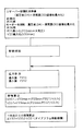
【図2】 本第1実施形態の血液ポンプ駆動装置における制御手順を示すチャート図である。
【図3】 本発明の第2実施形態の血液ポンプ駆動装置を示すブロック図である。
【図4】 本第2実施形態の血液ポンプ駆動装置における制御手順を示すチャート図である。
【図5】 本発明の第3実施形態の血液ポンプ駆動装置を示すブロック図である。
【符号の説明】
10 血液ポンプ
20 オイルポンプ(ポンプ手段)
30 オイルリザーバ
32 液体室(流体室)
33 空気室(気体室)
34 蓄圧室
35 圧力センサ(圧力測定手段) [0001]
BACKGROUND OF THE INVENTION
The present invention drives a blood pump for assisting blood circulation or blood circulation in a living body such as an artificial heart pump or an intra-aortic balloon pump.Blood pump driveRelated to equipment, especially,Detect the pumping pumping capacity of the pulsating blood pump or the stroke displacement of the blood pumpbe able toThe present invention relates to a blood pump drive device.
[0002]
[Prior art]
In a blood pump connected to a living body, the pumping capacity is,For heart recovery and blood circulation resistanceRelationshipDoSoTo know the biological situationImportantBasic information to confirm the correct operation of the blood pumpAlsois there.
[0003]
Also, to get the maximum output with a blood pump,It is desirable to monitor the stroke displacement of the pump to stroke the blood pump full. That is, it is desirable to control so that the blood is pumped out as soon as the blood pump is fully filled, and the blood is sucked out as soon as the blood pump is fully pumped.
[0004]
Can detect pumping capacity and stroke displacement of blood pumpConventional equipmentageThe blood pump and the living bodyWhenThere is one based on a method of measuring a blood flow rate by arranging a flow meter in a pipe connecting the two.
[0005]
Also an exampleFor example, JP-A-6-261872GazetteAs described in 1), there is one based on a method of measuring a displacement of a piston of a blood pump by disposing a position detection device in the blood pump.
[0006]
Or Diagnosis of Mechanical Failures of Total Artificial Hearts (Vol.XXXI Trans
Am Soc Artif Intern Organs 1985 79-81),To measure the amount of air that drives the blood pumpIn, A method of integrating and calculating the air flow rate when opening to the atmosphereBased onwas there.
[0007]
[Problems to be solved by the invention]
In any of the above-mentioned conventional devices, a precise measurement sensor is brought close to the patient, and wiring to a measurement device far from the patient is necessary, so that the activities of the patient must be restricted from the viewpoint of ensuring safety. There was a problem that I could not.
[0008]
Further, in the method shown in the above-mentioned Diagnosis of Mechanical Failures of Total Artificial Hearts, there is a problem that the measurement accuracy and the apparatus become large because it is necessary to integrate the air flow rate.
[0009]
In addition, the blood pumpInBlood pressure loadAs a result, the load is higher than during suction.bigBecomeUnbalanced reciprocal loadIt becomes. for that reasonWhen driving with single motor forward and reverse rotation, the control becomes complicated,Also,power consumptionAlsoBigThere is a problem thatTo reduce the size of the drive unitofDisabilityHad become.
[0010]
The blood pumpAs mentioned aboveWhen you beatThan when suckingSince the blood pressure load is large, there is a problem that the motor rotation speed at the time of stroke becomes very high as compared with that at the time of suction, and the motor rotation speed at the time of stroke reaches a peak and the blood stroke volume does not increase.
[0011]
Therefore, the present inventorFrom the gas chamberThe gas chamber of the oil reservoir having a fluid chamber separated by a movable member;Connect the accumulator chamber andDepending on the pressure accumulation chamberSaidAccumulating the gas pressure in the gas chamber, the fluid filled in the fluid chamber of the oil reservoirBy pump meansDischarge into blood pumpTo letDoAnd the accumulator isIn the suction process of the pump meansThatIt becomes the load of the pump means, and by the pressure stored thereThe discharge process of the pump means,Ie blood pumpAssist the pump means in the stroke processIt will beAs a result of further research and development, the inventors have reached the present invention that achieves the object of eliminating the load imbalance and eliminating the need for a sensor close to the patient.
[0012]
[Means for Solving the Problems]
The blood pump drive device of the present invention (the first invention according to claim 1) includes a gas chamber,From the gas chamberAn oil reservoir having a fluid chamber separated by a movable member;ThatA pump means for discharging the fluid filled in the fluid chamber of the oil reservoir to a blood pump; and the gas chamber of the oil reservoir.Connected and itsA pressure accumulation chamber for accumulating gas pressure in the gas chamber;Pressure measuring means for detecting a gas pressure in the gas chamber of the oil reservoir;WithingIs.
[0013]
The blood pump drive device of the present invention (the second invention according to claim 2) is the first invention.,The pressure measuring means is the pressure accumulation chamber.InAccumulatedspiritTo detect body pressureDisposed in the pressure accumulating chamberIt is what.
[0014]
The present invention (claims)3No. described in3The blood pump drive device of the invention comprises a first port connected to the blood pump, and a gas chamber of the oil reservoirFromConnected to a fluid chamber separated by a movable memberRuPump means for alternately performing the second port and the forward pumping for discharging the fluid sucked from the second port to the first port and the reverse pumping for discharging the fluid sucked from the first port to the second port When,A pressure accumulating chamber connected to the gas chamber of the oil reservoir and accumulating the gas pressure in the gas chamber;The gas chamberInsidePressure measuring means for measuring the pressure of the pump, and a control device for controlling the pumping of the pump means by a signal of the pressure measuring means;,WithingIs.
[0015]
The present invention (claims)4No. described in4(Invention)3In the invention, the control device calculates a discharge amount or a suction amount of fluid to the blood pump based on a change amount of a signal from the pressure measuring means.Have beenIs.
[0016]
The present invention (claims)5No. described in5(Invention)3In the invention, the control device is responsive to a signal from the pressure measuring means,Of the pump meansForward and reverse pumpingWhenTurn offRChangeSupposed to beIs.
[0017]
The present invention (claims)6No. described in6(Invention)3In the invention, the gas chamber is communicated with the atmosphere via a valve means.AndWhen the pressure of the gas chamber becomes negativeThe control device opens the valve means.The gas chamber communicates with the atmosphereIs configured asIs.
[0018]
The present invention (claims)7No. described in7(Invention)3In the invention, the forward pumpingandReverse pumpingEach ofIn the abovePump meansThe volume or pressure of the gas chamber is set so that the load ofHaveIs.
[0019]
The present invention (claims)8No. described in8Invention) blood pump drive device3In the invention, the second fluid chamber andFrom its second fluid chamberA second gas chamber separated by a movable memberHaveA separation chamber, wherein the first port is connected to the second fluid chamber, and the second gas chamber is connected to the blood pump.HaveIs.
[0020]
The present invention (claims)9No. described in9Invention) blood pump drive device8In the invention, the control device is configured to control the second gas chamber based on a signal from the pressure measuring means.gasSet the amountHave beenIs.
[0021]
Operation and effect of the invention
The blood pump drive device of the first invention having the above-described configuration isspiritBody chamber andFlowWith body chamberOhIn the gas chamber of the gas reservoirConnect the pressure accumulator and connect the accumulator to the accumulatorAccumulate gas pressure in the gas chamberLikeBecauseThatThe accumulator isBlood pump suction process, ieOf the oil reservoirFlowBlood pump in the body chamberAspirate fluid fromDoPoIn the suction process of the pump meansThatIt becomes the load of the pump means, and by the pressure stored thereOf blood pumpStroke processThat is, the discharge process of the pump meansInThatIt will serve to assist the pumping means. Therefore,At the time of pumping and aspiration of the blood pumpEliminate load imbalancebe able to,There is an effect.Further, since the gas pressure in the gas chamber of the oil reservoir is detected by the pressure measuring means, control based on the gas pressure can be performed, and the pumping capacity of the blood pump can be calculated, which is close to the patient. There is an effect that the sensor can be omitted.
[0022]
The blood pump drive device according to the second aspect of the present invention having the above-described configuration is the above-described first aspect.,ThatPressure measuring meansTheArranged in accumulatordo it,ThatAccumulated in the accumulatorspiritDetect body pressureLikeSoAccumulationAccumulated in the pressure chamberspiritThere is an effect of enabling control based on body pressure.
[0023]
No. 1 consisting of the above configuration3The blood pump drive device of the invention isSystemThe deviceOil reservoirBy the signal of the pressure measuring means for measuring the pressure of the gas chamber,FirstFluid sucked from 2 portsFirstForward pumping to discharge to 1 portWhenFluid drawn from the first portFirstReverse pumping to discharge to 2 portsWhenAlternatelyPoOf the vehiclePoControlThatMakes the load of forward and reverse rotation of the pump means uniform and eliminates the need for a sensor close to the patientbe able to,There is an effect.
[0024]
No. 1 consisting of the above configuration4The blood pump drive device of the invention is the first3In the invention, the control device is based on a change amount of a signal from the pressure measuring means.And, Calculating the fluid discharge amount or suction amount to the blood pumpLikeSoSoBased on fluid discharge or suction volumeBlood pumpcontrolButPossibleNextFrom the living bodyofAccurate control of blood flow rate and blood discharge rateCanRu,There is an effect.
[0025]
No. 1 consisting of the above configuration5The blood pump drive device of the invention is the first3In the present invention, the control device may perform forward pumping and reverse pumping according to a signal from the pressure measuring means.WhenTurn offRChangeLikeSo the load of forward and reverse rotation of the pump meansAverageEqualizebe able to,There is an effect.
[0026]
No. 1 consisting of the above configuration6The blood pump drive device of the invention is the first3In the invention,Oil reservoirThe gas chamber communicates with the atmosphere via the valve meansAnd,ThatWhen the pressure in the gas chamber becomes negative,The control device opens the valve meansSince the gas chamber communicates with the atmosphere, the pressure of the gas chamber is prevented from being maintained at a negative pressure,gasMaintain proper quantitybe able to,There is an effect.
[0027]
No. 1 consisting of the above configuration7The blood pump drive device of the invention is the first3In the invention, the forward pumping and the reverse pumpingAnd eachSo that the load of the fluid pump in theOil reservoirSince the capacity or pressure of the gas chamber is set, the load on the pump means is equalizedbe able to,There is an effect.
[0028]
No. 1 consisting of the above configuration8The blood pump drive device of the invention is the first3In the invention,FirstWith two fluid chambersFrom its second fluid chamberSeparated by moving partsFirstWith two gas chambersHaveThe separation chamberEstablishmentThe first port isFirstConnected to the second fluid chamber,FirstTwo gas chambersbloodConnected to fluid pumpLikeTherefore, it is possible to use a pneumatically driven blood pump as the blood pumpCanRu,There is an effect.
[0029]
No. 1 consisting of the above configuration9The blood pump drive device of the invention is the first8In the present invention, the control device is based on a signal from the pressure measuring means.AndSet the amount of air in the second gas chamberLikeSo setFirstThere is an effect that control based on the amount of air in the second gas chamber is enabled.
[0030]
DETAILED DESCRIPTION OF THE INVENTION
Embodiments of the present invention will be described below with reference to the drawings.
[0031]
(First embodiment)
As shown in FIG. 1, the blood pump driving apparatus of the first embodiment is,An
[0032]
The
[0033]
Of the oil reservoir
[0034]
The
[0035]
The
[0036]
Blood chamber 12InA
[0037]
The
[0038]
Blood pump drive device of the first embodiment having the above-described configurationofThe operation will be described below using the flowchart shown in FIG.
[0039]
Of the blood pump 10FlowThe body drive
[0040]
The oil pump 20MoDue to the forward rotation of the data 22oilA liquid is sent from the
[0041]
From the above, the pressure accumulationRoomSince the pressure of 34 decreases when the liquid is fed into the
[0042]
[0043]
In addition, thisWhenOf blood pump 10DaA motor whose fluid pressure is about 100 to 200 mmHg so as not to push the
[0044]
Next, the liquid is discharged from the
[0045]
The pressure of the sealed air chamber is P35When, Sealed air chamber capacity V33,Obtained as V33 = V33max × (P35min / P35) ^ (1 / n) from the polytropic change equation.CanThe As described above, P35min is atmospheric pressure, and V33max is known in design in advance.Because, This volume V33 isCalculated as an absolute value. This capacity V33 isoilOf the reservoir 30liquidThe volume of the
[0046]
That is,At this time,Of blood pump
[0047]
When the pumping is started, the
[0048]
Further, when the
[0049]
This maximum threshold isMoThe rotation direction of the
[0050]
This minimum threshold is also,Considering the delay timeThe, Set to a value higher than P35minIsAs a result, the blood pump 10DaSince an excessive force does not act on the
[0051]
In addition, by designing the capacity of the
[0052]
The blood pump drive device according to the first embodiment that exhibits the above-described action is a gas chamber.SkyWith air chamber 33A diaphragm as a movable member from the air chamber 33Separated at 31Liquid as fluid chamberA body chamber 32OhIl reservoir 30SkyIn air chamber 33Connected and itsAccumulate gas pressure in the air chamber 33Accumulation chamber34, soThatThe
[0053]
That is, in the stroke process of the
[0054]
The pressure in the
[0055]
Furthermore, when there is no said
[0056]
In addition, the blood pump drive device of the first embodiment isAs a pressure measuring meanspressureSensor35 of the oil reservoir 30spiritSince the gas pressure in the
[0057]
Furthermore, the blood pump drive device according to the first embodiment provides the pressureSensor35 is the farthest from the patientAccumulationDisposed in the
[0058]
In the blood pump driving device of the first embodiment, the
[0059]
Furthermore, in the blood pump drive device according to the first embodiment, the
[0060]
Further, in the blood pump drive device of the first embodiment, the
[0061]
Furthermore, the blood pump drive device according to the first embodiment includes the gas chamber 33.TheCommunicating with the atmosphere through an on-off
[0062]
Further, the blood pump driving device of the first embodiment includes the forward pumping and the backward pumping.And eachInoilSo that the load of the
[0063]
(Second Embodiment)
The blood pump driving device of the second embodiment is different from the liquid driving blood pump in the first embodiment in that a gas driven blood pump is used as shown in FIG. Hereinafter, the same portions will be described by using the same reference numerals with a focus on the differences.
[0064]
That is, the
[0065]
Gas
[0066]
The
[0067]
At this time, the pressure of the sealed air chamber formed from the
[0068]
At this time, the capacity of the sealed air chamber is calculated from the value of the
[0069]
The
[0070]
If the value of the
[0071]
Furthermore, the forward / reverse rotation of the
[0072]
Next, the moment when the pressure of the
[0073]
Thereby, the pressure of the
[0074]
Of the sealed air chamberDetect pressureWhen the pressure value of the
[0075]
The capacity V33 is a value of the oil reservoir 30.liquidThe volume of the
[0076]
thisWhenBlood pump10ofGas driveThe pressure in the
[0077]
From the above, the pressures P35 and P55 of the two gas chambers during pumping, that is, the pressure sensor 35And pressure sensorFrom the 55 signals, the pulsation capacity of the blood pump is obtained. Blood pump10The control for full filling and full discharge is the same as in the first embodiment.
[0078]
The blood pump drive device of the second embodiment configured as described above
[0079]
Further, in the blood pump drive device of the second embodiment, the
[0080]
(Third embodiment)
In the blood pump drive device of the third embodiment, instead of the
[0081]
In the case where it is guaranteed that no tension is generated in the
[0082]
The blood pump drive device according to the third embodiment has the same effects as those of the first embodiment and the second embodiment described above.Sensor35 of the oil reservoir 30liquidIncompressibility in the body chamber 32FlowbodyofPressurePowerDetected becauseOhIl reservoir 30liquidThe precise control based on the fluid pressure in the
[0083]
Above1st to 3rdThe embodiments are illustrated for illustrative purposes.Yes, The present inventionIsNot limited to themNaIn addition, modifications and additions can be made without departing from the technical idea of the present invention that can be recognized by those skilled in the art from the claims, the detailed description of the invention, and the description of the drawings.
[0084]
In the embodiment described above, the blood pump is applied to an artificial heart pump as an example.Explained aboutBut the present inventionIsNot limited to themNaApplicable to pneumatic aortic balloon pumpsTo doIt can be done.
[Brief description of the drawings]
FIG. 1 is a block diagram showing a blood pump drive device according to a first embodiment of the present invention.
FIG. 2 is a chart showing a control procedure in the blood pump drive device of the first embodiment.
FIG. 3 is a block diagram showing a blood pump drive device according to a second embodiment of the present invention.
FIG. 4 is a chart showing a control procedure in the blood pump drive device of the second embodiment.
FIG. 5 is a block diagram showing a blood pump drive device according to a third embodiment of the present invention.
[Explanation of symbols]
10 Blood pump
20 Oil pump(Pump means)
30 Oil reservoir
32 Liquid chamber(Fluid chamber)
33 Air chamber(Gas chamber)
34 Accumulation chamber
35 Pressure sensor (pressure measuring means)
Claims (9)
そのオイルリザーバの前記流体室に充填された流体を血液ポンプに吐出するポンプ手段と、
前記オイルリザーバの前記気体室に接続されていてその気体室内の気体圧を蓄圧する蓄圧室と、
前記オイルリザーバの前記気体室内の気体圧を検出する圧力測定手段と、
を備えていることを特徴とする血液ポンプ駆動装置。An oil reservoir comprising a gas chamber and a fluid chamber separated from the gas chamber by a movable member;
And pump means for discharging a fluid filled in the fluid chamber of the oil reservoir to the blood pump,
A pressure accumulating chamber connected to the gas chamber of the oil reservoir and accumulating gas pressure in the gas chamber ;
Pressure measuring means for detecting a gas pressure in the gas chamber of the oil reservoir;
Blood pump drive, characterized in that it comprises.
前記圧力測定手段が、前記蓄圧室に蓄圧された気体圧を検出するように、該蓄圧室に配設されていることを特徴とする血液ポンプ駆動装置。 The blood pump drive device according to claim 1 , wherein
The pressure measuring means, to detect the pressure accumulator has been Pneumatic fluid pressure to the accumulator chamber, the blood pump drive, characterized in that disposed on the accumulating chamber.
オイルリザーバの気体室から可動部材で分離された流体室に接続される第2ポートと、
前記第2ポートから吸入した流体を前記第1ポートへ吐出する正方向ポンピングおよび前記第1ポートから吸入した流体を前記第2ポートへ吐出する逆方向ポンピングを交互に行うポンプ手段と、
前記オイルリザーバの前記気体室に接続されてその気体室内の気体圧を蓄圧する蓄圧室と、
前記気体室内の圧力を測定する圧力測定手段と、
前記圧力測定手段の信号により前記ポンプ手段の前記ポンピングを制御する制御装置と、
を備えていることを特徴とする血液ポンプ駆動装置。A first port connected to the blood pump;
A second port from the gas chamber of the oil reservoir Ru is connected to the fluid chamber separated by a movable member,
Pump means for alternately performing forward pumping for discharging fluid sucked from the second port to the first port and reverse pumping for discharging fluid sucked from the first port to the second port;
A pressure accumulating chamber connected to the gas chamber of the oil reservoir and accumulating the gas pressure in the gas chamber;
And pressure measuring means for measuring the pressure in the gas chamber,
A control device for controlling the pumping of the pump means by a signal of the pressure measuring means ;
Blood pump drive, characterized in that it comprises.
前記制御装置が、前記圧力測定手段からの信号の変化量に基づき、前記血液ポンプへの流体の吐出量または吸引量を算出するようにされていることを特徴とする血液ポンプ駆動装置。 The blood pump drive device according to claim 3 , wherein
Wherein the controller, based on said change amount of the signal from the pressure measuring means, the blood pump driving apparatus characterized by being adapted to calculate a discharge amount or suction amount of the fluid into the blood pump.
前記制御装置が、前記圧力測定手段からの信号に応じて、前記ポンプ手段の正方向ポンピングと逆方向ポンピングとを切り換えるものとされていることを特徴とする血液ポンプ駆動装置。 The blood pump drive device according to claim 3 , wherein
Wherein the controller, in response to a signal from said pressure measuring means, that is the forward pumping and backward pumping as the perating the Came ra switching blood pump drive, wherein the pump means.
前記気体室が弁手段を介して大気に連通されており、前記気体室の圧力が負圧になると前記制御装置がその弁手段を開放して前記気体室を大気に連通させるように構成されていることを特徴とする血液ポンプ駆動装置。 The blood pump drive device according to claim 3 , wherein
Said gas chamber is communicated with the atmosphere via a valve means, the gas chamber pressure of the gas chamber becomes a negative pressure and the control device is open the valve means is configured to communicate with the atmosphere blood pump drive, characterized in that there.
前記正方向ポンピングおよび前記逆方向ポンピングのそれぞれにおける前記ポンプ手段の負荷が均等に近づくように、前記気体室の容量または圧力が設定されていることを特徴とする血液ポンプ駆動装置。 The blood pump drive device according to claim 3 , wherein
Wherein as a load of the pump means in each of the forward pumping and the backward pumping approaches evenly, the blood pump driving device according to claim Tei Rukoto capacity or pressure of the gas chamber is set.
第二の流体室とその第二の流体室から可動部材で分離された第二の気体室とを有する分離室を備え、前記第1ポートが前記第二の流体室に接続され、前記第二の気体室が前記血液ポンプに接続されていることを特徴とする血液ポンプ駆動装置。 The blood pump drive device according to claim 3 , wherein
A separation chamber having a second fluid chamber and a second gas chamber separated from the second fluid chamber by a movable member, wherein the first port is connected to the second fluid chamber; blood pump drive unit of the gas chamber and said connected Tei Rukoto in the blood pump.
前記制御装置が、前記圧力測定手段からの信号に基づき、前記第二の気体室の気体量を設定するようにされていることを特徴とする血液ポンプ駆動装置。 The blood pump drive device according to claim 8 , wherein
Wherein the controller, based on said signal from the pressure measuring means, the second blood pump driving apparatus characterized by being adapted to set the amount of gas of the gas chamber.
Priority Applications (2)
| Application Number | Priority Date | Filing Date | Title |
|---|---|---|---|
| JP2000344451A JP4435965B2 (en) | 2000-11-10 | 2000-11-10 | Blood pump drive |
| US09/986,877 US6709383B2 (en) | 2000-11-10 | 2001-11-13 | Device for driving blood pumps |
Applications Claiming Priority (1)
| Application Number | Priority Date | Filing Date | Title |
|---|---|---|---|
| JP2000344451A JP4435965B2 (en) | 2000-11-10 | 2000-11-10 | Blood pump drive |
Publications (2)
| Publication Number | Publication Date |
|---|---|
| JP2002143297A JP2002143297A (en) | 2002-05-21 |
| JP4435965B2 true JP4435965B2 (en) | 2010-03-24 |
Family
ID=18818645
Family Applications (1)
| Application Number | Title | Priority Date | Filing Date |
|---|---|---|---|
| JP2000344451A Expired - Fee Related JP4435965B2 (en) | 2000-11-10 | 2000-11-10 | Blood pump drive |
Country Status (2)
| Country | Link |
|---|---|
| US (1) | US6709383B2 (en) |
| JP (1) | JP4435965B2 (en) |
Families Citing this family (7)
| Publication number | Priority date | Publication date | Assignee | Title |
|---|---|---|---|---|
| US8721515B2 (en) * | 2003-01-31 | 2014-05-13 | L-Vad Technology, Inc. | Rigid body aortic blood pump implant |
| US8540618B2 (en) * | 2003-01-31 | 2013-09-24 | L-Vad Technology, Inc. | Stable aortic blood pump implant |
| DE102006041420A1 (en) * | 2006-09-04 | 2008-03-20 | Bran + Luebbe Gmbh | pump device |
| NL1033204C2 (en) * | 2007-01-10 | 2008-07-11 | Weir Minerals Netherlands Bv | Single-acting displacement device. |
| JP2008230137A (en) * | 2007-03-22 | 2008-10-02 | Fujifilm Corp | Back pressure regulating device of liquid discharge head |
| KR101933062B1 (en) | 2017-09-19 | 2019-03-15 | 서강대학교산학협력단 | Pump with pressure measurement function, fluid transfortation system using the same, and operation method thereof |
| JP2020201175A (en) * | 2019-06-12 | 2020-12-17 | 日機装株式会社 | Pressure detector and blood purifying device using the same |
Family Cites Families (7)
| Publication number | Priority date | Publication date | Assignee | Title |
|---|---|---|---|---|
| US3604016A (en) * | 1969-02-06 | 1971-09-14 | Thermo Electron Corp | Multiple function blood coupler |
| US3680981A (en) * | 1970-12-21 | 1972-08-01 | Josef Wagner | Pump and method of driving same |
| DE2754810C3 (en) * | 1977-12-09 | 1980-12-11 | Dr. Eduard Fresenius Chemisch-Pharmazeutische Industrie Kg Apparatebau Kg, 6380 Bad Homburg | Hemofiltration device |
| JPS60106462A (en) | 1983-11-14 | 1985-06-11 | アイシン精機株式会社 | Drive apparatus of medical machinery |
| CA2004295C (en) * | 1989-11-30 | 1998-02-10 | William F. Hayes | Primary fluid actuated, secondary fluid propelling system |
| US5353646A (en) * | 1994-01-10 | 1994-10-11 | Atlantic Richfield Company | Multiphase fluid flow measurement |
| DE69909274T2 (en) * | 1998-04-06 | 2004-05-27 | Miyawaki, Fujio, Fujimi | MECHANICAL AUXILIARY HEART FOR RESTORING HEART FUNCTION |
-
2000
- 2000-11-10 JP JP2000344451A patent/JP4435965B2/en not_active Expired - Fee Related
-
2001
- 2001-11-13 US US09/986,877 patent/US6709383B2/en not_active Expired - Fee Related
Also Published As
| Publication number | Publication date |
|---|---|
| US6709383B2 (en) | 2004-03-23 |
| US20030069466A1 (en) | 2003-04-10 |
| JP2002143297A (en) | 2002-05-21 |
Similar Documents
| Publication | Publication Date | Title |
|---|---|---|
| EP0472480B1 (en) | A single-needle circuit for circulating blood outside the body in blood treatment apparatus | |
| US4782817A (en) | Ventricular support system | |
| JP4192040B2 (en) | Balloon pump drive device | |
| EP0902689B1 (en) | Pulsatile flow generation in heart-lung machines | |
| JP4435965B2 (en) | Blood pump drive | |
| JPH0516870B2 (en) | ||
| JP6433431B2 (en) | Medical pump | |
| JP4778543B2 (en) | Balloon pump drive device | |
| EP0167562A1 (en) | Implantable heart pump. | |
| WO1997018843A1 (en) | Drive device for medical appliances | |
| JP2002011093A (en) | Artificial pump driving device | |
| RU201911U1 (en) | Blood flow control device for extracorporeal circulatory support systems | |
| US20100121133A1 (en) | Apparatus and methods for measuring pressure and flow in cardiac assist devices and peripheral vasculature | |
| JP2005013502A (en) | Blood pump drive unit | |
| JP2655670B2 (en) | Medical pump drive | |
| CN110709606B (en) | Pressure control device and pressure utilization device | |
| JP2004147721A (en) | Blood pump driver | |
| CN219681473U (en) | Pulse positive and negative pressure power device and saccule counterpulsation system | |
| JPH0622605B2 (en) | Auxiliary artificial heart drive | |
| JPS62155859A (en) | Ultrafiltration amount controller in blood dialyser | |
| RU210252U1 (en) | Blood flow control device in extracorporeal circulatory assist systems | |
| JP2004097611A (en) | Blood pump drive device | |
| SU714046A1 (en) | Perfusion pumping unit | |
| JPS61253068A (en) | Method for driving artificial heart | |
| JPS62172963A (en) | Artificial heart driving apparatus |
Legal Events
| Date | Code | Title | Description |
|---|---|---|---|
| A711 | Notification of change in applicant |
Free format text: JAPANESE INTERMEDIATE CODE: A711 Effective date: 20041122 |
|
| RD02 | Notification of acceptance of power of attorney |
Free format text: JAPANESE INTERMEDIATE CODE: A7422 Effective date: 20041122 |
|
| A621 | Written request for application examination |
Free format text: JAPANESE INTERMEDIATE CODE: A621 Effective date: 20071023 |
|
| A977 | Report on retrieval |
Free format text: JAPANESE INTERMEDIATE CODE: A971007 Effective date: 20090713 |
|
| A131 | Notification of reasons for refusal |
Free format text: JAPANESE INTERMEDIATE CODE: A131 Effective date: 20090804 |
|
| A521 | Request for written amendment filed |
Free format text: JAPANESE INTERMEDIATE CODE: A523 Effective date: 20091005 |
|
| TRDD | Decision of grant or rejection written | ||
| A01 | Written decision to grant a patent or to grant a registration (utility model) |
Free format text: JAPANESE INTERMEDIATE CODE: A01 Effective date: 20091201 |
|
| A01 | Written decision to grant a patent or to grant a registration (utility model) |
Free format text: JAPANESE INTERMEDIATE CODE: A01 |
|
| A61 | First payment of annual fees (during grant procedure) |
Free format text: JAPANESE INTERMEDIATE CODE: A61 Effective date: 20091225 |
|
| R150 | Certificate of patent or registration of utility model |
Free format text: JAPANESE INTERMEDIATE CODE: R150 |
|
| FPAY | Renewal fee payment (event date is renewal date of database) |
Free format text: PAYMENT UNTIL: 20130108 Year of fee payment: 3 |
|
| LAPS | Cancellation because of no payment of annual fees |