JP4435793B2 - Information recording method and information recording apparatus for disc-shaped recording medium - Google Patents
Information recording method and information recording apparatus for disc-shaped recording medium Download PDFInfo
- Publication number
- JP4435793B2 JP4435793B2 JP2007010271A JP2007010271A JP4435793B2 JP 4435793 B2 JP4435793 B2 JP 4435793B2 JP 2007010271 A JP2007010271 A JP 2007010271A JP 2007010271 A JP2007010271 A JP 2007010271A JP 4435793 B2 JP4435793 B2 JP 4435793B2
- Authority
- JP
- Japan
- Prior art keywords
- time
- real
- data
- information recording
- area
- Prior art date
- Legal status (The legal status is an assumption and is not a legal conclusion. Google has not performed a legal analysis and makes no representation as to the accuracy of the status listed.)
- Expired - Fee Related
Links
Images


Description
本発明は、映像や音声等のリアルタイムデータを記録・再生するための書換型光ディスクなどのディスク状情報記録媒体と記録・再生方法及びその情報記録装置と情報再生装置に関する。 The present invention relates to a disc-shaped information recording medium such as a rewritable optical disc for recording / reproducing real-time data such as video and audio, a recording / reproducing method, and the information recording apparatus and information reproducing apparatus.
従来、映像や音声などのリアルタイムデータをディスク上に記録・再生する情報記録媒体として、DVD−RAMがあり、その一例が特許文献1に記載されている。特許文献1の例では、ディスク上の離間したデータに対するリアルタイム再生を保証するために、図8Aに示すような再生標準モデルを定義し、その再生標準モデルに図8Bに示すようなアクセス距離とアクセス時間との関係を規定するアクセス性能モデルを設定した。ここで、再生標準モデルは、種々のタイプの再生機が光ディスク上のリアルタイム・データを再生しても連続して再生が可能な条件を決める目的で作成されたものである。再生標準モデル上でリアルタイムデータを再生するために、図8Bに示すアクセス性能モデルにしたがいバッファメモリ103内のデータがアクセス中にアンダーフローを起こして再生した映像や音声が途切れることのないようなデータの記憶領域を予め設定し、その設定した記憶領域にリアルタイムデータを配置することによりデータの記録を行なう。このように、データの記録を上記のアクセス性能モデルを満たす記憶領域に対して行うことにより、その後再生時にはほぼ上記の標準再生モデルでの設定通りにリアルタイムデータを連続的に再生できるようにする。
Conventionally, there is a DVD-RAM as an information recording medium for recording / reproducing real-time data such as video and audio on / from a disk. In the example of Patent Document 1, a reproduction standard model as shown in FIG. 8A is defined in order to guarantee real-time reproduction with respect to separated data on the disc, and the access distance and access as shown in FIG. 8B are defined in the reproduction standard model. An access performance model that defines the relationship with time was set up. Here, the reproduction standard model is created for the purpose of determining conditions under which various types of reproduction machines can continuously reproduce even when reproducing real-time data on an optical disk. In order to reproduce the real-time data on the reproduction standard model, the data in the
しかしながら、この従来の記録・再生方法では、再生標準モデルにおけるアクセス性能モデルの設定がアクセス距離とアクセス時間の実特性に対して必ずしも精度の高いものでないために、再生時にアクセスタイムのロスが生じてバッファメモリ103のデータがアンダーフローを起こすという課題があった。
However, in this conventional recording / playback method, the access performance model setting in the playback standard model is not necessarily highly accurate with respect to the actual characteristics of the access distance and access time, so access time is lost during playback. There was a problem that data in the
即ち、図8Bに示した従来のアクセス性能モデルは、アクセスする範囲をいくつかの区間に分けて、各区間でアクセス時間が一定となるように、又は距離に比例したアクセス時間となるように構成されていた。しかし、実際のアクセス距離とアクセス時間の関係は非線形な関係を有しており、この従来の再生標準モデルでは、本来有しているアクセス性能に対して低めの設定となるため、現実にアクセスした場合のアクセスタイムに大きなロスを生じていた。 That is, the conventional access performance model shown in FIG. 8B is configured such that the access range is divided into several sections, and the access time is constant in each section, or the access time is proportional to the distance. It had been. However, the relationship between the actual access distance and the access time has a non-linear relationship. In this conventional playback standard model, the access performance is lower than the original access performance. There was a big loss in access time.
本発明は、従来の記録・再生方法の課題に鑑み、アクセス性能モデルの設定の精度を高めることで、効率的なリアルタイム記録を実現することを目的とする。 An object of the present invention is to realize efficient real-time recording by increasing the accuracy of setting an access performance model in view of the problems of conventional recording / reproducing methods.
本発明の第1の態様において、再生標準モデルに従ってリアルタイムデータを再生する場合に、リアルタイムデータが連続して再生されるようにリアルタイムデータを含むリアルタイムファイルをディスク状情報記録媒体に記録する記録方法が提供される。 In the first aspect of the present invention, there is provided a recording method for recording a real-time file including real-time data on a disc-shaped information recording medium so that the real-time data is continuously reproduced when real-time data is reproduced according to the reproduction standard model. Provided.
再生標準モデルはディスク状情報記録媒体からリアルタイムデータを読み出すピックアップと、ピックアップにより読み出されたリアルタイムデータを一時的に保持するバッファメモリと、バッファメモリからリアルタイムデータを読み出して処理する復号モジュールとを含む。再生標準モデルのアクセス性能は次式で与えられる。
Tacc=A・dN+B+f(N)、
ここで、Taccはピックアップが一の領域から他の領域へ移動するのに要する時間であるアクセスタイム、dNはピックアップの移動前と移動後におけるディスク状記録媒体の回転数差、Bは定数であり、Nは加速、減速時の瞬時回転数、f(N)はNの関数である。定数Aは次式で与えられる。
A=J/(Trq・Kj)
Jはディスクのイナーシャ、Trqはモータトルク、Kjは換算定数である。
The reproduction standard model includes a pickup that reads out real-time data from a disc-shaped information recording medium, a buffer memory that temporarily holds real-time data read out by the pickup, and a decoding module that reads out and processes the real-time data from the buffer memory. . The access performance of the playback standard model is given by the following equation.
Tacc = A · dN + B + f (N),
Here, Tacc is an access time which is a time required for the pickup to move from one area to another area, dN is a rotational speed difference of the disk-shaped recording medium before and after the pickup is moved, and B is a constant. , N is the instantaneous rotational speed during acceleration and deceleration, and f (N) is a function of N. The constant A is given by the following equation.
A = J / (Trq · Kj)
J is the inertia of the disk, Trq is the motor torque, and Kj is the conversion constant.
記録方法は、特性データを予め求めて保持するステップと、保持した特性データに基づき再生標準モデルのアクセス性能を求め、ディスク状情報記録媒体内の複数の論理的に連続した未使用領域から、求めた再生標準モデルのアクセス性能に基いて定まる再生時にアンダーフローを生じさせない再生条件であるリアルタイム再生条件を満たす領域をデータ記録用領域として検索するステップと、その検索したデータ記録用領域にリアルタイムデータを記録するステップとを含む。特性データを予め求めて保持するステップは、ディスク状情報記録媒体を所定のトルク値で回転させ、下記式よりJの値を求めるステップと、求めたJの値に基づき定数Aを求め、さらに定数Bを求めるステップと、求めた定数A、Bの値を、ディスク状情報記録媒体を再生する情報記録再生装置のメモリまたはディスク状情報記録媒体に格納するステップとを含む。The recording method obtains characteristic data from a plurality of logically continuous unused areas in the disc-shaped information recording medium by obtaining characteristic data in advance and holding it, obtaining access performance of the reproduction standard model based on the held characteristic data. A step of searching as a data recording area an area that satisfies a real-time playback condition, which is a playback condition that does not cause an underflow at the time of playback determined based on the access performance of the playback standard model, and real-time data is stored in the searched data recording area. Recording. The step of obtaining and holding the characteristic data in advance includes rotating the disc-shaped information recording medium at a predetermined torque value, obtaining a value of J from the following equation, obtaining a constant A based on the obtained value of J, A step of obtaining B, and a step of storing the values of the obtained constants A and B in a memory or a disc-shaped information recording medium of an information recording / reproducing apparatus for reproducing the disc-shaped information recording medium.
J=dt・Kj・Trq/(N1−N2) J = dt.Kj.Trq / (N1-N2)
dtはスピンドルロック時間、N1は初期回転数、N2は目標回転数である。dt is the spindle lock time, N1 is the initial rotation speed, and N2 is the target rotation speed.
本発明の第2の態様において、再生標準モデルに従ってリアルタイムデータを再生する場合に、リアルタイムデータが連続して再生されるようにリアルタイムデータを含むリアルタイムファイルをディスク状情報記録媒体に記録する情報記録装置が提供される。 In the second aspect of the present invention, when reproducing real-time data according to a reproduction standard model, an information recording apparatus for recording a real-time file including real-time data on a disc-shaped information recording medium so that the real-time data is continuously reproduced Is provided.
再生標準モデルはディスク状情報記録媒体からリアルタイムデータを読み出すピックアップと、ピックアップにより読み出されたリアルタイムデータを一時的に保持するバッファメモリと、バッファメモリからリアルタイムデータを読み出して処理する復号モジュールとを含む。再生標準モデルのアクセス性能は次式で与えられる。
Tacc=A・dN+B+f(N)、
ここで、Taccはピックアップが一の領域から他の領域へ移動するのに要する時間であるアクセスタイム、dNはピックアップの移動前と移動後におけるディスク状記録媒体の回転数差、Bは定数であり、Nは加速、減速時の瞬時回転数、f(N)はNの関数である。定数Aは次式で与えられる。
A=J/(Trq・Kj)
Jはディスクのイナーシャ、Trqはモータトルク、Kjは換算定数である。
The reproduction standard model includes a pickup that reads out real-time data from a disc-shaped information recording medium, a buffer memory that temporarily holds real-time data read out by the pickup, and a decoding module that reads out and processes the real-time data from the buffer memory. . The access performance of the playback standard model is given by the following equation.
Tacc = A · dN + B + f (N),
Here, Tacc is an access time which is a time required for the pickup to move from one area to another area, dN is a rotational speed difference of the disk-shaped recording medium before and after the pickup is moved, and B is a constant. , N is the instantaneous rotational speed during acceleration and deceleration, and f (N) is a function of N. The constant A is given by the following equation.
A = J / (Trq · Kj)
J is the inertia of the disk, Trq is the motor torque, and Kj is the conversion constant.
情報記録装置は、特性データを予め求めて保持する手段と、保持した特性データに基づき再生標準モデルのアクセス性能を求め、ディスク状情報記録媒体内の複数の論理的に連続した未使用領域から、求めた再生標準モデルのアクセス性能に基いて定まる再生時にアンダーフローを生じさせない再生条件であるリアルタイム再生条件を満たす領域をデータ記録用領域として検索する検索手段と、その検索したデータ記録用領域にリアルタイムデータを記録する記録手段とを備える。特性データを予め求めて保持する手段は、ディスク状情報記録媒体を所定のトルク値で回転させ、下記式よりJの値を求め、求めたJの値に基づき定数Aを求め、さらに定数Bを求め、求めた定数A、Bの値を、ディスク状情報記録媒体を再生する情報記録再生装置のメモリまたはディスク状情報記録媒体に格納する。The information recording device obtains the characteristic data in advance and holds it, obtains the access performance of the reproduction standard model based on the held characteristic data, and from a plurality of logically continuous unused areas in the disc-shaped information recording medium, Retrieval means for retrieving, as a data recording area, an area that satisfies a real-time reproduction condition, which is a reproduction condition that does not cause underflow during reproduction determined based on the access performance of the obtained reproduction standard model, and real-time in the retrieved data recording area Recording means for recording data. The means for obtaining and holding the characteristic data in advance rotates the disk-shaped information recording medium at a predetermined torque value, obtains the value of J from the following equation, obtains the constant A based on the obtained value of J, and further obtains the constant B. The obtained constants A and B are stored in the memory of the information recording / reproducing apparatus for reproducing the disk-shaped information recording medium or the disk-shaped information recording medium.
J=dt・Kj・Trq/(N1−N2) J = dt.Kj.Trq / (N1-N2)
dtはスピンドルロック時間、N1は初期回転数、N2は目標回転数である。dt is the spindle lock time, N1 is the initial rotation speed, and N2 is the target rotation speed.
本発明によれば、ディスク状情報記録媒体の記録・再生方法及びその情報記録装置と情報再生装置において、アクセス性能モデルの設定に関し、スピンドルモータの特性と回転待ち時間を用い、ピックアップの移動前後のスピンドル回転数差に注目してアクセス性能の式を近似することで、正確なドライブのアクセス動作を容易に見積ることができ、確実なリアルタイム記録を実現するという効果が得られる。 According to the present invention, in the recording / reproducing method of a disk-shaped information recording medium and the information recording apparatus and information reproducing apparatus, the setting of the access performance model is performed using the characteristics of the spindle motor and the rotation waiting time before and after the movement of the pickup. By focusing on the spindle speed difference and approximating the access performance equation, an accurate drive access operation can be easily estimated, and the effect of realizing reliable real-time recording can be obtained.
以下、本発明の実施の形態について図面を参照して説明する。 Hereinafter, embodiments of the present invention will be described with reference to the drawings.
図1(a)は本発明に係る、リアルタイムデータの配置条件を決めるための再生標準モデルを示す図であり、図1(b)はそのアクセス性能を示す図である。図1(a)に示す再生標準モデルは、ディスク101、ディスク101からデータを読み出すピックアップ102、読み出したデータを一時保存するバッファメモリ103、及びバッファメモリ103より転送したデータを復号するための復号モジュール104を含む。Vinはディスク101からバッファメモリ103へデータを転送する時のデータレートである。Voutはバッファメモリ103から復号モジュール104へデータを転送する時のデータレートである。Vinはアプリケーションで想定されるリアルタイムデータの最大データレートVoutよりも大きな値に設置される。
FIG. 1 (a) is a diagram showing a reproduction standard model for determining the arrangement conditions of real-time data according to the present invention, and FIG. 1 (b) is a diagram showing its access performance. The reproduction standard model shown in FIG. 1A includes a
図1(b)は再生標準モデルのピックアップ102がアクセスする時のスピンドルモータの回転数差すなわちディスク回転数差とアクセス時間の関係を示す図である。本実施形態ではCLV(Constant Linear Velocity)方式によりディスク回転数を制御しており、アクセスする領域が半径方向に異なる場合、ディスク回転数が異なることになる。図1(b)においてディスク回転数差とは、ピックアップ102がある領域から別の領域に移動するときの移動前と移動後の回転数差のことである。図1(b)においては、以下に示す前提において後述の式(1)に基づくディスク回転数差とアクセス時間の関係からアクセス性能モデルが設定されている。
FIG. 1B is a diagram showing the relationship between the spindle motor rotation speed difference, that is, the disk rotation speed difference, and the access time when the reproduction
図2(b)に示すようにピックアップ102のアクセスのためには、ピックアップ102をディスク101の半径方向に移動させるシークが必要であり、さらに、図2(a)に示すようにディスクを回転させるスピンドルモータの回転数を目標回転数に変化させることも必要になる。シークには、目標トラック近傍位置までピックアップを移動させる粗シークと、粗シーク後に微調整しピックアップを目標トラック上に移動させるファインシークとがある。図2(b)において粗シークに要する時間はスピンドルモータの回転数の変化に要する時間に比べて十分に小さく設定することが可能であり、光ディスク用ドライブで用いられるスピンドルモータの性能におけるアクセスタイムは、スピンドル回転数変化に要する時間が支配的となる。
As shown in FIG. 2B, in order to access the
一般にモータのトルクTrqは次式で表せる。 In general, the torque Trq of the motor can be expressed by the following equation.
Trq=(N1−N2)・J/(dt・Kj)
J:ディスクのイナーシャ、dt:スピンドルロック時間、Kj:換算定数、N1:移動前の回転数、N2:移動後の回転数。
Trq = (N1-N2) · J / (dt · Kj)
J: inertia of the disk, dt: spindle lock time, Kj: conversion constant, N1: rotational speed before movement, N2: rotational speed after movement.
そこで、スピンドルロック時間が移動前後の回転数の差に比例することに注目して、アクセスタイムTaccは以下の式(1)のように定式化することができる。 Therefore, paying attention to the fact that the spindle lock time is proportional to the difference between the rotational speeds before and after the movement, the access time Tacc can be formulated as the following equation (1).
Tacc=(スピンドルロック時間)+(回転待ち時間)+その他の時間
=(N1−N2)・J/(Trq・Kj)+Trev+B
= A・dN+Trev+B (1)
≒ A・dN+B
但し、N1:初期回転数、N2:目標回転数、dN:回転数差(=N1−N2)、J:ディスクイナーシャ、Trq:モータトルク、Kj:換算定数、Trev:平均回転待ち時間、A、B:定数。
Tacc = (spindle lock time) + (rotation waiting time) + other time = (N1−N2) · J / (Trq · Kj) + Trev + B
= A · dN + Trev + B (1)
≒ A ・ dN + B
Where N1: initial rotational speed, N2: target rotational speed, dN: rotational speed difference (= N1-N2), J: disc inertia, Trq: motor torque, Kj: conversion constant, Trev: average rotational waiting time, A, B: Constant.
なお、式(1)において回転待ち時間Trevはスピンドルロック時間A・dNに比べて十分に小さい場合は省略することもできる。 In the equation (1), the rotation waiting time Trev can be omitted if it is sufficiently smaller than the spindle lock time A · dN.
式(1)で示される関係式に具体的な数値を当てはめると以下のようになる。即ち、N1=3000rpm、N2=1000rpm、dN=2000rpm、J=300gf・cm・cm、Trq=100gf・cm、Kj=9350とすると、A・dN=0.641secとなる。一方、目標回転数N2における平均回転待ち時間Trev=60/1000/2=0.03secとなり、スピンドルロック時間A・dNに比べて十分に小さな値となる。さらに、定数B=0.1とすると、これらを合わせたアクセスタイムはTacc=0.771secとなる。 When specific numerical values are applied to the relational expression represented by the expression (1), the following is obtained. That is, when N1 = 3000 rpm, N2 = 1000 rpm, dN = 2000 rpm, J = 300 gf · cm · cm, Trq = 100 gf · cm, Kj = 9350, A · dN = 0.661 sec. On the other hand, the average rotation waiting time Trev = 60/1000/2 = 0.03 sec at the target rotation speed N2, which is sufficiently smaller than the spindle lock time A · dN. Furthermore, if the constant B = 0.1, the access time combining these becomes Tacc = 0.711 sec.
式(1)から、回転待ち時間Trevが十分に小さい場合には、アクセスタイムTaccはディスクの回転数差dNに対して線形的に推定することができる。このことから、図1(b)に示すようなアクセス性能モデルを想定した。一方、ディスクの回転数並びに回転数差は、ピックアップの初期位置、目標位置がわかると、ディスクの線速度との関係から一意に求めることができる。 From equation (1), when the rotation waiting time Trev is sufficiently small, the access time Tacc can be estimated linearly with respect to the disc rotation speed difference dN. Therefore, an access performance model as shown in FIG. 1B was assumed. On the other hand, if the initial position and target position of the pickup are known, the rotational speed of the disk and the rotational speed difference can be uniquely determined from the relationship with the linear velocity of the disk.
ある領域から別の領域へ移動する際の移動元のアドレスをA1、移動先のアドレスをA2とし、それぞれの半径位置をr1、r2と、アドレスが0の場所での半径位置をr0とすると、アドレスA1、A2は帯状の面積に比例するので、Cを定数として次式で表される。 When moving from one area to another area, the source address is A1, the destination address is A2, the respective radial positions are r1 and r2, and the radial position where the address is 0 is r0. Since the addresses A1 and A2 are proportional to the band-like area, they are expressed by the following equation with C as a constant.
A1=C・(π・r12−π・r02)
A2=C・(π・r22−π・r02)
あるアドレスでの回転数はその半径に反比例するから、A1、A2の回転数をN1,N2、Dを定数として、N1=D/r1、N2=D/r2となるので、上記の関係式を用いる事で、アドレスから回転数を求める事が出来る。
A1 = C · (π · r1 2 −π · r0 2 )
A2 = C · (π · r2 2 −π · r0 2 )
Since the rotational speed at a certain address is inversely proportional to the radius, N1 = D / r1 and N2 = D / r2 where the rotational speeds of A1 and A2 are N1, N2 and D are constants. By using it, the rotation speed can be obtained from the address.
従って、ピックアップの任意の初期位置と目標位置に対して式(1)、即ち、図1(b)で示されるアクセス性能モデルが成り立つ。なお、アクセスの距離が小さい場合、dNが小さくなりTrevが支配的になる。この場合、Trevはピックアップの位置に応じて算出できるので、正確にアクセス性能を求めることができる。 Accordingly, the access performance model shown in Expression (1), that is, FIG. 1B, holds for an arbitrary initial position and target position of the pickup. When the access distance is small, dN becomes small and Trev becomes dominant. In this case, since Trev can be calculated according to the position of the pickup, the access performance can be accurately obtained.
図8Bに示した従来のアクセス性能モデルは、アクセスする範囲をいくつかの区間に分けて、それぞれの区間で一定のアクセス時間もしくは距離に単純に比例するような近似的なアクセス時間に基づいて構成されていたために、本来有しているアクセス性能に対して低めの設定となり、実際のアクセスタイムにおいて大きなロスを生じていたが、本発明のアクセス性能モデルでは、全てのアクセス領域で実際のアクセスモデルに則って精度高くアクセスタイムを求めることができる。 The conventional access performance model shown in FIG. 8B is configured based on an approximate access time that is simply proportional to a certain access time or distance in each section by dividing the access range into several sections. For this reason, the access performance inherently had a low setting and a large loss occurred in the actual access time. However, in the access performance model of the present invention, the actual access model in all access areas. The access time can be obtained with high accuracy according to the above.
次に、図1(a)に示した再生標準モデルにおいて、データを読み出す場合は、バッファメモリ103内には、Vin−Voutのレートでデータが蓄積され、ピックアップ102が移動する場合は、データの読み出しができないために、Voutのレートでバッファ内のデータが消費される。この動作モデルに対し、具体的なアクセス時間の値を用いて、再生標準モデルがリアルタイムデータを再生した場合のバッファメモリ103内のデータ量の推移を定量的に計算することができる。従って、再生標準モデルがリアルタイムデータを再生する時に、バッファメモリ103内のデータがアンダーフローを起こさないようにディスク101上にデータの記録領域が配置されていれば、リアルタイムデータを連続的に再生できることになる。このため、データ記録時においては、上記のアクセス性能モデル基いて、リアルタイムデータが記録されるべき領域(以下「リアルタイムエクステント」という。)の配置条件を規定する。
Next, in the reproduction standard model shown in FIG. 1A, when reading data, the data is accumulated in the
図3A、図3Bを参照し、本実施形態において用いるCLVフォーマットの書換型光ディスクの物理的なレイアウトを説明する。 With reference to FIG. 3A and FIG. 3B, the physical layout of the rewritable optical disk of the CLV format used in this embodiment will be described.
図3Aにおいて、書換型光ディスク101は、内周からリードイン領域401、ディスク上の欠陥セクタを管理するDMA(Defect Management Area)領域402、データ領域420、リードアウト領域412を有する。各領域にはディジタルデータが記録され、ディジタルデータは「セクタ」と称する単位で管理される。データ領域420には、欠陥セクタを代替処理するためのスペア領域403が含まれる。
In FIG. 3A, the rewritable
図3Bに示すように、書換型光ディスク101の情報領域は、内周より、物理セクタ毎に、物理セクタ番号が付与される。これに対し、ユーザーデータが記録可能な領域は、論理セクタ毎に、論理セクタ番号が付与されたボリューム空間として定義される。ボリューム空間は、情報領域から、リードイン領域401、DMA領域402、スペア領域403中の未使用領域、DMA中のPDL(Primary Defective List)に登録された欠陥セクタとリードアウト領域412を除く空間である。
As shown in FIG. 3B, the information area of the rewritable
光ディスク101の初期化時にサーティファイ処理が行われる。このサーティファイ処理により欠陥セクタが検出されると、その欠陥セクタがPDLに登録される。欠陥セクタには論理セクタ番号が割り当てられない。この場合、セクタの論理アドレスが連続していても、物理的に不連続の領域を含むため、この前後の部分にわたって記録・再生する場合には、シークを行う必要がある。なお、データの記録中に検出された欠陥セクタは、スペア領域403に代替されDMA領域402中のSDL(Secondary Defective List)に登録される。
A certification process is performed when the
図4は、本実施形態における書換型光ディスクのさらに詳細なデータ構造を示した図である。 FIG. 4 is a diagram showing a more detailed data structure of the rewritable optical disc in the present embodiment.
図4において、物理セクタから構成される情報領域430は、リードイン領域401、DMA領域402、データ領域420、リードアウト領域412を含む。データ領域420の先頭には欠陥セクタ又は欠陥ブロックを代替記録するためのスペア領域403が配置され、後続する領域よりボリューム空間が形成されている。
In FIG. 4, an information area 430 composed of physical sectors includes a lead-in
データ領域420において、既割付領域405、407、408、409は既にデータが記録されている領域である。リアルタイムエクステントRT1とリアルタイムエクステントRT2の間に欠陥ECCブロック406が形成されている。また、リアルタイムエクステントRT3、RT4、RT5が既割付領域407、408、409に続いてそれぞれ形成されている。欠陥ECCブロック406は、データを記録中に検出された欠陥ブロックであり、本来その欠陥ECCブロックに記録されるべきデータはスペア領域403中に代替記録されている。リアルタイムエクステントRT5の後にエンプティエクステント410と未記録領域411が形成されている。ここで、リアルタイムエクステントRT1〜RT5は、所定のアクセス性能をもつ再生標準モデルにより規定される条件を満たすように配置される。
In the
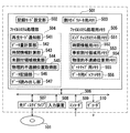
次に、本発明の情報記録再生装置を説明する。図5に情報記録再生装置のブロック構成図を示す。以下、情報記録再生装置による光ディスク101へのリアルタイムファイルの記録動作を説明する。
Next, the information recording / reproducing apparatus of the present invention will be described. FIG. 5 shows a block diagram of the information recording / reproducing apparatus. Hereinafter, the recording operation of the real-time file onto the
情報記録再生装置は、システム制御部501、I/Oバス506、光ディスクドライブ507、記録モード等を入力するためのリモコン、マウス、キーボード等の入力装置508、映像・音声信号をオーディオ・ビデオデータ(AVデータ)に符号化するエンコーダ509、及びAVデータを復号して出力するデコーダ510を含む。
The information recording / reproducing apparatus includes a
システム制御部501は、記録モード設定部502、割付パラメータ用メモリ503、ファイルシステム処理部504、ファイルシステム処理用メモリ505からなる。
The
ファイルシステム処理部504は、再生モード通知部541、データ量計算部542、時間情報計算部543、未割付領域検索部544、物理的不連続位置取得部545、データの記録を制御するデータ記録部546、及びデータの読出しを制御するデータ読み出し部547を含む。これらの手段はファイルシステム処理用メモリ505を利用する。
The file
ファイルシステム処理用メモリ505は、エンプティエクステントの位置情報を格納するメモリ551、時間情報を格納するメモリ552、事前割付領域の位置情報を格納するメモリ553、物理的に不連続な位置を示す位置情報を格納するメモリ554、ビットマップ用メモリ555及びデータ用バッファメモリ556を含む。
The file
光ディスクドライブ507のアクセス性能及びデータ記録時の記録レートとデータ用バッファメモリ556のサイズにより実現されるデータ記録性能が、図1(a)及び図1(b)に示す再生標準モデルを記録に用いた時に実現される記録性能を満たしている。
The data recording performance realized by the access performance of the
以上のように構成された情報記録再生装置は上記の再生標準モデルを満たすよう記録動作を行なう。再生標準モデルは、再生時にバッファメモリ103内のデータがアンダーフローをおこさないようにアクセス性能モデルにしたがってデータの記憶領域(エンプティエクステント/リアルタイムエクステント)を予め設定し、その設定した領域にデータを記録することにより、その後のデータ再生時にリアルタイムデータの連続的な再生を可能とするものである。
The information recording / reproducing apparatus configured as described above performs a recording operation so as to satisfy the reproduction standard model. In the standard reproduction model, a data storage area (empty extent / real-time extent) is set in advance according to the access performance model so that the data in the
以下に、情報記録再生装置の動作を説明する。 The operation of the information recording / reproducing apparatus will be described below.
(ステップ1)入力装置508から記録モード及び記録時間が指示される。記録モード設定部502は、バッファメモリ556からデコーダ510への最大転送データレートVout、ディスク101からの読み出しデータレートVin、記録すべきデータのサイズSR、バッファサイズBmax、その他の各種のアクセス時間を決定し、それらを割付パラメータ用メモリ503へ保持する。ここで、最大データレートVoutは固定値であり、そのレートでの記録が連続しても記録可能となるような値に設定される。
(Step 1) A recording mode and a recording time are instructed from the
(ステップ2)物理的不連続位置取得部545は、ディスク101上の物理的な不連続位置情報として、PDLとSDLに登録された欠陥セクタや欠陥ブロックの位置情報を報告するよう、光ディスクドライブ507に対し指示する。光ディスクドライブ507から報告された物理的な不連続位置情報は物理的不連続位置用メモリ554へ保持される。
(Step 2) The physical discontinuous
未割付領域検索部544は、ビットマップ用メモリ555に保持された未割付領域の位置情報と、物理的不連続位置用メモリ554に保持された物理的な不連続位置情報とを用いて、ECCブロック単位で物理的に連続したディスク上の未割付領域を事前割付領域として検索する。検索した事前割付領域の位置情報は、事前割付領域用メモリ553へ保存される。この検索動作は検索した事前割付領域の合計サイズがデータサイズSRを超えるまで実行される。
The unallocated
図6Aは、上記のような手順によってECCブロック単位で物理的に連続した未割付領域を検索して得られた事前割付領域の配置を示す図である。事前割付領域A1〜A5が割り付けられている。 FIG. 6A is a diagram showing an arrangement of pre-allocated areas obtained by searching unallocated areas that are physically continuous in units of ECC blocks by the procedure as described above. Pre-allocation areas A1 to A5 are allocated.
(ステップ3)時間情報計算部543は、事前割付領域用メモリ553に保存された事前割付領域の位置情報と、割付パラメータ用メモリ503に保存された各種のアクセス時間とを用いて、各事前割付領域をデータレートVinで読み出す時の読み出し時間TRi(iは図6Aに示す事前割付領域の領域番号Aiのiに対応)と、事前割付領域間のアクセス時間Ti,i+1(図6Aに示す事前割付領域AiとAi+1の間のアクセス時間)とを計算する。図6Aにおいて、読み出し時間TR1〜TR5はそれぞれ事前割付領域A1〜A5を読み出すのに要する時間である。また、T1,2は欠陥ECCブロックによる読み出し遅延時間である。T2,3、T3,4、T4,5は、事前割付領域A2とA3、A3とA4、A4とA5の間のそれぞれの既割付領域をアクセスするのに要する時間(アクセス時間)である。これらのアクセス時間は、図1(b)に示した再生標準モデルのアクセス性能より求められる。求められたアクセス時間Ti,i+1は読出し時間TRiとともに時間情報用メモリ552に保持される。
(Step 3) The time
(ステップ4)次に、データ量計算部542は時間情報用メモリ552に保持された読み出し時間とアクセス時間を用いて以下のステップの演算処理を行う。 (Step 4) Next, the data amount calculation unit 542 performs arithmetic processing of the following steps using the read time and access time held in the time information memory 552.
まず事前割付領域の読み出し終了時のバッファメモリ556内のデータ量を計算する。図7は、事前割付領域のデータを読み出した場合のバッファメモリ556内のデータ量の推移を示したものである。例えば、事前割付領域A1を読み出した後の時刻t1において、データ量は期間TR1の間に(Vin−Vout)のデータレートで増加している。
First, the amount of data in the
(ステップ5)計算した事前割付領域のトータルデータ量が、ステップ1で設定したサイズSRを超えるかどうかをチェックする。SRを超えない場合、さらに計算したトータルのデータ量が割付レベルBL(=Vout×TL、TLはフルストロークアクセス時間)を超えるかどうかをチェックする。バッファ内のデータ量がBLを超える場合は、この事前割付領域の終端からディスク上のどの領域にアクセスしてもアンダーフローを起こすことがない。このため、先頭の事前割付領域から、トータルのデータ量がサイズSRを超えず、かつ割付レベルBLを超える事前割付領域までが、アンダーフローを起こさない領域として確定され、これらの領域をリアルタイムデータが記録可能なエンプティエクステントとして登録される。 (Step 5) It is checked whether or not the calculated total data amount of the pre-allocated area exceeds the size SR set in Step 1. If SR is not exceeded, it is further checked whether or not the calculated total data amount exceeds the allocation level BL (= Vout × TL, where TL is the full stroke access time). When the amount of data in the buffer exceeds BL, underflow does not occur when any area on the disk is accessed from the end of this pre-allocated area. For this reason, from the first pre-allocated area to the pre-allocated area where the total data amount does not exceed the size SR and exceeds the allocation level BL is determined as an area that does not cause an underflow, and these areas are stored as real-time data. It is registered as a recordable empty extent.
(ステップ6)次に、事前割付領域の読み出し開始時のバッファメモリ556内のデータ量を計算する。図7の事前割付領域A2を読み出す前の時刻t2において、データ量は期間T1,2においてVoutのデータレートで減少する。
(Step 6) Next, the amount of data in the
(ステップ7)ここで計算したトータルデータ量がマイナスにならないかをチェックする。マイナスになった場合は、このアクセスによりバッファがアンダーフローを起こし、データが中断することを意味する。マイナスにならない場合は、(ステップ4)の先頭に戻る。図6Aにおいて、事前割付領域A2〜A5が(ステップ4)から(ステップ6)を繰り返すことにより計算される。この間に図7に示したTR3、TR4、TR5の各区間でデータ量が割り付けレベルBLを超えるので、図6Aに示すように事前割付領域A1〜A5を順次エンプティエクステントE1〜E5として割り付け、エンプティエクステント用メモリ551にその位置情報を格納する。エンプティエクステントは、リアルタイムデータの記録のために予約された領域ではあるが、未だデータが記録されていない領域である。 (Step 7) It is checked whether the total data amount calculated here is negative. If it becomes negative, this means that the buffer underflows due to this access, and the data is interrupted. If not negative, the process returns to the beginning of (Step 4). In FIG. 6A, the pre-allocated areas A2 to A5 are calculated by repeating (Step 4) to (Step 6). During this time, since the data amount exceeds the allocation level BL in each of the sections TR3, TR4, and TR5 shown in FIG. 7, the pre-allocated areas A1 to A5 are sequentially assigned as empty extents E1 to E5 as shown in FIG. The position information is stored in the memory 551. The empty extent is an area reserved for recording real-time data, but has not yet been recorded with data.
以上のステップで、リアルタイムデータを記録可能な領域(エンプティエクステントE1〜E5)が求められる。 Through the above steps, areas (empty extents E1 to E5) where real-time data can be recorded are obtained.
(ステップ8)次に、情報記録媒体にデータを記録する手順を説明する。情報記録再生装置に入力された映像・音声データがエンコーダ509でAVデータに可変長圧縮方式を用いて符号化されると共に、データ用バッファメモリ556に転送される。データ記録手段546は、既に割り付けたエンプティエクステントE1〜E5にAVデータを記録する。
(Step 8) Next, a procedure for recording data on the information recording medium will be described. The video / audio data input to the information recording / reproducing apparatus is encoded into AV data by the
図6Bに示すように、エンプティエクステントのそれぞれにデータが記録されることにより、エンプティエクステントはそれぞれリアルタイムエクステントになる。エンプティエクステントE1〜E5は、最高の画質・音質に対応可能な固定値のデータレートVoutを用いて割り付けられているために、AVデータの記録完了時には、その一部の領域が未使用状態で残される。即ち、エンプティエクステントE5のうち、データの記録された領域をリアルタイムエクステントRT5とする。また、エンプティエクステントE5のうち、記録するAVデータの終端でECCブロックの一部分のみにAVデータが記録されない領域をエンプティエクステント410とし、ECCブロック単位でAVデータが記録されない領域を未記録領域411とする。
As shown in FIG. 6B, by recording data in each empty extent, each empty extent becomes a real-time extent. Since the empty extents E1 to E5 are allocated using a fixed data rate Vout that can correspond to the highest image quality / sound quality, when AV data recording is completed, a part of the area remains unused. It is. That is, the area where data is recorded in the empty extent E5 is defined as a real-time extent RT5. In the empty extent E5, an area in which AV data is not recorded in only a part of the ECC block at the end of the AV data to be recorded is an
次に、情報記録再生装置による光ディスク101からのリアルタイムファイルの再生動作を説明する。
Next, the reproduction operation of the real-time file from the
光ディスク101にはリアルタイム再生条件を満たした領域にリアルタイムデータが記録されている。データ読出し部547は光ディスク101からリアルタイムデータを読み出す。データ読出し部547は連続してリアルタイムデータを読み出す際に、一のリアルタイムデータをアクセス後、アクセスタイムTacc以内に次のリアルタイムデータへアクセスした後にそのデータを読み出す。読み出されたリアルタイムデータはバッファメモリ556に一時的に格納される。バッファメモリ556に格納されたリアルタイムデータはその後、再生標準モデルにおいて復号モジュールとして規定されるデコーダ510を経由して復号され、映像と音声が再生される。リアルタイム再生条件を満たすように配置されたリアルタイムデータは、規定された性能を満たすので、連続したデータ再生を可能とする。
Real-time data is recorded on the
なお、本発明の実施形態の機能はハードウェアで実現しても良いが、その一部または全体の処理をマイコンのソフトウェアで実施しても良い。 The functions of the embodiment of the present invention may be realized by hardware, but part or all of the processing may be performed by software of a microcomputer.
また、式(1)における定数A、B、Trevといった特性データは、光ディスクドライブ507の基本性能に関わるものである。即ち、定数Aは、スピンドルモータのトルク値Trqを含んでおり、この値は、光ディスクドライブ507のアクセス性能に依存する。また、式(1)における平均回転待ち時間Trevは、光ディスクドライブ507の記録・再生速度が標準速か2倍速かあるいはそれ以上かというドライブ性能によって異なる値となる。さらに定数Bは、例えば、光ディスクドライブ507のインタフェースのコマンド発行に要する時間やECCデコードに要する時間などのドライブ性能に関わるものである。これらの特性データを、例えば、システム制御部501の図示しない不揮発性メモリに予め記憶しておいて、装置ならびにシステム制御部501を起動した際に、前記不揮発性メモリから読み取って、式(1)の演算を行って再生標準モデルを構築してもよい。
The characteristic data such as constants A, B, and Trev in the equation (1) relates to the basic performance of the
なお、式(1)における定数Aは、ディスクのイナーシャJを含んでおり、このイナーシャの値Jは、ディスクの製造公差等によって値がばらつくことがあるので、記録・再生装置にディスクを挿入した際などにディスクを予め決められたトルク値で回転させて、その時に要した時間に基づいて以下の式からその値を推定し、それに基づいて定数Aを求め、さらに定数Bについても予め推定し、これらの特性データをシステム制御部501の図示しない不揮発性メモリに記憶しておくこともできる。
Note that the constant A in the equation (1) includes the inertia J of the disc, and this inertia value J may vary due to disc manufacturing tolerances, etc., so the disc was inserted into the recording / reproducing apparatus. When the disk is rotated at a predetermined torque value, the value is estimated from the following formula based on the time required at that time, the constant A is obtained based on the estimated value, and the constant B is also estimated in advance. These characteristic data can be stored in a nonvolatile memory (not shown) of the
J=dt・Kj・Trq/(N1−N2)
なお、定数A、BやTrevといった特性データをディスクのある特定のエリアに記録しておくこともできる。
J = dt.Kj.Trq / (N1-N2)
It is also possible to record characteristic data such as constants A, B and Trev in a specific area of the disc.
また、上記の特性データに基いてデータ記録された光ディスクを再生する際に、これらの特性データを光ディスクから読み取って、記録再生装置がその光ディスクドライブの性能に対応して予め保持している特性データ値と比較して、ディスクから読み取った特性データの方がドライブ性能を上回る場合は、リアルタイム再生ができないという警告を出すようにしてもよい。所定のアクセスタイムでアクセスできないことによってアンダーフローが発生する恐れがあるからである。 Also, when reproducing an optical disk recorded with data based on the above characteristic data, the characteristic data read from the optical disk and stored in advance by the recording / reproducing apparatus corresponding to the performance of the optical disk drive. If the characteristic data read from the disk exceeds the drive performance as compared with the value, a warning that real-time reproduction cannot be performed may be issued. This is because an underflow may occur due to an inaccessibility at a predetermined access time.
なお、式(1)の導出において、少なくとも、スピンドルモータの加速、減速の制御方式などの詳細な項目は省略して考えたが、正確には、次式で考えてもよく、これによってより高精度にモデル化することができる。 In the derivation of equation (1), at least detailed items such as the spindle motor acceleration and deceleration control methods were omitted, but to be precise, the following equation may be used, and the higher Can be modeled with accuracy.
Tacc=A・dN+B+f(N)
但し、N:加速・減速時の瞬時回転数、f(N):Nの関数。
Tacc = A · dN + B + f (N)
However, N: Instantaneous rotational speed at acceleration / deceleration, f (N): N function.
なお、図2(b)に示した粗シークにおいて、ピックアップの移動を一定加速度での加速領域と、一定速度領域と、一定減速度での減速領域からなる台形状の速度プロファイルに従って、アクセスタイムを見積もることができる場合がある。例えば、加速度及び減速度を0.1G、一定速度を5cm/secとして考えた場合は、アクセスタイムにおいてスピンドルロックに要する時間よりも粗シークに要する時間の方が支配的になる。 In the coarse seek shown in FIG. 2 (b), the access time is set according to a trapezoidal speed profile consisting of an acceleration area at a constant acceleration, a constant speed area, and a deceleration area at a constant deceleration. In some cases, an estimate can be made. For example, when the acceleration and deceleration are assumed to be 0.1 G and the constant speed is assumed to be 5 cm / sec, the time required for the rough seek is more dominant than the time required for the spindle lock in the access time.
なお、図2(b)に示したファインシークにおいて、ピックアップ上に設けたレンズの移動をトラック毎に一定の時間で移動するように見積もってもよいし、またトラック数十本から数百本毎に一定の時間で移動するように見積もってもよい。 In the fine seek shown in FIG. 2 (b), the movement of the lens provided on the pickup may be estimated so as to move in a certain time for each track, or every tens to hundreds of tracks. It may be estimated to move at a certain time.
本発明の光ディスク並びに光ディスクの記録・再生装置及び方法は、正確なドライブのアクセス動作を容易に見積ることができるため、確実なリアルタイム記録を実現でき、光映像や音声等のリアルタイムデータを記録・再生するための書換型光ディスクを記録・再生する方法及び装置に適用できる。 The optical disc and the optical disc recording / reproducing apparatus and method of the present invention can easily estimate an accurate drive access operation, so that real-time recording can be realized reliably, and real-time data such as optical video and audio can be recorded / reproduced. The present invention can be applied to a method and an apparatus for recording / reproducing a rewritable optical disc.
101 光ディスク
103 バッファメモリ
104 復号モジュール
404,411 未記録領域
405,407〜409 既割付領域
410 エンプティエクステント
420 データ領域
430 情報領域
RT1〜RT5 リアルタイムエクステント
101
Claims (2)
前記再生標準モデルは前記ディスク状情報記録媒体から前記リアルタイムデータを読み出すピックアップと、該ピックアップにより読み出されたリアルタイムデータを一時的に保持するバッファメモリと、該バッファメモリからリアルタイムデータを読み出して処理する復号モジュールとを含み、
前記再生標準モデルのアクセス性能が次式で与えられ、
Tacc=A・dN+B+f(N)、
ここで、Taccはピックアップが一の領域から他の領域へ移動するのに要する時間であるアクセスタイム、dNはピックアップの移動前と移動後におけるディスク状記録媒体の回転数差、Bは定数であり、Nは加速、減速時の瞬時回転数、f(N)はNの関数であり、定数Aは次式で与えられ、
A=J/(Trq・Kj)
ここで、Jはディスクのイナーシャ、Trqはモータトルク、Kjは換算定数であり、
前記記録方法は、
特性データを予め求めて保持するステップと、
前記保持した特性データに基づき前記再生標準モデルのアクセス性能を求め、
前記ディスク状情報記録媒体内の複数の論理的に連続した未使用領域から、前記求めた再生標準モデルのアクセス性能に基いて定まる再生時にアンダーフローを生じさせない再生条件であるリアルタイム再生条件を満たす領域をデータ記録用領域として検索するステップと、
その検索したデータ記録用領域にリアルタイムデータを記録するステップとを含み、
前記特性データを予め求めて保持するステップは、
前記ディスク状情報記録媒体を所定のトルク値で回転させ、次式よりJの値を求めるステップと、
J=dt・Kj・Trq/(N1−N2)
ここで、dtはスピンドルロック時間、N1は初期回転数、N2は目標回転数であり、
求めたJの値に基づき定数Aを求め、さらに定数Bを求めるステップと、
求めた定数A、Bの値を、前記ディスク状情報記録媒体を再生する情報記録再生装置のメモリまたは前記ディスク状情報記録媒体に格納するステップとを含む
ことを特徴とするディスク状情報記録媒体の記録方法。 When reproducing real-time data according to a reproduction standard model, a recording method for recording a real-time file including the real-time data on a disc-shaped information recording medium so that the real-time data is continuously reproduced,
The reproduction standard model includes a pickup that reads out the real-time data from the disc-shaped information recording medium, a buffer memory that temporarily holds the real-time data read out by the pickup, and reads and processes the real-time data from the buffer memory. A decryption module,
The access performance of the playback standard model is given by the following equation:
Tacc = A · dN + B + f (N),
Here, Tacc is an access time which is a time required for the pickup to move from one area to another area, dN is a rotational speed difference of the disk-shaped recording medium before and after the pickup is moved, and B is a constant. , N is the instantaneous rotational speed during acceleration and deceleration, f (N) is a function of N, and constant A is given by
A = J / (Trq · Kj)
Where J is the inertia of the disk, Trq is the motor torque, and Kj is the conversion constant.
The recording method is:
Obtaining and holding characteristic data in advance;
Obtaining the access performance of the reproduction standard model based on the retained characteristic data,
An area that satisfies a real-time reproduction condition that is a reproduction condition that does not cause an underflow at the time of reproduction determined based on the access performance of the obtained reproduction standard model from a plurality of logically continuous unused areas in the disc-shaped information recording medium Searching as a data recording area,
Recording real-time data in the retrieved data recording area,
The step of obtaining and holding the characteristic data in advance includes
Rotating the disk-shaped information recording medium at a predetermined torque value, and obtaining a value of J from the following equation:
J = dt.Kj.Trq / (N1-N2)
Here, dt is the spindle lock time, N1 is the initial rotational speed, N2 is the target rotational speed,
Obtaining a constant A based on the obtained value of J, and further obtaining a constant B;
Storing the values of the obtained constants A and B in a memory of an information recording / reproducing apparatus for reproducing the disk-shaped information recording medium or the disk-shaped information recording medium. Recording method.
前記再生標準モデルは前記ディスク状情報記録媒体から前記リアルタイムデータを読み出すピックアップと、該ピックアップにより読み出されたリアルタイムデータを一時的に保持するバッファメモリと、該バッファメモリからリアルタイムデータを読み出して処理する復号モジュールとを含み、前記再生標準モデルのアクセス性能が次式で与えられ、
Tacc=A・dN+B+f(N)、
ここで、Taccはピックアップが一の領域から他の領域へ移動するのに要する時間であるアクセスタイム、dNはピックアップの移動前と移動後におけるディスク状記録媒体の回転数差、Bは定数であり、Nは加速、減速時の瞬時回転数、f(N)はNの関数であり、定数Aは次式で与えられ、
A=J/(Trq・Kj)
ここで、Jはディスクのイナーシャ、Trqはモータトルク、Kjは換算定数であり、
前記記録装置は、
特性データを予め求めて保持する手段と、
前記保持した特性データに基づき前記再生標準モデルのアクセス性能を求め、前記ディスク状情報記録媒体内の複数の論理的に連続した未使用領域から、前記求めた再生標準モデルのアクセス性能に基いて定まる再生時にアンダーフローを生じさせない再生条件であるリアルタイム再生条件を満たす領域をデータ記録用領域として検索する検索手段と、
その検索したデータ記録用領域にリアルタイムデータを記録する記録手段とを備え、
前記特性データを予め求めて保持する手段は、
前記ディスク状情報記録媒体を所定のトルク値で回転させ、次式よりJの値を求め、
J=dt・Kj・Trq/(N1−N2)
ここで、dtはスピンドルロック時間、N1は初期回転数、N2は目標回転数であり、
求めたJの値に基づき定数Aを求め、さらに定数Bを求め、求めた定数A、Bの値を、前記ディスク状情報記録媒体を再生する情報記録再生装置のメモリまたは前記ディスク状情報記録媒体に格納する
ことを特徴とする情報記録装置。 When reproducing real-time data according to a reproduction standard model, an information recording apparatus for recording a real-time file including the real-time data on a disc-shaped information recording medium so that the real-time data is continuously reproduced,
The reproduction standard model includes a pickup that reads out the real-time data from the disc-shaped information recording medium, a buffer memory that temporarily holds the real-time data read out by the pickup, and reads and processes the real-time data from the buffer memory. An access performance of the reproduction standard model is given by the following equation:
Tacc = A · dN + B + f (N),
Here, Tacc is an access time which is a time required for the pickup to move from one area to another area, dN is a rotational speed difference of the disk-shaped recording medium before and after the pickup is moved, and B is a constant. , N is the instantaneous rotational speed during acceleration and deceleration, f (N) is a function of N, and constant A is given by
A = J / (Trq · Kj)
Where J is the inertia of the disk, Trq is the motor torque, and Kj is the conversion constant.
The recording device comprises:
Means for obtaining and holding characteristic data in advance;
The access performance of the reproduction standard model is obtained based on the held characteristic data, and is determined based on the obtained access performance of the reproduction standard model from a plurality of logically continuous unused areas in the disc-shaped information recording medium. A search means for searching, as a data recording area, an area that satisfies a real-time playback condition that is a playback condition that does not cause underflow during playback;
Recording means for recording real-time data in the retrieved data recording area,
Means for obtaining and holding the characteristic data in advance,
The disk-shaped information recording medium is rotated at a predetermined torque value, and the value of J is obtained from the following equation:
J = dt.Kj.Trq / (N1-N2)
Here, dt is the spindle lock time, N1 is the initial rotational speed, N2 is the target rotational speed,
A constant A is obtained based on the obtained J value, a constant B is further obtained, and the obtained constants A and B are used as the memory of the information recording / reproducing apparatus for reproducing the disc information recording medium or the disc information recording medium. An information recording apparatus characterized by being stored in
Priority Applications (1)
| Application Number | Priority Date | Filing Date | Title |
|---|---|---|---|
| JP2007010271A JP4435793B2 (en) | 2002-08-08 | 2007-01-19 | Information recording method and information recording apparatus for disc-shaped recording medium |
Applications Claiming Priority (2)
| Application Number | Priority Date | Filing Date | Title |
|---|---|---|---|
| JP2002231385 | 2002-08-08 | ||
| JP2007010271A JP4435793B2 (en) | 2002-08-08 | 2007-01-19 | Information recording method and information recording apparatus for disc-shaped recording medium |
Related Parent Applications (1)
| Application Number | Title | Priority Date | Filing Date |
|---|---|---|---|
| JP2003285057A Division JP2004087102A (en) | 2002-08-08 | 2003-08-01 | Disk-like information recording medium, its recording method and reproduction method, and its information recording device and information reproducing device |
Publications (3)
| Publication Number | Publication Date |
|---|---|
| JP2007149335A JP2007149335A (en) | 2007-06-14 |
| JP2007149335A5 JP2007149335A5 (en) | 2008-01-17 |
| JP4435793B2 true JP4435793B2 (en) | 2010-03-24 |
Family
ID=38210524
Family Applications (1)
| Application Number | Title | Priority Date | Filing Date |
|---|---|---|---|
| JP2007010271A Expired - Fee Related JP4435793B2 (en) | 2002-08-08 | 2007-01-19 | Information recording method and information recording apparatus for disc-shaped recording medium |
Country Status (1)
| Country | Link |
|---|---|
| JP (1) | JP4435793B2 (en) |
-
2007
- 2007-01-19 JP JP2007010271A patent/JP4435793B2/en not_active Expired - Fee Related
Also Published As
| Publication number | Publication date |
|---|---|
| JP2007149335A (en) | 2007-06-14 |
Similar Documents
| Publication | Publication Date | Title |
|---|---|---|
| EP1150293B1 (en) | Method for recording and reproducing in real time | |
| US7286751B2 (en) | Recording medium for storing real time recording/reproduction information, method and apparatus for recording and reproducing in real time, and file operating method using the same | |
| US7065671B2 (en) | Information processor, information processing method and medium recording information processing method | |
| JP4083651B2 (en) | Information recording method and information recording apparatus | |
| US7848184B2 (en) | Reproducing method for reproducing real time data from a disk-shaped information recording medium | |
| US7603520B2 (en) | Record apparatus, record method, and program for writing data to optical disc in a second unit larger than a first unit | |
| KR20070040402A (en) | Managing data space on a record carrier | |
| JP4435793B2 (en) | Information recording method and information recording apparatus for disc-shaped recording medium | |
| US7983123B2 (en) | Methods of defect management and reproduction, program and recording medium, and apparatuses for information recording and information reproduction | |
| JP4027726B2 (en) | Information recording / reproducing apparatus, information recording / reproducing method, program, recording medium, and information recording / reproducing system | |
| US20060221804A1 (en) | Optical recording medium and defect management device and method therefor | |
| JP4504979B2 (en) | Information storage device and method | |
| JP2008503847A (en) | Managing defects at the file level | |
| JP2004087102A (en) | Disk-like information recording medium, its recording method and reproduction method, and its information recording device and information reproducing device | |
| JP2006120200A (en) | Recording device, recording method, program, and recording medium | |
| JP2007519136A (en) | Information recording apparatus and method with reconstruction of defect management information | |
| JP2007519137A (en) | Information recording apparatus and method | |
| JP3927091B2 (en) | Information recording / reproducing apparatus, information recording / reproducing method, program, and recording medium | |
| JP2001052436A (en) | Recorder | |
| JP2001282588A (en) | File management device | |
| JP4651603B2 (en) | Information recording / reproducing device | |
| JP2001067805A (en) | Recording apparatus | |
| JP2006309924A (en) | Optical recording medium and defect management device and method for optical recording medium | |
| JP2008176921A (en) | Recording device | |
| JP2008176922A (en) | Recording device |
Legal Events
| Date | Code | Title | Description |
|---|---|---|---|
| A521 | Written amendment |
Free format text: JAPANESE INTERMEDIATE CODE: A523 Effective date: 20071126 |
|
| A977 | Report on retrieval |
Free format text: JAPANESE INTERMEDIATE CODE: A971007 Effective date: 20090827 |
|
| A131 | Notification of reasons for refusal |
Free format text: JAPANESE INTERMEDIATE CODE: A131 Effective date: 20090908 |
|
| A521 | Written amendment |
Free format text: JAPANESE INTERMEDIATE CODE: A523 Effective date: 20091104 |
|
| TRDD | Decision of grant or rejection written | ||
| A01 | Written decision to grant a patent or to grant a registration (utility model) |
Free format text: JAPANESE INTERMEDIATE CODE: A01 Effective date: 20091124 |
|
| A01 | Written decision to grant a patent or to grant a registration (utility model) |
Free format text: JAPANESE INTERMEDIATE CODE: A01 |
|
| A61 | First payment of annual fees (during grant procedure) |
Free format text: JAPANESE INTERMEDIATE CODE: A61 Effective date: 20091224 |
|
| R150 | Certificate of patent or registration of utility model |
Free format text: JAPANESE INTERMEDIATE CODE: R150 |
|
| FPAY | Renewal fee payment (event date is renewal date of database) |
Free format text: PAYMENT UNTIL: 20130108 Year of fee payment: 3 |
|
| FPAY | Renewal fee payment (event date is renewal date of database) |
Free format text: PAYMENT UNTIL: 20140108 Year of fee payment: 4 |
|
| LAPS | Cancellation because of no payment of annual fees |