JP4435249B2 - Power transmission component and damper mechanism including the same - Google Patents

Power transmission component and damper mechanism including the same Download PDF

Info

Publication number
JP4435249B2
JP4435249B2 JP2008191516A JP2008191516A JP4435249B2 JP 4435249 B2 JP4435249 B2 JP 4435249B2 JP 2008191516 A JP2008191516 A JP 2008191516A JP 2008191516 A JP2008191516 A JP 2008191516A JP 4435249 B2 JP4435249 B2 JP 4435249B2
Authority
JP
Japan
Prior art keywords
flywheel
power transmission
protrusion
main body
spring
Prior art date
Legal status (The legal status is an assumption and is not a legal conclusion. Google has not performed a legal analysis and makes no representation as to the accuracy of the status listed.)
Active
Application number
JP2008191516A
Other languages
Japanese (ja)
Other versions
JP2010031885A (en
Inventor
恒三 山本
啓介 藤岡
共希 羽田
Current Assignee (The listed assignees may be inaccurate. Google has not performed a legal analysis and makes no representation or warranty as to the accuracy of the list.)
Exedy Corp
Original Assignee
Exedy Corp
Priority date (The priority date is an assumption and is not a legal conclusion. Google has not performed a legal analysis and makes no representation as to the accuracy of the date listed.)
Filing date
Publication date
Priority to JP2008191516A priority Critical patent/JP4435249B2/en
Application filed by Exedy Corp filed Critical Exedy Corp
Priority to DE112009001678T priority patent/DE112009001678T5/en
Priority to US12/996,594 priority patent/US8840481B2/en
Priority to DE112009005528.1T priority patent/DE112009005528B4/en
Priority to DE112009005530.3T priority patent/DE112009005530B4/en
Priority to PCT/JP2009/063105 priority patent/WO2010010896A1/en
Priority to CN2009801280793A priority patent/CN102089548B/en
Publication of JP2010031885A publication Critical patent/JP2010031885A/en
Application granted granted Critical
Publication of JP4435249B2 publication Critical patent/JP4435249B2/en
Active legal-status Critical Current
Anticipated expiration legal-status Critical

Links

Images

Description

本発明は、動力伝達部品、特に、回転動力を伝達するための動力伝達部品に関する。   The present invention relates to a power transmission component, and more particularly to a power transmission component for transmitting rotational power.

エンジンで発生した動力を伝達するために、車両の駆動系には様々な装置が搭載されている。この種の装置としては、例えばクラッチ装置やフライホイール組立体が考えられる。これらの装置には、回転振動の減衰を目的として、ダンパー機構が用いられている(例えば、特許文献1および2を参照)。   In order to transmit the power generated by the engine, various devices are mounted on the drive system of the vehicle. As this type of device, for example, a clutch device or a flywheel assembly can be considered. In these devices, a damper mechanism is used for the purpose of damping rotational vibration (see, for example, Patent Documents 1 and 2).

特開平7−208547号公報Japanese Unexamined Patent Publication No. 7-208547 特開平9−242825号公報JP-A-9-242825

この種のダンパー機構は、例えば、入力部材と、出力部材と、入力部材と出力部材とを回転方向に弾性的に連結する複数のスプリングと、スプリングの端部を支持するスプリングシートと、を有している。この場合、入力部材および出力部材が動力伝達部品である。   This type of damper mechanism has, for example, an input member, an output member, a plurality of springs that elastically connect the input member and the output member in the rotational direction, and a spring seat that supports the end of the spring. is doing. In this case, the input member and the output member are power transmission components.

このダンパー機構では、入力部材に動力が伝達されると、入力部材が出力部材に対して回転を開始する。この結果、入力部材と出力部材との間でスプリングが圧縮されて、回転振動が減衰される。   In this damper mechanism, when power is transmitted to the input member, the input member starts rotating with respect to the output member. As a result, the spring is compressed between the input member and the output member, and the rotational vibration is attenuated.

しかし、従来の動力伝達部品では、例えば、入力部材とスプリングシートとの接触面積が小さい場合は、面圧が大きくなるため樹脂製のスプリングシートが損耗しやすい。また、接触面積を大きく確保すると、入力部材の重量が増大するため好ましくない。   However, in the conventional power transmission component, for example, when the contact area between the input member and the spring seat is small, the surface pressure increases, and the resin spring seat is likely to be worn out. In addition, securing a large contact area is not preferable because the weight of the input member increases.

本発明の課題は、重量の増大を抑制しつつ動力伝達面積を大きく確保できる動力伝達部品およびダンパー機構を提供することにある。   An object of the present invention is to provide a power transmission component and a damper mechanism that can ensure a large power transmission area while suppressing an increase in weight.

本発明に係る動力伝達部品は、回転動力を伝達するための部品であって、環状の本体部と、プレート状の伝達部と、を備えている。本体部には、回転動力が入力または出力される。伝達部は、本体部から半径方向外側へ延びる第1突出部と、第1突出部の円周方向の端部から軸方向の第1側に延び回転動力を伝達する第2突出部と、を有している。第2突出部は、半径方向に延びる第1部分と、第2部分と、を有している。第2部分は、第1部分の半径方向内側の端部と本体部の外周部とを連結し軸方向から見た場合に湾曲している。 The power transmission component according to the present invention is a component for transmitting rotational power, and includes an annular main body portion and a plate-shaped transmission portion. Rotational power is input to or output from the main body. The transmission portion includes a first protrusion that extends radially outward from the main body, and a second protrusion that extends from the circumferential end of the first protrusion to the first side in the axial direction and transmits rotational power. Have. The second protrusion has a first portion extending in the radial direction and a second portion. The second portion is curved when the end portion on the radially inner side of the first portion and the outer peripheral portion of the main body portion are connected and viewed from the axial direction.

この動力伝達部品では、第2突出部が第1突出部の円周方向の端部から軸方向の第1側へ延びているため、例えば第2突出部の動力伝達面積を大きく確保することができる。それに加えて、伝達部がプレート状であるため、動力伝達部品の重量が増大するのを抑制できる。   In this power transmission component, since the second protrusion extends from the circumferential end of the first protrusion to the first side in the axial direction, for example, a large power transmission area of the second protrusion can be ensured. it can. In addition, since the transmission portion is plate-shaped, it is possible to suppress an increase in the weight of the power transmission component.

また、この動力伝達部品では、第2部分によって第1部分の半径方向内側の端部と本体部の外周部が連結されているため、伝達部全体の強度が高まる。さらに、第2部分が軸方向から見た場合に湾曲しているため、第2部分に応力集中が生じにくくなり、第2突出部の破損を抑制できる。  Moreover, in this power transmission component, since the end portion on the radially inner side of the first portion and the outer peripheral portion of the main body portion are connected by the second portion, the strength of the entire transmission portion is increased. Furthermore, since the second portion is curved when viewed from the axial direction, stress concentration is less likely to occur in the second portion, and damage to the second protrusion can be suppressed.

本発明に係る動力伝達部品およびダンパー機構では、重量の増大を抑制しつつ動力伝達面積を大きく確保することができる。   In the power transmission component and the damper mechanism according to the present invention, a large power transmission area can be secured while suppressing an increase in weight.

フライホイール組立体の平面図Top view of flywheel assembly 図1のII−II断面図II-II sectional view of FIG. フライホイール組立体の平面図Top view of flywheel assembly フライホイール組立体の平面図Top view of flywheel assembly 図3のV−V断面図V-V sectional view of FIG. 図4のVI−VI断面図VI-VI sectional view of FIG. (A)第1スプリングシートの平面図、(B)第1スプリングシートの断面図(A) Plan view of the first spring seat, (B) Cross section of the first spring seat (A)第2スプリングシートの平面図、(B)第2スプリングシートの断面図(A) Plan view of the second spring seat, (B) Cross section of the second spring seat 図3のIX−IX断面図IX-IX sectional view of FIG.

<全体構成>
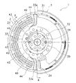
図1〜図9を用いてフライホイール組立体1について説明する。図2、図5および図6の左側にはエンジン(図示せず)が配置されており、右側にはトランスミッション(図示せず)が配置されている。以後、図2、図5および図6において左側をエンジン側(軸方向第1側の一例)といい、右側をトランスミッション側という。
<Overall configuration>
The flywheel assembly 1 will be described with reference to FIGS. 2, 5 and 6, an engine (not shown) is arranged on the left side, and a transmission (not shown) is arranged on the right side. Hereinafter, the left side in FIGS. 2, 5, and 6 is referred to as the engine side (an example of the first axial direction), and the right side is referred to as the transmission side.

図1に示すように、フライホイール組立体1は、エンジンで発生した動力をクラッチ装置(図示せず)を介してトランスミッションに伝達するための装置である。フライホイール組立体1は、第1フライホイール2(第1回転体の一例)と、第2フライホイール3(第2回転体の一例)と、ダンパー機構4と、摩擦発生機構5と、を備えている。   As shown in FIG. 1, the flywheel assembly 1 is a device for transmitting power generated by an engine to a transmission via a clutch device (not shown). The flywheel assembly 1 includes a first flywheel 2 (an example of a first rotating body), a second flywheel 3 (an example of a second rotating body), a damper mechanism 4, and a friction generating mechanism 5. ing.

<第1フライホイール>
第1フライホイール2は、エンジンで発生した動力が入力される部材であり、ボルト28によりエンジンのクランクシャフト(図示せず)に固定されている。第1フライホイール2は、第1プレート21と、第2プレート22と、支持部材23と、押さえプレート26と、を有している。
<First flywheel>
The first flywheel 2 is a member to which power generated by the engine is input, and is fixed to a crankshaft (not shown) of the engine by a bolt 28. The first flywheel 2 has a first plate 21, a second plate 22, a support member 23, and a pressing plate 26.

第1プレート21は、第1プレート本体21aと、2つの第1側方部21bと、第1プレート本体21aおよび第1側方部21bの外周部から軸方向に延びる筒状部21cと、を有している。   The first plate 21 includes a first plate body 21a, two first side parts 21b, and a cylindrical part 21c extending in the axial direction from the outer periphery of the first plate body 21a and the first side part 21b. Have.

第1側方部21bは、第1プレート本体21aよりもエンジン側に迫り出した部分であり、例えばプレス加工により成形されている。2つの第1側方部21bは、回転方向に等ピッチで配置されている。第1側方部21bは、4つのスプリングセット49(後述)に対応する範囲に形成されている。第1側方部21bの内周部には、軸方向に対して傾斜する傾斜面21e(第1傾斜面の一例)が形成されている。傾斜面21eは第1スプリングシート44の第1傾斜摺動面44d(後述)および第2スプリングシート43の第2傾斜摺動面43d(後述)と摺動可能である。   The 1st side part 21b is a part which protruded to the engine side rather than the 1st plate main body 21a, for example, is shape | molded by press work. The two first side portions 21b are arranged at an equal pitch in the rotation direction. The first side portion 21b is formed in a range corresponding to four spring sets 49 (described later). An inclined surface 21e (an example of a first inclined surface) that is inclined with respect to the axial direction is formed on the inner peripheral portion of the first side portion 21b. The inclined surface 21e is slidable with a first inclined sliding surface 44d (described later) of the first spring seat 44 and a second inclined sliding surface 43d (described later) of the second spring seat 43.

第2プレート22は、筒状部21cに固定された環状の部材であり、第2プレート本体22aと、2つの第2側方部22bと、内側筒状部22cと、複数の支持突起22dと、複数の凹部22fと、を有している。   The second plate 22 is an annular member fixed to the cylindrical portion 21c, and includes a second plate body 22a, two second side portions 22b, an inner cylindrical portion 22c, and a plurality of support protrusions 22d. And a plurality of recesses 22f.

第2側方部22bは、第2プレート本体22aよりもトランスミッション側に迫り出した部分であり、例えばプレス加工により成形されている。2つの第2側方部22bは、回転方向に等ピッチで配置されている。第2側方部22bは、4つのスプリングセット49(後述)に対応する範囲に形成されている。第2側方部22bの内周部には、軸方向に対して傾斜する傾斜面22e(第1傾斜面の一例)が形成されている。傾斜面22eは、傾斜面21eと対をなす面であり、第1スプリングシート44の第1傾斜摺動面44d(後述)および第2スプリングシート43の第2傾斜摺動面43d(後述)と摺動可能である。   The 2nd side part 22b is a part which protruded to the transmission side rather than the 2nd plate main body 22a, for example, is shape | molded by press work. The two second side portions 22b are arranged at an equal pitch in the rotation direction. The second side portion 22b is formed in a range corresponding to four spring sets 49 (described later). An inclined surface 22e (an example of a first inclined surface) that is inclined with respect to the axial direction is formed on the inner peripheral portion of the second side portion 22b. The inclined surface 22e is a surface that forms a pair with the inclined surface 21e, and includes a first inclined sliding surface 44d (described later) of the first spring seat 44 and a second inclined sliding surface 43d (described later) of the second spring seat 43. It is slidable.

第2側方部22bは第1側方部21bと軸方向に向かい合って配置されているため、第1フライホイール2の外周部にスプリングセット49が配置される比較的広い空間を第1側方部21bおよび第2側方部22bにより形成することができる。また、図9に示すように、第1側方部21bの回転方向の端部および第2側方部22bの回転方向の端部は第1スプリングシート44を回転方向に当接可能であるため、第1側方部21bおよび第2側方部22bにより第1スプリングシート44は、回転方向に支持されている。第1フライホイール2において第1スプリングシート44を回転方向に支持している部分を支持部2aとする。   Since the second side portion 22b is disposed so as to face the first side portion 21b in the axial direction, a relatively wide space in which the spring set 49 is disposed on the outer peripheral portion of the first flywheel 2 is provided in the first side portion. 21b and the second side portion 22b. Further, as shown in FIG. 9, the end of the first side portion 21b in the rotation direction and the end of the second side portion 22b in the rotation direction can contact the first spring seat 44 in the rotation direction. The first spring seat 44 is supported in the rotational direction by the first side portion 21b and the second side portion 22b. A portion of the first flywheel 2 that supports the first spring seat 44 in the rotation direction is referred to as a support portion 2a.

支持突起22dは、第2側方部22bからトランスミッション側に突出しており、例えばエンボス加工により形成されている。支持突起22dの加工に伴い、支持突起22dの軸方向の反対側にはトランスミッション側に窪んだ凹部22fが形成される。複数の支持突起22dは円周方向に等ピッチで配置されており、複数の凹部22fも円周方向の等ピッチで配置されている。内側筒状部22cは、第2プレート本体22aの内周部からエンジン側に延びる筒状の部分であり、シールリング38(後述)と接触している。   The support protrusion 22d protrudes from the second side portion 22b to the transmission side, and is formed by, for example, embossing. Along with the processing of the support protrusion 22d, a recess 22f recessed toward the transmission is formed on the opposite side of the support protrusion 22d in the axial direction. The plurality of support protrusions 22d are arranged at an equal pitch in the circumferential direction, and the plurality of recesses 22f are also arranged at an equal pitch in the circumferential direction. The inner cylindrical portion 22c is a cylindrical portion extending from the inner peripheral portion of the second plate main body 22a to the engine side, and is in contact with a seal ring 38 (described later).

支持部材23は、環状の支持部材本体23aと、環状突起23bと、環状の摺動部23cと、を有している。支持部材本体23aは、第1プレート21とともにボルト28によりクランクシャフトに固定されている。環状突起23bは、支持部材本体23aの内周部からエンジン側に突出する環状の部分であり、第1プレート21の半径方向の位置決めを行っている。摺動部23cは、支持部材本体23aから半径方向に延びる部分であり、摩擦発生機構5の第2ブッシュ55と摺動する。支持部材本体23aの外周部にはベアリング39が嵌め込まれている。   The support member 23 includes an annular support member main body 23a, an annular protrusion 23b, and an annular sliding portion 23c. The support member main body 23 a is fixed to the crankshaft by bolts 28 together with the first plate 21. The annular protrusion 23b is an annular portion that protrudes from the inner peripheral portion of the support member main body 23a toward the engine, and positions the first plate 21 in the radial direction. The sliding portion 23 c is a portion extending in the radial direction from the support member main body 23 a and slides with the second bush 55 of the friction generating mechanism 5. A bearing 39 is fitted on the outer periphery of the support member main body 23a.

押さえプレート26は、ベアリング39を軸方向に押さえるための部材であり、第1プレート21および支持部材23とともにボルト28によりクランクシャフトに固定されている。   The pressing plate 26 is a member for pressing the bearing 39 in the axial direction, and is fixed to the crankshaft by bolts 28 together with the first plate 21 and the support member 23.

<第2フライホイール>
第2フライホイール3は、第1フライホイール2に対して回転可能に配置された部材であり、第2フライホイール本体31と、出力プレート33(動力伝達部品の一例)と、を有している。第2フライホイール3はベアリング39により第1フライホイール2に対して回転可能なように支持されている。
<Second flywheel>
The 2nd flywheel 3 is a member arranged so that rotation to the 1st flywheel 2 is carried out, and has the 2nd flywheel main part 31 and output plate 33 (an example of power transmission parts). . The second flywheel 3 is supported by a bearing 39 so as to be rotatable with respect to the first flywheel 2.

第2フライホイール本体31は、第2プレート22のトランスミッション側に配置された環状の部材であり、支持部31aと、摩擦部31bと、を有している。   The second flywheel main body 31 is an annular member disposed on the transmission side of the second plate 22 and includes a support portion 31a and a friction portion 31b.

支持部31aは、ベアリング39により第1フライホイール2に対して回転可能に支持された環状の部分であり、第2プレート22の内周側に配置されている。支持部31aの溝31cにはシールリング38が嵌め込まれている。シールリング38により第1フライホイール2の収容空間Sと第1フライホイール2の外部の空間とがシールされている。収容空間Sには潤滑油が充填されている。支持部31aにはリベット32により出力プレート33が固定されている。   The support portion 31 a is an annular portion that is rotatably supported by the bearing 39 with respect to the first flywheel 2, and is disposed on the inner peripheral side of the second plate 22. A seal ring 38 is fitted in the groove 31c of the support portion 31a. The housing space S of the first flywheel 2 and the space outside the first flywheel 2 are sealed by the seal ring 38. The accommodation space S is filled with lubricating oil. An output plate 33 is fixed to the support portion 31 a by rivets 32.

摩擦部31bは、クラッチディスク組立体の摩擦フェーシング(図示せず)が押し付けられる環状の部分であり、支持部31aの外周部に設けられている。摩擦部31bは、第2プレート22のトランスミッション側に配置されており、支持部31aよりもトランスミッション側に迫り出している。   The friction portion 31b is an annular portion to which a friction facing (not shown) of the clutch disk assembly is pressed, and is provided on the outer peripheral portion of the support portion 31a. The friction part 31b is disposed on the transmission side of the second plate 22, and protrudes closer to the transmission side than the support part 31a.

出力プレート33は、収容空間S内に配置されており、支持部31aに固定されている。出力プレート33は、環状の本体部33aと、本体部33aから半径方向に延びる2つの伝達部33eと、を有している。   The output plate 33 is arrange | positioned in the accommodation space S, and is being fixed to the support part 31a. The output plate 33 has an annular main body portion 33a and two transmission portions 33e extending in the radial direction from the main body portion 33a.

本体部33aは支持部31aに固定された環状の部分である。本体部33aの内周部には、円周方向に等ピッチで配置された複数の切欠き33dが形成されている。切欠き33dには第2摩擦プレート52の突起52b(後述)が挿入されている。これにより、第2摩擦プレート52と第2フライホイール3とは一体回転可能となっている。   The main body portion 33a is an annular portion fixed to the support portion 31a. A plurality of notches 33d arranged at equal pitches in the circumferential direction are formed in the inner peripheral portion of the main body portion 33a. A protrusion 52b (described later) of the second friction plate 52 is inserted into the notch 33d. Thereby, the 2nd friction plate 52 and the 2nd flywheel 3 can rotate integrally.

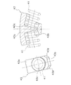
伝達部33eは、第1フライホイール2に伝達された動力が4つのスプリングセット49を介して伝達される部分であり、第1突出部33cと、1対の第2突出部33bと、を有している。第1突出部33cおよび第2突出部33bは、例えばプレス加工により成形されている。   The transmission portion 33e is a portion to which the power transmitted to the first flywheel 2 is transmitted through the four spring sets 49, and includes a first protrusion 33c and a pair of second protrusions 33b. ing. The 1st protrusion part 33c and the 2nd protrusion part 33b are shape | molded, for example by press work.

第1突出部33cは、本体部33aから半径方向外側に突出する板状の部分である。第1突出部33cは、本体部33aと同じ軸方向位置に配置された中央部33h(第1突出部本体の一例)と、中央部33hよりも軸方向トランスミッション側に迫り出すように形成された1対の外側部33iと、を有している。1対の外側部33iは、中央部33hの回転方向の両側に配置されている。   The first protruding portion 33c is a plate-like portion that protrudes radially outward from the main body portion 33a. The first protruding portion 33c is formed so as to protrude toward the axial transmission side from the central portion 33h (an example of the first protruding portion main body) disposed at the same axial position as the main body portion 33a. And a pair of outer portions 33i. The pair of outer portions 33i are disposed on both sides in the rotation direction of the central portion 33h.

第2突出部33bは、第1突出部33c(より詳細には、外側部33i)の回転方向の端部から軸方向エンジン側に延びる部分であり、当接部33fと、補強部33gと、を有している。当接部33fは、半径方向に延びる部分であり、第1スプリングシート44(後述)と回転方向に当接可能な当接面33j(伝達面の一例)を有している。当接部33fの厚み方向(当接面33jの法線方向)は回転方向と概ね一致している。補強部33gは、当接部33fの半径方向内側の端部と本体部33aの外周部とを連結する部分であり、当接部33fの半径方向内側の端部から当接面33jが向いている側に延びている。図3および図4に示すように、補強部33gは湾曲する部分を有している。補強部33gの軸方向寸法は、当接部33fの軸方向寸法と同じである。外側部33iが中央部33hよりもトランスミッション側に迫り出しているため、当接部33fの軸方向寸法Lを比較的大きく確保できる。これにより、当接面33jの面積を大きく設定できる。特に、当接部33fと第1スプリングシート44との接触面積が250mm以上に確保されている。 The second projecting portion 33b is a portion extending from the rotational end of the first projecting portion 33c (more specifically, the outer portion 33i) to the axial engine side, and includes a contact portion 33f, a reinforcing portion 33g, have. The contact portion 33f is a portion extending in the radial direction, and includes a first spring seat 44 (described later) and a contact surface 33j (an example of a transmission surface) capable of contacting in the rotation direction. The thickness direction of the contact portion 33f (the normal direction of the contact surface 33j) is substantially coincident with the rotation direction. The reinforcing portion 33g is a portion that connects the radially inner end portion of the contact portion 33f and the outer peripheral portion of the main body portion 33a, and the contact surface 33j faces from the radially inner end portion of the contact portion 33f. It extends to the side. As shown in FIGS. 3 and 4, the reinforcing portion 33g has a curved portion. The axial dimension of the reinforcing part 33g is the same as the axial dimension of the contact part 33f. Since the outer portion 33i protrudes closer to the transmission side than the central portion 33h, the axial dimension L of the abutting portion 33f can be secured relatively large. Thereby, the area of the contact surface 33j can be set large. In particular, the contact area between the contact portion 33f and the first spring seat 44 is ensured to be 250 mm 2 or more.

<ダンパー機構>
ダンパー機構4は、第1フライホイール2と第2フライホイール3とを回転方向に弾性的に連結する機構であり、8つのスプリングセット49と、4つの第1スプリングシート44と、6つの第2スプリングシート43と、を有している。ダンパー機構4には、前述の第1プレート21、第2プレート22および出力プレート33も含まれている。
<Damper mechanism>
The damper mechanism 4 is a mechanism that elastically connects the first flywheel 2 and the second flywheel 3 in the rotational direction, and includes eight spring sets 49, four first spring seats 44, and six second springs. And a sheet 43. The damper mechanism 4 also includes the first plate 21, the second plate 22, and the output plate 33 described above.

スプリングセット49は、第1スプリング41と、第2スプリング42と、を有している。第1スプリング41の内側に第2スプリング42が並列に作用するように配置されている。第1側方部21b、第2側方部22bおよび筒状部21cにより形成された第1収容部B1には、4つのスプリングセット49が予め圧縮された状態で直列に作用するように配置されている。この状態では、スプリングセット49と伝達部33eとの間に配置された第1スプリングシート44が、第1側方部21bの回転方向の端部(回転方向端部の一例)および第2側方部22bの回転方向の端部(回転方向端部の一例)と回転方向に当接している。 The spring set 49 includes a first spring 41 and a second spring 42. A second spring 42 is arranged inside the first spring 41 so as to act in parallel. Four spring sets 49 are arranged in the first compressed portion B1 formed by the first side portion 21b, the second side portion 22b, and the tubular portion 21c so as to act in series in a pre-compressed state. Yes. In this state, the first spring seat 44 disposed between the spring set 49 and the transmission portion 33e includes the end portion in the rotation direction of the first side portion 21b (an example of the end portion in the rotation direction) and the second side portion. 22b is in contact with the rotation direction end (an example of the rotation direction end) in the rotation direction.

具体的には、第1スプリングシート44は、第1シート本体44cと、第1外側支持部44aと、第1内側支持部44bと、を有している。第1シート本体44cはスプリングセット49の端部を回転方向に支持している。第1外側支持部44aは、第1シート本体44cの半径方向外側部分から回転方向に延びる部分であり、スプリングセット49の端部を半径方向に支持している。第1外側支持部44aは第1プレート21の筒状部21cと摺動可能である。   Specifically, the first spring seat 44 includes a first seat body 44c, a first outer support portion 44a, and a first inner support portion 44b. The first seat body 44c supports the end of the spring set 49 in the rotational direction. The first outer support portion 44a is a portion extending in the rotational direction from the radially outer portion of the first seat body 44c, and supports the end portion of the spring set 49 in the radial direction. The first outer support portion 44 a is slidable with the cylindrical portion 21 c of the first plate 21.

第1内側支持部44bは、第1シート本体44cの半径方向内側部分から回転方向に延びる部分であり、スプリングセット49の端部を半径方向に支持している。第1内側支持部44bおよび第1外側支持部44aにより、スプリングセット49の端部は半径方向だけでなく軸方向にも支持されている。   The first inner support portion 44b is a portion extending in the rotational direction from the radially inner portion of the first seat body 44c, and supports the end portion of the spring set 49 in the radial direction. The end portions of the spring set 49 are supported not only in the radial direction but also in the axial direction by the first inner support portion 44b and the first outer support portion 44a.

第1内側支持部44bは、第1外側支持部44aよりも回転方向の長さが短い。第1内側支持部44bは、第1内側支持部44bの軸方向両側に対称となるように配置された1対の第1傾斜摺動面44d(第2傾斜面の一例)を有している。第1傾斜摺動面44dは、軸方向および半径方向に対して傾斜しており、第1内側支持部44bの回転方向全体にわたって形成されている。例えば、第1傾斜摺動面44dは回転軸に対して約45度だけ傾斜している。第1傾斜摺動面44dは傾斜面21eと摺動可能である。   The first inner support portion 44b is shorter in the rotation direction than the first outer support portion 44a. The first inner support portion 44b has a pair of first inclined sliding surfaces 44d (an example of a second inclined surface) disposed so as to be symmetrical on both axial sides of the first inner support portion 44b. . The first inclined sliding surface 44d is inclined with respect to the axial direction and the radial direction, and is formed over the entire rotational direction of the first inner support portion 44b. For example, the first inclined sliding surface 44d is inclined by about 45 degrees with respect to the rotation axis. The first inclined sliding surface 44d is slidable with the inclined surface 21e.

スプリングセット49同士の間には第2スプリングシート43が配置されている。第2スプリングシート43は、第2シート本体43cと、第2外側支持部43aと、第2内側支持部43bと、を有している。第2シート本体43cはスプリングセット49の端部を回転方向に支持している。第2シート本体43cはスプリングセット49の端部を回転方向に支持している。第2外側支持部43aは、第2シート本体43cの半径方向外側部分から回転方向両側に延びる部分であり、スプリングセット49の端部を半径方向に支持している。第2外側支持部43aは筒状部21cと摺動可能である。   A second spring seat 43 is disposed between the spring sets 49. The second spring seat 43 includes a second seat body 43c, a second outer support portion 43a, and a second inner support portion 43b. The second sheet body 43c supports the end of the spring set 49 in the rotational direction. The second sheet body 43c supports the end of the spring set 49 in the rotational direction. The second outer support portion 43a is a portion that extends from the radially outer portion of the second seat body 43c to both sides in the rotational direction, and supports the end of the spring set 49 in the radial direction. The second outer support portion 43a is slidable with the cylindrical portion 21c.

第2内側支持部43bは、第2シート本体43cの半径方向内側部分から回転方向両側に延びる部分であり、スプリングセット49の端部を半径方向に支持している。第2内側支持部43bおよび第2外側支持部43aにより、スプリングセット49の端部は半径方向だけでなく軸方向にも支持されている。   The second inner support portion 43b is a portion extending from the radially inner portion of the second seat body 43c to both sides in the rotational direction, and supports the end portion of the spring set 49 in the radial direction. The end portions of the spring set 49 are supported not only in the radial direction but also in the axial direction by the second inner support portion 43b and the second outer support portion 43a.

第2内側支持部43bは、第2外側支持部43aよりも回転方向の長さが短い。第2内側支持部43bは、第2内側支持部43bの軸方向両側に対称となるように配置された1対の第2傾斜摺動面43d(第2傾斜面の一例)を有している。第2傾斜摺動面43dは、軸方向および半径方向に対して傾斜しており、第2内側支持部43bの回転方向全体にわたって形成されている。例えば、第2傾斜摺動面43dは回転軸に対して約45度だけ傾斜している。第2傾斜摺動面43dは傾斜面21eと摺動可能である。   The second inner support portion 43b is shorter in the rotation direction than the second outer support portion 43a. The second inner support portion 43b has a pair of second inclined sliding surfaces 43d (an example of a second inclined surface) disposed so as to be symmetrical on both axial sides of the second inner support portion 43b. . The second inclined sliding surface 43d is inclined with respect to the axial direction and the radial direction, and is formed over the entire rotational direction of the second inner support portion 43b. For example, the second inclined sliding surface 43d is inclined by about 45 degrees with respect to the rotation axis. The second inclined sliding surface 43d is slidable with the inclined surface 21e.

スプリングセット49、第1スプリングシート44および第2スプリングシート43は、第1フライホイール2の収容空間Sに収容されている。具体的には、第1側方部21b、筒状部21cおよび第2側方部22bにより形成される第1収容部B1内に、スプリングセット49、第1スプリングシート44および第2スプリングシート43は配置されている。第1収容部B1よりも軸方向に絞られた第2収容部B2には、前述の1対の傾斜面21eが形成されている。このため、第1スプリングシート44および第2スプリングシート43は、第1フライホイール2に対する軸方向および半径方向の移動が規制された状態で、第1収容部B1内を回転方向に移動可能となっている。   The spring set 49, the first spring seat 44 and the second spring seat 43 are accommodated in the accommodating space S of the first flywheel 2. Specifically, the spring set 49, the first spring seat 44, and the second spring seat 43 are in the first housing portion B1 formed by the first side portion 21b, the cylindrical portion 21c, and the second side portion 22b. Has been placed. The above-described pair of inclined surfaces 21e is formed in the second housing portion B2 that is narrower in the axial direction than the first housing portion B1. For this reason, the first spring seat 44 and the second spring seat 43 can move in the first accommodating portion B1 in the rotational direction in a state where movement in the axial direction and the radial direction with respect to the first flywheel 2 is restricted. ing.

<摩擦発生機構>
摩擦発生機構5は、第1フライホイール2と第2フライホイール3との間で回転方向の抵抗力を発生させるための機構であり、第1摩擦プレート53と、第2摩擦プレート52と、第1ブッシュ54と、第2ブッシュ55と、コーンスプリング51と、を有している。
<Friction generating mechanism>
The friction generating mechanism 5 is a mechanism for generating a rotational force between the first flywheel 2 and the second flywheel 3, and includes a first friction plate 53, a second friction plate 52, The first bush 54, the second bush 55, and the cone spring 51 are provided.

第1摩擦プレート53は、第1フライホイール2と一体回転可能に配置されており、第1ブッシュ54のエンジン側に配置されている。   The first friction plate 53 is disposed so as to be able to rotate integrally with the first flywheel 2 and is disposed on the engine side of the first bush 54.

第2摩擦プレート52は、第2フライホイール3と一体回転可能に配置されており、環状のプレート本体52a(第1部材本体の一例)と、プレート本体52aから半径方向外側へ突出した複数の突起52bと、を有している。プレート本体52aは、第1ブッシュ54および第2ブッシュ55の軸方向間に配置されており、第1ブッシュ54および第2ブッシュ55と摺動可能である。突起52bは前述の切欠き33dに挿入されている。   The second friction plate 52 is disposed so as to be rotatable integrally with the second flywheel 3, and has an annular plate body 52 a (an example of a first member body) and a plurality of protrusions protruding radially outward from the plate body 52 a. 52b. The plate body 52 a is disposed between the first bush 54 and the second bush 55 in the axial direction, and is slidable with the first bush 54 and the second bush 55. The protrusion 52b is inserted into the aforementioned notch 33d.

第1ブッシュ54は、第1摩擦プレート53と第2摩擦プレート52との軸方向間に挟み込まれており、第1フライホイール2および第2フライホイール3に対して回転可能に配置されている。第2ブッシュ55は、第2摩擦プレート52と摺動部23cとの軸方向間に挟み込まれており、第2摩擦プレート52および第1フライホイール2に対して回転可能に配置されている。コーンスプリング51は、第1摩擦プレート53と第1プレート21との軸方向間に配置されており、第1摩擦プレート53をトランスミッション側に押圧している。   The first bush 54 is sandwiched between the first friction plate 53 and the second friction plate 52 in the axial direction, and is disposed so as to be rotatable with respect to the first flywheel 2 and the second flywheel 3. The second bush 55 is sandwiched between the second friction plate 52 and the sliding portion 23 c in the axial direction, and is disposed so as to be rotatable with respect to the second friction plate 52 and the first flywheel 2. The cone spring 51 is disposed between the first friction plate 53 and the first plate 21 in the axial direction, and presses the first friction plate 53 toward the transmission side.

<動作>
クラッチディスク組立体が第2フライホイール3に押し付けられると、エンジンからトランスミッションへフライホイール組立体1およびクラッチディスク組立体を介して動力が伝達される。具体的には、第2フライホイール3に対して第1フライホイール2が回転方向の駆動側に回転し始める。この結果、第1フライホイール2と第2フライホイール3との間でスプリングセット49の圧縮が開始される。より詳細には、第1フライホイール2と第2フライホイール3の伝達部33eとの間で回転方向にスプリングセット49が圧縮される。このとき、スプリングセット49の端部が第1スプリングシート44および第2スプリングシート43により覆われているため、スプリングセット49の端部が第1フライホイール2と摺動するのを防止できる。
<Operation>
When the clutch disk assembly is pressed against the second flywheel 3, power is transmitted from the engine to the transmission via the flywheel assembly 1 and the clutch disk assembly. Specifically, the first flywheel 2 starts to rotate to the drive side in the rotational direction with respect to the second flywheel 3. As a result, the compression of the spring set 49 is started between the first flywheel 2 and the second flywheel 3. More specifically, the spring set 49 is compressed in the rotational direction between the first flywheel 2 and the transmission portion 33e of the second flywheel 3. At this time, since the end portion of the spring set 49 is covered with the first spring seat 44 and the second spring seat 43, the end portion of the spring set 49 can be prevented from sliding with the first flywheel 2.

また、第2フライホイール3に対して第1フライホイール2が回転すると、摩擦発生機構5において摩擦抵抗が発生する。具体的には、第1摩擦プレート53に対して第2摩擦プレート52が回転するため、第1ブッシュ54が第1摩擦プレート53または第2摩擦プレート52と摺動する。また、第2摩擦プレート52に対して支持部材23の摺動部23cが回転するため、第2ブッシュ55が第2摩擦プレート52または摺動部23cと摺動する。したがって、第1フライホイール2および第2フライホイール3の間で回転方向の抵抗(つまり、ヒステリシストルク)が発生する。   Further, when the first flywheel 2 rotates with respect to the second flywheel 3, a frictional resistance is generated in the friction generating mechanism 5. Specifically, since the second friction plate 52 rotates with respect to the first friction plate 53, the first bush 54 slides with the first friction plate 53 or the second friction plate 52. Further, since the sliding portion 23c of the support member 23 rotates with respect to the second friction plate 52, the second bush 55 slides with the second friction plate 52 or the sliding portion 23c. Therefore, resistance in the rotational direction (that is, hysteresis torque) is generated between the first flywheel 2 and the second flywheel 3.

第2フライホイール3に対する第1フライホイール2の回転が進行すると、第1スプリングシート44の第1外側支持部44aと第2スプリングシート43の第2外側支持部43aとが回転方向に当接する。この結果、第1フライホイール2の支持部2aと伝達部33eとの回転方向間に第1スプリングシート44および第2スプリングシート43が挟まれ、第1フライホイール2および第2フライホイール3の相対回転が停止する。これにより、第1フライホイール2から第2フライホイール3へ第1スプリングシート44および第2スプリングシート43を介して動力が伝達される。   When the rotation of the first flywheel 2 relative to the second flywheel 3 proceeds, the first outer support portion 44a of the first spring seat 44 and the second outer support portion 43a of the second spring seat 43 abut in the rotation direction. As a result, the first spring seat 44 and the second spring seat 43 are sandwiched between the rotation directions of the support portion 2a and the transmission portion 33e of the first flywheel 2, and the relative relationship between the first flywheel 2 and the second flywheel 3 is reached. The rotation stops. Thereby, power is transmitted from the first flywheel 2 to the second flywheel 3 via the first spring seat 44 and the second spring seat 43.

<特徴>
以上に説明したフライホイール組立体1の特徴を以下にまとめる。
<Features>
The characteristics of the flywheel assembly 1 described above are summarized below.

(1−1)
この出力プレート33では、第2突出部33bが第1突出部33cの円周方向の端部から軸方向エンジンへ延びているため、例えば第2突出部33bの当接面33jの面積を大きく確保することができる。これにより、第2突出部33bの損耗あるいは第2突出部33bと当接する第1スプリングシート44の損耗を低減できる。
(1-1)
In this output plate 33, since the second protrusion 33b extends from the circumferential end of the first protrusion 33c to the axial engine, for example, a large area of the contact surface 33j of the second protrusion 33b is ensured. can do. Thereby, the wear of the 2nd protrusion part 33b or the wear of the 1st spring seat 44 contact | abutted with the 2nd protrusion part 33b can be reduced.

(1−2)
この出力プレート33では、補強部33gにより当接部33fと本体部33aとが連結されているため、伝達部33e全体の強度を高めることができる。
(1-2)
In this output plate 33, since the contact portion 33f and the main body portion 33a are connected by the reinforcing portion 33g, the strength of the entire transmission portion 33e can be increased.

(1−3)
この出力プレート33では、補強部33gが湾曲しているため、補強部33gに応力集中が生じにくくなり、第2突出部33bの破損を抑制できる。
(1-3)
In the output plate 33, since the reinforcing portion 33g is curved, it is difficult for stress concentration to occur in the reinforcing portion 33g, and damage to the second protruding portion 33b can be suppressed.

(1−4)
この出力プレート33では、当接面33jの向いている側に補強部33gが延びているため、伝達部33eにより動力が伝達される際に、圧縮力ではなく引っ張り力が補強部33gに作用しやすくなる。これにより、突出部および伝達部33e全体の強度をさらに高めることができる。
(1-4)
In the output plate 33, since the reinforcing portion 33g extends to the side facing the contact surface 33j, when power is transmitted by the transmitting portion 33e, a tensile force acts on the reinforcing portion 33g instead of a compressive force. It becomes easy. Thereby, the intensity | strength of the protrusion part and the transmission part 33e whole can further be raised.

(1−5)
この出力プレート33では、当接部33fの厚み方向が回転方向と概ね一致しているため、大きな動力伝達面を確保しやすい。
(1-5)
In the output plate 33, since the thickness direction of the contact portion 33f substantially coincides with the rotation direction, it is easy to secure a large power transmission surface.

(1−6)
この出力プレート33では、第1突出部33cの外側部33iが中央部33hよりも軸方向トランスミッション側に迫り出しているため、外側部33iの端部から軸方向エンジン側へ延びる第2突出部33bの軸方向寸法を大きく確保することができる。つまり、伝達部33eの当接面33jの面積をさらに大きく確保することができる。
(1-6)
In the output plate 33, since the outer portion 33i of the first protruding portion 33c protrudes toward the axial transmission side with respect to the central portion 33h, the second protruding portion 33b extending from the end portion of the outer portion 33i to the axial engine side. A large axial dimension can be secured. That is, the area of the contact surface 33j of the transmission portion 33e can be further increased.

(1−7)
このように、フライホイール組立体1では、出力プレート33が用いられているため、動力伝達面積を大きく確保することができ、第1スプリングシート44の損耗を低減できる。
(1-7)
Thus, since the output plate 33 is used in the flywheel assembly 1, a large power transmission area can be secured and wear of the first spring seat 44 can be reduced.

(2−1)
このダンパー機構4では、第1摩擦プレート53と第2摩擦プレート52との軸方向間に第1ブッシュ54が挟み込まれており、かつ、第1摩擦プレート53と第2フライホイール3との軸方向間に第2ブッシュ55が挟み込まれているため、摩擦面を増やすことができる。これにより、ダンパー機構の振動減衰性能を高めることができる。
(2-1)
In the damper mechanism 4, the first bushing 54 is sandwiched between the axial directions of the first friction plate 53 and the second friction plate 52, and the axial direction of the first friction plate 53 and the second flywheel 3. Since the second bush 55 is sandwiched between them, the friction surface can be increased. Thereby, the vibration damping performance of the damper mechanism can be enhanced.

(2−2)
このダンパー機構4では、出力プレート33の切欠き33dに第2摩擦プレート52の突起52bが挿入されているため、第2摩擦プレート52が第2フライホイール3と一体回転する構成を簡素な構造により実現できる。
(2-2)
In this damper mechanism 4, since the protrusion 52 b of the second friction plate 52 is inserted into the notch 33 d of the output plate 33, the configuration in which the second friction plate 52 rotates integrally with the second flywheel 3 is simplified. realizable.

(2−3)
このダンパー機構4では、支持部材23の摺動部23cが出力プレート33の本体部33aの半径方向内側に配置されているため、第2摩擦プレート52と摺動部23cとの軸方向間に第2ブッシュ55を挟み込む構成を簡素な構造により実現できる。
(2-3)
In this damper mechanism 4, since the sliding portion 23 c of the support member 23 is disposed on the radially inner side of the main body portion 33 a of the output plate 33, the second friction plate 52 and the sliding portion 23 c are arranged between the axial directions. The configuration for sandwiching the two bushes 55 can be realized with a simple structure.

(3−1)
この出力プレート33では、第2プレート22が複数の支持突起22dを有しているため、第2プレート22に対するリングギヤ29の位置決めを容易に行うことができる。つまり、第2プレート22に支持突起22dを形成するだけでリングギヤ29の位置決めを行うことができ、製造コストの低減を図ることができる。
(3-1)
In the output plate 33, since the second plate 22 has a plurality of support protrusions 22d, the ring gear 29 can be easily positioned with respect to the second plate 22. That is, the ring gear 29 can be positioned simply by forming the support protrusion 22d on the second plate 22, and the manufacturing cost can be reduced.

(3−2)
この出力プレート33では、支持突起22dがリングギヤ29の半径方向内側に入り込んでいるため、支持突起22dにより第2プレート22の軸方向寸法が大きくなるのを防止できる。
(3-2)
In the output plate 33, since the support protrusion 22d enters the inside of the ring gear 29 in the radial direction, it is possible to prevent the axial dimension of the second plate 22 from being increased by the support protrusion 22d.

(3−3)
この出力プレート33では、隣り合う支持突起22dの円周方向間に溶接部29aが配置されているため、小さなスペースでリングギヤ29の位置決めおよび固定を行うことができる。
(3-3)
In this output plate 33, since the welded portion 29a is disposed between the circumferential directions of the adjacent support protrusions 22d, the ring gear 29 can be positioned and fixed in a small space.

(3−4)
この出力プレート33では、第2プレート22が支持突起22dのエンジン側に配置された凹部22fを有しているため、支持突起22dによる重量の増加を低減できる。
(3-4)
In the output plate 33, since the second plate 22 has the recess 22f arranged on the engine side of the support protrusion 22d, an increase in weight due to the support protrusion 22d can be reduced.

(3−5)
このように、このフライホイール組立体1では、出力プレート33を第2フライホイール3が有しているため、製造コストの低減を図ることができる。
(3-5)
Thus, in this flywheel assembly 1, since the second flywheel 3 has the output plate 33, the manufacturing cost can be reduced.

(4−1)
このダンパー機構4では、第1スプリングシート44の第1傾斜摺動面44dが第1フライホイール2の傾斜面21eと摺動可能であるため、第1スプリングシート44の動作が安定し、振動減衰性能の安定化が可能となる。
(4-1)
In the damper mechanism 4, the first inclined sliding surface 44 d of the first spring seat 44 is slidable with the inclined surface 21 e of the first flywheel 2, so that the operation of the first spring seat 44 is stabilized and vibration damping is performed. The performance can be stabilized.

また、第2スプリングシート43の第2傾斜摺動面43dが第1フライホイール2の傾斜面21eと摺動可能であるため、第2スプリングシート43の動作が安定し、振動減衰性能の安定化が可能となる。   Further, since the second inclined sliding surface 43d of the second spring seat 43 is slidable with the inclined surface 21e of the first flywheel 2, the operation of the second spring seat 43 is stabilized and the vibration damping performance is stabilized. Is possible.

(4−2)
このダンパー機構4では、回転方向に延びる第1内側支持部44bに1対の第1傾斜摺動面44dが形成されているため、第1傾斜摺動面44dの回転方向の長さを比較的大きく設定することができ、第1スプリングシート44の動作がさらに安定しやすくなる。
(4-2)
In this damper mechanism 4, since the pair of first inclined sliding surfaces 44d is formed on the first inner support portion 44b extending in the rotational direction, the length of the first inclined sliding surface 44d in the rotational direction is relatively long. It can be set large, and the operation of the first spring seat 44 can be further stabilized.

また、回転方向に延びる第2内側支持部43bに1対の第2傾斜摺動面43dが形成されているため、第2傾斜摺動面43dの回転方向の長さを比較的大きく設定することができ、第2スプリングシート43の動作がさらに安定しやすくなる。   Further, since the pair of second inclined sliding surfaces 43d are formed on the second inner support portion 43b extending in the rotational direction, the length of the second inclined sliding surface 43d in the rotational direction is set to be relatively large. Thus, the operation of the second spring seat 43 is further stabilized.

(4−3)
このダンパー機構4では、1対の傾斜面21eおよび22eが第2収容部B2の絞られた部分に形成されているため、第2収容部B2の軸方向寸法を短縮しつつ第1スプリングシート44および第2スプリングシート43の動作の安定化を図ることができる。
(4-3)
In the damper mechanism 4, the pair of inclined surfaces 21 e and 22 e is formed in the narrowed portion of the second housing portion B 2, so that the first spring seat 44 is shortened while reducing the axial dimension of the second housing portion B 2. In addition, the operation of the second spring seat 43 can be stabilized.

(4−4)
このダンパー機構4では、第1収容部B1および第2収容部B2が第1プレート21および第2プレート22により形成されているため、簡素な構成により第1収容部B1および第2収容部B2を形成することができる。
(4-4)
In this damper mechanism 4, since the first housing part B 1 and the second housing part B 2 are formed by the first plate 21 and the second plate 22, the first housing part B 1 and the second housing part B 2 are configured with a simple configuration. Can be formed.

(4−5)
このダンパー機構4では、第1側方部21b、筒状部21cおよび第2側方部22bにより第1スプリングシート44および第2スプリングシート43が軸方向および半径方向に支持されているため、第1スプリングシート44および第2スプリングシート43が回転方向に案内される。これらの構成により、第1スプリングシート44および第2スプリングシート43の回転方向への動作が安定する。
(4-5)
In the damper mechanism 4, the first spring seat 44 and the second spring seat 43 are supported in the axial direction and the radial direction by the first side portion 21b, the cylindrical portion 21c, and the second side portion 22b. The first spring seat 44 and the second spring seat 43 are guided in the rotation direction. With these configurations, the operations of the first spring seat 44 and the second spring seat 43 in the rotational direction are stabilized.

(5−1)
このダンパー機構4では、第1スプリングシート44と第1フライホイール2の第2突出部33b(より詳細には、当接部33f)との接触面積が250mm以上であるため、第1スプリングシート44の損耗を低減できる。
(5-1)
In the damper mechanism 4, the contact area between the first spring seat 44 and the second protrusion 33 b (more specifically, the contact portion 33 f) of the first flywheel 2 is 250 mm 2 or more. 44 wear can be reduced.

(5−2)
このダンパー機構4では、第1スプリングシート44および第2スプリングシート43により第1フライホイール2および第2フライホイール3の相対回転角度を規制するストッパ機構を実現できる。
(5-2)
In the damper mechanism 4, a stopper mechanism that restricts the relative rotation angles of the first flywheel 2 and the second flywheel 3 by the first spring seat 44 and the second spring seat 43 can be realized.

<他の実施形態>
本発明はかかる実施形態に限定されるものではなく、本発明の範囲を逸脱することなく種々の変形および修正が可能である。
<Other embodiments>
The present invention is not limited to such embodiments, and various changes and modifications can be made without departing from the scope of the present invention.

(1)
前述の実施形態では、第2突出部33bが第1突出部33cから軸方向エンジン側に延びているが、第1突出部33c全体が本体部33aと同じ軸方向位置に配置されている場合は、第2突出部33bが第1突出部33cの端部から軸方向エンジン側およびトランスミッション側に延びていてもよい。これにより、伝達部33e全体の強度を高めることができる。
(1)
In the above-described embodiment, the second projecting portion 33b extends from the first projecting portion 33c toward the axial engine side. However, when the entire first projecting portion 33c is disposed at the same axial position as the main body portion 33a, The second protrusion 33b may extend from the end of the first protrusion 33c to the axial engine side and the transmission side. Thereby, the intensity | strength of the transmission part 33e whole can be raised.

(2)
前述の実施形態では、フライホイール組立体1を例に出力プレート33が用いられる装置について説明しているが、出力プレート33が用いられる装置は動力を伝達する装置であれば他の装置であってもよい。
(2)
In the above-described embodiment, the device using the output plate 33 is described by taking the flywheel assembly 1 as an example. However, the device using the output plate 33 is another device as long as it transmits power. Also good.

1 フライホイール組立体
2 第1フライホイール
21 第1プレート
21a 第1プレート本体
21b 第1側方部
21c 筒状部
21e 傾斜面(第1傾斜面の一例)
22 第2プレート(プレート部材の一例)
22a 第2プレート本体
22b 第2側方部
22c 内側筒状部
22d 支持突起
22e 傾斜面(第1傾斜面の一例)
22f 凹部
23 支持部材
23a 支持部材本体
23b 環状突起
23c 摺動部
29 リングギヤ(リング部材の一例)
3 第2フライホイール
31 第2フライホイール本体
32 リベット
33 出力プレート(動力伝達部品の一例)
33a 本体部
33b 第2突出部
33c 第1突出部
33d 切欠き
33e 伝達部
33f 当接部(第1部分の一例)
33g 補強部(第2部分の一例)
33h 中央部(第1突出部本体の一例)
33i 外側部
33j 当接面(伝達面の一例)
4 ダンパー機構
41 第1スプリング
42 第2スプリング
43 第2スプリングシート
43a 第2外側支持部
43b 第2内側支持部
43c 第2シート本体
43d 第2傾斜摺動面(第2傾斜面の一例)
44 第1スプリングシート
44a 第1外側支持部
44b 第1内側支持部
44c 第1シート本体
44d 第1傾斜摺動面(第2傾斜面の一例)
5 摩擦発生機構
51 コーンスプリング(押圧部材の一例)
52 第2摩擦プレート(第2部材の一例)
52a プレート本体(第1部材本体の一例)
53 第1摩擦プレート(第1部材の一例)
54 第1ブッシュ(第1摩擦部材の一例)
55 第2ブッシュ(第2摩擦部材の一例)
S 収容空間
B1 第1収容部
B2 第2収容部
DESCRIPTION OF SYMBOLS 1 Flywheel assembly 2 1st flywheel 21 1st plate 21a 1st plate main body 21b 1st side part 21c Cylindrical part 21e Inclined surface (an example of 1st inclined surface)
22 Second plate (an example of a plate member)
22a 2nd plate main body 22b 2nd side part 22c Inner cylindrical part 22d Support protrusion 22e Inclined surface (an example of 1st inclined surface)
22f Recess 23 Support member 23a Support member body 23b Annular projection 23c Sliding part 29 Ring gear (an example of a ring member)
3 Second flywheel 31 Second flywheel body 32 Rivet 33 Output plate (an example of a power transmission component)
33a body 33b second protrusion 33c first protrusion 33d notch 33e transmission part 33f contact part (an example of the first part)
33g Reinforcement part (example of second part)
33h Center part (an example of the 1st protrusion main part)
33i outer side part 33j contact surface (an example of a transmission surface)
4 damper mechanism 41 1st spring 42 2nd spring 43 2nd spring seat 43a 2nd outer side support part 43b 2nd inner side support part 43c 2nd sheet | seat main body 43d 2nd inclination sliding surface (an example of 2nd inclination surface)
44 1st spring seat 44a 1st outer side support part 44b 1st inner side support part 44c 1st sheet | seat main body 44d 1st inclination sliding surface (an example of a 2nd inclination surface)
5 Friction generating mechanism 51 Cone spring (an example of a pressing member)
52 2nd friction plate (an example of the 2nd member)
52a Plate body (example of first member body)
53 1st friction plate (an example of the 1st member)
54 1st bush (an example of the 1st friction member)
55 Second Bush (Example of Second Friction Member)
S accommodation space B1 1st accommodation part B2 2nd accommodation part

Claims (6)

回転動力を伝達するための動力伝達部品であって、
前記回転動力が入力または出力される環状の本体部と、
前記本体部から半径方向外側へ延びる第1突出部と、前記第1突出部の円周方向の端部から軸方向の第1側に延び前記回転動力を伝達する第2突出部と、を有するプレート状の伝達部と、を備え
前記第2突出部は、半径方向に延びる第1部分と、前記第1部分の前記半径方向内側の端部と前記本体部の外周部とを連結し前記軸方向から見た場合に湾曲している第2部分と、を有する、
動力伝達部品。
A power transmission component for transmitting rotational power,
An annular main body to which the rotational power is input or output ;
A first projection extending radially outwardly from said body portion, and a second projecting portion you transmitting the rotational power extends into the first side in the axial direction from the circumferential end portion of the first protrusion, the A plate-shaped transmission portion having ,
The second protrusion is curved when the first portion extending in the radial direction, the radially inner end of the first portion and the outer peripheral portion of the main body portion are connected and viewed from the axial direction. A second part having
Power transmission parts.
前記第1部分は、前記円周方向を向くように前記第1突出部の反対側に配置され前記回転動力を伝達するための伝達面を有しており、
前記第2部分は、前記伝達面の向いている側に延びている、
請求項に記載の動力伝達部品。
The first portion has a transmission surface disposed on the opposite side of the first protrusion so as to face the circumferential direction, and for transmitting the rotational power.
The second portion extends to the side of the transmission surface facing;
The power transmission component according to claim 1 .
前記第1部分の厚み方向は、前記円周方向と概ね一致している、
請求項1または2に記載の動力伝達部品。
The thickness direction of the first portion substantially coincides with the circumferential direction.
The power transmission component according to claim 1 or 2.
前記第2突出部は、前記第1突出部の円周方向の端部から前記軸方向の第1側と反対側にさらに延びている、
請求項1からのいずれかに記載の動力伝達部品。
The second protrusion further extends from the circumferential end of the first protrusion to the opposite side of the first axial side.
The power transmission component according to any of claims 1 to 3.
前記第1突出部は、前記本体部と概ね同じ前記軸方向位置に配置され前記本体部から半径方向外側へ延びる第1突出部本体と、前記第1突出部本体の前記円周方向の端部から前記円周方向に延び前記第1突出部本体よりも前記軸方向に迫り出した外側部と、を有している、
請求項1からのいずれかに記載の動力伝達部品。
The first protruding portion is disposed at substantially the same axial position as the main body portion and extends radially outward from the main body portion, and the circumferential end portion of the first protruding body. An outer portion extending in the circumferential direction from the first projecting portion main body and projecting in the axial direction.
The power transmission component according to any of claims 1 4.
第1回転体と、
請求項1からのいずれかに記載の動力伝達部品が前記本体部を介して一体回転可能に接続され、前記第1回転体に対して回転可能に配置された第2回転体と、
前記第1回転体と前記第2回転体とを回転方向に弾性的に連結するスプリングと、
前記スプリングの端部を支持するスプリングシートと、を備え、
前記第1回転体は、前記スプリングシートと当接可能な回転方向端部を有しており、
前記スプリングシートは、前記伝達部と前記回転方向端部との間に配置され、
前記スプリングは、前記伝達部と前記回転方向端部との間に配置され、前記伝達部と前記第1回転体との間で回転方向に圧縮可能である、
ダンパー機構。
A first rotating body;
A power transmission component according to any one of claims 1 to 5 , wherein the power transmission component is connected so as to be integrally rotatable via the main body, and is arranged to be rotatable with respect to the first rotation body,
A spring that elastically connects the first rotating body and the second rotating body in a rotation direction;
A spring seat that supports an end of the spring ,
The first rotating body has a rotation direction end capable of contacting the spring seat,
The spring seat is disposed between the transmission portion and the rotation direction end portion,
The spring is disposed between the transmission unit and the rotation direction end, and is compressible in the rotation direction between the transmission unit and the first rotating body.
Damper mechanism.
JP2008191516A 2008-07-24 2008-07-24 Power transmission component and damper mechanism including the same Active JP4435249B2 (en)

Priority Applications (7)

Application Number Priority Date Filing Date Title
JP2008191516A JP4435249B2 (en) 2008-07-24 2008-07-24 Power transmission component and damper mechanism including the same
US12/996,594 US8840481B2 (en) 2008-07-24 2009-07-22 Power transmission part, damper mechanism, and flywheel assembly
DE112009005528.1T DE112009005528B4 (en) 2008-07-24 2009-07-22 Damping mechanism and flywheel assembly
DE112009005530.3T DE112009005530B4 (en) 2008-07-24 2009-07-22 damping mechanism
DE112009001678T DE112009001678T5 (en) 2008-07-24 2009-07-22 Power transmission element, damping mechanism and flywheel assembly
PCT/JP2009/063105 WO2010010896A1 (en) 2008-07-24 2009-07-22 Power transmission component, damper mechanism and flywheel assembly
CN2009801280793A CN102089548B (en) 2008-07-24 2009-07-22 Power transmission component, damper mechanism and flywheel assembly

Applications Claiming Priority (1)

Application Number Priority Date Filing Date Title
JP2008191516A JP4435249B2 (en) 2008-07-24 2008-07-24 Power transmission component and damper mechanism including the same

Publications (2)

Publication Number Publication Date
JP2010031885A JP2010031885A (en) 2010-02-12
JP4435249B2 true JP4435249B2 (en) 2010-03-17

Family

ID=41736598

Family Applications (1)

Application Number Title Priority Date Filing Date
JP2008191516A Active JP4435249B2 (en) 2008-07-24 2008-07-24 Power transmission component and damper mechanism including the same

Country Status (1)

Country Link
JP (1) JP4435249B2 (en)

Families Citing this family (2)

* Cited by examiner, † Cited by third party
Publication number Priority date Publication date Assignee Title
JP6356652B2 (en) * 2015-11-04 2018-07-11 本田技研工業株式会社 Variable damping device
JP6807253B2 (en) * 2017-03-07 2021-01-06 本田技研工業株式会社 Torque transmitter

Also Published As

Publication number Publication date
JP2010031885A (en) 2010-02-12

Similar Documents

Publication Publication Date Title
WO2010010896A1 (en) Power transmission component, damper mechanism and flywheel assembly
JP4489822B2 (en) Flywheel assembly
JP2008304008A (en) Torque fluctuation absorbing device
WO2015064237A1 (en) Flywheel assembly
JP4932926B2 (en) Damper mechanism
JP4625791B2 (en) Spring seat and spring assembly
JP4932922B2 (en) Flywheel assembly
JP5058287B2 (en) Flywheel equipment
JP4451912B2 (en) Damper mechanism
JPWO2011062158A1 (en) Power transmission mechanism
JP5388628B2 (en) Damper mechanism
JP4435249B2 (en) Power transmission component and damper mechanism including the same
JP5315427B2 (en) Flywheel assembly
JP4512654B2 (en) Damper mechanism
JP4620764B2 (en) Power transmission component and flywheel assembly including the same
EP3636955B1 (en) Damper device
JP2010031886A (en) Damper mechanism
JP2011247425A (en) Torque variation absorbing device
JP4434660B2 (en) 2 mass flywheel
JP6188195B2 (en) Torque converter lockup device
KR100569144B1 (en) Torsional vibration damper of vehicle
JP5560240B2 (en) Damper mechanism and clutch device
JP2023084447A (en) damper device
JP4184234B2 (en) Prime mover flywheel equipment
JP2011208750A (en) Engine flywheel device and method for manufacturing the same

Legal Events

Date Code Title Description
TRDD Decision of grant or rejection written
A01 Written decision to grant a patent or to grant a registration (utility model)

Free format text: JAPANESE INTERMEDIATE CODE: A01

Effective date: 20091215

A01 Written decision to grant a patent or to grant a registration (utility model)

Free format text: JAPANESE INTERMEDIATE CODE: A01

A61 First payment of annual fees (during grant procedure)

Free format text: JAPANESE INTERMEDIATE CODE: A61

Effective date: 20091222

R150 Certificate of patent or registration of utility model

Ref document number: 4435249

Country of ref document: JP

Free format text: JAPANESE INTERMEDIATE CODE: R150

FPAY Renewal fee payment (event date is renewal date of database)

Free format text: PAYMENT UNTIL: 20130108

Year of fee payment: 3

FPAY Renewal fee payment (event date is renewal date of database)

Free format text: PAYMENT UNTIL: 20130108

Year of fee payment: 3

FPAY Renewal fee payment (event date is renewal date of database)

Free format text: PAYMENT UNTIL: 20160108

Year of fee payment: 6

R250 Receipt of annual fees

Free format text: JAPANESE INTERMEDIATE CODE: R250

R250 Receipt of annual fees

Free format text: JAPANESE INTERMEDIATE CODE: R250

R250 Receipt of annual fees

Free format text: JAPANESE INTERMEDIATE CODE: R250

R250 Receipt of annual fees

Free format text: JAPANESE INTERMEDIATE CODE: R250