JP4432093B2 - Drilling device for drilling holes for planting in multi-film and bulb planter having the drilling device - Google Patents
Drilling device for drilling holes for planting in multi-film and bulb planter having the drilling device Download PDFInfo
- Publication number
- JP4432093B2 JP4432093B2 JP2009171179A JP2009171179A JP4432093B2 JP 4432093 B2 JP4432093 B2 JP 4432093B2 JP 2009171179 A JP2009171179 A JP 2009171179A JP 2009171179 A JP2009171179 A JP 2009171179A JP 4432093 B2 JP4432093 B2 JP 4432093B2
- Authority
- JP
- Japan
- Prior art keywords
- planting
- bulb
- holder
- film
- frame
- Prior art date
- Legal status (The legal status is an assumption and is not a legal conclusion. Google has not performed a legal analysis and makes no representation as to the accuracy of the status listed.)
- Active
Links
- 238000005553 drilling Methods 0.000 title claims description 23
- 210000000078 claw Anatomy 0.000 claims description 84
- 238000004080 punching Methods 0.000 claims description 34
- 230000002093 peripheral effect Effects 0.000 claims description 17
- 239000002689 soil Substances 0.000 claims description 16
- 240000002234 Allium sativum Species 0.000 description 33
- 235000004611 garlic Nutrition 0.000 description 33
- 230000005540 biological transmission Effects 0.000 description 11
- 230000003028 elevating effect Effects 0.000 description 8
- 238000001125 extrusion Methods 0.000 description 7
- 238000003825 pressing Methods 0.000 description 6
- 241000196324 Embryophyta Species 0.000 description 5
- 208000025174 PANDAS Diseases 0.000 description 3
- 208000021155 Paediatric autoimmune neuropsychiatric disorders associated with streptococcal infection Diseases 0.000 description 3
- 240000004718 Panda Species 0.000 description 3
- 235000016496 Panda oleosa Nutrition 0.000 description 3
- 238000002054 transplantation Methods 0.000 description 3
- XEEYBQQBJWHFJM-UHFFFAOYSA-N Iron Chemical compound [Fe] XEEYBQQBJWHFJM-UHFFFAOYSA-N 0.000 description 2
- 238000010438 heat treatment Methods 0.000 description 2
- 239000000463 material Substances 0.000 description 2
- 229910000831 Steel Inorganic materials 0.000 description 1
- 230000015572 biosynthetic process Effects 0.000 description 1
- 238000007796 conventional method Methods 0.000 description 1
- 238000010586 diagram Methods 0.000 description 1
- 238000003306 harvesting Methods 0.000 description 1
- 230000003601 intercostal effect Effects 0.000 description 1
- 229910052742 iron Inorganic materials 0.000 description 1
- 239000000155 melt Substances 0.000 description 1
- 239000010959 steel Substances 0.000 description 1
- 230000001360 synchronised effect Effects 0.000 description 1
Images


Landscapes
- Transplanting Machines (AREA)
Description
この発明は、マルチフィルムに植え付け用の孔を開ける孔開け装置及びその孔開け装置を有する球根植え付け機に関する。詳細にはニンニク等の球根を畑の畝の所定の位置に植え付ける球根植え付け機に使用し、マルチフィルムに植え付け用の孔を開ける孔開け装置及びその孔開け装置を有する球根植え付け機に関する。 The present invention relates to a hole punching device for opening holes for planting in a multi-film and a bulb planter having the hole punching device. More specifically, the present invention relates to a punching device that uses a garlic bulb or the like in a bulb planting machine for planting a predetermined position on a vine in a field and opens a hole for planting in a multi-film, and a bulb planting machine having the drilling device.
マルチフィルムに植え付け用の孔を開ける孔開け装置としては、特開平1−309611号公報(従来技術1)に「圃場に敷設されたマルチフィルムAを引き裂いて移植孔Bを開ける移植孔形成装置1と、該移植孔形成装置1にて形成された移植孔Bに苗を移植する移植装置2とを有する苗移植機において、移植孔形成装置1を2本以上の引裂き体1aにより構成し、最外側の左右引き裂き体の中途部の幅よりも下端の幅が狭くなるように構成したことを特徴とする苗移植機」が開示されている。
Japanese Patent Laid-Open No. 1-309611 (Prior Art 1) discloses a transplanting
従来技術1の移植孔形成装置1は、実施形態としては「上部揺動リンク27と下部揺動リンク28とにより植付部伝動ケース10に上下揺動自在に装着され、鋼材よりなり移植孔形成針30を鉄板製のコ字状枠対29の下部にボルトにより固定している」構成である。そしてこの移植孔形成針30のマルチフィルムを引き裂く作用は、「移植孔形成針30の先端が苗移植位置の土中に突入する軌跡P’を描いて上下揺動する。このとき機体は前進しているので、マルチフィルムAに突き刺さった移植孔形成針30はマルチフィルムAを引き裂くようにして移植孔Bを形成する」ものである。
The transplant
また、マルチフィルムに植え付け用の孔を開ける孔開け装置の従来技術である特開平10−178830号公報(従来技術2)には、「植付体のオープナ50の外側面に設けられた前後一対の切断刃55を有する穿孔手段が、マルチフィルムMを穿孔するには図3に示すように揺動リンク機構41を介して植付体を下降させて切断刃55の下端部がマルチフィルムMに接触したときに該切断刃55によって前後方向の切れ目を形成し、この切れ目を介してオープナ50を挿入させ植付体40の更なる下降でマルチフィルムMを更に前後方向に切断しながらオープナ50で切断した部分を左右に押し広げる。(0032欄参照)」
という記載がある。
Japanese Laid-Open Patent Publication No. 10-178830 (Prior Art 2), which is a prior art of a perforating device for perforating a planting hole in a multi-film, describes “a pair of front and rear provided on the outer surface of an
There is a description.
更にまた、特開2007−175009号公報(従来技術3)は、「作物植付機構」に関するもので「植え付けホルダー2の下方端部22の周縁部に複数周設される開閉板23」が記載されており、「該開閉板23の先端は、フィルム状の地面被覆資材Mを押し切る又は破ることができるように刃状に形成された構造」であることが開示されている。
Furthermore, Japanese Patent Application Laid-Open Publication No. 2007-175209 (Prior Art 3) relates to “a crop planting mechanism” and describes “opening /
更に、マルチフィルム上面を加熱して溶解して植え付け用孔を開ける孔開け装置も知られている。 Furthermore, a punching device that heats and melts the upper surface of the multi-film to open a planting hole is also known.
その他の球根植え付け機としては、特開2006−211998号公報(従来技術4)、特開2006−34170号公報(従来技術5)、特許第2553427号公報(従来技術6)、特開2004−187571号公報(従来技術7)などが公知である。 Other bulb planting machines include Japanese Patent Laid-Open No. 2006-211998 (prior art 4), Japanese Patent Laid-Open No. 2006-34170 (prior art 5), Japanese Patent No. 2553427 (prior art 6), and Japanese Patent Laid-Open No. 2004-187571. No. (Prior Art 7) and the like are known.
マルチフィルムに植え付け用の孔を開ける孔開け装置の従来技術である従来技術1は、「移植孔形成針30の先端が苗移植位置の土中に突入する軌跡P’を描いて上下揺動する。このとき機体は前進しているので、マルチフィルムAに突き刺さった移植孔形成針30はマルチフィルムAを引き裂くようにして移植孔Bを形成する」ため、マルチフィルムが引っ張られて位置がずれたりして上手く孔が開けられないことがある課題があった。また、複数の針の上下動と機体の前進による孔開けのため孔の形成が不安定となり、捲れ上がったシートが植え付けの邪魔になる課題があった。
また、マルチフィルムに植え付け用の孔を開ける孔開け装置の従来技術である従来技術2は、「前後一対の切断刃55を有する穿孔手段」の記載があり、「切断刃55の下端部がマルチフィルムMに接触したときに該切断刃55によって前後方向の切れ目を形成し、この切れ目を介してオープナ50を挿入させ植付体40の更なる下降でマルチフィルムMを更に前後方向に切断しながらオープナ50で切断した部分を左右に押し広げる」作用を有するため、やはり走行体の速度によっては植付体の前後揺動速度と走行体の進行速度との差が生じ切断刃55が土中に入るため、刃の摩耗が早く、切断性能を維持することに問題があるとともに、土の付着により開閉動作に不具合が起こり易い問題があった。
Further, in the
更に従来技術3に記載されている「植え付けホルダーの下方に設けられた刃状の開閉板」も上から下降してマルチフィルムに上方から突き刺し、さらにそれから四方に開いてマルチフィルム上面を破る作動をするため、走行している場合は植え付けホルダーが引っかかりやすく、停止して行うか走行速度が上がらない課題があった。更に従来技術2の課題と同様に刃の摩耗が早く、切断性能を維持することに問題があるとともに、土の付着により開閉動作に不具合が起こり易い問題があった。
Furthermore, the “blade-shaped opening and closing plate provided below the planting holder” described in the
また、加熱して植え付け用孔を開けることは、加熱装置が必要であり、確実に植え付け用孔の大きさを形成することが難しい課題があった。 Moreover, heating and opening the planting hole requires a heating device, and there is a problem that it is difficult to reliably form the size of the planting hole.
また従来技術の植え付け機は、その植え付けホルダーが、鎖やクランク機構、循環するワイヤー機構などを備えており、伝動機構、作動機構が複雑となり故障しやすい欠点があるとともに、作動もスムースさに欠け作動スピードが向上しない課題があった。そのため走行機の速度の向上に対応できず、植え付け速度が向上しない課題があった。 In addition, in the conventional planting machine, the planting holder is equipped with a chain, a crank mechanism, a circulating wire mechanism, etc., and the transmission mechanism and the operating mechanism are complicated and easily damaged, and the operation is not smooth. There was a problem that the operating speed was not improved. Therefore, there was a problem that the speed of the traveling machine could not be improved and the planting speed was not improved.
更に、従来技術に開示されている植え付け機は、運転者である操縦者が、ニンニク等の球根を一つ一つ植え付けホルダーに装填する作業者を兼ねているため、植え付けホルダーが操縦者の方に向いている時間が少なく正しく植え付けホルダーに置けなかったり、走行機の操縦が曲がったりする課題があった。 Furthermore, in the planting machine disclosed in the prior art, the operator who is the driver also serves as an operator who loads the bulbs such as garlic into the planting holder one by one. There was a problem that it was not possible to put it correctly in the planting holder and the operation of the traveling machine was bent.
更にまた、従来技術に開示されている植え付け機は、植え付けホルダーが土中に入る垂直作動や、または土面までの垂直作動が走行機の前進により放物線的な作動になり、球根の上下の向き、左右前後の向き、植え付けの深さを確実にして植え付けることが不確実である問題点があった。 Furthermore, in the planting machine disclosed in the prior art, the vertical operation in which the planting holder enters the soil or the vertical operation up to the soil surface becomes a parabolic operation by the advance of the traveling machine, and the up and down direction of the bulb There is a problem that it is uncertain to plant with the right / left / front / rear direction and the depth of planting.
本発明の孔開け装置は、植え付け畝を被覆するマルチフィルムに植え付け用孔を開ける孔開け装置であって、孔開け装置は、開口部を有するベースプレートと、前記開口部から下方に突出し植え付け予定位置の中心から周辺方向へ水平移動しつつマルチフィルム上面を破る複数の爪と、前記爪を保持して水平方向に移動させる爪作動部と、複数の前記爪を連動させるリンク部と、を有することを特徴とする。 The punching device of the present invention is a punching device for making a planting hole in a multi-film covering a planting basket, the punching device projecting downward from the opening and a planned planting position. A plurality of claws that break the upper surface of the multi-film while horizontally moving from the center to the peripheral direction, a claw actuating part that holds the claw and moves it horizontally, and a link part that interlocks the plurality of claws. It is characterized by.
別の面から見た本発明の孔開け装置は、植え付け畝を被覆するマルチフィルムに植え付け用孔を開ける孔開け装置であって、孔開け装置は、開口部を有するベースプレートと、前記開口部から下方に突出し植え付け予定位置の中心から周辺方向へ水平移動しつつマルチフィルム上面を破る複数の爪と、前記爪を保持して水平方向に回動移動させる爪作動部と、複数の前記爪を連動させるリンク部と、を有することを特徴とする。 Another aspect of the present invention is a perforating apparatus for perforating a planting hole in a multi-film covering a planting basket, the perforating apparatus comprising a base plate having an opening, and the opening. A plurality of claws that project downward and move horizontally from the center of the planned planting position to the periphery while breaking the upper surface of the multi-film, a claw actuating portion that holds the claws and rotates in a horizontal direction, and a plurality of the claws are interlocked And a link portion to be provided.
本発明の孔開け装置を有する球根植え付け機は、走行装置と、球根の植付けホルダーと、植付けホルダーを取り付けてあるフレームを垂直方向に移動させるフレームホルダー上下移動手段と、植付けホルダーを取り付けてあるフレームを進行する前後方向に移動させるフレーム前後移動手段と、植付けホルダーに装填された球根をホルダーから押し出して土中へ押し入れて植え付ける球根植え付け手段と、球根植え付け畝を被覆しているマルチフィルムに球根植え付け用の孔を開ける孔開け装置とを有するとともに、孔開け装置は、開口部を有するベースプレートと、前記開口部から下方に突出し植え付け予定位置の中心から周辺方向へ水平移動しつつマルチフィルム上面を破る複数の爪と、前記爪を保持して水平方向に移動させる爪作動部と、複数の前記爪を連動させるリンク部と、を有するとともに、複数の爪が集合する中心位置が、植え付けホルダー及び球根植え付け手段の上下移動軸と一致しており、複数の爪が、植え付け予定位置の中心から周辺方向へ水平移動しつつマルチフィルム上面を破って植え付け用孔を開けた直後に球根植え付け手段により球根を植え付けることが可能なことを特徴とする。 A bulb planting machine having a punching device according to the present invention includes a traveling device, a bulb planting holder, a frame holder vertical movement means for vertically moving a frame to which the planting holder is attached, and a frame to which the planting holder is attached. Frame moving means for moving the frame in the front-rear direction, bulb planting means for pushing the bulb loaded in the planting holder out of the holder and pushing it into the soil, and planting the bulb on the multi-film covering the bulb planting basket A base plate having an opening and a base plate having an opening, and the upper surface of the multi-film is broken while projecting downward from the opening and moving horizontally from the center of the planned planting position to the periphery. A plurality of claws and a claw actuating part that holds the claws and moves them horizontally. And a link part for interlocking the plurality of claws, and a central position where the plurality of claws are gathered coincides with a vertical movement axis of the planting holder and the bulb planting means, and the plurality of claws are planned to be planted The bulb can be planted by the bulb planting means immediately after the upper surface of the multi-film is broken and the planting hole is opened while horizontally moving from the center to the periphery.
別の面から見た本発明の孔開け装置を有する球根植え付け機は、走行装置と、球根の植付けホルダーと、植付けホルダーを取り付けてあるフレームを垂直方向に移動させるフレームホルダー上下移動手段と、植付けホルダーを取り付けてあるフレームを進行する前後方向に移動させるフレーム前後移動手段と、植付けホルダーに装填された球根をホルダーから押し出して土中へ押し入れて植え付ける球根植え付け手段と、球根植え付け畝を被覆しているマルチフィルムに球根植え付け用の孔を開ける孔開け装置とを有するとともに、孔開け装置は、開口部を有するベースプレートと、前記開口部から下方に突出し植え付け予定位置の中心から周辺方向へ水平移動しつつマルチフィルム上面を破る複数の爪と、前記爪を保持して水平方向に回動移動させる爪作動部と、複数の前記爪を連動させるリンク部と、を有するとともに、複数の爪が集合する中心位置が、植え付けホルダー及び球根植え付け手段の上下移動軸と一致しており、複数の爪が、植え付け予定位置の中心から周辺方向へ水平移動しつつマルチフィルム上面を破って植え付け用孔を開けた直後に球根植え付け手段により球根を植え付けることが可能なことを特徴とする。 Another aspect of the present invention is a bulb planter having a drilling device according to the present invention, a traveling device, a bulb planting holder, a frame holder vertical movement means for vertically moving a frame to which the planting holder is attached, and planting Frame front / rear moving means for moving the frame on which the holder is attached to the front / rear direction, bulb planting means for pushing the bulb loaded in the planting holder out of the holder and pushing it into the soil, and covering the bulb planting rod A punching device for making a hole for planting a bulb in the multi-film, and the punching device protrudes downward from the opening and horizontally moves from the center of the planned planting position to the peripheral direction. Multiple nails that break the top surface of the multi-film, and hold the claws to rotate horizontally A claw actuating portion to be moved and a link portion for interlocking the plurality of claws, and a central position where the plurality of claws are gathered coincides with a vertical movement axis of the planting holder and the bulb planting means, Immediately after the nail is horizontally moved from the center of the planned planting position to the peripheral direction and breaks the upper surface of the multi-film to open the hole for planting, the bulb can be planted by the bulb planting means.
この発明によれば、「植え付け予定位置の中心から周辺方向へ移動しつつマルチフィルム上面を破る複数の爪」によってマルチフィルムの植え付け中心を破り周辺へ引き裂くため、確実に植え付け用孔を形成することができる。 According to the present invention, the planting center of the multi-film is torn and torn to the periphery by "a plurality of claws that tear the multi-film upper surface while moving from the center of the planned planting position to the periphery", so that the hole for planting is reliably formed Can do.
また請求項3に係る発明及び請求項4に係る発明によれば、植え付け畝を被覆するマルチフィルムを迅速確実に破り穴を開けると同時に球根を植え付けることができる。
Moreover, according to the invention which concerns on
更に、請求項5に係る発明及び請求項6に係る発明によれば、走行装置が畝間の走路に凸凹がありマルチフィルム上面との間隔が離れても、マルチフィルム上面を高さ基準にして球根類植え付けホルダーや、押出しシャフトや、マルチフィルムに孔を開ける孔開け装置の各作動、タイミングを制御できるため、走行装置が上下動してもマルチフィルム上面を破ることが無く、また安定した深さに球根を植え付けることができる。
Further, according to the invention according to
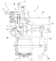
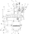
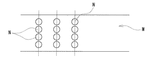
この発明の実施形態であるマルチフィルムに植え付け用の孔を開ける孔開け装置の上面からの斜視図であり、複数の爪が中央に集まっている状態の図1、同じく複数の爪が周辺に移動した状態の図2、同じく孔開け装置の複数の爪が中央に集まっている状態の底面図である図3、同じく複数の爪が周辺に移動した状態の図4、同じく複数の爪が中央に集まっている状態の正面断面図である図5、この発明の実施形態であるマルチフィルムに植え付け用の孔を開ける孔開け装置が設けられたニンニク等の球根植え付け装置の平面図である図6、同じく正面図である図7、この発明のニンニク等の球根植え付け装置の作動状態を説明する右側面図である図8乃至図15、同じく左側面図を示す図16、同じく左側から見た内部作動を示す図17、同じくフレーム前後移動手段の後進速度が、走行装置の前進速度が略同速度となるようにフレーム前後移動手段と走行装置とを同調させる機構の説明図である図18、同じく植付けホルダーの先端部の拡大図である図19、同じく球根保持部に球根を保持した状態を示す拡大図である図20、ニンニク等の球根を植え付ける畝の平面説明図である図21、この発明の孔開け装置の複数の爪が中央から周辺へ往復移動する爪の垂直部の軌跡を示す平面説明図である図22に基づいて説明する。 It is a perspective view from the upper surface of the drilling apparatus which opens the hole for planting in the multi-film which is embodiment of this invention, FIG. 1 of the state which several nail gathered in the center, Similarly several nail | claw moves to the periphery FIG. 2 in a state where the plurality of claws of the punching device are gathered in the center, FIG. 3 which is a bottom view of the state where the plurality of claws are moved to the periphery, and FIG. FIG. 5 is a front sectional view of the assembled state, FIG. 6 is a plan view of a bulb planting device such as garlic provided with a drilling device for drilling a planting hole in the multifilm according to the embodiment of the present invention, FIG. 7 which is also a front view, FIGS. 8 to 15 which are right side views for explaining the operating state of a bulb planting apparatus such as garlic of the present invention, FIG. 16 which is also a left side view, and internal operation which is also viewed from the left side. FIG. FIG. 18 is an explanatory view of a mechanism for synchronizing the frame back-and-forth moving means and the traveling device so that the reverse speed of the frame back-and-forth moving means is substantially the same as the traveling speed of the traveling device. FIG. 19 is an enlarged view of FIG. 19, FIG. 20 is an enlarged view showing a state in which the bulb is held in the bulb holding portion, FIG. 21 is a plan explanatory view of a tub for planting bulbs such as garlic, and the punching device of the present invention. A description will be given based on FIG. 22, which is an explanatory plan view showing the trajectory of the vertical portion of the claw where the plurality of claws reciprocate from the center to the periphery.
次にこの発明の実施形態であるマルチフィルムに植え付け用の孔を開ける孔開け装置について図1乃至図5に基づいて説明する。 Next, a punching device for opening a planting hole in a multi-film according to an embodiment of the present invention will be described with reference to FIGS.
球根植え付け畝Mを被覆しているマルチフィルムに孔を開ける孔開け装置1は、球根植え付け機Aの移動フレーム100に緩衝部材17によって取り付けられている。上下移動フレーム100は、フレーム上下移動手段7及びフレーム前後移動手段8によって主フレーム101に対して上下移動及び前後移動する。孔開け装置1は、上下移動フレーム100に対して上下移動可能なベースプレート15と、ベースプレート15に植え付け条列数に対応して複数設けられる、この実施例では4つの孔開け部10と、上下移動フレーム100に一端を取り付けられ他端を孔開け部10の爪作動リング14に取り付けられる連結リンク18とを有する。上下移動フレーム100は、フレーム上下移動手段7のラック71に固定され前後移動フレーム103の2本の垂直ポール103aに係合して上下移動する。
The
ベースプレート15は、長さがほぼ植え付け畝幅程度の長方形の板状体からなり、各孔開け部10が位置する部分は円状に開口しており、後述する球根植え付け機Aの移動フレーム100に長手方向の両端部にそれぞれ設けられた緩衝部材17、17によって伸縮自在に取り付けられている。この実施例ではそれぞれの緩衝部材17は、いわゆるパンダグラフからなる。すなわち、それぞれの緩衝部材17は、中間回動部17bで回動自在な左右の折畳リンク17aによって上下移動フレーム100に取り付けられている。そして、左右の折畳リンク17aは、下端でベースプレート15の幅方向2カ所で回動自在に取り付けられており、上端で取付部17cを介して上下移動フレーム100に取り付けられており、中間回動部17bの近傍、この実施例では下方に左右の折畳リンク17aを近づける方向へ付勢しているスプリング17dを設けている。
The
各孔開け部10は、ベースプレート15の開口部に設けられており、植え付け予定位置Nの中心NCから周辺NO方向へ水平移動しつつマルチフィルムMFを破る複数の爪11と、各爪11を作動させ長円孔12bを有する複数の爪作動アーム12と、各爪作動アーム12を時間差的に作動させ得るように長円孔12bに係合する爪作動ピン13を有するリング状の爪作動リング14と、ベースプレート15の開口部に取り付けられ下方へ突出している底面円形開口部19とを有している。爪作動アーム12は、ベースプレート15に固定されているアーム回動支点12aを中心に回動可能である。
Each
複数の爪11は、この実施形態では4本の棒状体からなり、各棒状体は水平部11aから垂直方向へ折れ曲がった垂直部11bを有する棒状体からなり、水平部11aの端部は爪作動アーム部12に固定されて連結している。それぞれの爪11の垂直部11bは、底面円形開口部19から下方に20mm程度突出させて設けられており爪作動アーム部12の作動によりそれぞれ植え付け予定位置Nの中心NCから周辺NO方向へやや弧状の移動軌跡NLによって往復移動可能である。
In this embodiment, the plurality of
各爪作動アーム12は、ベースプレート15に固定されている作動アーム回動部12aを中心に回動可能であり、作動アーム回動部12aより外周方向にそれぞれ長円孔12bを有する。長円孔12bの正確な形状はやや湾曲した弧状の長円であり、爪作動リング14に設けられた爪作動ピン13と係合している。
Each
複数の爪作動ピン13を有するリング状の爪作動リング14は、連動ロット16によって連結されており連動してそれぞれ同じ作動を行うとともに、一つの爪作動リング14は、連結リンク18に連結している。
A ring-like
連結リンク18は、ベースプレート15の長手方向中央部近傍に設けられ垂直杆18aの上端をフレーム100に固定し下端でくの字状に曲がった曲杆18bの一端と回動自在に連結し、曲杆18bは他端で水平方向に移動可能な水平杆18cの一端と回動自在に連結しており、水平杆18cの他端は爪作動リング14の一つに連結している。
The connecting
次にこの発明の実施形態であるマルチフィルムに植え付け用の孔を開ける孔開け装置1の作動について説明する。
Next, the operation of the
ニンニク等の球根植え付け機Aの球根Gの載置プレート3が設けられている主フレーム101に対して、フレーム上下移動手段7によって下降する上下移動フレーム100に従って孔開け装置1も下降に従って下降する。この下降距離は後述するニンニク等の球根植え付け機Aの植付けホルダー上下移動制御手段(図示せず)によって決定され指示される。このとき孔開け部10のそれぞれの爪11は垂直部11bを植え付け中心に位置しており互いに接して集合された太い棒状になっている。上下移動フレーム100が下降していくとベースプレート15の底面円形開口部19がマルチフィルムMFの上面に当接するが更に一定距離下降する。
With respect to the
上下移動フレーム100が下降してベースプレート15がマルチフィルム上面へ接した後、更に上下移動フレーム100が下降して押圧されるとパンダグラフである緩衝部材17は間隔を短縮させ、連結リンク18の垂直杆18aは下降する。このとき孔開け部10の中心に集まっている4本の爪11の垂直部11bがマルチフィルムMFを上面から突き刺して破る。
After the vertically moving
緩衝部材17は、左右の折畳リンク17aの中間回動部17bがスプリング17dの付勢力に抗して互いに外方へ折り畳まれ上下移動フレーム100とベースプレート15の間隔を縮める。
In the
連結リンク18の垂直杆18aが下降することにより、曲杆18bが回動し水平杆18cが一定の水平方向へ一定距離移動する。水平杆18cの一端は爪作動リング14が一定方向へ回動し、連動ロッド16によってすべての爪作動リング14が同じように同じ方向へ回動する。
As the
爪回動リング14が回動すると、4つの爪作動ピン13も回動するが、爪作動ピン13が係合する長円孔12bにより爪作動アーム12は、爪作動ピン13が長円孔12bの円内の端部から端部までの距離作動しない。この間に確実に爪11の垂直部11bが植え付け予定位置中心NCのマルチフィルムMFを上面から突き刺し差し込まれる。この時間差の後に爪作動ピン13が長円孔12bの一端部を押すため爪作動アーム12は、アーム回動部12aを中心に回動してそれぞれの爪11の垂直部11bを図22に示すように、やや弧状の軌跡NLを描いてそれぞれ植え付け予定位置の外周NO方向へ移動することによりマルチフィルムMFを破り、植え付け用の孔をマルチフィルムMFに形成する。
When the
植え付け用孔Nが形成された後、植付けホルダー上下移動制御手段(図示せず)の指示によって上下移動フレーム100が上昇し始め移動フレーム100からの押圧力が解除されると、緩衝部材17は、スプリング17dの付勢力によって左右2つの折畳みリンク17aの間隔を狭めて上下移動フレーム100とベースプレート15の間隔を広げる。
After the planting hole N is formed, when the
上下移動フレーム100とベースプレート15の間隔が広がると、連結リンク18の垂直杆18aが上昇し、曲杆18bが回動し水平杆18cが逆方向の水平方向へ一定距離移動するため、連結している爪作動リング14も一定の逆方向へ回動し、連動ロッド16によってすべての爪作動リング14が同じように逆方向へ回動する。この爪作動リング14の逆方向への回動によってそれぞれの爪11も弧状の軌跡によって中心に集まって接する状態になる。この作動を繰り返す。
As the distance between the vertically moving
次にこの発明の一つの実施形態であるニンニク等の球根植え付け機Aについて図6、図7、図8、図16及び図17に基づいて説明する。 Next, a bulb planting machine A such as garlic, which is one embodiment of the present invention, will be described with reference to FIGS. 6, 7, 8, 16 and 17.
この発明のニンニク等の球根植え付け機Aは、この実施形態ではクローラ走行部20で走行する走行装置2に着脱可能に載置されているが、他の実施形態では人力走行する装置に載置しても作業は可能である。この走行装置2の左右のクローラ走行部20の幅間隔は、球根植え付け畝Mを跨いで走行可能な幅に設けられている。21は走行装置の運転操作部であり、運転操作部21は、走行装置2の後部左右に設けられている2つの作業者用シート22に挟まれて設けられる。23はエンジン、24は変速機であり、エンジン出力プーリ25と変速機入力プーリ26をベルトによって伝動する。
In this embodiment, the bulb planting machine A such as garlic of the present invention is detachably mounted on the traveling
この発明のニンニク等の球根植え付け機Aは、主フレーム101に取り付けられニンニク等の球根を載置する球根載置プレート3と、反転フレーム102に取り付けられたニンニク等の球根の植付けホルダー4と、主フレーム101に取り付けられ球根載置プレート3に載置されたニンニク等の球根を植付けホルダー4に装填する球根装填手段5と、水平軸を回動中心として反転フレーム102を上下反転させるフレーム上下反転手段6と、上下移動フレーム100を垂直方向に移動させるフレーム上下移動手段と、前後移動フレーム103を進行する前後方向に移動させるフレーム前後移動手段8と、反転フレーム102に取り付けられ植付けホルダー4に装填された球根をホルダーから押し出して土中へ押し入れて植え付ける球根植え付け手段9と、上下移動フレーム100に取り付けられ球根植え付け畝Mを被覆しているマルチフィルムに球根植え付け用の孔を開ける孔開け装置10とを有する。
A garlic bulb planter A according to the present invention includes a
球根載置プレート3は、複数の上下貫通孔からなる載置部31を有する水平方向に間欠的に回転可能な複数の円形板状体30と、円形板状体30を円形板状体回転軸33を中心に間欠的に回転させる回転駆動部32とからなり、主フレーム101に取り付けられている。球根植え付け機Aが走行装置2に備え付けられた場合は、作業者用シート22の前に設けられる。この実施形態では円形板状体30は4つ横方向に並設されており、それぞれの円形板状体30は、その外周部分に90度角間隔で載置部31を設けている。それぞれの載置部31は、球根Gを上下方向にした状態で保持可能であるとともに、作業者が載置部31へ球根を載せる位置と、円形板状体30の上方に位置する球根装填手段5によって載置部31の球根Gを植付けホルダー4へ装填する位置とを水平方向へ間欠的に回転する。この実施形態では作業者が載置部31へ球根を載せる位置と植付けホルダー4へ装填する位置とは180度角の間隔に設けられており90度角ごとの回転によって間欠的に停止する。間欠移動角度及び載置部31の数は、作業速度に合わせて任意に設定することができる。
The
植付けホルダー4は、球根Gを保持可能な凹状の球根保持部40と、球根保持部40の中心から放射状に外周に配置され中心方向へ付勢されている外周保持部41とを有し、反転フレーム102に取り付けられている。植付けホルダー4は、球根載置プレート3の載置部31の下方の位置で球根保持部40の凹状開口を上方に向けた状態で位置しており、フレーム上下反転手段6によって球根保持部40の凹状開口を下方に向けた状態に上下180度回動し、球根保持部40の凹状開口を下方に向けた状態のときにフレーム上下移動手段7によって垂直方向に上下動する。
The
外周保持部41は、この実施形態では中心方向へ付勢される複数本の棒状スプリング材からなり、球根保持部40の外周に固定されて設けられる。球根保持部40は、球根Gの先端側を凹状の内方向へ向けて載置され得る凹状部を有し、外周保持部41の外周内側で外周保持部41の先端側から基部方向の中側に位置している(図19参照)。球根保持部40が図19の位置のときに球根保持部40の球根Gは、その外側を外側から外周保持部41によって保持されている。球根保持部40は、押出しシャフト90によって外周保持部41の先端方向へ移動し、更に押出しシャフト90は外周保持部41によって保持されていた球根Gを、外周保持部41の先端から外に押し出し、土中へ押し入れて一定の深さに植え付ける。(図20参照)。
In this embodiment, the outer
球根植え付け手段9は、押出しシャフト90とモータであるシャフト駆動部91からなり、反転フレーム102に取り付けられている。シャフト駆動部91の駆動により押出シャフト90は、植付けホルダー4の外周保持部41の中心位置を基部から先端部方向へ往復移動可能である。押出しシャフト90は、植付けホルダー4の球根保持部40に装填された球根Gを球根保持部40、外周保持部41から押し出して植え付け位置の土中へ押し入れて一定の深さに植え付ける。
The bulb planting means 9 includes an
球根装填手段5は、球根載置プレート3の上方に位置し、主フレーム101に固定された支持部51と、昇降駆動部52が昇降する垂直方向に設けられた昇降棒53と、昇降駆動部52に連結部54によって連結固定されているプッシュロッド50とを有している。昇降棒53も上下移動フレーム100に垂直方向に固定されて、昇降駆動部52は、昇降棒53を昇降可能に設けられている。球根装填手段5のプッシュロッド50は、球根載置プレート3の載置部31の上方に位置し、昇降駆動部52の昇降に従って上下し、載置部31に置かれているニンニク等の球根Gを上から押し出して、載置部31の下方に位置する植付けホルダー4の球根保持部40に装填する。
The bulb loading means 5 is located above the
フレーム上下反転手段6は、水平軸60を回動中心として上下反転駆動部61によって反転フレーム102を回転させ、反転フレーム102に取り付けられた植付けホルダー4及び球根植え付け手段9を上下反転させる。
The frame up / down inversion means 6 rotates the
フレーム上下移動手段は、前後移動フレーム103に設けられるピニオン70と、ピニオン70と噛合し垂直方向に上下移動するラック71からなる。ピニオン70は、モータからなる駆動部72によって回転し、ラック71には上下移動フレーム100が取り付けられており、ラック71の上下移動に伴い上下移動フレーム100に取り付けられている反転フレーム103も上下移動する。同時に反転フレーム103に取り付けられている植付けホルダー4、植え付け手段9も上下移動する。
The frame vertical movement means includes a
フレーム前後移動手段8は、前後移動フレーム103を前後に移動する手段であり、図18に示すように走行装置2のクローラ走行部20の車軸27を駆動させる変速機24と連結しているユニバーサルジョイント80、電磁クラッチ81、第1スプロケット82、ローラーチェーン83、第2スプロケット84、クランクアーム85、及び連結ロット86からなる。変速機24は、エンジン23に連結しておりクローラ走行部20の車軸27を回転させるとともに、その同じ回転数をユニバーサルジョイント80、電磁クラッチ81、第1スプロケット82、ローラーチェーン83、第2スプロケット84を介してクランクアーム85に伝動し、クランクアーム85を回転させる。クランクアーム85の回転に伴い植付けホルダー4、押し付けシャフト90等を備えているフレーム100は、クランクアーム85と連結ロット86で連結されて前後に移動可能である。このフレーム前後移動手段8により植付けホルダー4、押し付けシャフト90等の後進速度が、走行装置2の前進速度と略同速度となるように走行装置2を同調させている。電磁クラッチ81は、各作動機構とのタイムラグを調整するためにON・OFF作動する。
The frame front / rear moving means 8 is means for moving the front /
この発明のニンニク等の球根植え付け機Aの主フレーム101には、球根載置プレート3及び球根装填手段5及び前後移動フレーム103が取り付けられている。前後移動フレーム103は、主フレーム101の水平方向に設けられたレールに取り付けられている。前後移動フレーム103には、フレーム上下移動手段7のピニオン70及び上下移動可能に上下移動フレーム100が取り付けられている。上下移動フレーム100は、フレーム上下移動手段7のラック71に固定され前後移動フレーム103の2本の垂直ポール103aに係合して上下移動する。上下移動フレーム100の下部に孔開け装置1が取り付けられているとともに反転フレーム102が水平軸60を中心に反転回動可能に取り付けられている。
A
走行装置2は、マルチフィルム上面位置検出手段200と、植付けホルダー上下移動制御手段(図示せず)とを設けている。マルチフィルム上面位置検出手段200は、植付けホルダー4の支持フレーム204に一端が回動部203によって上下回動自在に設けられるとともに、他端にマルチフィルムMFの上面をトレースするマルチフィルム上面当接部202を有するセンサーアーム201を有する。マルチフィルム上面当接部202はローラからなる。
The traveling
植付けホルダー上下移動制御手段(図示せず)は、センサーアーム201と支持フレーム204との回動部203の回動角の変化により検出した角度信号を、ホルダーを上下移動手段7に伝達して、植付けホルダー4の上下移動の位置制御をマルチフィルムMFの上面を基準に制御する。
The planting holder vertical movement control means (not shown) transmits an angle signal detected by the change in the rotation angle of the
上述した各駆動部は、この実施例ではモータであるが、シリンダー装置を使用してもよい。 Each drive unit described above is a motor in this embodiment, but a cylinder device may be used.
次にこの発明の実施形態である走行装置2に備え付けられたニンニク等の球根植え付け機Aの作動について図6及び図8乃至図15に基づいて説明する。
Next, the operation of the bulb planting machine A such as garlic provided in the traveling
作業者は、走行装置2の作業者用シート22に通常2人が座り、どちらかの人が走行装置2の運転操作部21を操作して操縦する。運転操作部21の操作によってエンジン23が掛かり変速機24、車軸27を介してクローラ走行部20を回転させ、走行装置2を走行させる。走行装置2は、畝Mを跨ぐように畝間にクローラ走行部20を走らせる。
Two workers normally sit on the worker's
ニンニク等の球根植え付け機Aは、図8において球根載置プレート3の載置部31には球根Gが載置されており、球根装填手段5のプッシュロッド50は、載置部31の上方に位置し、植付けホルダー4の球根保持部40は、載置部31の下方に位置している。作業者が2人の場合は、それぞれ作業用シート22の前の球根載置プレート3を二つずつ受け持って球根Gを、載置部31に先端側Aを下にして挿入する。このとき球根載置プレート3の回転は停止されている。
In the bulb planting machine A such as garlic, the bulb G is placed on the
次に、球根装填手段5の昇降駆動部52が作動し、昇降駆動部52が昇降棒53を下降する。昇降駆動部52が降下し始めると連結しているプッシュロッド50も下降し(図9)、プッシュロッド50が載置部31に載置されていた球根Gを下方に位置する植付けホルダー4の球根保持部40まで押し出し装填する(図10)。
Next, the raising / lowering
プッシュロッド50は、植付けホルダー4の球根保持部40に球根Gを装填する位置まで下降後、直ぐに昇降駆動部52が昇降棒53を上昇し始めプッシュロッド50を元の位置に停止させる(図11)。
After the
プッシュロッド50が載置部31から上方に位置すると、球根載置プレート3の円形板状体30が、90度角回転し、球根Gを載置した次の載置部31をプッシュロッド50の下方位置に位置させる。この球根載置プレート3の円形板状体30の回転とともに、フレーム上下反転手段6と、フレーム前後移動手段8が作動し始め、植付けホルダー4が取り付けられている上下移動フレーム100が、前進方向へ移動し始めるとともに水平軸60を中心に上下反転し始める。そして植付けホルダー4が取り付けられている上下移動フレーム100は最前位置に移動し、植付けホルダー4は180度上下反転して球根保持部40は下方を向いた状態になるため、球根Gの先端部Aは上方を向く(図12)。
When the
このとき、フレーム前後移動手段8は、クローラ走行部20の車軸27を駆動させる変速機24と連結しており、車軸27の回転速度と同調した動きをクランクアーム85に伝え、クランクアーム85の回転により連結ロット86を前進及び後退させることにより前後移動フレーム103を進行方向に対して前後移動させる。電磁クラッチ81は、クランクアーム85の動きを停止したい場合にクラッチを切る。
At this time, the frame back-and-forth moving means 8 is connected to the
次に図8に示すようにマルチフィルム上面位置検出手段200のローラーからなるマルチフィルム上面当接部202がマルチフイルムMFの上面をトレースすることで、マルチフィルムMF上面とクローラ走行部20が走行する畝間面との高さ相違が生じた場合でも、マルチフィルムMFの上面を基準として支持フレーム204とセンサーアーム201の回動部203の角度が変化し、その角度変化に対応して、植付けホルダー上下移動制御手段(図示せず)が作動し、ホルダー上下移動装置7を作動させるとともにその下降距離を調整する。ホルダー上下移動装置7の下降により植付けホルダー4の球根保持部40の位置が、マルチフィルムMF上面に近接した高さまで降下して停止する。
Next, as shown in FIG. 8, the multi-film upper
フレーム上下移動手段7による上下移動フレーム100の下降により孔開け装置1の下面がマルチフィルムMFを押圧する。この押圧によって孔開け装置1の爪11の垂直部11bがマルチフィルムMFを上面から破り、更なるこの押圧力により孔開け装置1の連結リンク17が作動して爪作動リング14が回動し、爪作動ピン13を介して爪作動アーム12が作動し球根植え付け畝Mを被覆しているマルチフィルムMFに球根植え付け用の孔を開ける。孔開け装置1の各孔開け部10は、4本の棒状の爪11を植え付け予定位置の中心のマルチフィルムMFを上面から突き刺した後、中心NCから周辺NO方向へ移動しつつマルチフィルムMFを破る。
When the
次に球根植え付け手段9のシャフト駆動部91が作動し、押出しシャフト90を植付けホルダー4の外周保持部41の中心位置を基部から先端部方向へ下降させる。押出しシャフト90は、植付けホルダー4の球根保持部40に装填された球根Gを球根保持部40、外周保持部41から押し出して植え付け位置の土中へ押し入れて一定の深さに植え付ける(図14参照)。
Next, the
球根植え付け手段9の押出しシャフト90の下降及び上昇作動をしている時間は、フレーム前後移動手段8が作動して走行装置2の前進速度と略同速度で植付けホルダー4、押し付けシャフト90を後進させているため、押出シャフト90、植付けホルダー4は、球根植え付け位置で前後移動を停止し上下移動することができる。
During the time when the push-out
図15に示すように押出しシャフト90は、一定の深さまで下降して土中に球根Gを植え付けた後、上昇し土中から出ると、再びフレーム上下反転手段6が作動して反転フレーム102が180度上下反転する。反転フレーム102に取り付けられている植付けホルダー4は180度上下反転して球根保持部40は上方を向いた状態になる。同時にフレーム上下移動手段7が作動して上下移動フレーム100を上昇させ、反転フレーム102及び植付けホルダー4を上昇させるとともにフレーム前後移動手段8による前後移動フレーム103の後進を停止する。この状態で図8の位置に各部材、装置は戻る。
As shown in FIG. 15, the push-out
この作動を一つの植え付けサイクルとして、走行装置2の走行とともに順次ニンニクを植え付けていく。
With this operation as one planting cycle, garlic is planted sequentially as the traveling
この発明は、ニンニク等の球根類の植え付け作業、特に専業的なニンニク等の球根の収穫を目的とする広い作付け面積の圃場に利用可能性が高い。 The present invention is highly applicable to a field of a large planting area for the purpose of planting bulbs such as garlic, particularly for harvesting bulbs such as professional garlic.
1 孔開け装置
10 孔開け部
11 爪
11a 水平部
11b 垂直部
12 爪作動アーム
12a アーム回動支点
12b 長円孔
13 爪作動ピン
14 爪作動リング
15 ベースプレート
16 連動ロット
17 緩衝部材(パンダグラフ)
17a 折畳みリンク
17b 中間回動部
17c 取付部
17d スプリング
18 連結リンク
19 底面開口部
100 上下移動フレーム
101 主フレーム
102 反転フレーム
103 前後移動フレーム
103a 垂直ポール
2 走行装置
20 クローラ走行部
21 運転操作部
22 作業者シート
23 エンジン
24 変速機
25 エンジン出力プーリ
26 変速機入力プーリ
27 車軸
200 マルチフィルム上面位置検出手段
201 センサーアーム
202 マルチフィルム上面当接部
203 回動部
204 支持フレーム
3 球根載置プレート
30 円形板状体
31 載置部
4 植付けホルダー
40 球根保持部
41 外周保持部
5 球根装填手段
50 プッシュロッド
51 支持部
52 昇降駆動部
53 昇降棒
54 連結部
6 フレーム上下反転手段
60 水平軸
61 上下反転駆動部
7 ホルダー上下移動手段
70 ピニオン
71 ラック
72 駆動部
8 フレーム前後移動手段
80 ユニバーサルジョイント
81 電磁クラッチ
82 第1スプロケット
83 ローラーチェーン
84 第2スプロケット
85 クランクアーム
86 連結ロット
9 球根植え付け手段
90 押出しシャフト
91 シャフト駆動部
A 球根植え付け機
G ニンニク等の球根
M ニンニク等の球根を植える畝
MF マルチフィルム
N 球根の植え付け予定位置
NC 球根の植え付け予定位置の中心
NO 球根の植え付け予定位置の周辺
NL 爪の垂直部の移動軌跡
DESCRIPTION OF
12a Arm pivot point
6 Frame vertical reversing
8 Frame back-and-forth moving means 80 Universal joint 81 Electromagnetic clutch 82
Claims (6)
孔開け装置は、開口部を有するベースプレートと、前記開口部から下方に突出し植え付け予定位置の中心から周辺方向へ水平移動しつつマルチフィルム上面を破る複数の爪と、前記爪を保持して水平方向に移動させる爪作動部と、複数の前記爪を連動させるリンク部と、を有するとともに、複数の爪が集合する中心位置が、植え付けホルダー及び球根植え付け手段の上下移動軸と一致しており、複数の爪が、植え付け予定位置の中心から周辺方向へ水平移動しつつマルチフィルム上面を破って植え付け用孔を開けた直後に球根植え付け手段により球根を植え付けることが可能なことを特徴とする孔開け装置を有する球根植え付け機。 A traveling device, a bulb planting holder, a frame holder up-and-down moving means for moving the frame to which the planting holder is attached in the vertical direction, and a frame back-and-forth moving means for moving the frame to which the planting holder is attached in the front-rear direction. The bulb planting means for pushing out the bulb loaded in the planting holder from the holder and pushing it into the soil and planting, and a punching device for drilling a bulb planting hole in the multi-film covering the bulb planting basket,
The punching device includes a base plate having an opening, a plurality of claws that project downward from the opening and horizontally move from the center of the planned planting position to the peripheral direction and break the upper surface of the multi-film, and hold the claws in a horizontal direction. A center portion where the plurality of claws are gathered coincides with the vertical movement axis of the planting holder and the bulb planting means. Drilling device characterized in that the nail can plant the bulb by the bulb planting means immediately after opening the planting hole by breaking the upper surface of the multi-film while moving horizontally from the center of the planting planned position to the peripheral direction A bulb planting machine.
孔開け装置は、開口部を有するベースプレートと、前記開口部から下方に突出し植え付け予定位置の中心から周辺方向へ水平移動しつつマルチフィルム上面を破る複数の爪と、前記爪を保持して水平方向に回動移動させる爪作動部と、複数の前記爪を連動させるリンク部と、を有するとともに、複数の爪が集合する中心位置が、植え付けホルダー及び球根植え付け手段の上下移動軸と一致しており、複数の爪が、植え付け予定位置の中心から周辺方向へ水平移動しつつマルチフィルム上面を破って植え付け用孔を開けた直後に球根植え付け手段により球根を植え付けることが可能なことを特徴とする孔開け装置を有する球根植え付け機。 A traveling device, a bulb planting holder, a frame holder up-and-down moving means for moving the frame to which the planting holder is attached in the vertical direction, and a frame back-and-forth moving means for moving the frame to which the planting holder is attached in the front-rear direction. The bulb planting means for pushing out the bulb loaded in the planting holder from the holder and pushing it into the soil and planting, and a punching device for drilling a bulb planting hole in the multi-film covering the bulb planting basket,
The punching device includes a base plate having an opening, a plurality of claws that project downward from the opening and horizontally move from the center of the planned planting position to the peripheral direction and break the upper surface of the multi-film, and hold the claws in a horizontal direction. A claw actuating portion that pivots and a link portion that links the plurality of claws, and the center position where the plurality of claws gather coincides with the vertical movement axis of the planting holder and the bulb planting means. A hole characterized in that a plurality of claws can plant a bulb by a bulb planting means immediately after opening a planting hole by breaking the upper surface of the multi-film while moving horizontally from the center of the planned planting position to the peripheral direction. Bulb planting machine with opening device.
Priority Applications (1)
| Application Number | Priority Date | Filing Date | Title |
|---|---|---|---|
| JP2009171179A JP4432093B2 (en) | 2009-07-22 | 2009-07-22 | Drilling device for drilling holes for planting in multi-film and bulb planter having the drilling device |
Applications Claiming Priority (1)
| Application Number | Priority Date | Filing Date | Title |
|---|---|---|---|
| JP2009171179A JP4432093B2 (en) | 2009-07-22 | 2009-07-22 | Drilling device for drilling holes for planting in multi-film and bulb planter having the drilling device |
Related Parent Applications (1)
| Application Number | Title | Priority Date | Filing Date |
|---|---|---|---|
| JP2008101691A Division JP4431653B2 (en) | 2008-04-09 | 2008-04-09 | Drilling device for drilling holes for planting in multi-film and bulb planter having the drilling device |
Publications (2)
| Publication Number | Publication Date |
|---|---|
| JP2009247357A JP2009247357A (en) | 2009-10-29 |
| JP4432093B2 true JP4432093B2 (en) | 2010-03-17 |
Family
ID=41308628
Family Applications (1)
| Application Number | Title | Priority Date | Filing Date |
|---|---|---|---|
| JP2009171179A Active JP4432093B2 (en) | 2009-07-22 | 2009-07-22 | Drilling device for drilling holes for planting in multi-film and bulb planter having the drilling device |
Country Status (1)
| Country | Link |
|---|---|
| JP (1) | JP4432093B2 (en) |
-
2009
- 2009-07-22 JP JP2009171179A patent/JP4432093B2/en active Active
Also Published As
| Publication number | Publication date |
|---|---|
| JP2009247357A (en) | 2009-10-29 |
Similar Documents
| Publication | Publication Date | Title |
|---|---|---|
| JP3142590U (en) | Bulb planting equipment such as garlic | |
| JP4431653B2 (en) | Drilling device for drilling holes for planting in multi-film and bulb planter having the drilling device | |
| JP4432093B2 (en) | Drilling device for drilling holes for planting in multi-film and bulb planter having the drilling device | |
| JP5303775B2 (en) | Bulb planting machine for garlic etc. | |
| JP2012034657A (en) | Method for planting or sowing seedling in film mulching culture, agricultural machine, and agricultural machine attachment | |
| JP6187002B2 (en) | Transplanter | |
| JPH10178830A (en) | Transplanter | |
| JP2005021061A (en) | Sulky type seedling transplanter | |
| JP2010022272A (en) | Bulb-planting apparatus for garlic or the like | |
| JP2008154533A (en) | Apparatus for taking out seedling for transplanter | |
| JP2010098989A (en) | Planting machine for bulb such as garlic | |
| JP3898200B2 (en) | Transplanter seedling extraction device | |
| JP2017209046A (en) | Bulb loading section of bulb planting machine | |
| JP2006158358A (en) | Seedling transplanter | |
| JP4753857B2 (en) | Transplanter seedling removal device | |
| JP4193941B2 (en) | Seedling transplanter | |
| JP3356385B2 (en) | Implanting device of transplanter | |
| JP2010000053A (en) | Apparatus for planting bulbs of garlic or the like | |
| JP3634771B2 (en) | Transplanting device for transplanting machine | |
| JP2010022274A (en) | Bulb-planting apparatus for garlic or the like | |
| JP2010000057A (en) | Apparatus for planting bulbs of garlic or the like | |
| JP3968530B2 (en) | Streak adjustment method in seedling transplanter | |
| JP2013055918A (en) | Seedling transplanter | |
| JP2013046582A (en) | Planting system for transplanter | |
| JP2006141262A (en) | Pressurizing device of transplanter |
Legal Events
| Date | Code | Title | Description |
|---|---|---|---|
| A621 | Written request for application examination |
Free format text: JAPANESE INTERMEDIATE CODE: A621 Effective date: 20090810 |
|
| A871 | Explanation of circumstances concerning accelerated examination |
Free format text: JAPANESE INTERMEDIATE CODE: A871 Effective date: 20090810 |
|
| A975 | Report on accelerated examination |
Free format text: JAPANESE INTERMEDIATE CODE: A971005 Effective date: 20091027 |
|
| TRDD | Decision of grant or rejection written | ||
| A01 | Written decision to grant a patent or to grant a registration (utility model) |
Free format text: JAPANESE INTERMEDIATE CODE: A01 Effective date: 20091201 |
|
| A01 | Written decision to grant a patent or to grant a registration (utility model) |
Free format text: JAPANESE INTERMEDIATE CODE: A01 |
|
| A61 | First payment of annual fees (during grant procedure) |
Free format text: JAPANESE INTERMEDIATE CODE: A61 Effective date: 20091211 |
|
| R150 | Certificate of patent or registration of utility model |
Ref document number: 4432093 Country of ref document: JP Free format text: JAPANESE INTERMEDIATE CODE: R150 Free format text: JAPANESE INTERMEDIATE CODE: R150 |
|
| FPAY | Renewal fee payment (event date is renewal date of database) |
Free format text: PAYMENT UNTIL: 20130108 Year of fee payment: 3 |
|
| FPAY | Renewal fee payment (event date is renewal date of database) |
Free format text: PAYMENT UNTIL: 20130108 Year of fee payment: 3 |
|
| FPAY | Renewal fee payment (event date is renewal date of database) |
Free format text: PAYMENT UNTIL: 20160108 Year of fee payment: 6 |
|
| R250 | Receipt of annual fees |
Free format text: JAPANESE INTERMEDIATE CODE: R250 |
|
| R250 | Receipt of annual fees |
Free format text: JAPANESE INTERMEDIATE CODE: R250 |
|
| R250 | Receipt of annual fees |
Free format text: JAPANESE INTERMEDIATE CODE: R250 |
|
| R250 | Receipt of annual fees |
Free format text: JAPANESE INTERMEDIATE CODE: R250 |
|
| R250 | Receipt of annual fees |
Free format text: JAPANESE INTERMEDIATE CODE: R250 |
|
| R250 | Receipt of annual fees |
Free format text: JAPANESE INTERMEDIATE CODE: R250 |
|
| R250 | Receipt of annual fees |
Free format text: JAPANESE INTERMEDIATE CODE: R250 |
|
| R250 | Receipt of annual fees |
Free format text: JAPANESE INTERMEDIATE CODE: R250 |
|
| R250 | Receipt of annual fees |
Free format text: JAPANESE INTERMEDIATE CODE: R250 |
|
| R250 | Receipt of annual fees |
Free format text: JAPANESE INTERMEDIATE CODE: R250 |