JP4430552B2 - Intake device for V-type engine - Google Patents
Intake device for V-type engine Download PDFInfo
- Publication number
- JP4430552B2 JP4430552B2 JP2005010501A JP2005010501A JP4430552B2 JP 4430552 B2 JP4430552 B2 JP 4430552B2 JP 2005010501 A JP2005010501 A JP 2005010501A JP 2005010501 A JP2005010501 A JP 2005010501A JP 4430552 B2 JP4430552 B2 JP 4430552B2
- Authority
- JP
- Japan
- Prior art keywords
- fuel
- boss
- connection pipe
- throttle
- injection valve
- Prior art date
- Legal status (The legal status is an assumption and is not a legal conclusion. Google has not performed a legal analysis and makes no representation as to the accuracy of the status listed.)
- Expired - Fee Related
Links
Images


Classifications
-
- F—MECHANICAL ENGINEERING; LIGHTING; HEATING; WEAPONS; BLASTING
- F02—COMBUSTION ENGINES; HOT-GAS OR COMBUSTION-PRODUCT ENGINE PLANTS
- F02M—SUPPLYING COMBUSTION ENGINES IN GENERAL WITH COMBUSTIBLE MIXTURES OR CONSTITUENTS THEREOF
- F02M69/00—Low-pressure fuel-injection apparatus ; Apparatus with both continuous and intermittent injection; Apparatus injecting different types of fuel
- F02M69/46—Details, component parts or accessories not provided for in, or of interest apart from, the apparatus covered by groups F02M69/02 - F02M69/44
- F02M69/462—Arrangement of fuel conduits, e.g. with valves for maintaining pressure in the pipes after the engine being shut-down
-
- F—MECHANICAL ENGINEERING; LIGHTING; HEATING; WEAPONS; BLASTING
- F02—COMBUSTION ENGINES; HOT-GAS OR COMBUSTION-PRODUCT ENGINE PLANTS
- F02D—CONTROLLING COMBUSTION ENGINES
- F02D9/00—Controlling engines by throttling air or fuel-and-air induction conduits or exhaust conduits
- F02D9/08—Throttle valves specially adapted therefor; Arrangements of such valves in conduits
- F02D9/10—Throttle valves specially adapted therefor; Arrangements of such valves in conduits having pivotally-mounted flaps
- F02D9/1035—Details of the valve housing
-
- F—MECHANICAL ENGINEERING; LIGHTING; HEATING; WEAPONS; BLASTING
- F02—COMBUSTION ENGINES; HOT-GAS OR COMBUSTION-PRODUCT ENGINE PLANTS
- F02D—CONTROLLING COMBUSTION ENGINES
- F02D9/00—Controlling engines by throttling air or fuel-and-air induction conduits or exhaust conduits
- F02D9/08—Throttle valves specially adapted therefor; Arrangements of such valves in conduits
- F02D9/10—Throttle valves specially adapted therefor; Arrangements of such valves in conduits having pivotally-mounted flaps
- F02D9/109—Throttle valves specially adapted therefor; Arrangements of such valves in conduits having pivotally-mounted flaps having two or more flaps
-
- F—MECHANICAL ENGINEERING; LIGHTING; HEATING; WEAPONS; BLASTING
- F02—COMBUSTION ENGINES; HOT-GAS OR COMBUSTION-PRODUCT ENGINE PLANTS
- F02M—SUPPLYING COMBUSTION ENGINES IN GENERAL WITH COMBUSTIBLE MIXTURES OR CONSTITUENTS THEREOF
- F02M69/00—Low-pressure fuel-injection apparatus ; Apparatus with both continuous and intermittent injection; Apparatus injecting different types of fuel
- F02M69/04—Injectors peculiar thereto
- F02M69/042—Positioning of injectors with respect to engine, e.g. in the air intake conduit
- F02M69/044—Positioning of injectors with respect to engine, e.g. in the air intake conduit for injecting into the intake conduit downstream of an air throttle valve
Landscapes
- Engineering & Computer Science (AREA)
- Chemical & Material Sciences (AREA)
- Combustion & Propulsion (AREA)
- Mechanical Engineering (AREA)
- General Engineering & Computer Science (AREA)
- Fuel-Injection Apparatus (AREA)
- Control Of Throttle Valves Provided In The Intake System Or In The Exhaust System (AREA)
Description
本発明は複数の気筒がVバンクをなして配置されるとともにVバンク内に各気筒に連なるスロットルボデーが配置されたV型機関用の吸気装置に関する。 The present invention relates to an intake system for a V-type engine in which a plurality of cylinders are arranged in a V bank and a throttle body connected to each cylinder is arranged in the V bank.
V型機関用の吸気装置は特開平5−248317号公報に示される。
同公報に記載される符号に基づき説明すると,V型機関を構成する上側気筒と下側気筒とのVバンク内に上側吸気通路31aと下側吸気通路31bとを備えるスロットルボデー29が配置され,上側吸気通路31aの上方側壁に上側燃料噴射弁33aが配置され,下側吸気通路31bの下方側壁に下側燃料噴射弁33bが配置される。
そして燃料タンク内の燃料が燃料ポンプ47によって昇圧され,この昇圧された燃料が上側燃料供給ホース48を介して上側燃料噴射弁33aに供給され,一方下側燃料噴射弁33bには下側燃料供給ホース51を介して昇圧された燃料が供給される。
Explaining based on the reference described in the publication, a throttle body 29 having an upper intake passage 31a and a lower intake passage 31b is arranged in a V bank of an upper cylinder and a lower cylinder constituting a V-type engine, An upper fuel injection valve 33a is disposed on the upper side wall of the upper intake passage 31a, and a lower fuel injection valve 33b is disposed on the lower side wall of the lower intake passage 31b.
The fuel in the fuel tank is boosted by the fuel pump 47, and the boosted fuel is supplied to the upper fuel injection valve 33a via the upper
かかる従来のV型機関用の吸気装置によると,上側燃料噴射弁に燃料を供給する上側燃料供給ホースは,スロットルボデーの左側方を通過したのちに上側吸気通路を上側気筒との間に折れ曲がって進入し,次いで上側燃料噴射弁に接続される。
又,下側燃料噴射弁に燃料を供給する下側燃料供給ホースは,スロットルボデーの左側方を通過したのちに下側吸気通路と下側気筒との間に折れ曲がって進入し,次いで下側燃料噴射弁に接続される。
以上の如く,上側及び下側燃料供給ホースが各吸気通路の外側を迂回して配置されることによると,上側及び下側燃料供給ホースのホース長が長くなるもので,燃料供給ホースの配管設計の自由度が制限される。
又,機関の運転時において,長い燃料供給ホースの振れを抑止する為の係止部材を必要とする。
更に上側燃料供給ホースが上側気筒に近接配置され,下側燃料供給ホースが下側気筒に近接配置されるので,燃料供給ホース内を流れる燃料が気筒によって暖められ易く,特に夏場の連続運転時におけるベーパーの発生が懸念される。
According to such a conventional intake device for a V-type engine, the upper fuel supply hose for supplying fuel to the upper fuel injection valve is bent between the upper cylinder and the upper intake passage after passing the left side of the throttle body. Enter and then connect to the upper fuel injector.
The lower fuel supply hose for supplying fuel to the lower fuel injection valve is bent between the lower intake passage and the lower cylinder after passing through the left side of the throttle body, and then enters the lower fuel injection valve. Connected to the injection valve.
As described above, when the upper and lower fuel supply hoses are arranged around the outside of each intake passage, the length of the upper and lower fuel supply hoses becomes longer. The degree of freedom is limited.
In addition, a locking member is required to prevent the long fuel supply hose from swinging during engine operation.
Furthermore, since the upper fuel supply hose is disposed close to the upper cylinder and the lower fuel supply hose is disposed close to the lower cylinder, the fuel flowing in the fuel supply hose is easily warmed by the cylinder, especially during continuous operation in summer. There is concern about the generation of vapor.
本発明になるV型機関用の吸気装置は,前記課題に鑑み成されたもので,V型機関を構成する各気筒に連なる各スロットルボデーに装着された燃料噴射弁に燃料を供給する燃料供給ホースの燃料配管の設計的自由度を向上すること。及び機関の運転中において気筒に発生する熱の影響を受けにくい燃料供給ホースを備える前記吸気装置を提供することを主たる目的とする。 An intake device for a V-type engine according to the present invention has been made in view of the above problems, and is a fuel supply for supplying fuel to a fuel injection valve mounted on each throttle body connected to each cylinder constituting the V-type engine. Improve design flexibility of hose fuel piping. The main object of the present invention is to provide the intake device including a fuel supply hose that is not easily affected by the heat generated in the cylinder during operation of the engine.
本発明になるV型機関用の吸気装置は,前記目的達成のために,第1吸気通路を有すると共に第1絞り弁を支持する第1スロットルボディと,第2吸気通路を有すると共に第2絞り弁を支持する第2スロットルボディとを,第1及び第2絞り弁の絞り弁軸が同軸線上に並ぶように隣接配置し,前記絞り弁軸を挟んで互いに反対側に位置する第1スロットルボディの一側壁と第2スロットルボディの他側壁とに,第1及び第2吸気通路の下流側に向かってそれぞれ開口する第1及び第2燃料噴射弁をそれぞれ装着した,V型機関用の吸気装置において,前記絞り弁軸を挟むようにして第1及び第2スロットルボディの一側方と他側方とに第1及び第2燃料分配管を配設し,前記第1燃料分配管を,前記絞り弁軸に沿って延びる第1燃料通路ボス部と,この第1燃料通路ボス部の外周より突出して第1燃料噴射弁の流入側端部に嵌合される第1燃料噴射弁支持ボス部と,第1燃料通路ボス部の外周よりそれぞれ突出して第1及び第2スロットルボディにそれぞれネジ止めされる第1及び第2取付け鍔部と,第1燃料通路ボス部とで構成し,また前記第2燃料分配管を,絞り弁軸に沿って延びる第2燃料通路ボス部と,この第2燃料通路ボス部の外周より突出して第2燃料噴射弁の流入側端部に嵌合される第2燃料噴射弁支持ボス部と,第2燃料通路ボス部の外周よりそれぞれ突出して第1及び第2スロットルボディにそれぞれネジ止めされる第3及び第4取付け鍔部とで構成し,前記第1燃料通路ボス部には,燃料ポンプに連なる燃料流入管を接続する一方,前記第1及び第2燃料通路ボス部間を,前記絞り弁軸より上流側の第1及び第2スロットルボディの間に配置される燃料連結管を介して接続し,燃料ポンプの吐出燃料を,前記第1燃料通路ボス部及び前記第1燃料噴射弁支持ボス部を通して第1燃料噴射弁に供給し,また前記第1燃料通路ボス部,前記燃料連結管,第2燃料通路ボス部及び第2燃料噴射弁支持ボス部を通して第2燃料噴射弁に供給するようにしたことを第1の特徴とする。 In order to achieve the above object, an intake system for a V-type engine according to the present invention has a first throttle body that has a first intake passage and supports a first throttle valve, a second intake passage, and a second throttle. A first throttle body that is adjacent to the second throttle body that supports the valve so that the throttle valve shafts of the first and second throttle valves are aligned on the same axis, and are located on opposite sides of the throttle valve shaft; The first and second fuel injection valves that open toward the downstream side of the first and second intake passages are respectively mounted on one side wall and the other side wall of the second throttle body. The first and second fuel distribution pipes are disposed on one side and the other side of the first and second throttle bodies so as to sandwich the throttle valve shaft, and the first fuel distribution pipe is connected to the throttle valve. First fuel passage boss extending along the axis Projecting from the outer periphery of the first fuel passage boss, and projecting from the outer periphery of the first fuel passage boss, and the first fuel injection valve support boss that is fitted to the inflow end of the first fuel injection valve. And first and second mounting rods that are screwed to the first and second throttle bodies, respectively, and a first fuel passage boss, and the second fuel distribution pipe extends along the throttle valve shaft. A second fuel passage boss that extends, a second fuel injection valve support boss that protrudes from the outer periphery of the second fuel passage boss and is fitted to an inflow side end of the second fuel injection valve, and a second fuel passage A third and fourth mounting flanges projecting from the outer periphery of the boss portion and screwed to the first and second throttle bodies, respectively, and the first fuel passage boss portion has a fuel inflow connected to the fuel pump. Said first and second fuel passages while connecting pipes Between the first and second throttle bodies upstream of the throttle valve shaft, and fuel discharged from a fuel pump is connected to the first fuel passage boss and The first fuel injection valve is supplied to the first fuel injection valve through the first fuel injection valve support boss, and the first fuel passage boss, the fuel connection pipe, the second fuel passage boss, and the second fuel injection valve support boss are used to supply the first fuel injection valve. The first feature is that the fuel is supplied to the two fuel injection valves.
また,本発明は,第1の特徴に加えて,前記第1及び第2燃料通路ボス部に,前記燃料連結管が接続される第1及び第2燃料接続管部を一体に形成したことを第2の特徴とする。 According to the present invention, in addition to the first feature, the first and second fuel connection pipe portions to which the fuel connection pipe is connected are integrally formed with the first and second fuel passage boss portions. The second feature.
さらに,本発明は,第1の特徴に加えて,前記燃料連結管の両端に,前記第1及び第2燃料通路ボス部にそれぞれネジ止めされる第1及び第2燃料接続管部を接続し,前記第1燃料通路ボス部及び第1燃料接続管部に,互いに嵌合して第1燃料通路ボス部及び第1燃料接続管部間を連通する第1燃料接続管部取付けボス部及び第1挿入ボスをそれぞれ形成し,またまた前記第2燃料通路ボス部及び第2燃料接続管部に,互いに嵌合して第2燃料通路ボス部及び第2燃料接続管部間を連通する第2燃料接続管部取付けボス部及び第2挿入ボスをそれぞれ形成したことを第3の特徴とする。 Further, in addition to the first feature, the present invention connects the first and second fuel connection pipe portions screwed to the first and second fuel passage boss portions to both ends of the fuel connection pipe, respectively. The first fuel connection boss portion and the first fuel connection pipe portion are fitted to each other and communicated between the first fuel passage boss portion and the first fuel connection pipe portion. The second fuel is formed with one insertion boss, and is fitted into the second fuel passage boss and the second fuel connection pipe to communicate between the second fuel passage boss and the second fuel connection. A third feature is that the connecting tube portion mounting boss portion and the second insertion boss are formed.
本発明の第1の特徴によると,第1燃料噴射弁は,第1及び第2スロットルボデーの一側壁にネジ止めされる第1燃料分配管によって第1スロットルボデーに取着され,第2燃料噴射弁は,第1及び第2スロットルボデーの他側壁にネジ止めされる第2燃料分配管によって第2スロットルボデーに取着される。
一方,第1及び第2燃料通路ボス部間を連通する燃料連結管は,絞り弁の絞り弁軸より上流側の第1及び第2スロットルボディの間に配置される。
以上によると,第1,第2スロットルボデーの対向空間内に配置されたことになり,燃料連結管が他の部材に干渉することなく自由に配管できるもので燃料連結管の配置設計の自由度を向上できる。
又,燃料連結管がV型機関を形成する各気筒より離して配置できることから気筒に発生する熱の影響を受けにくい。
更に又,前述の如く,燃料連結管が,第1,第2スロットルボデーの対向空間内に配置されたことにより,燃料連結管に外部の障害物が衝突して破損する恐れがなく,且つ燃料連結管が外方に露出しないのでスロットルボデーの外観性を向上できる。
上記は特に機関が直接大気に露出する二輪車において好ましい。
According to the first feature of the present invention, the first fuel injection valve is attached to the first throttle body by the first fuel distribution pipe screwed to one side wall of the first and second throttle bodies, and the second fuel is injected. The injection valve is attached to the second throttle body by a second fuel distribution pipe screwed to the other side walls of the first and second throttle bodies.
On the other hand, the fuel connection pipe communicating between the first and second fuel passage bosses is disposed between the first and second throttle bodies upstream of the throttle valve shaft of the throttle valve.
According to the above, it is arranged in the space between the first and second throttle bodies , and the fuel connecting pipe can be freely piped without interfering with other members. Can be improved.
In addition, since the fuel connecting pipe can be arranged away from each cylinder forming the V-type engine, it is not easily affected by heat generated in the cylinder .
In further addition, as described above, the fuel coupling pipe is, first, by being disposed in opposed space of the second throttle body, an external obstacle to the fuel coupling pipe is not be damaged by collision, and Since the fuel connection pipe is not exposed to the outside, the appearance of the throttle body can be improved.
The above is particularly preferable in a motorcycle in which the engine is directly exposed to the atmosphere.
本発明の第2の特徴によると,第1燃料接続管部が第1燃料分配管に一体形成され,第2燃料接続管部が第2燃料分配管に一体形成されるので,単品として第1,第2燃料接続管部を用意する必要がなく,部品点数の削減と,第1,第2燃料接続管部をそれぞれスロットルボデーに固着する必要がなく,取付け作業性を向上できる。According to the second feature of the present invention, the first fuel connection pipe is integrally formed with the first fuel distribution pipe, and the second fuel connection pipe is integrally formed with the second fuel distribution pipe. Therefore, it is not necessary to prepare the second fuel connection pipe portion, the number of parts is reduced, and the first and second fuel connection pipe portions do not need to be fixed to the throttle body, so that the mounting workability can be improved.
本発明の第3の特徴によると,燃料連結管に第1,第2燃料接続管部を接続してサブアッセンブリー状態に形成することができ,この状態において,第1燃料接続管部の第1挿入ボスが第1燃料通路ボス部の第1燃料接続管部取付けボス部に嵌合してネジ止めされ,また第2燃料接続管部の第2挿入ボスが第2燃料通路ボス部の第2燃料接続管部取付けボス部に嵌合してネジ止めされる。
以上によると,燃料連結管を第1,第2スロットルボデーの対向壁間に極めて容易に取付けることができる。
又,長い通路長さを有する燃料連結管のメンテナンスは,第1,第2燃料分配管を第1,第2スロットルボデーより取外すことなく,第1,第2燃料接続管部を第1,第2燃料分配管より取外すことによって行なうことができるので,燃料連結管のメンテナンス作業性を大きく向上できる。
According to the third aspect of the present invention , the first and second fuel connection pipe portions can be connected to the fuel connection pipe to form a sub-assembly state, and in this state, the first fuel connection pipe portion has the first fuel connection pipe portion. The insertion boss is fitted to the first fuel connection pipe part mounting boss part of the first fuel passage boss part and screwed, and the second insertion boss of the second fuel connection pipe part is the second of the second fuel passage boss part. It is fitted and screwed to the fuel connection pipe part mounting boss part.
According to the above, the fuel connecting pipe can be attached very easily between the opposing walls of the first and second throttle bodies.
Also, the maintenance of the fuel connection pipe having a long passage length can be performed by removing the first and second fuel connection pipes from the first and second fuel connection pipes without removing the first and second fuel distribution pipes from the first and second throttle bodies. Since it can be performed by removing from the two fuel distribution pipes, the maintenance workability of the fuel connection pipe can be greatly improved.
以下,本発明になるV型機関用の吸気装置の一実施例を図により説明する。
本例はV型2気筒機関用の吸気装置である。
1は,内部を上下方向に沿って第1吸気通路2が貫通して穿設された第1スロットルボデーであり,第1スロットルボデー1の一側壁1a(図2においてスロットルボデー1の右側壁)には,左斜め上方に向けて第1噴射弁先端挿入孔1bが穿設されるもので,この第1噴射弁先端挿入孔1bの上端は後述する第1絞り弁より下流側の吸気通路2a内に向かって開口する。以下上流,下流とは空気の流れ方向においていう。
又,第1スロットルボデー1の一側壁1aであって,第1噴射弁先端挿入孔1bより下方には,平坦面をなす第1取付け段部1cが形成される。
3は,内部を上下方向に沿って第2吸気通路4が貫通して穿設された第2スロットルボデーであり,第2スロットルボデー3の他側壁3a(図3においてスロットルボデー3の左側壁)には,右斜め上方に向けて第2噴射弁先端挿入孔3bが穿設されるもので,この第2噴射弁先端挿入孔3bの上端は後述する第2絞り弁より下流側の吸気通路4a内に向かって開口する。
又,第2スロットルボデー3の他側壁3aであって,第2噴射弁先端挿入孔3bより下方には,平坦面をなす第2取付け段部3cが形成される。
かかる第1スロットルボデー1と第2スロットルボデー3とは側方に平行して隣設配置されるもので,本実施例にあっては第1スロットルボデー1と第2スロットルボデー3の対向壁1d,3dとが上方接続部5a,下方接続部5bによって連結されるもので,第1スロットルボデー1,第2スロットルボデー3,上方接続部5a,下方接続部5bは射出成形によって一体形成された。
上記上方,下方接続部5a,5bは図4に示される。
そして,第1吸気通路2,第2吸気通路4aを横断して絞り弁軸6が回転自在に配置されるもので,この絞り弁軸6に,第1吸気通路2を開閉するバタフライ型の第1絞り弁7aと,第2吸気通路4を開閉するバタフライ型の第2絞り弁7bとがビスによって取着される。
An embodiment of an intake device for a V-type engine according to the present invention will be described below with reference to the drawings.
This example is an intake device for a V-type two-cylinder engine.
Reference numeral 1 denotes a first throttle body having a
A first mounting step 1c having a flat surface is formed on one side wall 1a of the first throttle body 1 below the first injection valve tip insertion hole 1b.
A
The first throttle body 1 and the
The upper and lower connecting
A
こうして,第1吸気通路2を有すると共に第1絞り弁7aを支持する第1スロットルボディ1と,第2吸気通路4を有すると共に第2絞り弁7bを支持する第2スロットルボディ3とは,第1及び第2絞り弁7a,7bの絞り弁軸6が同軸線上に並ぶようにして隣接配置される。また絞り弁軸6を挟んで互いに反対側に位置する第1スロットルボディ1の一側壁1aと第2スロットルボディ3の他側壁3aとに,第1及び第2吸気通路2,4の下流側に向かってそれぞれ開口する第1及び第2燃料噴射弁J1,J2がそれぞれ装着される。Thus, the first throttle body 1 having the
以下の説明において,絞り弁軸6を基準にして,第1スロットルボディ1の第1燃料噴射弁J1が配置される側を一側方Y,第2スロットルボディ3の第2燃料噴射弁J2が配置される側を他側方Xとする。In the following description, with reference to the
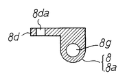
次に第1燃料分配管8について図5から図8によって説明する。
8aは図5において左右方向の側方に向けて形成された第1燃料通路ボス部であり,該第1燃料通路ボス部に以下の構成が一体形成される。
第1燃料通路ボス部8aの右端には図6において,上方に向けて第1燃料噴射弁支持ボス部8bが形成される。
又,第1燃料通路ボス部8aの右端には,他側方Xに向かって第1取付け鍔部8cが突出して形成され,左端には他側方Xに向かって第2取付け鍔部8dが突出して形成される。又,第1燃料通路ボス部8aの略中間部には,他側方Xに向かって第1燃料接続管部8eが突出して形成される。
そして,第1燃料通路ボス部8a内には,左端8fから右方に向けて第1燃料通路8gが穿設される。
又,第1燃料噴射弁支持ボス部8bの上端8baから第1燃料通路8g側に向けて第1噴射弁挿入孔8hが穿設され,この第1噴射弁挿入孔8hの底部は第1燃料通路8gに連絡される。
又,第1燃料接続管部8eの先端8eaから第1燃料通路8gに向けて第1燃料接続路8kが穿設される。
更に,第1取付け鍔部8cには取付け孔8caが貫通して穿設されるとともに第2取付け鍔部8dに取付け孔8daが貫通して穿設される。
Next, the first
A first fuel injection valve
Further, a
Their to, in the first fuel
A first injection
Further, a first
Further, an attachment hole 8ca is formed through the
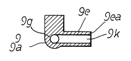
次に第2燃料分配管9について図9から図12によって説明する。
9aは図9において左右方向の側方に向けて形成された第2燃料通路ボス部であり,該第2燃料通路ボス部に以下の構成が一体形成される。
第2燃料通路ボス部9aの左端には図10において,上方に向けて第2燃料噴射弁支持ボス部9bが形成される。
又,第2燃料通路ボス部9aの左端には,一側方Yに向かって第3取付け鍔部9cが突出して形成され,右端には一側方Yに向かって第4取付け鍔部9dが突出して形成される。又,第2燃料通路ボス部9aの略中間部には,一側方Yに向かって第2燃料接続管部9eが突出して形成される。
そして,第2燃料通路ボス部9a内には,左端9fから右方に向けて第2燃料通路9gが穿設される。
又,第2燃料噴射弁支持ボス部9bの上端9baから第2燃料通路9g側に向けて第2噴射弁挿入孔9hが穿設され,この第2噴射弁挿入孔9hの底部は第2燃料通路9gに連絡される。
又,第2燃料接続管部9eの先端9eaから第2燃料通路9gに向けて第2燃料接続路9kが穿設される。
更に,第3取付け鍔部9cには取付け孔9caが貫通して穿設されるとともに第4取付け鍔部9dに取付け孔9daが貫通して穿設される。
そして,第1燃料通路ボス部8aの左端8fに開口する第1燃料通路8gの開口部8gaに燃料流入管10が接続され,第2燃料通路ボス部9aの左端9fに開口する第2燃料通路9gの開口部9gaはプラグ11によって閉塞される。
Next, the second
In the left end of the second
Further, a
Their to, in the second fuel
A second injection
Further, a second fuel connection path 9k is formed from the tip 9ea of the second fuel connection pipe portion 9e toward the
Further, a mounting hole 9ca is drilled through the
The
そして,前記,第1及び第2燃料分配管8,9は以下によって第1,第2スロットルボデー1,3にネジ止めされる。
第1燃料分配管8は,第1スロットルボデー1の一側壁1a,第2スロットルボデー3の一側壁3eに臨んで配置され,第1燃料分配管8の第1取付け鍔部8cが第1スロットルボデー1の第1取付け段部1c上に配置され,取付け孔8caを介して第1取付け鍔部8cが第1スロットルボデー1に螺着される。
又,第1燃料分配管8の第2取付け鍔部8dが第2スロットルボデー3の一側壁3eから一側方Yに向かってのびる鍔部3fに当接して配置され,取付け孔8daを介して第2取付け鍔部8dが第1スロットルボデー1にネジ止め。
以上によって第1燃料分配管8が第1スロットルボデー1の一側壁1a及び第2スロットルボデー3の一側壁3eにネジ止めされるもので,このとき第1燃料噴射弁J1の噴射側先端部J1aが第1噴射弁挿入孔1b内に挿入して配置され,流入側端部J1bが第1燃料分配管8の第1噴射弁挿入孔8h内に挿入して配置される。
以上によると,第1燃料噴射弁J1は第1燃料分配管8と第1スロットルボデー1とにより挟持される。(これは図2に示される)又,第1燃料接続管部8eは他側方Xに向かい,且つ絞り弁軸6より上流側の第1,第2スロットルボディ1,3の中間部に向かって配置される。(尚,上記上流とは吸気通路2,4に向ける空気流れの上流側をいう)
第2燃料分配管9は,第1スロットルボデー1の他側壁1h,第2スロットルボデー3の他側壁3aに臨んで配置され,第2燃料分配管9の第3取付け鍔部9cが第2スロットルボデー3の第2取付け段部3c上に配置され,取付け孔9caを介して第3取付け鍔部9cが第2スロットルボデー3にネジ止めされる。
又,第2燃料分配管9の第4取付け鍔部9dが第1スロットルボデー1の他側壁1hから他側方Xに向かってのびる鍔部1kに当接して配置され,取付け孔9daを介して第4取付け鍔部9dが第1スロットルボデー1にネジ止めされる。
以上によって第2燃料分配管9が第1スロットルボデー1の他側壁1h及び第2スロットルボデー3の他側壁3aにネジ止めされるもので,このとき第2燃料噴射弁J2の噴射側先端部J2aが第2噴射弁挿入孔3b内に挿入して配置され,流入側端部J2bが第2燃料分配管9の第2噴射弁挿入孔9h内に挿入して配置される。
以上によると,第2燃料噴射弁J2は第2燃料分配管9と第2スロットルボデー3とにより挟持される。(これは図3に示される)又,第2燃料接続管部9eは一側方Yに向かい,且つ絞り弁軸6より上流側の第1,第2スロットルボディ1,3の中間部に向かって配置される。
The first and second
The first
Further, the
Thus, the first
According to the above, the first fuel injection valve J1 is sandwiched between the first
The second
Further, the
Thus, the second
According to the above, the second fuel injection valve J2 is sandwiched between the second
次いで,第1燃料分配管8の他側方Xにのびる第1燃料接続管部8eと第2燃料分配管9の一側方Yにのびる第2燃料接続管部9eと,が燃料連結管13によって接続される。尚,燃料連結管13の一側方Yの端部外周は,締結部材14aによって第1燃料接続管部8eに締結され,燃料連結管13の他側方Xの端部外周は,締結部材14bによって第2燃料接続管部9eに締結される。
Next, the first
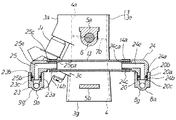
以上によってV型機関用のスロットルボデーが形成され,かかるスロットルボデーがVバンク内に配置される。
そして,図示せぬ燃料ポンプによって昇圧された燃料は,燃料流入管10より第1燃料分配管8の第1燃料通路8g内へ供給され,第1燃料通路8g内の燃料の一部は,第1噴射弁挿入孔8hから第1燃料噴射弁J1へ供給され,その噴射側先端部J1aから第1絞り弁7aより下流側の第1吸気通路2aに向けて噴射供給される。
一方,第1燃料通路8g内の燃料の他部は,第1燃料接続路8k,燃料連結管13,第2燃料接続路9kを介して第2燃料分配管9の第2燃料通路9gへ供給され,この第2燃料通路9gは,第2噴射弁挿入孔9hから第2燃料噴射弁J2へ供給され,その噴射側先端部J2aから第2絞り弁7bより下流側の第2吸気通路4a内に向けて噴射供給される。
Thus, a throttle body for a V-type engine is formed, and the throttle body is disposed in the V bank.
The fuel boosted by a fuel pump (not shown) is supplied from the
On the other hand, the other part of the fuel in the
以上の如き,吸気装置によると,燃料連結管13は,絞り弁軸6より上流側の第1及び第2スロットルボディ1,3の間に配置される。したがって,燃料連結管13がV型機関の他の構成部分と干渉することがなく,通路設計の自由度を向上できる。
又,燃料連結管13をV型機関の気筒より離して配置することができるもので,気筒の熱を受けて燃料連結管13内の燃料が加熱されて上昇することを抑止できる。
又,燃料連結管13が,第1,第2スロットルボデー1,3の対向壁1d,3d間に配置され,その外周部分が対向壁1d,3dによって保護されるので,二輪車に搭載された際,燃料連結管13が外部の障害物に接触して外れたりすることがなく,又,燃料連結管13が直接,外側方に露出することがなく,二輪車の外観性を向上できる。
更に,第1燃料接続管部8eが第1燃料分配管8に一体形成され,第2燃料接続管部9eが第2燃料分配管9に一体形成されるので,各燃料接続管部8e,9eを,それぞれのスロットルボデー1,3に個々に取付ける必要がなく,これによって部品点数の削減と取付け作業を低減できる。
As described above, according to the intake device , the
Further, the
Further, since the
Further, since the first
次に本発明の第2の実施例について説明する。
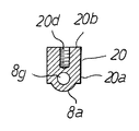
図13から図17に基づき第1燃料分配管20について説明する。
図5から図8に示される第1燃料分配管8との相違部分について説明し,同一構造部分は同一符号を使用して説明を省略する。
20aは,第1燃料通路ボス部8aより上方に向けて突出形成される第1燃料接続管部取付けボス部であり,その上端に平坦面をなす第1取付け面20bが形成される。
そしてこの第1取付け面20bには第1燃料接続管部挿入孔20cとネジ孔20dが穿設されて開口する。
そして,前記第1燃料接続管部挿入孔の底部は第1燃料通路8gに連絡される。
Next, a second embodiment of the present invention will be described.
The first
Differences from the first
The
The bottom of the first fuel connection pipe insertion hole communicates with the
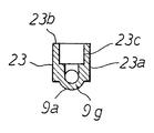
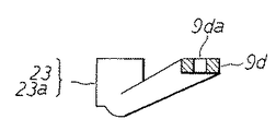
又,図18から図22により第2燃料分配管23について説明する。
図9から図12に示される第2燃料分配管9との相違部分について説明し,同一構造部分は同一符号を使用して説明を省略する。
23aは,第2燃料通路ボス部9aより上方に向けて突出形成される第2燃料接続管部取付けボス部であり,その上端に平坦面をなす第2取付け面23bが形成される。
そしてこの第2取付け面23bには第2燃料接続管部挿入孔23cとネジ孔23dが穿設されて開口する。
そして,前記第2燃料接続管部挿入孔の底部は第2燃料通路9gに連絡される。
The second
Different parts from the second
A second fuel connection pipe
The bottom of the second fuel connection pipe insertion hole communicates with the
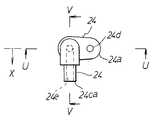
次に第1燃料接続管部取付けボス部20aに取着される第1燃料接続管部24について図23から図25によって説明する。
第1燃料接続管部24は,平坦状をなす鍔部24aと鍔部24aの下面より下方に向かって突出する第1挿入ボス24bと,鍔部24aより他側方Xに向かって突出する第1燃料引出し管部24cとにより形成され,鍔部24aには取付け孔24dが貫通して穿設され,更に第1挿入ボス24bの下端24baから第1燃料引出し管部24cの先端24caに向けて第1燃料接続路24eが穿設される。
Next, the first fuel
The first fuel
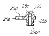
次に第2燃料接続管部取付けボス部23aに取着される第2燃料接続管部25について図26から図28によって説明する。
第2燃料接続管部25は,平坦状をなす鍔部25a,鍔部25aの下面より下方に向かって突出する第2挿入ボス25bと,鍔部25aより一側方Yに向かって突出する第2燃料引出し管部25cとにより形成され,鍔部25aには取付け孔25dが貫通して穿設され,更に第2挿入ボス25bの下端25baから第2燃料引出し管部25cの先端25caに向けて第2燃料接続路25eが穿設される。
Next, the second fuel
The second fuel
かかる第1燃料分配管20は,第1取付け鍔部8cの取付け孔8caを介して第1スロットルボデー1の一側壁1aにネジ止めされ,第2取付け鍔部8dの取付け孔8daを介して第2スロットルボデー3の一側壁3eにネジ止めされる。
尚,第1燃料噴射弁J1は,前述の如く第1燃料分配管の第1噴射弁挿入孔8hと第1スロットルボデー1の第1噴射弁先端挿入孔1bとによって支持される。
Such first
The first fuel injection valve J1 is supported by the first injection
又,第2燃料分配管23は,第3取付け鍔部9cの取付け孔9caを介して第2スロットルボデー3の他側壁3aにネジ止めされ,第4取付け鍔部9dの取付け孔9daを介して第1スロットルボデー3の他側壁1hにネジ止めされる。
尚,第2燃料噴射弁J2は,前述の如く第2燃料分配管23の第2噴射弁挿入孔9hと第2スロットルボデー3の第2噴射弁先端挿入孔3bとによって支持される。
The second
The second fuel injection valve J2 is supported by the second injection
一方,第1燃料接続管部24の第1燃料引出し管部24cと,第2燃料接続管部25の第2燃料引出し管部25cとは予め燃料連結管13をもって接続することができ,燃料連結管13の両端は前記実施例と同様に,締結部材14a,14bによって締結される。
On the other hand, the first fuel
そして,前記燃料連結管13の一端が接続された第1燃料接続管部24の第1挿入ボス24bが第1燃料分配管20の第1燃料接続管部挿入孔20c内に挿入配置されるとともに鍔部24aが第1燃料接続管部取付けボス部20aの第1取付け面20b上に配置され,この状態で第1燃料接続管部24の取付け孔24dよりネジ孔20d内にネジ30が螺着される。
The
又,前記燃料連結管13の他端が接続された第2燃料接続管部25の第2挿入ボス部25bが第2燃料分配管23の第2燃料接続管部挿入孔23c内に挿入配置されるとともに鍔部25aが第2燃料接続管部取付けボス部23aの第2取付け面23b上に配置され,この状態で第2燃料接続管部25の取付け孔25dよりネジ孔23d内にネジ31が螺着される。
The
かかる第2の実施例によると,第1,第2燃料接続管部24,25に予め燃料連結管13を配置したので,特に燃料連結管13の取付け作業性を大きく向上できた。
又,燃料連結管13のメンテナンス時にあっては第1,第2燃料接続管部24,25を第1,第2燃料分配管20,23より取外せばよく,第1,第2燃料分配管20,23は第1,第2スロットルボデー1,3に取着したままでよいので,燃料連結管13のメンテナンス作業性を大きく向上できたものである。
According to the second embodiment, since the
Further, during maintenance of the
ここで再び図5に戻って第1燃料分配管8について説明すると,第1取付け鍔部8cの取付け孔8caを,第1燃料接続管部8eの右側方に配置するとともに第1噴射弁挿入孔8hの長手軸心線W−W上に配置し,第2取付け鍔部8dの取付け孔8daを第1燃料接続管部8eの左側方に配置することによると,第1燃料接続管部8eに燃料連結管13の一端を挿入して締結部材14aにて締結する際,第1燃料分配管8に外力が加わることに成るが,第1燃料接続管部8eの左右両端部分が固定されるので第1燃料分配管8を,第1,第2スロットルボデー1,3に対して強固に固定できる。
そのうち特に第1取付け鍔部8cの取付け孔8caを第1噴射弁挿入孔8hの長手軸心線W−W上に配置したことにより第1噴射弁挿入孔8hをより一層正確に固定でき,第1燃料噴射弁Jの流入側端部J1bと第1噴射弁挿入孔8hとの気密保持性を向上できる。
Returning to FIG. 5 again, the first
Among them, in particular, the first injection
又,図9に戻って第2燃料分配管9について説明すると,第3取付け鍔部9cの取付け孔9caを,第2燃料接続管部9eの左側方に配置するとともに第2噴射弁挿入孔9hの長手軸心線Z−Z上に配置し,第4取付け鍔部9dの取付け孔9daを第2燃料接続管部9eの右側方に配置することによると,第2燃料接続管部9eに燃料連結管13の他端を挿入して締結部材14bにて締結する際,第2燃料分配管9に外力が加わることに成るが,第2燃料接続管部9eの左右両端部分が固定されるので第2燃料分配管9を,第1,第2スロットルボデー1,3に対して強固に固定できる。
そのうち特に第3取付け鍔部9cの取付け孔9caを第2噴射弁挿入孔9hの長手軸心線Z−Z上に配置したことにより第2噴射弁挿入孔9hをより一層正確に固定でき,第2燃料噴射弁J2の流入側端部J2bと第2噴射弁挿入孔9hとの気密保持性を向上できる。
Returning to FIG. 9, the second
In particular, the second injection
1 第1スロットルボデー
1a 一側壁
2 第1吸気通路
4 第2吸気通路
3 第2スロットルボデー
3a 他側壁
6 絞り弁軸
7a 第1絞り弁
7b 第1絞り弁
8 第1燃料分配管
8a 第1燃料通路ボス部
8b 第1燃料噴射弁支持ボス部
8c 第1取付け鍔部
8d 第2取付け鍔部
8e 第1燃料接続管部
8g 第1燃料通路
8h 第1噴射弁挿入孔
8k 第1燃料接続路
9 第2燃料分配管
9a 第2燃料通路ボス部
9b 第2燃料噴射弁支持ボス部
9c 第3取付け鍔部
9d 第4取付け鍔部
9e 第2燃料接続管部
9g 第2燃料通路
9k 第2燃料接続路
10 燃料流入管
13 燃料連結管
20a 第1燃料接続管取付けボス部
23a 第2燃料接続管取付けボス部
24b 第1挿入ボス
25b 第2挿入ボス
1 First throttle body
1a One side wall
2 First intake passage
4
3a Other side wall
6 Throttle valve shaft
7a First throttle valve
7b
20a First fuel connection pipe mounting boss
23a Second fuel connection pipe mounting boss
24b First insertion boss
25b Second insertion boss
Claims (3)
前記絞り弁軸(6)を挟むようにして第1及び第2スロットルボディ(1,3)の一側方と他側方とに第1及び第2燃料分配管(8,9)を配設し, First and second fuel distribution pipes (8, 9) are disposed on one side and the other side of the first and second throttle bodies (1, 3) so as to sandwich the throttle valve shaft (6),
前記第1燃料分配管(8)を,前記絞り弁軸(6)に沿って延びる第1燃料通路ボス部(8a)と,この第1燃料通路ボス部(8a)の外周より突出して第1燃料噴射弁(J1)の流入側端部(J1b)に嵌合される第1燃料噴射弁支持ボス部(8b)と,第1燃料通路ボス部(8a)の外周よりそれぞれ突出して第1及び第2スロットルボディ(1,3)にそれぞれネジ止めされる第1及び第2取付け鍔部(8c,8d)と,第1燃料通路ボス部(8a)とで構成し, The first fuel distribution pipe (8) protrudes from the outer periphery of the first fuel passage boss (8a) and the first fuel passage boss (8a) extending along the throttle valve shaft (6). A first fuel injection valve support boss portion (8b) fitted to an inflow side end portion (J1b) of the fuel injection valve (J1) and a first fuel passage boss portion (8a) projecting from the outer periphery respectively. The first and second mounting flanges (8c, 8d) screwed to the second throttle body (1, 3), respectively, and the first fuel passage boss (8a),
また前記第2燃料分配管(9)を,絞り弁軸(6)に沿って延びる第2燃料通路ボス部(9a)と,この第2燃料通路ボス部(9a)の外周より突出して第2燃料噴射弁(J2)の流入側端部(J2b)に嵌合される第2燃料噴射弁支持ボス部(9b)と,第2燃料通路ボス部(9a)の外周よりそれぞれ突出して第1及び第2スロットルボディ(1,3)にそれぞれネジ止めされる第3及び第4取付け鍔部(9c,9d)とで構成し, The second fuel distribution pipe (9) protrudes from the outer periphery of the second fuel passage boss (9a) and the second fuel passage boss (9a) extending along the throttle valve shaft (6). The second fuel injection valve support boss portion (9b) fitted to the inflow side end portion (J2b) of the fuel injection valve (J2) and the outer periphery of the second fuel passage boss portion (9a) respectively protrude from the first and The third throttle body (1, 3) and the third and fourth mounting flanges (9c, 9d) respectively screwed to the second throttle body (1, 3),
前記第1燃料通路ボス部(8a)には,燃料ポンプに連なる燃料流入管(10)を接続する一方,前記第1及び第2燃料通路ボス部(8a,9a)間を,前記絞り弁軸(6)より上流側の第1及び第2スロットルボディ(1,3)の間に配置される燃料連結管(13)を介して接続し,燃料ポンプの吐出燃料を,前記第1燃料通路ボス部(8a)及び前記第1燃料噴射弁支持ボス部(8b)を通して第1燃料噴射弁(J1)に供給し,また前記第1燃料通路ボス部(8a),前記燃料連結管(13),第2燃料通路ボス部(9a)及び第2燃料噴射弁支持ボス部(9b)を通して第2燃料噴射弁(J2)に供給するようにしたことを特徴とする,V型機関用の吸気装置。 A fuel inflow pipe (10) connected to a fuel pump is connected to the first fuel passage boss (8a), while the throttle valve shaft is connected between the first and second fuel passage bosses (8a, 9a). (6) Connected via a fuel connection pipe (13) disposed between the first and second throttle bodies (1, 3) on the upstream side of the first fuel passage boss. The first fuel injection valve (J1) through the portion (8a) and the first fuel injection valve support boss portion (8b), the first fuel passage boss portion (8a), the fuel connection pipe (13), An intake device for a V-type engine, characterized in that it is supplied to the second fuel injection valve (J2) through the second fuel passage boss (9a) and the second fuel injection valve support boss (9b).
前記第1及び第2燃料通路ボス部(9a)に,前記燃料連結管(13)が接続される第1及び第2燃料接続管部(8e,9e)を一体に形成したことを特徴とする,V型機関用の吸気装置。 The first and second fuel connection pipe parts (8e, 9e) to which the fuel connection pipe (13) is connected are integrally formed with the first and second fuel passage boss parts (9a). , Intake device for V-type engine.
前記燃料連結管(13)の両端に,前記第1及び第2燃料通路ボス部(8a,9a)にそれぞれネジ止めされる第1及び第2燃料接続管部(9e)を接続し, First and second fuel connection pipe portions (9e) screwed to the first and second fuel passage boss portions (8a, 9a) are connected to both ends of the fuel connection pipe (13),
前記第1燃料通路ボス部(8a)及び第1燃料接続管部(8e)に,互いに嵌合して第1燃料通路ボス部(8a)及び第1燃料接続管部(8e)間を連通する第1燃料接続管部取付けボス部(20a)及び第1挿入ボス(24b)をそれぞれ形成し, The first fuel passage boss portion (8a) and the first fuel connection pipe portion (8e) are fitted to each other to communicate between the first fuel passage boss portion (8a) and the first fuel connection pipe portion (8e). Forming a first fuel connection pipe part mounting boss part (20a) and a first insertion boss (24b),
また前記第2燃料通路ボス部(9a)及び第2燃料接続管部(9e)に,互いに嵌合して第2燃料通路ボス部(9a)及び第2燃料接続管部(9e)間を連通する第2燃料接続管部取付けボス部(23a)及び第2挿入ボス(25b)をそれぞれ形成したことを特徴とする,V型機関用の吸気装置。 The second fuel passage boss (9a) and the second fuel connection pipe (9e) are fitted to each other so as to communicate between the second fuel passage boss (9a) and the second fuel connection pipe (9e). An intake device for a V-type engine, wherein a second fuel connection pipe portion mounting boss portion (23a) and a second insertion boss (25b) are formed.
Priority Applications (2)
| Application Number | Priority Date | Filing Date | Title |
|---|---|---|---|
| JP2005010501A JP4430552B2 (en) | 2005-01-18 | 2005-01-18 | Intake device for V-type engine |
| US11/333,270 US7152577B2 (en) | 2005-01-18 | 2006-01-18 | Throttle body for V-type engine |
Applications Claiming Priority (1)
| Application Number | Priority Date | Filing Date | Title |
|---|---|---|---|
| JP2005010501A JP4430552B2 (en) | 2005-01-18 | 2005-01-18 | Intake device for V-type engine |
Publications (2)
| Publication Number | Publication Date |
|---|---|
| JP2006200382A JP2006200382A (en) | 2006-08-03 |
| JP4430552B2 true JP4430552B2 (en) | 2010-03-10 |
Family
ID=36682566
Family Applications (1)
| Application Number | Title | Priority Date | Filing Date |
|---|---|---|---|
| JP2005010501A Expired - Fee Related JP4430552B2 (en) | 2005-01-18 | 2005-01-18 | Intake device for V-type engine |
Country Status (2)
| Country | Link |
|---|---|
| US (1) | US7152577B2 (en) |
| JP (1) | JP4430552B2 (en) |
Families Citing this family (12)
| Publication number | Priority date | Publication date | Assignee | Title |
|---|---|---|---|---|
| JP4334493B2 (en) * | 2005-03-17 | 2009-09-30 | 株式会社ケーヒン | Fuel supply pipe structure in a multiple throttle body with two fuel injection valves |
| EP1884658B1 (en) * | 2006-08-03 | 2011-06-08 | Keihin Corporation | Fuel distribution pipe structure in multiple throttle body |
| DE102007007715A1 (en) * | 2007-02-16 | 2008-08-21 | Robert Bosch Gmbh | Fuel supply system for internal combustion engine of motor vehicle, has fuel distributor for distribution of fuel from fuel line with two branch lines, where connector connects fuel distributor with fuel line or branch line |
| JP4902401B2 (en) * | 2007-03-20 | 2012-03-21 | 株式会社ケーヒン | Throttle body for internal combustion engine |
| EP1978235B1 (en) | 2007-04-06 | 2011-10-19 | Keihin Corporation | Throttle body in fuel injection apparatus |
| JP4751366B2 (en) * | 2007-05-17 | 2011-08-17 | 株式会社ケーヒン | Twin barrel type double throttle body in an internal combustion engine for motorcycles |
| JP2009092020A (en) * | 2007-10-10 | 2009-04-30 | Yamaha Motor Co Ltd | Engine unit and vehicle equipped with the same |
| JP5014227B2 (en) * | 2008-03-28 | 2012-08-29 | 本田技研工業株式会社 | Fuel distribution device for V-type engine |
| JP5078700B2 (en) * | 2008-03-28 | 2012-11-21 | 本田技研工業株式会社 | Multi-cylinder engine intake system |
| JP5577887B2 (en) * | 2010-06-29 | 2014-08-27 | スズキ株式会社 | V-type engine fuel supply system |
| JP6256918B2 (en) * | 2014-09-30 | 2018-01-10 | 本田技研工業株式会社 | Injector assembly |
| CN109252966B (en) * | 2018-10-25 | 2024-06-04 | 上海世德子汽车零部件有限公司 | Valve core control module of automobile engine throttle valve |
Family Cites Families (5)
| Publication number | Priority date | Publication date | Assignee | Title |
|---|---|---|---|---|
| JP2760589B2 (en) * | 1989-08-25 | 1998-06-04 | 本田技研工業株式会社 | Air-fuel ratio control device for V-type internal combustion engine |
| JP3002210B2 (en) * | 1989-10-19 | 2000-01-24 | ヤマハ発動機株式会社 | Intake device for two-cycle V-type engine |
| JP3286957B2 (en) | 1992-03-06 | 2002-05-27 | ヤマハ発動機株式会社 | Fuel supply system for motorcycle engine and V-type engine |
| JP2002364467A (en) * | 2001-06-08 | 2002-12-18 | Yamaha Motor Co Ltd | Engine intake system |
| JP4446835B2 (en) * | 2004-08-24 | 2010-04-07 | 本田技研工業株式会社 | V-type engine intake system for vehicles |
-
2005
- 2005-01-18 JP JP2005010501A patent/JP4430552B2/en not_active Expired - Fee Related
-
2006
- 2006-01-18 US US11/333,270 patent/US7152577B2/en not_active Expired - Fee Related
Also Published As
| Publication number | Publication date |
|---|---|
| JP2006200382A (en) | 2006-08-03 |
| US7152577B2 (en) | 2006-12-26 |
| US20060157021A1 (en) | 2006-07-20 |
Similar Documents
| Publication | Publication Date | Title |
|---|---|---|
| JP4430552B2 (en) | Intake device for V-type engine | |
| EP2599989B1 (en) | Air-intake device | |
| JP4965513B2 (en) | Intake manifold | |
| US7086364B2 (en) | Intake system for V-engine | |
| JP2019044644A (en) | Intake system | |
| US9315228B2 (en) | Saddle type vehicle | |
| US8459239B2 (en) | Intake device for multicylinder engine | |
| JP5394202B2 (en) | Intake manifold | |
| US9482197B2 (en) | Fuel supply structure in vehicle engine | |
| JP4074941B2 (en) | Mounting structure of fuel injection valve | |
| EP1903211B1 (en) | Fuel supply system for engine | |
| JP5092805B2 (en) | Fuel supply device for multi-cylinder internal combustion engine | |
| JP2019157801A (en) | Internal combustion engine | |
| JP2011231657A (en) | Stay structure of resin intake manifold | |
| JPH09222052A (en) | Intake manifold | |
| JP2007218159A (en) | Fuel distribution piping structure in multiple throttle bodies | |
| JP5782728B2 (en) | Intake structure of internal combustion engine | |
| JP7400547B2 (en) | Installation structure of EGR valve in engine | |
| JP5738064B2 (en) | Intake device for multi-cylinder internal combustion engine | |
| US9316138B2 (en) | Saddle type vehicle | |
| JP2006063954A (en) | V-type engine intake system | |
| JP2019108865A (en) | Intake manifold of internal combustion engine | |
| JP2013144929A (en) | Purge gas introduction path structure | |
| JP5681420B2 (en) | Engine fuel injector | |
| JP2009036158A (en) | Throttle body for V type engine |
Legal Events
| Date | Code | Title | Description |
|---|---|---|---|
| A621 | Written request for application examination |
Free format text: JAPANESE INTERMEDIATE CODE: A621 Effective date: 20071122 |
|
| A131 | Notification of reasons for refusal |
Free format text: JAPANESE INTERMEDIATE CODE: A131 Effective date: 20090113 |
|
| RD03 | Notification of appointment of power of attorney |
Free format text: JAPANESE INTERMEDIATE CODE: A7423 Effective date: 20090204 |
|
| A521 | Request for written amendment filed |
Free format text: JAPANESE INTERMEDIATE CODE: A523 Effective date: 20090313 |
|
| A131 | Notification of reasons for refusal |
Free format text: JAPANESE INTERMEDIATE CODE: A131 Effective date: 20090729 |
|
| A521 | Request for written amendment filed |
Free format text: JAPANESE INTERMEDIATE CODE: A523 Effective date: 20090925 |
|
| TRDD | Decision of grant or rejection written | ||
| A01 | Written decision to grant a patent or to grant a registration (utility model) |
Free format text: JAPANESE INTERMEDIATE CODE: A01 Effective date: 20091202 |
|
| A01 | Written decision to grant a patent or to grant a registration (utility model) |
Free format text: JAPANESE INTERMEDIATE CODE: A01 |
|
| A61 | First payment of annual fees (during grant procedure) |
Free format text: JAPANESE INTERMEDIATE CODE: A61 Effective date: 20091217 |
|
| FPAY | Renewal fee payment (event date is renewal date of database) |
Free format text: PAYMENT UNTIL: 20121225 Year of fee payment: 3 |
|
| R150 | Certificate of patent or registration of utility model |
Free format text: JAPANESE INTERMEDIATE CODE: R150 Ref document number: 4430552 Country of ref document: JP Free format text: JAPANESE INTERMEDIATE CODE: R150 |
|
| FPAY | Renewal fee payment (event date is renewal date of database) |
Free format text: PAYMENT UNTIL: 20121225 Year of fee payment: 3 |
|
| FPAY | Renewal fee payment (event date is renewal date of database) |
Free format text: PAYMENT UNTIL: 20131225 Year of fee payment: 4 |
|
| R250 | Receipt of annual fees |
Free format text: JAPANESE INTERMEDIATE CODE: R250 |
|
| R250 | Receipt of annual fees |
Free format text: JAPANESE INTERMEDIATE CODE: R250 |
|
| R250 | Receipt of annual fees |
Free format text: JAPANESE INTERMEDIATE CODE: R250 |
|
| R250 | Receipt of annual fees |
Free format text: JAPANESE INTERMEDIATE CODE: R250 |
|
| R250 | Receipt of annual fees |
Free format text: JAPANESE INTERMEDIATE CODE: R250 |
|
| R250 | Receipt of annual fees |
Free format text: JAPANESE INTERMEDIATE CODE: R250 |
|
| R250 | Receipt of annual fees |
Free format text: JAPANESE INTERMEDIATE CODE: R250 |
|
| R250 | Receipt of annual fees |
Free format text: JAPANESE INTERMEDIATE CODE: R250 |
|
| R250 | Receipt of annual fees |
Free format text: JAPANESE INTERMEDIATE CODE: R250 |
|
| S111 | Request for change of ownership or part of ownership |
Free format text: JAPANESE INTERMEDIATE CODE: R313111 |
|
| R350 | Written notification of registration of transfer |
Free format text: JAPANESE INTERMEDIATE CODE: R350 |
|
| R250 | Receipt of annual fees |
Free format text: JAPANESE INTERMEDIATE CODE: R250 |
|
| R250 | Receipt of annual fees |
Free format text: JAPANESE INTERMEDIATE CODE: R250 |
|
| LAPS | Cancellation because of no payment of annual fees |