JP4429909B2 - Intervertebral prosthesis - Google Patents
Intervertebral prosthesis Download PDFInfo
- Publication number
- JP4429909B2 JP4429909B2 JP2004537345A JP2004537345A JP4429909B2 JP 4429909 B2 JP4429909 B2 JP 4429909B2 JP 2004537345 A JP2004537345 A JP 2004537345A JP 2004537345 A JP2004537345 A JP 2004537345A JP 4429909 B2 JP4429909 B2 JP 4429909B2
- Authority
- JP
- Japan
- Prior art keywords
- prosthesis
- core
- plate
- plates
- peg
- Prior art date
- Legal status (The legal status is an assumption and is not a legal conclusion. Google has not performed a legal analysis and makes no representation as to the accuracy of the status listed.)
- Expired - Fee Related
Links
Images


Classifications
-
- A—HUMAN NECESSITIES
- A61—MEDICAL OR VETERINARY SCIENCE; HYGIENE
- A61F—FILTERS IMPLANTABLE INTO BLOOD VESSELS; PROSTHESES; DEVICES PROVIDING PATENCY TO, OR PREVENTING COLLAPSING OF, TUBULAR STRUCTURES OF THE BODY, e.g. STENTS; ORTHOPAEDIC, NURSING OR CONTRACEPTIVE DEVICES; FOMENTATION; TREATMENT OR PROTECTION OF EYES OR EARS; BANDAGES, DRESSINGS OR ABSORBENT PADS; FIRST-AID KITS
- A61F2/00—Filters implantable into blood vessels; Prostheses, i.e. artificial substitutes or replacements for parts of the body; Appliances for connecting them with the body; Devices providing patency to, or preventing collapsing of, tubular structures of the body, e.g. stents
- A61F2/02—Prostheses implantable into the body
- A61F2/30—Joints
- A61F2/44—Joints for the spine, e.g. vertebrae, spinal discs
- A61F2/442—Intervertebral or spinal discs, e.g. resilient
- A61F2/4425—Intervertebral or spinal discs, e.g. resilient made of articulated components
-
- A—HUMAN NECESSITIES
- A61—MEDICAL OR VETERINARY SCIENCE; HYGIENE
- A61F—FILTERS IMPLANTABLE INTO BLOOD VESSELS; PROSTHESES; DEVICES PROVIDING PATENCY TO, OR PREVENTING COLLAPSING OF, TUBULAR STRUCTURES OF THE BODY, e.g. STENTS; ORTHOPAEDIC, NURSING OR CONTRACEPTIVE DEVICES; FOMENTATION; TREATMENT OR PROTECTION OF EYES OR EARS; BANDAGES, DRESSINGS OR ABSORBENT PADS; FIRST-AID KITS
- A61F2/00—Filters implantable into blood vessels; Prostheses, i.e. artificial substitutes or replacements for parts of the body; Appliances for connecting them with the body; Devices providing patency to, or preventing collapsing of, tubular structures of the body, e.g. stents
- A61F2/02—Prostheses implantable into the body
- A61F2/30—Joints
- A61F2/30767—Special external or bone-contacting surface, e.g. coating for improving bone ingrowth
- A61F2/30771—Special external or bone-contacting surface, e.g. coating for improving bone ingrowth applied in original prostheses, e.g. holes or grooves
-
- A—HUMAN NECESSITIES
- A61—MEDICAL OR VETERINARY SCIENCE; HYGIENE
- A61F—FILTERS IMPLANTABLE INTO BLOOD VESSELS; PROSTHESES; DEVICES PROVIDING PATENCY TO, OR PREVENTING COLLAPSING OF, TUBULAR STRUCTURES OF THE BODY, e.g. STENTS; ORTHOPAEDIC, NURSING OR CONTRACEPTIVE DEVICES; FOMENTATION; TREATMENT OR PROTECTION OF EYES OR EARS; BANDAGES, DRESSINGS OR ABSORBENT PADS; FIRST-AID KITS
- A61F2/00—Filters implantable into blood vessels; Prostheses, i.e. artificial substitutes or replacements for parts of the body; Appliances for connecting them with the body; Devices providing patency to, or preventing collapsing of, tubular structures of the body, e.g. stents
- A61F2/02—Prostheses implantable into the body
- A61F2/30—Joints
- A61F2/46—Special tools or methods for implanting or extracting artificial joints, accessories, bone grafts or substitutes, or particular adaptations therefor
- A61F2/4603—Special tools or methods for implanting or extracting artificial joints, accessories, bone grafts or substitutes, or particular adaptations therefor for insertion or extraction of endoprosthetic joints or of accessories thereof
- A61F2/4611—Special tools or methods for implanting or extracting artificial joints, accessories, bone grafts or substitutes, or particular adaptations therefor for insertion or extraction of endoprosthetic joints or of accessories thereof of spinal prostheses
-
- A—HUMAN NECESSITIES
- A61—MEDICAL OR VETERINARY SCIENCE; HYGIENE
- A61F—FILTERS IMPLANTABLE INTO BLOOD VESSELS; PROSTHESES; DEVICES PROVIDING PATENCY TO, OR PREVENTING COLLAPSING OF, TUBULAR STRUCTURES OF THE BODY, e.g. STENTS; ORTHOPAEDIC, NURSING OR CONTRACEPTIVE DEVICES; FOMENTATION; TREATMENT OR PROTECTION OF EYES OR EARS; BANDAGES, DRESSINGS OR ABSORBENT PADS; FIRST-AID KITS
- A61F2/00—Filters implantable into blood vessels; Prostheses, i.e. artificial substitutes or replacements for parts of the body; Appliances for connecting them with the body; Devices providing patency to, or preventing collapsing of, tubular structures of the body, e.g. stents
- A61F2/02—Prostheses implantable into the body
- A61F2/30—Joints
- A61F2002/30001—Additional features of subject-matter classified in A61F2/28, A61F2/30 and subgroups thereof
- A61F2002/30003—Material related properties of the prosthesis or of a coating on the prosthesis
- A61F2002/3006—Properties of materials and coating materials
- A61F2002/3008—Properties of materials and coating materials radio-opaque, e.g. radio-opaque markers
-
- A—HUMAN NECESSITIES
- A61—MEDICAL OR VETERINARY SCIENCE; HYGIENE
- A61F—FILTERS IMPLANTABLE INTO BLOOD VESSELS; PROSTHESES; DEVICES PROVIDING PATENCY TO, OR PREVENTING COLLAPSING OF, TUBULAR STRUCTURES OF THE BODY, e.g. STENTS; ORTHOPAEDIC, NURSING OR CONTRACEPTIVE DEVICES; FOMENTATION; TREATMENT OR PROTECTION OF EYES OR EARS; BANDAGES, DRESSINGS OR ABSORBENT PADS; FIRST-AID KITS
- A61F2/00—Filters implantable into blood vessels; Prostheses, i.e. artificial substitutes or replacements for parts of the body; Appliances for connecting them with the body; Devices providing patency to, or preventing collapsing of, tubular structures of the body, e.g. stents
- A61F2/02—Prostheses implantable into the body
- A61F2/30—Joints
- A61F2002/30001—Additional features of subject-matter classified in A61F2/28, A61F2/30 and subgroups thereof
- A61F2002/30108—Shapes
- A61F2002/30199—Three-dimensional shapes
- A61F2002/302—Three-dimensional shapes toroidal, e.g. rings
-
- A—HUMAN NECESSITIES
- A61—MEDICAL OR VETERINARY SCIENCE; HYGIENE
- A61F—FILTERS IMPLANTABLE INTO BLOOD VESSELS; PROSTHESES; DEVICES PROVIDING PATENCY TO, OR PREVENTING COLLAPSING OF, TUBULAR STRUCTURES OF THE BODY, e.g. STENTS; ORTHOPAEDIC, NURSING OR CONTRACEPTIVE DEVICES; FOMENTATION; TREATMENT OR PROTECTION OF EYES OR EARS; BANDAGES, DRESSINGS OR ABSORBENT PADS; FIRST-AID KITS
- A61F2/00—Filters implantable into blood vessels; Prostheses, i.e. artificial substitutes or replacements for parts of the body; Appliances for connecting them with the body; Devices providing patency to, or preventing collapsing of, tubular structures of the body, e.g. stents
- A61F2/02—Prostheses implantable into the body
- A61F2/30—Joints
- A61F2002/30001—Additional features of subject-matter classified in A61F2/28, A61F2/30 and subgroups thereof
- A61F2002/30316—The prosthesis having different structural features at different locations within the same prosthesis; Connections between prosthetic parts; Special structural features of bone or joint prostheses not otherwise provided for
- A61F2002/30329—Connections or couplings between prosthetic parts, e.g. between modular parts; Connecting elements
- A61F2002/30331—Connections or couplings between prosthetic parts, e.g. between modular parts; Connecting elements made by longitudinally pushing a protrusion into a complementarily-shaped recess, e.g. held by friction fit
- A61F2002/30332—Conically- or frustoconically-shaped protrusion and recess
-
- A—HUMAN NECESSITIES
- A61—MEDICAL OR VETERINARY SCIENCE; HYGIENE
- A61F—FILTERS IMPLANTABLE INTO BLOOD VESSELS; PROSTHESES; DEVICES PROVIDING PATENCY TO, OR PREVENTING COLLAPSING OF, TUBULAR STRUCTURES OF THE BODY, e.g. STENTS; ORTHOPAEDIC, NURSING OR CONTRACEPTIVE DEVICES; FOMENTATION; TREATMENT OR PROTECTION OF EYES OR EARS; BANDAGES, DRESSINGS OR ABSORBENT PADS; FIRST-AID KITS
- A61F2/00—Filters implantable into blood vessels; Prostheses, i.e. artificial substitutes or replacements for parts of the body; Appliances for connecting them with the body; Devices providing patency to, or preventing collapsing of, tubular structures of the body, e.g. stents
- A61F2/02—Prostheses implantable into the body
- A61F2/30—Joints
- A61F2002/30001—Additional features of subject-matter classified in A61F2/28, A61F2/30 and subgroups thereof
- A61F2002/30316—The prosthesis having different structural features at different locations within the same prosthesis; Connections between prosthetic parts; Special structural features of bone or joint prostheses not otherwise provided for
- A61F2002/30329—Connections or couplings between prosthetic parts, e.g. between modular parts; Connecting elements
- A61F2002/30331—Connections or couplings between prosthetic parts, e.g. between modular parts; Connecting elements made by longitudinally pushing a protrusion into a complementarily-shaped recess, e.g. held by friction fit
- A61F2002/30362—Connections or couplings between prosthetic parts, e.g. between modular parts; Connecting elements made by longitudinally pushing a protrusion into a complementarily-shaped recess, e.g. held by friction fit with possibility of relative movement between the protrusion and the recess
- A61F2002/30364—Rotation about the common longitudinal axis
-
- A—HUMAN NECESSITIES
- A61—MEDICAL OR VETERINARY SCIENCE; HYGIENE
- A61F—FILTERS IMPLANTABLE INTO BLOOD VESSELS; PROSTHESES; DEVICES PROVIDING PATENCY TO, OR PREVENTING COLLAPSING OF, TUBULAR STRUCTURES OF THE BODY, e.g. STENTS; ORTHOPAEDIC, NURSING OR CONTRACEPTIVE DEVICES; FOMENTATION; TREATMENT OR PROTECTION OF EYES OR EARS; BANDAGES, DRESSINGS OR ABSORBENT PADS; FIRST-AID KITS
- A61F2/00—Filters implantable into blood vessels; Prostheses, i.e. artificial substitutes or replacements for parts of the body; Appliances for connecting them with the body; Devices providing patency to, or preventing collapsing of, tubular structures of the body, e.g. stents
- A61F2/02—Prostheses implantable into the body
- A61F2/30—Joints
- A61F2002/30001—Additional features of subject-matter classified in A61F2/28, A61F2/30 and subgroups thereof
- A61F2002/30316—The prosthesis having different structural features at different locations within the same prosthesis; Connections between prosthetic parts; Special structural features of bone or joint prostheses not otherwise provided for
- A61F2002/30329—Connections or couplings between prosthetic parts, e.g. between modular parts; Connecting elements
- A61F2002/30331—Connections or couplings between prosthetic parts, e.g. between modular parts; Connecting elements made by longitudinally pushing a protrusion into a complementarily-shaped recess, e.g. held by friction fit
- A61F2002/30362—Connections or couplings between prosthetic parts, e.g. between modular parts; Connecting elements made by longitudinally pushing a protrusion into a complementarily-shaped recess, e.g. held by friction fit with possibility of relative movement between the protrusion and the recess
- A61F2002/30369—Limited lateral translation of the protrusion within a larger recess
-
- A—HUMAN NECESSITIES
- A61—MEDICAL OR VETERINARY SCIENCE; HYGIENE
- A61F—FILTERS IMPLANTABLE INTO BLOOD VESSELS; PROSTHESES; DEVICES PROVIDING PATENCY TO, OR PREVENTING COLLAPSING OF, TUBULAR STRUCTURES OF THE BODY, e.g. STENTS; ORTHOPAEDIC, NURSING OR CONTRACEPTIVE DEVICES; FOMENTATION; TREATMENT OR PROTECTION OF EYES OR EARS; BANDAGES, DRESSINGS OR ABSORBENT PADS; FIRST-AID KITS
- A61F2/00—Filters implantable into blood vessels; Prostheses, i.e. artificial substitutes or replacements for parts of the body; Appliances for connecting them with the body; Devices providing patency to, or preventing collapsing of, tubular structures of the body, e.g. stents
- A61F2/02—Prostheses implantable into the body
- A61F2/30—Joints
- A61F2002/30001—Additional features of subject-matter classified in A61F2/28, A61F2/30 and subgroups thereof
- A61F2002/30316—The prosthesis having different structural features at different locations within the same prosthesis; Connections between prosthetic parts; Special structural features of bone or joint prostheses not otherwise provided for
- A61F2002/30329—Connections or couplings between prosthetic parts, e.g. between modular parts; Connecting elements
- A61F2002/30518—Connections or couplings between prosthetic parts, e.g. between modular parts; Connecting elements with possibility of relative movement between the prosthetic parts
- A61F2002/30528—Means for limiting said movement
-
- A—HUMAN NECESSITIES
- A61—MEDICAL OR VETERINARY SCIENCE; HYGIENE
- A61F—FILTERS IMPLANTABLE INTO BLOOD VESSELS; PROSTHESES; DEVICES PROVIDING PATENCY TO, OR PREVENTING COLLAPSING OF, TUBULAR STRUCTURES OF THE BODY, e.g. STENTS; ORTHOPAEDIC, NURSING OR CONTRACEPTIVE DEVICES; FOMENTATION; TREATMENT OR PROTECTION OF EYES OR EARS; BANDAGES, DRESSINGS OR ABSORBENT PADS; FIRST-AID KITS
- A61F2/00—Filters implantable into blood vessels; Prostheses, i.e. artificial substitutes or replacements for parts of the body; Appliances for connecting them with the body; Devices providing patency to, or preventing collapsing of, tubular structures of the body, e.g. stents
- A61F2/02—Prostheses implantable into the body
- A61F2/30—Joints
- A61F2002/30001—Additional features of subject-matter classified in A61F2/28, A61F2/30 and subgroups thereof
- A61F2002/30621—Features concerning the anatomical functioning or articulation of the prosthetic joint
- A61F2002/30649—Ball-and-socket joints
- A61F2002/30662—Ball-and-socket joints with rotation-limiting means
-
- A—HUMAN NECESSITIES
- A61—MEDICAL OR VETERINARY SCIENCE; HYGIENE
- A61F—FILTERS IMPLANTABLE INTO BLOOD VESSELS; PROSTHESES; DEVICES PROVIDING PATENCY TO, OR PREVENTING COLLAPSING OF, TUBULAR STRUCTURES OF THE BODY, e.g. STENTS; ORTHOPAEDIC, NURSING OR CONTRACEPTIVE DEVICES; FOMENTATION; TREATMENT OR PROTECTION OF EYES OR EARS; BANDAGES, DRESSINGS OR ABSORBENT PADS; FIRST-AID KITS
- A61F2/00—Filters implantable into blood vessels; Prostheses, i.e. artificial substitutes or replacements for parts of the body; Appliances for connecting them with the body; Devices providing patency to, or preventing collapsing of, tubular structures of the body, e.g. stents
- A61F2/02—Prostheses implantable into the body
- A61F2/30—Joints
- A61F2/30767—Special external or bone-contacting surface, e.g. coating for improving bone ingrowth
- A61F2/30771—Special external or bone-contacting surface, e.g. coating for improving bone ingrowth applied in original prostheses, e.g. holes or grooves
- A61F2002/30772—Apertures or holes, e.g. of circular cross section
- A61F2002/30784—Plurality of holes
- A61F2002/30785—Plurality of holes parallel
-
- A—HUMAN NECESSITIES
- A61—MEDICAL OR VETERINARY SCIENCE; HYGIENE
- A61F—FILTERS IMPLANTABLE INTO BLOOD VESSELS; PROSTHESES; DEVICES PROVIDING PATENCY TO, OR PREVENTING COLLAPSING OF, TUBULAR STRUCTURES OF THE BODY, e.g. STENTS; ORTHOPAEDIC, NURSING OR CONTRACEPTIVE DEVICES; FOMENTATION; TREATMENT OR PROTECTION OF EYES OR EARS; BANDAGES, DRESSINGS OR ABSORBENT PADS; FIRST-AID KITS
- A61F2/00—Filters implantable into blood vessels; Prostheses, i.e. artificial substitutes or replacements for parts of the body; Appliances for connecting them with the body; Devices providing patency to, or preventing collapsing of, tubular structures of the body, e.g. stents
- A61F2/02—Prostheses implantable into the body
- A61F2/30—Joints
- A61F2/30767—Special external or bone-contacting surface, e.g. coating for improving bone ingrowth
- A61F2/30771—Special external or bone-contacting surface, e.g. coating for improving bone ingrowth applied in original prostheses, e.g. holes or grooves
- A61F2002/3082—Grooves
- A61F2002/30822—Circumferential grooves
-
- A—HUMAN NECESSITIES
- A61—MEDICAL OR VETERINARY SCIENCE; HYGIENE
- A61F—FILTERS IMPLANTABLE INTO BLOOD VESSELS; PROSTHESES; DEVICES PROVIDING PATENCY TO, OR PREVENTING COLLAPSING OF, TUBULAR STRUCTURES OF THE BODY, e.g. STENTS; ORTHOPAEDIC, NURSING OR CONTRACEPTIVE DEVICES; FOMENTATION; TREATMENT OR PROTECTION OF EYES OR EARS; BANDAGES, DRESSINGS OR ABSORBENT PADS; FIRST-AID KITS
- A61F2/00—Filters implantable into blood vessels; Prostheses, i.e. artificial substitutes or replacements for parts of the body; Appliances for connecting them with the body; Devices providing patency to, or preventing collapsing of, tubular structures of the body, e.g. stents
- A61F2/02—Prostheses implantable into the body
- A61F2/30—Joints
- A61F2/30767—Special external or bone-contacting surface, e.g. coating for improving bone ingrowth
- A61F2/30771—Special external or bone-contacting surface, e.g. coating for improving bone ingrowth applied in original prostheses, e.g. holes or grooves
- A61F2002/30841—Sharp anchoring protrusions for impaction into the bone, e.g. sharp pins, spikes
-
- A—HUMAN NECESSITIES
- A61—MEDICAL OR VETERINARY SCIENCE; HYGIENE
- A61F—FILTERS IMPLANTABLE INTO BLOOD VESSELS; PROSTHESES; DEVICES PROVIDING PATENCY TO, OR PREVENTING COLLAPSING OF, TUBULAR STRUCTURES OF THE BODY, e.g. STENTS; ORTHOPAEDIC, NURSING OR CONTRACEPTIVE DEVICES; FOMENTATION; TREATMENT OR PROTECTION OF EYES OR EARS; BANDAGES, DRESSINGS OR ABSORBENT PADS; FIRST-AID KITS
- A61F2/00—Filters implantable into blood vessels; Prostheses, i.e. artificial substitutes or replacements for parts of the body; Appliances for connecting them with the body; Devices providing patency to, or preventing collapsing of, tubular structures of the body, e.g. stents
- A61F2/02—Prostheses implantable into the body
- A61F2/30—Joints
- A61F2/30767—Special external or bone-contacting surface, e.g. coating for improving bone ingrowth
- A61F2/30771—Special external or bone-contacting surface, e.g. coating for improving bone ingrowth applied in original prostheses, e.g. holes or grooves
- A61F2002/30878—Special external or bone-contacting surface, e.g. coating for improving bone ingrowth applied in original prostheses, e.g. holes or grooves with non-sharp protrusions, for instance contacting the bone for anchoring, e.g. keels, pegs, pins, posts, shanks, stems, struts
- A61F2002/30884—Fins or wings, e.g. longitudinal wings for preventing rotation within the bone cavity
-
- A—HUMAN NECESSITIES
- A61—MEDICAL OR VETERINARY SCIENCE; HYGIENE
- A61F—FILTERS IMPLANTABLE INTO BLOOD VESSELS; PROSTHESES; DEVICES PROVIDING PATENCY TO, OR PREVENTING COLLAPSING OF, TUBULAR STRUCTURES OF THE BODY, e.g. STENTS; ORTHOPAEDIC, NURSING OR CONTRACEPTIVE DEVICES; FOMENTATION; TREATMENT OR PROTECTION OF EYES OR EARS; BANDAGES, DRESSINGS OR ABSORBENT PADS; FIRST-AID KITS
- A61F2/00—Filters implantable into blood vessels; Prostheses, i.e. artificial substitutes or replacements for parts of the body; Appliances for connecting them with the body; Devices providing patency to, or preventing collapsing of, tubular structures of the body, e.g. stents
- A61F2/02—Prostheses implantable into the body
- A61F2/30—Joints
- A61F2/30767—Special external or bone-contacting surface, e.g. coating for improving bone ingrowth
- A61F2/30771—Special external or bone-contacting surface, e.g. coating for improving bone ingrowth applied in original prostheses, e.g. holes or grooves
- A61F2002/30878—Special external or bone-contacting surface, e.g. coating for improving bone ingrowth applied in original prostheses, e.g. holes or grooves with non-sharp protrusions, for instance contacting the bone for anchoring, e.g. keels, pegs, pins, posts, shanks, stems, struts
- A61F2002/30899—Protrusions pierced with apertures
-
- A—HUMAN NECESSITIES
- A61—MEDICAL OR VETERINARY SCIENCE; HYGIENE
- A61F—FILTERS IMPLANTABLE INTO BLOOD VESSELS; PROSTHESES; DEVICES PROVIDING PATENCY TO, OR PREVENTING COLLAPSING OF, TUBULAR STRUCTURES OF THE BODY, e.g. STENTS; ORTHOPAEDIC, NURSING OR CONTRACEPTIVE DEVICES; FOMENTATION; TREATMENT OR PROTECTION OF EYES OR EARS; BANDAGES, DRESSINGS OR ABSORBENT PADS; FIRST-AID KITS
- A61F2/00—Filters implantable into blood vessels; Prostheses, i.e. artificial substitutes or replacements for parts of the body; Appliances for connecting them with the body; Devices providing patency to, or preventing collapsing of, tubular structures of the body, e.g. stents
- A61F2/02—Prostheses implantable into the body
- A61F2/30—Joints
- A61F2/30767—Special external or bone-contacting surface, e.g. coating for improving bone ingrowth
- A61F2/30771—Special external or bone-contacting surface, e.g. coating for improving bone ingrowth applied in original prostheses, e.g. holes or grooves
- A61F2002/30904—Special external or bone-contacting surface, e.g. coating for improving bone ingrowth applied in original prostheses, e.g. holes or grooves serrated profile, i.e. saw-toothed
-
- A—HUMAN NECESSITIES
- A61—MEDICAL OR VETERINARY SCIENCE; HYGIENE
- A61F—FILTERS IMPLANTABLE INTO BLOOD VESSELS; PROSTHESES; DEVICES PROVIDING PATENCY TO, OR PREVENTING COLLAPSING OF, TUBULAR STRUCTURES OF THE BODY, e.g. STENTS; ORTHOPAEDIC, NURSING OR CONTRACEPTIVE DEVICES; FOMENTATION; TREATMENT OR PROTECTION OF EYES OR EARS; BANDAGES, DRESSINGS OR ABSORBENT PADS; FIRST-AID KITS
- A61F2/00—Filters implantable into blood vessels; Prostheses, i.e. artificial substitutes or replacements for parts of the body; Appliances for connecting them with the body; Devices providing patency to, or preventing collapsing of, tubular structures of the body, e.g. stents
- A61F2/02—Prostheses implantable into the body
- A61F2/30—Joints
- A61F2/44—Joints for the spine, e.g. vertebrae, spinal discs
- A61F2/442—Intervertebral or spinal discs, e.g. resilient
- A61F2/4425—Intervertebral or spinal discs, e.g. resilient made of articulated components
- A61F2002/443—Intervertebral or spinal discs, e.g. resilient made of articulated components having two transversal endplates and at least one intermediate component
-
- A—HUMAN NECESSITIES
- A61—MEDICAL OR VETERINARY SCIENCE; HYGIENE
- A61F—FILTERS IMPLANTABLE INTO BLOOD VESSELS; PROSTHESES; DEVICES PROVIDING PATENCY TO, OR PREVENTING COLLAPSING OF, TUBULAR STRUCTURES OF THE BODY, e.g. STENTS; ORTHOPAEDIC, NURSING OR CONTRACEPTIVE DEVICES; FOMENTATION; TREATMENT OR PROTECTION OF EYES OR EARS; BANDAGES, DRESSINGS OR ABSORBENT PADS; FIRST-AID KITS
- A61F2220/00—Fixations or connections for prostheses classified in groups A61F2/00 - A61F2/26 or A61F2/82 or A61F9/00 or A61F11/00 or subgroups thereof
- A61F2220/0008—Fixation appliances for connecting prostheses to the body
- A61F2220/0016—Fixation appliances for connecting prostheses to the body with sharp anchoring protrusions, e.g. barbs, pins, spikes
-
- A—HUMAN NECESSITIES
- A61—MEDICAL OR VETERINARY SCIENCE; HYGIENE
- A61F—FILTERS IMPLANTABLE INTO BLOOD VESSELS; PROSTHESES; DEVICES PROVIDING PATENCY TO, OR PREVENTING COLLAPSING OF, TUBULAR STRUCTURES OF THE BODY, e.g. STENTS; ORTHOPAEDIC, NURSING OR CONTRACEPTIVE DEVICES; FOMENTATION; TREATMENT OR PROTECTION OF EYES OR EARS; BANDAGES, DRESSINGS OR ABSORBENT PADS; FIRST-AID KITS
- A61F2220/00—Fixations or connections for prostheses classified in groups A61F2/00 - A61F2/26 or A61F2/82 or A61F9/00 or A61F11/00 or subgroups thereof
- A61F2220/0025—Connections or couplings between prosthetic parts, e.g. between modular parts; Connecting elements
- A61F2220/0033—Connections or couplings between prosthetic parts, e.g. between modular parts; Connecting elements made by longitudinally pushing a protrusion into a complementary-shaped recess, e.g. held by friction fit
-
- A—HUMAN NECESSITIES
- A61—MEDICAL OR VETERINARY SCIENCE; HYGIENE
- A61F—FILTERS IMPLANTABLE INTO BLOOD VESSELS; PROSTHESES; DEVICES PROVIDING PATENCY TO, OR PREVENTING COLLAPSING OF, TUBULAR STRUCTURES OF THE BODY, e.g. STENTS; ORTHOPAEDIC, NURSING OR CONTRACEPTIVE DEVICES; FOMENTATION; TREATMENT OR PROTECTION OF EYES OR EARS; BANDAGES, DRESSINGS OR ABSORBENT PADS; FIRST-AID KITS
- A61F2230/00—Geometry of prostheses classified in groups A61F2/00 - A61F2/26 or A61F2/82 or A61F9/00 or A61F11/00 or subgroups thereof
- A61F2230/0063—Three-dimensional shapes
- A61F2230/0065—Three-dimensional shapes toroidal, e.g. ring-shaped, doughnut-shaped
-
- A—HUMAN NECESSITIES
- A61—MEDICAL OR VETERINARY SCIENCE; HYGIENE
- A61F—FILTERS IMPLANTABLE INTO BLOOD VESSELS; PROSTHESES; DEVICES PROVIDING PATENCY TO, OR PREVENTING COLLAPSING OF, TUBULAR STRUCTURES OF THE BODY, e.g. STENTS; ORTHOPAEDIC, NURSING OR CONTRACEPTIVE DEVICES; FOMENTATION; TREATMENT OR PROTECTION OF EYES OR EARS; BANDAGES, DRESSINGS OR ABSORBENT PADS; FIRST-AID KITS
- A61F2250/00—Special features of prostheses classified in groups A61F2/00 - A61F2/26 or A61F2/82 or A61F9/00 or A61F11/00 or subgroups thereof
- A61F2250/0058—Additional features; Implant or prostheses properties not otherwise provided for
- A61F2250/0096—Markers and sensors for detecting a position or changes of a position of an implant, e.g. RF sensors, ultrasound markers
- A61F2250/0098—Markers and sensors for detecting a position or changes of a position of an implant, e.g. RF sensors, ultrasound markers radio-opaque, e.g. radio-opaque markers
-
- A—HUMAN NECESSITIES
- A61—MEDICAL OR VETERINARY SCIENCE; HYGIENE
- A61F—FILTERS IMPLANTABLE INTO BLOOD VESSELS; PROSTHESES; DEVICES PROVIDING PATENCY TO, OR PREVENTING COLLAPSING OF, TUBULAR STRUCTURES OF THE BODY, e.g. STENTS; ORTHOPAEDIC, NURSING OR CONTRACEPTIVE DEVICES; FOMENTATION; TREATMENT OR PROTECTION OF EYES OR EARS; BANDAGES, DRESSINGS OR ABSORBENT PADS; FIRST-AID KITS
- A61F2310/00—Prostheses classified in A61F2/28 or A61F2/30 - A61F2/44 being constructed from or coated with a particular material
- A61F2310/00005—The prosthesis being constructed from a particular material
- A61F2310/00011—Metals or alloys
- A61F2310/00017—Iron- or Fe-based alloys, e.g. stainless steel
-
- A—HUMAN NECESSITIES
- A61—MEDICAL OR VETERINARY SCIENCE; HYGIENE
- A61F—FILTERS IMPLANTABLE INTO BLOOD VESSELS; PROSTHESES; DEVICES PROVIDING PATENCY TO, OR PREVENTING COLLAPSING OF, TUBULAR STRUCTURES OF THE BODY, e.g. STENTS; ORTHOPAEDIC, NURSING OR CONTRACEPTIVE DEVICES; FOMENTATION; TREATMENT OR PROTECTION OF EYES OR EARS; BANDAGES, DRESSINGS OR ABSORBENT PADS; FIRST-AID KITS
- A61F2310/00—Prostheses classified in A61F2/28 or A61F2/30 - A61F2/44 being constructed from or coated with a particular material
- A61F2310/00005—The prosthesis being constructed from a particular material
- A61F2310/00011—Metals or alloys
- A61F2310/00029—Cobalt-based alloys, e.g. Co-Cr alloys or Vitallium
-
- A—HUMAN NECESSITIES
- A61—MEDICAL OR VETERINARY SCIENCE; HYGIENE
- A61F—FILTERS IMPLANTABLE INTO BLOOD VESSELS; PROSTHESES; DEVICES PROVIDING PATENCY TO, OR PREVENTING COLLAPSING OF, TUBULAR STRUCTURES OF THE BODY, e.g. STENTS; ORTHOPAEDIC, NURSING OR CONTRACEPTIVE DEVICES; FOMENTATION; TREATMENT OR PROTECTION OF EYES OR EARS; BANDAGES, DRESSINGS OR ABSORBENT PADS; FIRST-AID KITS
- A61F2310/00—Prostheses classified in A61F2/28 or A61F2/30 - A61F2/44 being constructed from or coated with a particular material
- A61F2310/00005—The prosthesis being constructed from a particular material
- A61F2310/00179—Ceramics or ceramic-like structures
-
- A—HUMAN NECESSITIES
- A61—MEDICAL OR VETERINARY SCIENCE; HYGIENE
- A61F—FILTERS IMPLANTABLE INTO BLOOD VESSELS; PROSTHESES; DEVICES PROVIDING PATENCY TO, OR PREVENTING COLLAPSING OF, TUBULAR STRUCTURES OF THE BODY, e.g. STENTS; ORTHOPAEDIC, NURSING OR CONTRACEPTIVE DEVICES; FOMENTATION; TREATMENT OR PROTECTION OF EYES OR EARS; BANDAGES, DRESSINGS OR ABSORBENT PADS; FIRST-AID KITS
- A61F2310/00—Prostheses classified in A61F2/28 or A61F2/30 - A61F2/44 being constructed from or coated with a particular material
- A61F2310/00389—The prosthesis being coated or covered with a particular material
- A61F2310/00592—Coating or prosthesis-covering structure made of ceramics or of ceramic-like compounds
- A61F2310/00856—Coating or prosthesis-covering structure made of compounds based on metal nitrides
- A61F2310/0088—Coating made of titanium nitride
Abstract
Description
(発明の背景)
本発明は、椎間プロテーゼに関する。
(Background of the Invention)
The present invention relates to an intervertebral prosthesis.
椎間板(spinal disc)に対する損傷が起こると、椎間プロテーゼを外科手術により移植して、損傷した器官を置き換えることは、公知の慣習である。この目的のためのいくつかの型のプロテーゼが公知であり、一般に使用されている。 When damage to the spinal disc occurs, it is a well-known practice to surgically implant an intervertebral prosthesis to replace the damaged organ. Several types of prostheses for this purpose are known and commonly used.
公知の椎間プロテーゼの1つの型は、商標LINK(登録商標)SB Chariteの下でWaldemar Link GmbH&Coによって販売される。このプロテーゼは、隣接する椎骨本体に対して位置し、かつ係合する、上側および下側のプロテーゼ板、およびその板の間に摩擦コアを備える。そのコアは、上側および下側の凹型に弯曲した表面を有し、その板は、そのコアの弯曲した表面と協働する、対応する凹型に弯曲したくぼみを有する。このことは、その板がそのコア上をスライドして、必要とされる脊髄の動きを発生させることを可能にする。その板における弯曲したくぼみは、環状リッジによって囲まれ、その環状リッジは、その板がコアの上をスライドする動きの制限において、そのコアの弯曲した表面の周りを囲む対向する球状チャネルに位置する。 One type of known intervertebral prosthesis is sold by Waldemar Link GmbH & Co under the trademark LINK® SB Charite. The prosthesis includes upper and lower prosthetic plates positioned and engaged with adjacent vertebral bodies, and a friction core between the plates. The core has upper and lower concavely curved surfaces, and the plate has corresponding concavely curved indentations that cooperate with the core's curved surfaces. This allows the plate to slide over the core to generate the required spinal motion. The curved indentation in the plate is surrounded by an annular ridge, which is located in an opposing spherical channel that surrounds the curved surface of the core in limiting the movement of the plate over the core. .
この型の配置はまた、EP0 560 140およびEP0 560 141(ともに、Waldemar Link GmbH&Co)において記載される。しかし、このような配置の欠点は、周辺リブおよびチャネルの設備が、その板とコアとの間のベアリング接触およびスライド接触に利用可能な領域を制限し、よって負荷がプロテーゼによって伝達され得ることである。相対的に小さなベアリング領域の結果として、少なくともそのコアが、急激な摩耗を受けやすく、比較的短い寿命を有すると考えられる。 This type of arrangement is also described in EP0 560 140 and EP0 560 141 (both Waldemar Link GmbH & Co). However, the disadvantage of such an arrangement is that the peripheral rib and channel equipment limits the area available for bearing and sliding contact between its plate and core, so that the load can be transmitted by the prosthesis. is there. As a result of the relatively small bearing area, it is believed that at least its core is susceptible to rapid wear and has a relatively short life.
EP 0 560 141はまた、そのコアの弯曲した表面がその板における細長い溝に位置する対向した細長いキー(key)を有する1つの代替的配置、およびそのプレートが、そのコアの対向する弯曲した表面における細長い溝に位置する対向した細長いキーを有する別の代替的配置を記載する。これらのキーおよび溝の配置は、1つの平面のみにおいて、そのプレートがその溝の長さの制限内でそのコアの上を自由にスライドすることを可能にする。その溝におけるキーのいくつかの横方向の役割が許容されるが、その板がそのコアの上をスライドする動きは、直交した垂直平面においてほとんど生じ得ず、このことは、この設計において重大な欠点であると考えられる。 EP 0 560 141 is also an alternative arrangement in which the curved surface of the core has opposed elongated keys located in elongated grooves in the plate, and the plate is an opposed curved surface of the core Another alternative arrangement having opposed elongated keys located in the elongated grooves is described. These key and groove arrangements allow the plate to slide freely over the core within the limits of the groove length in only one plane. Although some lateral role of the key in the groove is allowed, the movement of the plate sliding over the core can hardly occur in an orthogonal vertical plane, which is critical in this design It is considered a drawback.
(発明の要旨)
本発明に従って、隣接する椎骨の間に挿入するための椎間プロテーゼが提供され、そのプロテーゼは、以下を備える:それぞれの椎骨に対して位置づけ可能であり、かつ対向した凹型に弯曲したくぼみを有する、上側および下側のプロテーゼ板およびその板の間に位置したコアを備え、そのコアは、板のくぼみに受容されて、その板がそのコア上を関節結合した様式でスライドすることを可能にする、対向した凹型に弯曲した表面を有し、以下を特徴とする:
そのコアの対向した表面およびその板のくぼみは、協働する球状曲率を有し、
板のそのくぼみは、そのくぼみの基部から中心に向かって突出した位置づけペグの周りを囲み、
そのペグは、そのコアの弯曲した表面において中心に位置した開口部に緩く位置し、それによってその板は、そのコアの上を全方向にスライドすることができると同時に、そのペグは、そのコアを捕捉しておくことができる。
(Summary of the Invention)
In accordance with the present invention, an intervertebral prosthesis for insertion between adjacent vertebrae is provided, the prosthesis comprising: locating relative to each vertebra and having an indented concave curvature An upper and lower prosthesis plate and a core positioned between the plates, the core being received in a plate recess, allowing the plate to slide over the core in an articulated manner; It has an opposing concavely curved surface and is characterized by the following:
The opposing surface of the core and the indentation of the plate have cooperating spherical curvatures,
The indentation of the board surrounds a positioning peg that protrudes from the base of the indentation toward the center,
The peg is loosely located in a centrally located opening on the curved surface of the core so that the plate can slide in all directions over the core while the peg Can be captured.
いくつかの実施形態において、その板のうちのわずか1つが、代表的には、その作動的に下側の板が、ペグを備える。他の実施形態において、両方の板がペグを備え、そのペグは、互いに対向し、そのコアの対向して弯曲した表面において中心に位置したそれぞれの開口部に緩く位置する。各実施形態において、各ペグおよびそのペグが位置する開口部が円錐形状をしていることが好ましい。 In some embodiments, only one of the plates, typically the operatively lower plate, comprises a peg. In other embodiments, both plates comprise pegs that are oppositely positioned and loosely located in respective openings centered on oppositely curved surfaces of the core. In each embodiment, it is preferable that each peg and the opening where the peg is located have a conical shape.
本発明の別の局面に従って、上記にまとめられるように、プロテーゼにおいて使用するためのプロテーゼ板が提供され、そのプロテーゼ板は、椎骨に対して位置づけ可能な粗い表面を有し、そのプロテーゼのコアの凹型に弯曲した表面に対して形状が補完的な凹型に弯曲した表面に対向して面し、そのプレートの凹型に弯曲した表面が球状曲率を有し、そのプレートが、その凹型に弯曲した表面から中心に向かって延びる円錐型形の位置づけペグを備え、そのペグは、そのコアの凹型に弯曲した表面において中心開口部において緩く位置づけ可能であることを特徴とする。 In accordance with another aspect of the present invention, as summarized above, a prosthetic plate for use in a prosthesis is provided, the prosthetic plate having a rough surface positionable with respect to the vertebrae, the core of the prosthesis. Facing the concavely curved surface that is complementary to the concavely curved surface, the concave surface of the plate has a spherical curvature, and the plate is curved into the concave surface A peg-shaped positioning peg extending from the center toward the center, the peg being loosely positionable in the central opening in the concavely curved surface of the core.
本発明のなお別の局面に従って、プロテーゼにおいて使用するためのコアが提供され、そのコアは、作動的に上側および下側の湾曲した局面を有する一部品のプラスチック本体を備え、その本体の湾曲した局面が、球場に彎曲し、その表面のうちの少なくとも1つは、その表面において中心の円錐形の開口部を有して、プロテーゼ板の円錐形の位置づけペグを緩く受容するような寸法にされているということを特徴とする。 In accordance with yet another aspect of the present invention, a core for use in a prosthesis is provided, the core comprising a one-piece plastic body operatively having upper and lower curved aspects, the curved body of which is An aspect is curved into the ball field, and at least one of its surfaces is dimensioned to loosely receive the conical positioning peg of the prosthesis plate with a central conical opening at the surface. It is characterized by being.
本発明の他の特徴は、添付の特許請求の範囲において記載される。 Other features of the invention are set forth in the appended claims.
(好ましい実施形態の説明)
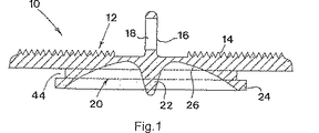
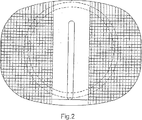
図1および2にみとめられるプロテーゼ板10は、一部品のグレード5のチタンにおいて形成される。そのプロテーゼ板は、粗い鋸歯状の仕上げ14に機械加工される主要な表面12を備える。表面12からの突出しているのは、横断孔18によって貫通される細長いフィン16である。その板10の対向する表面は、そのくぼみの中心における丸い断面の突出する円錐形ペグ22の周りを囲むくぼみ20によって形成される。そのくぼみは、環状リム24によって連結される。そのくぼみの表面26は、凹型に球状に彎曲しており、窒化チタン仕上げを有する。
(Description of Preferred Embodiment)
The
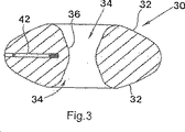
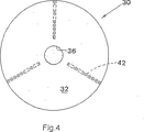
本発明のプロテーゼの第1の実施形態(図5および6において数字28によって一般に示される)は、互いに対向して配置される、一対の同一のプロテーゼ板10を備える。そのプロテーゼ28はまた、図3および4に例示されるコアを備える。そのコアは、この場合、Orthosolとして公知のポリエチレンである一部品の低摩擦プラスチック材料において作製される。そのコアは、一般に、円形のドーナツ形の円錐曲線回転面の形態にあり、凸型に球状に彎曲している、同一の上側および下側の表面32を有する。その上側および下側の表面32は、そのコアの本体を軸方向かつ中心を通過する円形の断面経路の対向する端部を形成する場合において、円錐形開口部34で中心に形成される。
A first embodiment of the prosthesis of the present invention (generally indicated by the
そのコア表面32およびくぼみ表面26は、この場合に18mmである同じ曲率半径を有する。
Its
組み立てられたプロテーゼ28において、その板10は、それらの板の間に位置するコア30と互いに対向して配置される。その板のペグ22は、開口部34に、すなわち、経路36の端部に位置する。混合した長さのペグは、経路36の長さより短く、よってそのペグの内側端部は、図5に示されるように、短い距離38によって互いに離れて間隔が空けられる。各ペグの横断寸法は、ペグの長さに沿った全ての点において、その経路の長さに沿って対応する点において、経路36の直径よりかなり小さい。
In the assembled
協働する球状表面26および32、ならびにペグ22および経路36の相対的な寸法は、中心軸の周りの回転を含めて、かなり大きな範囲の角度を通して、かつ全ての方向または自由な角度において、その板10がそのコアの上をスライドまたは関節結合(articulate)することを可能にする。
The relative dimensions of the cooperating
そのコアに対してその板に関節結合した動きの所定の制限において、その板のリム24は、図6において数字40によって示されるように、互いに接触する。この点を超えるこのプロテーゼ28のさらなる関節結合は、不可能である。関節結合の制限において、そのペグ22はまた、図6においても例示されるように、その経路36の側面と隣接して接触する。
In a predetermined limit of movement articulated to the plate relative to the core, the
その経路36の端部における開口部34は、そのペグ22に対して類似の円錐角度によって規定されることが図6においても示される。その結果、そのペグと開口部の側面との間の接触は、各ペグのほぼ長さ全体にわたって補完的に生じる。あり得る関節結合の範囲全体にわたって、そのペグ22は、経路36に残り、その板10から横方向に分離することを防止する。言い換えると、そのコアは、起こり得る全ての可能な関節結合の間にそのペグによって捕獲したままで保持される。例示的な実施形態において、その板10は、そのリム24が互いに隣接する前に12°の関節結合に制限され、すなわち、12°は、起こり得る最大の関節結合である。
It is also shown in FIG. 6 that the
上記のプロテーゼ28において、そのペグ22は、コア30を直角に通る経路32に位置する。しかし、他の実施形態において、そのペグは、このような開口部が、連続する経路を形成するために互いに実際に連結されることなく、そのコアの対向する表面におけるブラインドくぼみ(blind recess)または開口部に位置するにすぎないことが理解される。
In the
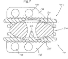
図7は、図5に類似した見え方において本発明の第2の実施形態に従うプロテーゼを例示する。図7において、先の図に例示される構成要素に従う構成要素は、同じ参照番号によって示される。 FIG. 7 illustrates a prosthesis according to a second embodiment of the invention in a view similar to FIG. In FIG. 7, components according to the components illustrated in the previous figure are indicated by the same reference numerals.
図7における下側のプロテーゼ板10は、第1の実施形態のプロテーゼ板に同一である。しかし、上側のプロテーゼ板(10.1と示される)は、中心ペグを有さない。代わりに、その表面26は、連続して、球状に彎曲している。他の全ての点において、板10.1は、プレート10に同一である。
The
組み立てられたプロテーゼ50において、そのコアは、下側のプロテーゼ板10によって保有される単一のペグ22の作用によって捕捉されて保持される。そのコア30は、上記のコアに同一であるが、繰り返すと、コアが、単一のペグ22を受容するためにのみ、その下向きに面する彎曲した表面32において、ブラインドくぼみを有し得ることが理解される。
In the assembled prosthesis 50, its core is captured and held by the action of a
そのプロテーゼ28、50は、損傷した椎間板に代えて、隣接する脊髄の椎骨との間に外科手術により移植される。当業者は、隣接する椎骨が強制的に互いから分離されて、挿入に必要な空間がもたらされることが理解される。その板10、10.1は、それらのフィン16を受容するように、対向する椎骨表面において切断されるスロットに入る、それらのフィン16とともに、椎骨の間の場所に横側から滑り込ませられる。
The
その対向する板の間にコアを挿入した後に、その椎骨を、組み立てられたプロテーゼをその位置に保持するために、一緒に動かせられる。 After inserting the core between the opposing plates, the vertebrae are moved together to hold the assembled prosthesis in place.
板10、10.1の表面12は、その対向する椎骨に対して位置し、時間が経つにつれて、その板の間の接合を安定させ、その椎骨は、鋸歯状の仕上げの上に骨が成長するように目的が達せられる。骨組織の成長はまた、そのフィン16の周りに、そのフィンにおける孔18を通って起こり、目的が達成される接続をさらに増強する。
The
図3および4を参照すると、上記の実施形態において使用されるそのコア30は、チタンピン42を収容する、狭く、角度を付けて空けられたブラインド経路で形成される。そのコア自体は、X線透過性であり、よって、術後X線検査において通常は見えない。そのピン42は、放射線用マーカーとして作用し、そのコア30の位置をこのような検査の間に確認することを可能にする。
With reference to FIGS. 3 and 4, the core 30 used in the above embodiment is formed with a narrow, angled blind path that houses the
環状溝44は板10、10.1に設けられて、椎間板の空間に配置する間に、適切な器具によってプロテーゼの保持および操作が容易にされる。
公知のプロテーゼに比較して、上記のプロテーゼ28、50は、以下のように、多くの利点を有する:
1.そのペグ22は、そのコアが側面から滑り出さないように、コアを捕捉して保持する
2.関節結合の所定の最大の制限において、そのリム24は、さらなる関節結合を防止するように互いに接続する。同時に、そのペグ22は、開口部34の側面と接触し、さらなる関節結合もまた防止する
3.そのコア上の板の許容可能なベアリング領域は、上記の中心ペグ/中心開口部の配置で得られる。このことは、そのコアが、関節結合の制限においてその板上の周辺リムを受容するように、その上側および下側の表面上の周辺チャネルを有する先行技術のプロテーゼと比較して特に有利である。
Compared to known prostheses, the above-mentioned
1. The
実際には、そのプロテーゼ板の不完全な整列が起こり得る。整列が非常に乏しい場合、図5および6の二重ペグ(dual peg)の配置は、そのペグ22が実質的な距離だけ互いから横方向にオフセットされる可能性を生じる。このことは、次いで、適合され得る関節結合の範囲が過度に制限されるという望ましくない結果をもたらし得、その制限を通り越して関節結合しようとすると、誤って整列されたペグによってそのコアに対する損傷を生じ得る。図7の実施形態において、その単一のペグは、そのコアによって中心に受容され得、それによって、この潜在的な問題が避けられる。
In practice, incomplete alignment of the prosthesis plate can occur. If the alignment is very poor, the dual peg arrangement of FIGS. 5 and 6 can cause the
本発明の原理は、腰椎ならびに頸椎のためのプロテーゼ椎間板移植に適用可能である。後者の場合、そのフィン16は、代表的に、省かれる。
The principles of the present invention are applicable to prosthetic disc implantation for lumbar as well as cervical vertebrae. In the latter case, the
本発明は、添付の図面を参照して、例示によってより詳細に記載される。
Claims (11)
第1プロテーゼ板であって、第1椎骨に対して設置可能であり、かつ該プロテーゼ板において、凹型に弯曲したベアリング表面を有する、第1プロテーゼ板;
第2プロテーゼ板であって、第2椎骨に対して設置可能であり、かつ該プロテーゼ板において、ベアリング表面を有する、第2プロテーゼ板;ならびに
該板の間に位置したコアであって、該コアは、該板が該コア上を関節結合した様式でスライドすることを可能にするように該第1板および第2板のベアリング表面と協働する曲率を有する対向した表面を有する、コア
を備え、
該第1板および第2板のそれぞれは、その周囲に環状溝を有し、該溝は、使用中に該プロテーゼを配置するために使用される器具によって該板の取り扱いを容易にするように配置されている、
椎間プロテーゼ。An intervertebral prosthesis for insertion between adjacent vertebrae, the prosthesis being:
A first prosthesis plate, can be disposed relative to the first vertebra, and in said prosthesis plate, having a bearing surface which is curved in a concave-type, the first prosthesis plate;
A second prosthetic plate, positionable with respect to the second vertebra, and having a bearing surface in the prosthetic plate; and a core positioned between the plates , the core comprising : the plate has a front surface facing has a curvature of the first plate and the bearing surface cooperating with the second plate to allow the slide in a manner over the core articulated, comprising a core ,
Each of the first plate and the second plate has an annular groove around it so that the plate can be easily handled by the instrument used to position the prosthesis during use. Arranged,
Intervertebral prosthesis.
Applications Claiming Priority (2)
| Application Number | Priority Date | Filing Date | Title |
|---|---|---|---|
| ZA200207517 | 2002-09-19 | ||
| PCT/IB2003/001529 WO2004026187A1 (en) | 2002-09-19 | 2003-04-24 | Intervertebral prosthesis |
Publications (3)
| Publication Number | Publication Date |
|---|---|
| JP2006500096A JP2006500096A (en) | 2006-01-05 |
| JP2006500096A5 JP2006500096A5 (en) | 2006-06-01 |
| JP4429909B2 true JP4429909B2 (en) | 2010-03-10 |
Family
ID=32031274
Family Applications (1)
| Application Number | Title | Priority Date | Filing Date |
|---|---|---|---|
| JP2004537345A Expired - Fee Related JP4429909B2 (en) | 2002-09-19 | 2003-04-24 | Intervertebral prosthesis |
Country Status (7)
| Country | Link |
|---|---|
| US (14) | US7531001B2 (en) |
| EP (2) | EP1549260B1 (en) |
| JP (1) | JP4429909B2 (en) |
| AT (1) | ATE455518T1 (en) |
| AU (1) | AU2003226586A1 (en) |
| DE (1) | DE60331089D1 (en) |
| WO (1) | WO2004026187A1 (en) |
Families Citing this family (66)
| Publication number | Priority date | Publication date | Assignee | Title |
|---|---|---|---|---|
| WO2004026187A1 (en) | 2002-09-19 | 2004-04-01 | Malan De Villiers | Intervertebral prosthesis |
| EP1587437B1 (en) | 2003-01-31 | 2013-02-27 | Spinalmotion, Inc. | Spinal midline indicator |
| JP4275699B2 (en) | 2003-01-31 | 2009-06-10 | スパイナルモーション, インコーポレイテッド | Intervertebral prosthesis placement instrument |
| US10052211B2 (en) | 2003-05-27 | 2018-08-21 | Simplify Medical Pty Ltd. | Prosthetic disc for intervertebral insertion |
| WO2004105638A2 (en) | 2003-05-27 | 2004-12-09 | Spinalmotion, Inc. | Prosthetic disc for intervertebral insertion |
| US7575599B2 (en) | 2004-07-30 | 2009-08-18 | Spinalmotion, Inc. | Intervertebral prosthetic disc with metallic core |
| US20090076614A1 (en) * | 2007-09-17 | 2009-03-19 | Spinalmotion, Inc. | Intervertebral Prosthetic Disc with Shock Absorption Core |
| US7621956B2 (en) * | 2003-07-31 | 2009-11-24 | Globus Medical, Inc. | Prosthetic spinal disc replacement |
| FR2858546B1 (en) | 2003-08-04 | 2006-04-28 | Spine Next Sa | INTERVERTEBRAL DISC PROSTHESIS |
| EP1532950B1 (en) | 2003-11-18 | 2008-03-26 | Zimmer GmbH | Spinal disc prosthesis |
| US7217291B2 (en) * | 2003-12-08 | 2007-05-15 | St. Francis Medical Technologies, Inc. | System and method for replacing degenerated spinal disks |
| US7585326B2 (en) | 2004-08-06 | 2009-09-08 | Spinalmotion, Inc. | Methods and apparatus for intervertebral disc prosthesis insertion |
| US20060041313A1 (en) * | 2004-08-19 | 2006-02-23 | Sdgi Holdings, Inc. | Intervertebral disc system |
| US7763024B2 (en) * | 2004-09-23 | 2010-07-27 | Spine Solutions, Inc. | Adjustable cutting of cutout in vertebral bone |
| TWI327064B (en) * | 2004-09-23 | 2010-07-11 | Spine Solutions Inc | An intervertebral implant |
| US7780731B2 (en) * | 2004-11-26 | 2010-08-24 | Spine Solutions, Inc. | Intervertebral implant |
| US8083797B2 (en) | 2005-02-04 | 2011-12-27 | Spinalmotion, Inc. | Intervertebral prosthetic disc with shock absorption |
| ES2387392T3 (en) * | 2005-04-15 | 2012-09-21 | Eden Spine Europe Sa | Intervertebral disc prosthesis |
| US8777959B2 (en) | 2005-05-27 | 2014-07-15 | Spinecore, Inc. | Intervertebral disc and insertion methods therefor |
| US20070173942A1 (en) * | 2006-01-26 | 2007-07-26 | Sdgi Holdings, Inc. | Intervertebral prosthetic disc |
| US20070179618A1 (en) * | 2006-01-31 | 2007-08-02 | Sdgi Holdings, Inc. | Intervertebral prosthetic disc |
| JP2009533187A (en) | 2006-04-12 | 2009-09-17 | スパイナルモーション, インコーポレイテッド | Posterior spine apparatus and method |
| WO2008022471A1 (en) * | 2006-08-22 | 2008-02-28 | Synthes Gmbh | Total disc replacement device |
| US8308812B2 (en) | 2006-11-07 | 2012-11-13 | Biomedflex, Llc | Prosthetic joint assembly and joint member therefor |
| US9005306B2 (en) | 2006-11-07 | 2015-04-14 | Biomedflex, Llc | Medical Implants With Compliant Wear-Resistant Surfaces |
| US8512413B2 (en) | 2006-11-07 | 2013-08-20 | Biomedflex, Llc | Prosthetic knee joint |
| US7914580B2 (en) | 2006-11-07 | 2011-03-29 | Biomedflex Llc | Prosthetic ball-and-socket joint |
| US8029574B2 (en) | 2006-11-07 | 2011-10-04 | Biomedflex Llc | Prosthetic knee joint |
| US8070823B2 (en) | 2006-11-07 | 2011-12-06 | Biomedflex Llc | Prosthetic ball-and-socket joint |
| US9005307B2 (en) | 2006-11-07 | 2015-04-14 | Biomedflex, Llc | Prosthetic ball-and-socket joint |
| US7905919B2 (en) * | 2006-11-07 | 2011-03-15 | Biomedflex Llc | Prosthetic joint |
| US20110166671A1 (en) | 2006-11-07 | 2011-07-07 | Kellar Franz W | Prosthetic joint |
| US8715352B2 (en) | 2006-12-14 | 2014-05-06 | Depuy Spine, Inc. | Buckling disc replacement |
| US20090043391A1 (en) | 2007-08-09 | 2009-02-12 | Spinalmotion, Inc. | Customized Intervertebral Prosthetic Disc with Shock Absorption |
| WO2009055478A1 (en) | 2007-10-22 | 2009-04-30 | Spinalmotion, Inc. | Vertebral body replacement and method for spanning a space formed upon removal of a vertebral body |
| ATE470412T1 (en) * | 2007-11-07 | 2010-06-15 | Gs Dev Ab | ARTIFICIAL JOINT |
| US8764833B2 (en) | 2008-03-11 | 2014-07-01 | Spinalmotion, Inc. | Artificial intervertebral disc with lower height |
| US9034038B2 (en) | 2008-04-11 | 2015-05-19 | Spinalmotion, Inc. | Motion limiting insert for an artificial intervertebral disc |
| EP2278941A1 (en) | 2008-05-05 | 2011-02-02 | Spinalmotion Inc. | Polyaryletherketone artificial intervertebral disc |
| US9220603B2 (en) | 2008-07-02 | 2015-12-29 | Simplify Medical, Inc. | Limited motion prosthetic intervertebral disc |
| WO2010009151A2 (en) | 2008-07-17 | 2010-01-21 | Spinalmotion, Inc. | Artificial intervertebral disc placement system |
| EP2299941A1 (en) | 2008-07-18 | 2011-03-30 | Spinalmotion Inc. | Posterior prosthetic intervertebral disc |
| US8147554B2 (en) * | 2008-10-13 | 2012-04-03 | Globus Medical, Inc. | Intervertebral spacer |
| US8545566B2 (en) | 2008-10-13 | 2013-10-01 | Globus Medical, Inc. | Articulating spacer |
| KR101043865B1 (en) * | 2009-06-30 | 2011-06-22 | 주식회사 하이닉스반도체 | Fuse structure for high integrated semiconductor device |
| FR2948558A1 (en) * | 2009-07-31 | 2011-02-04 | Euros Sa | INTERVERTEBRAL DISC PROSTHESIS |
| US8403988B2 (en) | 2009-09-11 | 2013-03-26 | Depuy Spine, Inc. | Minimally invasive intervertebral staple distraction devices |
| US9615933B2 (en) | 2009-09-15 | 2017-04-11 | DePuy Synthes Products, Inc. | Expandable ring intervertebral fusion device |
| US20120101579A1 (en) * | 2010-04-27 | 2012-04-26 | Spinalmotion, Inc. | Prosthetic intervertebral disc with movable core |
| US9358122B2 (en) | 2011-01-07 | 2016-06-07 | K2M, Inc. | Interbody spacer |
| US8998991B2 (en) * | 2011-02-23 | 2015-04-07 | Globus Medical, Inc. | Six degree spine stabilization devices and methods |
| US8480743B2 (en) * | 2011-03-25 | 2013-07-09 | Vicente Vanaclocha Vanaclocha | Universal disc prosthesis |
| US8277505B1 (en) | 2011-06-10 | 2012-10-02 | Doty Keith L | Devices for providing up to six-degrees of motion having kinematically-linked components and methods of use |
| US8808384B2 (en) | 2011-10-13 | 2014-08-19 | Simplify Medical, Inc. | Anatomy accomodating prosthetic intervertebral disc with lower height |
| US8287598B1 (en) | 2011-12-05 | 2012-10-16 | TrueMotion Spine, Inc. | True spinal motion preserving, shock absorbing, intervertebral spinal disc prosthesis |
| US20130261746A1 (en) * | 2012-03-28 | 2013-10-03 | Linares Medical Devices, Llc | Implantable inter-vertebral disk having upper and lower layers of a metal exhibiting bone fusing characteristics and which sandwich therebetween a soft plastic cushioning disc for providing dynamic properties mimicking that of a natural inter-vertebral disc |
| US9655735B2 (en) * | 2013-03-15 | 2017-05-23 | Atlas Spine, Inc. | Spinal disc prosthesis |
| EP3291768B1 (en) | 2015-04-24 | 2019-11-27 | Biomet Manufacturing, LLC | Patient-specific augmented glenoid systems |
| US10426628B2 (en) | 2017-12-14 | 2019-10-01 | Simplify Medical Pty Ltd | Intervertebral prosthesis |
| US11819424B2 (en) | 2018-09-24 | 2023-11-21 | Simplify Medical Pty Ltd | Robot assisted intervertebral disc prosthesis selection and implantation system |
| US11219536B2 (en) | 2019-05-01 | 2022-01-11 | Simplify Medical Pty Ltd | Intervertebral prosethetic disc placement and removal systems |
| US11452618B2 (en) | 2019-09-23 | 2022-09-27 | Dimicron, Inc | Spinal artificial disc removal tool |
| EP4034002A4 (en) | 2019-09-24 | 2023-11-01 | Simplify Medical Pty Limited | Surgical cutter instrument with trial |
| US11071632B2 (en) | 2020-04-04 | 2021-07-27 | Young Hoon Oh | Intervertebral implant device |
| US11642226B2 (en) * | 2020-05-01 | 2023-05-09 | Ensemble Orthopedics, Inc. | Implantable interpositional orthopedic pain management |
| WO2023091346A1 (en) * | 2021-11-17 | 2023-05-25 | Acuity Surgical Devices Llc | Method and apparatus for reducing human vertebral body subsidence using variable surface area interbody cages correlated to localized bone density measurements |
Family Cites Families (185)
| Publication number | Priority date | Publication date | Assignee | Title |
|---|---|---|---|---|
| US1016611A (en) | 1911-06-09 | 1912-02-06 | Henry J Chilton | Bottle filling and capping machine. |
| US3486505A (en) | 1967-05-22 | 1969-12-30 | Gordon M Morrison | Orthopedic surgical instrument |
| CH640131A5 (en) | 1979-10-03 | 1983-12-30 | Sulzer Ag | Complete intervertebral prosthesis |
| US4566466A (en) | 1984-04-16 | 1986-01-28 | Ripple Dale B | Surgical instrument |
| ATE44871T1 (en) * | 1984-09-04 | 1989-08-15 | Univ Berlin Humboldt | DISC PROSTHESIS. |
| US4834757A (en) | 1987-01-22 | 1989-05-30 | Brantigan John W | Prosthetic implant |
| CA1283501C (en) | 1987-02-12 | 1991-04-30 | Thomas P. Hedman | Artificial spinal disc |
| US4863477A (en) | 1987-05-12 | 1989-09-05 | Monson Gary L | Synthetic intervertebral disc prosthesis |
| JPH01136655A (en) | 1987-11-24 | 1989-05-29 | Asahi Optical Co Ltd | Movable type pyramid spacer |
| US4874389A (en) | 1987-12-07 | 1989-10-17 | Downey Ernest L | Replacement disc |
| US5195526A (en) | 1988-03-11 | 1993-03-23 | Michelson Gary K | Spinal marker needle |
| DE3809793A1 (en) | 1988-03-23 | 1989-10-05 | Link Waldemar Gmbh Co | SURGICAL INSTRUMENT SET |
| US5593409A (en) | 1988-06-13 | 1997-01-14 | Sofamor Danek Group, Inc. | Interbody spinal fusion implants |
| AU7139994A (en) | 1988-06-13 | 1995-01-03 | Karlin Technology, Inc. | Apparatus and method of inserting spinal implants |
| US5484437A (en) | 1988-06-13 | 1996-01-16 | Michelson; Gary K. | Apparatus and method of inserting spinal implants |
| US5609635A (en) | 1988-06-28 | 1997-03-11 | Michelson; Gary K. | Lordotic interbody spinal fusion implants |
| CA1318469C (en) | 1989-02-15 | 1993-06-01 | Acromed Corporation | Artificial disc |
| DE8912648U1 (en) * | 1989-10-23 | 1990-11-22 | Mecron Medizinische Produkte Gmbh, 1000 Berlin, De | |
| US5057108A (en) | 1990-01-12 | 1991-10-15 | Zimmer, Inc. | Method of surface finishing orthopedic implant devices |
| FR2659226B1 (en) | 1990-03-07 | 1992-05-29 | Jbs Sa | PROSTHESIS FOR INTERVERTEBRAL DISCS AND ITS IMPLEMENTATION INSTRUMENTS. |
| GB9110778D0 (en) | 1991-05-18 | 1991-07-10 | Middleton Jeffrey K | Apparatus for use in surgery |
| GB9125798D0 (en) | 1991-12-04 | 1992-02-05 | Customflex Limited | Improvements in or relating to spinal vertebrae implants |
| US5258031A (en) | 1992-01-06 | 1993-11-02 | Danek Medical | Intervertebral disk arthroplasty |
| EP0555033B1 (en) | 1992-02-07 | 1999-05-26 | Smith & Nephew, Inc. | Surface hardened biocompatible metallic medical implants |
| US5282861A (en) | 1992-03-11 | 1994-02-01 | Ultramet | Open cell tantalum structures for cancellous bone implants and cell and tissue receptors |
| DE4208115A1 (en) | 1992-03-13 | 1993-09-16 | Link Waldemar Gmbh Co | DISC ENDOPROTHESIS |
| DE4208116C2 (en) | 1992-03-13 | 1995-08-03 | Link Waldemar Gmbh Co | Intervertebral disc prosthesis |
| ATE141149T1 (en) | 1992-04-21 | 1996-08-15 | Sulzer Medizinaltechnik Ag | ARTIFICIAL DISC BODY |
| US5282661A (en) * | 1992-06-30 | 1994-02-01 | Steyr-Daimler-Puch Ag | Collapsible driver's cab for a truck |
| DE4233978C1 (en) | 1992-10-08 | 1994-04-21 | Leibinger Gmbh | Body marking device for medical examinations |
| US5676701A (en) | 1993-01-14 | 1997-10-14 | Smith & Nephew, Inc. | Low wear artificial spinal disc |
| DE69428143T2 (en) | 1993-02-09 | 2002-05-29 | Depuy Acromed Inc | disc |
| JP3695755B2 (en) | 1993-02-10 | 2005-09-14 | ジンマー スパイン、インク. | Spinal fusion surgery tool kit |
| DK0703757T3 (en) | 1993-06-10 | 2003-12-29 | Karlin Technology Inc | Spinal implant insertion device |
| FR2707480B1 (en) | 1993-06-28 | 1995-10-20 | Bisserie Michel | Intervertebral disc prosthesis. |
| US5899911A (en) | 1993-08-25 | 1999-05-04 | Inlet Medical, Inc. | Method of using needle-point suture passer to retract and reinforce ligaments |
| US5462575A (en) | 1993-12-23 | 1995-10-31 | Crs Holding, Inc. | Co-Cr-Mo powder metallurgy articles and process for their manufacture |
| US5674296A (en) | 1994-11-14 | 1997-10-07 | Spinal Dynamics Corporation | Human spinal disc prosthesis |
| FR2728159B1 (en) | 1994-12-16 | 1997-06-27 | Tornier Sa | ELASTIC DISC PROSTHESIS |
| US5683391A (en) | 1995-06-07 | 1997-11-04 | Danek Medical, Inc. | Anterior spinal instrumentation and method for implantation and revision |
| US5709683A (en) * | 1995-12-19 | 1998-01-20 | Spine-Tech, Inc. | Interbody bone implant having conjoining stabilization features for bony fusion |
| US6159214A (en) | 1996-07-31 | 2000-12-12 | Michelson; Gary K. | Milling instrumentation and method for preparing a space between adjacent vertebral bodies |
| US5728159A (en) | 1997-01-02 | 1998-03-17 | Musculoskeletal Transplant Foundation | Serrated bone graft |
| JP3955883B2 (en) | 1997-04-15 | 2007-08-08 | ジンテーズ ゲゼルシャフト ミト ベシュレンクテル ハフツング | Telescopic vertebral body prosthesis |
| US6022376A (en) | 1997-06-06 | 2000-02-08 | Raymedica, Inc. | Percutaneous prosthetic spinal disc nucleus and method of manufacture |
| US6146421A (en) | 1997-08-04 | 2000-11-14 | Gordon, Maya, Roberts And Thomas, Number 1, Llc | Multiple axis intervertebral prosthesis |
| US20010016773A1 (en) | 1998-10-15 | 2001-08-23 | Hassan Serhan | Spinal disc |
| US5824094A (en) | 1997-10-17 | 1998-10-20 | Acromed Corporation | Spinal disc |
| ES2297898T3 (en) | 1997-10-27 | 2008-05-01 | St. Francis Medical Technologies, Inc. | VERTEBRAL DISTRACTION IMPLANT. |
| US6139579A (en) | 1997-10-31 | 2000-10-31 | Depuy Motech Acromed, Inc. | Spinal disc |
| US5888226A (en) | 1997-11-12 | 1999-03-30 | Rogozinski; Chaim | Intervertebral prosthetic disc |
| US6162252A (en) | 1997-12-12 | 2000-12-19 | Depuy Acromed, Inc. | Artificial spinal disc |
| US6143033A (en) | 1998-01-30 | 2000-11-07 | Synthes (Usa) | Allogenic intervertebral implant |
| US6986788B2 (en) * | 1998-01-30 | 2006-01-17 | Synthes (U.S.A.) | Intervertebral allograft spacer |
| US5989291A (en) | 1998-02-26 | 1999-11-23 | Third Millennium Engineering, Llc | Intervertebral spacer device |
| US6019792A (en) | 1998-04-23 | 2000-02-01 | Cauthen Research Group, Inc. | Articulating spinal implant |
| US6132465A (en) | 1998-06-04 | 2000-10-17 | Raymedica, Inc. | Tapered prosthetic spinal disc nucleus |
| EP1681021A3 (en) | 1998-06-09 | 2009-04-15 | Warsaw Orthopedic, Inc. | Abrading element for preparing a space between adjacent vertebral bodies |
| US6083228A (en) | 1998-06-09 | 2000-07-04 | Michelson; Gary K. | Device and method for preparing a space between adjacent vertebrae to receive an insert |
| US6136031A (en) | 1998-06-17 | 2000-10-24 | Surgical Dynamics, Inc. | Artificial intervertebral disc |
| US5928284A (en) | 1998-07-09 | 1999-07-27 | Mehdizadeh; Hamid M. | Disc replacement prosthesis |
| WO2000004851A1 (en) * | 1998-07-22 | 2000-02-03 | Spinal Dynamics Corporation | Threaded cylindrical multidiscoid single or multiple array disc prosthesis |
| EP1100417B1 (en) | 1998-08-03 | 2004-04-07 | SYNTHES AG Chur | Intervertebral allograft spacer |
| JP2002524141A (en) | 1998-09-04 | 2002-08-06 | スパイナル ダイナミックス コーポレイション | Peanut spectacle-shaped thoracolumbar disc prosthesis containing multiple discs |
| DE69940641D1 (en) | 1998-10-02 | 2009-05-07 | Synthes Gmbh | Ffe |
| US6039763A (en) | 1998-10-27 | 2000-03-21 | Disc Replacement Technologies, Inc. | Articulating spinal disc prosthesis |
| FR2787017B1 (en) * | 1998-12-11 | 2001-04-27 | Dimso Sa | INTERVERTEBRAL DISC PROSTHESIS WITH IMPROVED MECHANICAL BEHAVIOR |
| FR2787016B1 (en) | 1998-12-11 | 2001-03-02 | Dimso Sa | INTERVERTEBRAL DISK PROSTHESIS |
| FR2787015B1 (en) | 1998-12-11 | 2001-04-27 | Dimso Sa | INTERVERTEBRAL DISC PROSTHESIS WITH COMPRESSIBLE BODY |
| FR2787014B1 (en) | 1998-12-11 | 2001-03-02 | Dimso Sa | INTERVERTEBRAL DISC PROSTHESIS WITH REDUCED FRICTION |
| FR2787018B1 (en) | 1998-12-11 | 2001-03-02 | Dimso Sa | INTERVERTEBRAL DISC PROSTHESIS WITH LIQUID ENCLOSURE |
| US6322567B1 (en) | 1998-12-14 | 2001-11-27 | Integrated Surgical Systems, Inc. | Bone motion tracking system |
| US6547823B2 (en) * | 1999-01-22 | 2003-04-15 | Osteotech, Inc. | Intervertebral implant |
| ATE464847T1 (en) | 1999-01-25 | 2010-05-15 | Warsaw Orthopedic Inc | INSTRUMENT FOR CREATION OF AN INTERVERBEL SPACE FOR ACCOMMODATION OF AN IMPLANT |
| DE29901611U1 (en) | 1999-01-30 | 1999-04-22 | Aesculap Ag & Co Kg | Surgical instrument for inserting intervertebral implants |
| US6743234B2 (en) | 1999-02-04 | 2004-06-01 | Sdgi Holdings, Inc. | Methods and instrumentation for vertebral interbody fusion |
| US6368350B1 (en) * | 1999-03-11 | 2002-04-09 | Sulzer Spine-Tech Inc. | Intervertebral disc prosthesis and method |
| EP1057462B1 (en) | 1999-05-21 | 2003-04-02 | Waldemar Link (GmbH & Co.) | Intervertebral endoprosthesis with a toothed connection plate |
| US6520996B1 (en) | 1999-06-04 | 2003-02-18 | Depuy Acromed, Incorporated | Orthopedic implant |
| JP4192262B2 (en) | 1999-07-02 | 2008-12-10 | スパイン ソリューションズ インコーポレイテッド | Intervertebral implant |
| GB9915465D0 (en) * | 1999-07-02 | 1999-09-01 | Lenzie Robert S | Identified preferred indexes for databases |
| US7201776B2 (en) | 1999-10-08 | 2007-04-10 | Ferree Bret A | Artificial intervertebral disc replacements with endplates |
| EP1207821B1 (en) | 1999-08-27 | 2004-08-04 | SYNTHES AG Chur | Intervertebral implant |
| US6264695B1 (en) | 1999-09-30 | 2001-07-24 | Replication Medical, Inc. | Spinal nucleus implant |
| US7201774B2 (en) | 1999-10-08 | 2007-04-10 | Ferree Bret A | Artificial intervertebral disc replacements incorporating reinforced wall sections |
| FR2799639B1 (en) | 1999-10-18 | 2002-07-19 | Dimso Sa | TOOTHED FACED INTERVERTEBRAL DISC PROSTHESIS |
| US6520967B1 (en) | 1999-10-20 | 2003-02-18 | Cauthen Research Group, Inc. | Spinal implant insertion instrument for spinal interbody prostheses |
| WO2001028469A2 (en) | 1999-10-21 | 2001-04-26 | Sdgi Holdings, Inc. | Devices and techniques for a posterior lateral disc space approach |
| US6592624B1 (en) | 1999-11-24 | 2003-07-15 | Depuy Acromed, Inc. | Prosthetic implant element |
| US6827740B1 (en) | 1999-12-08 | 2004-12-07 | Gary K. Michelson | Spinal implant surface configuration |
| FR2803741B1 (en) * | 2000-01-13 | 2003-04-11 | Jean Claude Bouvet | INTERSOMATIC CAGE |
| FR2805733B1 (en) | 2000-03-03 | 2002-06-07 | Scient X | DISC PROSTHESIS FOR CERVICAL VERTEBRUS |
| FR2805985B1 (en) | 2000-03-10 | 2003-02-07 | Eurosurgical | INTERVERTEBRAL DISK PROSTHESIS |
| AR027685A1 (en) | 2000-03-22 | 2003-04-09 | Synthes Ag | METHOD AND METHOD FOR CARRYING OUT |
| EP1142544B1 (en) | 2000-04-04 | 2008-03-26 | Link Spine Group, Inc. | Intervertebral implant |
| US6478800B1 (en) | 2000-05-08 | 2002-11-12 | Depuy Acromed, Inc. | Medical installation tool |
| US6533817B1 (en) | 2000-06-05 | 2003-03-18 | Raymedica, Inc. | Packaged, partially hydrated prosthetic disc nucleus |
| US6852126B2 (en) * | 2000-07-17 | 2005-02-08 | Nuvasive, Inc. | Stackable interlocking intervertebral support system |
| EP1363565A2 (en) | 2000-08-08 | 2003-11-26 | SDGI Holdings, Inc. | Implantable joint prosthesis |
| US20020035400A1 (en) * | 2000-08-08 | 2002-03-21 | Vincent Bryan | Implantable joint prosthesis |
| US6666866B2 (en) | 2000-11-07 | 2003-12-23 | Osteotech, Inc. | Spinal intervertebral implant insertion tool |
| DE10065232C2 (en) | 2000-12-27 | 2002-11-14 | Ulrich Gmbh & Co Kg | Implant for insertion between the vertebral body and surgical instrument for handling the implant |
| DE60224850T2 (en) | 2001-02-04 | 2009-01-22 | Warsaw Orthopedic, Inc., Warsaw | Instrumentation for introducing and positioning an expandable intervertebral fusion implant |
| US6986772B2 (en) | 2001-03-01 | 2006-01-17 | Michelson Gary K | Dynamic lordotic guard with movable extensions for creating an implantation space posteriorly in the lumbar spine |
| US6673113B2 (en) | 2001-10-18 | 2004-01-06 | Spinecore, Inc. | Intervertebral spacer device having arch shaped spring elements |
| US7235081B2 (en) | 2001-07-16 | 2007-06-26 | Spinecore, Inc. | Wedge plate inserter/impactor and related methods for use in implanting an artificial intervertebral disc |
| US6607559B2 (en) | 2001-07-16 | 2003-08-19 | Spine Care, Inc. | Trial intervertebral distraction spacers |
| US7169182B2 (en) * | 2001-07-16 | 2007-01-30 | Spinecore, Inc. | Implanting an artificial intervertebral disc |
| US6896680B2 (en) | 2001-03-01 | 2005-05-24 | Gary K. Michelson | Arcuate dynamic lordotic guard with movable extensions for creating an implantation space posteriorly in the lumbar spine |
| EP1250898A1 (en) | 2001-04-05 | 2002-10-23 | Waldemar Link (GmbH & Co.) | Intervertebral disc prosthesis system |
| US6719794B2 (en) * | 2001-05-03 | 2004-04-13 | Synthes (U.S.A.) | Intervertebral implant for transforaminal posterior lumbar interbody fusion procedure |
| FR2824261B1 (en) * | 2001-05-04 | 2004-05-28 | Ldr Medical | INTERVERTEBRAL DISC PROSTHESIS AND IMPLEMENTATION METHOD AND TOOLS |
| US6607558B2 (en) | 2001-07-03 | 2003-08-19 | Axiomed Spine Corporation | Artificial disc |
| US7160327B2 (en) | 2001-07-16 | 2007-01-09 | Spinecore, Inc. | Axially compressible artificial intervertebral disc having limited rotation using a captured ball and socket joint with a solid ball and compression locking post |
| US7153310B2 (en) | 2001-07-16 | 2006-12-26 | Spinecore, Inc. | Vertebral bone distraction instruments |
| US6471725B1 (en) | 2001-07-16 | 2002-10-29 | Third Millenium Engineering, Llc | Porous intervertebral distraction spacers |
| US6562047B2 (en) | 2001-07-16 | 2003-05-13 | Spine Core, Inc. | Vertebral bone distraction instruments |
| US6447548B1 (en) * | 2001-07-16 | 2002-09-10 | Third Millennium Engineering, Llc | Method of surgically treating scoliosis |
| US6436102B1 (en) | 2001-07-16 | 2002-08-20 | Third Millennium Engineering, Llc | Method of distracting vertebral bones |
| US7182784B2 (en) | 2001-07-18 | 2007-02-27 | Smith & Nephew, Inc. | Prosthetic devices employing oxidized zirconium and other abrasion resistant surfaces contacting surfaces of cross-linked polyethylene |
| ATE398431T1 (en) | 2001-08-24 | 2008-07-15 | Zimmer Gmbh | ARTIFICIAL DISC |
| US6652533B2 (en) | 2001-09-20 | 2003-11-25 | Depuy Acromed, Inc. | Medical inserter tool with slaphammer |
| US6648917B2 (en) | 2001-10-17 | 2003-11-18 | Medicinelodge, Inc. | Adjustable bone fusion implant and method |
| EP1306064A1 (en) | 2001-10-29 | 2003-05-02 | Waldemar Link (GmbH & Co.) | Instrument for inserting an intervertebral prosthesis |
| US6709439B2 (en) | 2001-10-30 | 2004-03-23 | Depuy Spine, Inc. | Slaphammer tool |
| FR2831796B1 (en) | 2001-11-06 | 2003-12-26 | Ldr Medical | BONE ANCHORING DEVICE FOR PROSTHESIS |
| US7025787B2 (en) | 2001-11-26 | 2006-04-11 | Sdgi Holdings, Inc. | Implantable joint prosthesis and associated instrumentation |
| US6740118B2 (en) * | 2002-01-09 | 2004-05-25 | Sdgi Holdings, Inc. | Intervertebral prosthetic joint |
| EP1344507A1 (en) | 2002-03-12 | 2003-09-17 | Waldemar Link (GmbH & Co.) | Intervertebral prosthesis for the cervical spine |
| DE50213818D1 (en) | 2002-03-12 | 2009-10-15 | Cervitech Inc | Intrumentarium for the insertion of an intervertebral prosthesis |
| DE50210270D1 (en) | 2002-03-12 | 2007-07-19 | Cervitech Inc | Intervertebral prosthesis, especially for the cervical spine |
| EP1344506A1 (en) | 2002-03-12 | 2003-09-17 | Waldemar Link (GmbH & Co.) | Intervertebral prosthesis for the cervical spine |
| US6726720B2 (en) | 2002-03-27 | 2004-04-27 | Depuy Spine, Inc. | Modular disc prosthesis |
| CA2375070C (en) | 2002-03-28 | 2004-03-02 | 4254563 Manitoba Ltd. | Patch plug |
| US20030195631A1 (en) | 2002-04-12 | 2003-10-16 | Ferree Bret A. | Shape-memory spacers for artificial disc replacements |
| US6706068B2 (en) | 2002-04-23 | 2004-03-16 | Bret A. Ferree | Artificial disc replacements with natural kinematics |
| US20040030391A1 (en) * | 2002-04-24 | 2004-02-12 | Bret Ferree | Artificial intervertebral disc spacers |
| US7179294B2 (en) * | 2002-04-25 | 2007-02-20 | Warsaw Orthopedic, Inc. | Articular disc prosthesis and method for implanting the same |
| US6689132B2 (en) | 2002-05-15 | 2004-02-10 | Spineco, Inc. | Spinal implant insertion tool |
| US6770095B2 (en) | 2002-06-18 | 2004-08-03 | Depuy Acroned, Inc. | Intervertebral disc |
| US6793678B2 (en) | 2002-06-27 | 2004-09-21 | Depuy Acromed, Inc. | Prosthetic intervertebral motion disc having dampening |
| US6929166B2 (en) * | 2002-06-28 | 2005-08-16 | Akira Furutsu | Tag attaching device |
| US6723097B2 (en) | 2002-07-23 | 2004-04-20 | Depuy Spine, Inc. | Surgical trial implant |
| US7901407B2 (en) | 2002-08-02 | 2011-03-08 | Boston Scientific Scimed, Inc. | Media delivery device for bone structures |
| WO2004026187A1 (en) * | 2002-09-19 | 2004-04-01 | Malan De Villiers | Intervertebral prosthesis |
| CA2499183A1 (en) | 2002-09-20 | 2004-04-01 | Sdgi Holdings, Inc. | Instrument and method for extraction of an implant |
| DE10247762A1 (en) | 2002-10-14 | 2004-04-22 | Waldemar Link (Gmbh & Co.) | Intervertebral prosthesis |
| US6966929B2 (en) * | 2002-10-29 | 2005-11-22 | St. Francis Medical Technologies, Inc. | Artificial vertebral disk replacement implant with a spacer |
| US7497859B2 (en) * | 2002-10-29 | 2009-03-03 | Kyphon Sarl | Tools for implanting an artificial vertebral disk |
| FR2846550B1 (en) | 2002-11-05 | 2006-01-13 | Ldr Medical | INTERVERTEBRAL DISC PROSTHESIS |
| EP1417940A1 (en) | 2002-11-08 | 2004-05-12 | Waldemar Link (GmbH & Co.) | Vertebral prosthesis |
| US6963071B2 (en) | 2002-11-25 | 2005-11-08 | Intel Corporation | Debris mitigation device |
| AU2003297195A1 (en) | 2002-12-17 | 2004-07-22 | Amedica Corporation | Total disc implant |
| EP1587437B1 (en) * | 2003-01-31 | 2013-02-27 | Spinalmotion, Inc. | Spinal midline indicator |
| JP4275699B2 (en) * | 2003-01-31 | 2009-06-10 | スパイナルモーション, インコーポレイテッド | Intervertebral prosthesis placement instrument |
| US6908484B2 (en) * | 2003-03-06 | 2005-06-21 | Spinecore, Inc. | Cervical disc replacement |
| US7303582B2 (en) | 2003-03-21 | 2007-12-04 | Advanced Medical Optics, Inc. | Foldable angle-fixated intraocular lens |
| US7172784B2 (en) * | 2003-03-28 | 2007-02-06 | Council Of Scientific & Industrial Research | Emulsifier composition for cakes and a method of making improved quality cakes thereof |
| US6969405B2 (en) | 2003-04-23 | 2005-11-29 | Loubert Suddaby | Inflatable intervertebral disc replacement prosthesis |
| US7407513B2 (en) * | 2003-05-02 | 2008-08-05 | Smart Disc, Inc. | Artificial spinal disk |
| US7575599B2 (en) | 2004-07-30 | 2009-08-18 | Spinalmotion, Inc. | Intervertebral prosthetic disc with metallic core |
| WO2004105638A2 (en) | 2003-05-27 | 2004-12-09 | Spinalmotion, Inc. | Prosthetic disc for intervertebral insertion |
| US7270679B2 (en) | 2003-05-30 | 2007-09-18 | Warsaw Orthopedic, Inc. | Implants based on engineered metal matrix composite materials having enhanced imaging and wear resistance |
| US7621956B2 (en) * | 2003-07-31 | 2009-11-24 | Globus Medical, Inc. | Prosthetic spinal disc replacement |
| EP1532950B1 (en) | 2003-11-18 | 2008-03-26 | Zimmer GmbH | Spinal disc prosthesis |
| WO2005053580A1 (en) | 2003-11-28 | 2005-06-16 | Richard Mervyn Walker | An intervertebral prosthesis |
| FR2864763B1 (en) * | 2004-01-07 | 2006-11-24 | Scient X | PROSTHETIC DISCALE FOR VERTEBRATES |
| FR2865629B1 (en) * | 2004-02-04 | 2007-01-26 | Ldr Medical | INTERVERTEBRAL DISC PROSTHESIS |
| US7214244B2 (en) * | 2004-02-19 | 2007-05-08 | Spinecore, Inc. | Artificial intervertebral disc having an articulating joint |
| EP2641571B1 (en) * | 2004-06-30 | 2016-04-13 | Synergy Disc Replacement Inc. | Artificial spinal disc |
| US8021428B2 (en) * | 2004-06-30 | 2011-09-20 | Depuy Spine, Inc. | Ceramic disc prosthesis |
| US7585326B2 (en) | 2004-08-06 | 2009-09-08 | Spinalmotion, Inc. | Methods and apparatus for intervertebral disc prosthesis insertion |
| US20060041313A1 (en) * | 2004-08-19 | 2006-02-23 | Sdgi Holdings, Inc. | Intervertebral disc system |
| US7575600B2 (en) * | 2004-09-29 | 2009-08-18 | Kyphon Sarl | Artificial vertebral disk replacement implant with translating articulation contact surface and method |
| US8083797B2 (en) * | 2005-02-04 | 2011-12-27 | Spinalmotion, Inc. | Intervertebral prosthetic disc with shock absorption |
| JP2009533187A (en) | 2006-04-12 | 2009-09-17 | スパイナルモーション, インコーポレイテッド | Posterior spine apparatus and method |
| US20080051901A1 (en) * | 2006-07-28 | 2008-02-28 | Spinalmotion, Inc. | Spinal Prosthesis with Multiple Pillar Anchors |
| US20080051900A1 (en) * | 2006-07-28 | 2008-02-28 | Spinalmotion, Inc. | Spinal Prosthesis with Offset Anchors |
| US20090043391A1 (en) * | 2007-08-09 | 2009-02-12 | Spinalmotion, Inc. | Customized Intervertebral Prosthetic Disc with Shock Absorption |
| WO2009055478A1 (en) * | 2007-10-22 | 2009-04-30 | Spinalmotion, Inc. | Vertebral body replacement and method for spanning a space formed upon removal of a vertebral body |
| US9034038B2 (en) * | 2008-04-11 | 2015-05-19 | Spinalmotion, Inc. | Motion limiting insert for an artificial intervertebral disc |
| EP2278941A1 (en) | 2008-05-05 | 2011-02-02 | Spinalmotion Inc. | Polyaryletherketone artificial intervertebral disc |
| US9220603B2 (en) * | 2008-07-02 | 2015-12-29 | Simplify Medical, Inc. | Limited motion prosthetic intervertebral disc |
| WO2010009151A2 (en) * | 2008-07-17 | 2010-01-21 | Spinalmotion, Inc. | Artificial intervertebral disc placement system |
| EP2299941A1 (en) * | 2008-07-18 | 2011-03-30 | Spinalmotion Inc. | Posterior prosthetic intervertebral disc |
-
2003
- 2003-04-24 WO PCT/IB2003/001529 patent/WO2004026187A1/en active Application Filing
- 2003-04-24 EP EP03797389A patent/EP1549260B1/en not_active Expired - Lifetime
- 2003-04-24 AU AU2003226586A patent/AU2003226586A1/en not_active Abandoned
- 2003-04-24 DE DE60331089T patent/DE60331089D1/en not_active Expired - Lifetime
- 2003-04-24 JP JP2004537345A patent/JP4429909B2/en not_active Expired - Fee Related
- 2003-04-24 EP EP08163926A patent/EP2002805A3/en not_active Withdrawn
- 2003-04-24 AT AT03797389T patent/ATE455518T1/en not_active IP Right Cessation
-
2005
- 2005-03-18 US US11/084,224 patent/US7531001B2/en not_active Expired - Lifetime
-
2006
- 2006-08-30 US US11/468,618 patent/US7731754B2/en not_active Expired - Lifetime
- 2006-08-30 US US11/468,601 patent/US20060293754A1/en not_active Abandoned
-
2007
- 2007-10-31 US US11/982,420 patent/US20080294259A1/en not_active Abandoned
- 2007-10-31 US US11/982,431 patent/US20080228277A1/en not_active Abandoned
-
2008
- 2008-05-30 US US12/129,868 patent/US8262732B2/en not_active Expired - Lifetime
-
2010
- 2010-03-25 US US12/731,993 patent/US20100179419A1/en not_active Abandoned
-
2016
- 2016-10-03 US US15/284,344 patent/US9839525B2/en not_active Expired - Lifetime
-
2017
- 2017-03-14 US US15/458,913 patent/US10166113B2/en not_active Expired - Lifetime
- 2017-11-14 US US15/812,209 patent/US10517738B2/en not_active Expired - Lifetime
-
2018
- 2018-08-22 US US16/108,773 patent/US11285013B2/en not_active Expired - Lifetime
- 2018-11-13 US US16/189,802 patent/US10413420B2/en not_active Expired - Lifetime
-
2019
- 2019-08-05 US US16/532,176 patent/US11344427B2/en not_active Expired - Lifetime
-
2021
- 2021-12-30 US US17/565,858 patent/US11707360B2/en not_active Expired - Lifetime
Also Published As
Similar Documents
| Publication | Publication Date | Title |
|---|---|---|
| JP4429909B2 (en) | Intervertebral prosthesis | |
| US11376130B2 (en) | Intervertebral prosthetic disc | |
| US10219911B2 (en) | Prosthetic disc for intervertebral insertion |
Legal Events
| Date | Code | Title | Description |
|---|---|---|---|
| A521 | Request for written amendment filed |
Free format text: JAPANESE INTERMEDIATE CODE: A523 Effective date: 20060405 |
|
| A621 | Written request for application examination |
Free format text: JAPANESE INTERMEDIATE CODE: A621 Effective date: 20060405 |
|
| A131 | Notification of reasons for refusal |
Free format text: JAPANESE INTERMEDIATE CODE: A131 Effective date: 20081211 |
|
| A521 | Request for written amendment filed |
Free format text: JAPANESE INTERMEDIATE CODE: A523 Effective date: 20090304 |
|
| A131 | Notification of reasons for refusal |
Free format text: JAPANESE INTERMEDIATE CODE: A131 Effective date: 20090428 |
|
| TRDD | Decision of grant or rejection written | ||
| A01 | Written decision to grant a patent or to grant a registration (utility model) |
Free format text: JAPANESE INTERMEDIATE CODE: A01 Effective date: 20091127 |
|
| A01 | Written decision to grant a patent or to grant a registration (utility model) |
Free format text: JAPANESE INTERMEDIATE CODE: A01 |
|
| A61 | First payment of annual fees (during grant procedure) |
Free format text: JAPANESE INTERMEDIATE CODE: A61 Effective date: 20091216 |
|
| FPAY | Renewal fee payment (event date is renewal date of database) |
Free format text: PAYMENT UNTIL: 20121225 Year of fee payment: 3 |
|
| R150 | Certificate of patent or registration of utility model |
Free format text: JAPANESE INTERMEDIATE CODE: R150 |
|
| FPAY | Renewal fee payment (event date is renewal date of database) |
Free format text: PAYMENT UNTIL: 20121225 Year of fee payment: 3 |
|
| FPAY | Renewal fee payment (event date is renewal date of database) |
Free format text: PAYMENT UNTIL: 20131225 Year of fee payment: 4 |
|
| R250 | Receipt of annual fees |
Free format text: JAPANESE INTERMEDIATE CODE: R250 |
|
| LAPS | Cancellation because of no payment of annual fees |