JP4429447B2 - Streak device - Google Patents
Streak device Download PDFInfo
- Publication number
- JP4429447B2 JP4429447B2 JP2000003781A JP2000003781A JP4429447B2 JP 4429447 B2 JP4429447 B2 JP 4429447B2 JP 2000003781 A JP2000003781 A JP 2000003781A JP 2000003781 A JP2000003781 A JP 2000003781A JP 4429447 B2 JP4429447 B2 JP 4429447B2
- Authority
- JP
- Japan
- Prior art keywords
- photocathode
- streak
- magnetic flux
- electrode
- deflection
- Prior art date
- Legal status (The legal status is an assumption and is not a legal conclusion. Google has not performed a legal analysis and makes no representation as to the accuracy of the status listed.)
- Expired - Fee Related
Links
Images


Classifications
-
- H—ELECTRICITY
- H01—ELECTRIC ELEMENTS
- H01J—ELECTRIC DISCHARGE TUBES OR DISCHARGE LAMPS
- H01J31/00—Cathode ray tubes; Electron beam tubes
- H01J31/08—Cathode ray tubes; Electron beam tubes having a screen on or from which an image or pattern is formed, picked up, converted, or stored
- H01J31/50—Image-conversion or image-amplification tubes, i.e. having optical, X-ray, or analogous input, and optical output
- H01J31/501—Image-conversion or image-amplification tubes, i.e. having optical, X-ray, or analogous input, and optical output with an electrostatic electron optic system
- H01J31/502—Image-conversion or image-amplification tubes, i.e. having optical, X-ray, or analogous input, and optical output with an electrostatic electron optic system with means to interrupt the beam, e.g. shutter for high speed photography
-
- H—ELECTRICITY
- H01—ELECTRIC ELEMENTS
- H01J—ELECTRIC DISCHARGE TUBES OR DISCHARGE LAMPS
- H01J31/00—Cathode ray tubes; Electron beam tubes
- H01J31/08—Cathode ray tubes; Electron beam tubes having a screen on or from which an image or pattern is formed, picked up, converted, or stored
- H01J31/50—Image-conversion or image-amplification tubes, i.e. having optical, X-ray, or analogous input, and optical output
- H01J31/501—Image-conversion or image-amplification tubes, i.e. having optical, X-ray, or analogous input, and optical output with an electrostatic electron optic system
Description
【0001】
【発明の属する技術分野】
本発明は、発光現象の経時的な強度分布の測定等に好適なストリーク装置に関する。
【0002】
【従来の技術】
ストリーク装置とは、被測定光の時間的な強度分布を出力面上の空間的な強度分布に変換する装置である。例えば特公平4−73257号公報には、電磁集束型のストリーク装置が開示されている。このストリーク装置は、単一の集束磁束発生器(電磁集束コイル)を備え、この集束磁束発生器によってストリーク管の外側から光電面と偏向電極の入口との間の空間にのみ集束磁束を発生させ、光電面から放出される光電子を実質的に集束させるものである。
【0003】
【発明が解決しようとする課題】
しかしながら、上記のストリーク装置は、集束磁束発生器を一つしか備えていないため、光電面上で空間方向の有効範囲を大きく取ると、光電面の端部から放出された光電子の電子群が、集束磁束発生器によって形成される電子レンズの周辺を通過してしまうため、空間分解能及び時間分解能が劣化し、空間歪みが大きくなるという問題がある。また、集束電子レンズの中心から出力面までの距離が、光電面から集束電子レンズの中心までの距離よりも大きいため、光電面上で空間方向の有効範囲を大きくすることが困難である。
【0004】
また、例えば米国特許第4350919号には、集束磁束発生器を2つ備えた電磁集束型のストリーク装置が開示されている。しかし、このストリーク装置では、集束磁束発生器が発生する集束磁界と掃引用の偏向電極が発生する偏向電界とがストリーク管の管軸方向で重なっているため、光電子ビームが掃引用の偏向電極内で、サイクロイド運動をしてしまう。このため、光電面上で空間方向の有効範囲を大きく取ることができない。また、光電子ビームが集束磁界の影響を受けるため、十分な偏向感度を得ることができない。さらに、このストリーク装置の2つの集束磁界発生器は、光電面の端部から放出された光電子が、光電面上に形成された電子像を出力面上に結像させる電子レンズの中心付近を通過するように配置されていない。このため、光電面の端部における空間分解能及び時間分解能が劣化し、空間歪みが大きくなるという問題がある。
【0005】
一方、静電集束型のストリーク装置は、光電面上の有効範囲を大きく取ることができるという利点があるが、集束電子レンズを形成する集束電極の電位が低いため、空間電荷効果によって電子ビームが拡散し、D−レンジが小さいという問題がある。
【0006】
本発明は、このような事情に鑑みてなされたものであり、光電面上で有効範囲を大きく取ると共に、その有効範囲において空間分解能及び時間分解能を高く、空間歪みを小さく、かつD−レンジを大きくさせることができるストリーク装置を提供することを目的とする。
【0007】
【課題を解決するための手段】
請求項1記載のストリーク装置の発明は、受けた光を光電子に変換する光電面を一端に備え、光電子による像を可視光像に変換する出力面を他端に備える真空容器と、真空容器の管軸に沿って光電面と対向するように配置され光電面から放出された光電子を加速する加速電極と、加速電極と出力面との間で管軸を挟むように対向する一対の電極からなる偏向電極と、光電面と偏向電極の入射口との間に集束磁束を発生させて光電面から放出された光電子を集束させる複数の集束磁束発生器と、を備えるストリーク管と、偏向電極に偏向電界を発生させる電圧を供給する偏向電圧発生回路と、加速電極に電圧を供給する加速電圧発生回路と、集束磁束発生器に電流を供給する駆動電源と、を備えるストリーク装置において、複数の集束磁束発生器は、光電面上に形成された電子像を出力面上に結像させる主集束電子レンズと、光電面と主集束電子レンズとの間に設けられ、光電面から放出された光電子を主集束電子レンズの中心方向に集束させるプリフォーカスレンズと、を形成する構成を採る。
【0008】
この構成により、光電面において、空間方向の有効範囲の端部から放出された光電子ビームが、プリフォーカスレンズにより曲げられて主集束電子レンズの中心方向に進むこととなる。主集束電子レンズの中央部は球面収差が小さいため、出力面上にボケの少ないスポットの像が得られる。これにより、時間方向、空間方向の両方向に良好な空間分解能が得られる。
【0009】
請求項2記載のストリーク装置の発明は、受けた光を光電子に変換する光電面を一端に備え、光電子による像を可視光像に変換する出力面を他端に備える真空容器と、真空容器の管軸に沿って光電面と対向するように配置され光電面から放出された光電子を加速する加速電極と、加速電極と出力面との間で管軸を挟むように対向する一対の電極からなる偏向電極と、永久磁石を含み光電面と偏向電極の入射口との間に永久磁石による磁束を発生させて光電面から放出された光電子を集束させる複数の集束磁束発生器と、を備えるストリーク管と、偏向電極に偏向電界を発生させる電圧を供給する偏向電圧発生回路と、加速電極に電圧を供給する加速電圧発生回路と、を備えるストリーク装置において、複数の集束磁束発生器は、光電面上に形成された電子像を出力面上に結像させる主集束電子レンズと、光電面と主集束電子レンズとの間に設けられ、光電面から放出された光電子を主集束電子レンズの中心方向に集束させるプリフォーカスレンズと、を形成する構成を採る。
【0010】
このように、永久磁石を利用して集束磁束発生器を構成することができる。このため、光電面において、空間方向の有効範囲の端部から放出された光電子ビームが、プリフォーカスレンズにより曲げられて主集束電子レンズの中心方向に進むこととなる。主集束電子レンズの中央部は球面収差が小さいため、出力面上にボケの少ないスポットの像が得られる。これにより、時間方向、空間方向の両方向に良好な空間分解能が得られる。
【0011】
請求項3記載の発明は、請求項1又は請求項2記載のストリーク装置において、主集束電子レンズの中心と出力面との距離は、光電面と主集束電子レンズの中心との距離よりも小さくなるように設定されている構成を採る。
【0012】
このように、主集束電子レンズがストリーク管の中央より出力側に近いところに設置されているため、光電子の密度の最大となるところから出力掃引面までの距離が小さくなる。このため、最大密度の部分で空間電荷効果によるクーロン反発力が働いても、それによる光電子ビームの拡散度合いは小さくて済む。その結果、D−レンジ劣化を小さくさせることができる。
【0013】
請求項4記載の発明は、請求項1から請求項3のいずれかに記載のストリーク装置において、各集束磁束発生器は、真空容器の外側を周回するように設けられ中心軸が管軸と一致するコイルと、コイルをシールドする磁性体と、磁性体の真空容器側に設けられた開口部と、を備える構成を採る。
【0014】
この構成により、集束磁束発生器が発生する磁場が働く範囲を必要な範囲のみに限定させることができ、ピーク強度からの減衰を早く、偏向電極場への磁場の浸透を無視できるレベルにすることができる。このため、磁場が偏向電極にも及び、偏向感度が下がったり、偏向電極で光電子ビームの回転が生ずることを回避することができる。
【0015】
請求項5記載の発明は、請求項1から請求項4のいずれかに記載のストリーク装置において、ストリーク管は、主集束電子レンズを形成する第1の集束磁束発生器と、プリフォーカスレンズを形成する第2の集束磁束発生器と、を備える構成を採る。
【0016】
この構成により、光電面において、空間方向の有効範囲の端部から放出された光電子ビームが、プリフォーカスレンズにより曲げられて主集束電子レンズの中心方向に進むこととなる。主集束電子レンズの中央部は球面収差が小さいため、出力面上にボケの少ないスポットの像が得られる。これにより、時間方向、空間方向の両方向に良好な空間分解能が得られる。
【0017】
請求項6記載の発明は、請求項1から請求項5のいずれかに記載のストリーク装置において、ストリーク管は、偏向電極の入射口近傍に設けられ、偏向電極から漏出する電界を遮蔽すると共に管軸を中心に開口する遮蔽板を備え、遮蔽板の電位は加速電極の電位以下に設定されている構成を採る。
【0018】
この構成により、偏向板に掃引電圧が印加される際に生ずる強い電界が外部に漏出することを防止することができるため、漏出した電界が主集束磁束領域にも影響し、時間分解能の低下等が生ずることを回避することができる。また、遮蔽板から出力面における電位をより低くすることによって、偏向感度を上げることも可能である。
【0019】
請求項7記載の発明は、請求項6記載のストリーク装置において、ストリーク管は、隣接する2つの集束磁束発生器の中間に設けられ遮蔽板を支持すると共に遮蔽板と電気的に接続されるフランジを更に備える構成を採る。
【0020】
このように、隣接する2つの集束磁束発生器の中間にフランジを設けたため、強磁性体であるフランジが集束磁場を乱し、解像度の劣化、歪みを起こすことを極力回避させることができる。
【0021】
請求項8記載の発明は、請求項1から請求項7のいずれかに記載のストリーク装置において、ストリーク管は、光電面と加速電極との間に管軸を中心に開口するゲート電極を更に備える構成を採る。
【0022】
この構成により、例えば、ストリーク掃引を行う間は、光電面に対して+200Vの電圧を印加し、掃引の前後には、光電面に対して−50Vの電圧を印加するように制御することができる。このため、掃引を行わない間は光電面に光が入射しても不要な出力像が生ずることを回避することができ、バックグラウンド上昇を少なくさせることができる。
【0023】
【発明の実施の形態】
(実施の形態1)
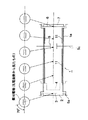
図1は、本発明の実施の形態1に係るストリーク装置の概略断面図である。ストリーク管1は、外囲器として円筒状のガラス管1aを有し、このガラス管1aの内部は、高真空に保持されている。このガラス管1aにおいて、紙面に対して左側の端には、被計測光が入射する入力窓2が設けられており、入力窓2の内面には、光を光電子ビームに変換する光電面3が形成されている。光電面3から紙面に対して右側には、光電子ビームを加速して出力側に向かわせるためのメッシュからなる加速電極4と、光電子を出力面上で掃引するための偏向電極5と、出力面上で光電子の衝撃により電子を光に変換する蛍光面6と、蛍光面6を付着させている真空気密の出力窓7とが管軸に沿って順に設けられている。
【0024】
光電面3は、入力窓2を融着している金属フランジ8aと電気的に接続されており、同様に蛍光面6は、出力窓を融着している金属フランジ8bと電気的に接続されている。加速電極4は、円筒電極4aによって支持されると共に、円筒電極4aを介して金属フランジ8cと電気的に接続されている。また、偏向電極5の偏向板5a、5bは、ガラス管1aの壁に埋め込められた金属製の偏向リード5cと電気的に接続されている。
【0025】
光電面3と加速電極4は、それぞれが電気的に接続された金属フランジ8aを介して加速電圧を印加するための加速電圧発生回路9が接続されている。実施の形態1では、加速電極4はグラウンド電位、光電面3には−10kvが印加されている。蛍光面6が接続されている金属フランジ8bは、グラウンド電位に接続されている。
【0026】
偏向電極5に掃引電圧を印加するための偏向リード5cには、掃引電圧発生回路10が接続されている。掃引動作時は、偏向板5aには図2(a)、偏向板5bには図2(b)にそれぞれ示す1〜2kvp−pの斜状に時間的に変化する掃引電圧が印加される。
【0027】
実施の形態1では、光電面3として、可視光用としてマルチアルカリ光電面を用いている。光電面3から加速電極4の間の距離は5mmで、加速電極4の粗さは1000メッシュ/インチである。加速電極4と蛍光面6との間において、ガラス管1aの内壁には電荷の帯電を防ぐために、アルミニウムを蒸着し、ウォールアノード11を形成している。但し、偏向リード5cの付け根付近はアルミニウムを蒸着せずに電気的にウォールアノード11と偏向リード5cとを絶縁している。また、光電面3から蛍光面6との間の距離は250mmである。
【0028】
ストリーク管1の外周であって加速電極4と偏向電極5との間には、管軸に沿って蛍光面6側から第1集束磁束発生器12aと、第2集束磁束発生器12bとの2つの集束磁束発生器が配置されている。これらの集束磁束発生器12a、12bは、中心軸が管軸と一致するコイルから構成されている。それぞれのコイルには、電流を供給する駆動電源13a、13bが接続されている。
【0029】
第1集束磁束発生器12aは、管軸方向の位置として、光電面3から第1集束磁束発生器12aの中心まで距離と、第1集束磁束発生器12aの中心から蛍光面6までの距離との比がおよそ1.5:1となるように配置されている。
【0030】
本発明の実施の形態1に係るストリーク装置は、▲1▼光電面上で大きな有効範囲を確保することができ、しかもその有効範囲にわたって、空間分解能、時間分解能が良好である。同時に、▲2▼時間分解を行う掃引動作で高いD−レンジを有する。これらは、光電面3から放出された光電子ビームの軌道から理解することができる。まず、▲1▼について説明する。
【0031】
図3(a)は、多チャンネルファイバによる入力を示す図であり、図3(b)は、出力面上のストリーク像を示す図である。例えば、多チャンネル同時時間分解測光等では、図3(a)に示すように、多数のチャンネルファイバ30からの光を、レンズ31を介して光電面3上の中心を通る直線上に結像させる。各チャンネルに対応する微小スポットから放出された光電子ビームは、偏向電極5により掃引され、出力面(蛍光面6)上でストリーク像を得る。
【0032】
図4(a)は、多チャンネルの光電子ビームのうち、光電面3の中心、および中心から最も離れた端部、すなわち空間方向の有効範囲の端で光電面3の中心から8mmの位置における微小スポットから放出された光電子ビームの軌道を示す。また、図4(b)は、蛍光面上の出力スポットを示す図である。図4(a)に示す3つの電子軌道は、実際には管軸方向で集束磁場の存在する場所では、管軸の周りで回転している。ここでは、説明のため、その回転面内での軌道を同一紙面上に描いてある。この回転の関係から、上述した光電面3上に直線状に結像される微小スポット群に対し、偏向電極5に対するその直線の傾きを限定する必要がある。この直線状の各点から放出された光電子ビーム群(図4では、3つのみを示す)は、管軸方向の各位置における断面上で直線上に並んでいる。すなわち、図5において、光電面3における傾きが最も大きく、管軸を中心に回転し、偏向電極5に近づくにつれて偏向板5a、5bに対して平行になっていく。この光電子ビーム群が偏向電極5に入射する時、偏向板5a、5bと平行になるよう、予め光電面3上で直線の傾きを決める必要がある。さもなくば2枚の偏向板5a、5bの間隔が8mm程度と小さいため、光電子ビーム群の端部に近いチャンネルの電子ビームが、偏向板5a又は5bに衝突してしまう。実施の形態1では、光電面3における直線の傾きは偏向板5a、5bに対して、約70度に設定されている。また、各々の光電子ビームは、微小スポットから放出された後、ビームを形成する光電子群が持つ初速度分布のため広がっていくが、集束磁束発生器が発生する集束磁界により、再び出力蛍光面上に結像される。なお、偏向板5a、5bの間隔を8mm程度に小さくしているのは、良好な偏向感度を得るためである。
【0033】
さて、本発明の実施の形態1に係るストリーク装置には、第1集束磁束発生器12a及び第2集束磁束発生器12bが設けられているが、光電面3上の微小スポットの光電子像を出力蛍光面6上に結像させる主たる集束電子レンズを形成するのは、第1集束磁束発生器12aである。この第1集束磁束発生器12aの管軸方向の位置は、次のようにして決まる。
【0034】
先ず、偏向電極5には実質的に集束磁場が作用しないように第1集束磁束発生器12aを偏向電極5の光電面3側に配置する。偏向電極5に集束磁界が存在すると、光電子ビームが磁界に拘束されて偏向感度が下がり、掃引に大きな電圧が必要になると共に、断面が線状の光電子ビームを偏向電極5の入り口で偏向板5a、5bに対して平行に入射させても集束磁界と偏向電界との相乗作用で光電子ビームがサイクロイド運動をして回転する。その結果、線状電子ビームの線方向の長さが大きいと偏向板5a、5bに衝突してしまう。これを回避するため、第1集束磁束発生器12aを偏向電極5の光電面3側に配置する。
【0035】
さらに、主集束電子レンズを形成する第1集束磁束発生器12aの管軸方向の位置を決めるもう一つの要素がある。それは、電子光学系の拡大率、すなわち光電面3上の光像が出力蛍光面6上に何倍に拡大されて結像されるかを示す尺度である。実施の形態1では、光電面3上の有効範囲を大きくするため、有効範囲の端部(光電面3の中心から8mmの位置)に微小スポット光を結像した時、電子光学系の拡大率をMとすれば、そのスポットに対応する蛍光面6上の出力像は、蛍光面6の中心から8Mmmの位置に結像される。従って、拡大率Mが大きいほど出力蛍光面6の有効径を大きくする必要がある。そのため、ストリーク管1が大型化してしまう。また、実施の形態1に係るストリーク管1は、円筒状のガラス管1aを外囲器としているので、出力蛍光面6の有効径が光電面3の有効範囲より大きくなると外囲器の径を出力側で大きくする必要が生じ、構造が複雑になる。そこで、実施の形態1では、拡大率を約1に設定している。ストリーク管1の拡大率は、集束磁束発生器が第1集束磁束発生器12aのみである場合は、ほぼ、(主集束電子レンズの中心−出力掃引面間の距離)/(光電面−主集束電子レンズの中心の距離)の値に等しくなる。実施の形態1に係るストリーク管では、第2集束磁束発生器12bが形成するプリフォーカスレンズを光電面3と第1集束磁束発生器12aとの間に設置しているため、拡大率は、上記の式による値より数割大きくなる。実施の形態1では、前式の比を、上述したように約1/1.5として、約1の拡大率を得ている。
【0036】
次に、プリフォーカスレンズを形成する第2集束磁束発生器12bの役割を、図4を参照して説明する。光電面3において、空間方向の有効範囲の端部で光電面3の中心から8mmの位置の微小スポットから放出された光電子ビームは、このプリフォーカスレンズ40により曲げられて主集束電子レンズ41の中心方向に進む。主集束電子レンズ41の中央部は球面収差が小さいため、出力蛍光面6上にボケの少ないスポットの像が得られる。これにより、時間方向、空間方向の両方向に良好な空間分解能が得られる。一方、図6(a)は、第2集束磁束発生器12bがなく、第1集束磁束発生器12aのみが設けられたストリーク装置において、電子ビームの出力蛍光面上への結像の様子を示す図であり、図6(b)は、蛍光面上の出力スポットを示す図である。光電面3の端部から放出された光電子ビームは、主集束電子レンズ60の球面収差の大きい周辺部分で集束作用を受けるので、出力面上でビームのボケが大きく、空間分解能が劣化する。
【0037】
図7は、多チャンネルの微小スポット群を等間隔で光電面に結像した場合、掃引していないモードで出力蛍光面6に得られるイメージを示す図である。図7(a)は、プリフォーカスレンズ有り、(b)は無しの場合を示している。プリフォーカスレンズを有する方が空間歪みを少なくすることができることがわかる。
【0038】
次に、本発明の実施の形態1に係るストリーク装置が、▲2▼時間分解をする掃引動作で高いD−レンジを有することを、電子軌道等を用いて説明する。図8は、静電集束型のストリーク管81を用いて多チャンネル同時時間分解測光をする時の、管内の電子軌道を示す図である。入力窓82から入射した光は光電面83で光電子に変換される。光電子は加速電極84で加速され、集束電極85で集束されて陽極86に入射する。その後出力蛍光面87に結像する。出力面87は、出力窓88に付着している。この場合、各チャンネルに対応する光電面83上の複数の微小スポットから放出された光電子ビームは、クロスオーバーと呼ばれる点で交叉する。従って、この地点およびこの近辺では、光量が大きくなると、光電子の密度が非常に大きくなり、空間電荷効果により反発しあう。その結果、出力蛍光面87上の電子ビームの結像にボケを発生させ、時間分解能が劣化する。
【0039】
これに対し、図4に示す電磁集束型のストリーク管1の場合は、各微小スポットから放出された光電子は、主集束電子レンズ41の中央部付近に集められるが、図8に示す静電集束型のストリーク管のように1点で交叉することはない。このため、光電子の密度は、管軸方向で最大密度となるところでも、静電集束型に比べ格段と小さい。従って、空間電荷効果によるD−レンジ劣化は小さくなる。また、光電子の密度が最大となるのは、図4に示すように、主集束電子レンズ41の出射面付近であり、このストリーク管1では、主集束電子レンズ41は、先述したようにストリーク管の中央より出力側に近いところに設置されているため、光電子の密度の最大となるところから出力掃引面までの距離が小さくなる。このため、最大密度の部分で空間電荷効果によるクーロン反発力が働いても、それによる光電子ビームの拡散度合いは小さくて済む。その結果、D−レンジ劣化を小さくさせることができる。
【0040】
図9は、本発明の実施の形態1に係る電磁集束型のストリーク管の管軸方向における電位分布を静電集束型のストリーク管と比較して示す図である。静電集束型では、集束電極部の電位が加速電極より低く設定されるので、管軸方向で集束電極部は低速領域となり、光電子ビームを形成する光電子群の空間電荷効果の影響が大きくなる。このため、蛍光面上での電子ビームのボケがより大きくなり、D−レンジが小さくなる。これに対して、電磁集束型では、光電面から放出された光電子ビームは、対向して設けられた加速電極により、10kevまで直ちに加速されるので空間電荷効果の影響を小さくすることができ、D−レンジを大きくすることができる。
【0041】
実施の形態1に係るストリーク管を多チャンネル同時時間分解計測に利用する場合のD−レンジを、図10に示すような配置で評価した。すなわち、時間幅30psのパルスレーザーによって、100μm径のピンホールが11個、1.6mmピッチで1列に開口した黒色シート100を照射する。このピンホール列が拡大率1:1の光学リレーレンズ101により、ストリーク管の光電面3に結像される。従って、光電面3上に結像されたスポット群の両端部間の距離は、16mmである。光電面3上のスポット群から放出された複数の光電子ビームは、集束磁束発生器により蛍光面上に拡大率1で、再結像されるとともに、掃引電極により掃引され、ストリーク像が得られる。その掃引方向の輝度分布の半値幅を、掃引速度で割れば、時間分解能が求められる。
【0042】
図11は、実施の形態1に係るストリーク管の時間分解能Bを、従来の静電集束型のストリーク管の時間分解能Aと比較して示す図である。光パルスの輝度が大きくなると時間分解能が劣化するが、静電集束型に比べ、実施の形態1に係るストリーク管では、その劣化の生じる光量が大きく、D−レンジが大幅に改善されている。
【0043】
(実施の形態2)
次に、本発明の実施の形態2に係るストリーク装置について説明する。実施の形態1では、偏向電極5には実質的に集束磁場が作用しないように第1集束磁束発生器12aを偏向電極5の光電面3側に配置したが、磁場が偏向電極5にも及び、偏向感度が下がったり、偏向電極5で光電子ビームの回転がある程度生じる。この磁場による影響を無視できる程度に小さくするため、実施の形態2では、コイルを軟鉄などの磁性体によりシールドした。図12は、ストリーク管側に開口部120aを有する鉄枠120によってシールドされた集束磁束発生器12aを示す図である。集束磁束は、この開口部120aからストリーク管内に入り、集束作用を行う。図13は、このような磁気シールドを有する場合と、有しない場合との管軸上の磁束密度分布を示す図である。図13に示すように、磁気シールドがある時の方が、ピーク強度からの減衰が早く、偏向電極場への磁場の浸透を無視できるレベルにすることができる。
【0044】
(実施の形態3)
次に、本発明の実施の形態3に係るストリーク装置について説明する。図14は、本発明の実施の形態3に係るストリーク装置の概略断面図である。偏向板5a、5bに掃引電圧が印加される際、偏向板5a、5bには強い電界が生じ、主集束磁束領域にも影響し、時間分解能の低下等の問題が生ずる。これを防ぐため、実施の形態3では、偏向電極5の光電面3側の近傍に、管軸を中心に開口する遮蔽板141を設けた。この遮蔽板141は、金属フランジ142に固定された円筒電極140に保持される。遮蔽板141の電位は、加速電極4の電位と等しくなるように設定される。また、円筒電極140から蛍光面6における電位を加速電極4の電位より低くすれば、偏向感度を上げることも可能である。この金属フランジ142は、ガラス管1aとの融着が必要であるため、主に強磁性体で形成される。強磁性体は集束磁場を乱し、解像度の劣化、歪みの原因となるため、第1集束磁束発生器12aと第2集束磁束発生器12bとののほぼ中間に金属フランジ142を配置させている。
【0045】
(実施の形態4)
次に、本発明の実施の形態4に係るストリーク装置について説明する。図15は、本発明の実施の形態4に係るストリーク装置の光電面付近の一部断面図である。実施の形態4では、光電面3と加速電極4の間に、例えば長さ20mm、幅1mmの開口を有するゲート電極150を設けた。光電面3とゲート電極150の間隔は0.5mmで、ストリーク掃引を行う間は、光電面3に対して+200Vの電圧を印加し、掃引の前後には、光電面3に対して−50Vの電圧を印加する。これにより、掃引を行わない間は光電面3に光が入射しても不要な出力像が生ずることを回避することができ、バックグラウンド上昇を少なくさせることができる。
【0046】
このように、本発明によれば、光電面において、空間方向の有効範囲の端部から放出された光電子ビームが、プリフォーカスレンズにより曲げられて主集束電子レンズの中心方向に進むこととなる。主集束電子レンズの中央部は球面収差が小さいため、出力面上にボケの少ないスポットの像が得られる。これにより、時間方向、空間方向の両方向に良好な空間分解能が得られる。
【0047】
なお、以上説明した各実施の形態では、集束磁束発生器は、プリフォーカスレンズを形成するものと、主集束電子レンズを形成するものについて、それぞれ1つずつ設けたが、それぞれのレンズを形成するのに複数の集束磁束発生器を用いても良い。例えば、プリフォーカスレンズを2個の集束磁束発生器で形成すれば、光電子ビームの軌道をより微妙に制御でき、空間歪みや周辺における空間解像度特性を向上させることができる。また、光電子ビームが掃引されかつ光電子像を可視光像に変換する出力面として、蛍光面を挙げたが、その前に電子増倍作用を有するマイクロチャンネルプレート(MCP)を設置しても良い。また、それらの代わりに電子打ち込み型撮像素子を用いても良い。また、加速電極は、メッシュ電極で説明したが、開口を有する板状電極でも良い。複数の集束磁束発生器は、永久磁石を含み、光電面と偏向電極の入射口との間に永久磁石による磁束を発生させて光電面から放出された光電子を集束させる構成としてもよい。
【0048】
【発明の効果】
以上の説明から明らかなように、本発明によれば、光電面において、空間方向の有効範囲の端部から放出された光電子ビームが、プリフォーカスレンズにより曲げられて主集束電子レンズの中心方向に進むこととなる。主集束電子レンズの中央部は球面収差が小さいため、出力面上にボケの少ないスポットの像が得られる。また、電磁集束型で主集束電子レンズの位置を出力面側(蛍光面側)に近くしているので、空間電荷効果の影響を小さくさせることができ、高いD−レンジ特性を得ることができる。これにより、時間方向、空間方向の両方向に良好な空間分解能を得ることができる。
【図面の簡単な説明】
【図1】 本発明の実施の形態1に係るストリーク装置の概略断面図である。
【図2】 (a) 掃引動作時に偏向板5aに印加される電圧を示す図である。
(b) 掃引動作時に偏向板5bに印加される電圧を示す図である。
【図3】 (a) 多チャンネルファイバによる入力を示す図である。
(b) 出力面上のストリーク像を示す図である。
【図4】 (a) 多チャンネルの光電子ビームのうち、光電面の端部における微小スポットから放出された光電子ビームの軌道を示す図である。
(b) 蛍光面上の出力スポットを示す図である。
【図5】 光電子ビーム群が管軸を中心に回転する様子を示す図である。
【図6】 (a) 単一の集束磁束発生器のみが設けられたストリーク装置において、電子ビームの出力蛍光面上への結像の様子を示す図である。
(b) 蛍光面上の出力スポットを示す図である。
【図7】 (a) プリフォーカスレンズを有する場合、多チャンネルの微小スポット群を等間隔で光電面に結像したときに掃引していないモードで出力蛍光面に得られるイメージを示す図である。
(b) プリフォーカスレンズを有しない場合、多チャンネルの微小スポット群を等間隔で光電面に結像したときに掃引していないモードで出力蛍光面に得られるイメージを示す図である。
【図8】 静電集束型のストリーク管を用いて多チャンネル同時時間分解測光をする時の、管内の電子軌道を示す図である。
【図9】 本発明の実施の形態1に係る電磁集束型のストリーク管の管軸方向における電位分布を静電集束型のストリーク管と比較して示す図である。
【図10】 本発明の実施の形態1に係るストリーク管を多チャンネル同時時間分解計測に利用する場合のD−レンジを評価する図である。
【図11】 本発明の実施の形態1に係るストリーク管の時間分解能Bを、従来の静電集束型のストリーク管の時間分解能Aと比較して示す図である。
【図12】 本発明の実施の形態2に係るストリーク装置、管側に開口部を有する鉄枠によってシールドされた集束磁束発生器を示す図である。
【図13】 磁気シールドを有する場合と、有しない場合との管軸上の磁束密度分布を示す図である。
【図14】 本発明の実施の形態3に係るストリーク装置の概略断面図である。
【図15】 本発明の実施の形態4に係るストリーク装置の光電面付近の一部断面図である。
【符号の説明】
1…ストリーク管、1a…ガラス管、2…入力窓、3…光電面、4a 円筒電極、4…加速電極、5a…偏向板、5b…偏向板、5c…偏向リード、5…偏向電極、6…蛍光面(出力面)、7…出力窓、8a…金属フランジ、8b…金属フランジ、9…加速電圧発生回路、10…掃引電圧発生回路、11…ウォールアノード、12a…集束磁束発生器、12b…集束磁束発生器、13a…駆動電源、120…鉄枠、120a…開口部、140…円筒電極、141…遮蔽板、142…金属フランジ、150…ゲート電極。[0001]
BACKGROUND OF THE INVENTION
The present invention relates to a streak device suitable for measuring intensity distribution over time of a light emission phenomenon.
[0002]
[Prior art]
A streak device is a device that converts a temporal intensity distribution of measured light into a spatial intensity distribution on an output surface. For example, Japanese Patent Publication No. 4-73257 discloses an electromagnetic focusing streak device. This streak device includes a single focusing magnetic flux generator (electromagnetic focusing coil), and this focusing magnetic flux generator generates a focusing magnetic flux only in the space between the photocathode and the entrance of the deflection electrode from the outside of the streak tube. The photoelectrons emitted from the photocathode are substantially focused.
[0003]
[Problems to be solved by the invention]
However, since the above streak device has only one focusing magnetic flux generator, taking a large effective range in the spatial direction on the photocathode, the electron group of photoelectrons emitted from the end of the photocathode, Since it passes through the periphery of the electron lens formed by the focusing magnetic flux generator, there is a problem that the spatial resolution and the temporal resolution are deteriorated and the spatial distortion is increased. In addition, since the distance from the center of the focusing electron lens to the output surface is larger than the distance from the photocathode to the center of the focusing electron lens, it is difficult to increase the effective range in the spatial direction on the photocathode.
[0004]
For example, US Pat. No. 4,350,919 discloses an electromagnetic focusing streak apparatus including two focusing magnetic flux generators. However, in this streak device, since the focusing magnetic field generated by the focusing magnetic flux generator and the deflection electric field generated by the sweeping deflection electrode overlap in the tube axis direction of the streak tube, the photoelectron beam is placed in the scanning deflection electrode. And I do a cycloid movement. For this reason, the effective range in the spatial direction cannot be made large on the photocathode. Also, since the photoelectron beam is affected by the focusing magnetic field, sufficient deflection sensitivity cannot be obtained. Furthermore, the two focusing magnetic field generators of this streak device allow photoelectrons emitted from the end of the photocathode to pass near the center of the electron lens that forms an electron image formed on the photocathode on the output surface. Not arranged to be. For this reason, there is a problem that spatial resolution and temporal resolution at the end of the photocathode deteriorate and spatial distortion increases.
[0005]
On the other hand, the electrostatic focusing type streak device has the advantage that the effective range on the photocathode can be made large, but since the potential of the focusing electrode forming the focusing electron lens is low, the electron beam is generated by the space charge effect. There is a problem of diffusion and a small D-range.
[0006]
The present invention has been made in view of such circumstances, and has a large effective range on the photocathode, a high spatial resolution and a temporal resolution in the effective range, a small spatial distortion, and a D-range. An object of the present invention is to provide a streak device that can be enlarged.
[0007]
[Means for Solving the Problems]
The invention of the streak device according to
[0008]
With this configuration, on the photocathode, the photoelectron beam emitted from the end of the effective range in the spatial direction is bent by the prefocus lens and travels toward the center of the main focusing electron lens. Since the central portion of the main focusing electron lens has small spherical aberration, a spot image with less blur can be obtained on the output surface. Thereby, good spatial resolution can be obtained in both the time direction and the spatial direction.
[0009]
The invention of the streak device according to
[0010]
Thus, a focusing magnetic flux generator can be constituted using a permanent magnet. For this reason, on the photocathode, the photoelectron beam emitted from the end of the effective range in the spatial direction is bent by the prefocus lens and travels toward the center of the main focusing electron lens. Since the central portion of the main focusing electron lens has small spherical aberration, a spot image with less blur can be obtained on the output surface. Thereby, good spatial resolution can be obtained in both the time direction and the spatial direction.
[0011]
According to a third aspect of the present invention, in the streak device according to the first or second aspect, the distance between the center of the main focusing electron lens and the output surface is smaller than the distance between the photoelectric surface and the center of the main focusing electron lens. The structure set to become is adopted.
[0012]
As described above, since the main focusing electron lens is disposed closer to the output side than the center of the streak tube, the distance from the point where the photoelectron density is maximum to the output sweep surface is reduced. For this reason, even if the Coulomb repulsive force due to the space charge effect acts in the maximum density portion, the degree of diffusion of the photoelectron beam due to it is small. As a result, D-range degradation can be reduced.
[0013]
According to a fourth aspect of the present invention, in the streak device according to any one of the first to third aspects, each focusing magnetic flux generator is provided so as to go around the outside of the vacuum vessel, and the central axis coincides with the tube axis. And a magnetic body that shields the coil, and an opening provided on the vacuum container side of the magnetic body.
[0014]
With this configuration, the magnetic field generated by the focused magnetic flux generator can be limited to the required range, and the attenuation from the peak intensity can be accelerated, and the penetration of the magnetic field into the deflection electrode field can be neglected. Can do. For this reason, it can be avoided that the magnetic field reaches the deflection electrode and the deflection sensitivity is lowered or the photoelectron beam is rotated at the deflection electrode.
[0015]
According to a fifth aspect of the present invention, in the streak device according to any one of the first to fourth aspects, the streak tube forms a first focusing magnetic flux generator that forms a main focusing electron lens and a prefocus lens. And a second focusing magnetic flux generator.
[0016]
With this configuration, on the photocathode, the photoelectron beam emitted from the end of the effective range in the spatial direction is bent by the prefocus lens and travels toward the center of the main focusing electron lens. Since the central portion of the main focusing electron lens has small spherical aberration, a spot image with less blur can be obtained on the output surface. Thereby, good spatial resolution can be obtained in both the time direction and the spatial direction.
[0017]
According to a sixth aspect of the present invention, in the streak device according to any one of the first to fifth aspects, the streak tube is provided in the vicinity of the entrance of the deflection electrode and shields the electric field leaking from the deflection electrode. A shield plate that opens about the axis is provided, and the potential of the shield plate is set to be equal to or lower than the potential of the acceleration electrode.
[0018]
With this configuration, it is possible to prevent a strong electric field generated when a sweep voltage is applied to the deflecting plate from leaking to the outside, so that the leaked electric field also affects the main focusing magnetic flux region, resulting in a decrease in time resolution, etc. Can be avoided. Further, the deflection sensitivity can be increased by lowering the potential at the output surface from the shielding plate.
[0019]
According to a seventh aspect of the present invention, in the streak device according to the sixth aspect, the streak tube is provided between the two adjacent magnetic flux generators so as to support the shielding plate and to be electrically connected to the shielding plate. Is further provided.
[0020]
As described above, since the flange is provided in the middle between two adjacent focused magnetic flux generators, it is possible to avoid as much as possible that the flange, which is a ferromagnetic material, disturbs the focused magnetic field, causing deterioration in resolution and distortion.
[0021]
According to an eighth aspect of the present invention, in the streak device according to any one of the first to seventh aspects, the streak tube further includes a gate electrode that opens around the tube axis between the photocathode and the acceleration electrode. Take the configuration.
[0022]
With this configuration, for example, a voltage of +200 V can be applied to the photocathode during the streak sweep, and a voltage of −50 V can be applied to the photocathode before and after the sweep. . For this reason, it is possible to avoid the generation of an unnecessary output image even when light is incident on the photocathode while the sweep is not performed, and the background rise can be reduced.
[0023]
DETAILED DESCRIPTION OF THE INVENTION
(Embodiment 1)
FIG. 1 is a schematic cross-sectional view of a streak device according to
[0024]
The
[0025]
The
[0026]
For deflection electrode 5SweepThe deflection lead 5c for applying a voltage includesSweepA
[0027]
In
[0028]
Between the accelerating
[0029]
The first focused
[0030]
The streak device according to
[0031]
FIG. 3A is a diagram showing input by a multi-channel fiber, and FIG. 3B is a diagram showing a streak image on the output surface. For example, in multi-channel simultaneous time-resolved photometry, etc., as shown in FIG. 3A, light from a number of
[0032]
FIG. 4 (a) shows a microchannel at a position 8 mm from the center of the
[0033]
The streak device according to
[0034]
First, the first focusing
[0035]
Further, there is another element that determines the position of the first focusing
[0036]
Next, the role of the second focusing
[0037]
FIG. 7 is a diagram showing an image obtained on the
[0038]
Next, the fact that the streak device according to
[0039]
On the other hand, in the case of the electromagnetic focusing
[0040]
FIG. 9 is a diagram showing a potential distribution in the tube axis direction of the electromagnetic focusing type streak tube according to the first embodiment of the present invention in comparison with the electrostatic focusing type streak tube. In the electrostatic focusing type, since the potential of the focusing electrode portion is set lower than that of the acceleration electrode, the focusing electrode portion becomes a low speed region in the tube axis direction, and the influence of the space charge effect of the photoelectron group forming the photoelectron beam becomes large. For this reason, the blur of the electron beam on the phosphor screen becomes larger and the D-range becomes smaller. On the other hand, in the electromagnetic focusing type, the photoelectron beam emitted from the photocathode is immediately accelerated to 10 kev by the accelerating electrode provided oppositely, so that the influence of the space charge effect can be reduced. -The range can be increased.
[0041]
The D-range in the case where the streak tube according to
[0042]
FIG. 11 is a diagram showing the time resolution B of the streak tube according to the first embodiment in comparison with the time resolution A of the conventional electrostatic focusing type streak tube. When the luminance of the light pulse increases, the time resolution deteriorates. However, in the streak tube according to the first embodiment, the amount of light generated by the deterioration is large and the D-range is greatly improved.
[0043]
(Embodiment 2)
Next, a streak device according to
[0044]
(Embodiment 3)
Next, a streak device according to
[0045]
(Embodiment 4)
Next, a streak device according to
[0046]
Thus, according to the present invention, on the photocathode, the photoelectron beam emitted from the end of the effective range in the spatial direction is bent by the prefocus lens and travels in the center direction of the main focusing electron lens. Since the central portion of the main focusing electron lens has small spherical aberration, a spot image with less blur can be obtained on the output surface. Thereby, good spatial resolution can be obtained in both the time direction and the spatial direction.
[0047]
In each of the embodiments described above, the focusing magnetic flux generator includes a prefocus lens and a main focusing lens.ElectronicAlthough one lens is provided for each lens, a plurality of focused magnetic flux generators may be used to form each lens. For example, if the prefocus lens is formed by two focused magnetic flux generators, the trajectory of the photoelectron beam can be controlled more finely, and spatial distortion and spatial resolution characteristics in the periphery can be improved. In addition, although the phosphor screen is mentioned as the output surface for sweeping the photoelectron beam and converting the photoelectron image into the visible light image, a microchannel plate (MCP) having an electron multiplying action may be installed in front of it. Moreover, you may use an electron implantation type image pick-up element instead of them. Moreover, although the acceleration electrode was demonstrated with the mesh electrode, the plate-shaped electrode which has opening may be sufficient.The plurality of focused magnetic flux generators may include a permanent magnet, and may generate a magnetic flux generated by the permanent magnet between the photocathode and the entrance of the deflection electrode to focus the photoelectrons emitted from the photocathode.
[0048]
【The invention's effect】
As is clear from the above description, according to the present invention, on the photocathode, the photoelectron beam emitted from the end of the effective range in the spatial direction is bent by the prefocus lens toward the center of the main focusing electron lens. It will go on. Since the central portion of the main focusing electron lens has small spherical aberration, a spot image with less blur can be obtained on the output surface. In addition, since the position of the main focusing electron lens is close to the output surface side (phosphor surface side) in the electromagnetic focusing type, the influence of the space charge effect can be reduced, and high D-range characteristics can be obtained. . Thereby, favorable spatial resolution can be obtained in both the time direction and the spatial direction.
[Brief description of the drawings]
FIG. 1 is a schematic cross-sectional view of a streak device according to
FIG. 2 (a)SweepIt is a figure which shows the voltage applied to the deflection |
(B)SweepIt is a figure which shows the voltage applied to the deflection |
FIG. 3A is a diagram showing input through a multi-channel fiber.
(B) It is a figure which shows the streak image on an output surface.
FIG. 4A is a diagram showing a trajectory of a photoelectron beam emitted from a minute spot at an end of a photocathode among multi-channel photoelectron beams.
(B) It is a figure which shows the output spot on a fluorescent screen.
FIG. 5 is a diagram showing a state in which a photoelectron beam group rotates around a tube axis.
FIG. 6A is a diagram showing a state of image formation on an output fluorescent screen of an electron beam in a streak apparatus provided with only a single focused magnetic flux generator.
(B) It is a figure which shows the output spot on a fluorescent screen.
FIG. 7A is a diagram showing an image obtained on an output phosphor screen in a mode in which no sweeping is performed when a multi-channel minute spot group is imaged on a photocathode at equal intervals when a prefocus lens is provided. .
(B) When there is no prefocus lens, it is a figure which shows the image obtained on an output fluorescent screen in the mode which is not swept when a multichannel microspot group is imaged on a photoelectric surface at equal intervals.
FIG. 8 is a diagram showing electron trajectories in a tube when performing multichannel simultaneous time-resolved photometry using an electrostatic focusing streak tube.
FIG. 9 is a diagram showing a potential distribution in the tube axis direction of the electromagnetic focusing type streak tube according to the first embodiment of the present invention in comparison with an electrostatic focusing type streak tube.
FIG. 10 is a diagram for evaluating a D-range when the streak tube according to the first embodiment of the present invention is used for multi-channel simultaneous time-resolved measurement.
FIG. 11 is a diagram showing the time resolution B of the streak tube according to the first embodiment of the present invention in comparison with the time resolution A of a conventional electrostatic focusing type streak tube.
12 is a diagram showing a streak device according to a second embodiment of the present invention and a focused magnetic flux generator shielded by an iron frame having an opening on the tube side. FIG.
FIG. 13 is a diagram showing the magnetic flux density distribution on the tube axis with and without a magnetic shield.
FIG. 14 is a schematic cross-sectional view of a streak device according to
FIG. 15 is a partial cross-sectional view of the vicinity of the photocathode of the streak device according to
[Explanation of symbols]
DESCRIPTION OF
Claims (8)
前記偏向電極に偏向電界を発生させる電圧を供給する偏向電圧発生回路と、
前記加速電極に電圧を供給する加速電圧発生回路と、
前記集束磁束発生器に電流を供給する駆動電源と、を備えるストリーク装置において、
前記複数の集束磁束発生器は、
前記光電面上に形成された電子像を前記出力面上に結像させる主集束電子レンズと、
前記光電面と前記主集束電子レンズとの間に設けられ、前記光電面から放出された光電子を前記主集束電子レンズの中心方向に集束させるプリフォーカスレンズと、を形成することを特徴とするストリーク装置。A vacuum vessel provided at one end with a photocathode that converts received light into photoelectrons at one end, and an output surface that converts an image of the photoelectrons into a visible light image at the other end; and the photocathode along the tube axis of the vacuum vessel; An accelerating electrode arranged to oppose and accelerate the photoelectrons emitted from the photocathode, and a deflection electrode comprising a pair of electrodes opposed to sandwich the tube axis between the accelerating electrode and the output surface; A streak tube comprising: a plurality of focused magnetic flux generators for generating a focused magnetic flux between the photocathode and an entrance of the deflection electrode to focus photoelectrons emitted from the photocathode;
A deflection voltage generation circuit for supplying a voltage for generating a deflection electric field to the deflection electrode;
An acceleration voltage generating circuit for supplying a voltage to the acceleration electrode;
A streak device comprising: a driving power source for supplying current to the focused magnetic flux generator;
The plurality of focused magnetic flux generators are:
A main focusing electron lens that forms an electron image formed on the photocathode on the output surface;
A streak formed between the photocathode and the main focusing electron lens and configured to focus photoelectrons emitted from the photocathode in the central direction of the main focusing electron lens. apparatus.
前記偏向電極に偏向電界を発生させる電圧を供給する偏向電圧発生回路と、
前記加速電極に電圧を供給する加速電圧発生回路と、を備えるストリーク装置において、
前記複数の集束磁束発生器は、
前記光電面上に形成された電子像を前記出力面上に結像させる主集束電子レンズと、
前記光電面と前記主集束電子レンズとの間に設けられ、前記光電面から放出された光電子を前記主集束電子レンズの中心方向に集束させるプリフォーカスレンズと、を形成することを特徴とするストリーク装置。A vacuum vessel provided at one end with a photocathode that converts received light into photoelectrons at one end, and an output surface that converts an image of the photoelectrons into a visible light image at the other end; and the photocathode along the tube axis of the vacuum vessel; An accelerating electrode arranged to oppose and accelerate the photoelectrons emitted from the photocathode, and a deflection electrode comprising a pair of electrodes opposed to sandwich the tube axis between the accelerating electrode and the output surface; A streak tube comprising a plurality of focusing magnetic flux generators including a permanent magnet and focusing a photoelectron emitted from the photocathode by generating a magnetic flux by the permanent magnet between the photocathode and an entrance of the deflection electrode When,
A deflection voltage generation circuit for supplying a voltage for generating a deflection electric field to the deflection electrode;
In a streak device comprising an acceleration voltage generation circuit for supplying a voltage to the acceleration electrode,
The plurality of focused magnetic flux generators are:
A main focusing electron lens that forms an electron image formed on the photocathode on the output surface;
A streak formed between the photocathode and the main focusing electron lens and configured to focus photoelectrons emitted from the photocathode in the central direction of the main focusing electron lens. apparatus.
Priority Applications (6)
| Application Number | Priority Date | Filing Date | Title |
|---|---|---|---|
| JP2000003781A JP4429447B2 (en) | 2000-01-12 | 2000-01-12 | Streak device |
| DE60134719T DE60134719D1 (en) | 2000-01-12 | 2001-01-11 | STREAK DEVICE |
| EP01900668A EP1253618B1 (en) | 2000-01-12 | 2001-01-11 | Streak device |
| US10/169,861 US7196723B2 (en) | 2000-01-12 | 2001-01-11 | Streak apparatus with focus |
| PCT/JP2001/000091 WO2001052300A1 (en) | 2000-01-12 | 2001-01-11 | Streak device |
| AU2001225491A AU2001225491A1 (en) | 2000-01-12 | 2001-01-11 | Streak device |
Applications Claiming Priority (1)
| Application Number | Priority Date | Filing Date | Title |
|---|---|---|---|
| JP2000003781A JP4429447B2 (en) | 2000-01-12 | 2000-01-12 | Streak device |
Publications (3)
| Publication Number | Publication Date |
|---|---|
| JP2001196018A JP2001196018A (en) | 2001-07-19 |
| JP2001196018A5 JP2001196018A5 (en) | 2008-07-31 |
| JP4429447B2 true JP4429447B2 (en) | 2010-03-10 |
Family
ID=18532666
Family Applications (1)
| Application Number | Title | Priority Date | Filing Date |
|---|---|---|---|
| JP2000003781A Expired - Fee Related JP4429447B2 (en) | 2000-01-12 | 2000-01-12 | Streak device |
Country Status (6)
| Country | Link |
|---|---|
| US (1) | US7196723B2 (en) |
| EP (1) | EP1253618B1 (en) |
| JP (1) | JP4429447B2 (en) |
| AU (1) | AU2001225491A1 (en) |
| DE (1) | DE60134719D1 (en) |
| WO (1) | WO2001052300A1 (en) |
Families Citing this family (12)
| Publication number | Priority date | Publication date | Assignee | Title |
|---|---|---|---|---|
| CN100423170C (en) * | 2005-04-22 | 2008-10-01 | 中国科学院物理研究所 | Electron beam generating and controlling device |
| US8098364B2 (en) * | 2007-10-19 | 2012-01-17 | Taiwan Semiconductor Manufacturing Company, Ltd. | Exposure apparatus and method for photolithography process |
| CN101852859B (en) * | 2010-06-21 | 2012-07-04 | 西安理工大学 | Photon counter based on magnetic mirror and method for detecting photon |
| CN102024651A (en) * | 2010-10-13 | 2011-04-20 | 深圳大学 | Time focusing and time collimating method and device of ultra-short electron beam bunch |
| JP2018129559A (en) * | 2015-06-19 | 2018-08-16 | 江藤 剛治 | High-speed imaging apparatus |
| CN107703712B (en) * | 2017-11-13 | 2023-11-14 | 中国工程物理研究院激光聚变研究中心 | Hard X-ray stripe camera and method for detecting hard X-ray energy section thereof |
| US10197441B1 (en) * | 2018-01-30 | 2019-02-05 | Applied Materials Israel Ltd. | Light detector and a method for detecting light |
| US11302510B2 (en) * | 2018-05-29 | 2022-04-12 | Kla-Tencor Corporation | Space charge insensitive electron gun designs |
| US11268849B2 (en) | 2019-04-22 | 2022-03-08 | Applied Materials Israel Ltd. | Sensing unit having photon to electron converter and a method |
| CN110534387A (en) * | 2019-09-06 | 2019-12-03 | 湖北大学 | A kind of ferroelectric ceramics boundling electronic emitter |
| WO2022021140A1 (en) * | 2020-07-29 | 2022-02-03 | 深圳大学 | Visible light streak tube and electron-optical imaging system |
| CN113130278B (en) * | 2021-04-21 | 2022-07-12 | 中国工程物理研究院激光聚变研究中心 | Low-noise long-cathode scanning image converter tube |
Family Cites Families (15)
| Publication number | Priority date | Publication date | Assignee | Title |
|---|---|---|---|---|
| US4350919A (en) * | 1977-09-19 | 1982-09-21 | International Telephone And Telegraph Corporation | Magnetically focused streak tube |
| GB2133611A (en) | 1982-11-29 | 1984-07-25 | Masao Kaneko | Radiographic magnifying device |
| JPS59101134A (en) * | 1982-11-29 | 1984-06-11 | 浜松ホトニクス株式会社 | Radiation image enlarging apparatus |
| JPS59191243A (en) * | 1983-04-15 | 1984-10-30 | Hamamatsu Photonics Kk | Image magnifying tube |
| JPS59191244A (en) * | 1983-04-15 | 1984-10-30 | Hamamatsu Photonics Kk | Image magnification device |
| JPS59194334A (en) * | 1983-04-19 | 1984-11-05 | Hamamatsu Photonics Kk | Picture magnifying device |
| JPH0623669B2 (en) * | 1986-06-27 | 1994-03-30 | 浜松ホトニクス株式会社 | Stroke device |
| FR2615654B1 (en) * | 1987-05-22 | 1989-07-28 | Sodern | LINE COMPENSATION IMAGE ANALYZER TUBE |
| JPH02239554A (en) * | 1989-03-14 | 1990-09-21 | Hamamatsu Photonics Kk | Streak tube |
| JP2857181B2 (en) * | 1989-10-20 | 1999-02-10 | 浜松ホトニクス株式会社 | Image tube equipment |
| JPH0727762B2 (en) * | 1989-12-01 | 1995-03-29 | 浜松ホトニクス株式会社 | Streak tube |
| JPH0697737B2 (en) * | 1990-01-12 | 1994-11-30 | 浜松ホトニクス株式会社 | Staircase generator |
| JPH062980B2 (en) | 1990-07-13 | 1994-01-12 | 株式会社データアクション | Fiber discoloration prevention method |
| US5278403A (en) * | 1991-04-29 | 1994-01-11 | Alfano Robert R | Femtosecond streak camera |
| JP3305083B2 (en) * | 1993-12-22 | 2002-07-22 | キヤノン株式会社 | Optical radar |
-
2000
- 2000-01-12 JP JP2000003781A patent/JP4429447B2/en not_active Expired - Fee Related
-
2001
- 2001-01-11 AU AU2001225491A patent/AU2001225491A1/en not_active Abandoned
- 2001-01-11 EP EP01900668A patent/EP1253618B1/en not_active Expired - Lifetime
- 2001-01-11 WO PCT/JP2001/000091 patent/WO2001052300A1/en active IP Right Grant
- 2001-01-11 US US10/169,861 patent/US7196723B2/en not_active Expired - Lifetime
- 2001-01-11 DE DE60134719T patent/DE60134719D1/en not_active Expired - Lifetime
Also Published As
| Publication number | Publication date |
|---|---|
| US7196723B2 (en) | 2007-03-27 |
| WO2001052300A1 (en) | 2001-07-19 |
| US20030001496A1 (en) | 2003-01-02 |
| JP2001196018A (en) | 2001-07-19 |
| EP1253618A4 (en) | 2003-04-23 |
| EP1253618B1 (en) | 2008-07-09 |
| DE60134719D1 (en) | 2008-08-21 |
| EP1253618A1 (en) | 2002-10-30 |
| AU2001225491A1 (en) | 2001-07-24 |
Similar Documents
| Publication | Publication Date | Title |
|---|---|---|
| KR100494298B1 (en) | Scanning electron microscope | |
| JP4429447B2 (en) | Streak device | |
| JPH0536371A (en) | Corpuscular ray device | |
| JP6826218B2 (en) | How to operate the electronic shock detector | |
| CA1054209A (en) | Streak camera tube | |
| US4350919A (en) | Magnetically focused streak tube | |
| US4000432A (en) | Magnetic shield for image intensifier tube | |
| US3792263A (en) | Scanning electron microscope with means to remove low energy electrons from the primary electron beam | |
| EP0430718B1 (en) | A streak camera | |
| JP2572388B2 (en) | Strike tube | |
| JP3432091B2 (en) | Scanning electron microscope | |
| JP2002324510A (en) | Scanning electron microscope | |
| JP2002025492A (en) | Method and apparatus for imaging sample using low profile electron detector for charged particle beam imaging system containing electrostatic mirror | |
| JP5824328B2 (en) | Streak tube and streak device including the same | |
| JP6401600B2 (en) | Streak tube and streak device including the same | |
| RU2100867C1 (en) | Pulse electrooptical transducer for time analysis of images | |
| JPH03295141A (en) | Detector | |
| JPS61153934A (en) | Variable focus x-ray tube | |
| SU1272376A1 (en) | Time-analyzing electron-optical image converter | |
| JP4382424B2 (en) | Multi-emitter evaluation method and multi-emitter evaluation apparatus | |
| JPS6119034A (en) | Streaking device | |
| RU2106715C1 (en) | Electron optical camera | |
| JP2001110350A (en) | Charged particle beam apparatus | |
| JPH10208678A (en) | Electron microscope | |
| JPH0479466B2 (en) |
Legal Events
| Date | Code | Title | Description |
|---|---|---|---|
| A621 | Written request for application examination |
Free format text: JAPANESE INTERMEDIATE CODE: A621 Effective date: 20061226 |
|
| A521 | Request for written amendment filed |
Free format text: JAPANESE INTERMEDIATE CODE: A523 Effective date: 20080613 |
|
| TRDD | Decision of grant or rejection written | ||
| A01 | Written decision to grant a patent or to grant a registration (utility model) |
Free format text: JAPANESE INTERMEDIATE CODE: A01 Effective date: 20091215 |
|
| A01 | Written decision to grant a patent or to grant a registration (utility model) |
Free format text: JAPANESE INTERMEDIATE CODE: A01 |
|
| A61 | First payment of annual fees (during grant procedure) |
Free format text: JAPANESE INTERMEDIATE CODE: A61 Effective date: 20091216 |
|
| FPAY | Renewal fee payment (event date is renewal date of database) |
Free format text: PAYMENT UNTIL: 20121225 Year of fee payment: 3 |
|
| R150 | Certificate of patent or registration of utility model |
Ref document number: 4429447 Country of ref document: JP Free format text: JAPANESE INTERMEDIATE CODE: R150 Free format text: JAPANESE INTERMEDIATE CODE: R150 |
|
| FPAY | Renewal fee payment (event date is renewal date of database) |
Free format text: PAYMENT UNTIL: 20131225 Year of fee payment: 4 |
|
| LAPS | Cancellation because of no payment of annual fees |