JP4429187B2 - Information processing apparatus, imaging apparatus, and system - Google Patents
Information processing apparatus, imaging apparatus, and system Download PDFInfo
- Publication number
- JP4429187B2 JP4429187B2 JP2005046225A JP2005046225A JP4429187B2 JP 4429187 B2 JP4429187 B2 JP 4429187B2 JP 2005046225 A JP2005046225 A JP 2005046225A JP 2005046225 A JP2005046225 A JP 2005046225A JP 4429187 B2 JP4429187 B2 JP 4429187B2
- Authority
- JP
- Japan
- Prior art keywords
- dubbing
- unit
- communication
- data
- imaging
- Prior art date
- Legal status (The legal status is an assumption and is not a legal conclusion. Google has not performed a legal analysis and makes no representation as to the accuracy of the status listed.)
- Expired - Fee Related
Links
- 238000003384 imaging method Methods 0.000 title claims description 79
- 230000010365 information processing Effects 0.000 title claims description 21
- 238000000034 method Methods 0.000 claims description 99
- 230000008569 process Effects 0.000 claims description 87
- 238000004891 communication Methods 0.000 claims description 79
- 230000004044 response Effects 0.000 claims description 79
- 238000012545 processing Methods 0.000 claims description 43
- 230000003287 optical effect Effects 0.000 claims description 34
- 230000005540 biological transmission Effects 0.000 claims description 19
- 230000006870 function Effects 0.000 claims description 14
- 238000001514 detection method Methods 0.000 claims description 12
- 238000012546 transfer Methods 0.000 claims description 12
- 230000007704 transition Effects 0.000 claims description 10
- 238000004590 computer program Methods 0.000 claims description 4
- 230000014759 maintenance of location Effects 0.000 claims 1
- 238000010586 diagram Methods 0.000 description 4
- 238000013500 data storage Methods 0.000 description 3
- 230000008859 change Effects 0.000 description 2
- 238000003825 pressing Methods 0.000 description 2
- 101150117538 Set2 gene Proteins 0.000 description 1
- 238000007796 conventional method Methods 0.000 description 1
- 238000005516 engineering process Methods 0.000 description 1
- 239000004973 liquid crystal related substance Substances 0.000 description 1
- 230000000717 retained effect Effects 0.000 description 1
Images


Classifications
-
- G—PHYSICS
- G11—INFORMATION STORAGE
- G11B—INFORMATION STORAGE BASED ON RELATIVE MOVEMENT BETWEEN RECORD CARRIER AND TRANSDUCER
- G11B27/00—Editing; Indexing; Addressing; Timing or synchronising; Monitoring; Measuring tape travel
- G11B27/10—Indexing; Addressing; Timing or synchronising; Measuring tape travel
- G11B27/34—Indicating arrangements
-
- H—ELECTRICITY
- H04—ELECTRIC COMMUNICATION TECHNIQUE
- H04N—PICTORIAL COMMUNICATION, e.g. TELEVISION
- H04N1/00—Scanning, transmission or reproduction of documents or the like, e.g. facsimile transmission; Details thereof
- H04N1/00127—Connection or combination of a still picture apparatus with another apparatus, e.g. for storage, processing or transmission of still picture signals or of information associated with a still picture
- H04N1/00204—Connection or combination of a still picture apparatus with another apparatus, e.g. for storage, processing or transmission of still picture signals or of information associated with a still picture with a digital computer or a digital computer system, e.g. an internet server
-
- H—ELECTRICITY
- H04—ELECTRIC COMMUNICATION TECHNIQUE
- H04N—PICTORIAL COMMUNICATION, e.g. TELEVISION
- H04N21/00—Selective content distribution, e.g. interactive television or video on demand [VOD]
- H04N21/40—Client devices specifically adapted for the reception of or interaction with content, e.g. set-top-box [STB]; Operations thereof
- H04N21/41—Structure of client; Structure of client peripherals
- H04N21/4104—Peripherals receiving signals from specially adapted client devices
- H04N21/4113—PC
-
- H—ELECTRICITY
- H04—ELECTRIC COMMUNICATION TECHNIQUE
- H04N—PICTORIAL COMMUNICATION, e.g. TELEVISION
- H04N21/00—Selective content distribution, e.g. interactive television or video on demand [VOD]
- H04N21/40—Client devices specifically adapted for the reception of or interaction with content, e.g. set-top-box [STB]; Operations thereof
- H04N21/41—Structure of client; Structure of client peripherals
- H04N21/414—Specialised client platforms, e.g. receiver in car or embedded in a mobile appliance
- H04N21/4147—PVR [Personal Video Recorder]
-
- H—ELECTRICITY
- H04—ELECTRIC COMMUNICATION TECHNIQUE
- H04N—PICTORIAL COMMUNICATION, e.g. TELEVISION
- H04N21/00—Selective content distribution, e.g. interactive television or video on demand [VOD]
- H04N21/40—Client devices specifically adapted for the reception of or interaction with content, e.g. set-top-box [STB]; Operations thereof
- H04N21/41—Structure of client; Structure of client peripherals
- H04N21/422—Input-only peripherals, i.e. input devices connected to specially adapted client devices, e.g. global positioning system [GPS]
- H04N21/4223—Cameras
-
- H—ELECTRICITY
- H04—ELECTRIC COMMUNICATION TECHNIQUE
- H04N—PICTORIAL COMMUNICATION, e.g. TELEVISION
- H04N21/00—Selective content distribution, e.g. interactive television or video on demand [VOD]
- H04N21/40—Client devices specifically adapted for the reception of or interaction with content, e.g. set-top-box [STB]; Operations thereof
- H04N21/41—Structure of client; Structure of client peripherals
- H04N21/426—Internal components of the client ; Characteristics thereof
- H04N21/42646—Internal components of the client ; Characteristics thereof for reading from or writing on a non-volatile solid state storage medium, e.g. DVD, CD-ROM
-
- H—ELECTRICITY
- H04—ELECTRIC COMMUNICATION TECHNIQUE
- H04N—PICTORIAL COMMUNICATION, e.g. TELEVISION
- H04N21/00—Selective content distribution, e.g. interactive television or video on demand [VOD]
- H04N21/40—Client devices specifically adapted for the reception of or interaction with content, e.g. set-top-box [STB]; Operations thereof
- H04N21/43—Processing of content or additional data, e.g. demultiplexing additional data from a digital video stream; Elementary client operations, e.g. monitoring of home network or synchronising decoder's clock; Client middleware
- H04N21/436—Interfacing a local distribution network, e.g. communicating with another STB or one or more peripheral devices inside the home
- H04N21/4363—Adapting the video or multiplex stream to a specific local network, e.g. a IEEE 1394 or Bluetooth® network
- H04N21/43632—Adapting the video or multiplex stream to a specific local network, e.g. a IEEE 1394 or Bluetooth® network involving a wired protocol, e.g. IEEE 1394
-
- H—ELECTRICITY
- H04—ELECTRIC COMMUNICATION TECHNIQUE
- H04N—PICTORIAL COMMUNICATION, e.g. TELEVISION
- H04N21/00—Selective content distribution, e.g. interactive television or video on demand [VOD]
- H04N21/40—Client devices specifically adapted for the reception of or interaction with content, e.g. set-top-box [STB]; Operations thereof
- H04N21/43—Processing of content or additional data, e.g. demultiplexing additional data from a digital video stream; Elementary client operations, e.g. monitoring of home network or synchronising decoder's clock; Client middleware
- H04N21/442—Monitoring of processes or resources, e.g. detecting the failure of a recording device, monitoring the downstream bandwidth, the number of times a movie has been viewed, the storage space available from the internal hard disk
- H04N21/44231—Monitoring of peripheral device or external card, e.g. to detect processing problems in a handheld device or the failure of an external recording device
-
- H—ELECTRICITY
- H04—ELECTRIC COMMUNICATION TECHNIQUE
- H04N—PICTORIAL COMMUNICATION, e.g. TELEVISION
- H04N21/00—Selective content distribution, e.g. interactive television or video on demand [VOD]
- H04N21/40—Client devices specifically adapted for the reception of or interaction with content, e.g. set-top-box [STB]; Operations thereof
- H04N21/45—Management operations performed by the client for facilitating the reception of or the interaction with the content or administrating data related to the end-user or to the client device itself, e.g. learning user preferences for recommending movies, resolving scheduling conflicts
- H04N21/462—Content or additional data management, e.g. creating a master electronic program guide from data received from the Internet and a Head-end, controlling the complexity of a video stream by scaling the resolution or bit-rate based on the client capabilities
- H04N21/4627—Rights management associated to the content
-
- H—ELECTRICITY
- H04—ELECTRIC COMMUNICATION TECHNIQUE
- H04N—PICTORIAL COMMUNICATION, e.g. TELEVISION
- H04N23/00—Cameras or camera modules comprising electronic image sensors; Control thereof
- H04N23/60—Control of cameras or camera modules
- H04N23/66—Remote control of cameras or camera parts, e.g. by remote control devices
-
- H—ELECTRICITY
- H04—ELECTRIC COMMUNICATION TECHNIQUE
- H04N—PICTORIAL COMMUNICATION, e.g. TELEVISION
- H04N5/00—Details of television systems
- H04N5/76—Television signal recording
- H04N5/765—Interface circuits between an apparatus for recording and another apparatus
-
- H—ELECTRICITY
- H04—ELECTRIC COMMUNICATION TECHNIQUE
- H04N—PICTORIAL COMMUNICATION, e.g. TELEVISION
- H04N5/00—Details of television systems
- H04N5/76—Television signal recording
- H04N5/765—Interface circuits between an apparatus for recording and another apparatus
- H04N5/77—Interface circuits between an apparatus for recording and another apparatus between a recording apparatus and a television camera
- H04N5/772—Interface circuits between an apparatus for recording and another apparatus between a recording apparatus and a television camera the recording apparatus and the television camera being placed in the same enclosure
-
- H—ELECTRICITY
- H04—ELECTRIC COMMUNICATION TECHNIQUE
- H04N—PICTORIAL COMMUNICATION, e.g. TELEVISION
- H04N2101/00—Still video cameras
-
- H—ELECTRICITY
- H04—ELECTRIC COMMUNICATION TECHNIQUE
- H04N—PICTORIAL COMMUNICATION, e.g. TELEVISION
- H04N2201/00—Indexing scheme relating to scanning, transmission or reproduction of documents or the like, and to details thereof
- H04N2201/0008—Connection or combination of a still picture apparatus with another apparatus
- H04N2201/0013—Arrangements for the control of the connected apparatus by the still picture apparatus
-
- H—ELECTRICITY
- H04—ELECTRIC COMMUNICATION TECHNIQUE
- H04N—PICTORIAL COMMUNICATION, e.g. TELEVISION
- H04N2201/00—Indexing scheme relating to scanning, transmission or reproduction of documents or the like, and to details thereof
- H04N2201/0008—Connection or combination of a still picture apparatus with another apparatus
- H04N2201/0015—Control of image communication with the connected apparatus, e.g. signalling capability
-
- H—ELECTRICITY
- H04—ELECTRIC COMMUNICATION TECHNIQUE
- H04N—PICTORIAL COMMUNICATION, e.g. TELEVISION
- H04N2201/00—Indexing scheme relating to scanning, transmission or reproduction of documents or the like, and to details thereof
- H04N2201/0008—Connection or combination of a still picture apparatus with another apparatus
- H04N2201/0034—Details of the connection, e.g. connector, interface
- H04N2201/0048—Type of connection
- H04N2201/0049—By wire, cable or the like
Description
本発明は、デジタルビデオカメラ等の撮像装置に記憶保持されたデータファイルのダビングもしくはバックアップ技術に関するものである。 The present invention relates to a dubbing or backup technique for data files stored and held in an imaging apparatus such as a digital video camera.
デジタルカメラやデジタルビデオカメラ等の撮像装置において記録された画像データを、パーソナルコンピュータ(以下、PC)内の大容量記録装置(ハードディスク等)に移動して保存したり、或いは書き込み可能なDVDやCD等の光ディスクのようなランダムアクセスメディアに保存しておく使用形態が一般的に行われている。 Image data recorded by an imaging device such as a digital camera or digital video camera can be moved to a large-capacity recording device (such as a hard disk) in a personal computer (hereinafter referred to as a PC) for storage or writing or writing on a DVD or CD In general, there is a usage pattern in which the data is stored in a random access medium such as an optical disk.
この場合、ユーザーはデジタルカメラもしくは、デジタルビデオカメラの記録媒体、例えばコンパクトフラッシュ(登録商標)、SDカード、メモリースティック、DVD等の媒体を、PCのメモリアダプタに装着し、PC側の大容量記録装置に転送記録を行う。或いは、PCが前記メモリアダプタを具備していない場合には、PCとデジタルカメラもしくは、デジタルビデオカメラをデジタルインターフェース、例えばUSBやIEEE1394の様な高速シリアルインターフェースで接続し、記録媒体上のデータをPC側で読出し、大容量記録装置に転送記録する。どちらの場合も、ユーザーはPC上のアプリケーションによって、ソースの記録媒体から大容量記録装置への転送を指定して実行しなければならない。 In this case, the user attaches a recording medium of a digital camera or digital video camera, for example, a compact flash (registered trademark), an SD card, a memory stick, a DVD or the like to a memory adapter of a PC, and a large-capacity recording device on the PC side Make a transfer record. Alternatively, if the PC does not include the memory adapter, the PC and the digital camera or digital video camera are connected by a digital interface, for example, a high-speed serial interface such as USB or IEEE1394, and the data on the recording medium is transferred to the PC. Read out and transferred to a large-capacity recording device. In either case, the user must designate and execute transfer from the source recording medium to the mass storage device by an application on the PC.
図1は、DVDメディアカセット等のランダムアクセスメディア102を記録媒体として使用するデジタルビデオカメラ101と、大容量記録装置104が接続されたPC103とが、USBインターフェースケーブル(当然、双方にはUSBインタフェースを備える)によって接続された状態を示している。
FIG. 1 shows a
PC103はUSBホストとして動作し、デジタルビデオカメラ101はUSBデバイス(スレーブ)として動作している。USBホストが、USBインターフェースを介してUSBデバイスからデータを取得する場合には、例えば、“Universal Serial Bus Still Image Capture Device Definition Revision 1.0 July 11,2000(以降PTP)”や、“Universal Serial Bus Mass Storage Class Bulk-Only Transport Revision 1.0 September 31, 1999(以降マスストレージ)”等の規格に従って通信を行うのが一般的である。
The PC 103 operates as a USB host, and the
図1の例では後者のマスストレージに準拠して通信を行うものとして説明する。 In the example of FIG. 1, description will be made assuming that communication is performed in accordance with the latter mass storage.
PC103は、USBインターフェースケーブル105を介して、デジタルビデオカメラ101の接続を検出すると、デジタルビデオカメラ101からディスクリプタ情報を取得し、デバイス情報の判別、通信方法の判別を行い、デジタルビデオカメラ101がマスストレージクラスのデバイスとして認識する。その後、マスストレージに従って、データの取得を行うことになるが、この場合にはPC103上のアプリケーションをユーザーが操作することによって以降の動作が実行可能となる。
When the PC 103 detects the connection of the
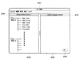
図2は前記アプリケーションの例である。このアプリケーションは、外部の機器からデータを読み出し、任意の記録媒体に記録保存するアプリケーションである。ユーザーはデータ保存アプリケーション201をデジタルビデオカメラ101をPC103に接続した後に起動する必要がある。このアプリケーションでは、デジタルビデオカメラ101の記録媒体に記録された映像データ一覧が表示領域203に示され、これらのデータがデジタルビデオカメラドライブの記録媒体にあることをタイトルバー(202)によって示している。タイトルバー204は記録先の記録装置をしめしており、この状態においては、記録先は大容量記録装置104を示している。ここで、ユーザーによりアプリケーション上のコピーボタン206がクリックされると、デジタルビデオカメラの記録媒体内にある所望のデータが、大容量記録装置104の指定されたフォルダにコピーされることになり、動作完了後、そのコピーされた結果が表示領域205に表示される。ただし、この例は説明を簡単にするものであり、実際のアプリケーションは例えば、記録元となる映像データをサムネイル形式で表示させたり、また、記録するデータを選択できたり、また、記録先を大容量記録装置104ではなく、別の記録装置、例えば、CD-RWやDVD-RWといった光ディスク記録装置を選択できる仕様が一般的である。
FIG. 2 is an example of the application. This application is an application that reads data from an external device and records and saves the data in an arbitrary recording medium. The user needs to start the
実際にコピーボタン206がクリックされると、データ保存アプリケーション201は、PC103のUSBドライバおよびマスストレージドライバにアクセスすることで、データの読み出しをマスストレージに準拠して受信を開始する。ここでマスストレージの動作シーケンスを簡単に説明すると、USBのマスストレージホストとしてのPC103は、マスストレージデバイスであるデジタルビデオカメラ101に対してCommand Block Wrapper(CBW)を送信する。マスストレージデバイスであるデジタルビデオカメラ101は受信したCBWに応じてCommand Status Wrapper(CSW)を送信することで、相互の通信が確立する。CBWとCSWは、要求と応答を示すだけであり、実際の具体的な内容は、CBWに含まれる、Command Blockによって指定される。
When the
このCommand Blockは、
“Advanced Technology Attachment Packet Interface for CD-ROMs.SFF-8020i”、
“Reduced block Commands(RBC), T10/1240-D”、
“Multi-Media Command Set2(MMC-2)”、
“SCSI Primary Commands-2(SPC-2) , Revision 3 or later”、
といったデバイス側記録媒体のアクセスインターフェースに応じて区別され、マスストレージのサブクラスと呼ばれるコードによって、USBマスストレージホストとの通信確立時に使用するコマンドセットが決定される。
This Command Block
“Advanced Technology Attachment Packet Interface for CD-ROMs.SFF-8020i”,
“Reduced block Commands (RBC), T10 / 1240-D”,
“Multi-Media Command Set2 (MMC-2)”,
“SCSI Primary Commands-2 (SPC-2),
The command set used when establishing communication with the USB mass storage host is determined by a code called a mass storage subclass.
この例では、ATAPI(上記“Multi-Media Command Set2(MMC-2)”)、以降ATAPIで統一)のコマンドセット(サブクラス0x02)に従って、Command Blockが生成される。PC103は、デジタルビデオカメラ101からデータを読み出すために、図3に示される読み出し用のCommand Block(READ(10))を利用して、デジタルビデオカメラ101の記録媒体102からデータをすべて読み出すことになる。図3のREAD(10)コマンドの詳細仕様については、前記ATAPIの規格を参照とし、ここでは詳細な説明はしない。ただし、これらの通信方式は、ユーザーは意識する必要が無く、アプリケーション210を操作することで、データの記録保存を実行できる。
In this example, a Command Block is generated according to a command set (subclass 0x02) of ATAPI (the above-mentioned “Multi-Media Command Set 2 (MMC-2)”) and unified with ATAPI). In order to read data from the
また、ビデオカメラ101で記録した映像データを、該ビデオカメラとIEEE1394を介して接続されたハードディスク装置にダビングする従来技術も既に存在する(例えば特許文献1)。この文献においては、ハードディスク装置側のリモコン操作に応じて、選択的に映像データをダビングする構成について開示がある。また、ダビング済みのデータは消去可能とする構成についても開示がある。
しかし、上記のような手順によって、デジタルビデオカメラ101の記録媒体102に記録されているデータを、PC103の大容量記録装置104に転送し保存するためには、ユーザーはデータ保存アプリケーション201を操作しなければならない。前述した例においては簡単なアプリケーションで説明しているが、実際には操作は複雑であり、PC103を使用することが少ないユーザーにとっては操作はわずらわしい。
However, in order to transfer the data recorded on the
また、前述した特許文献1に関しても同様の問題が挙げられ、ビデオカメラとハードディスク装置を接続した上で、さらにリモコンで逐一ダビング動作を操作する必要がある。
Further, the above-mentioned
また、通常、デジタルビデオカメラ101の利用形態は、撮影した映像データや静止画データをすべて別の大容量記録媒体に転送保存した後、デジタルビデオカメラ101の記録媒体102に記録されたデータは消去することで、新たな撮影に備えるというのが一般的である。かかる点に鑑みると、記録媒体102に記録されているデータを別の大容量記録媒体に転送する際には、出来るだけ簡単な操作性と、かつ正常に転送記録保存が完了したことをユーザーに視覚的に認識できるような確実性があったほうが良い。すなわち、ユーザーは、PC103上の操作をなるべく簡便なものとし、デジタルビデオカメラ(101)を制御することだけで記録媒体102に記録されたデータをすべて、大容量記録装置104に転送記録保存できる制御が望ましい。
In general, the
本発明は、かかる問題に鑑みなされたものであり、撮像装置をPC等の情報処理装置に接続し、撮像装置側で所定の指示入力を行なうだけで、情報処理装置にセットされた書き込み可能な記憶媒体に、撮像装置が有するデータファイルをダビングもしくはバックアップ可能にする技術を提供しようとするものである。 The present invention has been made in view of such a problem, and a writable set in the information processing apparatus can be performed simply by connecting the imaging apparatus to an information processing apparatus such as a PC and inputting a predetermined instruction on the imaging apparatus side. It is an object of the present invention to provide a technique for enabling dubbing or backup of a data file that an imaging apparatus has on a storage medium.
また、その際に、ダビングの開始指示のタイミングやダビング進行状況が撮像装置側で確認できる技術を提供する。 Further, at that time, a technique is provided in which the dubbing start instruction timing and the dubbing progress status can be confirmed on the imaging apparatus side.
この課題を解決するため、例えば本発明の情報処理装置は以下の構成を備える。すなわち、
ダビングの開始を指示する指示部と前記ダビングの進捗状況を表示する表示部とを有する撮像装置と通信する通信手段と、所定の書き込み可能な記憶媒体にデータを書き込む記録手段とを備え、前記通信手段を介して前記撮像装置に記憶保持されたデータファイルを取得し、取得したデータファイルを前記記録手段を制御して前記記憶媒体に書き込むことでダビング処理を行なう情報処理装置であって、
前記通信手段を介して外部装置の接続を検知したらマスストレージクラスプロトコルに従ったマスストレージ通信を確立し、接続された外部装置のデバイス名を検出する検出手段と、
前記記録手段に書き込み可能な記憶媒体がセットされているか否かを判定する判定手段と、
前記検出手段で検出した外部装置のデバイス名が、ダビングする対象の撮像装置のものであり、且つ、前記判定手段が、書き込み可能な記憶媒体が前記記録手段にセットされていると判定した場合、前記撮像装置の前記表示部が前記指示部への指示をユーザに促す表示状態とするためのデータを含むステータスコマンドを前記通信手段を介して前記撮像装置に送信するダビング初期処理手段と、
該ダビング初期処理手段でステータスコマンドを送信した後、前記通信手段を介して前記撮像装置からのレスポンスコマンドを受信する毎に、前記撮像装置の前記表示部がダビングの進捗状況を表わす表示状態となるためのステータスコマンドを前記撮像装置に送信するダビング中間処理手段とを備え、
前記ダビング中間処理手段は、
前記レスポンスコマンド中に、前記指示部が指示されたことを示す情報が含まれている場合、前記撮像装置をマスストレージデバイスとして認識し、当該マスストレージデバイス内の全データファイルの読出し、及び、読出した全データファイルの前記記録手段を制御しての前記記憶媒体への書き込みのダビング処理を開始するダビング手段と、
該ダビング手段よるダビング処理中に受信した前記レスポンスコマンドに対しては、転送中を示すデータを含むステータスコマンドを前記通信手段を介して前記撮像装置に送信する手段と、
前記ダビング手段よるダビング処理が完了した以降に受信したレスポンスコマンドに対しては、ダビング完了を示すデータを含むステータスコマンドを前記通信手段を介して前記撮像装置に送信する手段とを備えることを特徴とする。
In order to solve this problem, for example, an information processing apparatus of the present invention has the following configuration. That is,
A communication unit that communicates with an imaging device having an instruction unit that instructs the start of dubbing and a display unit that displays the progress of the dubbing; and a recording unit that writes data to a predetermined writable storage medium. An information processing apparatus for performing a dubbing process by acquiring a data file stored and held in the imaging apparatus via a means and writing the acquired data file to the storage medium by controlling the recording means;
When detecting connection of an external device via the communication means, the mass storage communication according to the mass storage class protocol is established, and detection means for detecting the device name of the connected external device;
Determining means for determining whether a writable storage medium is set in the recording means;
If the device name of the external device detected by the detection means, are of the imaging apparatus of the subject to be dubbed, the and, the determining means determines that the writable storage medium is set in the recording means, A dubbing initial processing means for transmitting a status command including data for causing the display unit of the imaging apparatus to enter a display state that prompts a user to instruct the instruction unit to the imaging apparatus via the communication unit;
After the status command is transmitted by the dubbing initial processing means, every time a response command is received from the imaging apparatus via the communication means, the display unit of the imaging apparatus is in a display state indicating the dubbing progress status. and a dubbing intermediate processing means for transmitting a status command for the imaging device,
The dubbing intermediate processing means is
When the response command includes information indicating that the instruction unit has been instructed , the imaging device is recognized as a mass storage device, and all data files in the mass storage device are read and read. Dubbing means for starting the dubbing process of writing to the storage medium by controlling the recording means of all the data files;
For the response command received during the dubbing process by the dubbing means, means for transmitting a status command including data indicating that the data is being transferred to the imaging device via the communication means;
In response to a response command received after the dubbing process by the dubbing unit is completed, a status command including data indicating dubbing completion is transmitted to the imaging apparatus via the communication unit. To do.
本発明によれば、撮像装置をPC等の情報処理装置に接続した状態でダビング可能な条件が揃っている場合に、単に撮像装置が有するダビングボタンを操作するだけで、ダビングが開始され、尚且つ、ダビングの進行状況を撮像装置側で報知することが可能になる。 According to the present invention, dubbing is started simply by operating the dubbing button of the imaging device when the conditions for enabling dubbing are met while the imaging device is connected to an information processing device such as a PC. In addition, it is possible to notify the progress of the dubbing on the imaging apparatus side.
以下、添付図面に従って本発明にかかる実施形態を詳細に説明する。 DESCRIPTION OF EMBODIMENTS Hereinafter, embodiments according to the present invention will be described in detail with reference to the accompanying drawings.
図5は、本発明のデータ伝送システムの一構成例である。この例においては、デジタルビデオカメラ501は、DVD−RAM(8cm)等の光ディスク502を記録媒体として撮影したデータを記録する。一方、PC504は、記録媒体として、更に大容量のDVD−RAM(5inch)等の大容量光ディスク506に記録するための記録再生ドライブ505を有している。デジタルビデオカメラ501とPC504は、それぞれが有するUSBインタフェースにUSBケーブル503を接続することで、データ伝送を実現している。本実施形態においてもUSBの伝送プロトコルとしてはマスストレージを用いる場合を説明する。また本実施形態においては、光ディスク502に記録されたデータを大容量光ディスク506に転送記録保存することを目的として説明する。
FIG. 5 is a configuration example of the data transmission system of the present invention. In this example, the
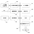
図4は、実施形態におけるデジタルビデオカメラ501における光ディスク502に格納された撮像データ(画像ファイル)のPC504に転送に関する主要ブロック構成図である。なお、デジタルビデオカメラであるから、撮像構成、AE,AF制御、並びに、符号化に関する構成を備えるが、図示ではそれらの構成については省略している点に注意されたい。以下、図4の各構成とその機能について説明する。
FIG. 4 is a main block configuration diagram regarding transfer of imaging data (image file) stored in the
メイン制御部401はバス400を介して各構成要素と接続され、メイン制御部401上で動作するソフトウェアによって各構成要素の制御指示を行う。
The
通信制御部402は、外部の機器、すなわち図5におけるPC504とUSBデバイスコネクタ410を介してUSBケーブル503で接続された場合に、先に説明したマスストレージ規格に従って通信制御を行う。
When the
入力操作制御部404は、デジタルビデオカメラ501の入力キー413に対してユーザーが入力を行った場合のキー情報を判別し、メイン制御部401上で動作するソフトウェアに対して通知を行う。
The input
また入力キー413の1つのボタンには点灯可能なLEDが埋め込まれた形式のボタン420が具備されている。このボタン420は、このデジタルビデオカメラ501が、USBケーブルでPC504に接続した際に、ダビングの開始を指示するものであると同時に、LEDの点灯の駆動制御することで、通信状況をユーザに知らせるためのものである。
In addition, one button of the
表示制御部406はデジタルビデオカメラ501の表示部412に対して表示する映像を生成し表示を制御する。
The
記録再生制御部405は、光ディスク502に対して、撮影したデータの記録、再生、また読み出したデータを内部メモリ403に転送する制御を行う。読み出されたデータは、通信制御部402を介して外部に送信するか、表示制御部412を介して表示部へ転送される。
The recording /
一方、PC504の主要部のブロック構成図を図6に示す。図示のように、装置全体の制御を司るメイン制御部(CPUで構成される)601、マウス(登録商標)等のポインティングデバイスやキーボードで構成される入力装置613からの入力を行なう入力操作制御部604、またUSBホストコネクタ610を有する通信制御部602、OSや各種アプリケーションをロードしたり、光ディスク506に書き込むためのバッファ領域として使用される内部メモリ603、CRTや液晶表示器等で構成される表示部612へのビデオ信号を出力したり、メイン制御部601からの要求に対して内部のビデオメモリへの描画する表示制御部606を備える。また、OS、及び、本実施形態における主要な処理を行なうアプリケーションプログラムを格納するハードディスクドライブ(HDD)615も備える。
On the other hand, a block diagram of the main part of the
以上、実施形態におけるデジタルビデオカメラ501及びPC504の構成について説明した。次に、実施形態における処理について説明する。
The configuration of the
<PC504におけるアプリケーションプログラムの説明>
実施形態におけるHDD615に格納されているアプリケーションプログラムは、大別して以下の3つのモジュールA乃至Cで構成される。それぞれのプログラムは次のような機能を果たす。
モジュールA:デジタルビデオカメラとのステータス通信の行うプログラム、
モジュールB:デジタルビデオカメラからの撮像画像データの受信、及び、光ディスク506への書き込み処理(ダビング処理)を行なうプログラム、
モジュールC:OSが起動した際に内部メモリ403に常駐し、ダビング処理を開始するか否かを決定するプログラム。
<Description of Application Program in
The application program stored in the
Module A: a program for status communication with a digital video camera,
Module B: a program for receiving captured image data from a digital video camera and writing processing (dubbing processing) to the
Module C: A program that resides in the
本実施形態では、上記3つのモジュールによって、デジタルビデオカメラ501をPC504にUSBケーブルで接続し、尚且つ、書き込み可能な光ディスク506が記録再生ドライブ505に装着されていることをトリガにして、自動的にデジタルビデオカメラ501の光ディスク502に記憶された全データファイル(撮像した画像ファイル)を光ディスク506に書き込む(ダビングする)。
In this embodiment, the
内部メモリ603は、本実施形態におけるアプリケーションプログラム以外にも、ユーザが利用する各種アプリケーションプログラム(例えば、文書編集やメール、WWWブラウザ等)が利用することになる。従って、デジタルビデオカメラ501をPC504に接続していない場合、本実施形態のアプリケーションの内部メモリ603に占める消費量が少ないほうが望ましい。この理由により、内部メモリ503に常駐するプログラムは、アプリケーションプログラム全てではなく、そのアプリケーションを起動するか否かを決定するモジュールCのみとした。
The
なお、実施形態のアプリケーションにとって、デジタルビデオカメラの機種名は既知である。USBインタフェースは、元々、ホットプラグアンドプレイとして策定されたインタフェースであり、USBホストコネクタ610にデジタルビデオカメラ501をUSBケーブル503を介して接続すると、マスストレージ通信の確立する。この通信確立の手順は先に説明した通りである。この際、OSは、その接続されたデバイスを認識することになり、そのデバイス名も取得する。本実施形態におけるモジュールCは、USBホストコネクタ610にデバイスが接続されたというイベント発生を監視し、USBデバイスの接続がなされた場合に実行する。以下、各モジュールA乃至Cの処理を説明する。
Note that the model name of the digital video camera is known to the application of the embodiment. The USB interface is an interface originally formulated as hot plug and play. When the
<モジュールC(常駐プログラム)の説明>
図15は、実施形態におけるモジュールCの処理手順を示すフローチャートである。この処理は、先に説明したように、USBホストコネクタ610に何らかのデバイスが接続された場合に実行するものである。
<Description of module C (resident program)>
FIG. 15 is a flowchart illustrating a processing procedure of the module C in the embodiment. This process is executed when any device is connected to the
先ず、ステップS1801では、接続されたUSBデバイスが、既知のデジタルビデオカメラ501であるか否かを判定する。否の場合には、本処理を終了する。また、デジタルビデオカメラ501が接続されたと判定した場合には、ステップS1802に進んで、記録再生ドライブ505が接続されているか否か、ステップS1803にて書き込み可能な光ディスク506がセットされているか否かを判定する。
First, in step S1801, it is determined whether the connected USB device is a known
記録再生ドライブ505が接続されていて、尚且つ、光ディスク506がセットされていると判断した場合、処理はステップS1804に進んで、デジタルビデオカメラ501に対し、PC504がダビング可能状態であることを通知するため、後述するコマンド“READY(0)”をUSBホストコネクタ610を介して送信する。次いで、ステップS1805にて、プログラムモジュールAを起動する(HDD615から内部メモリ603に読込み実行する)。
If it is determined that the recording / reproducing
また、ステップS1802、S1803のいずれかがNoであると判定した場合には、本処理を終える。 In addition, when it is determined that any of Steps S1802 and S1803 is No, this processing ends.
なお、上記はUSBホストコネクタ610にUSBデバイスが接続された場合のものであったが、記録再生ドライブ505が固定的にPC504に接続されている場合(記録再生ドライブ505が内蔵の場合)には、光ディスク506がセットされたことをトリガにして実行を開始しても良いし、両方に対応させても構わない。
The above is the case where the USB device is connected to the
<モジュールAの説明>
このモジュールAは、上記の通り、デジタルビデオカメラ501とPC504が接続され、尚且つ、書き込み可能な光ディスク506が記録再生ドライブ505にセットされている場合に実行するものである。また、このモジュールAが起動した場合、それ以前に、既にデジタルビデオカメラ501には、“READY(0)”のコマンドを送信していることになる。また、このモジュールAは一旦起動すると、ダビング中は、内部メモリ603に常駐し、デジタルビデオカメラ501からのレスポンスデータを受信した場合にも実行される。
<Description of Module A>
As described above, the module A is executed when the
本モジュールAの処理で、デジタルビデオカメラ501に送信するコマンドは図7に示すデータ構造を持つ。同コマンドは、ATAPIのコマンドブロックの構成に従った12バイトのデータで構成される。ATAPIの規格では、データオフセット0バイト目のフィールド701はこのコマンドブロックの制御情報を示しているが、本実施形態の機能はATAPIの規格で定められていないので、ベンダ固有のコマンドを示す0xFF(0xは16進数を示す)が指定する。
A command transmitted to the
フィールド702は、ATAPIの規格に従い、上位3bitにLogical Unit Numberを指定する構成としているが、本実施形態においては、0を指定する。フィールド703は、このコマンドの詳細機能を指定するもので、本実施形態においては0x01を指定する。
The
フィールド704は本実施形態において最も重要な意味を持つフィールドで、本実施形態においてはPC504のステータス情報を示しており、図9に示す値が設定される。各値の意味としては、次の通りである。
・PC504がデータを受信して記録保存が可能な状態であれば“READY(0)”、
・データを受信中であれば”転送中(1)”、
・データを受信して記録保存を行い、終了処理が実行されていれば”終了処理中(2)”、
・データを受信して記録保存が完了すれば”完了(3)”、
・データを受信して記録保存が完了するまえに処理が中断された場合には”中止(4)”、
・データを受信して記録保存が完了するまえに処理がERROR、例えば書き込みERRORが発生したことにより中断された場合には”ERROR(5)”。
A
-If the
・ If data is being received, “Transferring (1)”,
-If data is received and recorded and saved, and the end process is being executed, "End process (2)",
・ When data is received and record storage is completed, "Complete (3)"
・ If the process is interrupted before the data is received and recorded and saved, "Cancel (4)"
“ERROR (5)” when the process is interrupted by the occurrence of ERROR, for example, writing ERROR, before the data is received and the recording and saving is completed.
先に説明したように、本モジュールAが起動した際には、既に、PC504からデジタルビデオカメラ501に対して、既に“READY(0)”コマンドを送信しているので、その応答(レスポンスデータ)がデジタルビデオカメラ501から返ってくる。また、後述するように、ダビング中でも、レスポンスデータが返ってくるので、その場合にも実行することになる。かかる点にを踏まえ、モジュールAの処理を、図13のフローチャートに従って説明する。
As described above, when the module A is activated, since the “READY (0)” command has already been transmitted from the
先ず、ステップS1301では、受信したレスポンスデータのフィールド(1102)の値に従い、次にコマンドを送信する送信時間が設定される。この送信時間が設定されると、その時間を待って、モジュールAを構成するコマンド送信処理(図8)が実行される。 First, in step S1301, a transmission time for transmitting a command next is set according to the value of the field (1102) of the received response data. When this transmission time is set, the command transmission processing (FIG. 8) constituting the module A is executed after waiting for the transmission time.
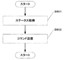
図8に示すように、このコマンド送信処理は、ステップS801で、ステータスを取得し、ステップS802にて、取得したステータスを図7に示すデータ構造のコマンドとしてデジタルビデオカメラ501に送信する。この結果、デジタルビデオカメラ501からは、そのレスポンスデータが返っているので、その都度、本処理が実行することになる。
As shown in FIG. 8, in the command transmission process, a status is acquired in step S801, and in step S802, the acquired status is transmitted to the
図13の説明に戻る。ステップS1301の処理、すなわち、コマンド送信の起動タイミングの設定を行なうと、処理はステップS1302に進んで、レスポンスデータのフィールド(後述する図11のフィールド1105)を確認し、“READY(0)”であれば、デジタルビデオカメラ501は、撮像した画像データの送信が可能状態であるものとし、ステップS1303に遷移する。
Returning to the description of FIG. When the process of step S1301, that is, the command transmission start timing is set, the process proceeds to step S1302, the response data field (
ステップS1303では、レスポンスデータのフィールド(後述する図11のフィールド1104)を確認し、“1”が設定されているか否かを判断する。詳細は後述するが、このフィールドが“1”にセットされるのは、デジタルビデオカメラ501におけるダビング開始を指示するボタンが押下された場合である。フィールド1104が“1”にセットされている場合、ステップS1304に進み、デジタルビデオカメラ501の光ディスク502に記録されているデータの読み出し、大容量光ディスク506への書き込み(ダビング)を行なうモジュールBを起動し(HDD615から内部メモリ603へロードし、実行する)、処理を終了する。
In step S1303, the response data field (
一方、ステップS1302で、レスポンスデータのフィールド1105のステータスが“READY(0)”以外であれば、ステップS1305に進み、モジュールBが起動されているか否かを判断し、モジュールBが起動されている場合には、ステップS1306でそのステータスをモジュールBに通知し、本処理を終える。
On the other hand, if the status of the
なお、説明が前後するが、PC504上で動作するOSは、マルチタスクのOSであり、モジュールAとBとは別タスクとして動作する。
Although the description will be mixed, the OS operating on the
<モジュールBの説明>
次に、モジュールBの処理を図14のフローチャートに従って説明する。
<Description of Module B>
Next, the process of module B will be described with reference to the flowchart of FIG.
ステップS1401では、データの取得コマンドをデジタルビデオカメラ501に対して送信する。ここで、データの取得コマンドは、前記ATAPIの規格に従って、図3のREAD(10)コマンドとして構成され、マスストレージの通信方式によって送信される。
In step S1401, a data acquisition command is transmitted to the
ステップS1402では、デジタルビデオカメラ501からのレスポンスを通信制御部602を介して受信する。
In step S1402, a response from the
ステップS1403では、受信したデータがエラーかどうか判別し、エラーであればステップS1409に遷移しエラーメッセージを表示部612に表示し処理を終了する。エラーでなければステップS1404に遷移する。
In step S1403, it is determined whether the received data is an error. If there is an error, the process proceeds to step S1409, an error message is displayed on the
ステップS1404では、データの受信を行い、その受信したデータの書き込みを記録再生ドライブ605に指示し、光ディスク506への書き込みを行なう。
In step S1404, data is received, and the recording / reproduction drive 605 is instructed to write the received data, and writing to the
ステップS1405では、書き込みエラーが発生した場合には、ステップS1409に遷移し、エラーメッセージを表示部612に表示し処理を終了する。エラーが無ければステップ1406に遷移する。
In step S1405, if a write error has occurred, the process proceeds to step S1409, an error message is displayed on the
ステップS1406では、ユーザーによる書き込みキャンセルの指示が入力装置613で入力されたのか否かを判断し、もしその指示があった場合にはステップS1409に遷移しエラーメッセージを表示部612に表示し処理を終了する。なお、実施形態におけるダビング処理は、見かけ上、PC504のバックグランドの処理として実行しているが、モジュールBが起動した場合には、OSが備えるタスクバーに、そのアイコンを表示させ、そのアイコンが指示された場合に、メニューを表示し、その中からダビングのキャンセルが指示できるようにした。
In step S1406, it is determined whether or not an instruction to cancel writing by the user is input from the
ステップS1406にて、キャンセル指示がないと判断した場合には、ステップS1407に遷移し、デジタルビデオカメラ501とPC504のUSB接続が接続されていることを、通信制御部602において確認し、接続されていないことを検出したら、ステップ1409に遷移しエラーメッセージを表示部612に表示し処理を終了する。接続されていれば、ステップS1408に遷移する。
If it is determined in step S1406 that there is no cancel instruction, the process proceeds to step S1407, and the
ステップS1408では、ソフトウェアモジュールAから中止要求があるか否かの通知を確認し、中止要求がある場合には、ステップS1409に遷移しエラーメッセージを表示部612に表示し処理を終了する。
In step S1408, it is confirmed whether or not there is a cancel request from the software module A. If there is a cancel request, the process proceeds to step S1409, an error message is displayed on the
ここで、本実施形態では、ソフトウェアモジュールAからソフトウェアモジュールBの通知は内部メモリ603上に確保した状態フラグによって行う。この場合の状態フラグがとりうる値は、図12の値に従い、”LOW BATTERY”(3)、”MODE CHANGE”(4)、”NO DISC”(5)、”NO READABLE DISC”(6)が設定されている場合には中止要求があるものとする。中止要求がなければ、ステップS1410に遷移する。
Here, in this embodiment, the notification from the software module A to the software module B is performed by a status flag secured on the
ステップS1410では、デジタルビデオカメラ501の光ディスク502に記録されたすべてのデータの読み取りが完了したかどうかを判別する。この判別はマスストレージ通信において、記録容量が判別できるので、その情報を利用する。全てのデータを取得していなければ、再度ステップS1401に遷移し、処理を継続する。
In step S1410, it is determined whether reading of all data recorded on the
また、ステップS1410において、全てのデータ取得が完了していると判断された場合には、ステップS1411に進み、モジュールBは勿論、モジュールAを終了する(OSに対して、モジュールA,Bの終了を通知し、内部メモリ603からそれらプログラムを開放させる)。 If it is determined in step S1410 that all data acquisition has been completed, the process proceeds to step S1411, and module A is ended as well as module B (the end of modules A and B with respect to the OS). And the programs are released from the internal memory 603).
なお、ソフトウェアモジュールBは図14のフローを実行中に、ソフトウェアモジュールAに対して、情報の通知を状態に応じて行っている。ソフトウェアモジュールBからソフトウェアモジュールAの通知は、前述と同様に内部メモリ603上に配置された状態フラグによって行い、とりうる値は図9の値に従う。従って、ダビング中にも、図8に示す処理が実行されることになる。
The software module B notifies the software module A of information according to the state during the execution of the flow of FIG. The notification from the software module B to the software module A is performed by the status flag arranged on the
図16は、ソフトウェアモジュールAとソフトウェアモジュールBが内部メモリ603上に配置された状態フラグを介して通知を行う状態を示している。
FIG. 16 shows a state in which software module A and software module B perform notification via a status flag arranged on
ソフトウェアモジュールA1601からソフトウェアモジュールB1602への通知は内部メモリ603内に確保された状態フラグ1604を介して行われる。一方、ソフトウェアモジュールB1602からソフトウェアモジュールA1601への通知は、状態フラグ1603を介して行われることを示している。
Notification from the
ソフトウェアモジュールBからソフトウェアモジュールAに対して通知を行うタイミングは、図14のフローチャートを参照すると次の通りである。 The timing of notification from the software module B to the software module A is as follows with reference to the flowchart of FIG.
ステップS1401:“転送中”(1)が通知される。 Step S1401: “Transferring” (1) is notified.
ステップS1409:ステップS1403、あるいはステップS1405から遷移してきた場合には”ERROR”(5)を通知し、ステップS1406)から遷移してきた場合には、”中止”(5)が通知される。 Step S1409: “ERROR” (5) is notified when transitioning from step S1403 or step S1405, and “stop” (5) is notified when transitioning from step S1406).
従って、図8のステップS801における処理は、状態フラグ1603からステータスを取得し、デジタルビデオカメラ501に送信することになる。
Accordingly, the processing in step S801 in FIG. 8 acquires the status from the status flag 1603 and transmits it to the
以上が、本実施形態におけるPC504におけるアプリケーションプログラム(モジュールA、B,C)の処理の説明である。
The above is the description of the processing of the application program (modules A, B, and C) in the
<デジタルビデオカメラ501の処理の説明>
次に、実施形態におけるデジタルビデオカメラ501における処理について説明する。
<Description of Processing of
Next, processing in the
実施形態におけるデジタルビデオカメラ501は、通常のUSBインタフェースを備えるデジタルビデオカメラと同様、PCに接続された場合には、マスストレージクラスデバイスとして遷移する。そして、PC上の動作する実施形態のアプリケーションプログラムは、マスストレージクラスプロトコルを使って、そのデバイスから全ファイルを読込み、光ディスクPC506に書き込むを行なう。
The
図10に示すフローチャートは、デジタルビデオカメラ501がUSBケーブル503でPC504と接続され、通信が確立している状態での、メイン制御部401が通信制御部402からの通知に応じた処理である。
The flowchart shown in FIG. 10 is a process in which the
ステップS1001において、メイン制御部401は、通信制御部402を介してPC504からのコマンドを受信したと判断したか、或いは、USBケーブルが切断(コネクタからUSBケーブルが外れた場合等)したかを判定する。USBケーブル切断であると判断した場合には、ステップS1003に進んで、ボタン420のLEDを消燈する。
In step S1001, the
また、コマンドを受信したと判断した場合には、メイン制御部401は、そのコマンドの判別が行われる。ここで、図7のコマンドと判別された場合には、ステップS1002に遷移するが、別のコマンドであった場合には、そのコマンドに応じた処理を実施する。本実施形態には、説明簡単化のため上記以外のコマンド処理については省略する。
If it is determined that a command has been received, the
ステップS1002において、図7のコマンドのStatusフィールド704の値がPC504が受信データを記録可能な状態を示すREADY(0)であれば、ステップS1004に処理を進める。また、それ以外であれば、ステップS1005に進む。
In step S1002, if the value in the
READY(0)コマンドを受信した場合、つまり、PC504はダビングが可能であることを通知してきたことになる。そこで、ステップS1004では、記録再生制御部405に光ディスク502がセットされているか否か、かつ、セットされている場合には、その光ディスク502に撮影した映像データが記録されているか否かを判断する。このとき、デジタルビデオカメラ501が電源が適切な状態であるか、適正なモードになっているか否かの判別も合わせておこなう。
When the READY (0) command is received, that is, the
例えば、USBインタフェースの転送帯域(USB.ver 2.0のHigh Speed モード)は480Mbpsと十分に高速なので、必然、光ディスク502は、通常の撮影時と比較して高速に回転させて読出し、PC504に転送することになる。従って、撮影モードになっている場合には、PC504へのダビングはできない。上記適正なモードとは、光ディスク502に対するアクセスがないようなモードである。
For example, the transfer bandwidth of the USB interface (USB.ver 2.0 High Speed mode) is sufficiently high at 480 Mbps, so the
さて、デジタルビデオカメラ405に記録済み光ディスク502が挿入されており、かつ低電圧(ローバッテリー)状態でなく、モードも適切であると判別された場合には、ステップS1006に処理を進め、操作者に、ダビング開始可能であることを知らせるため、ボタン420のLEDを点灯させる。そして、ステップS1009で、PC504からのコマンド(図7)に対するレスポンスデータをステップS1005にて生成する。ここで、生成するレスポンスデータは図11に示される8バイトの構成をとる。
If it is determined that the recorded
以下に図11の応答データの構造について説明する。 The structure of the response data in FIG. 11 will be described below.
最初の2バイトのフィールド1101は、応答データ長を格納するもので、本実施形態においては8バイトを設定する。
The first 2-
フィールド1102は、PC504が次のコマンドを送信までの時間を100ms単位で指定するものである。つまり、フィールド1102の値を、例えば1としておくと、PC504が次にコマンドを送ってくるのは100ms後とすることができる。
A
フィールド1103は、図7のコマンドでフィールド703に設定された値をそのまま設定する。本実施形態においては0x01を指定する。
In the
フィールド1104のDTは、デジタルビデオカメラ501において、ユーザーがダビング指示ボタン420が押されたか否かを示すフラグで、ボタン420が押されたら1を設定する。ボタン420の押下の検出は、図17のフローにおいて実現されるが後述する。
DT in the
フィールド1105は、デジタルビデオカメラ501のステータスを示すもので値としては、図12の表に示される値をとる。各値の意味としては、次の通りである。
・デジタルビデオカメラ501がデータを送信可能な状態であれば”READY”(0)、
・データを送信中であれば”転送中”(1)
・デジタルビデオカメラ501が別の処理を実行しており、PC504からのコマンド要求に応答できない場合には”BUSY”(2)、
・データを送信中にバッテリ電圧が低くなった場合”LOW BATTERY”(3)、
・データをデジタルビデオカメラ501のモードが変更された場合には”MODE CHANGE”(4)、
・デジタルビデオカメラ501に光ディスク502が挿入されていない場合には”NO DISC”(5)、
・デジタルビデオカメラ502に読み込み可能な光ディスク502が挿入されていない場合には”NO READABLE DISC”(6)
図10のフローチャートに戻り、ステップS1009において生成されるレスポンスデータのフィールド1105には、デジタルビデオカメラ501がデータを送信可能な状態を示す”READY”(0)が設定される。また、このとき、後述する図17の処理においうて、フィールド1104のDTに“1”がセットされていた場合(ユーザがダビングボタン420を押下した場合)には、それも合わせて生成することになる。
A
If the
・ "Transferring" if data is being transmitted (1)
If the
・ When battery voltage becomes low during data transmission, “LOW BATTERY” (3),
・ When the mode of the
“NO DISC” (5) when the
If the readable
Returning to the flowchart of FIG. 10, “READY” (0) indicating that the
一方、ステップS1005において、PC504からのコマンドのStatusフィールド704が”転送中(1)”であった場合には、ステップS1013に進んで、光ディスク502が正常に挿入されているか、デジタルビデオカメラ501が低電状態でなく、かつ、モードが正しいかの判別を行う。これらが正常であれば、ステップS1008に遷移し、ボタン420のLEDの点滅させ、操作者に転送中であることを報知する。その後、ステップS1011において、レスポンスデータを生成するが、このときのStatusフィールド1105には、同様に図13に示される“転送中(1)”が設定される。また、フィールド1104は、データ転送中なので、DTビット=1が設定される。
On the other hand, if the
またステップS1005において、受信コマンドのStatusフィールド704が、”転送中(1)”でないと判断した場合には、ステップS1007に処理を進める。このステップS1007では、ボタン420のLEDの消燈を実行する。
If it is determined in step S1005 that the
ステップS1010においては、ステップS1004から遷移してきた場合には、デジタルビデオカメラ501がデータを送信可能な状態ではないので、生成されるレスポンスデータのフィールド1105には、“NO DISC(5)”か、“NO READABLE DISC(6)”が設定される。また、フィールド1104は、データ転送中ではないので、DTビット=0が設定される。
In step S1010, since the
以上生成されたレスポンスデータは、ステップS1012において、通信制御部402を介してPC504に送信される。
The response data generated above is transmitted to the
なお、上記レスポンスデータを送信した場合、そのレスポンスデータは次回に送信するまで、内部メモリ403内に保持しておくものとする。つまり、レスポンスデータは、前回のレスポンスデータを更新することで生成するものである。
When the response data is transmitted, the response data is retained in the
次に、実施形態におけるデジタルビデオカメラ501における、ユーザー入力処理を検出するための処理を図17のフローチャートに従って説明する。この処理は、図10の処理と非同期に実行されるものである。この処理は、メイン制御部401が実行するソフトウェアによって行われるが、ユーザーへのレスポンスを高速に行いたいのであれば、ハードウェア割り込みで実現されても良い。
Next, a process for detecting a user input process in the
入力キー413のいずれかのボタンが押下されると、この処理が開始される。
When any button of the
先ず、ステップS1701では、押下されたボタンがダビングボタン420であるか否かを判断する。否であれば本処理を終え、ダビングボタン420が押下された場合、ステップS1702に進み、内部メモリ403に保持されている最新のレスポンスデータのステータスを調べ、“転送中”となっているか否かを判断する。“転送中”である場合には、既に画像データの転送が行われていることを意味するので、この処理を終了する。
First, in step S1701, it is determined whether the pressed button is the
また、転送中ではないと判断した場合には、ステップS1703に進み、レスポンスデータのステータスはREADY状態であるか否かを判断する。READY状態である場合、デジタルビデオカメラ501、及び、PC504が、ダビング条件た整っていて、ユーザのダビング指示を待っている状態であることを意味するので、処理はステップS1704に進んで、内部メモリ403のレスポンスデータのフィールド1104のDTに“1”をセットする。
If it is determined that the data is not being transferred, the process advances to step S1703 to determine whether the status of the response data is READY. In the READY state, it means that the
この結果、先の図10の処理で、次回、PC504からコマンドを受信した場合に、図10のステップS1009でフィールド1104のDTが“1”をセットしたレスポンスデータが生成され、PCにダビング指示がなされたことを通知することが可能になる。
As a result, when a command is received from the
なお、PC504からデジタルビデオカメラ501内の画像データファイルの取得は、先に説明したように、実施形態におけるデジタルビデオカメラをマスストレージとして処理することになるので、別タスクで行われる。マスストレージクラスの伝送は、PC504から見た場合に、デジタルビデオカメラ501を外部記憶装置として読み出すものであり、USB接続の外部記憶装置と同様であるので、その説明は省略する。
The acquisition of the image data file in the
注意したい点は、PCが外部記憶装置からファイルを取得する場合、1つ1つのファイルを指定して読出す処理を行なうものであるので、外部記憶装置は、自身が保持する全データを転送したか否かを判別することはできない。これはデジタルビデオカメラ501にも言えることである。かかる点、実施形態によれば、取得中(転送中)か否か、転送が完了したか否かを含むほぼ全てのステータスをPC504側で生成し、それをデジタルビデオカメラ501に通知し、ダビングボタン420の点灯の制御に使うことになる。従って、ユーザから見ると、あたかもデジタルビデオカメラ501が自主的にPC504に画像ファイルを転送しているかのように振る舞うことことになる。
The point to note is that when the PC acquires a file from the external storage device, it performs the process of designating and reading each file, so the external storage device transferred all the data held by itself. It is not possible to determine whether or not. This is also true for the
以上実施形態について説明したが、まとめると、次のようになる。
1).デジタルビデオカメラ501と、PC504にUSBケーブル503で接続し、尚且つ、PC504に書き込み可能な記録媒体である光ディスク506がセットされている場合、PC504はデジタルビデオカメラ501に対してダビング可能であることを示すREADYコマンドを発行する。これ以降、PC504は、デジタルビデオカメラ501からのレスポンスに対してステータスを返すことになる。
2).デジタルビデオカメラ501は、PC504からコマンドを受信する毎に、そのレスポンスを生成し、PC504に通知する。デジタルビデオカメラ501が、PC504よりREADYコマンドを受信した場合には、画像ファイルが格納されている記録媒体である光りディスク502がセットされている場合、READYレスポンスをPC504に返す。PC504からREADYコマンドを受信したことを受けて、ダビングボタン420のLEDを点灯させ、ユーザにそのボタンの押下によりダビングが開始されることを報知する。
3).互いにREADYコマンド、レスポンスを送受信を行なっている最中に、デジタルビデオカメラ501のダビングボタン420を押下すると、次回のレスポンスデータで、ダビングボタン420が押下された旨をPC504に通知する。
4).PC504は、レスポンスデータを調べて、ダビングボタンの押下がなされたことを検知すると、ダビングを開始する。このとき、デジタルビデオカメラ501には、テンソウ中であることを示すコマンドを発行する。
5).デジタルビデオカメラ501は、このコマンドを受けると、ダビングボタン420のLEDを点滅させ、画像ファイルの転送中であることをユーザに通知する。尚且つ、受信したコマンドに対応するレスポンスをPC504に返す。
6.PC504は全データファイルの受信が完了し、光ディスク506への書き込みが完了すると、完了した旨のコマンドをデジタルビデオカメラ501に通知する。
7.デジタルビデオカメラ501は、このコマンドを受信すると、ダビングボタン420を消燈する。
Although the embodiment has been described above, it is summarized as follows.
1). When the
2). Each time the
3). When the
4). When the
5). Upon receiving this command, the
6). When the
7). When the
以上である。上記のように、デジタルビデオカメラ501におけるダビングボタン420のLEDの発光制御を、PC504からのステータスに応じて制御することで、PCのマスストレージとして機能しながらも、あたかも、デジタルビデオカメラ501が自主的にPC504に画像ファイルの転送を行い、その間の状態を報知しているかのようにすることが可能になる。
That's it. As described above, by controlling the light emission control of the LED of the
なお、デジタルビデオカメラ501が、PC504からの“完了”コマンドを受信した場合、全ファイルのダビングが成功したことを意味するので、光ディスク502を初期化するようにしても構わない。この初期化は、PC504側で行なうと都合が良い。すなわち、PC504にとってデジタルビデオカメラ501は、マスストレージクラスデバイスとして認識されるので、通常のフレキシブルディスクと同様の扱いが可能であり、デジタルビデオカメラ501の記憶媒体をPC504で初期化するプログラムを実行するだけで良い。このようにすると、デジタルビデオカメラ501側のファームウェアを格納するメモリは少なくて済む。
Note that when the
また、実施形態ではデジタルビデオカメラ501とPC504とがUSBインタフェースを介して接続する例を説明したが、デジタルビデオカメラ501をマスストレージクラスデバイスとして認識し、マスストレージデバイスプロトコルを用いてファイルを読込むことが可能であれば、IEEE1394インタフェース、或いは、ネットワークインタフェースを介して接続する場合に適用しても良い。
In the embodiment, the
また、実施形態では、ダビングボタン420がLEDを内蔵しているものとしたが、LEDとボタンは一体でなくても構わない。ただし、ダビング可能になった場合に、ユーザに対してどのボタンを押下すれば良いのかを知らせるためには、上記のように一体であることが望ましい。
In the embodiment, the
また、上記実施形態の説明からもわかるように、PC504における処理の特徴は、アプリケーションプログラムによるものであるので、本発明はコンピュータプログラムをその範疇とするのは明らかである。また、実施形態におけるPC504のアプリケーションプログラムは、デジタルビデオカメラ501に添付するCDROM等にバンドルされることになる。そして、このCDROM(コンピュータ可読記憶媒体)を、PCにセットして、システムにコピーもしくはインストールすることで、上記実施形態におけるアプリケーションプログラムが実行可能になるわけであるから、当然、そのようなコンピュータ可読記憶媒体も本発明の範疇にある。
Further, as can be seen from the description of the above embodiment, since the processing feature of the
Claims (10)
前記通信手段を介して外部装置の接続を検知したらマスストレージクラスプロトコルに従ったマスストレージ通信を確立し、接続された外部装置のデバイス名を検出する検出手段と、
前記記録手段に書き込み可能な記憶媒体がセットされているか否かを判定する判定手段と、
前記検出手段で検出した外部装置のデバイス名が、ダビングする対象の撮像装置のものであり、且つ、前記判定手段が、書き込み可能な記憶媒体が前記記録手段にセットされていると判定した場合、前記撮像装置の前記表示部が前記指示部への指示をユーザに促す表示状態とするためのデータを含むステータスコマンドを前記通信手段を介して前記撮像装置に送信するダビング初期処理手段と、
該ダビング初期処理手段でステータスコマンドを送信した後、前記通信手段を介して前記撮像装置からのレスポンスコマンドを受信する毎に、前記撮像装置の前記表示部がダビングの進捗状況を表わす表示状態となるためのステータスコマンドを前記撮像装置に送信するダビング中間処理手段とを備え、
前記ダビング中間処理手段は、
前記レスポンスコマンド中に、前記指示部が指示されたことを示す情報が含まれている場合、前記撮像装置をマスストレージデバイスとして認識し、当該マスストレージデバイス内の全データファイルの読出し、及び、読出した全データファイルの前記記録手段を制御しての前記記憶媒体への書き込みのダビング処理を開始するダビング手段と、
該ダビング手段よるダビング処理中に受信した前記レスポンスコマンドに対しては、転送中を示すデータを含むステータスコマンドを前記通信手段を介して前記撮像装置に送信する手段と、
前記ダビング手段よるダビング処理が完了した以降に受信したレスポンスコマンドに対しては、ダビング完了を示すデータを含むステータスコマンドを前記通信手段を介して前記撮像装置に送信する手段とを備える
ことを特徴とする情報処理装置。 A communication unit that communicates with an imaging device having an instruction unit that instructs the start of dubbing and a display unit that displays the progress of the dubbing; and a recording unit that writes data to a predetermined writable storage medium. An information processing apparatus for performing a dubbing process by acquiring a data file stored and held in the imaging apparatus via a means and writing the acquired data file to the storage medium by controlling the recording means;
When detecting connection of an external device via the communication means, the mass storage communication according to the mass storage class protocol is established, and detection means for detecting the device name of the connected external device;
Determining means for determining whether a writable storage medium is set in the recording means;
If the device name of the external device detected by the detection means, are of the imaging apparatus of the subject to be dubbed, the and, the determining means determines that the writable storage medium is set in the recording means, A dubbing initial processing means for transmitting a status command including data for causing the display unit of the imaging apparatus to enter a display state that prompts a user to instruct the instruction unit to the imaging apparatus via the communication unit;
After the status command is transmitted by the dubbing initial processing means, every time a response command is received from the imaging apparatus via the communication means, the display unit of the imaging apparatus is in a display state indicating the dubbing progress status. and a dubbing intermediate processing means for transmitting a status command for the imaging device,
The dubbing intermediate processing means is
When the response command includes information indicating that the instruction unit has been instructed , the imaging device is recognized as a mass storage device, and all data files in the mass storage device are read and read. Dubbing means for starting the dubbing process of writing to the storage medium by controlling the recording means of all the data files;
For the response command received during the dubbing process by the dubbing means, means for transmitting a status command including data indicating that the data is being transferred to the imaging device via the communication means;
In response to a response command received after the dubbing process by the dubbing unit is completed, a status command including data indicating completion of dubbing is transmitted to the imaging apparatus via the communication unit. Information processing apparatus.
前記通信手段を介して外部装置の接続を検知したらマスストレージクラスプロトコルに従ったマスストレージ通信を確立し、接続された外部装置のデバイス名を検出する検出工程と、
前記記録手段に書き込み可能な記憶媒体がセットされているか否かを判定する判定工程と、
前記検出工程で検出した外部装置のデバイス名が、ダビングする対象の撮像装置のものであり、且つ、前記判定工程で、書き込み可能な記憶媒体が前記記録手段にセットされていると判定された場合、前記撮像装置の前記表示部が前記指示部への指示をユーザに促す表示状態とするためのデータを含むステータスコマンドを前記通信手段を介して前記撮像装置に送信するダビング初期処理工程と、
該ダビング初期処理工程でステータスコマンドを送信した後、前記通信手段を介して前記撮像装置からのレスポンスコマンドを受信する毎に、前記撮像装置の前記表示部がダビングの進捗状況を表わす表示状態となるためのステータスコマンドを前記撮像装置に送信するダビング中間処理工程とを備え、
前記ダビング中間処理工程は、
前記レスポンスコマンド中に、前記指示部が指示されたことを示す情報が含まれている場合、前記撮像装置をマスストレージデバイスとして認識し、当該マスストレージデバイス内の全データファイルの読出し、及び、読出した全データファイルの前記記録手段を制御しての前記記憶媒体への書き込みのダビング処理を開始するダビング工程と、
該ダビング工程よるダビング処理中に受信した前記レスポンスコマンドに対しては、転送中を示すデータを含むステータスコマンドを前記通信手段を介して前記撮像装置に送信する工程と、
前記ダビング工程よるダビング処理が完了した以降に受信したレスポンスコマンドに対しては、ダビング完了を示すデータを含むステータスコマンドを前記通信手段を介して前記撮像装置に送信する工程とを備える
ことを特徴とする情報処理装置の制御方法。 A communication unit that communicates with an imaging device having an instruction unit that instructs the start of dubbing and a display unit that displays the progress of the dubbing; and a recording unit that writes data to a predetermined writable storage medium. A method for controlling an information processing apparatus that obtains a data file stored and held in the imaging apparatus via a means and performs a dubbing process by controlling the recording means and writing the obtained data file to the storage medium. ,
A detection step of establishing mass storage communication according to the mass storage class protocol when detecting connection of an external device via the communication means, and detecting a device name of the connected external device;
A determination step of determining whether a writable storage medium is set in the recording means;
If the device name of the external device detected by the detecting step are those of the imaging apparatus of the subject to be dubbed, which and, in the determining step, it is judged writable storage medium is set in the recording means A dubbing initial processing step of transmitting a status command including data for causing the display unit of the imaging device to enter a display state that prompts the user to instruct the instruction unit to the imaging device via the communication unit;
After the status command is transmitted in the dubbing initial processing step, every time a response command is received from the imaging device via the communication means, the display unit of the imaging device is in a display state indicating the dubbing progress status. and a dubbing intermediate processing step of transmitting the status command to the imaging device,
The dubbing intermediate processing step includes
When the response command includes information indicating that the instruction unit has been instructed , the imaging device is recognized as a mass storage device, and all data files in the mass storage device are read and read. A dubbing step of starting a dubbing process of writing to the storage medium by controlling the recording means of all the data files;
In response to the response command received during the dubbing process by the dubbing process, a process of transmitting a status command including data indicating that transfer is in progress to the imaging apparatus via the communication unit;
For a response command received after the dubbing process by the dubbing process is completed, a step of transmitting a status command including data indicating completion of dubbing to the imaging apparatus via the communication unit is provided. Control method for information processing apparatus.
前記コンピュータを、
前記通信手段を介して外部装置の接続を検知したらマスストレージクラスプロトコルに従ったマスストレージ通信を確立し、接続された外部装置のデバイス名を検出する検出手段と、
前記記録手段に書き込み可能な記憶媒体がセットされているか否かを判定する判定手段と、
前記検出手段で検出した外部装置のデバイス名が、ダビングする対象の撮像装置のものであり、且つ、前記判定手段が、書き込み可能な記憶媒体が前記記録手段にセットされていると判定した場合、前記撮像装置の前記表示部が前記指示部への指示をユーザに促す表示状態とするためのデータを含むステータスコマンドを前記通信手段を介して前記撮像装置に送信するダビング初期処理手段と、
該ダビング初期処理手段でステータスコマンドを送信した後、前記通信手段を介して前記撮像装置からのレスポンスコマンドを受信する毎に、前記撮像装置の前記表示部がダビングの進捗状況を表わす表示状態となるためのステータスコマンドを前記撮像装置に送信するダビング中間処理手段とを備え、
前記ダビング中間処理手段は、
前記レスポンスコマンド中に、前記指示部が指示されたことを示す情報が含まれている場合、前記撮像装置をマスストレージデバイスとして認識し、当該マスストレージデバイス内の全データファイルの読出し、及び、読出した全データファイルの前記記録手段を制御しての前記記憶媒体への書き込みのダビング処理を開始するダビング手段と、
該ダビング手段よるダビング処理中に受信した前記レスポンスコマンドに対しては、転送中を示すデータを含むステータスコマンドを前記通信手段を介して前記撮像装置に送信する手段と、
前記ダビング手段よるダビング処理が完了した以降に受信したレスポンスコマンドに対しては、ダビング完了を示すデータを含むステータスコマンドを前記通信手段を介して前記撮像装置に送信する手段として機能させる
ことを特徴とするコンピュータプログラム。 A computer comprising a communication unit that communicates with an imaging device having an instruction unit for instructing the start of dubbing and a display unit that displays the progress of the dubbing, and a recording unit that writes data to a predetermined writable storage medium By reading and executing, the computer obtains a data file stored and held in the imaging apparatus via the communication unit, and controls the recording unit to write the acquired data file to the storage medium. A computer program that functions as an information processing device that performs processing,
The computer,
When detecting connection of an external device via the communication means, the mass storage communication according to the mass storage class protocol is established, and detection means for detecting the device name of the connected external device;
Determining means for determining whether a writable storage medium is set in the recording means;
If the device name of the external device detected by the detection means, are of the imaging apparatus of the subject to be dubbed, the and, the determining means determines that the writable storage medium is set in the recording means, A dubbing initial processing means for transmitting a status command including data for causing the display unit of the imaging apparatus to enter a display state that prompts a user to instruct the instruction unit to the imaging apparatus via the communication unit;
After the status command is transmitted by the dubbing initial processing means, every time a response command is received from the imaging apparatus via the communication means, the display unit of the imaging apparatus is in a display state indicating the dubbing progress status. and a dubbing intermediate processing means for transmitting a status command for the imaging device,
The dubbing intermediate processing means is
When the response command includes information indicating that the instruction unit has been instructed , the imaging device is recognized as a mass storage device, and all data files in the mass storage device are read and read. Dubbing means for starting the dubbing process of writing to the storage medium by controlling the recording means of all the data files;
For the response command received during the dubbing process by the dubbing means, means for transmitting a status command including data indicating that the data is being transferred to the imaging device via the communication means;
In response to a response command received after the dubbing process by the dubbing unit is completed, a status command including data indicating dubbing completion is functioned as a unit that transmits to the imaging device via the communication unit. Computer program.
前記通信手段を介して外部装置の接続を検知した場合、マスストレージクラスプロトコルに従ったマスストレージ通信を確立して、接続された外部装置に対してデバイス名を通知すると共に、前記記憶手段を前記外部装置にとってのマスストレージクラスデバイスとして機能させる機能遷移手段と、
該機能遷移手段でマスストレージクラスデバイスとして遷移した後、前記通信手段を介して、前記外部装置よりステータスコマンドを受信した場合、前記撮像装置の状態をレスポンスデータとして生成し、前記通信手段を介して前記外部装置に送信するレスポンスデータ送信手段と、
受信したステータスコマンドがダビング可、ダビング中、ダビング完了のいずれを示すかに応じて前記表示部の表示状態を変更する表示制御手段とを備え、
前記レスポンスデータ送信手段は、
前記指示部によるダビング開始指示がなされた場合、前記外部装置がダビング処理を開始するため、前記指示部が指示されたことを示すレスポンスデータを生成し、前記通信手段を介して前記外部装置に送信する
ことを特徴とする撮像装置。 Imaging means, storage means for storing a data file obtained by imaging, communication means for communicating with an external device, an instruction unit for instructing start of dubbing of the data file stored in the storage means, and the dubbing An imaging device comprising a display unit for displaying the progress status of
When connection of an external device is detected via the communication means, mass storage communication according to a mass storage class protocol is established, a device name is notified to the connected external device, and the storage means is Function transition means for functioning as a mass storage class device for external devices,
After the transition as the mass storage class device by the function transition means, when a status command is received from the external device via the communication means, the state of the imaging device is generated as response data, and the communication means via the communication means Response data transmitting means for transmitting to the external device;
Display control means for changing the display state of the display unit depending on whether the received status command indicates dubbing is possible, dubbing is in progress, or dubbing is completed ,
The response data transmission means includes
When a dubbing start instruction is given by the instruction unit, the external device starts dubbing processing, so that response data indicating that the instruction unit has been instructed is generated and transmitted to the external device via the communication unit An imaging apparatus characterized by:
該ローバッテリー検出手段でローバッテリー状態を検出した場合、前記レスポンスデータにローバッテリー状態を示す情報を含ませる手段と
を備えることを特徴とする請求項6に記載の撮像装置。 Furthermore, a low battery detection means for detecting a low battery state,
The imaging apparatus according to claim 6 , further comprising: a unit that includes information indicating a low battery state in the response data when the low battery state is detected by the low battery detection unit.
前記通信手段を介して外部装置の接続を検知した場合、マスストレージクラスプロトコルに従ったマスストレージ通信を確立して、接続された外部装置に対してデバイス名を通知すると共に、前記記憶手段を前記外部装置にとってのマスストレージクラスデバイスとして機能させる機能遷移工程と、
該機能遷移工程によってマスストレージクラスデバイスとして遷移した後、前記通信手段を介して、前記外部装置よりステータスコマンドを受信した場合、前記撮像装置の状態をレスポンスデータとして生成し、前記通信手段を介して前記外部装置に送信するレスポンスデータ送信工程と、
受信したステータスコマンドがダビング可、ダビング中、ダビング完了のいずれを示すかに応じて前記表示部の表示状態を変更する表示制御工程とを備え、
前記レスポンスデータ送信工程は、
前記指示部によるダビング開始指示がなされた場合、前記外部装置がダビング処理を開始するため、前記指示部が指示されたことを示すレスポンスデータを生成し、前記通信手段を介して前記外部装置に送信する
ことを特徴とする撮像装置の制御方法。 Imaging means, storage means for storing a data file obtained by imaging, communication means for communicating with an external device, an instruction unit for instructing start of dubbing of the data file stored in the storage means, and the dubbing And a display unit for displaying the progress status of the imaging apparatus,
When connection of an external device is detected via the communication means, mass storage communication according to a mass storage class protocol is established, a device name is notified to the connected external device, and the storage means is Function transition process to function as a mass storage class device for external devices,
After a transition as a mass storage class device by the function transition step, when a status command is received from the external device via the communication unit, the state of the imaging device is generated as response data, and the communication unit A response data transmission step for transmitting to the external device;
A display control step of changing a display state of the display unit according to whether the received status command indicates dubbing is possible, dubbing is in progress, or dubbing is completed ,
The response data transmission step includes
When a dubbing start instruction is given by the instruction unit, the external device starts dubbing processing, so that response data indicating that the instruction unit has been instructed is generated and transmitted to the external device via the communication unit An image pickup apparatus control method characterized by:
当該撮像装置に記憶保持されたデータファイルを読出し、所定の記憶媒体にダビングする情報処理装置とで構成されるデータ伝送システムであって、
前記情報処理装置は、
前記外部装置と通信する第2の通信手段と、
所定の書き込み可能な記憶媒体にデータを書き込む記録手段と、
前記第2の通信手段を介して外部装置の接続を検知したらマスストレージクラスプロトコルに従ったマスストレージ通信を確立し、接続された外部装置のデバイス名を検出する検出手段と、
前記記録手段に書き込み可能な記憶媒体がセットされているか否かを判定する判定手段と、
前記検出手段で検出した外部装置のデバイス名が、ダビングする対象の前記撮像装置のものであり、且つ、前記判定手段が、書き込み可能な記憶媒体が前記記録手段にセットされていると判定した場合、前記撮像装置の前記表示部が前記指示部への指示をユーザに促す表示状態とするためのデータを含むステータスコマンドを前記第2の通信手段を介して前記撮像装置に送信するダビング初期処理手段と、
該ダビング初期処理手段でステータスコマンドを送信した後、前記第2の通信手段を介して前記撮像装置からのレスポンスコマンドを受信する毎に、前記撮像装置の前記表示部がダビングの進捗状況を表わす表示状態となるためのステータスコマンドを前記撮像装置に送信するダビング中間処理手段とを備え、
前記ダビング中間処理手段は、
前記レスポンスコマンド中に、前記指示部が指示されたことを示す情報が含まれている場合、前記撮像装置をマスストレージデバイスとして認識し、当該マスストレージデバイス内の全データファイルの読出し、及び、読出した全データファイルの前記記録手段を制御しての前記記憶媒体への書き込みのダビング処理を開始するダビング手段と、
該ダビング手段よるダビング処理中に受信した前記レスポンスコマンドに対しては、転送中を示すデータを含むステータスコマンドを前記第2の通信手段を介して前記撮像装置に送信する手段と、
前記ダビング手段よるダビング処理が完了した以降に受信したレスポンスコマンドに対しては、ダビング完了を示すデータを含むステータスコマンドを前記第2の通信手段を介して前記撮像装置に送信する手段とを備え、
前記撮像装置は、更に、
前記第1の通信手段を介して前記情報処理装置の接続を検知した場合、マスストレージクラスプロトコルに従ったマスストレージ通信を確立して、接続された前記情報処理装置に対してデバイス名を通知すると共に、前記記憶手段を前記情報処理装置にとってのマスストレージクラスデバイスとして機能させる機能遷移手段と、
該機能遷移手段でマスストレージクラスデバイスとして遷移した後、前記第1の通信手段を介して、前記情報処理装置よりステータスコマンドを受信した場合、前記撮像装置の状態をレスポンスデータとして生成し、前記通信手段を介して前記情報処理装置に送信するレスポンスデータ送信手段と、
受信したステータスコマンドがダビング可、ダビング中、ダビング完了のいずれを示すかに応じて前記表示部の表示状態を変更する表示制御手段とを備え、
前記レスポンスデータ送信手段は、
前記指示部によるダビング開始指示がなされた場合、前記情報処理装置がダビング処理を開始するため、前記指示部が指示されたことを示すレスポンスデータを生成し、前記第1の通信手段を介して前記情報処理装置に送信する
ことを特徴とするデータ伝送システム。 An imaging unit; a storage unit that stores a data file obtained by imaging; a first communication unit that communicates with an external device; and an instruction unit that instructs to start dubbing of the data file stored in the storage unit; An imaging device comprising a display unit for displaying the progress of the dubbing ,
Reads the memory retention data file to the image pickup device, a data transmission system including an information processing apparatus to be dubbed in a predetermined storage medium,
The information processing apparatus includes:
Second communication means for communicating with the external device ;
A recording means for writing data to a predetermined writable storage medium;
Detection means for establishing mass storage communication in accordance with a mass storage class protocol upon detecting connection of an external device via the second communication means, and detecting a device name of the connected external device;
Determining means for determining whether a writable storage medium is set in the recording means;
If the device name of the external device detected by the detection means, are those for which dubbing of the imaging device, the and, the determining means determines that the writable storage medium is set in the recording means Dubbing initial processing means for transmitting a status command including data for causing the display unit of the imaging apparatus to enter a display state that prompts a user to give an instruction to the instruction unit to the imaging apparatus via the second communication unit When,
After transmitting the status command in the dubbing initial processing means, each for receiving a response command from the imaging device via the second communication means, display the display unit of the image pickup device represents the progress of dubbing the status command for the state and a dubbing intermediate processing means for transmitting to said image pickup device,
The dubbing intermediate processing means is
When the response command includes information indicating that the instruction unit has been instructed , the imaging device is recognized as a mass storage device, and all data files in the mass storage device are read and read. Dubbing means for starting the dubbing process of writing to the storage medium by controlling the recording means of all the data files;
For the response command received during the dubbing process by the dubbing means, means for transmitting a status command including data indicating that transfer is in progress to the imaging device via the second communication means;
For a response command received after the dubbing process by the dubbing means is completed, a status command including data indicating dubbing completion is transmitted to the imaging apparatus via the second communication means,
The imaging device further includes:
When connection of the information processing apparatus is detected via the first communication means, mass storage communication according to a mass storage class protocol is established, and a device name is notified to the connected information processing apparatus And function transition means for causing the storage means to function as a mass storage class device for the information processing apparatus ,
After a transition as a mass storage class device by the function transition means, when a status command is received from the information processing apparatus via the first communication means, a state of the imaging apparatus is generated as response data, and the communication Response data transmitting means for transmitting to the information processing apparatus via means;
Display control means for changing the display state of the display unit depending on whether the received status command indicates dubbing is possible, dubbing is in progress, or dubbing is completed ,
The response data transmission means includes
When a dubbing start instruction is made by the instruction unit, the information processing apparatus generates response data indicating that the instruction unit has been instructed so as to start the dubbing process, and transmits the response data via the first communication unit. A data transmission system characterized by being transmitted to an information processing device .
Priority Applications (3)
| Application Number | Priority Date | Filing Date | Title |
|---|---|---|---|
| JP2005046225A JP4429187B2 (en) | 2005-02-22 | 2005-02-22 | Information processing apparatus, imaging apparatus, and system |
| US11/722,570 US7936474B2 (en) | 2005-02-22 | 2006-02-22 | Data transmission system and apparatus for copying or backup |
| PCT/JP2006/303815 WO2006090885A1 (en) | 2005-02-22 | 2006-02-22 | Data transmission system and apparatus for copying or backup |
Applications Claiming Priority (2)
| Application Number | Priority Date | Filing Date | Title |
|---|---|---|---|
| JP2005046225A JP4429187B2 (en) | 2005-02-22 | 2005-02-22 | Information processing apparatus, imaging apparatus, and system |
| JP2006003815 | 2006-02-22 |
Publications (3)
| Publication Number | Publication Date |
|---|---|
| JP2006237747A JP2006237747A (en) | 2006-09-07 |
| JP2006237747A5 JP2006237747A5 (en) | 2008-04-03 |
| JP4429187B2 true JP4429187B2 (en) | 2010-03-10 |
Family
ID=36499671
Family Applications (1)
| Application Number | Title | Priority Date | Filing Date |
|---|---|---|---|
| JP2005046225A Expired - Fee Related JP4429187B2 (en) | 2005-02-22 | 2005-02-22 | Information processing apparatus, imaging apparatus, and system |
Country Status (3)
| Country | Link |
|---|---|
| US (1) | US7936474B2 (en) |
| JP (1) | JP4429187B2 (en) |
| WO (1) | WO2006090885A1 (en) |
Families Citing this family (6)
| Publication number | Priority date | Publication date | Assignee | Title |
|---|---|---|---|---|
| US20080114990A1 (en) * | 2006-11-10 | 2008-05-15 | Fuji Xerox Co., Ltd. | Usable and secure portable storage |
| JP5018308B2 (en) * | 2007-07-20 | 2012-09-05 | ブラザー工業株式会社 | Image reading device |
| EP2206117A1 (en) * | 2007-10-24 | 2010-07-14 | Soft-R Research LLC | Method and system for storing multimedia files |
| KR101567518B1 (en) * | 2009-04-28 | 2015-11-09 | 삼성전자주식회사 | Communication method for transporting user operation information and electronic device using the same |
| JP2011217189A (en) * | 2010-03-31 | 2011-10-27 | Toshiba Corp | Content transmitting apparatus, and content receiving apparatus |
| JP2014048730A (en) * | 2012-08-29 | 2014-03-17 | Fujitsu Ltd | Information processing apparatus and control method |
Family Cites Families (10)
| Publication number | Priority date | Publication date | Assignee | Title |
|---|---|---|---|---|
| JP3631838B2 (en) * | 1996-02-21 | 2005-03-23 | チノン株式会社 | External storage device and camera system |
| DE19811990A1 (en) | 1998-03-19 | 1999-09-30 | Olympus Optical Europ | Arrangement for data communications from a recording device is cost-effective, space-saving and light |
| JP2001238156A (en) | 2000-02-21 | 2001-08-31 | Seiko Epson Corp | Picture print system and digital camera used for it |
| JP4366017B2 (en) | 2001-01-15 | 2009-11-18 | キヤノン株式会社 | RECORDING SYSTEM, IMAGING DEVICE, AND RECORDING DEVICE |
| JP2002330324A (en) | 2001-04-27 | 2002-11-15 | Olympus Optical Co Ltd | Electronic image pickup camera |
| JP2004056396A (en) | 2002-07-18 | 2004-02-19 | Canon Inc | Moving picture storage method and moving picture storage apparatus |
| US7113218B2 (en) | 2002-10-15 | 2006-09-26 | Hewlett-Packard Development Company, L.P. | Digital docking system user interface method and apparatus |
| CN1302659C (en) * | 2003-03-27 | 2007-02-28 | 三星电子株式会社 | Digital imaging device and method used for selecting its data transmission mode |
| JP2005176233A (en) | 2003-12-15 | 2005-06-30 | Canon Inc | Communication apparatus and communication system |
| JP4677322B2 (en) | 2005-10-25 | 2011-04-27 | キヤノン株式会社 | Image processing parameter setting device |
-
2005
- 2005-02-22 JP JP2005046225A patent/JP4429187B2/en not_active Expired - Fee Related
-
2006
- 2006-02-22 WO PCT/JP2006/303815 patent/WO2006090885A1/en active Application Filing
- 2006-02-22 US US11/722,570 patent/US7936474B2/en not_active Expired - Fee Related
Also Published As
| Publication number | Publication date |
|---|---|
| WO2006090885A1 (en) | 2006-08-31 |
| US20100141982A1 (en) | 2010-06-10 |
| US7936474B2 (en) | 2011-05-03 |
| JP2006237747A (en) | 2006-09-07 |
Similar Documents
| Publication | Publication Date | Title |
|---|---|---|
| JP5152785B2 (en) | Peripheral device, operation method of peripheral device, electronic device system | |
| JP4429187B2 (en) | Information processing apparatus, imaging apparatus, and system | |
| US20040078514A1 (en) | Apparatus and method for simply launching computer process to perform task | |
| JP2002082777A (en) | Portable digital data transfer/storage device and operating method of portable heand-held data transfer/ storage device | |
| US20090167871A1 (en) | Information recording and reproducing device and copying method for backing up information | |
| US20060280488A1 (en) | Reproduction apparatus | |
| US20060245751A1 (en) | Camera having functions of copying and moving images by one single operation | |
| JP2008141725A (en) | Camera, and file management method used for the camera | |
| JP4630770B2 (en) | Recording / playback device | |
| JP4653035B2 (en) | Video recording apparatus, control method therefor, and program | |
| US20130227072A1 (en) | Communication method to transfer user operation information and electronic device using the same | |
| JP2006295482A (en) | Imaging apparatus and information processing apparatus | |
| US7760608B2 (en) | Reproducing apparatus | |
| JP2005539306A (en) | Direct connection between data storage and consumer electronics | |
| JP4750675B2 (en) | Recording / playback device | |
| JP2007012198A (en) | Recording apparatus | |
| JP2006293781A (en) | Recording and reproducing apparatus, information processor, and information processing system | |
| JP2002290880A (en) | Image processor, its control method and computer readable memory | |
| JP4455479B2 (en) | Recording / playback device | |
| JP2007048073A (en) | Internal state setting method for usb storage device, usb storage device and controller therefor | |
| JP4391329B2 (en) | Recording control apparatus, recording control method, recording / reproducing apparatus, recording control program, and recording medium recording the recording control program | |
| US20050086402A1 (en) | [portable micro-control device and controller] | |
| JP2007265304A (en) | Communication system and peripheral device used therefor | |
| JP2006128822A (en) | Information storage device | |
| Meyers et al. | Printing, Peripherals, and Bluetooth in Snow Leopard |
Legal Events
| Date | Code | Title | Description |
|---|---|---|---|
| A521 | Request for written amendment filed |
Free format text: JAPANESE INTERMEDIATE CODE: A523 Effective date: 20080215 |
|
| A621 | Written request for application examination |
Free format text: JAPANESE INTERMEDIATE CODE: A621 Effective date: 20080215 |
|
| A131 | Notification of reasons for refusal |
Free format text: JAPANESE INTERMEDIATE CODE: A131 Effective date: 20090911 |
|
| A521 | Request for written amendment filed |
Free format text: JAPANESE INTERMEDIATE CODE: A523 Effective date: 20091110 |
|
| TRDD | Decision of grant or rejection written | ||
| A01 | Written decision to grant a patent or to grant a registration (utility model) |
Free format text: JAPANESE INTERMEDIATE CODE: A01 Effective date: 20091214 |
|
| A01 | Written decision to grant a patent or to grant a registration (utility model) |
Free format text: JAPANESE INTERMEDIATE CODE: A01 |
|
| A61 | First payment of annual fees (during grant procedure) |
Free format text: JAPANESE INTERMEDIATE CODE: A61 Effective date: 20091215 |
|
| FPAY | Renewal fee payment (event date is renewal date of database) |
Free format text: PAYMENT UNTIL: 20121225 Year of fee payment: 3 |
|
| R150 | Certificate of patent or registration of utility model |
Free format text: JAPANESE INTERMEDIATE CODE: R150 |
|
| FPAY | Renewal fee payment (event date is renewal date of database) |
Free format text: PAYMENT UNTIL: 20131225 Year of fee payment: 4 |
|
| LAPS | Cancellation because of no payment of annual fees |