JP4428552B2 - Digital mixer - Google Patents
Digital mixer Download PDFInfo
- Publication number
- JP4428552B2 JP4428552B2 JP2001325970A JP2001325970A JP4428552B2 JP 4428552 B2 JP4428552 B2 JP 4428552B2 JP 2001325970 A JP2001325970 A JP 2001325970A JP 2001325970 A JP2001325970 A JP 2001325970A JP 4428552 B2 JP4428552 B2 JP 4428552B2
- Authority
- JP
- Japan
- Prior art keywords
- channel
- surround
- output
- input
- monitor
- Prior art date
- Legal status (The legal status is an assumption and is not a legal conclusion. Google has not performed a legal analysis and makes no representation as to the accuracy of the status listed.)
- Expired - Fee Related
Links
- 238000012544 monitoring process Methods 0.000 claims description 11
- 230000004044 response Effects 0.000 claims description 4
- 239000012636 effector Substances 0.000 description 15
- 239000011159 matrix material Substances 0.000 description 12
- 238000010586 diagram Methods 0.000 description 10
- 230000005236 sound signal Effects 0.000 description 10
- 230000000694 effects Effects 0.000 description 8
- 239000000463 material Substances 0.000 description 8
- 238000000034 method Methods 0.000 description 8
- 206010058009 Subacute myelo-opticoneuropathy Diseases 0.000 description 5
- 235000019800 disodium phosphate Nutrition 0.000 description 4
- 108010076504 Protein Sorting Signals Proteins 0.000 description 3
- 230000004807 localization Effects 0.000 description 2
- 230000002093 peripheral effect Effects 0.000 description 2
- 241001342895 Chorus Species 0.000 description 1
- 238000004891 communication Methods 0.000 description 1
- HAORKNGNJCEJBX-UHFFFAOYSA-N cyprodinil Chemical compound N=1C(C)=CC(C2CC2)=NC=1NC1=CC=CC=C1 HAORKNGNJCEJBX-UHFFFAOYSA-N 0.000 description 1
- 230000001747 exhibiting effect Effects 0.000 description 1
- 239000004973 liquid crystal related substance Substances 0.000 description 1
- 230000001755 vocal effect Effects 0.000 description 1
Images


Classifications
-
- H—ELECTRICITY
- H04—ELECTRIC COMMUNICATION TECHNIQUE
- H04H—BROADCAST COMMUNICATION
- H04H60/00—Arrangements for broadcast applications with a direct linking to broadcast information or broadcast space-time; Broadcast-related systems
- H04H60/02—Arrangements for generating broadcast information; Arrangements for generating broadcast-related information with a direct linking to broadcast information or to broadcast space-time; Arrangements for simultaneous generation of broadcast information and broadcast-related information
- H04H60/04—Studio equipment; Interconnection of studios
-
- H—ELECTRICITY
- H04—ELECTRIC COMMUNICATION TECHNIQUE
- H04S—STEREOPHONIC SYSTEMS
- H04S3/00—Systems employing more than two channels, e.g. quadraphonic
-
- H—ELECTRICITY
- H04—ELECTRIC COMMUNICATION TECHNIQUE
- H04S—STEREOPHONIC SYSTEMS
- H04S2400/00—Details of stereophonic systems covered by H04S but not provided for in its groups
- H04S2400/15—Aspects of sound capture and related signal processing for recording or reproduction
-
- H—ELECTRICITY
- H04—ELECTRIC COMMUNICATION TECHNIQUE
- H04S—STEREOPHONIC SYSTEMS
- H04S7/00—Indicating arrangements; Control arrangements, e.g. balance control
- H04S7/40—Visual indication of stereophonic sound image
Landscapes
- Engineering & Computer Science (AREA)
- Signal Processing (AREA)
- Physics & Mathematics (AREA)
- Acoustics & Sound (AREA)
- Stereophonic System (AREA)
- Circuit For Audible Band Transducer (AREA)
Description
【0001】
【発明が属する技術分野】
本発明は、多チャンネルのサラウンド信号のモニタを行うことのできるディジタル・ミキサに関する。
【0002】
【従来の技術】
従来、多数のマイクロホンあるいは電気・電子楽器などから出力されるオーディオ信号のレベルや周波数特性を調整し、ミキシングしていくつかのミキシング・グループにまとめてパワーアンプに送り出すミキシング・コンソールが知られている。ミキシング・コンソールを操作するオペレータは、楽器音や歌唱の各オーディオ信号の音量や音色を、ミキシング・コンソールに備えられた各種パネル操作子を操作することにより、演奏を最もふさわしく表現していると思われる状態に調整している。ミキシング・コンソールは、入力信号系列として複数のマイク/ライン入力の入力チャンネルを備え、入力信号系列をプログラムしてミキシングし、出力信号系列である複数の出力チャンネルに出力している。入力信号系列における各入力チャンネルの信号は、一般にヘッドアンプにより増幅されてミキシング処理部に出力される。そして、ミキシング処理部において周波数特性およびレベルが調整されて、プログラムされた組み合わせにおいてミキシングされる。次いで、出力フェーダにより任意の出力レベルになるように設定されて出力チャンネルの1つに出力される。
【0003】
【発明が解決しようとする課題】
このようなミキシング・コンソールは、劇場、コンサートホールにおいて使用されたり、コンパクト・ディスク(CD)等に記録するための音楽ソースを作成するための録音スタジオにおいて使用されている。例えば、録音スタジオにおけるミキシング・コンソールにおいては、素材用の演奏音や歌唱音が入力されるようになる。ミキシング・コンソールは、入力された多数の入力信号のレベルや周波数特性を調整して所望の組み合わせでミキシングし、ミキシング出力のレベルを調整して出力するようにしている。このようなミキシング・コンソールにおいてミキシング処理をDSP等を使用してディジタル処理により行うようにしたディジタル・ミキサが知られている。
【0004】
ところで、劇場等においては観客に臨場感を味あわせるように前方および後方に複数のスピーカを配置して臨場感の高い音場を生み出すようにしている。このような臨場感の高い音場を生み出すシステムはサラウンド・システムといわれ、ディジタル・ミキサにおいてもサラウンド効果を発揮することのできるミキシング信号を録音用の音楽ソースとして出力できるようにされている。サラウンドには種々のサラウンド・モードが提案されている。そのいくつかの概要を図10および図11に示す。
図10(a)に示すサラウンド・モードはステレオであり、前方に左スピーカLと右スピーカRを配置して臨場感を得るようにしている。また、図10(b)に示すサラウンド・モードは(2+2)チャンネルモードであり、前方に左スピーカLと右スピーカRとを配置すると共に、後方に左後スピーカLsと右後スピーカRsとを配置して臨場感を得るようにしている。さらに、図10(c)に示すサラウンド・モードは(3+1)チャンネルモードであり、前方に左スピーカLと右スピーカR、およびその中央にセンタースピーカCとを配置すると共に、後方中央にリアスピーカSを配置して臨場感を得るようにしている。
【0005】
さらにまた、図10(d)に示すサラウンド・モードは5.1チャンネルモードであり、前方に左スピーカLと右スピーカR、およびその中央にセンタースピーカCとを配置すると共に、後方に左後スピーカLsと右後スピーカRsを配置し、さらにウーハ用スピーカLFEを適所に配置して臨場感を得るようにしている。さらにまた、図11(a)に示すサラウンド・モードは6.1チャンネルモードであり、前方に左スピーカLと右スピーカR、およびその中央にセンタースピーカCとを配置すると共に、後方に左後スピーカLsと右後スピーカRs、およびその中央にリアセンタースピーカCsを配置し、さらにウーハ用スピーカLFEを適所に配置して臨場感を得るようにしている。さらにまた、図11(b)に示すサラウンド・モードは7.1チャンネルモードであり、前方に左スピーカLと右スピーカR、およびその中央にセンタースピーカC、左スピーカLとセンタースピーカCとの間にスピーカLc、右スピーカRとセンタースピーカCとの間にスピーカRcとを配置すると共に、後方に左後スピーカLsと右後スピーカRsを配置し、さらにウーハ用スピーカLFEを適所に配置して臨場感を得るようにしている。以降の説明では、図10(a)に示すサラウンド・モード以外の図10(b)ないし図11(b)に示すサラウンド・モードを多チャンネルのサラウンド・モードという。
【0006】
このようにサラウンド・モードには種々のモードがあり、そのうちの選択されたサラウンド・モードにおいて所定の位置に音を定位させるには、配置されたスピーカにサラウンド・モードと定位位置に応じたレベルに調整されたサラウンド信号を供給するようにしている。しかしながら、ディジタル・ミキサにはこのようなサラウンド・モードが用意されているにもかかわらず、ステレオを超える多チャンネルのサラウンド・モードにおけるサラウンド信号のモニタ出力を出力することができず、素材用および録音用のサラウンド信号のモニタを行うことができないと云う問題点があった。
【0007】
そこで、本発明は多チャンネルのサラウンド信号のモニタを行えるようにしたディジタル・ミキサを提供することを目的としている。
【0008】
【課題を解決するための手段】
上記目的を達成するために、本発明のディジタル・ミキサは、外部から入力された複数の入力信号が複数の入力チャンネルを介して選択的に複数のバスでなるミキシングバスセクションに送られ、送られた信号が該ミキシングバスセクションの各バスにおいてミキシングされて各バスに対応するスピーカ位置の出力チャンネルに出力され、前記外部から入力された複数の入力信号が多チャンネルのサラウンド信号とされ、前記ミキシングバスセクションにおいて多チャンネルのサラウンド信号がミキシングされて出力されるディジタル・ミキサであって、前記ミキシングセクションにおける多チャンネルのサラウンド信号のチャンネル構成に対応する複数のモニタ出力チャンネルを有する出力セクションを備え、モニタ出力として、前記外部から入力された多チャンネルのサラウンド信号のチャンネル構成を、各入力チャンネルの信号が該入力チャンネルのスピーカ位置に対応する前記出力セクションにおける多チャンネルサラウンド信号のモニタ出力チャンネル構成に導入されるよう変換し、前記出力セクションに該変換された多チャンネルサラウンド信号を供給することにより、外部から入力する多チャンネルサラウンド信号をそれぞれ対応するモニタ出力チャンネルにより直接的にモニタ出力する経路と、前記ミキシングバスセクションから出力される多チャンネルのサラウンド信号を前記出力セクションに供給してモニタ出力する経路とが選択可能に設けられている。
【0009】
また、上記本発明のディジタル・ミキサにおいて、外部から入力される複数の入力信号として、入力チャンネルとスピーカ位置との対応関係の異なる複数セットの多チャンネルのサラウンド信号が外部から入力可能であるとともに、該複数セットのチャンネル構成のうちのいずれかを選択し、前記外部から入力された多チャンネルサラウンド信号のチャンネル構成を変換してモニタ出力する経路は、前記選択されたセットのチャンネル構成を該セットの各入力チャンネルが該入力チャンネルのスピーカ位置に対応する前記出力セクションにおける多チャンネルサラウンド信号のモニタ出力チャンネルに導入されるよう変換するようにしてもよい。
【0010】
次に、上記目的を達成することのできる本発明の他のディジタル・ミキサは、外部から入力された複数グループにグループ分けされた複数の入力からの入力信号が複数の入力チャンネルを介して選択的に複数のバスでなるミキシングバスセクションに送られ、送られた信号が該ミキシングバスセクションの各バスにおいてミキシングされて各バスに対応するスピーカ位置の出力チャンネルに出力されるディジタル・ミキサであって、前記ミキシングバスセクションにおけるサラウンド・モードを指定するサラウンド・モード指定手段と、前記複数の入力からの入力信号に対し、前記サラウンド・モード指定手段により指定されたサラウンド・モードに応じたサラウンド音量制御を行い、選択的に前記ミキシングバスセクションに出力する入力チャンネル手段と、前記サラウンド・モードのチャンネル構成に対応して用意されたモニタ用サウンドシステムと、所定の第1のモニタ操作に応じて、前記ミキシングバスセクションでミキシングされた前記サラウンド・モードに応じたチャンネル構成の多チャンネルのミキシング信号を、前記モニタ用サウンドシステムに供給するよう制御する第1モニタ制御手段と、所定の設定操作に応じて、前記グループ分けされたグループに含まれる複数の入力チャンネルと該チャンネルが対応するスピーカ位置との対応関係を各グループ毎に設定するチャンネル構成設定手段と、所定の第2のモニタ操作に応じて、前記グループ分けされた1つのグループを少なくとも選択し、選択されたグループにおける複数入力からの入力信号を、前記チャンネル構成設定手段により設定された当該グループのチャンネルと該チャンネルが対応するスピーカ位置との対応関係に基づいて各チャンネルが、前記サラウンド・モード指定手段により指定されたサラウンド・モードに対応したチャンネルに導入されるよう変換し、変換されたチャンネル構成の入力信号を、前記モニタ用サウンドシステムに供給するよう制御する第2モニタ制御手段とを備えている。
さらに、上記本発明の他のディジタル・ミキサにおいて、前記外部からの多チャンネルのサラウンド信号を入力するための入力手段が接続されるスロットを複数備え、前記入力信号は前記スロット毎にグループ化されるものであってもよい。
【0011】
このような本発明によれば、多チャンネルのサラウンド信号をサラウンドモニタ出力として出力する経路を設けるようにしたので、外部から入力された素材用の多チャンネルのサラウンド信号やミキシングバスから出力される録音用の多チャンネルのサラウンド信号をモニタすることができるようになる。
この場合、特定のサラウンド・モードに対応したスピーカに送られる多チャンネルのサラウンド信号のサラウンド・モードと、特定のサラウンド・モードとが一致しない場合は、サラウンドモニタ出力が特定のサラウンド・モードになるように変換することができるようにされている。
【0012】
【発明の実施の形態】
本発明の実施の形態のディジタル・ミキサと、ディジタル・ミキサに接続される周辺機器との構成を図1に示す。
ディジタル・ミキサ1にはボーカル用のマイク2や楽器集音用のマイク3が接続され、これらのマイク2,3からの音声(歌唱音)や演奏された楽音が入力されている。マイク2,3はそれぞれ複数本とすることができる。また、ディジタル・ミキサ1にはモノラルの楽器4や2チャンネルステレオの楽器5が接続され、これらの楽器4,5からの楽音信号が入力されている。これらの楽器4,5はそれぞれ複数台とすることができる。さらに、DVD(Digital Versatile Disk)ドライブ8からの音声や楽音のディジタル信号、および、24トラックレコーダ6からの素材用の音声、楽音、効果音等が、ディジタル・ミキサ1に入力されている。ディジタル・ミキサ1では、これらの入力された音声や楽音の信号の内のアナログ信号をディジタル信号に変換して、周波数特性やレベル等を調整してミキシングバス等のバスに送るようにしている。同時に、ディジタル入力信号の周波数特性やレベル等を調整してバスに送るようにしている。そして、バスにおいてミキシングされたミキシング信号は、さらに周波数特性や出力レベルが調整されて録音用等とされて外部へ出力されるようになされている。
【0013】
本発明にかかるディジタル・ミキサ1では、ステレオモニタ出力や多チャンネルのサラウンドモニタ出力が出力可能とされており、出力されたステレオモニタ出力は、ステレオアンプ10により電力増幅されて2個のスピーカからなるモニタ用のステレオスピーカ11から放音されるようになる。また、ディジタル・ミキサ1から出力された例えば5.1チャンネルとされた多チャンネルのサラウンドモニタ出力を接続する場合は、少なくとも6チャンネルを有するサラウンドアンプ12により電力増幅されて6個のスピーカからなる5.1チャンネルモニタ用のサラウンドスピーカ13から放音されるようになる。なお、ディジタル・ミキサ1のサラウンドモニタ用の出力は8チャンネル分用意されており、サラウンドアンプを8チャンネルとすれば、最大7.1チャンネルのサラウンドスピーカ13を接続することができる。モニタ用のステレオスピーカ11およびサラウンドスピーカ13は、例えば録音スタジオのコントロール・ルームに設置されている。24トラックレコーダ6では、8チャンネルを1単位として3グループ用意されており、各グループにおいて(2+2)チャンネルや5.1チャンネル、7.1チャンネルの多チャンネルのサラウンド信号を再生することが可能とされている。再生信号は、録音用の音楽ソースの素材用の信号としてディジタル・ミキサ1に供給されている。また、8トラックマスターレコーダ7では、8チャンネルを有していることからディジタル・ミキサ1によりミキシングされた(2+2)チャンネルや5.1チャンネル、7.1チャンネルの録音用の音楽ソースである多チャンネルのサラウンド信号を録音することができるようにされている。
【0014】
モニタ用のサラウンドスピーカ13が、5.1チャンネル用とされている場合は、コントロール・ルームにおいてモニタ用のサラウンドスピーカ13が図10(d)に示す配置で設置されている。そして、24トラックレコーダ6において再生された各グループにおける素材用の多チャンネルのサラウンド信号や、ミキシングされた録音用の多チャンネルのサラウンド信号を、サラウンドスピーカ13でモニタすることができるようにされている。さらに、8トラックマスターレコーダ7に録音された多チャンネルのサラウンド信号を再生した場合も、サラウンドスピーカ13でモニタすることができるようにされている。これにより、臨場感あふれる音場を生成する多チャンネルのサラウンド信号をそのままモニタすることができるようになる。
【0015】
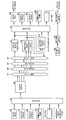
次に、本発明の実施の形態にかかるディジタル・ミキサ1の構成を示すブロック図を図2に示す。
ディジタル・ミキサ1は、ディジタル・ミキサ1の全体の動作を制御すると共に、ミキシング用の操作子やサラウンド操作子の操作に応じて制御信号を生成しているCPU(Central Processing Unit)21と、CPU21が実行するミキシング制御プログラム等の動作ソフトウェアが格納されている書き換え可能な不揮発性のフラッシュメモリ22と、CPU21のワークエリアや各種データ等が記憶されるRAM(Random Access Memory)23を備えている。このように、フラッシュメモリ22に動作ソフトウェアを格納することにより、フラッシュメモリ22内の動作ソフトウェアを書き換えることで、動作ソフトウェアをバージョンアップすることができる。また、信号処理部24は多数のDSPを用いて構成されており、CPU21の制御の元でミキシング処理やサラウンドモニタ処理等を行っている。
【0016】
さらに、アナログオーディオ信号の入出力およびディジタルオーディオ信号の入出力を行う波形データインタフェース(波形I/O)25が設けられている。この波形データインタフェース25に入力されるアナログオーディオ信号は、ステレオのアナログ信号や、オペレータからステージのスタッフへの連絡用の音声信号であるトークバック信号とされ、波形データインタフェース25においてディジタル信号に変換される。また、波形データインタフェース25から外部へ出力されるアナログオーディオ信号は、ステレオモニタ用の出力やサラウンドモニタ用の出力であり、波形データインターフェース25において図示していないキュースイッチを操作したときにそのチャンネルの音が出力されるキュー信号とされる。これらのキュー信号は、波形データインタフェース25においてアナログ信号に変換されて出力されるようになる。
【0017】
さらに、表示器26は、液晶表示器とされており、この表示器26にはミキシングされる各過程におけるディジタル信号のレベルをバーグラフ状に表示することができると共に、サラウンドモニタ設定を行う際にサラウンド設定画面を表示することができる。さらに、電動フェーダ27は後述するミキシングバス(MIXバス)への出力レベルやAUXバスへ送り出される信号のセンドレベルや、バスから出力された信号の出力レベルを調整するフェーダであり、手動および電動により調整することができる。パネル操作子28は、各信号のイコライジング特性やPAN特性等を操作するための多数の操作子であり、サラウンドの設定を行う際に操作子の内のロータリエンコーダやジョイスティックを用いて、2次元定位位置を任意に制御することができるようになされている。
【0018】
その他のインタフェース(その他I/O)29は、DVDドライブ8や外部エフェクタ9との間で信号を授受するためのインタフェースである。さらにまた、信号処理部24は、カードインタフェース(カードI/O)30を介して第1のカード31ないし第6のカード36との間で信号の授受を行うことができるようにされている。第1のカード31ないし第6のカード36は、それぞれカードスロットに装着されており、それぞれのカード31〜36は8チャンネルを有している。そこで、以降の説明では、カード31〜36が有している8チャンネルを「1スロット」という。また、カード31〜36の種類としては、AD変換器を内蔵するアナログイン/ディジタルアウトのカード、ディジタルイン/ディジタルアウトのカード、DA変換器を内蔵するディジタルイン/アナログアウトのカードが用意されている。なお、バス37は各ブロック間でデータをやりとりするための共通路である。ここで、ディジタルイン/ディジタルアウトのカードは、8チャンネル信号のディジタルミキサ1への入力と出力を同時に行うことが可能である。
【0019】
本発明にかかる図2に示す構成のディジタル・ミキサ1におけるミキシング処理およびサラウンド処理が行われる等価的な機能ブロック図を図3に示す。
図3において、24チャンネルを有するアナログ入力ユニット40に入力されたアナログ信号は、内蔵されているAD変換器によりディジタルオーディオ信号に変換されて入力パッチ45に入力されている。また、ステレオ2チャンネルを有するステレオアナログ入力ユニット41に入力されたステレオアナログ入力信号は、内蔵されているAD変換器によりディジタルオーディオ信号に変換されて入力パッチ45に入力されている。さらに、ステレオ3チャンネルを有するステレオディジタル入力ユニット42に入力されたディジタル信号も入力パッチ45に入力されている。以上の入力ユニット40、41、42は、波形I/O25に備えられている。さらに、8チャンネル(1スロット)を備えるカード44から出力されるディジタル信号も入力パッチ45に入力されている。なお、カード44を装着するカードスロットは、前述したように6スロット用意されており最大6枚まで装着することができる。
【0020】
このカード44がアナログイン/ディジタルアウトのカード種類とされて、例えば24トラックレコーダ6において再生された素材用の多チャンネルのサラウンド信号が入力された場合は、内蔵されているAD変換器によりディジタル信号のサラウンド信号に変換されて入力パッチ45に入力される。また、24トラックレコーダ6がディジタルレコーダの場合は、カード44がディジタルイン/ディジタルアウトのカード種類とされる。さらに、カード44から出力されるディジタル信号は出力パッチ54にも入力可能とされている。なお、ディジタル・ミキサ1には8個のエフェクタからなる内蔵エフェクタ43が用意されているが、この内蔵エフェクタ43によりエフェクトの付与された信号も入力パッチ45に入力されている。さらにまた、出力チャンネル部52から出力される8チャンネルのミキシング出力チャンネルおよび12チャンネルのAUX出力チャンネルの信号を、入力パッチ45に入力できるようにされている。
【0021】
入力パッチ45では、入力された複数の信号を、例えば96チャンネルの入力チャンネル部46のそれぞれの入力チャンネルにパッチ(結線)することができる。入力チャンネル部46における各入力チャンネルには、ノイズゲート、コンプレッサ、ディレイ、フェーダ、MIXバス47およびAUXバス50へのセンドレベル調整部が備えられている。これらの入力チャンネルにおいては、周波数特性およびMIXバス47への出力レベルおよびAUXバス50へのセンドレベルが制御されている。入力チャンネル部46から出力される96チャンネルのディジタル信号は、8本のミキシングバス(MIXバス)47の1ないし複数に選択的に出力されると共に、それぞれL,Rのバスからなるステレオバス(Stereo#L/R)48と、それぞれL,Rのバスからなるソロバス(SOLO#L/R)49と、12本のAUXバス50の1ないし複数に選択的に出力される。
【0022】
MIXバス47においては、8本の各バスにおいてミキシングプログラムに応じてそれぞれ選択的に入力された96チャンネルのディジタル信号がミキシングされて、合計8チャンネルのMIX出力が出力チャンネル部(MIX出力ch AUX出力ch)52に出力されている。これにより、最大8通りにミキシングされた8チャンネルのMIX出力を得ることができる。このMIXバス47からの出力が最終的なサラウンド出力となる。また、AUXバス50においては、12本の各バスにおいてミキシングプログラムに応じてそれぞれ選択的に入力された96チャンネルのディジタル信号がミキシングされて、合計12チャンネルのAUX出力が出力チャンネル部52に出力されている。これにより、最大12通りにミキシングされた12チャンネルのAUX出力を得ることができる。このAUXバス50からの出力は中間的なサラウンド出力であり、例えば内蔵エフェクタ43へ送られる。出力チャンネル部52は、イコライザ、コンプレッサ、ディレイ、フェーダ等が備えられている(8+12)チャンネルの出力チャンネルから構成されている。
【0023】
ステレオバス48においては、L,Rのバスにそれぞれ入力された96チャンネルのディジタル信号をプログラムされたとおりにミキシングして、1系統のステレオミキシング出力をステレオ出力チャンネル部51に出力している。ソロバス49においては、L,Rのバスにそれぞれ入力された96チャンネルのディジタル信号の内の1チャンネルがL,Rのバスから出力されて、図示していないがそれぞれの入力チャンネルの出力信号を確認するために出力できるようにされている。
【0024】
ステレオ出力チャンネル部51から出力されるステレオ1チャンネルのステレオミキシング出力と、出力チャンネル部52から出力される(8+12)チャンネルのMIX出力およびAUX出力とは、マトリックス出力チャンネル部(MATRIX 出力 ch)53に選択的に入力されてミキシングされ、4チャンネルのマトリックス出力が生成されている。マトリックス出力チャンネル部53は、イコライザ、コンプレッサ、ディレイ、フェーダ等が備えられている4チャンネルの出力チャンネルから構成されており、その出力チャンネル毎に異なる制御がなされることにより、4系統の異なるマトリックス出力信号を得ることができるようにされている。このマトリックス出力チャンネル部53からの出力はステレオバス48に供給することができ、ステレオバス48においてミキシングされたステレオ信号はステレオ出力チャンネル部51に出力される。
【0025】
上述したステレオ出力チャンネル部51からの1チャンネルのステレオ出力信号と、出力チャンネル部52からの(8+12)チャンネルのMIX出力およびAUX出力と、マトリックス出力チャンネル部53からの4チャンネルのマトリックス出力信号は出力パッチ54に供給される。出力パッチ54では、入力されたディジタル出力信号のそれぞれが、8チャンネルを有するアナログ出力ユニット55、ステレオ1チャンネルを有するステレオアナログ出力ユニット56、ステレオ3チャンネルを有するステレオディジタル出力ユニット57、内蔵エフェクタ(8個)43、および、1カード当たり8チャンネル(1スロット)を有するカード58のいずれかへパッチ(結線)されている。この場合、出力パッチ54に入力される各ディジタル信号は、複数出力先へパッチ(結線)することができる。一方、出力パッチ54における各出力先は、それぞれ1つのディジタル信号しか受けられない。なお、内蔵エフェクタ43では、リバーブ、エコーやコーラスのエフェクトがディジタルオーディオ信号に付加される。この内蔵エフェクタ43は、信号処理部24を構成しているDSPにより実現されている。前述したように、内蔵エフェクタ43の出力は入力パッチ45に入力することができるようにされている。また、カード58からは多チャンネルのサラウンド信号を出力することができ、このサラウンド信号を8トラックマスターレコーダ7に出力して録音することができるようにされている。
【0026】
また、アナログ出力ユニット55へ出力されたディジタル出力信号は、アナログ出力ユニット55に内蔵されているDA変換器によりアナログ出力信号に変換される。この8チャンネルを有するアナログ出力ユニット55には、出力パッチ54において出力チャンネル部52やマトリックス出力チャンネル部53からの多チャンネルのサラウンド信号をパッチすることができる。ここで、図1に示すようにディジタル・ミキサ1から多チャンネルのサラウンドモニタ出力が出力される場合は、アナログ出力ユニット55からサラウンドモニタ出力が出力されるようになる。この多チャンネルのサラウンドモニタ出力は、サラウンドアンプ12で電力増幅されてモニタ用のサラウンドスピーカ13から臨場感あふれた音像で放音される。アナログ出力ユニット55の8チャンネル出力に、8チャンネルのサラウンドアンプ12を接続し、さらに8つのスピーカを接続することにより、最大7.1チャンネルのサラウンドに対応することができる。図1では、例えば、サラウンドアンプ12が8チャンネルを有して5.1チャンネル用アンプに対応しており、モニタ用のサラウンドスピーカ13が5.1チャンネル用に配置(図10(d)参照)されている場合は、アナログ出力ユニット55のチャンネル1が左スピーカチャンネルLに、チャンネル2が右スピーカチャンネルRに、チャンネル3が左後スピーカチャンネルLsに、チャンネル4が後右スピーカチャンネルRsに、チャンネル5がセンタスピーカチャンネルCに、チャンネル6がウーハスピーカチャンネルLFEに割り当てられる。
【0027】
サラウンドモニタ出力について説明すると、ディジタル・ミキサ1におけるパネルには図4に示すモニタ用スイッチが設けられている。このモニタ用スイッチにおけるサラウンドモニタスイッチ71において、スロット選択ボタン71bを操作すると、カード44から出力パッチ54へ入力する複数チャンネル信号が、多チャンネルのモニタ用サラウンド信号として8チャンネルのアナログ出力ユニット55へパッチされるようになる。この場合、例えばアナログ出力ユニット55のチャンネル1ないしチャンネル6に上述した通りの5.1チャンネルにおける各スピーカチャンネルが割り当てられ、カード44からのサラウンド信号がサラウンドモニタ出力としてサラウンドアンプ12で増幅されて、コントロールルームに設置されている5.1チャンネルのモニタ用サラウンドスピーカ13から放音される。これにより、24トラックレコーダ6で再生された多チャンネルのサラウンド信号がカード44に入力されている場合に、このサラウンド信号をそのサラウンド環境においてモニタすることができるようになる。
【0028】
また、サラウンドモニタスイッチ71においてMIXバス選択ボタン71aが操作された場合は、MIXバス47においてミキシングされた多チャンネルのモニタ用サラウンド信号が出力パッチ54でアナログ出力ユニット55へパッチされる。この場合も上記と同様にされて、MIXバス47においてミキシングされた多チャンネルのサラウンド信号がサラウンドモニタ出力としてコントロールルームに設置されている5.1チャンネルのモニタ用サラウンドスピーカから放音される。これにより、MIXバス47においてミキシングされたサラウンド信号を、そのサラウンド環境においてモニタすることができるようになる。
なお、MIXバス47におけるサラウンド・モードがステレオを除く多チャンネルのサラウンド・モードに設定されている場合には、サラウンドモニタスイッチ71におけるMIXバス選択ボタン71aあるいはスロット選択ボタン71bの内の選択操作されているボタンが点灯し、サラウンド・モードがステレオに設定されている場合は、サラウンドモニタスイッチ71におけるいずれのボタンも点灯されない。
【0029】
ところで、上述したように多チャンネルのサラウンド信号をモニタする際には、サラウンドモニタ設定においてモニタされるカード44をスロットの選択を行うことにより選択することができると共に、1スロット8チャンネルを有しているカード44における各チャンネルへのサラウンドチャンネルのパッチ設定(サラウンドモニタパッチ設定)を行うことができるようにされている。この詳細については後述する。
また、出力パッチ54においてステレオアナログ出力ユニット56へパッチされたステレオディジタル出力信号は、ステレオアナログ出力ユニット56に内蔵されているDA変換器によりステレオアナログ出力信号に変換されて出力される。このステレオアナログ出力信号は、8トラックマスターレコーダ7等に録音することができる。さらに、出力パッチ54においてステレオディジタル出力ユニット57へパッチされたステレオディジタル出力信号は、DAT等に供給されてディジタル録音することができるようにされている。なお、以上に説明した出力ユニット55、56、57は、波形I/O25に備えられている。
【0030】
さらに、1スロット8チャンネルを備えるカード58は、ディジタルイン/ディジタルアウトあるいはディジタルイン/アナログアウトのカードとされ、出力パッチ54において出力チャンネル部52やマトリックス出力チャンネル部53からの多チャンネルのサラウンド信号をパッチすることができるようにされている。出力パッチ54においてカード58へパッチされた多チャンネルのサラウンド信号出力は、ディジタルイン/アナログアウトのカード種類とされている場合は、カード58に内蔵されているDA変換器によりアナログのサラウンド信号に変換されて出力される。このサラウンド信号は、8トラックマスターレコーダ7等に録音することができるようにされている。また、ディジタルイン/ディジタルアウトのカード種類とされている場合は、出力されるディジタルのサラウンド信号をディジタルレコーダ等に録音することができるようにされている。
ここで、カード58にAUXバス50でミキシングされたAUX出力がパッチされた場合、このAUX出力を外部エフェクタ9に供給することができるようにされている。内蔵エフェクタ43や外部エフェクタ9においては、複数チャンネルにエフェクトを付与することができるようにされている。付与できるエフェクトは、例えば、1入力6出力のリバーブ、2入力2出力の3バンド・バンド別リミッタ、コンプレッサ、エキスパンダ、4入力4出力のリバーブやコンプレッサとされている。内蔵エフェクタ43によりエフェクトの付与された信号は、入力パッチ45に入力される。
【0031】
ところで、ディジタル・ミキサ1においては、ステレオバス48に入力されるステレオ信号やミキシングされて出力されるステレオ信号、ステレオ出力チャンネル部51からのステレオ信号を、選択的にあるいは加算してモニタすることができるようにされている。いずれのステレオ出力信号をモニタするかのモニタ信号の選択は、図4に示すステレオモニタスイッチ70であるモニタ用セレクタ59により行われる。この場合、ステレオ出力チャンネル51、ステレオアナログ出力ユニット56、ステレオディジタル出力ユニット57、その他アサインされた出力チャンネル52から、2以上のステレオ信号を選択することができ、選択されたモニタ用ステレオ信号はモニタ用ミキサ60においてミキシングされ、ステレオアンプ10で電力増幅されてモニタ用のステレオスピーカ11あるいはモニタ用のヘッドフォンから放音される。
【0032】
次に、本発明にかかるディジタル・ミキサ1におけるサラウンドモニタ設定の説明を行う。
図5は、用意された6スロットのカード44が装着されるスロットの内の、モニタするスロットの設定を行うサラウンドモニタ設定1の表示画面であり、MIXバス47における各バス対応の出力チャンネルのミュート設定も行うことができる。この画面は表示器26に表示される画面であり、表示領域80にはMIXバス47に設定されているサラウンド・モードが5.1チャンネルとされている場合が示されている。このサラウンド・モードの表示は、5.1チャンネルのサラウンドスピーカの配置を示すスピーカアイコン82,83・・・で示されており、各スピーカアイコン82,83・・・の近傍に、そのスピーカチャンネルへ出力するMIXバス47におけるバスBUS1〜BUS6が表示されている。また、左スピーカLと右スピーカRのアイコン83だけがオンされてミュートされていないことが示されて(表示が白抜きとなる)いる。他のスピーカLs、Rs、C、LFEは、そのスピーカアイコン82,・・・がオフされてミュートされていることが示されている。各スピーカのアイコンの近傍にはレベル表示部84,85・・・が表示されており、ミュートされていないスピーカに供給されるサラウンド信号のレベルが図示するようにメータ表示されている。ここで、ソロボタン81を操作するとミュートは一旦解除され、最後に選択した出力のみが出力されるようになる。
【0033】
また、表示画面における領域90ではスロットボタン91とスロット番号92が表示されて、モニタするスロットを選択して設定するようにしている。図示する例では、スロット1とスロット3が選択されてモニタされるように設定されている。このようにスロット1とスロット3が選択されている場合は、スロット1およびスロット3の多チャンネルのサラウンド信号がチャンネル毎に加算されて、サラウンドモニタ出力とされる。ここでのスロットを選択するサラウンドモニタの設定は、図4に示すスロット選択ボタン71bが操作された時や表示されているスロットボタン91を操作した時に有効となって、スロット1,3に対応するカード44に入力される多チャンネルのサラウンド信号が加算されて、サラウンドモニタ出力とされる。このサラウンドモニタ出力は、アナログ出力ユニット55に出力され上述したようにモニタされるようになる。この際のモニタ用サラウンド信号のレベルは、図4に示すボリューム72により調整することができるようにされている。
さらに、表示画面における領域95にはサラウンドに関するステータスが表示されている。すなわち、表示欄96にMIXバス47におけるサラウンド・モードが5.1チャンネルとされていること、および、表示欄97にボリューム72を調整した結果のサラウンドモニタ出力のモニタレベルが0dBとされていることが示されている。
【0034】
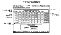
次に、カード44における各チャンネルからサラウンドチャンネル(アナログ出力ユニット55の各チャンネルに対応)へのパッチ設定を行うサラウンドモニタ設定2の表示画面を図6に示す。
図6に示すように表示領域101は、サラウンドモニタパッチを設定する領域とされており上部にスロット1ないしスロット6がそれぞれ有しているチャンネル1(CH1)〜チャンネル8(CH8)のチャンネル番号102が表示され、左側には上からスロット1(SLOT1),スロット2(SLOT2),・・・・・スロット6(SLOT6)のスロット番号103が表示されている。さらに、チャンネル番号102とスロット番号103からなるマトリクスに、パッチされたそれぞれのサラウンドチャンネル104が表示されている。ここで、各サラウンドチャンネル104は、現在選択されているサラウンドモード(この場合は、5.1チャンネルサラウンド)に対応したサラウンドチャンネルの何れかである。この多チャンネルからなるサラウンドチャンネル104を、各スロット1〜6におけるチャンネルCH1〜CH8の各チャンネルにパッチするのが、サラウンドモニタ設定2とされている。
【0035】
サラウンドチャンネル104は、サラウンド・モードにおいて配置されるスピーカに対応している。例えば、スロット1(SLOT1)から6チャンネルの信号(チャンネル順に、L,R,Ls,Rs,C,LFE)を入力しており、図6のように5.1チャンネルにおける6チャンネルからなるサラウンドチャンネルがパッチされている。すなわち、CH1に左スピーカ用のサラウンドチャンネルLが、CH2に右スピーカ用のサラウンドチャンネルRが、CH3に左後スピーカ用のサラウンドチャンネルLsが、CH4に右後スピーカ用のサラウンドチャンネルLsが、CH5にセンタスピーカ用のサラウンドチャンネルCが、CH6にウーハ用のサラウンドチャンネルLが、それぞれパッチされ、CH7,CH8にはサラウンドチャンネルはパッチされていない。以上のパッチ設定により、スロット1のサラウンドモニタがオンされたときには、出力パッチ54にて次のように結線される。スロット1に挿入されたカード44のチャンネル1は、通常、MIXバス1(5.1チャンネルモードにおけるサラウンドチャンネルL)の出力チャンネルがパッチされているサラウンドモニタ出力(例えばアナログ出力ユニットのチャンネル1)に、該出力チャンネルの代りにアナログ出力ユニットのチャンネル1にパッチ(結線)される。スロット1に挿入されたカード44のチャンネル2は、MIXバス2(5.1チャンネルモードにおけるサラウンドチャンネルR)の出力チャンネルの代りにアナログ出力ユニットのチャンネル2にパッチされる。また、スロット1に挿入されたカード44のチャンネル3は、MIXバス3(5.1チャンネルモードにおけるサラウンドチャンネルLs)の出力チャンネルの代りにアナログ出力ユニットのチャンネル3にパッチされる。以下、スロット1に挿入されたカード44のチャンネル4〜6も同様にパッチされる。また、スロット2(SLOT2)には、図示するように5.1チャンネルにおけるサラウンドチャンネルが異なる態様でパッチされ、スロット3(SLOT3)には、5.1チャンネルにおけるサラウンドチャンネルがスロット1と同様にパッチされている。さらにまた、スロット4(SLOT4)ないしスロット(SLOT6)におけるチャンネルCH1〜CH8にはサラウンドチャンネルはパッチされていない。なお、各スロットにパッチされたサラウンドチャンネル104をクリアするためのクリアボタン105が、表示領域101の右側に各スロット1〜6毎に表示されている。
【0036】
ところで、カード44からの多チャンネルのサラウンド信号をサラウンドモニタ出力する場合に、カード44からの多チャンネルのサラウンド信号のサラウンド・モードが5.1チャンネル以外のモードとされている場合がある。この場合には、図6に示すサラウンドモニタ設定2においてチャンネルCH1〜CH8へのサラウンドチャンネル104のパッチを変更するようにする。例えば、カード44のスロット4に装着されたディジタルイン/ディジタルアウトのカード44から(2+2)チャンネル構成の信号(チャンネル順に、L,R,Ls,Rs)を入力する場合は、CH1に左スピーカ用のサラウンドチャンネルLを、CH2に右スピーカ用のサラウンドチャンネルRを、CH3に左後スピーカ用のサラウンドチャンネルLsを、CH4に右後スピーカ用のサラウンドチャンネルRsをパッチし、チャンネルCH5〜CH8にはサラウンドチャンネルをパッチしないようにする。これにより、5.1チャンネル用に配置されているサラウンドスピーカにおいて、(2+2)チャンネルのサラウンド・モードのサラウンドモニタ出力をモニタすることができるようになる。また、サラウンド・モードによってはこのようにパッチを変更しても対応できない場合があるが、この場合はサラウンドモニタ出力の経路上にサラウンド・モード変換器を設けて、このサラウンド・モード変換器によりサラウンド・モードを変更すればよい。サラウンド・モード変換器は信号処理部24におけるDSPにより実現させればよい。
【0037】
なお、サラウンドモニタ出力としては、MIXバス選択ボタン71aを操作した場合に前述したようにMIXバス47からの多チャンネルのサラウンド信号が出力される。この場合においてサラウンドモニタパッチの設定を行わないのは次の理由による。MIXバス47は8本用意されているが、これらのMIXバス47におけるサラウンドチャンネルへの割当は図9に示すように固定されている。すなわち、サラウンド・モードが5.1チャンネルに設定された場合は、MIXバス47におけるバス1(BUS1)に左スピーカ用のサラウンドチャンネルLが割り当てられ、バス2(BUS2)に右スピーカ用のサラウンドチャンネルRが割り当てられ、バス3(BUS3)に左後スピーカ用のサラウンドチャンネルLsが割り当てられ、バス4(BUS4)に右後スピーカ用のサラウンドチャンネルRsが割り当てられ、バス5(BUS5)にセンタースピーカ用のサラウンドチャンネルCが割り当てられ、バス6(BUS6)にウーハ用スピーカのサラウンドチャンネルLFEが固定的に割り当てられる。この割当は、前述した8チャンネルを有するアナログ出力ユニット55における各チャンネルへの5.1チャンネルの各スピーカチャンネルの割当に相当している。このため、サラウンドモニタ出力として、MIXバス47からの多チャンネルサラウンド信号が出力される場合は、出力パッチ54においてMIXバス47のバス1〜バス6をアナログ出力ユニットのチャンネル1〜チャンネル6にパッチすればよいからである。なお、他のサラウンド・モードに設定された場合には、そのサラウンド・モードにおけるMIXバス47のサラウンドチャンネル構成に合わせるように、ユーザは、アナログ出力ユニット55に接続されるサラウンドスピーカを変更する。
【0038】
次に、上述したサラウンドモニタ設定1において、モニタするスロットを設定する際のSLOTnオン処理のフローチャートを図7(a)に示す。
図5に示すサラウンドモニタ設定1の画面において領域90に表示されたスロット番号92のSLOTnがオンされるとSLOTnオン処理が開始され、ステップS10にて図6に示すサラウンドモニタ設定2において設定されたスロットnのサラウンドモニタパッチ設定に従って、オンされたスロットnとアナログ出力ユニット55間のサラウンドモニタ結線が出力パッチ54にて設定される。
次に、上述したサラウンドモニタ設定1において、モニタするスロットを設定する際のSLOTnオフ処理のフローチャートを図7(b)に示す。
図5に示すサラウンドモニタ設定1の画面において領域90に表示されたスロット番号92のSLOTnがオフされると、SLOTnオフ処理が開始され、ステップS20にてオフされたスロットnとアナログ出力ユニット55間のサラウンドモニタ結線が解除される。
【0039】
次に、サラウンドモニタスイッチ71におけるスロット選択ボタン71bをオン/オフした際に実行されるSLOTスイッチオン処理のフローチャートを図8に示す。
サラウンドモニタスイッチ71におけるスロット選択ボタン71bが操作されるとSLOTスイッチオン/オフ処理が開始され、ステップS31にてフラグSMON(サラウンドモニタ)が「1」か否かが判断される。この場合、スロット選択ボタン71bがオン状態の場合にSMONは「1」となり、スロット選択ボタン71bがオフ状態の場合にSMONは「0」となる。ところで、MIXバスボタン71aがオフ状態、かつ、スロット選択ボタン71bがオフ状態の場合は、MIXバスボタン71aを操作すると、MIXバスボタン71aがオン状態になり、スロット選択ボタン71bを操作すると、スロット選択ボタン71bがオン状態になる。また、MIXバスボタン71aがオン状態、かつ、スロット選択ボタン71bがオフ状態の場合は、MIXバスボタン71aを操作すると、MIXバスボタン71aがオフ状態になり、スロット選択ボタン71bを操作すると、MIXバスボタン71aがオフ状態になると共に、スロット選択ボタン71bがオン状態になる。さらに、MIXバスボタン71aがオフ状態、かつ、スロット選択ボタン71bがオン状態の場合は、MIXバスボタン71aを操作すると、スロット選択ボタン71bがオフ状態になると共に、MIXバスボタン71aがオン状態になり、スロット選択ボタン71bを操作すると、スロット選択ボタン71bがオフ状態になる。そこで、スロット選択ボタン71bがオン状態とされてフラグSMONが「1」となっている場合は、ステップS32に進んでサラウンドモニタ出力として設定されているスロットの出力がオンされる。これにより、外部から入力された素材用の多チャンネルのサラウンド信号がモニタされるようになる。また、ステップS31にてフラグSMONが「1」とされていないと判断された場合は、ステップS33に進んでサラウンドモニタ出力として設定されているスロットがオフされる。ここで、MIXバスボタン71aがオン状態とされている場合は、MIXバス47においてミキシングされた多チャンネルのサラウンド信号がサラウンドモニタ出力とされるようになる。これにより、MIXバス47においてミキシングされた多チャンネルのサラウンド信号がモニタされるようになる。
【0040】
なお、以上説明した本発明の実施の形態のディジタル・ミキサでは、スロットからのサラウンドモニタを選択するスロット選択ボタン71bが1つだけであったが、スロット選択ボタン71bを複数設けるようにしてもよい。その場合、複数のスロット選択ボタン71bに対応させて、図5に示すサラウンドモニタ設定1の画面における表示領域90に複数のスロットボタン91と複数のスロット番号92を表示し、そこで各ボタンでモニタするスロットのオン/オフを設定するようにしてもよい。この場合、複数のスロット選択ボタン71bは同時に複数オン可能とし、オンされた複数のスロット選択ボタンの何れかでオンされているスロットが複数同時にモニタできるようにするとよい。また、図6に示すサラウンドモニタ設定2の画面では、カード44の各チャンネルをサラウンドチャンネルにパッチするようになっているが、その代りに、カード44の各チャンネルをアナログ出力ユニット55の各チャンネルに直接にパッチするようにしてもよい。
【0041】
さらに、本発明の実施の形態のディジタル・ミキサにおいては、スロット毎にサラウンドモニタパッチを設定するようになっていたが、必ずしもスロット毎に設定しなくてもよい。入力パッチに入力する複数入力を任意の方法で複数のグループに分け、その各グループ毎にサラウンドモニタパッチを設定できるようになっていればよい。さらにまた、図1に示す構成では、ステレオモニタ用スピーカ11とサラウンドモニタ用スピーカ13を別個に設けていたが、サラウンドモニタ用スピーカ13の前左スピーカLと前右スピーカRを、ステレオモニタ用スピーカとして共用するようにしてもよい。
【0042】
【発明の効果】
本発明は以上説明したように、多チャンネルのサラウンド信号をサラウンドモニタ出力として出力する経路を設けるようにしたので、外部から入力された素材用の多チャンネルのサラウンド信号やミキシングバスから出力される録音用の多チャンネルのサラウンド信号をモニタすることができるようになる。
この場合、特定のサラウンド・モードに対応したスピーカに送られる多チャンネルのサラウンド信号のサラウンド・モードと、特定のサラウンド・モードとが一致しない場合は、サラウンドモニタ出力が特定のサラウンド・モードになるように変換することができるようにされている。
【図面の簡単な説明】
【図1】 本本発明の実施の形態のディジタル・ミキサと、ディジタル・ミキサに接続される周辺機器との構成を示すブロック図である。
【図2】 本発明の実施の形態にかかるディジタル・ミキサの構成を示すブロック図である。
【図3】 本発明にかかる図2に示す構成のディジタル・ミキサにおけるミキシング処理が行われる等価的な機能ブロック図である。
【図4】 本発明の実施の形態にかかるディジタル・ミキサのパネルに備えられているモニタ用スイッチの構成を示す図である。
【図5】 本発明の実施の形態にかかるディジタル・ミキサにおけるサラウンドモニタ設定1の画面を示す図である。
【図6】 本発明の実施の形態にかかるディジタル・ミキサにおけるサラウンドモニタ設定2の画面を示す図である。
【図7】 本発明の実施の形態にかかるディジタル・ミキサにおけるスロットnオン処理、スロットnオフ処理のフローチャートである。
【図8】 本発明の実施の形態にかかるディジタル・ミキサにおけるスロットスイッチオン/オフ処理のフローチャートである。
【図9】 本発明の実施の形態にかかるディジタル・ミキサにおけるMIXバスのサラウンドチャンネルへの割当を示す図表である。
【図10】 サラウンド・モードとそのスピーカ配置を示す図である。
【図11】 他のサラウンド・モードとそのスピーカ配置を示す図である。
【符号の説明】
1 ディジタル・ミキサ、2,3 マイク、4,5 楽器、6 24トラックレコーダ、7 8トラックマスターレコーダ、8 DVDドライブ、9 外部エフェクタ、10 ステレオアンプ、11 ステレオスピーカ、12 サラウンドアンプ、13 サラウンドスピーカ、21 CPU、22 フラッシュメモリ、23 RAM、24 信号処理部、25 波形データインタフェース、26 表示器、27 電動フェーダ、28 パネル操作子、29 その他I/O、30 カードI/O、31〜36 カード、37 バス、40 アナログ入力ユニット、41 ステレオアナログ入力ユニット、42 ステレオディジタル入力ユニット、43 内蔵エフェクタ、44 カード、45 入力パッチ、46 入力チャンネル部、47 MIXバス、48 ステレオバス、49 ソロバス、50 AUXバス、51 ステレオ出力チャンネル部、52 出力チャンネル部、53 マトリックス出力チャンネル部、54 出力パッチ、55 アナログ出力ユニット、56 ステレオアナログ出力ユニット、57 ステレオディジタル出力ユニット、58 カード、59 モニタ用セレクタ、60 モニタ用ミキサ、61 モニタ用アナログ出力、70 ステレオモニタスイッチ、71 サラウンドモニタスイッチ、71a MIXバス選択ボタン、71b スロット選択ボタン、72ボリューム、80 表示領域、81 ソロボタン、82,83 スピーカアイコン、84,85 レベル表示部、90 領域、91 スロットボタン、92 スロット番号、95 領域、96 表示欄、97 表示欄、101 表示領域、102 チャンネル番号、103 スロット番号、104 サラウンドチャンネル、105 クリアボタン[0001]
[Technical field to which the invention belongs]
The present invention relates to a digital mixer capable of monitoring a multi-channel surround signal.
[0002]
[Prior art]
Conventionally, mixing consoles that adjust the level and frequency characteristics of audio signals output from a large number of microphones or electric / electronic musical instruments, mix them, and send them to a power amplifier in several mixing groups are known. . The operator who operates the mixing console seems to represent the performance most appropriately by operating the various panel controls provided on the mixing console for the volume and tone of each audio signal of instrument sounds and singing. It is adjusted to the state that can be. The mixing console includes a plurality of microphone / line input channels as input signal sequences, and the input signal sequences are programmed and mixed, and output to a plurality of output channels that are output signal sequences. The signal of each input channel in the input signal series is generally amplified by a head amplifier and output to a mixing processing unit. Then, frequency characteristics and levels are adjusted in the mixing processing unit, and mixing is performed in the programmed combination. Next, the output fader is set to an arbitrary output level and output to one of the output channels.
[0003]
[Problems to be solved by the invention]
Such mixing consoles are used in theaters and concert halls, and in recording studios for creating music sources for recording on compact discs (CDs) and the like. For example, in a mixing console in a recording studio, performance sounds and singing sounds for materials are input. The mixing console adjusts the levels and frequency characteristics of a large number of input signals, mixes them in a desired combination, and adjusts and outputs the level of the mixing output. In such a mixing console, a digital mixer is known in which mixing processing is performed by digital processing using a DSP or the like.
[0004]
By the way, in a theater or the like, a plurality of speakers are arranged in front and rear so as to make the audience feel more realistic, so that a sound field with high presence is created. Such a system that generates a highly realistic sound field is referred to as a surround system, and is capable of outputting a mixing signal capable of exhibiting a surround effect in a digital mixer as a music source for recording. Various surround modes have been proposed for surround. Some outlines are shown in FIGS.
The surround mode shown in FIG. 10A is stereo, and the left speaker L and the right speaker R are arranged in front so as to obtain a sense of reality. The surround mode shown in FIG. 10B is a (2 + 2) channel mode, in which the left speaker L and the right speaker R are arranged in the front, and the left rear speaker Ls and the right rear speaker Rs are arranged in the rear. To get a sense of realism. Further, the surround mode shown in FIG. 10 (c) is the (3 + 1) channel mode, in which the left speaker L and the right speaker R are arranged in the front, and the center speaker C is arranged in the center thereof, and the rear speaker S is arranged in the rear center. To get a sense of realism.
[0005]
Furthermore, the surround mode shown in FIG. 10 (d) is a 5.1 channel mode, in which a left speaker L and a right speaker R are disposed in front, and a center speaker C is disposed in the center thereof, and a left rear speaker is disposed in the rear. Ls and the right rear speaker Rs are arranged, and the woofer speaker LFE is arranged in an appropriate position so as to obtain a sense of reality. Furthermore, the surround mode shown in FIG. 11A is a 6.1 channel mode, in which a left speaker L and a right speaker R are arranged in the front, and a center speaker C is arranged in the center thereof, and a left rear speaker in the rear. Ls, the right rear speaker Rs, and the rear center speaker Cs are arranged at the center thereof, and the woofer speaker LFE is arranged at an appropriate position so as to obtain a sense of reality. Furthermore, the surround mode shown in FIG. 11 (b) is a 7.1 channel mode, in which the left speaker L and the right speaker R are in front, the center speaker C in the center, and between the left speaker L and the center speaker C. The speaker Lc is disposed between the right speaker R and the center speaker C, the left rear speaker Ls and the right rear speaker Rs are disposed at the rear, and the woofer speaker LFE is disposed at an appropriate place. I try to get a feeling. In the following description, the surround modes shown in FIGS. 10B to 11B other than the surround mode shown in FIG. 10A are referred to as multi-channel surround modes.
[0006]
As described above, there are various modes for the surround mode, and in order to localize the sound to a predetermined position in the selected surround mode, a level corresponding to the surround mode and the localization position is set for the arranged speaker. An adjusted surround signal is supplied. However, even though the digital mixer has such a surround mode, the monitor output of the surround signal in the multi-channel surround mode exceeding stereo cannot be output. There is a problem that the surround signal cannot be monitored.
[0007]
SUMMARY OF THE INVENTION An object of the present invention is to provide a digital mixer that can monitor a multi-channel surround signal.
[0008]
[Means for Solving the Problems]
In order to achieve the above object, the digital mixer of the present invention has a plurality of input signals inputted from the outside. Via multiple input channels The signal is selectively sent to a mixing bus section composed of a plurality of buses, and the transmitted signal is mixed in each bus of the mixing bus section. Output channel of speaker position corresponding to each bus A digital mixer in which a plurality of input signals input from the outside are converted into a multi-channel surround signal, and a multi-channel surround signal is mixed and output in the mixing bus section, wherein the mixing section And an output section having a plurality of monitor output channels corresponding to the channel configuration of the multi-channel surround signal, and the channel configuration of the multi-channel surround signal input from the outside as the monitor output , The signal of each input channel corresponds to the speaker position of the input channel The multi-channel surround signal in the output section. Monitor output For channel configuration As introduced By converting and supplying the converted multi-channel surround signal to the output section. Depending on the corresponding monitor output channel A path for direct monitor output and a path for supplying a monitor output by supplying a multi-channel surround signal output from the mixing bus section to the output section are selectable.
[0009]
In the digital mixer of the present invention, as a plurality of input signals input from the outside, input Channel Between speaker and speaker position A plurality of sets of multi-channel surround signals can be input from the outside, and one of the plurality of sets of channel configurations is selected and the channel configuration of the multi-channel surround signals input from the outside is converted. The route for monitor output is Set Channel configuration Each input channel of the set corresponds to the speaker position of the input channel The multi-channel surround signal in the output section. Monitor output Channel As introduced in You may make it convert.
[0010]
Next, according to another digital mixer of the present invention capable of achieving the above object, input signals from a plurality of inputs grouped into a plurality of groups inputted from the outside are received. Via multiple input channels The signal is selectively sent to a mixing bus section composed of a plurality of buses, and the transmitted signal is mixed in each bus of the mixing bus section. Output channel of speaker position corresponding to each bus A surround mode designating unit for designating a surround mode in the mixing bus section, and an input signal from the plurality of inputs designated by the surround mode designating unit. An input channel means for performing surround volume control according to the surround mode and selectively outputting to the mixing bus section, and a monitor sound system prepared corresponding to the channel configuration of the surround mode, In response to a predetermined first monitor operation, First monitor control means for controlling to supply a multi-channel mixing signal having a channel configuration corresponding to the surround mode mixed in the mixing bus section to the monitoring sound system; Depending on the predetermined setting operation, A plurality of inputs included in the grouped group Correspondence between channel and speaker position corresponding to the channel For each group Setting Channel configuration Setting Means, In response to a predetermined second monitor operation, Selecting at least one of the grouped groups, and input signals from a plurality of inputs in the selected group, Setting By means Setting Channel of the group concerned And each channel based on the correspondence between the corresponding speaker position , A channel corresponding to the surround mode specified by the surround mode specifying means As introduced in And second monitor control means for controlling the input signal of the converted channel configuration to be supplied to the monitor sound system.
The digital mixer according to the present invention further includes a plurality of slots to which input means for inputting the external multi-channel surround signal is connected, and the input signals are grouped for each slot. It may be a thing.
[0011]
According to the present invention, since a path for outputting a multi-channel surround signal as a surround monitor output is provided, a multi-channel surround signal for material input from the outside or a recording bus output from a mixing bus is provided. Multi-channel surround signals can be monitored.
In this case, if the surround mode of the multi-channel surround signal sent to the speaker corresponding to the specific surround mode does not match the specific surround mode, the surround monitor output is set to the specific surround mode. Has been able to be converted to.
[0012]
DETAILED DESCRIPTION OF THE INVENTION
FIG. 1 shows a configuration of a digital mixer according to an embodiment of the present invention and peripheral devices connected to the digital mixer.
The
[0013]
In the
[0014]
When the
[0015]
Next, a block diagram showing the configuration of the
The
[0016]
Further, a waveform data interface (waveform I / O) 25 for inputting / outputting analog audio signals and digital audio signals is provided. The analog audio signal input to the
[0017]
Further, the
[0018]
The other interface (other I / O) 29 is an interface for exchanging signals with the
[0019]
FIG. 3 shows an equivalent functional block diagram in which mixing processing and surround processing are performed in the
In FIG. 3, the analog signal input to the
[0020]
When this card 44 is of an analog in / digital out card type and, for example, a multi-channel surround signal for material reproduced by the 24-
[0021]
In the
[0022]
In the
[0023]
In the
[0024]
The
[0025]
The 1-channel stereo output signal from the stereo
[0026]
The digital output signal output to the
[0027]
The surround monitor output will be described. The monitor switch shown in FIG. 4 is provided on the panel of the
[0028]
When the MIX
Note that when the surround mode in the
[0029]
By the way, when monitoring a multi-channel surround signal as described above, the card 44 to be monitored in the surround monitor setting can be selected by selecting a slot, and one slot has 8 channels. The surround channel patch setting (surround monitor patch setting) for each channel in the card 44 can be performed. Details of this will be described later.
The stereo digital output signal patched to the stereo
[0030]
Further, the card 58 having one slot and eight channels is a digital in / digital out or digital in / analog out card, and multi-channel surround signals from the
Here, when the AUX output mixed by the
[0031]
By the way, in the
[0032]
Next, surround monitor setting in the
FIG. 5 is a display screen of surround monitor setting 1 for setting a slot to be monitored among the slots in which the prepared six-slot cards 44 are installed. Settings can also be made. This screen is a screen displayed on the
[0033]
Further, a
Furthermore, a status relating to surround is displayed in an
[0034]
Next, FIG. 6 shows a display screen of surround monitor setting 2 for performing patch setting from each channel in the card 44 to the surround channel (corresponding to each channel of the analog output unit 55).
As shown in FIG. 6, the
[0035]
The
[0036]
By the way, when the multi-channel surround signal from the card 44 is output to the surround monitor, the surround mode of the multi-channel surround signal from the card 44 may be a mode other than 5.1 channel. In this case, the
[0037]
As the surround monitor output, a multi-channel surround signal is output from the
[0038]
Next, FIG. 7A shows a flowchart of SLOTn ON processing when setting a slot to be monitored in the surround monitor setting 1 described above.
When the SLOTn of the
Next, FIG. 7B shows a flowchart of the SLOTn off process when setting the slot to be monitored in the surround monitor setting 1 described above.
When SLOTn of
[0039]
Next, FIG. 8 shows a flowchart of the SLOT switch on process executed when the slot selection button 71b in the surround monitor switch 71 is turned on / off.
When the slot selection button 71b in the surround monitor switch 71 is operated, the SLOT switch on / off process is started, and it is determined in step S31 whether or not the flag SMON (surround monitor) is “1”. In this case, SMON is “1” when the slot selection button 71b is in the on state, and SMON is “0” when the slot selection button 71b is in the off state. By the way, when the
[0040]
In the digital mixer according to the embodiment of the present invention described above, there is only one slot selection button 71b for selecting the surround monitor from the slot. However, a plurality of slot selection buttons 71b may be provided. . In that case, a plurality of
[0041]
Furthermore, in the digital mixer according to the embodiment of the present invention, the surround monitor patch is set for each slot, but it is not always necessary to set it for each slot. It suffices that a plurality of inputs to be input to the input patch are divided into a plurality of groups by an arbitrary method, and a surround monitor patch can be set for each group. Furthermore, in the configuration shown in FIG. 1, the
[0042]
【The invention's effect】
As described above, since the present invention provides a path for outputting a multi-channel surround signal as a surround monitor output, a multi-channel surround signal for externally input material or a recording bus output from a mixing bus is provided. Multi-channel surround signals can be monitored.
In this case, if the surround mode of the multi-channel surround signal sent to the speaker corresponding to the specific surround mode does not match the specific surround mode, the surround monitor output is set to the specific surround mode. Has been able to be converted to.
[Brief description of the drawings]
FIG. 1 is a block diagram showing a configuration of a digital mixer according to an embodiment of the present invention and peripheral devices connected to the digital mixer.
FIG. 2 is a block diagram showing a configuration of a digital mixer according to an embodiment of the present invention.
FIG. 3 is an equivalent functional block diagram in which mixing processing is performed in the digital mixer having the configuration shown in FIG. 2 according to the present invention.
FIG. 4 is a diagram showing a configuration of a monitor switch provided in the panel of the digital mixer according to the embodiment of the present invention.
FIG. 5 is a diagram showing a screen of surround monitor setting 1 in the digital mixer according to the embodiment of the present invention.
FIG. 6 is a diagram showing a screen of surround monitor setting 2 in the digital mixer according to the embodiment of the present invention.
FIG. 7 is a flowchart of slot n-on processing and slot n-off processing in the digital mixer according to the embodiment of the present invention.
FIG. 8 is a flowchart of slot switch on / off processing in the digital mixer according to the embodiment of the present invention;
FIG. 9 is a chart showing assignment of MIX buses to surround channels in the digital mixer according to the embodiment of the present invention;
FIG. 10 is a diagram showing a surround mode and its speaker arrangement.
FIG. 11 is a diagram showing another surround mode and its speaker arrangement.
[Explanation of symbols]
1 Digital mixer, 2, 3 microphones, 4, 5 musical instruments, 6 24-track recorder, 7 8-track master recorder, 8 DVD drive, 9 external effector, 10 stereo amplifier, 11 stereo speaker, 12 surround amplifier, 13 surround speaker, 21 CPU, 22 Flash memory, 23 RAM, 24 Signal processor, 25 Waveform data interface, 26 Display, 27 Electric fader, 28 Panel operator, 29 Other I / O, 30 Card I / O, 31-36 Card, 37 buses, 40 analog input units, 41 stereo analog input units, 42 stereo digital input units, 43 built-in effectors, 44 cards, 45 input patches, 46 input channel sections, 47 MIX buses, 48 stereo buses, 49 solo buses, 0 AUX bus, 51 stereo output channel section, 52 output channel section, 53 matrix output channel section, 54 output patch, 55 analog output unit, 56 stereo analog output unit, 57 stereo digital output unit, 58 card, 59 selector for monitor, 60 monitor mixer, 61 monitor analog output, 70 stereo monitor switch, 71 surround monitor switch, 71a MIX bus selection button, 71b slot selection button, 72 volume, 80 display area, 81 solo button, 82, 83 speaker icon, 84 , 85 level display section, 90 area, 91 slot button, 92 slot number, 95 area, 96 display field, 97 display field, 101 display area, 102 channel number, 103 slot number, 10 4 surround channels, 105 clear button
Claims (4)
前記ミキシングセクションにおける多チャンネルのサラウンド信号のチャンネル構成に対応する複数のモニタ出力チャンネルを有する出力セクションを備え、
モニタ出力として、前記外部から入力された多チャンネルのサラウンド信号のチャンネル構成を、各入力チャンネルの信号が該入力チャンネルのスピーカ位置に対応する前記出力セクションにおける多チャンネルサラウンド信号のモニタ出力チャンネル構成に導入されるよう変換し、前記出力セクションに該変換された多チャンネルサラウンド信号を供給することにより、外部から入力する多チャンネルサラウンド信号をそれぞれ対応するモニタ出力チャンネルにより直接的にモニタ出力する経路と、前記ミキシングバスセクションから出力される多チャンネルのサラウンド信号を前記出力セクションに供給してモニタ出力する経路とが選択可能に設けられていることを特徴とするディジタル・ミキサ。A plurality of input signals input from the outside are selectively sent to a mixing bus section consisting of a plurality of buses via a plurality of input channels, and the transmitted signals are mixed in each bus of the mixing bus section to be transmitted to each bus. Is output to the output channel at the speaker position corresponding to the multi-channel surround signal from a plurality of externally input signals, and the multi-channel surround signal is mixed and output in the mixing bus section. A mixer,
An output section having a plurality of monitor output channels corresponding to a channel configuration of a multi-channel surround signal in the mixing section;
As the monitor output, the channel configuration of the multi-channel surround signal input from the outside is introduced into the monitor output channel configuration of the multi-channel surround signal in the output section where the signal of each input channel corresponds to the speaker position of the input channel. converts to be, by supplying multi-channel surround signal said converted into the output section, the path that directly monitor output by the monitor output channel corresponding multi-channel surround signal input from the outside, respectively, the A digital mixer characterized in that a multi-channel surround signal output from a mixing bus section is supplied to the output section and monitored.
前記外部から入力された多チャンネルサラウンド信号のチャンネル構成を変換してモニタ出力する経路は、前記選択されたセットのチャンネル構成を該セットの各入力チャンネルが該入力チャンネルのスピーカ位置に対応する前記出力セクションにおける多チャンネルサラウンド信号のモニタ出力チャンネルに導入されるよう変換することを特徴とする請求項1記載のディジタル・ミキサ。As a plurality of input signals input from the outside, a plurality of sets of multi-channel surround signals having different correspondences between input channels and speaker positions can be input from the outside, and any one of the plurality of sets of channel configurations Select
The path for converting and monitoring the channel configuration of the multi-channel surround signal input from the outside is the output of the selected set channel configuration in which each input channel of the set corresponds to the speaker position of the input channel. 2. The digital mixer according to claim 1, wherein the digital mixer is converted to be introduced into a monitor output channel of a multi-channel surround signal in the section.
前記ミキシングバスセクションにおけるサラウンド・モードを指定するサラウンド・モード指定手段と、
前記複数の入力からの入力信号に対し、前記サラウンド・モード指定手段により指定されたサラウンド・モードに応じたサラウンド音量制御を行い、選択的に前記ミキシングバスセクションに出力する入力チャンネル手段と、
前記サラウンド・モードのチャンネル構成に対応して用意されたモニタ用サウンドシステムと、
所定の第1のモニタ操作に応じて、前記ミキシングバスセクションでミキシングされた前記サラウンド・モードに応じたチャンネル構成の多チャンネルのミキシング信号を、前記モニタ用サウンドシステムに供給するよう制御する第1モニタ制御手段と、
所定の設定操作に応じて、前記グループ分けされたグループに含まれる複数の入力チャンネルと該チャンネルが対応するスピーカ位置との対応関係を各グループ毎に設定するチャンネル構成設定手段と、
所定の第2のモニタ操作に応じて、前記グループ分けされた1つのグループを少なくとも選択し、選択されたグループにおける複数入力からの入力信号を、前記チャンネル構成設定手段により設定された当該グループのチャンネルと該チャンネルが対応するスピーカ位置との対応関係に基づいて各チャンネルが、前記サラウンド・モード指定手段により指定されたサラウンド・モードに対応したチャンネルに導入されるよう変換し、変換されたチャンネル構成の入力信号を、前記モニタ用サウンドシステムに供給するよう制御する第2モニタ制御手段と、
を備えることを特徴とするディジタル・ミキサ。Input signals from a plurality of inputs grouped into a plurality of groups inputted from the outside are selectively sent to a mixing bus section consisting of a plurality of buses via a plurality of input channels, and the sent signals are sent to the mixing bus A digital mixer that is mixed in each bus of the section and output to an output channel at a speaker position corresponding to each bus ,
Surround mode designating means for designating a surround mode in the mixing bus section;
Input channel means for performing surround volume control according to the surround mode designated by the surround mode designating means for the input signals from the plurality of inputs, and selectively outputting to the mixing bus section;
A monitor sound system prepared for the surround mode channel configuration;
In response to a predetermined first monitor operation, a first monitor is controlled to supply a multi-channel mixing signal having a channel configuration corresponding to the surround mode mixed in the mixing bus section to the monitoring sound system. Control means;
Channel configuration setting means for setting, for each group, a correspondence relationship between a plurality of input channels included in the group divided into groups and speaker positions corresponding to the channels according to a predetermined setting operation ;
In response to a predetermined second monitor operation, at least one of the grouped groups is selected, and input signals from a plurality of inputs in the selected group are channels of the group set by the channel configuration setting means. Each channel is converted to be introduced into a channel corresponding to the surround mode designated by the surround mode designating unit based on the correspondence relationship between the channel position and the speaker position to which the channel corresponds. Second monitor control means for controlling the input signal to be supplied to the monitor sound system;
A digital mixer comprising:
前記入力信号は前記スロット毎にグループ化されるものであることを特徴とする前記請求項3記載のディジタル・ミキサ。A plurality of slots to which input means for inputting multi-channel surround signals from the outside are connected;
4. The digital mixer according to claim 3, wherein the input signals are grouped for each slot.
Priority Applications (2)
| Application Number | Priority Date | Filing Date | Title |
|---|---|---|---|
| JP2001325970A JP4428552B2 (en) | 2001-10-24 | 2001-10-24 | Digital mixer |
| US10/278,399 US7672467B2 (en) | 2001-10-24 | 2002-10-23 | Digital mixer capable of monitoring surround signals |
Applications Claiming Priority (1)
| Application Number | Priority Date | Filing Date | Title |
|---|---|---|---|
| JP2001325970A JP4428552B2 (en) | 2001-10-24 | 2001-10-24 | Digital mixer |
Related Child Applications (1)
| Application Number | Title | Priority Date | Filing Date |
|---|---|---|---|
| JP2007035793A Division JP4367496B2 (en) | 2007-02-16 | 2007-02-16 | Digital mixer |
Publications (2)
| Publication Number | Publication Date |
|---|---|
| JP2003134599A JP2003134599A (en) | 2003-05-09 |
| JP4428552B2 true JP4428552B2 (en) | 2010-03-10 |
Family
ID=19142433
Family Applications (1)
| Application Number | Title | Priority Date | Filing Date |
|---|---|---|---|
| JP2001325970A Expired - Fee Related JP4428552B2 (en) | 2001-10-24 | 2001-10-24 | Digital mixer |
Country Status (2)
| Country | Link |
|---|---|
| US (1) | US7672467B2 (en) |
| JP (1) | JP4428552B2 (en) |
Families Citing this family (17)
| Publication number | Priority date | Publication date | Assignee | Title |
|---|---|---|---|---|
| AU2003303896A1 (en) * | 2003-02-07 | 2004-08-30 | Nokia Corporation | Control of multi-user environments |
| US7305097B2 (en) * | 2003-02-14 | 2007-12-04 | Bose Corporation | Controlling fading and surround signal level |
| US20050185806A1 (en) * | 2003-02-14 | 2005-08-25 | Salvador Eduardo T. | Controlling fading and surround signal level |
| JP4052189B2 (en) | 2003-06-19 | 2008-02-27 | ソニー株式会社 | Acoustic device and acoustic setting method |
| JP4683850B2 (en) * | 2004-03-22 | 2011-05-18 | ヤマハ株式会社 | Mixing equipment |
| WO2006089148A2 (en) * | 2005-02-17 | 2006-08-24 | Panasonic Automotive Systems Company Of America Division Of Panasonic Corporation Of North America | Method and apparatus for optimizing reproduction of audio source material in an audio system |
| WO2007073353A1 (en) * | 2005-12-20 | 2007-06-28 | Creative Technology Ltd | Simultaneous sharing of system resources by multiple input devices |
| JP5076410B2 (en) * | 2006-09-06 | 2012-11-21 | ヤマハ株式会社 | Audio mixer |
| US8077883B2 (en) * | 2007-01-11 | 2011-12-13 | Xfrm Incorporated | Intelligent solo-mute switching |
| JP5217526B2 (en) * | 2008-03-11 | 2013-06-19 | ヤマハ株式会社 | Amplifier control device, program and amplifier system |
| TR200805702A2 (en) * | 2008-08-01 | 2010-02-22 | Vestel Elektroni̇k Sanayi̇ Ve Ti̇caret A.Ş | Adjusting the emission of sound beams on an audio projector |
| JP5310506B2 (en) * | 2009-03-26 | 2013-10-09 | ヤマハ株式会社 | Audio mixer |
| US20130308800A1 (en) * | 2012-05-18 | 2013-11-21 | Todd Bacon | 3-D Audio Data Manipulation System and Method |
| US10318097B2 (en) * | 2015-09-22 | 2019-06-11 | Klipsch Group, Inc. | Bass management for home theater speaker system and hub |
| CN105407443B (en) * | 2015-10-29 | 2018-02-13 | 小米科技有限责任公司 | The way of recording and device |
| GB201615538D0 (en) * | 2016-09-13 | 2016-10-26 | Nokia Technologies Oy | A method , apparatus and computer program for processing audio signals |
| JP2024146489A (en) * | 2023-03-31 | 2024-10-15 | Toa株式会社 | Acoustic system |
Family Cites Families (5)
| Publication number | Priority date | Publication date | Assignee | Title |
|---|---|---|---|---|
| US5471539A (en) * | 1993-03-31 | 1995-11-28 | Sony Electronics Inc. | Edit select switch for monitor source select |
| JPH0742219A (en) | 1993-07-28 | 1995-02-10 | Matsushita Electric Works Ltd | Connecting adapter for toilet drainage pipe |
| JPH08130427A (en) | 1994-10-31 | 1996-05-21 | Yamaha Corp | Mixer |
| JP3437371B2 (en) | 1996-03-22 | 2003-08-18 | パイオニア株式会社 | Information recording device and information reproducing device |
| JP4089020B2 (en) * | 1998-07-09 | 2008-05-21 | ソニー株式会社 | Audio signal processing device |
-
2001
- 2001-10-24 JP JP2001325970A patent/JP4428552B2/en not_active Expired - Fee Related
-
2002
- 2002-10-23 US US10/278,399 patent/US7672467B2/en not_active Expired - Fee Related
Also Published As
| Publication number | Publication date |
|---|---|
| US20030076966A1 (en) | 2003-04-24 |
| JP2003134599A (en) | 2003-05-09 |
| US7672467B2 (en) | 2010-03-02 |
Similar Documents
| Publication | Publication Date | Title |
|---|---|---|
| JP4062905B2 (en) | Digital mixer | |
| JP4428552B2 (en) | Digital mixer | |
| US7454258B2 (en) | Digital mixing system, engine apparatus, console apparatus, digital mixing method, engine apparatus control method, console apparatus control method, and programs executing these control methods | |
| JP5201016B2 (en) | Audio signal processing device | |
| JP2013110585A (en) | Acoustic apparatus | |
| US8503698B2 (en) | Mixing apparatus | |
| JP6056195B2 (en) | Acoustic signal processing device | |
| EP2618501B1 (en) | Audio signal processing system and recording method | |
| JP4367496B2 (en) | Digital mixer | |
| US9326083B2 (en) | Audio signal processing system | |
| JP2005086485A (en) | System and program for setting signal control amount of a plurality of channels | |
| JP5327505B2 (en) | Mixing console | |
| JP4211746B2 (en) | Mixing equipment | |
| JP4107250B2 (en) | Mixing equipment | |
| JP5682508B2 (en) | Mixing system | |
| JP5370210B2 (en) | mixer | |
| US20090097675A1 (en) | Sound providing system | |
| JP2002304173A (en) | Digital mixing system, engine part device thereof, console part device | |
| JP7408955B2 (en) | Sound signal processing method, sound signal processing device and program | |
| JP3644417B2 (en) | Performance data processing device | |
| JP2002325300A (en) | Digital mixing system | |
| JP2000217186A (en) | Speaker simulator and mixer |
Legal Events
| Date | Code | Title | Description |
|---|---|---|---|
| A131 | Notification of reasons for refusal |
Free format text: JAPANESE INTERMEDIATE CODE: A131 Effective date: 20060404 |
|
| A521 | Request for written amendment filed |
Free format text: JAPANESE INTERMEDIATE CODE: A523 Effective date: 20060602 |
|
| A02 | Decision of refusal |
Free format text: JAPANESE INTERMEDIATE CODE: A02 Effective date: 20061219 |
|
| A521 | Request for written amendment filed |
Free format text: JAPANESE INTERMEDIATE CODE: A523 Effective date: 20070216 |
|
| A911 | Transfer to examiner for re-examination before appeal (zenchi) |
Free format text: JAPANESE INTERMEDIATE CODE: A911 Effective date: 20070309 |
|
| A912 | Re-examination (zenchi) completed and case transferred to appeal board |
Free format text: JAPANESE INTERMEDIATE CODE: A912 Effective date: 20070608 |
|
| A01 | Written decision to grant a patent or to grant a registration (utility model) |
Free format text: JAPANESE INTERMEDIATE CODE: A01 |
|
| A61 | First payment of annual fees (during grant procedure) |
Free format text: JAPANESE INTERMEDIATE CODE: A61 Effective date: 20091210 |
|
| FPAY | Renewal fee payment (event date is renewal date of database) |
Free format text: PAYMENT UNTIL: 20121225 Year of fee payment: 3 |
|
| R150 | Certificate of patent or registration of utility model |
Ref document number: 4428552 Country of ref document: JP Free format text: JAPANESE INTERMEDIATE CODE: R150 Free format text: JAPANESE INTERMEDIATE CODE: R150 |
|
| FPAY | Renewal fee payment (event date is renewal date of database) |
Free format text: PAYMENT UNTIL: 20131225 Year of fee payment: 4 |
|
| LAPS | Cancellation because of no payment of annual fees |