JP4425732B2 - Board mounted connector - Google Patents
Board mounted connector Download PDFInfo
- Publication number
- JP4425732B2 JP4425732B2 JP2004212627A JP2004212627A JP4425732B2 JP 4425732 B2 JP4425732 B2 JP 4425732B2 JP 2004212627 A JP2004212627 A JP 2004212627A JP 2004212627 A JP2004212627 A JP 2004212627A JP 4425732 B2 JP4425732 B2 JP 4425732B2
- Authority
- JP
- Japan
- Prior art keywords
- housing
- connector
- terminal
- board
- piece
- Prior art date
- Legal status (The legal status is an assumption and is not a legal conclusion. Google has not performed a legal analysis and makes no representation as to the accuracy of the status listed.)
- Expired - Fee Related
Links
Images


Classifications
-
- H—ELECTRICITY
- H01—ELECTRIC ELEMENTS
- H01R—ELECTRICALLY-CONDUCTIVE CONNECTIONS; STRUCTURAL ASSOCIATIONS OF A PLURALITY OF MUTUALLY-INSULATED ELECTRICAL CONNECTING ELEMENTS; COUPLING DEVICES; CURRENT COLLECTORS
- H01R12/00—Structural associations of a plurality of mutually-insulated electrical connecting elements, specially adapted for printed circuits, e.g. printed circuit boards [PCB], flat or ribbon cables, or like generally planar structures, e.g. terminal strips, terminal blocks; Coupling devices specially adapted for printed circuits, flat or ribbon cables, or like generally planar structures; Terminals specially adapted for contact with, or insertion into, printed circuits, flat or ribbon cables, or like generally planar structures
- H01R12/70—Coupling devices
- H01R12/7005—Guiding, mounting, polarizing or locking means; Extractors
- H01R12/7011—Locking or fixing a connector to a PCB
- H01R12/707—Soldering or welding
-
- H—ELECTRICITY
- H01—ELECTRIC ELEMENTS
- H01R—ELECTRICALLY-CONDUCTIVE CONNECTIONS; STRUCTURAL ASSOCIATIONS OF A PLURALITY OF MUTUALLY-INSULATED ELECTRICAL CONNECTING ELEMENTS; COUPLING DEVICES; CURRENT COLLECTORS
- H01R13/00—Details of coupling devices of the kinds covered by groups H01R12/70 or H01R24/00 - H01R33/00
- H01R13/62—Means for facilitating engagement or disengagement of coupling parts or for holding them in engagement
- H01R13/627—Snap or like fastening
- H01R13/6275—Latching arms not integral with the housing
Description
本発明は、回路基板上に実装される基板実装型コネクタに関するものである。 The present invention relates to a board-mounted connector mounted on a circuit board.
従来から、雄型端子をディスクリート線の末端に装着し、複数の端子収納室を並列に備えた雌型コネクタハウジングの各端子収納室に前記雄型端子を収納することにより雌型コネクタを構成する一方、雌型端子を収納した雄型コネクタハウジングをプリント基板上に実装することにより雄型コネクタ(基板実装型コネクタ)を構成し、これらコネクタを互いに結合させることにより両端子を介してディスクリート線をプリント基板上の回路に電気的に接続するようにしたコネクタが一般に知られている。 Conventionally, a male connector is configured by mounting a male terminal on the end of a discrete wire and storing the male terminal in each terminal storage chamber of a female connector housing provided with a plurality of terminal storage chambers in parallel. On the other hand, a male connector housing containing female terminals is mounted on a printed circuit board to form a male connector (board mounted connector), and these connectors are connected to each other to connect discrete wires via both terminals. A connector that is electrically connected to a circuit on a printed circuit board is generally known.
この種のコネクタにおいて、例えば車載用の各種電気機器に適用されるものでは省スペース化の要請から小型化がより一層求められており、次のような問題が持ち上がっている。 In this type of connector, for example, those applied to various on-vehicle electric devices are required to be further downsized due to the demand for space saving, and the following problems are raised.
通常、この種のコネクタでは、コネクタハウジングに係止部が一体形成され、これら係止部同士を係合させることによりコネクタ同士を嵌合ロックするように構成されている。ところが、ハウジングの小型化に伴い係止部を設ける位置やその大きさも制約を受けるに至っており、成型金型との関係でコネクタハウジングの設計や製作が複雑になっている。従って、コネクタの小型化を進める一方で、必要なロック強度を確保し得る係止部を適切、かつ簡易に設けることが一つの課題となっている。 Usually, in this type of connector, a locking portion is integrally formed with the connector housing, and the locking portions are engaged with each other to engage and lock the connectors. However, with the downsizing of the housing, the position and size of the locking portion are also restricted, and the design and manufacture of the connector housing is complicated due to the molding die. Accordingly, it is an issue to appropriately and easily provide a locking portion that can ensure the required lock strength while further miniaturizing the connector.
また、コネクタ同士を嵌合させる場合、作業者は、通常、係止部が相手側コネクタのハウジングに係合する際の感覚や音(ロックフィーリング)によりコネクタが嵌合状態となったことを感知しており、コネクタの小型化に伴い係止部の小型化が進むと、コネクタ嵌合時のロックフィーリングが低下してコネクタの嵌合完了状態を感知することが難しくなり、作業性が悪くなるという問題もある。 In addition, when fitting the connectors together, the operator usually confirms that the connectors are in a fitted state due to the feeling and sound (lock feeling) when the locking portion engages the housing of the mating connector. If the size of the locking part is reduced along with the downsizing of the connector, the lock feeling when the connector is mated is lowered, making it difficult to sense the connector mating completion state, and workability is improved. There is also the problem of getting worse.
本発明は上記の事情に鑑みてなされたものであって、基板実装型コネクタにおいて、コネクタの小型化を進める一方で、必要なロック強度を確保し得る係止部を適切、かつ簡易に設けること、より好ましくはコネクタ嵌合時のロックフィーリングを良好に確保することを目的としている。 The present invention has been made in view of the above circumstances, and in a board-mounted connector, an appropriate and simple provision of a locking portion capable of ensuring a necessary lock strength while promoting miniaturization of the connector. More preferably, the object is to ensure a good lock feeling when the connector is fitted.
上記のような課題を解決するために、本発明の請求項1に係る基板実装型コネクタは、回路基板に接続される複数の端子を並列に並べた状態で保持する樹脂製のハウジングと、このハウジングのうち前記端子の並び方向である幅方向両端部に固定され、かつ前記回路基板に実装される固定用金具とを備えた基板実装型コネクタにおいて、前記固定用金具に、当該コネクタに嵌合する相手側コネクタのハウジングに係合して両コネクタを嵌合ロック状態に係止する係止部を備えた撓み片とこの撓み片が当接可能な当接部分とが設けられており、前記撓み片は、前記両コネクタを互いに嵌合させるとこれに伴い相手側ハウジングに押されて撓み変位し、両コネクタが完全な嵌合状態となると弾性復帰して前記係止部が相手側コネクタのハウジングに係合するように形成され、前記当接部分は、前記撓み片に対向しかつ前記撓み片が撓み状態から復帰する際に当該撓み片が当接するように形成されているものである。
In order to solve the above-described problems, a board-mounted connector according to
このように、相手側コネクタに対する嵌合ロック用の係止部を固定用金具に設けた基板実装型コネクタの構成によると、ハウジング自体に係止部を設ける必要がなくなり、その分ハウジングの設計製作が容易になり、結果的に係止部を簡易に設けることが可能となる。特に、係止部が金属から構成されて強度的に有利なため、係止部の変形等を有効に防止
することができ、その結果、ロック強度も良好に確保することができるようになる。また、撓み片が撓み状態から復帰する際に当該撓み片がハウジング等に当接して生じる音や振動(衝突感)によってハウジング同士が完全な嵌合状態となったことを感知できるようになるため(つまり、ロックフィーリングが向上するため)、コネクタ同士の嵌合作業を適切、かつ速やかに行うことが可能となる。さらに、コネクタ嵌合時に金属同士が衝突して大きな金属音が発生するので、ロックフィーリングを効果的に向上させることができる。
In this way, according to the configuration of the board-mounted connector in which the locking portion for the fitting lock to the mating connector is provided on the fixing bracket, it is not necessary to provide the locking portion on the housing itself, and the housing is designed and manufactured accordingly. As a result, it is possible to easily provide the locking portion. In particular, since the engaging portion is made of metal and is advantageous in terms of strength, deformation of the engaging portion can be effectively prevented, and as a result, good lock strength can be ensured. Further, when the bent pieces return from the bent state, it becomes possible to detect that the housings are completely fitted with each other by sound and vibration (feeling of collision) generated by the bent pieces coming into contact with the housing or the like. (In other words, because the lock feeling is improved), the fitting work between the connectors can be performed appropriately and promptly. Further, since the metal collides with each other when the connector is fitted and a loud metal sound is generated, the lock feeling can be effectively improved.
なお、上記の構成において、前記当接部分およびこの当接部分に当接する撓み片の部位の少なくとも一方側に、他方側に向って突出する突出部を設けるようにすれば(請求項2)、例えば平坦面同士を当接させる場合に比べてよりクリアーな衝突音を発生させることが可能となるため効果的となる。
In the above-described configuration , if at least one side of the contact portion and the portion of the bending piece that contacts the contact portion is provided with a protruding portion that protrudes toward the other side (Claim 2 ), For example, a clearer collision sound can be generated as compared with a case where flat surfaces are brought into contact with each other, which is effective.
本発明に係る基板実装型コネクタによると、相手側コネクタに対する係止部を固定用金具に設けるようにしたので、ハウジング自体に係止部を設ける従来構成に比べると、必要なロック強度を確保し得る係止部を適切、かつ簡易に設けることができる。
According to the substrate mount type connector according to the present onset bright. Thus provided metal fixture locking part for the mating connector, as compared to the conventional configuration in which the engaging portion on the housing itself, ensure the necessary locking strength The latching part which can be performed can be provided appropriately and simply.
特に、ハウジング同士が完全な嵌合状態となったことを撓み片の弾性復帰に伴う音や振動(衝突感)に基づいて感知できるためロックフィーリングが良好となる。従って、コネクタの小型化を図る一方で、コネクタの嵌合作業性を向上させることができる。 In particular, the lock feeling because appreciable based on the sound and vibration accompanying the elastic return of the piece deflection that housings with each other becomes a complete mating condition (collision sense) becomes good. Therefore, it is possible to improve the fitting workability of the connector while reducing the size of the connector.
本発明の実施の形態について図面を用いて説明する。 Embodiments of the present invention will be described with reference to the drawings.
図1は、ディスクリート線を回路基板に対して電気的に接続するためのコネクタ構成を示す斜視概略図であり、端子等を一部引き出した状態で示している。 FIG. 1 is a schematic perspective view showing a connector configuration for electrically connecting a discrete wire to a circuit board, and shows a state in which terminals and the like are partially drawn out.
この図において、C2は本発明に係る基板実装型コネクタからなる基板側コネクタで、回路基板Pの表面に実装された状態で固定されている。また、C1は配線材側コネクタで、前記基板側コネクタC2に結合されることによりディスクリート線3を回路基板Pに接続するように構成されている。
In this figure, C2 is a board-side connector comprising a board-mounted connector according to the present invention, and is fixed in a state of being mounted on the surface of the circuit board P. Further, C1 is a wiring material side connector, and is configured to connect the
基板側コネクタC2は、配線材側コネクタC1の嵌合用凹部10aを具備した幅方向に細長のコネクタハウジング10(以下、ハウジング10と略す)を有している。
The board-side connector C2 has a connector housing 10 (hereinafter abbreviated as “
このハウジング10には、図2および図3に示すように、多数の端子収納室13が幅方向(図2では左右方向)に並列に、かつ上下2段に形成されている。同図に示すように、上下の端子収納室13は互いに半ピッチずれた状態で交互に設けられており、これによってハウジング全体として端子収納室13が千鳥状の配列となっている。
As shown in FIGS. 2 and 3, the
各端子収納室13には端子12がそれぞれ収納されている。端子12は、上下に撓み変位可能な接続用撓み片14aとその下側の支持部14bとからなるフォーク状(コ字型)の接続部分をその前側(図3では左端)に有する一方、後側に脚部14cを備えた雌型の端子で、端子収納室13に対してハウジング10の後側から差し込まれることにより収納されており、さらに脚部14cが回路基板Pの固定用ランドに半田付けされることにより基板上回路(パターン)にそれぞれ電気的に接続されている。なお、上下2段の端子収納室13のうち上段に収納される端子12は下段に収納されるものよりも脚部14cが上下に長く形成され、これにより回路基板Pへの半田付けが可能となっている。
Each
ハウジング10の幅方向両端部分には、さらに基板側コネクタC2(ハウジング10)を回路基板Pに固定するための固定用金具15A,15Bが挿着されている。
Fixing
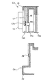
これらの固定用金具15A,15Bは、図1、図2および図4(固定用金具15Aのみ図示)に示すように脚部16を有しており、これら脚部16が回路基板Pに半田付けされることにより回路基板Pに対してハウジング10が固定されている。
These
各固定用金具15A,15Bには、フック17a(係止部)を前端に具備し、かつハウジング10(嵌合用凹部10a)内でその幅方向に撓み変位可能な係止片17(撓み片;図4参照)がそれぞれ一体に形成されており、コネクタ嵌合時にはこの係止片17が配線材側コネクタC1の後記ハウジング20に係合することによって両コネクタを嵌合状態にロックするように構成されている。つまり、これら固定用金具15A,15Bがコネクタのロック機能を兼ね備えた構成となっている。
Each
なお、固定用金具15A,15Bの各係止片17は、図2に示すように上下にオフセットされている。これはハウジング10内に各固定用金具15A,15Bをコンパクトに収めるための工夫であり、これにより後述するように基板側コネクタC2の幅方向の省スペース化が達成されている。
Note that the
一方、配線材側コネクタC1は、図1および図5に示すように幅方向に細長のコネクタハウジング20(以下、ハウジング20と略す)を有している。このハウジング20には、複数の端子収納室22が幅方向に並列に、かつ上下二段に設けられており、ディスクリート線3の先端に装着された端子5が各端子収納室22に収納されている。
On the other hand, the wiring member side connector C1 includes a
端子収納室22は、上下のものが幅方向に半ピッチずれた状態で交互に設けられており、これにより基板側コネクタC2の前記ハウジング10と同様にハウジング全体として端子収納室22が千鳥状の配列となっている。
The
ハウジング20の前側、すなわちコネクタ接続方向の前端面には、上下の端子収納室22の並びに対応して一対の舌片状の端子支持部24が突設されている。
On the front side of the
これらの端子支持部24は、各端子収納室22に収納される端子5の後記接触片5bを支持するもので、各端子支持部24の上面側には、図5および図6に示すようにそれぞれ上向きに開き、かつ端子収納室22内と連通する複数の支持溝26が幅方向に並設されている。また、各支持溝26の前端壁26aには、端子5の接触片5bの浮き上がりを防止するための突起27が後向き(図6では左向き)に突設されている。
These
ディスクリート線3は、例えば撚線の外周に被覆(絶縁層)が形成された単線で、上述のようにその先端には端子5が装着されている。
The
端子5は、図7(a)に示すように、ディスクリート線3を保持するための電線保持部5aとその先端側に設けられるタブ状の接触片5bとを備えた雄型端子である。
As shown in FIG. 7A, the
電線保持部5aには、端子5の底板30の両側に立ち上がる一対のワイヤーバレル32と一対のインシュレーションバレル34とが前後に並べて設けられている。
The electric
接触片5bは、前記底板30に連続して前後方向に延びる連結部37と、その両側から立ち上がって前記各バレル32,34にそれぞれ並ぶ前後方向に細長の互いに平行な一対の単位接触片36a,36bとを備えた断面コ字型の形状に形成されている。また、各単位接触片36a,36bの外側であって、その基端部には端子5を前記ハウジング20に係止するためのフック38が一体形成されている。
The
ディスクリート線3への端子5の装着は、同図に示すようにディスクリート線3の末端部分において被覆が除去されることにより導体3aが外部露出され、この導体3aの部分に対してワイヤーバレル32が、その後側の被覆部分にインシュレーションバレル34がそれぞれ圧着されることにより行われている。ここで、ワイヤーバレル32については、導通性能および保持力を確保するためにワイヤーバレル32の先端が導体3aに食い込むように強固に圧着されている(加締られている)。一方、インシュレーションバレル34は、その先端同士が向かい合うように被覆部分の外側からディスクリート線3を抱え込ませ、その圧着部分が扁平になるように圧着されている。具体的には、図8(a)に示すように、クリンプハイトh(圧着成型高さ)よりもクリンプワイドw(圧着成型幅)が十分に大きくなり、かつクリンプハイトhがディスクリート線3の直径d(図8(b)参照)よりも小さくなるようにディスクリート線3に対してインシュレーションバレル34が圧着されている。これによりディスクリート線3を含む電線保持部5aの全体が扁平にされている。
As shown in the figure, the
そして、このようにディスクリート線3の先端に装着された端子5が各端子収納室22に収納されている。端子収納室22への端子5の収納は、図7(b)に示すように端子5を横向き、すなわち図1および図6に示すようにインシュレーションバレル34のクリンプハイトhの方向が端子収納室22の並び方向(幅方向)に向くように端子5を横向きにし、この状態で端子5をハウジング20の後方から端子収納室22に挿入することにより行われている。詳細には、端子5を端子収納室22に挿入しつつその先端(接触片5b)を端子収納室22から前方に突出させて端子支持部24の支持溝26に介挿し、さらに接触片5bの先端が支持溝26の前端壁26aに当接する位置まで端子5をハウジング20に対して差込む。このようにすると、図6(b)に示すように、支持溝26の前端壁26aに形成された突起27が接触片5bの両単位接触片36a,36bの間に挿入されるとともに、各単位接触片36a,36bに形成されたフック38が端子収納室22の出口(前方側開口)縁部に係合する。これによって端子5のうち接触片5bが外部露出され、かつ突起27により接触片5bの先端が上下方向に拘束された状態で、端子5がディスクリート線3と共にハウジング20に収納、保持される。
The
なお、このハウジング20の端子収納室22は、ほぼ上下、左右が対称な断面形状となっており、端子5が左右何れの向き、つまり端子5におけるディスクリート線3の保持面側が端子収納室22(支持溝26)の並び方向の一方側又は他方側(図9、図10では左側又は右側))の何れを向いた状態でも端子5を挿着し得るようになっている。また、端子支持部24も、同図に示すように、端子収納室22に対して端子5が上記の何れの向きで挿入された場合でも接触片5bの上下方向の変位を適切に拘束して、単位接触片36a,36bのうち上側に位置するもの高さ位置を一定に保ち得るように突起27等が形成されている。つまり、これによって何れの向きで端子5が挿着された場合でも、単位接触片36a,36bの何れか一方に対して相手側の端子12が確実に接触し得るようになっている。
The
なお、ハウジング20の幅方向両端には、図1および図5に示すようにその側面に、基板側コネクタC2の前記係止片17に対応する係止部28が一体形成されている。
As shown in FIGS. 1 and 5, locking
上記のようなコネクタC1、C2の構成において、両コネクタC1、C2を結合させてディスクリート線3を回路基板Pに接続するには、図11(a),図12(a)に示すように、配線材側コネクタC1を基板側コネクタC2の前記嵌合用凹部10aに対向させ、配線材側コネクタC1の両端子支持部24の部分をその先端側から嵌合用凹部10aに差し込む。より詳しくは、基板側コネクタC2に収納された上下二段の端子12のうち、上段の端子12の接続用撓み片14aと支持部14bとの間に配線材側コネクタC1の上側の端子支持部24を、同じく下段の端子12の接続用撓み片14aと支持部14bとの間に配線材側コネクタC1の下側の端子支持部24を差し込みながら両コネクタC1,C2のハウジング同士を嵌合させる。このようにすると、ハウジング20が差し込まれるに伴い基板側コネクタC2の前記係止片17が撓むことにより外側に押し広げられ、両コネクタC1,C2が完全な嵌合状態となると、図12(b)に示すように係止片17が撓み状態から弾性復帰してフック17aがハウジング20の係止部28に係合し、その結果、両コネクタC1,C2が嵌合状態にロックされる。そして、このようにコネクタC1,C2が完全な嵌合状態となると、図11(b)に示すように、各ディスクリート線3に装着された端子5の接触片5bに対して相手側端子12の接続用撓み片14aがそれぞれ接触し、正確には単位接触片36a,36bのうち上側に位置する単位接触片36a(又は36b)に対して相手側端子12の接続用撓み片14aがそれぞれ接触し、この接触により、各ディスクリート線3がそれぞれ対応する相手側端子12を介して回路基板Pの回路に接続されることとなる。
In the configuration of the connectors C1 and C2 as described above, in order to connect both the connectors C1 and C2 and connect the
以上のようなコネクタによると、基板側コネクタC2に関して上記のように固定用金具15A,15Bにフック17aを設け、このフック17aを相手側コネクタC2のハウジング20に係合させることによりコネクタC1,C2を嵌合状態にロックするように構成しているので、すなわち固定用金具15A,15Bにコネクタのロック機能を持たせた構成となっているので、基板側コネクタC2のハウジング10自体に嵌合ロック用の係止部を設ける必要が無い。そのため、ハウジング自体に係止部を設ける従来のこの種のコネクタのように成型金型との関係でハウジングの設計や製作が複雑になることがなく、従って、コネクタ全体としての小型化を図る一方で、従来に比べて嵌合ロック用のフック17aを簡易に設けることが可能となる。しかも、フック17aが金属から形成されて強度的に有利な構成となるため、フック17aの変形等の発生を有効に防止することができ、その結果、両コネクタC1,C2のロック強度を適切に確保することができる。
According to the connector as described above, the
また、固定用金具15A,15Bに設けられた幅方向に撓み変位可能な係止片17(撓み片)にフック17aが一体に形成されており、コネクタ嵌合時には、係止片17が配線材側コネクタC1(ハウジング20)の基板側コネクタC2(ハウジング10)への差込みに伴い外側に撓み(図12(b)の二点鎖線参照)、両ハウジング10,20が完全な嵌合状態となると弾性復帰してフック17aが相手側ハウジング20に係合するように構成されているため、コネクタC1,C2の嵌合作業性が向上するという効果もある。つまり、ハウジング10,20同士が完全な嵌合状態となって係止片17が撓み状態から復帰する際には、当該係止片17がハウジング20側面を叩く(衝突する)こととなるため、作業者はその感覚を衝突音、あるいは振動(衝突感)により感知することができる。特に、係止片17が金属からなり弾発力が強く、上記の振動や衝突音は大きいものとなるため、作業者は両ハウジング10,20が完全な嵌合状態になったこと、すなわちロックフィーリングを良好に得ることができ、その結果、コネクタC1,C2の嵌合作業を適切、かつ速やかに行うことができるようになる。
In addition, a
また、上記の基板側コネクタC2では、固定用金具15A,15Bにそれぞれ係止片17を設け、これら係止片17を配線材側コネクタC1のハウジング20に係合させるように構成しているが、当実施形態では、図2に示すように各係止片17が上下にオフセットされている結果、基板側コネクタC2の小型化が達成されるという効果もある。
In the board-side connector C2, the fixing
詳しく説明すると、この基板側コネクタC2では、同図に示すように上段の端子収納室13の並びが下段の端子収納室13の並びに対して左側に半ピッチずれた配列となっており、このずれに応じて左側の固定用金具15Aでは下段の端子収納室13の並びに係止片17を設ける一方、右側の固定用金具15Bでは上段の端子収納室13の並びに係止片17を設けた構成となっている。換言すれば、上下各段の並びの最端に位置する端子12のうち、ハウジング10の幅方向(左右)中央寄りに配設される端子12に係止片17が並ぶように各固定用金具15A,15Bに係止片17が設けられている。つまり、上下各段の端子収納室13が左右方向ずれている結果、上段の端子収納室13の並びではハウジング10の右方端部に、下段の端子収納室13の並びではハウジング10の左方端部にそれぞれデッドスペースができる。そこで、この配線材側コネクタC1では、このデッドスペースに係止片17が位置するように各固定用金具15A,15Bに係止片17を設けることによって、係止片17の撓み代を十分に確保しつつ両固定用金具15A,15Bをハウジング10内にコンパクトに収納している。従って、この点で基板側コネクタC2の小型化が達成されるという効果もある。
More specifically, in this board-side connector C2, as shown in the figure, the arrangement of the upper
なお、上記実施形態のコネクタC1,C2によると、さらに次ぎのような特徴もある。 In addition, according to the connectors C1 and C2 of the said embodiment, there also exist the following characteristics.
すなわち、配線材側コネクタC1における端子5の保持構造に関し、上記のようにインシュレーションバレル34のクリンプハイトhがクリンプワイドwよりも小さい(ディスクリート線3の直径dよりも小さい)扁平状態となるように端子5をディスクリート線3に装着し、さらにインシュレーションバレル34のクリンプハイトhが端子収納室22の並び方向に向くように端子5を横向きにした状態でハウジング20に収納するように構成しているので、換言すればインシュレーションバレル34のクリンプハイトhの方向に端子5を並べた状態でハウジング20に対して該端子5を収納するように配線材側コネクタC1を構成しているので、端子5の配列を効果的に狭ピッチ化することができ、その結果、複雑な端子構造を採ることなくフラット配線材6の導体6aと等ピッチで端子5をハウジング20に収納できる。すなわち、従来では、端子のインシュレーションバレルはディスクリート線の断面形状をほぼ維持しつつその被覆外側から抱え込むように圧着されており、そのため端子間ピッチの設定に際してはインシュレーションバレルのクリンプワイドによる制約を受け易く狭ピッチ化が難しい。これに対して、上記のように配線材側コネクタC1の構成によると、インシュレーションバレル34のクリンプハイトhの方向に端子5を並べるため端子間ピッチの設定に際してクリンプワイドwによる制約を受けることがなく、しかも、クリンプハイトhがクリンプワイドwよりも小さくなる扁平な状態でディスクリート線3に対してインシュレーションバレル34が圧着されているため、端子配列方向の占有スペースが効果的に縮小され、その結果、端子配列の狭ピッチ化が達成される。従って、複雑な端子構造を採ることなく端子5をフラット配線材6の導体6aと等ピッチで配列した状態でハウジング20内に収納できる。
That is, regarding the holding structure of the
ところで、以上説明したコネクタの上記基板側コネクタC2は、本発明に係る基板実装型コネクタの実施形態の一例であって、その具体的な構成は本発明の要旨を逸脱しない範囲で適宜変更可能である。例えば、コネクタC1,C2を嵌合ロックする構造として以下に図13〜図17を用いて説明する第1、第2変形例のような構成を採用することもできる。なお、これらの変形例も基本的な構成は実施形態のものと共通するため、共通する部分については同一符号を付してその説明を省略し、相違点についてのみ詳細に説明することとする。 By the way, the board-side connector C2 of the connector described above is an example of an embodiment of the board-mounted connector according to the present invention, and its specific configuration can be appropriately changed without departing from the gist of the present invention. is there. For example, as the structure for fitting and locking the connectors C1 and C2, configurations such as first and second modifications described below with reference to FIGS. 13 to 17 can be employed. In addition, since these modification examples also have the same basic configuration as that of the embodiment, common parts are denoted by the same reference numerals, description thereof is omitted, and only differences are described in detail.
〈 第1変形例 〉
図13は、固定用金具15A,15B(一方側の固定用金具15Aのみ図示)を示す図で、図14は配線材側コネクタC1および基板側コネクタC2の要部断面図である。
<First Modification>
FIG. 13 is a view showing the fixing
これら図13,図14に示すように、第1変形例の固定用金具15Aには、ハウジング10(嵌合用凹部10a)内において係止片17よりも内側、つまり端子12に近い側(図14では右側)にこの係止片17と平行に並ぶ当接板18(当接部分)が設けられている。
As shown in FIGS. 13 and 14, the fixing
この当接板18には切欠部分18aが形成されており、係止片17の前記フック17aの先端部分がこの切欠部分18aから突出して嵌合用凹部10a内に臨んでいる。
The
係止片17の先端部分(図14では下端部分)とこれに対応する当接板18の部分には、エンボス加工が施されることにより互いに相手側に向って突出する部分(以下、エンボス部17b,18bという)が形成されており、これらエンボス部17b,18b(突出部)が係止片17の撓み方向に互いに当接するようになっている。
The front end portion (lower end portion in FIG. 14) of the locking
このような第1変形例の構成によると、図14に示すように、配線材側コネクタC1を基板側コネクタC2の前記嵌合用凹部10aに対向させ、配線材側コネクタC1の両端子支持部24の部分をその先端側から嵌合用凹部10aに差し込むと、図15(a)に示すように、ハウジング20が差し込まれるに伴いその係止部28により基板側コネクタC2の係止片17が外側に押し広げられる。そして、両コネクタC1,C2が完全な嵌合状態となると、図15(b)に示すように係止片17が撓み状態から弾性復帰してフック17aがハウジング20の係止部28に係合し、その結果、両コネクタC1,C2が嵌合状態にロックされることとなる。この際、この第1変形例では、係止片17が撓み状態から復帰するときに、金属同士(係止片17,当接板18)が衝突し、しかもその衝突部分にはエンボス加工(エンボス部17b,18b)が施されていることによりクリアーな衝突音が発生することとなる。そのため、係止片17をハウジング20に衝突させる上記実施形態の構成に比べるとより良好なロックフィーリングを得ることが可能となり、その結果、コネクタの嵌合作業性をより一層向上させることができるという効果がある。
According to the configuration of the first modified example, as shown in FIG. 14, the wiring material side connector C1 is opposed to the fitting
この構成では、係止片17および当接板18の互いの当接部位にそれぞれエンボス部(17b,18b)を設けているが、何れか一方側にのみエンボス部を設けるようにしてもよい。また、係止片17と当接板18とを互いに平面同士で衝突させるとが可能で、かつこの衝突により十分なロックフィーリング(音や振動)を得ることができる場合には、エンボス部を省略して固定用金具15A,15Bの構成を簡略化しても構わない。
In this configuration, the embossed portions (17b, 18b) are provided at the contact portions of the locking
なお、図13〜図15では、基板側コネクタC2のハウジング10内に収容される固定用金具15A,15Bのうち一方側(固定用金具15A)のみ図示しているが、他方側(固定用金具15B)も同様の構成となっている。
13 to 15, only one side (fixing
〈 第2変形例 〉
図16,図17は、第2変形例に係る配線材側コネクタC1および基板側コネクタC2の要部、具体的にはコネクタC1,C2を嵌合ロックする部分の構成を示しており、図16は当該部分を斜視図で模式的に示しており、また図17は、当該部分を断面図で示している。
<Second modification>
FIGS. 16 and 17 show the configuration of the main parts of the wiring material side connector C1 and the board side connector C2 according to the second modification, specifically, the portion for fitting and locking the connectors C1 and C2. FIG. 17 schematically shows the part in a perspective view, and FIG. 17 shows the part in a sectional view.
これらの図に示す第2変形例では、基板側コネクタC2における固定用金具15Aの係止片17がハウジング10(嵌合用凹部10a)内において上下方向に撓み可能に設けられており、コネクタC1,C2の未結合状態では、係止片17の先端上面部分がハウジング10(嵌合用凹部10a)内に形成された当たり10b(当接部分)に当接するように構成されている。
In the second modification shown in these drawings, the locking
一方、配線材側コネクタC1は、ハウジング20の前記係止部28(被係止部)が同図に示すような三角柱状に形成されている。詳しくは、ハウジング20の幅方向外側に突出し、かつその下面にコネクタ接続方向前側から後側(図17では右側から左側)に向って先下がりに傾斜する案内面28aを備えた三角柱状に形成されている。
On the other hand, in the wiring member side connector C1, the locking portion 28 (locked portion) of the
このような構成において、配線材側コネクタC1を基板側コネクタC2の前記嵌合用凹部10aに対向させ、配線材側コネクタC1を嵌合用凹部10aに差し込むと、この差込みに伴い、係止部28の案内面28aに沿って基板側コネクタC2の係止片17(フック17a)が押し下げられて図17中に矢印で示すように下方に撓み、両コネクタC1,C2が完全な嵌合状態となると、同図中に二点鎖線に示すように係止部28がフック17aの部分を通過して係止片17が撓み状態から復帰し、その結果、フック17aがハウジング20の係止部28に係合して両コネクタC1,C2が嵌合状態にロックされることとなる。この際、この第2変形例では、係止片17が撓み状態から復帰するときに係止片17がハウジング10の前記当たり10bに衝突して衝突音を発するとともに軽い振動が生じることとなる。つまり、この第2変形例の構成においてもコネクタC1,C2が完全な嵌合状態となったことをこの衝突音や振動に基づいて容易に感知することができる。従って、作業者に対して効果的なロックフィーリングを与えることが可能となり、第1変形例と同様にコネクタの嵌合作業性を向上させることができるという効果がある。特に、この第2変形例の構成では、内外に嵌合するハウジング10、20のうち外側のハウジング10(当たり10b)に対して係止片17が当接するため、音や振動(衝突感)をより作業者が感じ易くなり、良好なロックフィーリングを与えることができるという特徴がある。
In such a configuration, when the wiring material side connector C1 is opposed to the fitting
なお、上記実施形態では、基板側コネクタC2の固定用金具15A,15Bに撓み可能な撓み片(係止片17)を設け、これにフック17aを設けた構成となっているが、例えば固定用金具15A,15Bにはフック17aのみを設ける一方、相手側コネクタ(配線材側コネクタC1)に撓み片を設け、この撓み片に係止部28を設けるように構成してもよい。
In the above embodiment, the fixing
また、上述した実施形態では、ディスクリート線3を回路基板Pに接続する場合の基板側コネクタC2の構成として本発明を適用しているが、勿論、平角導体を並設したフラットケーブル、リボン電線、FPC(Flexible Printed Circuit)等のフラット配線材を回路基板Pに接続する場合の基板側コネクタの構成として本発明を適用することができることは言うまでもない。
In the above-described embodiment, the present invention is applied as the configuration of the board-side connector C2 when the
C1 配線材側コネクタ
C2 基板側コネクタ
P 回路基板
3 ディスクリート線
5,12 端子
10,20 コネクタハウジング
15A,15B 固定用金具
17 係止片
17a フック
28 係止部
C1 Wiring material side connector C2 Board side connector
Claims (2)
前記固定用金具に、当該コネクタに嵌合する相手側コネクタのハウジングに係合して両コネクタを嵌合ロック状態に係止する係止部を備えた撓み片とこの撓み片が当接可能な当接部分とが設けられており、
前記撓み片は、前記両コネクタを互いに嵌合させるとこれに伴い相手側ハウジングに押されて撓み変位し、両コネクタが完全な嵌合状態となると弾性復帰して前記係止部が相手側コネクタのハウジングに係合するように形成され、
前記当接部分は、前記撓み片に対向しかつ前記撓み片が撓み状態から復帰する際に当該撓み片が当接するように形成されていることを特徴とする基板実装型コネクタ。 A resin housing that holds a plurality of terminals connected to the circuit board in a state of being arranged in parallel, and is fixed to both ends of the housing in the width direction, which is the arrangement direction of the terminals, and is mounted on the circuit board In board-mounted connectors with fixing brackets
The bending piece can be brought into contact with the bending piece provided with a locking portion that engages with the housing of the mating connector to be fitted to the connector and locks both the connectors in the fitting locked state. A contact portion is provided ,
When the two connectors are mated with each other, the flexure piece is pushed and displaced by the mating housing, and when the two connectors are in a completely fitted state, the flexure piece is elastically restored and the locking portion is mated with the mating connector. Formed to engage the housing of the
The board-mounted connector , wherein the abutting portion is formed to face the deflecting piece and to abut the deflecting piece when the deflecting piece returns from the bent state .
前記当接部分およびこの当接部分に当接する撓み片の部位の少なくとも一方側に、他方側に向って突出する突出部が設けられていることを特徴とする基板実装型コネクタ。
The board-mounted connector according to claim 1,
It said abutment portion and on at least one side of the site of contact with the deflection piece to the contact portion, the substrate mount type connector, wherein the projecting portion is found provided that protrudes toward the other side.
Priority Applications (4)
| Application Number | Priority Date | Filing Date | Title |
|---|---|---|---|
| JP2004212627A JP4425732B2 (en) | 2004-07-21 | 2004-07-21 | Board mounted connector |
| DE102005033973A DE102005033973B4 (en) | 2004-07-21 | 2005-07-20 | Board-mounted type connector |
| US11/185,869 US7258567B2 (en) | 2004-07-21 | 2005-07-21 | Board mounting type connector with metal fastening member |
| CNB2005100859745A CN100541931C (en) | 2004-07-21 | 2005-07-21 | Board mounting type connector |
Applications Claiming Priority (1)
| Application Number | Priority Date | Filing Date | Title |
|---|---|---|---|
| JP2004212627A JP4425732B2 (en) | 2004-07-21 | 2004-07-21 | Board mounted connector |
Publications (2)
| Publication Number | Publication Date |
|---|---|
| JP2006032250A JP2006032250A (en) | 2006-02-02 |
| JP4425732B2 true JP4425732B2 (en) | 2010-03-03 |
Family
ID=35657814
Family Applications (1)
| Application Number | Title | Priority Date | Filing Date |
|---|---|---|---|
| JP2004212627A Expired - Fee Related JP4425732B2 (en) | 2004-07-21 | 2004-07-21 | Board mounted connector |
Country Status (4)
| Country | Link |
|---|---|
| US (1) | US7258567B2 (en) |
| JP (1) | JP4425732B2 (en) |
| CN (1) | CN100541931C (en) |
| DE (1) | DE102005033973B4 (en) |
Families Citing this family (19)
| Publication number | Priority date | Publication date | Assignee | Title |
|---|---|---|---|---|
| CN101227033B (en) * | 2007-01-17 | 2010-06-16 | 富士康(昆山)电脑接插件有限公司 | Electric connector |
| CN102237612B (en) * | 2010-03-31 | 2014-12-03 | 广濑电机株式会社 | Electric connector for circuit substrate |
| JP5906579B2 (en) * | 2011-04-08 | 2016-04-20 | セイコーエプソン株式会社 | Terminal module and recording device |
| JP5765027B2 (en) * | 2011-04-08 | 2015-08-19 | セイコーエプソン株式会社 | RECORDING DEVICE AND TERMINAL MODULE FOR RECORDING DEVICE |
| JP5826565B2 (en) * | 2011-08-31 | 2015-12-02 | 日本航空電子工業株式会社 | connector |
| JP5741335B2 (en) * | 2011-09-10 | 2015-07-01 | 住友電装株式会社 | Board connector |
| KR101996106B1 (en) | 2011-11-15 | 2019-07-03 | 티코나 엘엘씨 | Low naphthenic liquid crystalline polymer composition for use in molded parts of a small dimensional tolerance |
| TWI534253B (en) | 2011-11-15 | 2016-05-21 | 堤康那責任有限公司 | Naphthenic-rich liquid crystalline polymer composition with improved flammability performance |
| JP2014533325A (en) | 2011-11-15 | 2014-12-11 | ティコナ・エルエルシー | Low naphthenic liquid crystal polymer composition |
| WO2013074470A2 (en) | 2011-11-15 | 2013-05-23 | Ticona Llc | Fine pitch electrical connector and a thermoplastic composition for use therein |
| US8646994B2 (en) | 2011-11-15 | 2014-02-11 | Ticona Llc | Compact camera module |
| JP6058355B2 (en) * | 2012-07-19 | 2017-01-11 | 日本航空電子工業株式会社 | connector |
| JP5814411B2 (en) * | 2014-03-20 | 2015-11-17 | イリソ電子工業株式会社 | connector |
| JP2017191674A (en) * | 2016-04-12 | 2017-10-19 | 住友電装株式会社 | Board connector |
| JP6638583B2 (en) * | 2016-07-12 | 2020-01-29 | 株式会社オートネットワーク技術研究所 | Connector and electric connection assembly having the same |
| JP2019087462A (en) * | 2017-11-08 | 2019-06-06 | ケル株式会社 | Connector device |
| CN109921213B (en) * | 2017-12-13 | 2021-06-22 | 唐虞企业股份有限公司 | Electric connector assembly and plate end connector and wire end connector thereof |
| JP7182064B2 (en) * | 2019-06-17 | 2022-12-02 | 株式会社オートネットワーク技術研究所 | connector |
| US11509082B2 (en) * | 2020-06-11 | 2022-11-22 | Molex, Llc | Circuit board cable connector with more than one mounting configuration |
Family Cites Families (9)
| Publication number | Priority date | Publication date | Assignee | Title |
|---|---|---|---|---|
| JP2752024B2 (en) | 1992-03-25 | 1998-05-18 | 矢崎総業株式会社 | Printed circuit board connector |
| US5533908A (en) * | 1994-08-31 | 1996-07-09 | The Whitaker Corporation | Latch and mounting member for a surface mounted electrical connector |
| US5478253A (en) * | 1994-09-21 | 1995-12-26 | The Whitaker Corporation | Electrostatic discharge contacts for blind mating connectors |
| US5759057A (en) * | 1996-04-03 | 1998-06-02 | Hon Hai Precision Ind. Co., Ltd. | Connector with hybrid latch device |
| DE19621614C1 (en) * | 1996-05-30 | 1997-12-18 | Itt Cannon Gmbh | Connectors |
| JP2003168519A (en) * | 2001-11-30 | 2003-06-13 | Japan Aviation Electronics Industry Ltd | Connector |
| TW558098U (en) * | 2002-11-15 | 2003-10-11 | Hon Hai Prec Ind Co Ltd | An electrical connector |
| US6692273B1 (en) * | 2002-12-31 | 2004-02-17 | Hon Hai Precision Ind. Co., Ltd. | Straddle mount connector |
| JP2004288494A (en) * | 2003-03-24 | 2004-10-14 | Hirose Electric Co Ltd | Connector |
-
2004
- 2004-07-21 JP JP2004212627A patent/JP4425732B2/en not_active Expired - Fee Related
-
2005
- 2005-07-20 DE DE102005033973A patent/DE102005033973B4/en not_active Expired - Fee Related
- 2005-07-21 US US11/185,869 patent/US7258567B2/en not_active Expired - Fee Related
- 2005-07-21 CN CNB2005100859745A patent/CN100541931C/en not_active Expired - Fee Related
Also Published As
| Publication number | Publication date |
|---|---|
| JP2006032250A (en) | 2006-02-02 |
| US7258567B2 (en) | 2007-08-21 |
| DE102005033973A1 (en) | 2006-02-23 |
| US20060019511A1 (en) | 2006-01-26 |
| CN100541931C (en) | 2009-09-16 |
| DE102005033973B4 (en) | 2009-06-10 |
| CN1750328A (en) | 2006-03-22 |
Similar Documents
| Publication | Publication Date | Title |
|---|---|---|
| JP4425732B2 (en) | Board mounted connector | |
| JP4970981B2 (en) | Electrical connector | |
| US7422465B2 (en) | Electrical connector having flexible mating portion | |
| JP4493710B2 (en) | Electrical connector | |
| KR101157672B1 (en) | Connector | |
| JP2009517802A (en) | Electrical connector | |
| JP2007128876A (en) | Electric connector | |
| JP2939867B2 (en) | Electrical connector with metal outer wall structure | |
| JP2005196975A (en) | Connector | |
| US20220224046A1 (en) | Connector and connector device | |
| JP7298461B2 (en) | Female terminals and female connectors | |
| US6739903B1 (en) | Connector structure | |
| JP4353433B2 (en) | connector | |
| JP4876012B2 (en) | Plug-in connector | |
| JP2761832B2 (en) | Connection terminal locking structure | |
| JP4314106B2 (en) | Female terminal | |
| JP3246894B2 (en) | connector | |
| JP4391336B2 (en) | connector | |
| JP4401877B2 (en) | connector | |
| EP1804344A2 (en) | Electrical connector having flexible mating portion | |
| JP3141905U (en) | connector | |
| JP2005123100A (en) | Joint connector | |
| JP2005317357A (en) | Board-mounted connector and board-mounted connector with case | |
| JP3435009B2 (en) | Electrical junction box | |
| JP2005166408A (en) | Joint connector |
Legal Events
| Date | Code | Title | Description |
|---|---|---|---|
| A621 | Written request for application examination |
Free format text: JAPANESE INTERMEDIATE CODE: A621 Effective date: 20070622 |
|
| A977 | Report on retrieval |
Free format text: JAPANESE INTERMEDIATE CODE: A971007 Effective date: 20090721 |
|
| A131 | Notification of reasons for refusal |
Free format text: JAPANESE INTERMEDIATE CODE: A131 Effective date: 20090811 |
|
| A521 | Written amendment |
Free format text: JAPANESE INTERMEDIATE CODE: A523 Effective date: 20091009 |
|
| TRDD | Decision of grant or rejection written | ||
| A01 | Written decision to grant a patent or to grant a registration (utility model) |
Free format text: JAPANESE INTERMEDIATE CODE: A01 Effective date: 20091208 |
|
| A01 | Written decision to grant a patent or to grant a registration (utility model) |
Free format text: JAPANESE INTERMEDIATE CODE: A01 |
|
| A61 | First payment of annual fees (during grant procedure) |
Free format text: JAPANESE INTERMEDIATE CODE: A61 Effective date: 20091209 |
|
| R150 | Certificate of patent or registration of utility model |
Free format text: JAPANESE INTERMEDIATE CODE: R150 |
|
| FPAY | Renewal fee payment (event date is renewal date of database) |
Free format text: PAYMENT UNTIL: 20121218 Year of fee payment: 3 |
|
| FPAY | Renewal fee payment (event date is renewal date of database) |
Free format text: PAYMENT UNTIL: 20131218 Year of fee payment: 4 |
|
| LAPS | Cancellation because of no payment of annual fees |