JP4423932B2 - Nakadome and watch - Google Patents
Nakadome and watch Download PDFInfo
- Publication number
- JP4423932B2 JP4423932B2 JP2003380221A JP2003380221A JP4423932B2 JP 4423932 B2 JP4423932 B2 JP 4423932B2 JP 2003380221 A JP2003380221 A JP 2003380221A JP 2003380221 A JP2003380221 A JP 2003380221A JP 4423932 B2 JP4423932 B2 JP 4423932B2
- Authority
- JP
- Japan
- Prior art keywords
- slide member
- hook
- front cover
- band
- plate
- Prior art date
- Legal status (The legal status is an assumption and is not a legal conclusion. Google has not performed a legal analysis and makes no representation as to the accuracy of the status listed.)
- Expired - Fee Related
Links
Images


Landscapes
- Buckles (AREA)
Description
本発明は、例えば、腕時計用バンドやブレスレット等の帯状装身具の中留およびそれを用いた腕時計に関する。 The present invention relates to a strap of a band-shaped accessory such as a wristwatch band or a bracelet and a wristwatch using the same.
一般に、表カバーと中板と下板とを有し、表カバーにはばね棒を介して当該表カバーの内側に保持されて、中板もしくは下板に形成されたフックと係合する方向に付勢されるスライド部材を備え、表カバーの外側に突出した操作部を操作することにより、スライド部材をスライドさせて、当該スライド部材と中板もしくは下板に形成されたフックとの係合を解除する三つ折れ中留が知られている(例えば、特許文献1参照)。
しかし、従来の構成では、錠止ピンと摺動錠止板とを係合させて、スライド部材と中板もしくは下板に形成されたフックとを係合させているため、錠止ピンの先端部が摺動錠止板の上面より上方に飛び出ることとなり、中留の表カバーの上面から下板までの厚さを薄くすることが困難になるという問題がある。また、錠止部材をバンド長さ方向にスライドさせるため、上部枠体には錠止部材の厚さより若干高い立ち上り部が必要となり、さらに、錠止ピンの先端部を収めるための凸部が形成されているため、中留の表カバーの上面から下板までの厚さを薄くすることが困難になるという問題がある。
そこで、本発明の目的は、上述した従来の技術が有する課題を解消し、薄型腕時計に適用可能な薄型の中留及び腕時計を提供することにある。
However, in the conventional configuration, the locking pin and the sliding locking plate are engaged, and the slide member and the hook formed on the middle plate or the lower plate are engaged. Protrudes upward from the upper surface of the sliding lock plate, and there is a problem that it is difficult to reduce the thickness from the upper surface of the middle cover front cover to the lower plate. In addition, in order to slide the locking member in the band length direction, the upper frame requires a rising part slightly higher than the thickness of the locking member, and further, a convex part is formed to accommodate the tip of the locking pin. Therefore, there is a problem that it is difficult to reduce the thickness from the upper surface of the front cover of the Nakadome to the lower plate.
SUMMARY OF THE INVENTION An object of the present invention is to solve the above-described problems of the prior art and to provide a thin brace and wristwatch applicable to a thin wristwatch.
本発明は、表カバーと中板と下板とを有し、前記表カバーにはばね棒を介して当該表カバーの内側に保持されて、前記中板もしくは前記下板に形成されたフックと係合する方向に付勢されるスライド部材を備え、前記表カバーの外側に突出した操作部を操作することにより、スライド部材をスライドさせて、当該スライド部材と前記中板もしくは前記下板に形成されたフックとの係合を解除する中留において、前記スライド部材が平板状に形成され、その平板部には前記フックと係合する係合部と、前記ばね棒が貫通する長孔を有する保持部とが形成されていることを特徴とする。
また、この場合において、前記スライド部材における前記保持部の間に前記係合部が形成されていてもよい。
またさらに、前記スライド部材と前記操作部とが平板状の素材をプレス加工することにより一体的に形成されていてもよい。
さらに、操作部の板厚がほかの部分の板厚よりも厚く形成されていてもよい。
フックの高さが保持部の高さよりも低く形成されていてもよい。
スライド部材を付勢する手段がコイルばねであってもよい。
The present invention has a front cover, an intermediate plate, and a lower plate, and the front cover is held inside the front cover via a spring bar, and a hook formed on the intermediate plate or the lower plate; A slide member that is biased in the engaging direction is provided, and the slide member is slid by operating an operation portion that protrudes to the outside of the front cover, and is formed on the slide member and the middle plate or the lower plate. The intermediate member that releases the engagement with the hook is formed in a flat plate shape, and the flat plate portion has an engagement portion that engages with the hook and a long hole through which the spring bar passes. A holding portion is formed.
In this case, the engaging portion may be formed between the holding portions of the slide member.
Furthermore, the slide member and the operation portion may be integrally formed by pressing a flat material.
Furthermore, the plate thickness of the operation portion may be formed thicker than the plate thickness of other portions.
The height of the hook may be lower than the height of the holding portion.
The means for biasing the slide member may be a coil spring.
また、時計ケースと、時計バンドと、この時計バンドの中留とを備え、この中留が、表カバーと中板と下板とを有し、前記表カバーにはばね棒を介して当該表カバーの内側に保持されて、前記中板もしくは前記下板に形成されたフックと係合する方向に付勢されるスライド部材を備え、前記表カバーの外側に突出した操作部を操作することにより、スライド部材をスライドさせて、当該スライド部材と前記中板もしくは前記下板に形成されたフックとの係合を解除するように構成され、前記スライド部材が平板状に形成され、その平板部には前記フックと係合する係合部と、前記ばね棒が貫通する長孔を有する保持部とが形成されていてもよい。
また、この場合において、前記スライド部材における前記保持部の間に前記係合部が形成されていてもよい。
またさらに、前記スライド部材と前記操作部とが平板状の素材をプレス加工することにより一体的に形成されていてもよい。
さらに、操作部の板厚がほかの部分の板厚よりも厚く形成されていてもよい。
フックの高さが保持部の高さよりも低く形成されていてもよい。
スライド部材を付勢する手段がコイルばねであってもよい。
In addition, the watch case includes a watch case, a watch band, and a middle stopper of the watch band, and the middle fastener has a front cover, a middle plate, and a lower plate, and the front cover is attached to the front cover via a spring bar. A slide member that is held inside the cover and is biased in a direction to engage with a hook formed on the middle plate or the lower plate, and by operating an operation portion that protrudes outside the front cover; The slide member is slid to disengage the slide member from the hook formed on the middle plate or the lower plate, and the slide member is formed in a flat plate shape, An engaging portion that engages with the hook and a holding portion having a long hole through which the spring bar passes may be formed.
In this case, the engaging portion may be formed between the holding portions of the slide member.
Furthermore, the slide member and the operation portion may be integrally formed by pressing a flat material.
Furthermore, the plate thickness of the operation portion may be formed thicker than the plate thickness of other portions.
The height of the hook may be lower than the height of the holding portion.
The means for biasing the slide member may be a coil spring.
本発明では、スライド部材が平板状に形成され、その平板部にはフックと係合する係合部と、ばね棒が貫通する長孔を有する保持部とが形成されているため、表カバーの内側にスライド部材をコンパクトに収容することができ、従って、薄型腕時計に適用可能な薄型の中留が提供される。 In the present invention, the slide member is formed in a flat plate shape, and the flat plate portion is formed with an engaging portion that engages with the hook and a holding portion having a long hole through which the spring bar passes. A slide member can be accommodated in a compact manner on the inside, and therefore, a thin middle end applicable to a thin wristwatch is provided.
以下、本発明の一実施形態を、図面に基づき説明する。
図1は、本発明の実施形態に係る腕時計の外観構成を示す図である。この腕時計1は、時刻表示を行う時計本体3と、この時計本体3に連結されたバンド5とから構成される。時計本体3は、例えば、ステンレス、チタン等で形成された金属ケース内に、時計表示部が内蔵されて構成される。
なお、本構成では、時刻をアナログ表示する腕時計を例示したが、時刻をデジタル表示する腕時計であってもよい。
バンド5は、ステンレス、チタン等の金属材料で形成された駒を多数連結して構成される。バンド5は、上バンド5Aと、下バンド5Bとからなり、これら上バンド5Aと、下バンド5Bとは、この腕時計1を装着部位(装着者の手首)に止めるため、中留(結束部)7で結束される。
Hereinafter, an embodiment of the present invention will be described with reference to the drawings.
FIG. 1 is a diagram showing an external configuration of a wristwatch according to an embodiment of the present invention. The
In this configuration, the wristwatch that displays the time in an analog manner is exemplified, but a wristwatch that digitally displays the time may be used.
The
この中留7は、図2又は図4に示すように、上バンド5Aにピン連結された表カバー10と、下バンド5Bにピン連結された中板11と、中板11にピン12で連結された下板13と、表カバー10の内側に収容されたスライド部材21とを備えて構成される。
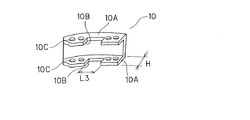
表カバー10には、図5に示すように、その裏側に延びる一対の立上部10Aと、各立上部10Aに形成された開口部10Bと、開口部10Bの両側の立上部10Aに形成された孔10Cとが形成され、この孔10Cの内、最も外側の孔には夫々ピン14を介して上バンド5Aと、下板13とが連結される。また、孔10Cの内、最も内側の孔には夫々ばね棒15が挿入される。夫々のばね棒15は、図4に示すように、スライド部材21の保持部22の長孔23を貫通し、その両端が、各立上部10Aの孔10Cに保持され、スライド部材21を表カバー10の内側に保持する。
As shown in FIG. 2 or FIG. 4, the
As shown in FIG. 5, the
このスライド部材21は、図6に示すように、概ね平板状に形成される。その平板部21Aには、中板11に形成された逆L字形状のフック11A(図2)に係合する係合部21Bと、ばね棒15が貫通する長孔23を有する4つの保持部22と、表カバー10の開口部10Bを通じて、表カバー10の両外側に突出(図2参照)する一対の操作部25とが一体的に形成される。
ここで、フック11Aは、図2に示すように、中板11の一部を切り起こして形成してもよく、或いは、図3A,Bに示すように、別個のフック11Aを中板11に対してねじ11C止めしてもよく、もしくは中板11の裏面側からかしめてもよい。
なお、図示は省略したが、中留7の構造によっては、フック11Aを中板11でなく、下板13に形成する場合がある。この下板13にフックを形成する場合においても、当該フックは同様に構成される。
As shown in FIG. 6, the
Here, the
Although illustration is omitted, depending on the structure of the
スライド部材21の製造手順を説明すると、まず、一枚の平板(平板状の素材)100を、図7に示すように、プレスにより打ち抜き加工する。
ついで、矢印A,Bで示す方向に折り曲げて、破線で示す2つの保持部22A,22Bを形成し、さらに、平板100を重ね合わせるように、矢印C,Dで示す方向に折り曲げて、破線で示す2つの保持部22C,22Dを形成すると共に、一対の操作部(とっ手部)25を形成する。
この場合において、上記係合部21Bは平板100の一部で形成されており、2つの保持部22A,22Bの間に形成されている。
また、操作部25の板厚T1は、例えば、プレスによる圧縮工程を付加することなどによって、ほかの平板100の板厚T2よりも厚くしておくことが望ましい。これによれば、操作部25に手指を添えてスライド部材21をスライドさせる場合、手指に作用する単位面積当たりの力を小さくすることができ、操作性を向上させることができる。
The manufacturing procedure of the
Next, it is bent in the directions indicated by arrows A and B to form two holding
In this case, the engaging
Further, it is desirable that the plate thickness T1 of the
この操作部25は、図6に示すように、平板部21Aとの間に寸法L1をあけて形成される。この寸法L1は、表カバー1の立上部10Aの厚さよりも若干大きく形成され、スライド部材21が表カバー10の内側に装着されるとき、操作部25に連なる首部21Cが、表カバー10の開口部10Bに嵌め込まれる。
また、上記首部21Cの幅寸法L4は、表カバー10の開口部10Bの幅寸法L3よりも小さく設定される。
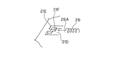
このスライド部材21は、保持部22C,22Dの間に凹部21Dを有し、この凹部21Dの壁面21Eにばね受け21Fを備えて構成される。
そして、スライド部材21が表カバー10の内側に装着されたとき、図4に示すように、ばね受け21Fとばね棒15との間に、コイルばね26が配置され、このコイルばね26により、スライド部材21は、逆L字形状のフック11Aと係合部21Bとが係合する方向(図4の矢印X方向)に付勢される。このコイルばね26の一端26Aは、図8に示すように、ばね受け21Fの外周に嵌って係止される。従って、コイルばね26を安定した状態でセットできる。
As shown in FIG. 6, the operating
Further, the width dimension L4 of the
The
When the
上記構成では、図4に示すように、フック11Aの高さが保持部22の高さよりも低く形成される。このことによって、スライド部材21を収容する表カバー10の高さH(図5)は、この保持部22の高さによって支配される。
本構成では、一枚の平板100を、図7に矢印A,Bで示すように折り曲げ加工することにより保持部22を形成するため、保持部22の高さを比較的低く抑えることができ、この保持部22の高さによって支配される表カバー10の高さHをより低く抑えることができ、表カバー10の小型薄型化が図られる。
In the above configuration, as shown in FIG. 4, the height of the
In this configuration, since the holding
表カバー10へのスライド部材21の組み込みは次の通りである。
図6に示す状態のスライド部材21の保持部22の長孔23にばね棒15を挿通し、ばね受け21Fとばね棒15の間にコイルばね26をセットした後、ばね棒15の先端部のピン(図示せず)を表カバー10の立上部10Aの開口部10B近傍に形成された孔10Cに挿入して、スライド部材21を表カバー10に取り付ける。
この取り付け状態では、コイルばね26が、ばね受け21Fとばね棒15の間にセットされることによって、スライド部材21の全体がばね棒15に対して前方(コイルばね26の長さ方向)に移動した状態で安定した状態となる。
Assembling of the
The
In this attached state, the
操作は次の通りである。
中留7をロックする場合には、表カバー10と、中板11と、下板13とを重ね合わせた後、表カバー10を中板11の方向に押し下げる。
これを押し下げると、まず、スライド部材21の係合部21Bの下面がフック11Aの上面に当接する。ここで、係合部21Bの下面には、図4に示すように、傾斜面30が形成されており、スライド部材21には、この傾斜面30の機能により、コイルばね26のばね力に抗して矢印X方向と逆方向に向かう分力が作用し、この分力により押されてスライド部材21全体がその方向に移動する。スライド部材21全体がその方向に移動すると、係合部21Bとフック11Aのオーバーラップ状態が解除されて、フック11Aの下に係合部21Bが位置すると同時に、図4に示すように、スライド部材21全体が、コイルばね26の弾性力によって元の位置に押し戻され、これによって、係合部21Bの上面部がフック11Aの凹部内に移動してロックされる。
The operation is as follows.
When locking the
When this is pushed down, first, the lower surface of the engaging
中留7のロックを解除する場合には、表カバー10の立上部10Aの外側面から突出する操作部25を掴んで、この操作部25をバンド長さ方向(図4の矢印Xと逆方向。)にスライドさせる。すると、中板11のフック10Aと、スライド部材21の係合部21Bとのかみ合わせが解除され、さらに、表カバー10を中板11と反対方向に回動させると、当該ロックが解除されて、図2の状態となる。
In order to release the lock of the
上記構成では、スライド部材21の操作部25が、図6に示すように、バンド長さ方向に首部21Cよりも突出する凸部25Aを備えて構成される。
この構成では、図2に示すように、この凸部25Aが、表カバー10の開ロ部10Bの長さ方向の隙間を覆うことになる。従って、外から開ロ部10Bが見えることがなく、外観美を損なうことがない。
別の実施形態として、図9に示すように、スライド部材21の首部21Cの下面に、張り出し部31を設けることが可能である。この場合、張り出し部31の突出寸法L2は、表カバー10の立上部10Aの厚さよりも若干小さくする。
これによれば、表カバー10の開口部10Bの厚さ方向の隙間を埋めることができ、外観美を損なうことがない。
In the above configuration, the
In this configuration, as shown in FIG. 2, the
As another embodiment, as shown in FIG. 9, an
According to this, the gap in the thickness direction of the
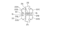
図10は、別の実施形態を示す。
この構成では、バンド幅方向の2つの保持部22A,22B間を連結部22Eで連結すると共に、2つの保持部22C,22D間の凹部21Dを延ばして、当該2つの保持部22C,22D間を完全に分離し、そこにコイルばね26を設け、このコイルばね26を連結部22Eとばね棒15間に保持して構成される。
これによれば、図6に示す場合と比べて、スライド部材21の長さ(バンド長さ方向)をコンパクトにすることができる。
なお、図10において、保持部22A,22B近傍に切り込み33を設けているが、これを設けることによって、図7に示すように平板100を折り曲げて保持部22A,22Bを形成するとき、その折り曲げを容易に行うことができる。
FIG. 10 shows another embodiment.
In this configuration, the two holding
According to this, compared with the case shown in FIG. 6, the length (band length direction) of the
In FIG. 10, the
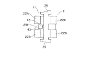
図11及び図12は、別の実施形態を示す。
この構成では、スライド部材41に開口部43が形成され、この開口部43に中板11のフック11Aが嵌り合っている。
そして、開口部43の縁45の下面に傾斜面47が形成されている。この傾斜面47の機能は、上記実施形態の傾斜面30の機能と同じである。これによっても、表カバー10の小型、薄型化が図れる。
11 and 12 show another embodiment.
In this configuration, an
An
図13A〜Cは、さらに別の実施形態を示す。
本構成では、スライド部材21の2つの保持部22C,22D間に、図13Cに示すように、セットされたコイルばね26の上方を覆う張り出し部51が一体に形成される。これによれば、コイルばね26のばね棒15側の端部を安定させることができる。この構成は、例えば、図8の構成と組み合わせてもよい。
13A-C show yet another embodiment.
In this configuration, as illustrated in FIG. 13C, an overhanging
以上、各実施形態によれば、スライド部材21に係合部21Bを直接形成したので、中板11に形成した逆L字型のフック11Aの上面部がスライド部材21の厚さ寸法内に位置することとなり、中留7の総厚を薄くすることができる。
また、スライド部材21に操作部25を一体形成したので、従来のものに比べて、部品点数が少なくなり低コスト化が図られる、等の効果が得られる。
As described above, according to each embodiment, since the engaging
In addition, since the operating
7…中留、10…表カバー、10A…立上部、10B…開口部、11…中板、11A…フック、13…下板、15…ばね棒、21…スライド部材、22…保持部、23…長孔、25…操作部、100…平板。 7 ... Nakadome, 10 ... Front cover, 10A ... Upright part, 10B ... Opening part, 11 ... Middle plate, 11A ... Hook, 13 ... Lower plate, 15 ... Spring bar, 21 ... Slide member, 22 ... Holding part, 23 ... long hole, 25 ... operation part, 100 ... flat plate.
Claims (8)
一方端が前記第1バンドに連結されると共にばね棒を介してスライド部材を可動可能に保持する表カバーと、 A front cover having one end connected to the first band and movably holding a slide member via a spring bar;
前記表カバーの他方端に連結される下板と、 A lower plate connected to the other end of the front cover;
一方端が前記下板に連結されると共に他方端が前記第2バンドに連結される中板を備えた三つ折れの中留において、 In a three-fold middle end with an intermediate plate having one end connected to the lower plate and the other end connected to the second band,
前記中板には前記スライド部材と係合するフックが形成され、 A hook that engages with the slide member is formed on the intermediate plate,
前記スライド部材は平板から形成されると共に前記スライド部材には前記フックと係合する係合部と、前記ばね棒が貫通する長孔の保持部とが前記平板から一体的に形成され、 The slide member is formed of a flat plate, and an engaging portion that engages with the hook and a holding portion of a long hole through which the spring bar penetrates are integrally formed from the flat plate.
さらに前記スライド部材は、前記ばね棒が挿入される前記保持部の長孔方向へ移動して前記フックと係脱可能に前記表カバーに保持され、 Furthermore, the slide member moves in the direction of the long hole of the holding portion into which the spring bar is inserted, and is held by the front cover so as to be detachable from the hook,
前記三つ折れの中留を折りたたんで前記係合部と前記フック部とを係合した状態では、前記フックの高さが前記保持部の上面よりも低いこと In the state in which the engagement portion and the hook portion are engaged by folding the three-fold middle ends, the height of the hook is lower than the upper surface of the holding portion.
を特徴とする中留。Nakadome characterized by.
一方端が前記第1バンドに連結されると共にばね棒を介してスライド部材を可動可能に保持する表カバーと、 A front cover having one end connected to the first band and movably holding a slide member via a spring bar;
前記表カバーの他方端に連結される下板と、 A lower plate connected to the other end of the front cover;
一方端が前記下板に連結されると共に他方端が前記第2バンドに連結される中板と、を有する三つ折れの中留を備えた腕時計において、 In a wristwatch having a three-fold middle clasp having one end connected to the lower plate and the other end connected to the second band,
前記中板には前記スライド部材と係合するフックが形成され、 A hook that engages with the slide member is formed on the intermediate plate,
前記スライド部材は平板から形成されると共に前記スライド部材には前記フックと係合する係合部と、前記ばね棒が貫通する長孔の保持部とが前記平板から一体的に形成され、 The slide member is formed of a flat plate, and an engaging portion that engages with the hook and a holding portion of a long hole through which the spring bar penetrates are integrally formed from the flat plate.
さらに前記スライド部材は、前記ばね棒が挿入される前記保持部の長孔方向へ移動して前記フックと係脱可能に前記表カバーに保持され、 Furthermore, the slide member moves in the direction of the long hole of the holding portion into which the spring bar is inserted, and is held by the front cover so as to be detachable from the hook,
前記三つ折れの中留を折りたたんで前記係合部と前記フック部とを係合した状態では、前記フックの高さが前記保持部の上面よりも低いこと In the state in which the engagement portion and the hook portion are engaged by folding the three-fold middle ends, the height of the hook is lower than the upper surface of the holding portion.
を特徴とする腕時計。Wristwatch characterized by.
Priority Applications (1)
| Application Number | Priority Date | Filing Date | Title |
|---|---|---|---|
| JP2003380221A JP4423932B2 (en) | 2003-11-10 | 2003-11-10 | Nakadome and watch |
Applications Claiming Priority (1)
| Application Number | Priority Date | Filing Date | Title |
|---|---|---|---|
| JP2003380221A JP4423932B2 (en) | 2003-11-10 | 2003-11-10 | Nakadome and watch |
Publications (2)
| Publication Number | Publication Date |
|---|---|
| JP2005137789A JP2005137789A (en) | 2005-06-02 |
| JP4423932B2 true JP4423932B2 (en) | 2010-03-03 |
Family
ID=34690025
Family Applications (1)
| Application Number | Title | Priority Date | Filing Date |
|---|---|---|---|
| JP2003380221A Expired - Fee Related JP4423932B2 (en) | 2003-11-10 | 2003-11-10 | Nakadome and watch |
Country Status (1)
| Country | Link |
|---|---|
| JP (1) | JP4423932B2 (en) |
-
2003
- 2003-11-10 JP JP2003380221A patent/JP4423932B2/en not_active Expired - Fee Related
Also Published As
| Publication number | Publication date |
|---|---|
| JP2005137789A (en) | 2005-06-02 |
Similar Documents
| Publication | Publication Date | Title |
|---|---|---|
| JP4232792B2 (en) | Nakadome | |
| JP4127506B2 (en) | Length adjuster for belt-like jewelry | |
| JP4946178B2 (en) | Nakadome, strip-shaped jewelry and watches | |
| US7363687B2 (en) | Snapping and hinging arrangements, watches and associated methods | |
| US5485659A (en) | Buckle for watch bands | |
| JP4030803B2 (en) | Device for attaching watch band strand to case | |
| KR20170125867A (en) | Clasp for wrist band | |
| JP3829158B2 (en) | Joint for jewelry | |
| WO1999045812A1 (en) | Intermediate clasp for band type ornaments | |
| JP4365711B2 (en) | Banded jewelry and its middle | |
| KR100695704B1 (en) | Center arrester of band-shaped ornament and band-shaped ornament | |
| JP4423932B2 (en) | Nakadome and watch | |
| JPS63502407A (en) | clasp for bracelet | |
| JP2007330289A (en) | Clasp, belt-like accessory, and watch | |
| CN116530760A (en) | Watchband, timepiece, and watchband length adjustment mechanism | |
| JP5037183B2 (en) | Slide aid and jewelry with slide aid | |
| JP2006034654A (en) | Connector, watchband, and watch | |
| JP2005137791A (en) | Clasp and wristwatch | |
| EP1594381B1 (en) | Watch strap | |
| JP2700782B2 (en) | Locking device for accessories such as tie pins | |
| JP3203156U (en) | Watch band connector | |
| JP4409645B2 (en) | A belt with a strap and a watch using the strap | |
| JP3117744U (en) | Tightening clasp | |
| JP4306285B2 (en) | Trinkets for jewelry, jewelry and watches | |
| JPH03198804A (en) | Fastening of watchband |
Legal Events
| Date | Code | Title | Description |
|---|---|---|---|
| A621 | Written request for application examination |
Free format text: JAPANESE INTERMEDIATE CODE: A621 Effective date: 20061106 |
|
| A977 | Report on retrieval |
Free format text: JAPANESE INTERMEDIATE CODE: A971007 Effective date: 20080901 |
|
| A521 | Written amendment |
Free format text: JAPANESE INTERMEDIATE CODE: A821 Effective date: 20090427 |
|
| RD04 | Notification of resignation of power of attorney |
Free format text: JAPANESE INTERMEDIATE CODE: A7424 Effective date: 20090427 |
|
| A131 | Notification of reasons for refusal |
Free format text: JAPANESE INTERMEDIATE CODE: A131 Effective date: 20090811 |
|
| A521 | Written amendment |
Free format text: JAPANESE INTERMEDIATE CODE: A523 Effective date: 20091013 |
|
| RD03 | Notification of appointment of power of attorney |
Free format text: JAPANESE INTERMEDIATE CODE: A7423 Effective date: 20091013 |
|
| TRDD | Decision of grant or rejection written | ||
| A01 | Written decision to grant a patent or to grant a registration (utility model) |
Free format text: JAPANESE INTERMEDIATE CODE: A01 Effective date: 20091117 |
|
| A01 | Written decision to grant a patent or to grant a registration (utility model) |
Free format text: JAPANESE INTERMEDIATE CODE: A01 |
|
| A61 | First payment of annual fees (during grant procedure) |
Free format text: JAPANESE INTERMEDIATE CODE: A61 Effective date: 20091130 |
|
| R150 | Certificate of patent or registration of utility model |
Free format text: JAPANESE INTERMEDIATE CODE: R150 |
|
| FPAY | Renewal fee payment (event date is renewal date of database) |
Free format text: PAYMENT UNTIL: 20121218 Year of fee payment: 3 |
|
| FPAY | Renewal fee payment (event date is renewal date of database) |
Free format text: PAYMENT UNTIL: 20121218 Year of fee payment: 3 |
|
| FPAY | Renewal fee payment (event date is renewal date of database) |
Free format text: PAYMENT UNTIL: 20131218 Year of fee payment: 4 |
|
| S531 | Written request for registration of change of domicile |
Free format text: JAPANESE INTERMEDIATE CODE: R313531 |
|
| R350 | Written notification of registration of transfer |
Free format text: JAPANESE INTERMEDIATE CODE: R350 |
|
| LAPS | Cancellation because of no payment of annual fees |