JP4423249B2 - Sheet processing device - Google Patents
Sheet processing device Download PDFInfo
- Publication number
- JP4423249B2 JP4423249B2 JP2005250118A JP2005250118A JP4423249B2 JP 4423249 B2 JP4423249 B2 JP 4423249B2 JP 2005250118 A JP2005250118 A JP 2005250118A JP 2005250118 A JP2005250118 A JP 2005250118A JP 4423249 B2 JP4423249 B2 JP 4423249B2
- Authority
- JP
- Japan
- Prior art keywords
- needle
- sheet
- binding
- staple
- stapler
- Prior art date
- Legal status (The legal status is an assumption and is not a legal conclusion. Google has not performed a legal analysis and makes no representation as to the accuracy of the status listed.)
- Expired - Fee Related
Links
Images
Classifications
-
- B—PERFORMING OPERATIONS; TRANSPORTING
- B65—CONVEYING; PACKING; STORING; HANDLING THIN OR FILAMENTARY MATERIAL
- B65H—HANDLING THIN OR FILAMENTARY MATERIAL, e.g. SHEETS, WEBS, CABLES
- B65H37/00—Article or web delivery apparatus incorporating devices for performing specified auxiliary operations
- B65H37/04—Article or web delivery apparatus incorporating devices for performing specified auxiliary operations for securing together articles or webs, e.g. by adhesive, stitching or stapling
-
- B—PERFORMING OPERATIONS; TRANSPORTING
- B65—CONVEYING; PACKING; STORING; HANDLING THIN OR FILAMENTARY MATERIAL
- B65H—HANDLING THIN OR FILAMENTARY MATERIAL, e.g. SHEETS, WEBS, CABLES
- B65H35/00—Delivering articles from cutting or line-perforating machines; Article or web delivery apparatus incorporating cutting or line-perforating devices, e.g. adhesive tape dispensers
- B65H35/0006—Article or web delivery apparatus incorporating cutting or line-perforating devices
- B65H35/0073—Details
- B65H35/008—Arrangements or adaptations of cutting devices
-
- B—PERFORMING OPERATIONS; TRANSPORTING
- B65—CONVEYING; PACKING; STORING; HANDLING THIN OR FILAMENTARY MATERIAL
- B65H—HANDLING THIN OR FILAMENTARY MATERIAL, e.g. SHEETS, WEBS, CABLES
- B65H2408/00—Specific machines
- B65H2408/10—Specific machines for handling sheet(s)
- B65H2408/12—Specific machines for handling sheet(s) stapler arrangement
- B65H2408/122—Specific machines for handling sheet(s) stapler arrangement movable stapler
- B65H2408/1222—Specific machines for handling sheet(s) stapler arrangement movable stapler movable transversely to direction of transport
Landscapes
- Engineering & Computer Science (AREA)
- Textile Engineering (AREA)
- Folding Of Thin Sheet-Like Materials, Special Discharging Devices, And Others (AREA)
- Control Or Security For Electrophotography (AREA)
Description
本発明は、シート束を針で綴じると共に針の余剰部分を切断するステイプラを備えたシート処理装置に関する。 The present invention relates to a sheet processing equipment having a stapler to cut the needle excess portion of with binding a sheet bundle with a needle.
従来、シートが積載される積載トレイ上に整合されたシート束に沿って綴じ機構部(ステイプラ)を移動させることにより、シート束の端部の任意の位置を綴じるように構成したシート束綴じ装置がある。 2. Description of the Related Art Conventionally, a sheet bundle binding apparatus configured to bind an arbitrary position of an end portion of a sheet bundle by moving a binding mechanism unit (stapler) along a sheet bundle aligned on a stacking tray on which sheets are stacked. There is.
例えば、複写機等の画像形成装置に付設されるシート束綴じ装置としては以下の処理を行うようにしたものがある。即ち、該シート束綴じ装置は、画像形成装置の画像形成部によりトナー画像が形成されたシートを積載トレイまで搬送して所定枚数を整合した後、積載トレイ上に整合されたシート束の端部の所定位置までステイプラを移動させて綴じ処理を行う。 For example, there is a sheet bundle binding device attached to an image forming apparatus such as a copying machine that performs the following processing. That is, the sheet bundle binding device conveys the sheet on which the toner image is formed by the image forming unit of the image forming apparatus to the stacking tray, aligns a predetermined number of sheets, and then aligns the end of the sheet bundle aligned on the stacking tray. The stapler is moved to a predetermined position to perform the binding process.
また、ステイプラとしては以下のようなものが提案されている(例えば、特許文献1参照)。綴り台上の被綴り材(シート)の枚数が多い場合は、ステイプルの針足が長いものを使用するが、針足が長いステイプルで少ない枚数の被綴り材を綴じると、針足を折り曲げた時に両側の針足が重なり合ってしまう。これを防止するため、綴り台上の被綴り材を貫通して被綴り材の裏側に突出した針足のうち綴りに必要な部分を残し、針足の残りを切断した後にクリンチする機構を備えたステイプラが知られている。この種のステイプラでは、切断された針足はステイプラに装備された収納箱に堆積されていく。
しかしながら、上記特許文献1記載のステイプラを上記シート束綴じ装置に適用した場合、以下のような問題が発生する。即ち、連続したステイプルジョブ(シート束を綴じるジョブ)を実行した場合に、ステイプラで切断された針足はステイプラに装備された収納箱に堆積されていくが、いつかは収納箱が針足で満杯になってしまう。その結果、切断された針足が収納箱から溢れてしまい、シート処理装置内に針足が散乱してしまうという問題がある。
However, when the stapler described in
本発明の目的は、切断された針足が収納部から溢れることを防止することを可能としたシート処理装置を提供することにある。 An object of the present invention is to provide a possibility as the sheet processing equipment that cut needles legs to prevent overflowing from the storage unit.
上述の目的を達成するために、本発明のシート処理装置は、シート束の綴じ位置まで移動して、前記シート束を綴じ具で綴じると共に綴じ具の余剰部分を切断するシート処理手段と、前記シート処理手段と共に移動し、前記シート処理手段により切断された綴じ具余剰物を収納する第1の収納部と、前記第1の収納部に収納された綴じ具余剰物を収納可能な第2の収納部と、前記シート処理手段による綴じ回数を計数する計数手段と、前記第1の収納部に収納された綴じ具余剰物が所定の量に達したか否かを検知するセンサと、前記計数手段の計数値が所定値となったことに応じて、前記第1の収納部内の綴じ具余剰物を前記第2の収納部に移す制御を行う制御手段と、を備え、前記計数手段の計数値が前記所定値未満であっても、前記センサにより前記第1の収納部に収納された綴じ具余剰物が所定の量に達したことが検知されると、前記制御手段は前記第1の収納部内の綴じ具余剰物を前記第2の収納部に移す制御を行うことを特徴とする。 To achieve the above object, a sheet processing apparatus of the present invention is moved to the stapling position of the sheet bundle, a sheet processing means for cutting the excess portion of the binding tool with stapling the sheet bundle binding device, wherein A first storage unit that moves together with the sheet processing unit and stores the binding tool surplus cut by the sheet processing unit; and a second storage unit that can store the binding tool surplus stored in the first storage unit. A storage unit, a counting unit that counts the number of bindings performed by the sheet processing unit, a sensor that detects whether or not a binding tool surplus stored in the first storage unit has reached a predetermined amount, and the counting Control means for performing control to move the binding tool surplus in the first storage section to the second storage section in response to the count value of the means reaching a predetermined value, Even if the numerical value is less than the predetermined value, the When the control unit detects that the binding tool surplus stored in the first storage unit has reached a predetermined amount, the control means stores the binding tool surplus in the first storage unit in the second storage. It is characterized by performing control to be transferred to the section .
本発明によれば、綴じ回数の計数結果により第1の収納部の綴じ具余剰物の量を判断することとセンサにより第1の収納部の綴じ具余剰物の量を判断することを併用することにより、第1の収納部に実際に収納されている綴じ具余剰物が所定量に達したことを検知でき、また、センサが故障した場合でも第1の収納部の綴じ具余剰物が所定量に達したことを検知できるので、第1の収納部から綴じ具余剰物があふれることを防止できる。また、第1の収納部が移動することにより、綴じ具余剰物が第1の収納部内で移動してしまい、センサの出力が不安定になっても、綴じ回数の計数値により第1の収納部の綴じ具余剰物の量を判断できるので、第1の収納部から綴じ具余剰物があふれることを防止できる。更に、綴じ回数の計数値による判断とセンサによる判断のAND条件ではなく、OR条件により第1の収納部の綴じ具余剰物が所定量になったことを判断するので、綴じ具余剰物があふれないように安全性を優先することができる。 According to the present invention, the determination of the amount of binding tool surplus in the first storage unit based on the counting result of the number of bindings is used in combination with the determination of the amount of binding tool surplus in the first storage unit using a sensor. Thus, it can be detected that the binding tool surplus actually stored in the first storage unit has reached a predetermined amount, and the binding tool surplus in the first storage unit can be detected even if the sensor fails. because it detects that it has reached the quantification, Ru can prevent the binding tool surpluses from the first housing portion overflows. Further, even when the first storage unit moves and the binding tool surplus moves in the first storage unit and the output of the sensor becomes unstable, the first storage unit counts based on the count value of the number of bindings. Since the amount of the binding tool surplus in the portion can be determined, it is possible to prevent the binding tool surplus from overflowing from the first storage unit. In addition, since it is determined that the binding tool surplus in the first storage unit has reached a predetermined amount based on the OR condition, rather than the AND condition of the determination based on the count value of the binding count and the sensor determination, the binding tool surplus overflows. Safety can be prioritized so that there is no.
以下、本発明の実施の形態を図面を参照して説明する。 Hereinafter, embodiments of the present invention will be described with reference to the drawings.
[第1の実施の形態]
図1は、本発明の第1の実施の形態に係る画像形成装置及びシート処理装置としてのシート後処理装置の概略構成を示す構成図である。
[First Embodiment]
FIG. 1 is a configuration diagram showing a schematic configuration of a sheet post-processing apparatus as an image forming apparatus and a sheet processing apparatus according to a first embodiment of the present invention.
図1において、画像形成装置1は、給紙部2、感光ドラム3、定着部4、排出ローラ対5等を備えている。シート後処理装置10は、搬送ローラ対21、大ローラ22、処理トレイ25、揺動ガイド26、後端整合部材30、整合部32、下積載トレイ40、上積載トレイ41、ステイプラ50、移動収容部51、開閉蓋52、針屑ボックス60等を備えている。尚、画像形成装置1は給紙・転写・定着に関わる概略構成のみ図示し、他の構成は図示を省略する。
In FIG. 1, the
まず、画像形成装置1及びシート後処理装置10におけるシートの搬送の流れを説明する。
First, the flow of sheet conveyance in the
画像形成装置1において給紙部2から分離されて給送されたシートS(以下シート)は、円筒状の感光ドラム3を介して画像が転写される。画像が転写されたシートは、定着部4により画像が定着された後、排出ローラ対5によりシート後処理装置10に搬送される。
In the
シート後処理装置10において、画像形成装置1から搬送されてきたシートは、搬送ローラ対21、大ローラ22及び従動ローラ23により搬送路の下流側に搬送される。続いて、シートは、シートを一時的に集積し整合させて綴じ処理を行うためのシート積載手段としての処理トレイ25へ下排出ローラ対24により搬送される。
In the
揺動ガイド26は、揺動支点27を回転軸として図中矢印a方向に揺動されることで、下束排出ローラ28に対して開閉可能に構成されている。揺動ガイド26は、通常、シートが1枚ずつ処理トレイ25に排出される際には、開口状態(下束排出ローラ28と離間した状態)にある。そのため、シートが処理トレイ25に排出されている時に落下したりして整合動作の支障になることはない。揺動ガイド26は、処理トレイ25からスタックトレイである下積載トレイ40にシートを排出する際に、下束排出ローラ28に当接して閉口状態となるように移動する。
The
上束排出ローラ29は、揺動ガイド26に支持され、下束排出ローラ28と協働して処理トレイ25上のシート束を搬送することにより、下積載トレイ40に排出する。処理トレイ25は、下流側(図1の左側)を上方とし且つ上流側(図1の右側)を下方とした傾斜トレイである。下排出ローラ対24により搬送されたシートは、シートの自重及びパドル31の作用により、シート後端が、処理トレイ25の下方の端部に配設された後端整合部材30に当接するまで処理トレイ25上を滑走する。
The upper
整合部32は、装置手前側と装置奥側とにそれぞれ独立してシート搬送方向に直交する方向(図1の紙面と直交する方向)に移動可能な、手前整合部材及び奥整合部材から構成されている。整合部32は、シートに対してシート搬送方向に直交する方向の整合(シートの両端部の整列)を行う。
The aligning
次に、下積載トレイ40と上積載トレイ41の構成について説明する。
Next, the configuration of the
下積載トレイ40と上積載トレイ41は、いずれも状況により使い分けられるものであり、図1の略鉛直方向に自走可能な駆動機構及び支持機構を備えている。具体的には、下方側の下積載トレイ40は、コピー出力或いはプリント出力を行うシートを積載する場合に選択される。他方、上方側の上積載トレイ41は、サンプル印刷時の出力、割り込み時の出力、下積載トレイ40のオーバーフロー時の出力、ファンクション仕分け(例えばFAX受信)時の出力、複数ジョブの混載時の出力等を行うシートを積載する場合に選択される。
Both the
また、下積載トレイ40、上積載トレイ41には、積載された最上部のシートの位置を検知する機構として、それぞれ紙面検知部(不図示)が複数個所に配設されている。これらの紙面検知部による検知結果の情報に基づいて、下積載トレイ40、上積載トレイ41の位置がそれぞれ制御される。
Each of the
次に、ステイプラ50及び移動収容部51の構成について説明する。
Next, the configuration of the
ステイプラ50は、後端整合部材30の近傍に配設されると共に図1の紙面と直交する方向に移動可能に構成されている。ステイプラ50は、DCブラシモータ(不図示)により駆動され、後端整合部材30に沿って整合されたシート束の端部を、シート後処理の一種である綴じ処理を行う時の綴じ具であるステイプル針(以後、針と略記する)により綴じるステイプルの打ち込み動作を行う。また、ステイプラ50は、ステイプルの打ち込み動作と連動して切断機構(図6参照)により針の余剰部分である針足(針の端部)の切断も行う。
The
ステイプラ50の側方部には、ステイプラ50の切断機構により切断された針足を収納する第1の収納部としての移動収容部51が付設されている。ステイプラ50の切断機構により切断された針足は、余剰物として移動経路(不図示)を介して移動収容部51に収納される。また、移動収容部51の下方部には、移動収容部51に収納された針足が満杯となったことに伴い移動収容部51から落下される針足を収納する第2の収納部としての針屑ボックス60が配設されている。この場合、針屑ボックス60の針足の収納量は、移動収容部51の針足の収納量よりも多い量に設定されている。
At the side part of the
尚、本実施の形態では、1ヵ所綴じ処理モード、2ヵ所綴じ処理モードを含む複数の綴じ処理モード(ステイプル処理モード)のうち、任意の綴じ処理モードを選択することが可能である。1ヵ所綴じ処理モードは、ステイプラ50によりシート束を1ヵ所(ステイプル位置)で綴じるモードであり、2ヵ所綴じ処理モードは、ステイプラ50によりシート束を2ヵ所(第1ステイプル位置と第2ステイプル位置)で綴じるモードである。
In the present embodiment, it is possible to select an arbitrary binding processing mode among a plurality of binding processing modes (staple processing mode) including a one-point binding processing mode and a two-point binding processing mode. The one-point binding processing mode is a mode in which the sheet bundle is bound at one position (stapling position) by the
次に、シート後処理により生じる余剰物としての針足を移動収容部51から針屑ボックス60に移動する処理について図2乃至図4に基づき説明する。
Next, a process for moving the needle foot as the surplus generated by the sheet post-processing from the moving
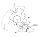
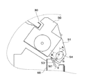
図2は、シート後処理装置のステイプラ50付近の構成を示す図、図3は、解除カム54により開放レバー53が押し下げられた状態を示す図、図4は、移動収容部51の開閉蓋52が開状態から閉状態になる方向に回動する状態を示す図である。
FIG. 2 is a diagram showing a configuration in the vicinity of the
図2乃至図4において、ステイプラ50の切断機構により切断され移動収容部51に収納された針足H(図9参照)は、綴じ処理(ステイプルジョブ)の間に、移動収容部51の最大収納量に近くなったか又は最大収納量に達した段階で、針屑ボックス60内に落下される。針足は、移動収容部51内では重力の作用により移動収容部51の下方部に収納されている。移動収容部51の底面には開閉可能な部材としての開閉蓋52が配設されている。開閉蓋52は、綴じ処理中等において針足が落下しないようにするために閉状態が維持される。
2 to 4, the needle foot H (see FIG. 9) cut by the cutting mechanism of the
開放レバー53は、開閉蓋52の開閉動作を物理的に制御するための部材であり、開放レバー53の変位に連動させて開閉蓋52を開閉動作する。解除カム54は、開放レバー53の近傍に配設されており、所定の駆動源からプーリベルト55を介して駆動力を得ることで回転するように構成されている。解除カム54は、図2の矢印b方向(反時計方向)に回転することで開放レバー53を押し下げ、図3に示す状態となる。
The opening
解除カム54により開放レバー53が押し下げられると、開閉蓋52は図3の矢印c方向に回動し、閉状態から開状態となる。これにより、ステイプラ50の切断機構により切断された針足が図3の矢印d方向に落下し、針屑ボックス60に収納される。解除カム54が更に回転することで1回転すると、図4に示す状態となる。解除カム54が1回転すると必然的に位相が元に戻り、開閉蓋52は図4の矢印e方向に回動し、開状態から閉状態となる。
When the
尚、図2乃至図4において、解除カム54における角度Aは、開閉蓋52が閉状態から開状態に変位する時のカム面の位相角度(回転角度)である。反対に、解除カム54における角度Bは、開閉蓋52が開状態から閉状態に変位する時のカム面の位相角度(回転角度)である。
2 to 4, the angle A in the
移動収容部51内の針足を重力により針屑ボックス60に落下させる場合、開閉蓋52を短時間で開放させる方が、切断された針足の落下を助長・促進でき、切断された針足が移動収容部51内に残りにくくなる。また、開閉蓋52の閉動作を時間をかけて行った方が、針足の飛散や引っ掛かり等の不具合が減少する。
When dropping the needle foot in the moving
そこで、本実施の形態では、解除カム54を同じ速度で回転する場合に、開閉蓋52を閉状態から開状態に変位させる時間と開状態から閉状態に変位させる時間とに差異を生じさせる。即ち、解除カム54としては、図2乃至図4における角度Aと角度Bに関して「A<B」の関係を有するカムを用いる。
Therefore, in the present embodiment, when the
これにより、解除カム54の回転角速度を一定にした場合、回転角の小さい角度Aの状態が、回転角の大きい角度Bの状態より短時間となる。従って、開閉蓋52の閉動作に要する時間を開動作に要する時間より長くすることができるので、針足の落下を助長させつつ、針足の飛散や引っかかりを防止することが可能となる。また、開閉蓋52の開閉動作を複数回行うことにより、上記同様に針足の落下を助長させることが可能となる。また、開閉蓋52の開閉動作を連続して行うことにより、針足を確実に落下させることが可能となる。
Thereby, when the rotational angular velocity of the
次に、ステイプラ50と針屑ボックス60の位置関係について図5に基づき説明する。
Next, the positional relationship between the
図5(a)は、ステイプラ50付近を装置上方側から見た場合でステイプラ50が綴じ位置に停止している状態を示す図、図5(b)は、ステイプラ50が針屑ボックス60の位置まで移動した状態を示す図である。
FIG. 5A is a view showing a state in which the
図5において、図5(a)は、ステイプラ50が、シート束の2ヵ所を綴じる2ヵ所綴じ処理モードにおける装置奥側の綴じ位置(第1ステイプル位置)に停止している状態を示している。ステイプラ50は、移動手段としてのステッピングモータからなるステイプラ移動モータ(不図示)により移動レール97上を駆動ベルトを介して、装置手間前側と装置奥側との間で移動可能に構成されている。尚、装置手前側とはシート後処理装置の正面に設置されているメンテナンス用ドア(不図示)に対応する側である。
In FIG. 5, FIG. 5A shows a state in which the
図5(b)は、ステイプラ50が、針屑ボックス60の位置に移動した状態を示している。移動収容部51に収納された針足を捨てる際には、ステイプラ50を針屑ボックス60(点線部)の上部に移動させ、針足を針屑ボックス60へ落下させる。尚、2ヵ所綴じ処理モードでは、ステイプラ50は第1ステイプル位置と第2ステイプル位置でシート束を綴じるステイプル動作を行う。
FIG. 5B shows a state in which the
本実施の形態では、屑箱ボックス60は、ステイプラ50によりシートを綴じるジョブの休止期間(スタンバイ)中の待機位置(ステイプラホームポジション)の近傍に配設されている。待機位置(ステイプラホームポジション)は、シート後処理装置のメンテナンス用ドアに対応する最も手前側の位置(図5(b)のステイプラ50の位置)に設定されている。即ち、ステイプラ50の待機位置と針屑ボックス60に針足を捨てる位置とを同じにしているため、ステイプラ50が装置手前側の待機位置へ移動すると開閉蓋52は開状態になるように構成されている。
In the present embodiment, the
次に、ステイプラ50の切断機構の概略構成について図6に基づき説明する。
Next, a schematic configuration of the cutting mechanism of the
図6(a)は、処理トレイ25に積載されたシート束を装置手前側から見た場合でステイプル針の先端部がシート束から飛び出た状態を示す図、図6(b)は、(a)の状態を矢印方向から見た状態を示す図である。
FIG. 6A is a diagram showing a state in which the front end of the staple staples protrudes from the sheet bundle when the sheet bundle loaded on the
図6において、ステイプラ50は、切断機構としてのカッタ部151を備えている。図中152はシート束を貫通した針であり、針152の点線部はシート束内部にあることを示している。処理トレイ25に所定枚数のシートからなるシート束が積載されると、ステイプラ50によりシート束に針が打ち込まれ、図6(a)に示すように、針152の先端部がシート束より飛び出た状態となる。
In FIG. 6, the
このとき、針152におけるライン(Z)部より上の部分は針152の針足を折り曲げる工程で余剰部分となるので、カッタ部151により余剰部分の針足を切断する。カッタ部151は、矢印(Y)方向へ移動することにより、ライン(Z)よりはみ出た針足を切断する。この場合、シート束の2ヵ所を綴じる2ヵ所綴じ処理モードでは、カッタ部151は2本の針152の針足をほぼ同時に切断する。
At this time, a portion above the line (Z) portion of the
切断された針足は、ステイプラ50に付設された移動収容部51に収納される。カッタ部151により針152の針足を切断した後、残りの針足を折り曲げる工程を実行することにより、ステイプル処理を完成させる。ステイプラ50におけるステイプル打ち込み動作から、針足切断、針足折り曲げ工程までは、上記DCブラシモータ(不図示)の駆動により行う。
The cut needle foot is stored in a moving
次に、針屑ボックス60の機構及び針屑ボックス60に収納された針足の量の検知について図7乃至図9に基づき説明する。
Next, the mechanism of the
図7は、移動収容部51及び針屑ボックス60付近の構成を示す図、図8は、針屑ボックス60がセットされていない状態を示す図、図9は、針屑ボックス60に針足が溜まった状態を示す図である。
FIG. 7 is a diagram showing a configuration near the moving
図7乃至図9において、針屑ボックス60に収納された針足を効率良く廃棄するためには、針屑ボックス60が確実にシート後処理装置内にセットされている状態を検知する必要がある。また、針屑ボックス60内に収納された針足の量を検知する必要も生じる。針屑ボックス60は、支持板61に支持されている。支持板61は、針屑ボックス60を支持したまま図7乃至図9の上下方向に移動することが可能である。また、支持板61には、検知フラッグ63、針屑ボックス検知レバー64が装備されている。更に、支持板61の側方部には、検知部62が配設されている。
7 to 9, in order to efficiently discard the needle feet stored in the
針屑ボックス60は、内部に針足が溜まってくると、その重みにより鉛直方向(図8の矢印h方向)に移動する。支持板61に装備された検知フラッグ63も、針屑ボックス60の移動に連動して移動する。検知フラッグ63は、針屑ボックス60内の針足の収納量を検知する。針屑ボックス検知レバー64は、針屑ボックス60がシート後処理装置内にセットされている状態(セット状態)と、セットされていない状態(非セット状態)との両状態を検知するレバーである。
The
次に、実際の針屑ボックス60のセット状態/非セット状態の検知方法及び針屑ボックス60に収納された針足の量の検知方法について説明する。
Next, a method for detecting the actual set state / non-set state of the
上記検知部62としては反射型センサを挙げることができる。反射型センサは、対象物が発光面に対して所定の位置に存在する場合とそれ以外の場合とにおいて異なる信号を発信することで、対象物の状態を検知することが可能である。本実施の形態では、検知部62に対して近接しているL1ラインの近傍に対象物が存在する場合と、L1ラインよりも離れているL2ラインの近傍に対象物が存在する場合とにおいて、検知部62から異なる信号が生成され出力される。
An example of the
L1ラインの近傍に対象物が存在する場合に検知部62から出力される信号を「第1の信号」とし、L2ラインの近傍に対象物が存在する場合に検知部62から出力される信号を「第2の信号」とすると、以下の(i)、(ii)、(iii)の3つの場合に分類することができる。
A signal output from the
(I)「第1の信号」については(i)、(ii)の場合がある。
(i)図8に示すように、針屑ボックス60がシート後処理装置内にセットされておらず、セット検知手段としての針屑ボックス検知レバー64の検知面65がL1ライン近傍に存在する場合。
(ii)図9に示すように、針屑ボックス60内に針足が溜まり、針屑ボックス60、支持板61及び検知フラッグ63が下降して、針足収納量検知手段としての検知フラッグ63の検知面66がL1ライン近傍に存在する場合。
(I) The “first signal” may be (i) or (ii).
(I) As shown in FIG. 8, when the
(Ii) As shown in FIG. 9, the needle foot accumulates in the
(II)「第2の信号」については(iii)の場合がある。
(iii)図7に示すように、針屑ボックス60がシート後処理装置内にセットされていると共に、針屑ボックス60内の針足の量が所定量に達しておらず、針屑ボックス検知レバー64の検知面65が変位してL2ライン近傍に存在する場合。
(II) The “second signal” may be (iii).
(Iii) As shown in FIG. 7, the
これにより、次の2つの状態を1つの検知部62を用いて検知することが可能となる。即ち、使用者がシート後処理装置内の確認を必要とする第1の信号の状態(シート後処理装置内に針屑ボックス60がセットされていない状態)と、シート後処理装置にセットされた針屑ボックス60内に針足が所定量以上収納されている状態である。そして、検知部62の検知結果に基づいて、使用者に対して警告等の必要なメッセージをシート後処理装置の操作部等に表示することが可能となる。
As a result, the following two states can be detected using one
また、針屑ボックス60に溜まった針足の廃却のために、通常、針屑ボックス60自体をシート後処理装置外部に取り出す構成が採用される。そこで、本実施の形態では、針屑ボックス60を取り出す際の操作性を向上させるために、開閉蓋52の開閉動作時の移動範囲と針屑ボックス60の取り出し方向とが互いに干渉しないように構成している。開閉蓋52と針屑ボックス60とが互いに制約を受けないように構成したものを図10に示す。
In order to dispose of the needle feet accumulated in the
図10は、移動収容部51と針屑ボックス60との間に中間固定ガイド67を配設した構成を示す図である。
FIG. 10 is a view showing a configuration in which an
図10において、ステイプラ50に付設された移動収容部51と針屑ボックス60との間に、中間固定ガイド67が配設されており、中間固定ガイド67内において開閉蓋52の開閉動作が行われる。これにより、開閉蓋52の開閉状態に関わらずシート後処理装置から針屑ボックス60を容易に取り出すことが可能となる。
In FIG. 10, an
次に、画像形成装置及びシート後処理装置からなる構成において特にシート後処理装置を制御する制御系の構成について図11に基づき説明する。 Next, a configuration of a control system for controlling the sheet post-processing apparatus in the configuration including the image forming apparatus and the sheet post-processing apparatus will be described with reference to FIG.
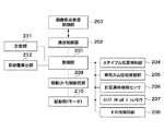
図11は、シート後処理装置を中心とした制御系の構成を示すブロック図である。 FIG. 11 is a block diagram illustrating a configuration of a control system centering on the sheet post-processing apparatus.
図11において、シート後処理装置は、制御部201、通信制御部202、ステイプル位置検知部204、解除カム位相検知部205、針足満杯検知センサ101、ステイプラホームポジションセンサ207、その他検知部208を備えている。更に、シート後処理装置は、駆動制御回路(モータ制御回路)209、駆動部(モータ)210、計数部(ステイプルカウンタ)211、収納量算出部212を備えている。203は画像形成装置側に配設された画像形成装置制御部である。
11, the sheet post-processing apparatus includes a
ステイプル位置検知部204は、シート束に対するステイプル位置を検知する。解除カム位相検知部205は、解除カム54の位相角度を検知する。ステイプラホームポジションセンサ207は、ステイプラ50がステイプラホームポジション(待機位置)にあるか否かを検知する。その他検知部208は、搬送路のシートの通過を検知するセンサ等である。針足満杯検知センサ101は、移動収容部51が針足で満杯か否かを検知するものであり、例えば反射型センサとして構成されている。針足満杯検知センサ101については第3の実施の形態で後述する。
The staple
ステイプル位置検知部204、解除カム位相検知部205、針足満杯検知センサ101、ステイプラホームポジションセンサ207及びその他の検知部208からの検知信号は、制御部201に供給される。制御部201は、CPU、プログラムや後述する重み付けテープルを格納するROM、一時的にデータ記憶等に使用するRAM(以上不図示)等から構成されており、上記プログラムに基づいて後述の各フローチャートに示す処理を実行する。通信制御部202は、制御部201と画像形成装置制御部203との間の通信処理を行う。
Detection signals from the staple
計数部(ステイプルカウンタ)211は、ステイプルジョブ中におけるシート束を綴じるステイプル回数を計数する。収納量算出部212は、計数部211の計数結果と上記重み付けテーブル等に基づき、移動収容部51の針足収納量を算出する。制御部201は、上記検知信号と針足収納量算出結果に基づいて、駆動制御回路209に制御信号を供給する。駆動制御回路209は、駆動制御信号を生成して駆動部210に出力することで駆動部210を駆動し、ステイプラ打ち込み動作及びステイプル切断動作からなるステイプル動作を行うステイプラ50や解除カム54等の各負荷を駆動する。
A counting unit (staple counter) 211 counts the number of staples for binding the sheet bundle in the staple job. The storage
次に、シート後処理装置のステイプル処理について図12のフローチャートに基づき説明する。 Next, stapling processing of the sheet post-processing apparatus will be described based on the flowchart of FIG.
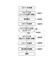
図12は、ステイプル処理を示すフローチャートである。 FIG. 12 is a flowchart showing the stapling process.
図12において、シート後処理装置の制御部201は、ステイプル処理モードに入ると、ステイプラ50をステイプル位置へ所定量移動させる(ステップS401)。次に、制御部201は、上記手前整合部材及び奥整合部材からなる整合部32により処理トレイ25上のシート束を整合し(ステップS402)、ステイプラ50によりステイプル位置でステイプル動作を行う(ステップS403)。次に、制御部201は、ステイプル処理モードがシート束の2ヵ所を綴じる2ヵ所綴じ処理モードであるかどうかを判断する(ステップS404)。
In FIG. 12, when entering the staple processing mode, the
2ヵ所綴じ処理モードでないと判断した場合は、制御部201は、整合部32によるシート束の整合を解除し(ステップS407)、本処理を終了する。他方、2ヵ所綴じ処理モードであると判断した場合は、制御部201は、ステイプラ50を上記ステイプル位置(第1ステイプル位置)から第2ステイプル位置まで所定量移動させ(ステップS405)、2ヵ所目のステイプル動作を行う(ステップS406)。次に、制御部201は、整合部32によるシート束の整合を解除し(ステップS407)、本処理を終了する。ここで、ステイプラ50は最終のシート束のステイプル処理を終了すると待機位置へ移動される。
If it is determined that the mode is not the two-point binding processing mode, the
次に、本実施の形態の特徴的な部分について説明する。 Next, characteristic parts of the present embodiment will be described.
本実施の形態では、移動収容部51の針足の最大収納量は、例えば「200針足」分に設定されている。従って、2ヵ所綴じ処理モードの場合でシート100束分、1ヵ所綴じ処理モードの場合でシート200束分の針足を移動収容部51に収納することができる。しかしながら、シート後処理装置では、移動収容部51の針足の最大収納量を超えるシート束数のステイプル処理が設定されると、ジョブの途中で移動収容部51から針足が溢れてしまうことが考えられる。
In the present embodiment, the maximum accommodation amount of the needle foot of the moving
上記のような移動収容部51から針足が溢れることを防止する処理及び針足を捨てる処理について図13及び図14に基づき説明する。
A process for preventing the needle foot from overflowing from the moving
図13は、ステイプル針足処理を示すフローチャートである。 FIG. 13 is a flowchart showing staple staple leg processing.
図13において、ジョブとしてシート束を綴じるステイプルジョブを想定する。まず、シート後処理装置の制御部201は、処理トレイ25上に積載されたシート束にステイプラ50によりステイプルを行ったかどうかを判断する(ステップS501)。シート束にステイプルを行ったと判断した場合は、制御部201は、ステイプラ50によるステイプル回数(綴じ回数)を計数するステイプルカウンタをインクリメントする(ステップS502)。次に、制御部201は、当該ジョブが終了したかどうかを判断する(ステップS503)。当該ジョブが終了したと判断した場合は、本処理を終了する。
In FIG. 13, a staple job for binding a sheet bundle is assumed as a job. First, the
他方、ステイプルすべき後続のジョブがあると判断した場合は、制御部201は、ステイプルカウンタの計数値が200回に達したかどうかを判定する(ステップS504)。ステイプルカウンタの計数値が200回未満であると判断した場合は、ステップS501に戻る。ステイプルカウンタの計数値が200回に達したと判断した場合は、制御部201は、移動収容部51に収納された切断された針足を捨てる処理(図14)を行う(ステップS505)。針足を捨てる処理が終了すると、ステップS501に戻る。
On the other hand, when determining that there is a subsequent job to be stapled, the
図14は、切断された針足を捨てる処理を示すフローチャートである。 FIG. 14 is a flowchart showing a process of discarding the cut needle foot.
図14において、まず、シート後処理装置の制御部201は、ステイプラ50をステイプラホームポジション(待機位置)に移動する(ステップS511)。ステイプラホームポジションは、上述したようにシート後処理装置のメンテナンス用ドアに対応する最も手前側の位置に設定されている。次に、制御部201は、ステイプラ50がステイプラホームポジションに到達すると、解除カム54を回転させることで開閉蓋52を開放する(ステップS512)。
In FIG. 14, first, the
次に、制御部201は、移動収容部51から針足が針屑ボックス60へ落下するまで所定時間(例えば2秒)の間待機する(ステップS513)。次に、制御部201は、解除カム54を回転させることで開閉蓋52を閉める(ステップS514)。次に、制御部201は、ステイプラ50をステイプル位置(綴じ位置)へ再度移動し(ステップS515)、後続のステイプルジョブに備える。次に、制御部201は、ステイプルカウンタを0クリアし(ステップS516)、本処理を終了する。
Next, the
上記のように、移動収容部51の針足の収納量を超える前にステイプル針足処理を実行することにより、移動収容部51から針足が溢れることを防止することができる。また、ジョブが終了すると、ステイプラ50をステイプラホームポジションに戻し、移動収容部51に溜まった針足を針屑ボックス60に捨て、次のジョブに備える。この処理により、次のジョブ開始前には移動収容部51を空にすることができる。また、このときにステイプルカウンタを0クリアする。
As described above, it is possible to prevent the needle feet from overflowing from the moving
以上説明したように、本実施の形態によれば、移動収容部51内の針足量の算出結果に基づいて、移動収容部51内の針足を針屑ボックス60へ捨てるため、移動収容部51内の針足を適切なタイミングで捨てる処理が可能となる。これにより、移動収容部51から針足が溢れシート後処理装置内に散乱することを防止でき、使い勝手を向上させることが可能となる。
As described above, according to the present embodiment, based on the calculation result of the needle foot amount in the moving
[第2の実施の形態]
本発明の第2の実施の形態は、上述した第1の実施の形態に対して、下記の点において相違する。本実施の形態のその他の要素は、上述した第1の実施の形態(図1乃至図11)の対応するものと同一なので、説明を省略する。
[Second Embodiment]
The second embodiment of the present invention is different from the first embodiment described above in the following points. The other elements of the present embodiment are the same as the corresponding ones of the first embodiment (FIGS. 1 to 11) described above, and a description thereof will be omitted.
シート後処理装置のステイプラ50の切断機構により切断される針足の長さは、ステイプルを行うシート束の厚みに応じて異なる。つまり、ステイプルを行うシート束の厚みが厚いほど切断される針足の量は少なくなり、逆に、ステイプルを行うシート束の厚みが薄いほど切断される針足の量は多くなる。
The length of the needle foot cut by the cutting mechanism of the
そこで、本実施の形態では、ステイプルを行うシート束の厚み(シート束のシート枚数)に応じて重み付け係数を設定し、移動収容部51に収納できる針足数をできる限り多くし、移動収容部51に収納された針足を針屑ボックス60へ捨てる回数を減らす制御を行う。
Therefore, in the present embodiment, a weighting coefficient is set according to the thickness of the sheet bundle to be stapled (the number of sheets in the sheet bundle), and the number of needle feet that can be stored in the moving
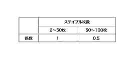
図15は、本実施の形態に係るシート処理装置としてのシート後処理装置におけるステイプルを行うシート束のシート枚数に対する重み付け係数の設定例を示す図である。 FIG. 15 is a diagram illustrating an example of setting a weighting coefficient for the number of sheets of a sheet bundle to be stapled in the sheet post-processing apparatus as the sheet processing apparatus according to the present embodiment.
図15において、ステイプルを行うシート束のシート枚数が例えば2〜50枚までは、重み付け係数=1が設定され、ステイプルを行うシート束のシート枚数が例えば51〜100枚までは、重み付け係数=0.5が設定される。即ち、シート枚数が51〜100枚のシート束の場合は、それよりもシート枚数が少ない(薄い)シート束と比較してステイプル針から切断される針足の長さが短いので、0.5本分として計算する。ステイプルを行うシート束のシート枚数(ステイプル枚数)に対する重み付け係数の設定を示す重み付けテーブルは、シート後処理装置の制御部201のROMに格納されている。
In FIG. 15, the weighting factor = 1 is set when the number of sheets of the sheet bundle to be stapled is 2 to 50, for example, and the weighting coefficient is 0 when the number of sheets of the sheet bundle to be stapled is 51 to 100, for example. .5 is set. That is, in the case of a sheet bundle of 51 to 100 sheets, the length of the needle foot cut from the staple is shorter than that of a sheet bundle having a smaller (thin) number of sheets than that of the sheet bundle. Calculate as the actual amount. A weighting table indicating the setting of the weighting coefficient for the number of sheets of the sheet bundle to be stapled (staple number) is stored in the ROM of the
次に、本実施の形態のステイプル針足処理について図16のフローチャートに基づき説明する。 Next, the staple needle leg processing of the present embodiment will be described based on the flowchart of FIG.
図16は、ステイプル針足処理を示すフローチャートである。 FIG. 16 is a flowchart showing staple staple leg processing.
図16において、まず、シート後処理装置の制御部201は、ステイプラ50によりステイプルを行うシート束のシート枚数(シート束枚数)がどの範囲(1〜50枚、51〜100枚)にあるかを判断する(ステップS531)。シート束枚数が1〜50枚と判断した場合は、制御部201は、重み付け係数=1を設定する(ステップS532)。他方、シート束枚数が51〜100枚と判断した場合は、制御部201は、重み付け係数=0.5を設定する(ステップS533)。
In FIG. 16, first, the
次に、制御部201は、ステイプラ50によりシート束にステイプルを行ったかどうかを判定する(ステップS534)。シート束にステイプルを行ったと判断した場合は、制御部201は、ステイプルカウンタをインクリメントする(ステップS535)。次に、制御部201は、上記設定された重み付け係数に基づいて、式「X=X+ステイプルカウンタの計数値×重み付け係数」により、移動収容部51に収納された針足の数を計数する容量カウンタの値Xを計算する(ステップS536)。この場合、移動収容部51の針足の最大収納量は200針足分に設定されているものとする。
Next, the
次に、制御部201は、ジョブが終了したかどうか(ステイプルを行ったシート束が最終のシート束かどうか)を判断する(ステップS537)。ジョブが終了したと判断した場合は、本処理を終了する。他方、ジョブが終了していないと判断した場合は、制御部201は、容量カウンタの値Xが200以上になったかどうかを判断する(ステップS538)。
Next, the
容量カウンタの値Xが200未満であると判断した場合は、ステップS531に戻る。他方、容量カウンタの値Xが200以上になったと判断した場合は、制御部201は、移動収容部51に収納された針足を針屑ボックス60へ捨てる処理を行う(ステップS539)。ステップS539の切断された針足を捨てる処理は、上記図14に示した処理(ステップS511〜ステップS516)と同様であり、説明を省略する。ステップS539の処理が終了すると、ステップS531に戻る。
If it is determined that the value X of the capacity counter is less than 200, the process returns to step S531. On the other hand, when determining that the value X of the capacity counter has become 200 or more, the
以上説明したように、本実施の形態によれば、ステイプルを行うシート束の枚数に応じて重み付け係数を変更することにより、ステイプラ50の切断機構により切断された針足の長さが短い場合には、移動収容部51に針足を多く収納することが可能となる。これにより、移動収容部51から針屑ボックス60へ針足を捨てるまでの各シート束に対するステイプル回数を増やすことが可能となり、その結果、ジョブ中に針屑ボックス60へ針足を捨てる回数を減らすことが可能となる。
As described above, according to the present embodiment, when the length of the needle foot cut by the cutting mechanism of the
[第3の実施の形態]
本発明の第3の実施の形態は、上述した第1の実施の形態に対して、下記の点において相違する。本実施の形態のその他の要素は、上述した第1の実施の形態(図1乃至図11)の対応するものと同一なので、説明を省略する。
[Third Embodiment]
The third embodiment of the present invention is different from the above-described first embodiment in the following points. The other elements of the present embodiment are the same as the corresponding ones of the first embodiment (FIGS. 1 to 11) described above, and a description thereof will be omitted.
本実施の形態では、移動収容部51に収納されている針足量を検知する方法として、図17に示すように針足満杯検知センサ101により検知する方法をとる。
In the present embodiment, as a method of detecting the amount of the needle foot stored in the moving
図17は、本実施の形態に係るシート処理装置としてのシート後処理装置における針足満杯検知センサ101により針足を検知する例を示す図である。
FIG. 17 is a diagram illustrating an example in which the needle foot is detected by the needle foot
図17において、移動収容部51の近傍で且つ移動収容部51の上端部の開口部を臨む位置には、針足満杯検知センサ101が配設されている。針足満杯検知センサ101は、ステイプラ50の切断機構により切断され移動収容部51に収納された針足の頂上部(点線(a)部)を検知する。尚、針足満杯検知センサ101としては、上述したように反射型センサを用いているが、他の種類のセンサを用いてもよい。
In FIG. 17, a needle foot
次に、本実施の形態のステイプル針足処理について図18のフローチャートに基づき説明する。 Next, the staple needle leg processing of the present embodiment will be described based on the flowchart of FIG.
図18は、ステイプル針足処理を示すフローチャートである。 FIG. 18 is a flowchart showing staple staple leg processing.
図18において、まず、シート後処理装置の制御部201は、処理トレイ25上に積載されたシート束にステイプラ50によりステイプルを行ったかどうかを判断する(ステップS561)。シート束にステイプルを行ったと判断した場合は、制御部201は、ジョブが終了したかどうかを判断する(ステップS)。ジョブが終了したと判断した場は、本処理を終了する。他方、ステイプルすべき後続のシート束があると判断した場合は、制御部201は、移動収容部51が収納した針足で満杯になったかどうかを判定する(ステップS563)。これは、針足満杯検知センサ101により移動収容部51内の針足の頂上部(図17の点線(a)部)を検知することにより判定する。
In FIG. 18, first, the
移動収容部51が満杯で無いと判断した場合は、ステップS561に戻る。他方、移動収容部51が満杯であると判断した場合は、制御部201は、移動収容部51に収納された針足を針屑ボックス60へ捨てる処理を行う(ステップS564)。ステップS564の切断された針足を捨てる処理は、上記図14に示した処理(ステップS511〜ステップS516)と同様であり、説明を省略する。針足を捨てる処理を終了すると、ステップS561に戻る。
If it is determined that the
以上説明したように、本実施の形態によれば、針足満杯検知センサ101により移動収容部51内の針足の頂上部を検知した場合に、移動収容部51内の針足を針屑ボックス60へ捨てる処理を行う。これにより、移動収容部51から針足が溢れシート後処理装置内に散乱することを防止でき、使い勝手を向上させることが可能となる。
As described above, according to the present embodiment, when the needle foot
[第4の実施の形態]
本発明の第4の実施の形態は、上述した第1の実施の形態に対して、下記の点において相違する。本実施の形態のその他の要素は、上述した第1の実施の形態(図1乃至図11)の対応するものと同一なので、説明を省略する。
[Fourth Embodiment]
The fourth embodiment of the present invention differs from the above-described first embodiment in the following points. The other elements of the present embodiment are the same as the corresponding ones of the first embodiment (FIGS. 1 to 11) described above, and a description thereof will be omitted.
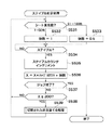
本実施の形態は、第3の実施の形態の変形例であり、ステイプラ50によるステイプル回数(綴じ回数)を計数するステイプルカウンタの計数値に基づき移動収容部51における針足量が満杯になったかどうかを判定し、移動収容部51内の針足を針屑ボックス60に捨てる処理を行う。
The present embodiment is a modification of the third embodiment, and is the amount of staples in the moving
次に、本実施の形態のステイプル針足処理について図19のフローチャートに基づき説明する。 Next, the staple needle leg processing of the present embodiment will be described based on the flowchart of FIG.
図19は、ステイプル針足処理を示すフローチャートである。 FIG. 19 is a flowchart showing staple staple leg processing.
図19において、まず、シート後処理装置の制御部201は、処理トレイ25上に積載されたシート束にステイプラ50によりステイプルを行ったかどうかを判断する(ステップS571)。シート束にステイプルを行ったと判断した場合は、制御部201は、ステイプルカウンタをインクリメントする(ステップS572)。次に、制御部201は、ジョブが終了したかどうかを判断する(ステップS573)。ジョブが終了したと判断した場合は、本処理を終了する。
In FIG. 19, first, the
他方、ステイプルすべき後続のジョブがあると判断した場合は、制御部201は、ステイプルカウンタの計数値が200回に達したかどうかを判定する(ステップS574)。ステイプルカウンタの計数値が200未満であると判断した場合は、ステップS576に進み、ステイプルカウンタの計数値が200回に達したと判断した場合は、ステップS575に進む。
On the other hand, when determining that there is a subsequent job to be stapled, the
ステイプルカウンタの計数値が200未満の場合、制御部201は、移動収容部51が収納した針足で満杯になったかどうかを判定する(ステップS576)。これは、針足満杯検知センサ101により移動収容部51内の針足の頂上部(図17の点線(a)部)を検知することにより判定する。
When the count value of the staple counter is less than 200, the
移動収容部51が満杯で無いと判断した場合は、ステップS571に戻る。他方、移動収容部51が満杯であると判断した場合は、制御部201は、移動収容部51内の針足を針屑ボックス60へ捨てる処理を行う(ステップS575)。ステップS575の切断された針足を捨てる処理は、上記図14に示した処理(ステップS511〜ステップS516)と同様であり、説明を省略する。針足を捨てる処理が終了するとステップS571に戻る。
If it is determined that the
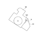
図20は、針足満杯検知センサ101により針足を検知する例を示す図である。
FIG. 20 is a diagram illustrating an example in which the needle foot is detected by the needle foot
図20において、点線(b)で示すように、移動収容部51内において針足が堆積した形状が一部だけ高くなってしまった場合には、ステイプルカウンタの計数値が規定値(200)に達する前に移動収容部51の頂上部に針足が到達してしまう可能性がある。その場合でも、針足満杯検知センサ101により移動収容部51内の針足の頂上部を検知することにより針足を捨てる処理を行うことができるので、移動収容部51から針足が溢れることを防止できる。
In FIG. 20, when the shape in which the needle foot is accumulated in the moving
以上説明したように、本実施の形態によれば、ステイプルカウンタの計数値が規定値に達した場合、または針足満杯検知センサ101により移動収容部51内の針足の頂上部を検知した場合に、移動収容部51内の針足を針屑ボックス60へ捨てる処理を行う。このため、針足満杯検知センサ101が故障した場合においても、移動収容部51内の針足を適切なタイミングで捨てる処理が可能となる。これにより、移動収容部51から針足が溢れシート後処理装置内に散乱することを防止でき、使い勝手を向上させることが可能となる。
As described above, according to the present embodiment, when the count value of the staple counter reaches the specified value, or when the top of the needle foot in the moving
[第5の実施の形態]
本発明の第5の実施の形態は、上述した第1の実施の形態に対して、下記の点において相違する。本実施の形態のその他の要素は、上述した第1の実施の形態(図1乃至図11)の対応するものと同一なので、説明を省略する。
[Fifth Embodiment]
The fifth embodiment of the present invention differs from the above-described first embodiment in the following points. The other elements of the present embodiment are the same as the corresponding ones of the first embodiment (FIGS. 1 to 11) described above, and a description thereof will be omitted.
本実施の形態は、第4の実施の形態の変形例であり、移動収容部51に収納された針足の数を計数する容量カウンタの計数値に基づき、移動収容部51内の針足を針屑ボックス60に捨てる処理を行う。
The present embodiment is a modification of the fourth embodiment, and the needle feet in the moving
次に、本実施の形態のステイプル針足処理について図21のフローチャートに基づき説明する。 Next, the staple needle leg processing of the present embodiment will be described based on the flowchart of FIG.
図21は、ステイプル針足処理を示すフローチャートである。 FIG. 21 is a flowchart showing staple staple leg processing.
図21において、ステップS581〜ステップS587の処理は、上記図16のステップS531〜ステップS537の処理と同様であり、説明を省略する。シート後処理装置の制御部201は、容量カウンタの値Xが200以上になったかどうかを判断する(ステップS588)。容量カウンタの値Xが200未満であると判断した場合は、ステップS590に進み、容量カウンタの値Xが200回以上になったと判断した場合は、ステップS589に進む。
In FIG. 21, the processes in steps S581 to S587 are the same as the processes in steps S531 to S537 in FIG. The
容量カウンタの値Xが200未満の場合、制御部201は、移動収容部51が収納した針足で満杯になったかどうかを判定する(ステップS590)。これは、針足満杯検知センサ101により移動収容部51内の針足の頂上部(図17の点線(a)部)を検知することにより判定する。
When the value X of the capacity counter is less than 200, the
移動収容部51が満杯で無いと判断した場合は、ステップS581に戻る。他方、移動収容部51が満杯であると判断した場合は、制御部201は、移動収容部51内の針足を針屑ボックス60へ捨てる処理を行う(ステップS589)。ステップS589の切断された針足を捨てる処理は、上記図14に示した処理(ステップS511〜ステップS516)と同様であり、説明を省略する。針足を捨てる処理が終了すると、ステップS581に戻る。
If it is determined that the
以上説明したように、本実施の形態によれば、容量カウンタの値が規定値以上となった場合、または針足満杯検知センサ101により移動収容部51内の針足の頂上部を検知した場合に、移動収容部51内の針足を針屑ボックス60へ捨てる処理を行う。このため、移動収容部51内の針足量を更に精度良く測定できると共に、移動収容部51内の針足を適切なタイミングで捨てる処理が可能となる。これにより、移動収容部51から針足が溢れシート後処理装置内に散乱することを防止でき、使い勝手を向上させることが可能となる。
As described above, according to the present embodiment, when the value of the capacity counter is equal to or greater than the specified value, or when the top of the needle foot in the
[他の実施の形態]
上記第1乃至第5の実施の形態では、シート後処理装置の構成及び動作を図1乃至図21を用いて具体的に説明したが、本発明は、上記各実施の形態に限定されるものではなく、本発明の技術的思想に基づく各種の変形が可能である。
[Other embodiments]
In the first to fifth embodiments, the configuration and operation of the sheet post-processing apparatus have been specifically described with reference to FIGS. 1 to 21. However, the present invention is limited to the above-described embodiments. Instead, various modifications based on the technical idea of the present invention are possible.
上記第1乃至第5の実施の形態では、制御部201が移動収容部51に収納された針足量をステイプルカウンタや針足満杯検知センサを用いて判定する場合を例に挙げたが、本発明は、これに限定されるものではない。画像形成装置から搬送された画像形成が完了したシートを整合したシート束を綴じるステイプル処理モード時におけるシート束の設定部数に基づいて、制御部201が移動収容部51に収納されると予測される針足量を判定するように構成してもよい。
In the first to fifth embodiments, the case where the
上記第1乃至第5の実施の形態では、制御部201が移動収容部51に収納された針足量をステイプルカウンタや針足満杯検知センサを用いて判定する場合を例に挙げたが、本発明は、これに限定されるものではない。制御部201が移動収容部51に収納された針足量を例えば重量検知センサ等を用いて判定するように構成してもよい。
In the first to fifth embodiments, the case where the
また、本発明の目的は、実施形態の機能を実現するソフトウェアのプログラムコードを記録した記憶媒体を、システム或いは装置に供給し、そのシステム或いは装置のコンピュータ(またはCPUやMPU等)が記憶媒体に格納されたプログラムコードを読み出して実行することによりも達成される。 In addition, an object of the present invention is to supply a storage medium storing software program codes for realizing the functions of the embodiments to a system or apparatus, and a computer (or CPU, MPU, etc.) of the system or apparatus as a storage medium This can also be achieved by reading and executing the stored program code.
この場合、記憶媒体から読み出されたプログラムコード自体が前述した実施の形態の機能を実現することになり、そのプログラムコード及び該プログラムコードを記憶した記憶媒体は本発明を構成することになる。 In this case, the program code itself read from the storage medium realizes the functions of the above-described embodiments, and the program code and the storage medium storing the program code constitute the present invention.
また、プログラムコードを供給するための記憶媒体としては、例えば、フロッピー(登録商標)ディスク、ハードディスク、光磁気ディスク、CD−ROM、CD−R、CD−RW、DVD−ROM、DVD−RAM、DVD−RW、DVD+RW、磁気テープ、不揮発性のメモリカード、ROM等を用いることができる。または、プログラムコードをネットワークを介してダウンロードしてもよい。 Examples of the storage medium for supplying the program code include a floppy (registered trademark) disk, a hard disk, a magneto-optical disk, a CD-ROM, a CD-R, a CD-RW, a DVD-ROM, a DVD-RAM, and a DVD. -RW, DVD + RW, magnetic tape, nonvolatile memory card, ROM, etc. can be used. Alternatively, the program code may be downloaded via a network.
また、コンピュータが読み出したプログラムコードを実行することにより、上記実施の形態の機能が実現されるだけでなく、そのプログラムコードの指示に基づき、コンピュータ上で稼動しているOS(オペレーティングシステム)等が実際の処理の一部または全部を行い、その処理により前述した実施形態の機能が実現される場合も含まれる。 Further, by executing the program code read by the computer, not only the functions of the above-described embodiments are realized, but also an OS (operating system) running on the computer based on the instruction of the program code. This includes a case where part or all of the actual processing is performed and the functions of the above-described embodiments are realized by the processing.
更に、記憶媒体から読み出されたプログラムコードが、コンピュータに挿入された機能拡張ボードやコンピュータに接続された機能拡張ユニットに備わるメモリに書き込まれた後、そのプログラムコードの指示に基づき、その機能拡張ボードや機能拡張ユニットに備わるCPU等が実際の処理の一部または全部を行い、その処理により前述した実施形態の機能が実現される場合も含まれる。 Further, after the program code read from the storage medium is written in a memory provided in a function expansion board inserted into the computer or a function expansion unit connected to the computer, the function expansion is performed based on the instruction of the program code. This includes the case where the CPU or the like provided in the board or the function expansion unit performs part or all of the actual processing, and the functions of the above-described embodiments are realized by the processing.
1 画像形成装置
10 シート後処理装置(シート処理装置)
50 ステイプラ(シート処理手段)
51 移動収容部(第1の収納部)
60 針屑ボックス(第2の収納部)
101 針足満杯検知センサ(センサ)
151 カッタ部(シート処理手段)
201 制御部(制御手段、記憶手段)
H 針足(綴じ具余剰物)
DESCRIPTION OF
50 Stapler (sheet processing means)
51 Moving storage unit (first storage unit)
60 Needle waste box (second storage part)
101 Needle foot full detection sensor ( sensor )
151 Cutter unit (sheet processing means)
201 control unit (control means, storage means)
H Needle foot (binding tool surplus)
Claims (3)
前記シート処理手段と共に移動し、前記シート処理手段により切断された綴じ具余剰物を収納する第1の収納部と、
前記第1の収納部に収納された綴じ具余剰物を収納可能な第2の収納部と、
前記シート処理手段による綴じ回数を計数する計数手段と、
前記第1の収納部に収納された綴じ具余剰物が所定の量に達したか否かを検知するセンサと、
前記計数手段の計数値が所定値となったことに応じて、前記第1の収納部内の綴じ具余剰物を前記第2の収納部に移す制御を行う制御手段と、
を備え、前記計数手段の計数値が前記所定値未満であっても、前記センサにより前記第1の収納部に収納された綴じ具余剰物が所定の量に達したことが検知されると、前記制御手段は前記第1の収納部内の綴じ具余剰物を前記第2の収納部に移す制御を行うことを特徴とするシート処理装置。 Sheet processing means for moving to a binding position of the sheet bundle, binding the sheet bundle with a binding tool, and cutting an excess portion of the binding tool;
A first storage unit that moves together with the sheet processing unit and stores the binding tool surplus cut by the sheet processing unit;
A second storage section capable of storing the binding tool surplus stored in the first storage section;
Counting means for counting the number of times of binding by the sheet processing means;
A sensor for detecting whether or not the binding tool surplus stored in the first storage unit has reached a predetermined amount;
Control means for performing control to move the binding tool surplus in the first storage part to the second storage part in response to the count value of the counting means becoming a predetermined value ;
Even if the count value of the counting means is less than the predetermined value, the sensor detects that the binding tool surplus stored in the first storage unit has reached a predetermined amount, The sheet processing apparatus according to claim 1, wherein the control unit performs control to transfer the binding tool surplus in the first storage unit to the second storage unit .
前記シート束のシート枚数を検知する枚数検知手段とを備え、
前記計数手段は、前記枚数検知手段により検知されたシート枚数に対応した重み付け係数に基づいて前記計数手段の計数値を重み付けして計数することを特徴とする請求項1記載のシート処理装置。 Storage means for storing the set weighting factors depending on the number of sheets of the sheet bundle stapled by the pre-Symbol sheet processing means,
A sheet number detecting means for detecting the number of sheets of the sheet bundle ,
The counting means, the sheet processing apparatus according to claim 1, wherein the counting by weighting the count value of said counting means on the basis of the weighting coefficient corresponding to the number of sheets detected by the sheet number detecting means.
Priority Applications (2)
| Application Number | Priority Date | Filing Date | Title |
|---|---|---|---|
| JP2005250118A JP4423249B2 (en) | 2005-08-30 | 2005-08-30 | Sheet processing device |
| US11/466,024 US7472899B2 (en) | 2005-08-30 | 2006-08-21 | Sheet processing apparatus, image forming apparatus, control method, and program |
Applications Claiming Priority (1)
| Application Number | Priority Date | Filing Date | Title |
|---|---|---|---|
| JP2005250118A JP4423249B2 (en) | 2005-08-30 | 2005-08-30 | Sheet processing device |
Publications (3)
| Publication Number | Publication Date |
|---|---|
| JP2007062913A JP2007062913A (en) | 2007-03-15 |
| JP2007062913A5 JP2007062913A5 (en) | 2008-02-21 |
| JP4423249B2 true JP4423249B2 (en) | 2010-03-03 |
Family
ID=37802984
Family Applications (1)
| Application Number | Title | Priority Date | Filing Date |
|---|---|---|---|
| JP2005250118A Expired - Fee Related JP4423249B2 (en) | 2005-08-30 | 2005-08-30 | Sheet processing device |
Country Status (2)
| Country | Link |
|---|---|
| US (1) | US7472899B2 (en) |
| JP (1) | JP4423249B2 (en) |
Families Citing this family (9)
| Publication number | Priority date | Publication date | Assignee | Title |
|---|---|---|---|---|
| JP4641504B2 (en) * | 2006-02-09 | 2011-03-02 | キヤノン株式会社 | Sheet processing apparatus and image forming apparatus |
| JP4872808B2 (en) * | 2007-05-30 | 2012-02-08 | コニカミノルタビジネステクノロジーズ株式会社 | Post-processing apparatus and image forming system |
| JP5444999B2 (en) * | 2009-09-29 | 2014-03-19 | 株式会社リコー | Image processing apparatus and image forming apparatus |
| JP5891011B2 (en) * | 2011-11-08 | 2016-03-22 | キヤノンファインテック株式会社 | Sheet processing apparatus and image forming apparatus |
| JP5747881B2 (en) * | 2012-08-31 | 2015-07-15 | コニカミノルタ株式会社 | Paper processing apparatus and image forming system |
| JP6657598B2 (en) * | 2015-05-22 | 2020-03-04 | 株式会社リコー | Sheet processing device, image forming system |
| US10654190B2 (en) * | 2015-12-22 | 2020-05-19 | Max Co., Ltd. | Stapler, post-processing apparatus and image forming system |
| JP6870280B2 (en) * | 2015-12-22 | 2021-05-12 | マックス株式会社 | Stapler, post-processing device and image forming system |
| JP6798512B2 (en) * | 2018-01-23 | 2020-12-09 | 京セラドキュメントソリューションズ株式会社 | Sheet processing equipment and image forming equipment |
Family Cites Families (4)
| Publication number | Priority date | Publication date | Assignee | Title |
|---|---|---|---|---|
| JP3541273B2 (en) | 1999-09-30 | 2004-07-07 | マックス株式会社 | Backflow prevention mechanism for staple cutting leg in electric stapler |
| US6474633B1 (en) * | 1999-10-04 | 2002-11-05 | Canon Kabushiki Kaisha | Stapler with interchangeable cartridges |
| JP4350289B2 (en) * | 1999-10-04 | 2009-10-21 | キヤノン株式会社 | Sheet processing apparatus and image forming apparatus |
| US7396008B2 (en) * | 2004-07-22 | 2008-07-08 | Fuji Xerox Co., Ltd. | Stapling device |
-
2005
- 2005-08-30 JP JP2005250118A patent/JP4423249B2/en not_active Expired - Fee Related
-
2006
- 2006-08-21 US US11/466,024 patent/US7472899B2/en not_active Expired - Fee Related
Also Published As
| Publication number | Publication date |
|---|---|
| US7472899B2 (en) | 2009-01-06 |
| JP2007062913A (en) | 2007-03-15 |
| US20070045923A1 (en) | 2007-03-01 |
Similar Documents
| Publication | Publication Date | Title |
|---|---|---|
| JP4423249B2 (en) | Sheet processing device | |
| JP5031014B2 (en) | Paper post-processing apparatus, paper post-processing method, and image forming apparatus | |
| US8231321B2 (en) | Paper-processing and punching apparatus | |
| JP5298902B2 (en) | Sheet post-processing apparatus and image forming system | |
| JP4641504B2 (en) | Sheet processing apparatus and image forming apparatus | |
| JP5120222B2 (en) | Paper post-processing apparatus and image forming system | |
| JP2006168185A (en) | Staple cartridge in stapler and treatment apparatus of cut refuse of staple legs | |
| JP4872808B2 (en) | Post-processing apparatus and image forming system | |
| JP4487670B2 (en) | Staple processing device | |
| JP2007015824A (en) | Sheet treatment device and image forming device | |
| JP2006347667A (en) | Sheet post-processing device and image forming device | |
| JP5314965B2 (en) | Paper discharge processing apparatus, image forming apparatus | |
| JP2007126233A (en) | Sheet processing device and image forming device | |
| JP4239919B2 (en) | Staple processing device | |
| JP2007099463A (en) | Sheet handling device, image forming device, and tray device | |
| JP4444400B2 (en) | Sheet processing apparatus and image forming apparatus having the same | |
| JP2015016946A (en) | Sheet processing device and image formation device | |
| JP4455852B2 (en) | Paper post-processing apparatus and image forming apparatus | |
| JP2010247957A (en) | Sheet postprocessing device and image forming system | |
| JP2006206259A (en) | Sheet handling device and image forming device | |
| JP2006035452A (en) | Staple processing apparatus | |
| JP2003026366A (en) | Sheet stacking device and image forming device | |
| JP2008120533A (en) | Sheet processing device and image forming device | |
| JP5891011B2 (en) | Sheet processing apparatus and image forming apparatus | |
| JP3886134B2 (en) | Sheet processing device |
Legal Events
| Date | Code | Title | Description |
|---|---|---|---|
| RD05 | Notification of revocation of power of attorney |
Free format text: JAPANESE INTERMEDIATE CODE: A7425 Effective date: 20070626 |
|
| A521 | Written amendment |
Free format text: JAPANESE INTERMEDIATE CODE: A523 Effective date: 20071228 |
|
| A621 | Written request for application examination |
Free format text: JAPANESE INTERMEDIATE CODE: A621 Effective date: 20071228 |
|
| A977 | Report on retrieval |
Free format text: JAPANESE INTERMEDIATE CODE: A971007 Effective date: 20090903 |
|
| A131 | Notification of reasons for refusal |
Free format text: JAPANESE INTERMEDIATE CODE: A131 Effective date: 20090908 |
|
| A521 | Written amendment |
Free format text: JAPANESE INTERMEDIATE CODE: A523 Effective date: 20091105 |
|
| TRDD | Decision of grant or rejection written | ||
| A01 | Written decision to grant a patent or to grant a registration (utility model) |
Free format text: JAPANESE INTERMEDIATE CODE: A01 Effective date: 20091201 |
|
| A01 | Written decision to grant a patent or to grant a registration (utility model) |
Free format text: JAPANESE INTERMEDIATE CODE: A01 |
|
| A61 | First payment of annual fees (during grant procedure) |
Free format text: JAPANESE INTERMEDIATE CODE: A61 Effective date: 20091207 |
|
| FPAY | Renewal fee payment (event date is renewal date of database) |
Free format text: PAYMENT UNTIL: 20121211 Year of fee payment: 3 |
|
| R150 | Certificate of patent or registration of utility model |
Free format text: JAPANESE INTERMEDIATE CODE: R150 |
|
| FPAY | Renewal fee payment (event date is renewal date of database) |
Free format text: PAYMENT UNTIL: 20131211 Year of fee payment: 4 |
|
| LAPS | Cancellation because of no payment of annual fees |

