JP4422801B2 - Cathode sputtering equipment - Google Patents
Cathode sputtering equipment Download PDFInfo
- Publication number
- JP4422801B2 JP4422801B2 JP52839598A JP52839598A JP4422801B2 JP 4422801 B2 JP4422801 B2 JP 4422801B2 JP 52839598 A JP52839598 A JP 52839598A JP 52839598 A JP52839598 A JP 52839598A JP 4422801 B2 JP4422801 B2 JP 4422801B2
- Authority
- JP
- Japan
- Prior art keywords
- target
- yoke
- magnet
- magnetic
- ring
- Prior art date
- Legal status (The legal status is an assumption and is not a legal conclusion. Google has not performed a legal analysis and makes no representation as to the accuracy of the status listed.)
- Expired - Fee Related
Links
Images


Classifications
-
- H—ELECTRICITY
- H01—ELECTRIC ELEMENTS
- H01J—ELECTRIC DISCHARGE TUBES OR DISCHARGE LAMPS
- H01J37/00—Discharge tubes with provision for introducing objects or material to be exposed to the discharge, e.g. for the purpose of examination or processing thereof
- H01J37/32—Gas-filled discharge tubes
- H01J37/34—Gas-filled discharge tubes operating with cathodic sputtering
- H01J37/3411—Constructional aspects of the reactor
- H01J37/345—Magnet arrangements in particular for cathodic sputtering apparatus
- H01J37/3455—Movable magnets
-
- C—CHEMISTRY; METALLURGY
- C23—COATING METALLIC MATERIAL; COATING MATERIAL WITH METALLIC MATERIAL; CHEMICAL SURFACE TREATMENT; DIFFUSION TREATMENT OF METALLIC MATERIAL; COATING BY VACUUM EVAPORATION, BY SPUTTERING, BY ION IMPLANTATION OR BY CHEMICAL VAPOUR DEPOSITION, IN GENERAL; INHIBITING CORROSION OF METALLIC MATERIAL OR INCRUSTATION IN GENERAL
- C23C—COATING METALLIC MATERIAL; COATING MATERIAL WITH METALLIC MATERIAL; SURFACE TREATMENT OF METALLIC MATERIAL BY DIFFUSION INTO THE SURFACE, BY CHEMICAL CONVERSION OR SUBSTITUTION; COATING BY VACUUM EVAPORATION, BY SPUTTERING, BY ION IMPLANTATION OR BY CHEMICAL VAPOUR DEPOSITION, IN GENERAL
- C23C14/00—Coating by vacuum evaporation, by sputtering or by ion implantation of the coating forming material
- C23C14/22—Coating by vacuum evaporation, by sputtering or by ion implantation of the coating forming material characterised by the process of coating
- C23C14/34—Sputtering
- C23C14/35—Sputtering by application of a magnetic field, e.g. magnetron sputtering
-
- H—ELECTRICITY
- H01—ELECTRIC ELEMENTS
- H01J—ELECTRIC DISCHARGE TUBES OR DISCHARGE LAMPS
- H01J37/00—Discharge tubes with provision for introducing objects or material to be exposed to the discharge, e.g. for the purpose of examination or processing thereof
- H01J37/32—Gas-filled discharge tubes
- H01J37/34—Gas-filled discharge tubes operating with cathodic sputtering
- H01J37/3402—Gas-filled discharge tubes operating with cathodic sputtering using supplementary magnetic fields
- H01J37/3405—Magnetron sputtering
- H01J37/3408—Planar magnetron sputtering
-
- H—ELECTRICITY
- H01—ELECTRIC ELEMENTS
- H01J—ELECTRIC DISCHARGE TUBES OR DISCHARGE LAMPS
- H01J37/00—Discharge tubes with provision for introducing objects or material to be exposed to the discharge, e.g. for the purpose of examination or processing thereof
- H01J37/32—Gas-filled discharge tubes
- H01J37/34—Gas-filled discharge tubes operating with cathodic sputtering
- H01J37/3411—Constructional aspects of the reactor
- H01J37/345—Magnet arrangements in particular for cathodic sputtering apparatus
- H01J37/3458—Electromagnets in particular for cathodic sputtering apparatus
Landscapes
- Chemical & Material Sciences (AREA)
- Engineering & Computer Science (AREA)
- Physics & Mathematics (AREA)
- Plasma & Fusion (AREA)
- Analytical Chemistry (AREA)
- Chemical Kinetics & Catalysis (AREA)
- Materials Engineering (AREA)
- Mechanical Engineering (AREA)
- Metallurgy (AREA)
- Organic Chemistry (AREA)
- Electromagnetism (AREA)
- Physical Vapour Deposition (AREA)
Description
本発明は、スパッタリングカソード(または陰極)によって基板(または基体)にコーティングを形成するカソードスパッタリング装置に関するものであり、当該装置は、真空チャンバーに設けられ、磁極片、ターゲット、少なくとも1つの磁石を含み、スパッタリングカソードが円形である場合には、後者は磁極片、ターゲットおよび磁石に関して同心状に配置される。ターゲットのスパッタリングカソードの形状、磁極片(pole shoe)および磁石のアレンジメント(または配列もしくは配置)は、基板の形状に合わせることができる。
少なくとも1つの開口部を有し、当該開口部がその上にスパッタリングカソードを配置させることによって外部から密閉された真空チャンバー中で、プラズマによりディスク形状の基板を静的コーティングするためのカソードスパッタリング装置は、既に知られている(DE 43 15 023 A1)。弾性を有する真空シールリングおよび環状アノードがカソードとチャンバー壁との間に設けられ、それらは外部から開口部を放射状に密閉し、アノードはカソードと面する表面に平坦な接触面を有する。公知のスパッタリングカソードはディスク形状の強磁性ヨーク(継鉄)および冷却プレートから成る。ディスク形状の絶縁体がこれら両者の間に挿入される。スパッタされるターゲットは、冷却プレートの前に配置され、一方、環状に配置される磁石は、冷却プレートの背面のグルーブ(または溝)に挿入される。環状に配置された磁石によって逆磁場が形成され、それは磁場の磁力線の経路に影響を及ぼす。これにより、磁場の磁力線の経路はほぼ平行、またはレンズ形状、あるいは凸形状となる。
これに対し、本発明の目的は、最適な磁気フロー分布が得られるようにスパッタリングカソードを構成することである。
この目的を達成するにあたり、本発明は、ヨークを対称的に分割するという基本的な考えから出発した。円形のスパッタリングカソードの場合、分割されたヨークまたは2つのパーツから形成されるヨークは、スパッタリングカソードの中心軸に関して軸対称に配置される。分割された、あるいはまたステップ状に形成したヨークプレートは、非常に簡単な、そして費用効率の良いカソードの構成を可能とし、また、簡単な、例えば環状に配置される磁石の使用をも可能にする。磁石は例えば、リング状磁石としてではなく、正方形または矩形の磁石として使用することができ、ヨークプレートの間に容易に設けることができる。リング状磁石はより複雑であり、従って、正方形または矩形の磁石よりもより高価である。
例えば、ターゲットの下方または他のいずれかの場所に配置することができる磁気コイルを使用することにより、プラズマを内側から外側へ放射状に移動させ得るように、ターゲット・スペースにおける磁場に意図的に影響を及ぼす、または当該磁場を変化させることができる。その結果、エロージョン(erosion;または侵食)グルーブをターゲット上で放射状に移動させることができ、従って、磁場を連続的に変化させることにより非常に幅の広いエロージョン・グルーブを形成すること、または磁場を前後に段階的に切り替えることにより2つの互いに隣り合うエロージョン・グルーブを形成することが可能である。
更に、分割されたヨークは、リング状磁石のエリアおよび可変磁場を形成する少なくとも一部のエリアに設けることが好都合である。
本発明の装置の実施態様において、第1もしくは第2ヨークプレートのエリア、または第1もしくは第2ヨークプレートの外周のエリアにおいて、少なくとも環状に配置される磁石を設けることが更に可能であり、この態様において、第1または第2ヨークプレートとターゲットまたはターゲットの背面との間に少なくとも1つの環状に配置される第1磁気コイルが設けられる。
本発明の別の態様においては、第1磁気コイルをターゲットの外周のエリアに設け、第2磁気コイルを冷却ヘッドのエリアに設けることが好都合である。
本発明による解決手段の好ましい態様によれば、第1および第2磁気コイルが場合によりターゲットの頂面(もしくは上側境界面)または背面の僅かに上方に設けられる。
本発明において、第1および第2磁気コイルは第1または第2ヨークプレートとターゲットの背面との間の横方向の同一平面に配置させることが特に重要である。
更に、第1および/または第2ヨークプレートの外周のエリアに環状に配置される磁石は、上側もしくは第2ヨークプレートと下側もしくは第1ヨークプレートとの間、または1つの平面に配置された第1および第2ヨークプレートの間に設けることが有利である。
更に、第1および第2磁気コイルおよびリング状磁石はスパッタリングカソードの中心軸に関して同心状に配置されることが有利である。
この点に関して、リング状磁石は、第1磁気コイルの外径とほぼ同じ大きさ、またはそれよりも僅かに小さい、もしくは僅かに大きい外径を有することが好都合である。
更に、ターゲットと第1および第2ヨークプレートのうち少なくとも1つとの間に設けられる絶縁体および/またはターゲットに、磁気コイルを収容するリングチャンバーを設けることが有利である。
本発明の別の態様においては、第1および第2磁気コイルが互いに異なる外径を有することもまた可能である。
本発明の別の態様においては、第2磁気コイルが第1磁気コイルの外径よりも小さい外径を有することが好都合である。
更に、リング状磁石は基板に向かっているNS極性を有することが好都合である。
シールド手段を第1および第2磁気コイルの間に設けることもまた好都合である。
本発明の装置の別の態様において、シールド手段を第1および第2ヨークプレートの1つとターゲットとの間、または第1および第2ヨークプレートと基板との間に設けることが更に可能である。
更に、シールド手段を第1および第2ヨークプレートの1つおよび/または絶縁体とターゲットとの間に設けることが有利である。
重要な有利な態様は、第1および第2ヨークプレートを中心軸に関して互いに間隔をあけて、ターゲット・スペース内および/またはターゲット・スペースの外側の1つの平面に配置させることにより達成される。
更に、第1および第2ヨークプレートの間の距離は、リング状磁石の高さおよび/または幅にほぼ相当することが好都合である。
更に、第1および第2ヨークプレートが環状のプレートであること、それらの外径は異なる寸法を有すること、ならびに/またはそれらはステップ状に配置されることが有利である。
本発明の装置の別の態様において、より小さい外径を有する第1ヨークプレートを冷却フィンガーおよび/または間接的もしくは直接的に中空ねじと連結させ、より大きい外径を有する第2ヨークプレートを間接的もしくは直接的に磁極片と連結させることが更に可能である。
本発明の別の態様において、可変磁場を形成する手段は磁極片のエリアに設けることが有利である。
本発明の解決手段の好ましい態様において、磁気コイルに供給される電流を時間に応じて変化させ得ることが場合により可能である。
本発明において、磁気コイルに送られる電流または磁気コイルに供給される電流は、コントロール・カーブ(制御曲線)またはプリセットされたプログラムによってコントロールできること、およびこのために導線をカレント・ディバイダ(current divider;または電流分割装置)を介してコンピュータと連動させることが特に重要である。
本発明の展開またはアレンジメントに関して、第1磁気コイルをより小さい外径を有する第1ヨークプレートの外周のエリアに設けること、および第2磁気コイルを第2ヨークプレートの内周のエリアに設けることが好都合である。
更に、2つの環状の第1および第2磁気コイルがまたステップ状に配置されることが好都合である。
このために、基板のエリアにおいて、ターゲット・スペース内および/またはターゲット・スペースの外側に配置されるシールド手段は、第1および第2磁気コイルの間で第1および第2磁気コイルと同じ平面に配置されることが好都合である。
本発明の別の有利な態様は、少なくとも1つの回転し得る鉄芯を含む。
本発明の更なる利点および詳細は、請求の範囲および明細書において記載し、図面において示す。
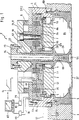
図1は、複数の同心状に配置された磁気コイルおよび永久磁石のリングを備えたターゲットの断面図である。
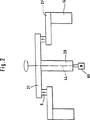
図2は、ステップ状に配置されたヨークプレートの模式図である。
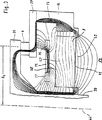
図3は、磁極片および対応する磁力線を示す模式図である。
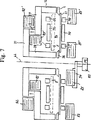
図4〜6は、種々の磁気コイルまたはシールド手段のアレンジメントを有するステップ状のヨークの3種類の模式図である。
図7は、種々の鉄芯のアレンジメントを備えたステップ状に配置されたヨークプレートの模式図である。
基板、例えばコンパクトディスク(CD)27上にコーティングを形成するカソードスパッタリング装置を図1に示す。プロセスを実施するために、スパッタリングカソード2は、カソードスパッタリング装置のチャンバー壁1に設置することができる。カソードはディスク形状の強磁性の第2下側ヨークプレート21’(I)およびそれから離れている第1または上側ヨークプレート21(II)を有する。第2ヨークプレート21’の直径は第1ヨークプレート21の直径よりも大きい。
図1および図2から明らかなように、2つのヨークプレート21、21’はステップ状の形態で、スパッタリングカソード2の縦(または長手)方向の軸44に関して軸対称に配置され、それらは互いに十分に間隔を置いて配置されており、この空間に、環状に配置されるリング状磁石9もまた縦方向の軸44に関して軸対称に配置され得るようになっており、当該空間は相応する高さを有する。この環状に配置されるリング状磁石9はターゲット8に関してN/S極性を有する。
より小さい外径を有する第1(内側)ヨークプレート21は、間接的または直接的に冷却フィンガー74と連結しており、より大きい外径を有する第2ヨークプレート21’は、間接的または直接的に磁極片14と連結している。
図3において、例えば、変化する磁場を形成する手段、または一もしくは複数の第1および第2磁気コイル76、77が第1および第2ヨークプレート21、21’のエリアに設けられている。
図1に示す第1および第2磁気コイル76、77は、第2ヨークプレート21’の下側水平面の下で横方向の同じ平面に配置されている。
第1磁気コイル76はターゲット8の外周55のエリアに設け、第2磁気コイル77は冷却フィンガーまたは冷却ヘッド74のエリアに設けてよい。第1および第2磁気コイル76、77はターゲット8の頂面57または背面側40よりも僅かに上側に設けられる。この点に関して、例えば環状に配置され、第1および/または第2ヨーク21、21’の外周のエリアに設けられるリング状磁石9を、上側または第1ヨークプレート21と下側または第2ヨークプレート21’との間に設け、第1および第2磁気コイル76、77および環状に配置されるリング状磁石9をスパッタリングカソード2の中心軸44に関して同心状に配置すると、好都合である。
スパッタリングカソード2は更に冷却プレート7を含む。絶縁体6は第2ヨークプレート21’と冷却プレート7との間で締着され、ねじ切りしたボルト91によって固定される。
スパッタされるターゲット8は、冷却プレート7の前方に設けられる。第一(外側)および第2(内側)磁気コイル76、77を収容する1つまたは2つの環状のリングチャンバー86が冷却プレート7の背面に設けられ、前記第1および第2磁気コイル76、77はターゲット8の中心軸44に関して同心状となるように配置される。
ヨーク(即ち、第1および第2ヨークプレート)または絶縁体6および冷却プレート7は、ボルト91および冷却フィンガー74によって固定される。絶縁体6はボルト91またはボルト73をヨークから有利に絶縁する。
磁場を形成するための電力供給源は、導線78、79を介して第1および第2磁気コイル76、77に接続することができる。
リング状磁石9は、磁束を導くように第1ヨークプレート21および/または第2ヨークプレート21’ならびに磁極片14に連結され、従って、これらと中空ねじ(20)とともに、完全な磁気閉じ込めを形成する。
磁極片14の下端部はフランジ88を形成し、このフランジに外側マスク(または遮蔽膜)またはアノード4が接続される。磁極片14の高さおよび/またはアノード4の高さは可変である。
基板27はアノード4の下端部に設けられて、ターゲット・スペース84をアノード4およびターゲット表面とともに包囲する。
装置全体に延び、中空のねじ20および冷却フィンガー74を収容する開口部67は、スパッタリングカソード2の中心軸44のエリアに配置される。冷却フィンガー74は図示されていない冷却ラインに接続することができる。
第2ヨークプレート21’(II)は、中空ねじ20と接触することなく、軸方向において中空ねじ20の上端部と近接している。
第2ヨークプレート21’(II)はフランジ22によって冷却ヘッドまたは冷却フィンガー74の上端部に連結され、一方、第1ヨークプレート21(I)は磁極片14に連結され、ボルト73、73’によって固定することができる。
センター・マスクまたはセンター・アノード26は着脱自在に冷却フィンガー74のねじ部分90のフロント面または下端部に連結される。センター・アノード26はターゲット8の中央の凹部に延びており、この中央の凹部はターゲットのフロント面に設けられ、その下端部は外側アノード4または外側マスクとともに、基板27をマスクするリング形状のエリアを形成する。
環状に配置されるリング状磁石9と中心軸44との間の距離は態様に応じて変化させることができる。いずれの場合においても、環状に配置されるリング状磁石9は中心軸44と磁極片14との間に設けられる。図1から明らかなとおり、シールド手段75は第1および第2コイル76、77の間に設けられる。更に、シールド手段75を、第1および第2ヨークプレート21、21’のうちの1つとターゲット8との間に設けることが可能である。シールド手段75は、一方では、第1および第2コイル76、77の鉄芯として作用してそれらの磁場を強くし、他方では、磁場の変動を第1および第2磁気コイルにより比較的小さい電流にてもたらすことができるように、ターゲットのスペース84をリング状磁石9の短絡磁力線からシールドする。このために、シールド手段75は、第1および第2ヨークプレート21、21’の1つおよび/または絶縁体6とターゲット8との間に設けてよい。リング状磁石9はマグネトロンの磁場を形成する作用をする。図3の右側において、カソードまたはスパッタリングマグネトロンの磁力線71は、ターゲットの背面に関して凸形状または平坦、あるいはほぼ平行なコースをとっている。これはまた、有利にはシールド手段75によってもたらされる。そのようなアレンジメントは、非強磁性金属のターゲット、例えば金またはアルミニウムターゲットに特に適している。
第1および第2磁気コイル76、77は環状に配置されたリング状磁石9の僅かに下側に配置される。環状に配置されるリング状磁石9は多数の磁石から成る単一の環状に配置された磁石で形成され得る。
例えば、アルミニウムターゲットまたは金ターゲットとして実施され得るターゲット8の実施態様に応じて、絶対的な磁場の強度を大きくするために、第1の環状に配置されたリング状磁石9に加え、少なくとも1つの環状に配置された別の磁石(図示せず)をリング状磁石9の付近に設けることができる。
図1から明らかなとおり、外側の環状に配置された磁石は、第1および第2磁気コイル76、77よりもターゲットの背面40から離れた位置にある。
図3に示す第1および第2磁気コイル76、77により主磁場は変化させることができ、第1および第2磁気コイル76、77は所定の極性を有し得る。図3では、中心軸44とリング状磁石9との間の半径R9は、図3に従って最適な磁場42を形成し得るように変化させたり、または調節したりすることができる。
第1および第2磁気コイル76、77に供給される電流Iは時間に応じて変化し得る。第1および第2磁気コイル76、77に供給される電流Iまたは第1および第2磁気コイルへの電流供給は、コンピュータ82にプリセットされたプログラムまたはコントロール・カーブによってコントロールすることができ、このために、導線78、79はカレント・ディバイダ80を経由してコンピュータ82と接続している(図1)。従って、ターゲットの表面に全体のスパッタリングプロセスを通じて意図的に影響を及ぼすことができ、同時に、基板27に形成されるコーティングが一定の厚さを有し、コーティングの厚さの偏差を±2%〜3%の範囲とし得ることが確保される。必要とされるコントロール・カーブは経験的に決定され得る。従って、対応するいずれのターゲット、例えば金またはアルミニウムターゲットについても、電流供給に最適なコントロール・カーブを決定することができる。
既に言及したように、ヨークが一体でなく、分割されており、2つの個々のパーツ、即ち、第1(上側)および第2(下側)ヨークプレート21、21’から構成されれば特に好都合である。その場合、これらのパーツは軸対称である2つのディスクから成り、互いに離れていて、それらの間に少なくとも1つのリング状磁石9を設けることができるようになっている。
図4〜図6は、基板27にコーティングを形成するカソードスパッタリング装置の別の態様を示し、この態様において、第1および第2ヨークプレート21、21’または磁極片14および第1および第2磁気コイル76、77はまた異なる形態にて配し又は実施することができる。
図4において、第1および第2ヨークプレート21、21’は、ステップ状となるように形成されている。この場合、図4の第1(上側)ヨークプレートの内側エッジは中空ねじ20と連結され、外側エッジは、環状に配置されたリング状磁石9を介して、段になっている第2(下側の)ヨークプレート21’の内側エッジと連結されている。第2ヨークプレート21’の外側エッジは磁極片14と連結している。
第2磁気コイル77よりも大きな直径を有する第1磁気コイル76は第2(下側)ヨークプレート21’の上方において、第1(上側)ヨークプレート21の外側エッジと第2(下側)ヨークプレート21’の外側エッジとの間に配置される。一方、より小さい直径を有する第2磁気コイル77は第1(上側)ヨークプレート21の下方において、第2(下側)ヨークプレート21’の内側エッジと中空ねじ20との間に配置される。この装置の残りのアレンジメントは、図1の装置のアレンジメントに相応する。
図5の実施態様においても、ヨークは分割されており、それらはまた、異なる直径を有するリング形状の第1および第2ヨークプレート21、21’として実施される。その場合、両方のヨークプレートは、装置のベースに関して水平であり、中心軸44と直交する平面に配置されている。
リング状磁石9は第1および第2ヨークプレート21、21’の間に設けられている。
2つの環状に配置された第1および第2磁気コイル76、77はシールド手段75を囲み、図5では、ターゲット・スペース84に配置されている。
図6の実施態様は、2つのリング状の追加の第1および第2磁気コイル76’、77’を有する第2シールド手段75’が図5と同じアレンジメントでターゲット・スペース84の外側に配置されていることに関して、図5の実施態様とは異なる。
第1および第2磁気コイル76、77または追加の第1および第2磁気コイル76’、77’を有する、ターゲット・スペース84のシールドプレート75またはターゲット・スペース84の外側のシールドプレート75’は、意図的にそしてより最適に磁場をコントロールする作用をする。従って、磁束線のレンズ形状(磁場42参照)がコントロールされる。図3のようなレンズ形状の磁場42を形成することにより、ターゲット8に、有効ガス原子、例えばアルゴン原子をスパッタリングチャンバーにおいてイオン化する作用をする電子の閉じ込めがもたらされる。電子は磁場によってターゲット8の上方に保持され、それらは最適な方法でアノードへ流れることができず、従って、イオン化プロセスに数倍貢献する。従って、一定のコーティング厚さを基板27の表面で達成することが更に確保される。
この説明したアレンジメントによれば、そして電流−時間関数(f(I)=I(t))を考慮すれば、最適な一定のコーティング厚さが達成される。既に言及したように、このアレンジメントにおいて、電流はターゲットの表面に応じて変化させられる。種々の電流を第1および第2磁気コイル76、77に供給することにより、ターゲット表面41の上方でプラズマを放射状に変位させ得る。このことは、プラズマがターゲット8の表面に関して左または右のどちらかに変位させられることを意味する。従って、基板27の表面コーティングは、しっかりと方向付けられてスパッタされ、または成長する。
第1および第2ヨークプレート21、21’をステップ状に形成することにより、非常に簡単な、費用効率のよい全体的なカソードの構成が得られ、簡単な環状に配置される磁石を使用することもできる。磁石は、例えば、リング状磁石ではなく、正方形または矩形の磁石に形成することができ、第1および第2ヨークプレート21および21’の間に容易に設けることができる。リング状磁石はより複雑であり、従って、正方形または矩形の磁石よりもより高価である。
図4において、第1および第2磁気コイル76、77は、図5および6の実施態様の第1および第2磁気コイルよりも、ターゲット8から離れたところに配置される。従って、図1の第1および第2磁気コイルは図5および図6の態様の第1および第2コイル76、77よりも大きくする必要があり、当該磁気コイルには、より多くの電流を供給する必要がある。図1によれば、プラズマは他の実施態様と同じ程度に変位させることができ、その場合、図1のエネルギーの所要量は僅かに高い。
個々の磁気コイルは種々の程度にコントロールすることができ、それらは実施態様に応じて結合してもしなくてもよい。例えば、第1および第2磁気コイル76、77は直列に接続してよい。
既に言及したように、ターゲットの下方または他の場所に配置して磁気コイルを用いることにより、プラズマが内側から外側へ放射状に変位し得るように、ターゲット・スペースにおいて磁場を意図的にコントロールし、そして変化させ得ることは好都合である。従って、エロージョン・グルーブをターゲット上で半径方向に変位させることが可能である。その結果、一方では、連続的に磁場を変化させることによって非常に幅の広いエロージョン・グルーブを形成することができ、他方では、磁場を前後に段階的に切り替えることによって互いに隣合う2つのエロージョン・グルーブを形成することが可能である。
時間に関して変化する磁場を静磁場に追加することによって(またはこれらの2つの磁場を重ねることによって)、一定のコーティング厚さが達成され得る。この可変磁場はコーティング厚さをコーティングサイクルの間、最適化する作用をする。このために、経験的に決定される電流−時間関数が、例えばDE−B−196 54 000においてより詳細に記載されているように、決定される。
ターゲット・スペース84に設けられる図5および図6の第1および第2磁気コイル76、77は、ターゲット・スペース84における磁場をコントロールする作用を主にする。ターゲット・スペース84の外側の磁場をコントロールするために、図6では、追加の第1および第2磁気コイル76’、77’およびシールドプレート75’が設けられている。
この実施態様においても、ヨークを中心軸44に関して垂直に分割することができる。従って、リング状磁石9は磁束が中空ねじ20および磁極片14の間で良好に分布するように配置され得る。従って、ターゲット・スペース84において一様な水平方向の磁場を得ることができる。既に言及したように、この磁場は意図的に第1および第2磁気コイル76、77によってコントロールすることができる。
図7は、軸44を中心として回転可能な4つの鉄芯83、85、92および93のアレンジメントの実施態様を示す。鉄芯85の回転保持手段94を模式的に示す。180°回転した後の鉄芯の位置を、83’、85’、92’および93’で示す。本発明の範囲内においては、当該鉄芯を所望の数だけ設けることができるが、1つまたは2つの鉄芯が好ましい。図示した軸44を中心とする鉄芯の回転によって、ターゲット8の表面のエリアにおける磁場は、時間に応じて変化させられ、極めて均一なコーティング厚さおよび高いターゲットの利用率を達成するために最適化される。
図7の実施態様において示すように、ヨークはまた、分割され軸対称に、第1および第2ヨークプレート21、21’として配置される。更に、例えばリング状磁石9のエリアにおいて、可変磁場を形成できる少なくとも1つの磁気コイル(図示せず)を更に設けてもよい。
本発明の装置は、下記の形態のものを含む。
(形態1)磁極片(14)、ターゲット(8)および少なくとも1つの磁石またはリング状磁石(9)を含み、真空チャンバーに配置し得るスパッタリングカソード(2)によって基板(27)にコーティングを形成するカソードスパッタリングの装置であって、分割されたヨークまたは2つのパーツ(21、21’)で形成されるヨークが設けられていることを特徴とする装置。
(形態2)スパッタリングカソード(2)が円形であり、磁極片(14)および分割されたヨークがスパッタリングカソード(2)にして同心状に配置されている形態1に記載の装置。
(形態3)可変磁場を形成する少なくとも1つの手段(コイル76、77)または少なくとも1つの回転可能な鉄芯(83、85、92、93)が設けられていることを特徴とする形態1または形態2に記載の装置。 The present invention relates to a cathode sputtering apparatus for forming a coating on a substrate (or substrate) with a sputtering cathode (or cathode), the apparatus being provided in a vacuum chamber and including a pole piece, a target, and at least one magnet. If the sputtering cathode is circular, the latter is arranged concentrically with respect to the pole piece, the target and the magnet. The shape of the target sputtering cathode, the pole shoe and the arrangement (or arrangement or arrangement) of the magnets can be matched to the shape of the substrate.
A cathode sputtering apparatus for statically coating a disk-shaped substrate with plasma in a vacuum chamber having at least one opening, the opening being sealed from the outside by disposing a sputtering cathode thereon, Already known (DE 43 15 023 A1). An elastic vacuum seal ring and an annular anode are provided between the cathode and the chamber wall, which radially seal the opening from the outside, the anode having a flat contact surface on the surface facing the cathode. A known sputtering cathode consists of a disk-shaped ferromagnetic yoke and a cooling plate. A disk-shaped insulator is inserted between them. The sputtered target is placed in front of the cooling plate, while the annularly arranged magnet is inserted into a groove (or groove) on the back of the cooling plate. A reverse magnetic field is formed by magnets arranged in an annular shape, which affects the path of the magnetic field lines. As a result, the path of the magnetic field lines of the magnetic field is substantially parallel, lens-shaped, or convex.
In contrast, an object of the present invention is to configure a sputtering cathode so as to obtain an optimal magnetic flow distribution.
In achieving this object, the present invention started from the basic idea of dividing the yoke symmetrically. In the case of a circular sputtering cathode, a divided yoke or a yoke formed from two parts is arranged axisymmetrically with respect to the central axis of the sputtering cathode. Divided or stepped yoke plates allow a very simple and cost-effective cathode configuration and also allow the use of simple, eg annularly arranged magnets. To do. The magnet can be used, for example, as a square or rectangular magnet rather than as a ring magnet and can be easily provided between the yoke plates. Ring magnets are more complex and are therefore more expensive than square or rectangular magnets.
For example, by using a magnetic coil that can be placed below the target or elsewhere, the magnetic field in the target space is intentionally affected so that the plasma can be moved radially from the inside to the outside. Or change the magnetic field. As a result, the erosion grooves can be moved radially on the target, thus forming a very wide erosion groove by continuously changing the magnetic field, or It is possible to form two adjacent erosion grooves by switching stepwise back and forth.
Furthermore, the divided yokes are advantageously provided in the area of the ring-shaped magnet and at least a part of the area forming the variable magnetic field.
In the embodiment of the apparatus of the present invention, it is further possible to provide at least an annularly arranged magnet in the area of the first or second yoke plate or the outer peripheral area of the first or second yoke plate. In an aspect, at least one annular first magnetic coil is provided between the first or second yoke plate and the target or the back surface of the target.
In another aspect of the invention, it is advantageous to provide the first magnetic coil in the area of the outer periphery of the target and the second magnetic coil in the area of the cooling head.
According to a preferred embodiment of the solution according to the invention, the first and second magnetic coils are optionally provided slightly above the top surface (or upper boundary surface) or back surface of the target.
In the present invention, it is particularly important that the first and second magnetic coils are arranged in the same horizontal plane between the first or second yoke plate and the back surface of the target.
Furthermore, the magnets arranged annularly in the outer peripheral area of the first and / or second yoke plate are arranged between the upper or second yoke plate and the lower or first yoke plate or in one plane. Advantageously, it is provided between the first and second yoke plates.
Furthermore, the first and second magnetic coils and the ring-shaped magnet are advantageously arranged concentrically with respect to the central axis of the sputtering cathode.
In this regard, it is advantageous for the ring-shaped magnet to have an outer diameter that is approximately the same size as, or slightly smaller than, or slightly larger than the outer diameter of the first magnetic coil.
Furthermore, it is advantageous to provide the insulator and / or target provided between the target and at least one of the first and second yoke plates with a ring chamber that houses the magnetic coil.
In another aspect of the invention, it is also possible that the first and second magnetic coils have different outer diameters.
In another aspect of the invention, it is advantageous for the second magnetic coil to have an outer diameter that is smaller than the outer diameter of the first magnetic coil.
Furthermore, it is convenient for the ring-shaped magnet to have an NS polarity towards the substrate.
It is also advantageous to provide a shielding means between the first and second magnetic coils.
In another aspect of the apparatus of the present invention, it is further possible to provide shielding means between one of the first and second yoke plates and the target, or between the first and second yoke plates and the substrate.
Furthermore, it is advantageous to provide a shielding means between one of the first and second yoke plates and / or the insulator and the target.
An important advantageous aspect is achieved by placing the first and second yoke plates spaced apart from each other with respect to the central axis in one plane in and / or outside the target space.
Furthermore, the distance between the first and second yoke plates is advantageously approximately equivalent to the height and / or width of the ring magnet.
Furthermore, it is advantageous that the first and second yoke plates are annular plates, that their outer diameters have different dimensions and / or that they are arranged in steps.
In another aspect of the apparatus of the present invention, a first yoke plate having a smaller outer diameter is coupled to a cooling finger and / or indirectly or directly to a hollow screw, and a second yoke plate having a larger outer diameter is indirectly coupled. It is further possible to connect to the pole pieces manually or directly.
In another aspect of the invention, the means for forming the variable magnetic field is advantageously provided in the area of the pole piece.
In a preferred embodiment of the solution according to the invention, it is possible in some cases that the current supplied to the magnetic coil can be varied with time.
In the present invention, the current sent to the magnetic coil or the current supplied to the magnetic coil can be controlled by a control curve or a preset program, and for this purpose the conductors can be controlled by a current divider; or It is particularly important to work with a computer via a current divider.
With regard to the development or arrangement of the present invention, the first magnetic coil is provided in the outer peripheral area of the first yoke plate having a smaller outer diameter, and the second magnetic coil is provided in the inner peripheral area of the second yoke plate. Convenient.
Furthermore, it is advantageous that the two annular first and second magnetic coils are also arranged in steps.
For this purpose, in the area of the substrate, the shielding means arranged in the target space and / or outside the target space is in the same plane as the first and second magnetic coils between the first and second magnetic coils. Conveniently placed.
Another advantageous aspect of the invention includes at least one rotatable iron core.
Further advantages and details of the invention are set forth in the claims and specification and shown in the drawings.
FIG. 1 is a cross-sectional view of a target having a plurality of concentrically arranged magnetic coils and permanent magnet rings.
FIG. 2 is a schematic diagram of yoke plates arranged in a step shape.
FIG. 3 is a schematic diagram showing the pole pieces and the corresponding lines of magnetic force.
4 to 6 are three schematic views of stepped yokes with various magnetic coil or shield arrangements.
FIG. 7 is a schematic view of yoke plates arranged in a step shape with various iron core arrangements.
A cathode sputtering apparatus for forming a coating on a substrate, such as a compact disc (CD) 27, is shown in FIG. In order to carry out the process, the sputtering cathode 2 can be placed on the
As can be seen from FIGS. 1 and 2, the two
The first (inner)
In FIG. 3, for example, means for forming a varying magnetic field, or one or more first and second
The first and second
The first
The sputtering cathode 2 further includes a
The
The yoke (that is, the first and second yoke plates) or the
A power supply for generating a magnetic field can be connected to the first and second
The ring-shaped
The lower end of the
The
An
2nd yokeplatetwenty one'(II) is close to the upper end of the
2nd yokeplatetwenty one'(II) is connected to the upper end of the cooling head or cooling
The center mask or
The distance between the ring-shaped
The first and second
For example, depending on the embodiment of the
As is clear from FIG. 1, the outer annularly arranged magnets are located farther from the
The main magnetic field can be changed by the first and second
The current I supplied to the first and second
As already mentioned, it is particularly advantageous if the yoke is not integral but is divided and consists of two individual parts, namely a first (upper) and a second (lower)
4 to 6 show another embodiment of a cathode sputtering apparatus for forming a coating on the
In FIG. 4, the first and
The first
In the embodiment of FIG. 5, the yokes are also divided and they are also implemented as ring-shaped first and
The ring-shaped
Two annularly arranged first and second
In the embodiment of FIG. 6, a second shield means 75 ′ having two ring-shaped additional first and second
The
According to this described arrangement, the current-time function (f(I)= I(t)), An optimum constant coating thickness is achieved. As already mentioned, in this arrangement the current is varied depending on the surface of the target. By supplying various currents to the first and second
By forming the first and
In FIG. 4, the first and second
Individual magnetic coils can be controlled to varying degrees, which may or may not be combined depending on the embodiment. For example, the first and second
As already mentioned, by using a magnetic coil placed below or elsewhere in the target, the magnetic field is deliberately controlled in the target space so that the plasma can be displaced radially from the inside to the outside, And it is convenient to be able to change. Therefore, the erosion groove can be displaced in the radial direction on the target. As a result, on the one hand, a very wide erosion groove can be formed by continuously changing the magnetic field, and on the other hand, two erosion Grooves can be formed.
By adding a time-varying magnetic field to the static magnetic field (or by superimposing these two magnetic fields), a constant coating thickness can be achieved. This variable magnetic field serves to optimize the coating thickness during the coating cycle. For this purpose, an empirically determined current-time function is determined, for example as described in more detail in DE-B-196 54 000.
The first and second
In this embodiment as well, the yoke can be divided vertically with respect to the
FIG. 7 shows an embodiment of an arrangement of four
As shown in the embodiment of FIG. 7, the yoke is also divided and axisymmetrically arranged as first and
The apparatus of the present invention includes the following forms.
(Form 1) A coating is formed on a substrate (27) by a sputtering cathode (2) comprising a pole piece (14), a target (8) and at least one magnet or ring-shaped magnet (9), which can be placed in a vacuum chamber. Cathode sputtering apparatus, characterized in that it is provided with a split yoke or a yoke formed of two parts (21, 21 ').
(Mode 2) The apparatus according to
(Embodiment 3) At least one means (coils 76, 77) for forming a variable magnetic field or at least one rotatable iron core (83, 85, 92, 93) is provided. The device according to aspect 2.
Claims (30)
(a)第1および第2ヨークプレート(21、21’)が設けられ、それらはスパッタリングカソード(2)において内側から外側へ延在し、第2ヨークプレート(21’)は外側へ最も遠くに延在しており、
(b)前記少なくとも1つの磁石またはリング状磁石(9)は第1および第2ヨークプレート(21、21’)の間に配置されており、
(c)少なくとも1つの回転可能な鉄芯(83、85、92、93)が可変磁場を形成するために設けられており、当該少なくとも1つの回転可能な鉄芯(83、85、92、93)は、半径方向において外側で、もしくは半径方向において内側で、前記少なくとも1つの磁石またはリング状磁石(9)と隣り合う位置に、および/または基板(27)と隣り合い、かつターゲット側とは反対側の位置に、配置されている、ことを特徴とする、装置。Cathode sputtering apparatus comprising a pole piece (14), a target (8) and at least one magnet or ring magnet (9) and forming a coating on a substrate (27) by a sputtering cathode (2) which can be placed in a vacuum chamber Because
(A) First and second yoke plates (21, 21 ') are provided, which extend from the inside to the outside in the sputtering cathode (2), and the second yoke plate (21') is furthest outward. Extended,
(B) the at least one magnet or ring-shaped magnet (9) is disposed between the first and second yoke plates (21, 21 ');
(C) At least one rotatable iron core (83, 85, 92, 93) is provided to form a variable magnetic field, and the at least one rotatable iron core (83, 85, 92, 93) is provided. ) On the outside in the radial direction or on the inside in the radial direction, adjacent to the at least one magnet or ring-shaped magnet (9) and / or adjacent to the substrate (27) and what is the target side A device, characterized in that it is arranged in an opposite position.
(a)第1および第2ヨークプレート(21、21’)がスパッタリングカソード(2)において内側から外側へ延在し、第2ヨークプレート(21’)は外側へ最も遠くに延在しており、
(b)前記少なくとも1つの磁石またはリング状磁石(9)は第1および第2ヨークプレート(21、21’)の間に配置されており、
(c)少なくとも一つの手段(76、77)が可変磁場を形成し、かつ当該手段は、ターゲット(8)の外周(55)のエリアに配置された第1磁気コイル(76)、およびターゲット(8)の内周(54)のエリアに配置された第2磁気コイル(77)を含み、
(d)鉄芯(75)が第1および第2磁気コイル(76、77)と同じ面で2つの磁気コイルの間に配置されている
ことを特徴とする装置。Cathode sputtering apparatus comprising a pole piece (14), a target (8) and at least one magnet or ring magnet (9) and forming a coating on a substrate (27) by a sputtering cathode (2) which can be placed in a vacuum chamber Because
(A) The first and second yoke plates (21, 21 ′) extend from the inside to the outside in the sputtering cathode (2), and the second yoke plate (21 ′) extends the farthest outward. ,
(B) the at least one magnet or ring-shaped magnet (9) is disposed between the first and second yoke plates (21, 21 ');
(C) At least one means (76, 77) forms a variable magnetic field, and the means includes a first magnetic coil (76) disposed in an area of the outer periphery (55) of the target (8), and a target ( 8) including a second magnetic coil (77) disposed in the area of the inner circumference (54);
(D) The iron core (75) is disposed between two magnetic coils on the same plane as the first and second magnetic coils (76, 77).
Applications Claiming Priority (7)
| Application Number | Priority Date | Filing Date | Title |
|---|---|---|---|
| DE19654000.3 | 1996-12-21 | ||
| DE19653999.4 | 1996-12-21 | ||
| DE1996153999 DE19653999C1 (en) | 1996-12-21 | 1996-12-21 | Cathode sputtering apparatus |
| DE1996154007 DE19654007A1 (en) | 1996-12-21 | 1996-12-21 | Apparatus for cathode sputtering for use in coating installations |
| DE19654007.0 | 1996-12-21 | ||
| DE1996154000 DE19654000C1 (en) | 1996-12-21 | 1996-12-21 | Apparatus for cathode sputtering |
| PCT/EP1997/007227 WO1998028779A1 (en) | 1996-12-21 | 1997-12-22 | Device for cathodic sputtering |
Publications (3)
| Publication Number | Publication Date |
|---|---|
| JP2001507079A JP2001507079A (en) | 2001-05-29 |
| JP2001507079A5 JP2001507079A5 (en) | 2005-07-14 |
| JP4422801B2 true JP4422801B2 (en) | 2010-02-24 |
Family
ID=27216979
Family Applications (2)
| Application Number | Title | Priority Date | Filing Date |
|---|---|---|---|
| JP52839598A Expired - Fee Related JP4422801B2 (en) | 1996-12-21 | 1997-12-22 | Cathode sputtering equipment |
| JP52839398A Expired - Fee Related JP4143131B2 (en) | 1996-12-21 | 1997-12-22 | Cathode sputtering apparatus and method |
Family Applications After (1)
| Application Number | Title | Priority Date | Filing Date |
|---|---|---|---|
| JP52839398A Expired - Fee Related JP4143131B2 (en) | 1996-12-21 | 1997-12-22 | Cathode sputtering apparatus and method |
Country Status (5)
| Country | Link |
|---|---|
| US (2) | US6338781B1 (en) |
| EP (2) | EP0946965B1 (en) |
| JP (2) | JP4422801B2 (en) |
| DE (2) | DE59712307D1 (en) |
| WO (3) | WO1998028779A1 (en) |
Families Citing this family (27)
| Publication number | Priority date | Publication date | Assignee | Title |
|---|---|---|---|---|
| KR100421087B1 (en) * | 2001-12-31 | 2004-03-04 | 주식회사 엠피시스템 | automatic moving system and method for parking vehicle |
| JP4470429B2 (en) * | 2002-09-30 | 2010-06-02 | 日本ビクター株式会社 | Magnetron sputtering equipment |
| US7297247B2 (en) * | 2003-05-06 | 2007-11-20 | Applied Materials, Inc. | Electroformed sputtering target |
| US7910218B2 (en) | 2003-10-22 | 2011-03-22 | Applied Materials, Inc. | Cleaning and refurbishing chamber components having metal coatings |
| US7670436B2 (en) | 2004-11-03 | 2010-03-02 | Applied Materials, Inc. | Support ring assembly |
| US8617672B2 (en) | 2005-07-13 | 2013-12-31 | Applied Materials, Inc. | Localized surface annealing of components for substrate processing chambers |
| US7762114B2 (en) * | 2005-09-09 | 2010-07-27 | Applied Materials, Inc. | Flow-formed chamber component having a textured surface |
| US9127362B2 (en) | 2005-10-31 | 2015-09-08 | Applied Materials, Inc. | Process kit and target for substrate processing chamber |
| US8647484B2 (en) | 2005-11-25 | 2014-02-11 | Applied Materials, Inc. | Target for sputtering chamber |
| US20070283884A1 (en) * | 2006-05-30 | 2007-12-13 | Applied Materials, Inc. | Ring assembly for substrate processing chamber |
| US7981262B2 (en) * | 2007-01-29 | 2011-07-19 | Applied Materials, Inc. | Process kit for substrate processing chamber |
| US7942969B2 (en) | 2007-05-30 | 2011-05-17 | Applied Materials, Inc. | Substrate cleaning chamber and components |
| US8968536B2 (en) * | 2007-06-18 | 2015-03-03 | Applied Materials, Inc. | Sputtering target having increased life and sputtering uniformity |
| US20090084317A1 (en) * | 2007-09-28 | 2009-04-02 | Applied Materials, Inc. | Atomic layer deposition chamber and components |
| US7901552B2 (en) * | 2007-10-05 | 2011-03-08 | Applied Materials, Inc. | Sputtering target with grooves and intersecting channels |
| US20090314631A1 (en) * | 2008-06-18 | 2009-12-24 | Angstrom Sciences, Inc. | Magnetron With Electromagnets And Permanent Magnets |
| CN101447274B (en) * | 2008-09-26 | 2011-05-11 | 东莞宏威数码机械有限公司 | Magnetic circuit mechanism, magnetron sputtering cathode therewith and production method thereof |
| ES2374775B1 (en) * | 2009-04-03 | 2013-01-03 | Universidad De Castilla La Mancha | CATHODIC SPRAY UNIT OF CIRCULAR WHITES. |
| DE102010020737A1 (en) * | 2010-05-17 | 2011-11-17 | Oerlikon Trading Ag, Trübbach | Target for spark evaporation with spatial limitation of the propagation of the spark |
| US8294095B2 (en) * | 2010-12-14 | 2012-10-23 | Hermes Microvision, Inc. | Apparatus of plural charged particle beams with multi-axis magnetic lens |
| US8445862B2 (en) * | 2010-12-14 | 2013-05-21 | Hermes Microvision, Inc. | Apparatus of plural charged particle beams with multi-axis magnetic lens |
| US9051638B2 (en) | 2013-03-01 | 2015-06-09 | Poole Ventura, Inc. | In-situ sputtering apparatus |
| WO2014143078A1 (en) * | 2013-03-15 | 2014-09-18 | Poole Ventura, Inc. | In-situ sputtering apparatus |
| TWI527924B (en) * | 2014-02-12 | 2016-04-01 | 兆陽真空動力股份有限公司 | Magnetron with controllable electromagnetic field |
| CN106702336B (en) * | 2015-11-16 | 2019-02-19 | 北京北方华创微电子装备有限公司 | The installing mechanism and magnetron sputtering apparatus of magnetron |
| WO2018175689A1 (en) * | 2017-03-22 | 2018-09-27 | Applied Plasma Equipment | Magnetron sputtering source for insulating target materials |
| WO2019155978A1 (en) * | 2018-02-06 | 2019-08-15 | キヤノンアネルバ株式会社 | Substrate treatment device and substrate treatment method |
Family Cites Families (21)
| Publication number | Priority date | Publication date | Assignee | Title |
|---|---|---|---|---|
| US3956093A (en) * | 1974-12-16 | 1976-05-11 | Airco, Inc. | Planar magnetron sputtering method and apparatus |
| US4336119A (en) * | 1981-01-29 | 1982-06-22 | Ppg Industries, Inc. | Method of and apparatus for control of reactive sputtering deposition |
| JPS60166774A (en) * | 1984-02-09 | 1985-08-30 | Matsushita Electric Ind Co Ltd | Air conditioning machine |
| JPS61231168A (en) * | 1985-04-03 | 1986-10-15 | Sharp Corp | Target for sputtering |
| US4971674A (en) * | 1986-08-06 | 1990-11-20 | Ube Industries, Ltd. | Magnetron sputtering method and apparatus |
| JPS63317664A (en) * | 1987-06-19 | 1988-12-26 | Asahi Chem Ind Co Ltd | Sputtering cathode |
| US4865708A (en) * | 1988-11-14 | 1989-09-12 | Vac-Tec Systems, Inc. | Magnetron sputtering cathode |
| DE69129081T2 (en) * | 1990-01-29 | 1998-07-02 | Varian Associates | Device and method for precipitation by a collimator |
| US5182001A (en) * | 1990-06-13 | 1993-01-26 | Leybold Aktiengesellschaft | Process for coating substrates by means of a magnetron cathode |
| DE4100291C1 (en) * | 1991-01-08 | 1991-10-02 | Leybold Ag, 6450 Hanau, De | |
| US5262030A (en) | 1992-01-15 | 1993-11-16 | Alum Rock Technology | Magnetron sputtering cathode with electrically variable source size and location for coating multiple substrates |
| DE4202349C2 (en) * | 1992-01-29 | 1997-02-13 | Leybold Ag | Cathode sputtering device |
| US5744011A (en) * | 1993-03-18 | 1998-04-28 | Kabushiki Kaisha Toshiba | Sputtering apparatus and sputtering method |
| DE4345403C2 (en) | 1993-05-06 | 1997-11-20 | Leybold Ag | Appts. for cathode sputtering |
| DE4329155A1 (en) | 1993-08-30 | 1995-03-02 | Bloesch W Ag | Magnetic field cathode |
| US5415754A (en) * | 1993-10-22 | 1995-05-16 | Sierra Applied Sciences, Inc. | Method and apparatus for sputtering magnetic target materials |
| DE19623359A1 (en) * | 1995-08-17 | 1997-02-20 | Leybold Ag | Device for coating a substrate by vaporisation of a rotary tubular target |
| US5772861A (en) * | 1995-10-16 | 1998-06-30 | Viratec Thin Films, Inc. | System for evaluating thin film coatings |
| US5863399A (en) * | 1996-04-13 | 1999-01-26 | Singulus Technologies Gmbh | Device for cathode sputtering |
| DE19654000C1 (en) * | 1996-12-21 | 1997-10-30 | Singulus Technologies Gmbh | Apparatus for cathode sputtering |
| US5876576A (en) * | 1997-10-27 | 1999-03-02 | Applied Materials, Inc. | Apparatus for sputtering magnetic target materials |
-
1997
- 1997-12-22 EP EP97953900A patent/EP0946965B1/en not_active Expired - Lifetime
- 1997-12-22 US US09/331,409 patent/US6338781B1/en not_active Expired - Lifetime
- 1997-12-22 WO PCT/EP1997/007227 patent/WO1998028779A1/en active IP Right Grant
- 1997-12-22 JP JP52839598A patent/JP4422801B2/en not_active Expired - Fee Related
- 1997-12-22 EP EP97953901A patent/EP0946966B1/en not_active Expired - Lifetime
- 1997-12-22 DE DE59712307T patent/DE59712307D1/en not_active Expired - Lifetime
- 1997-12-22 JP JP52839398A patent/JP4143131B2/en not_active Expired - Fee Related
- 1997-12-22 US US09/331,453 patent/US6344114B1/en not_active Expired - Lifetime
- 1997-12-22 DE DE59712656T patent/DE59712656D1/en not_active Expired - Lifetime
- 1997-12-22 WO PCT/EP1997/007225 patent/WO1998028777A1/en active IP Right Grant
- 1997-12-22 WO PCT/EP1997/007226 patent/WO1998028778A1/en active Application Filing
Also Published As
| Publication number | Publication date |
|---|---|
| JP4143131B2 (en) | 2008-09-03 |
| US6344114B1 (en) | 2002-02-05 |
| WO1998028779A1 (en) | 1998-07-02 |
| WO1998028777A1 (en) | 1998-07-02 |
| EP0946966A1 (en) | 1999-10-06 |
| EP0946965B1 (en) | 2006-05-17 |
| DE59712656D1 (en) | 2006-06-22 |
| EP0946966B1 (en) | 2005-05-11 |
| EP0946965A1 (en) | 1999-10-06 |
| JP2001507078A (en) | 2001-05-29 |
| JP2001507079A (en) | 2001-05-29 |
| WO1998028778A1 (en) | 1998-07-02 |
| US6338781B1 (en) | 2002-01-15 |
| DE59712307D1 (en) | 2005-06-16 |
Similar Documents
| Publication | Publication Date | Title |
|---|---|---|
| JP4422801B2 (en) | Cathode sputtering equipment | |
| US6440282B1 (en) | Sputtering reactor and method of using an unbalanced magnetron | |
| US6485617B2 (en) | Sputtering method utilizing an extended plasma region | |
| US6444105B1 (en) | Physical vapor deposition reactor including magnet to control flow of ions | |
| US5345207A (en) | Magnet configuration with permanent magnets | |
| JPS5810989B2 (en) | Target profile for sputtering equipment | |
| KR870006231A (en) | Vacuum sputtering device | |
| KR100306956B1 (en) | Sputtering apparatus and method using magnet ring to shape plasma | |
| JPH06235063A (en) | Sputtering cathode | |
| JPH06207271A (en) | Magnetic circuit of permanent magnet for magnetron plasma | |
| JP2912864B2 (en) | Magnetron unit for sputtering equipment | |
| JPH0689446B2 (en) | Thin film forming equipment | |
| US6743342B2 (en) | Sputtering target with a partially enclosed vault | |
| JP2007224343A (en) | Magnetron sputtering device | |
| JPH0941135A (en) | Magnetron sputtering cathode | |
| JPS60255974A (en) | Sputter coating source with plural target rings | |
| JP4685228B2 (en) | Sputtering apparatus and film forming method | |
| JP4680352B2 (en) | Sputtering apparatus and film forming method | |
| JP3766569B2 (en) | Magnetron sputtering equipment | |
| JP2789252B2 (en) | Sputtering equipment using dipole ring type magnetic circuit | |
| JP3000417U (en) | Cathode sputtering equipment | |
| JP2001073134A (en) | Sputtering system and film forming method | |
| KR101629131B1 (en) | Arc-type evaporation source | |
| JP2789251B2 (en) | Sputtering equipment using dipole ring type magnetic circuit | |
| JP2000144413A (en) | Device for coating substrate with thin film |
Legal Events
| Date | Code | Title | Description |
|---|---|---|---|
| A521 | Written amendment |
Free format text: JAPANESE INTERMEDIATE CODE: A523 Effective date: 20041102 |
|
| A621 | Written request for application examination |
Free format text: JAPANESE INTERMEDIATE CODE: A621 Effective date: 20041102 |
|
| A131 | Notification of reasons for refusal |
Free format text: JAPANESE INTERMEDIATE CODE: A131 Effective date: 20070828 |
|
| A601 | Written request for extension of time |
Free format text: JAPANESE INTERMEDIATE CODE: A601 Effective date: 20071127 |
|
| A602 | Written permission of extension of time |
Free format text: JAPANESE INTERMEDIATE CODE: A602 Effective date: 20080121 |
|
| A521 | Written amendment |
Free format text: JAPANESE INTERMEDIATE CODE: A523 Effective date: 20071226 |
|
| A131 | Notification of reasons for refusal |
Free format text: JAPANESE INTERMEDIATE CODE: A131 Effective date: 20080513 |
|
| A521 | Written amendment |
Free format text: JAPANESE INTERMEDIATE CODE: A523 Effective date: 20080724 |
|
| A131 | Notification of reasons for refusal |
Free format text: JAPANESE INTERMEDIATE CODE: A131 Effective date: 20090707 |
|
| A521 | Written amendment |
Free format text: JAPANESE INTERMEDIATE CODE: A523 Effective date: 20091006 |
|
| TRDD | Decision of grant or rejection written | ||
| A01 | Written decision to grant a patent or to grant a registration (utility model) |
Free format text: JAPANESE INTERMEDIATE CODE: A01 Effective date: 20091117 |
|
| A01 | Written decision to grant a patent or to grant a registration (utility model) |
Free format text: JAPANESE INTERMEDIATE CODE: A01 |
|
| A61 | First payment of annual fees (during grant procedure) |
Free format text: JAPANESE INTERMEDIATE CODE: A61 Effective date: 20091207 |
|
| FPAY | Renewal fee payment (event date is renewal date of database) |
Free format text: PAYMENT UNTIL: 20121211 Year of fee payment: 3 |
|
| R150 | Certificate of patent or registration of utility model |
Free format text: JAPANESE INTERMEDIATE CODE: R150 |
|
| FPAY | Renewal fee payment (event date is renewal date of database) |
Free format text: PAYMENT UNTIL: 20131211 Year of fee payment: 4 |
|
| R250 | Receipt of annual fees |
Free format text: JAPANESE INTERMEDIATE CODE: R250 |
|
| R250 | Receipt of annual fees |
Free format text: JAPANESE INTERMEDIATE CODE: R250 |
|
| R250 | Receipt of annual fees |
Free format text: JAPANESE INTERMEDIATE CODE: R250 |
|
| LAPS | Cancellation because of no payment of annual fees |