JP4419627B2 - Video data processing apparatus and video data processing method - Google Patents
Video data processing apparatus and video data processing method Download PDFInfo
- Publication number
- JP4419627B2 JP4419627B2 JP2004082574A JP2004082574A JP4419627B2 JP 4419627 B2 JP4419627 B2 JP 4419627B2 JP 2004082574 A JP2004082574 A JP 2004082574A JP 2004082574 A JP2004082574 A JP 2004082574A JP 4419627 B2 JP4419627 B2 JP 4419627B2
- Authority
- JP
- Japan
- Prior art keywords
- video
- video data
- input
- data processing
- video signal
- Prior art date
- Legal status (The legal status is an assumption and is not a legal conclusion. Google has not performed a legal analysis and makes no representation as to the accuracy of the status listed.)
- Expired - Fee Related
Links
Images


Landscapes
- Studio Circuits (AREA)
Description
本発明は、入力した映像信号で得られる映像データに映像効果を与えて各種効果の付与された映像データを出力する映像データ処理装置及び映像データ処理方法に関し、特に、複数系統の映像信号をミキシングした映像データを出力するビデオミキサー装置等に適したものである。 The present invention relates to a video data processing apparatus and a video data processing method for applying video effects to video data obtained from an input video signal and outputting video data with various effects, and in particular, mixing a plurality of video signals. It is suitable for a video mixer device or the like that outputs the processed video data.
従来、ビデオミキサー装置は、オペレータによって指定された複数の入力系統の映像信号をミックスして映像表示装置にリアルタイムに出力するものであり、例えばコンサートや各種イベントにおいてバック映像などを演出する際に用いられる。その際、入力系統の選択、複数入力系統の映像データの混合比の設定、各入力系統の映像データに付与する視覚的効果(映像効果)の設定等が行われる。なお、これらの設定による映像の各加工仕様の一つ一つ、あるいはこの設定により加工処理された映像自体を「シーン」という。このようなのもとして、例えば特開2002−262179号公報に開示されたものがある。
上記のような従来のビデオミキサー装置によれば、混合や加工の元となる映像信号を複数系統用いることでバラエティに富んだ映像が得られる。しかしながら、複数の入力系統に映像信号を入力する際に、複数の映像再生装置や複数のメディアを同時再生したり、あるいは、複数の映像信号を異なる記憶装置から読み出すなど、入力ソースを用意する作業が煩雑になるという問題があった。また、あるシチュエーションで特定の組み合わせの複数の映像を用いて加工再生し、これを別のシチュエーションで、多少変更して再度加工再生したい場合も、同じ組み合わせの複数の映像ソースを用意する必要があり、メディア等を管理するのが煩雑になるという問題がある。 According to the conventional video mixer apparatus as described above, a wide variety of images can be obtained by using a plurality of systems of video signals as a source of mixing and processing. However, when inputting video signals to multiple input systems, work to prepare input sources, such as simultaneously playing multiple video playback devices and multiple media, or reading multiple video signals from different storage devices There was a problem that became complicated. Also, if you want to process and play back multiple images in a specific situation using a specific combination, and then change this in another situation and reprocess it again, you need to prepare multiple video sources with the same combination. There is a problem that managing the media and the like becomes complicated.
本発明は、複数の映像を混合、加工する映像データ処理装置において、複数の動画を扱う際の作業性を良くするとともに映像ソースの管理をし易くすることを課題とする。 An object of the present invention is to improve workability when handling a plurality of moving images and to facilitate management of a video source in a video data processing apparatus that mixes and processes a plurality of videos.
請求項1の映像データ処理装置は、映像信号取得手段で取得した、1つのフレームに複数の動画を記録した映像信号から、範囲確定手段で確定させた一定範囲の映像データを抽出し、該抽出した映像データを一定の大きさの描画面積になるようにして出力するようにした。一定の大きさの描画面積とは画面全体の描画面積に限らず、画面の一部に窓のような描画区域を設けてそこに描画するような描画面積でもよい。 The video data processing device according to claim 1 extracts video data of a certain range determined by the range determination unit from the video signal obtained by recording a plurality of moving images in one frame acquired by the video signal acquisition unit, The video data is output so that the drawing area has a certain size. The drawing area of a certain size is not limited to the drawing area of the entire screen, but may be a drawing area in which a drawing area such as a window is provided in a part of the screen and drawn there.
請求項2の映像データ処理装置は、請求項1に加えて、制御手段により、映像データ抽出手段で抽出する映像を、特定のタイミングで切り換えたり、描画制御を行うようにした。特定のタイミングは、例えば、ユーザが操作する操作子変化(実施形態における「シーンメモリスイッチ」の切り換えに対応する変化)や、切り換えのシーケンスデータ(実施形態における「ストリームデータ」に対応するデータ)による指示を行うものなどである。 According to a second aspect of the present invention, in addition to the first aspect, the video data processing apparatus switches the video extracted by the video data extracting means at a specific timing or performs drawing control by the control means. The specific timing is determined by, for example, a change in the operator operated by the user (change corresponding to switching of the “scene memory switch” in the embodiment) or switching sequence data (data corresponding to “stream data” in the embodiment). Something that gives instructions.
請求項3の映像データ処理方法は、映像信号を入力して複数の映像入力チャンネルで該映像データに各種の加工を施して出力する映像データ処理装置における映像データ処理方法であって、1つのフレームに複数の動画を記録した映像信号を供給する映像記録媒体を用い、この映像信号を複数の映像入力チャンネルに入力し、各映像入力チャンネルにて映像信号の複数の動画から1つの動画の範囲を選択的に抽出して該抽出した動画の映像データを出力する。
A video data processing method according to
好適な映像データ処理装置として、請求項1の映像データ処理装置であって、範囲確定手段における該範囲確定手段が確定する一定範囲を例えばユーザ等により設定できるようにしてもよい。この例によれば、請求項1と同様な効果に加え、1つの映像ソースに含まれる動画の数が異なるような映像ソースでも、映像ソースに応じて一定範囲を設定することにより容易に対応することができる。
As a suitable video data processing device, the video data processing device according to
好適な映像データ処理装置として、請求項2の映像データ処理装置であって、同時に複数の映像データを抽出して、任意の配列で同時に描写するものであり、また、抽出した映像データのそれぞれは、任意の映像効果(明暗、モザイク、白黒/カラー、彩度等)を付加して描写するものでもよい。
The video data processing apparatus according to
本発明の請求項1または請求項3によれば、複数の映像を混合、加工する映像データ処理装置において、1つの映像ソースで複数の動画を供給することができ、これらの動画から所望のものを切り出して各種処理を行うことができるので、複数の映像ソースを必要としないなど、複数動画を扱う際の作業性が良くなり、また、映像ソースの管理もし易くなる。また、複数の動画を一定の大きさイベントに拡大して表示することが可能となる。 According to the first or third aspect of the present invention, in a video data processing apparatus that mixes and processes a plurality of videos, a plurality of videos can be supplied from one video source, and a desired one can be selected from these videos. Since various processes can be performed by cutting out a plurality of video sources, workability when handling a plurality of moving images is improved, such as not requiring a plurality of video sources, and video sources can be easily managed. In addition, a plurality of moving images can be enlarged and displayed in a certain size event.
請求項2によれば、請求項1と同様な効果に加え、1つの映像ソースで複数の動画を供給できるものにおいて簡単な操作でバラエティに富んだ映像が得られる。 According to the second aspect, in addition to the same effect as the first aspect, a variety of videos can be obtained by a simple operation in the case where a plurality of moving images can be supplied by one video source.
以下、図面を参照して本発明の一実施形態について説明する。図1は実施形態の映像データ処理装置における操作パネルを示す図である。この映像データ処理装置はビデオミキサー装置であり、ビデオカメラ、ビデオテープレコーダ、DVD(Digital Versatile Disk)、パーソナルコンピュータ等の外部の映像機器から複数系統の映像信号を入力することができる。また、一つの入力系統の映像信号を処理単位とする映像入力チャンネルをch1,ch2,ch3,ch4の4チャンネル備えており、4つの映像入力チャンネルの各々に対して任意の系統の映像信号を割り当てることができる。そして、各映像入力チャンネルでは、操作子の操作によるパラメータ等の設定により、映像信号から得られる映像データの加工を行うことができ、この加工された映像データはミキシングされて、テレビモニタ、プロジェクタ、パーソナルコンピュータ等の映像表示装置に出力される。 Hereinafter, an embodiment of the present invention will be described with reference to the drawings. FIG. 1 is a diagram illustrating an operation panel in the video data processing apparatus according to the embodiment. This video data processing device is a video mixer device, and can input a plurality of video signals from an external video device such as a video camera, a video tape recorder, a DVD (Digital Versatile Disk), or a personal computer. In addition, four video input channels ch1, ch2, ch3, and ch4 are provided with a video signal of one input system as a processing unit, and an arbitrary system of video signals is assigned to each of the four video input channels. be able to. In each video input channel, the video data obtained from the video signal can be processed by setting parameters or the like by operating the operation element, and the processed video data is mixed to a television monitor, a projector, It is output to a video display device such as a personal computer.
また、映像データの加工のための各種パラメータ等の設定データ(1チャンネルまたは複数チャンネル分)をシーンメモリスイッチに対応させて一つのシーンデータとして記憶することができる。さらに、記憶したシーンデータを読み出したりパラメータ等を設定しながら、複数のシーンデータの時系列なセットからなるストリームデータを作成し、このストリームデータをストリームメモリスイッチに対応させて記憶することができる。このストリームデータは映像の切り換えタイミング(特定のタイミング)を設定するものであり、このストリームメモリスイッチはストリームデータにより映像を順次更新して再生する際に用いる。 Also, setting data (for one channel or a plurality of channels) such as various parameters for processing video data can be stored as one scene data in association with the scene memory switch. Furthermore, while reading the stored scene data and setting parameters, etc., stream data consisting of a time series set of a plurality of scene data can be created, and this stream data can be stored in correspondence with the stream memory switch. This stream data sets the switching timing (specific timing) of the video, and this stream memory switch is used when the video is sequentially updated and reproduced by the stream data.
ここで、映像信号は、図示しないリアパネルに配設されたIn1,2,3,4及びExt(エクスターナル)の5つの入力端子からアナログのコンポジット形式で入力することができるが、後述のように、一つの入力端子から1系統の映像信号(1つの映像ソース)を入力し、この1系統の映像信号から複数種類(この実施形態では4種類)の映像を得ることで本発明を実施する。なお、この1系統の映像信号から複数種類の映像を得るモードを、本明細書では「単一ソースモード」という。 Here, the video signal can be input in an analog composite format from five input terminals of In1, 2, 3, 4 and Ext (external) arranged on a rear panel (not shown). The present invention is implemented by inputting one system of video signal (one video source) from one input terminal and obtaining a plurality of types (four types in this embodiment) of video from this one system of video signals. Note that a mode in which a plurality of types of video are obtained from this one-line video signal is referred to as a “single source mode” in this specification.
図1において、各映像入力チャンネル(ch1〜ch4)はそれぞれ同じ操作子11〜19を備えている。11はその映像入力チャンネルへの入力映像信号を選択する入力セレクトスイッチであり、各映像入力チャンネルごとに、In1,2,3,4及びExtの5入力から任意に1つを選択する。12はそのチャンネルの使用/不使用(オン/オフ)を設定するチャンネルオンスイッチ、13はポジ表示とネガ表示を切り替えるネガスイッチである。14は輝度信号と色差信号のゲインを調整するトリムボリューム、15は色相を調整する色相ボリューム、16は色ゲイン(彩度)を調整する色ゲインボリューム、17は後述のチャンネル共通制御部のパラメータをアサイン可能なアサイナブルボリュームである。18は映像入力チャンネルの映像信号をクロスフェーダ42のA入力/B入力の何れに割り当てるかあるいは「スルー」に設定するかを選択するアサインスイッチである。19はその映像入力チャンネルの映像信号の出力レベルを設定するチャンネルフェーダである。
In FIG. 1, each video input channel (ch1 to ch4) includes the
21〜26、31〜38は各映像入力チャンネルにさらに多様なパラメータを設定するチャンネル共通制御部の操作子である。21はパラメータ値を変化させるロータリーエンコーダ、22はこのパラメータ値を初期値に戻すイニシャライズボタン、23はこのパラメータ値の設定対象の映像入力チャンネルを選択するチャンネルセレクトスイッチである。24はパラメータ値を微調整したり2つのシーンの間を補間しながら変更するためのジョグシャトル、25はジョグシャトル24で補間変更する2つのシーンをアサインするアサインスイッチ、26はジョグシャトル24による補間変更の有効/無効を選択するスイッチである。
Reference numerals 21 to 26 and 31 to 38 are operators of a channel common control unit for setting various parameters for each video input channel. Reference numeral 21 denotes a rotary encoder that changes the parameter value, 22 denotes an initialize button that returns the parameter value to an initial value, and 23 denotes a channel select switch that selects a video input channel for setting the parameter value.
31〜38はロータリーエンコーダ21に対してアサインするパラメータの種類を選択するためのパラメータスイッチである。スイッチ31は映像の表示位置を決めるパラメータを選択し、スイッチ32は画面分割数を決めるパラメータを選択し、スイッチ33は反転表示の態様を決めるパラメータを選択する。スイッチ34は映像のフレームを間引く割合を決めるパラメータを選択し、スイッチ35は映像の表示サイズを決めるパラメータを選択し、スイッチ36は映像の歪みの態様を決めるパラメータを選択する。スイッチ37は選択チャンネルの映像をレイヤーとして表示するかしないか(レイヤー表示のオン/オフ)を選択し、スイッチ38はパラメータ値をシフトするスイッチである。
Reference numerals 31 to 38 denote parameter switches for selecting the type of parameter to be assigned to the rotary encoder 21. The switch 31 selects a parameter for determining a video display position, the
41は映像信号の出力時にリアルタイムに映像効果を与えるリアルタイムシーン機能に関する操作子郡であり、複数のシーンデータの各記憶領域に対応するシーンメモリスイッチや、プリセットシーンを呼び出すパターンスイッチ等を備えている。42は、異なる映像入力チャンネルの前記アサインスイッチ18で「A入力」,「B入力」に割り当てられた2つの映像信号を合成し、その際の混合比(0〜1)を設定するクロスフェーダである。43はミキシングされた映像信号の出力レベルを調整するマスタフェーダである。その他に、クロスフェード方法を選択するスイッチ、ストリームデータにより映像を順次更新して再生する機能に関する再生ボタン、停止ボタン等を備えている。
中央の1Aの部分はシーンデータの削除や設定のキャンセル等の操作を行うシステム制御部である。このシステム制御部1Aにはモードスイッチ1と設定スイッチ2が配設されており、このモードスイッチ1と設定スイッチ2により「単一ソースモード」の設定及びモード選択を行う。例えば、各映像入力チャンネルについて、次のように画像面の一定範囲を確定させる範囲確定操作を行う。モードスイッチ1の操作で「単一ソースモード」を選択し、スイッチ35とロータリーエンコーダ21で映像の表示サイズを決めるとともに、スイッチ31とロータリーエンコーダ21で映像の表示位置を決め、設定スイッチ2の操作により、画像面の一定範囲を確定させる。そして、「単一ソースモード」からぬけて通常のモードに入るときはモードスイッチ1を操作し、「単一ソースモード」に入るときはモードスイッチ1を操作する。この「単一ソースモード」にすると、各映像入力チャンネルはそのチャンネルに選択した映像信号について、上記一定範囲の映像信号を入力信号として扱うようになる。
The
図2は上記範囲確定操作による設定の一例を示す図である。まず、図2(A) は実施形態における単一ソースモードで用いる原映像信号による原画像の例であり、1つのフレームfを縦横の4つに分割して、各分割領域に動画A,動画B,動画C,動画Dの4つの動画を記録したものである。この映像信号は各映像入力チャンネル(ch1〜ch4)に共通に入力するが、各映像入力チャンネル毎にこの映像信号からそれぞれ1つの動画を選択する。 FIG. 2 is a diagram showing an example of the setting by the range determining operation. First, FIG. 2A is an example of an original image by an original video signal used in the single source mode in the embodiment. One frame f is divided into four vertically and horizontally, and a moving image A and a moving image are divided into each divided region. Four moving images B, moving image C, and moving image D are recorded. This video signal is input in common to each video input channel (ch1 to ch4), and one moving image is selected from this video signal for each video input channel.
この一つの動画を選択する具体的な手法が前記範囲確定操作であり、各映像入力チャンネル(ch1〜ch4)における表示サイズのパラメータと表示位置のパラメータを設定する。例えば第1の映像入力チャンネルch1で動画Aを選択する場合、図2(B) に示したように原映像信号の画像を縦横2倍に拡大するように表示サイズを設定する。画像の左上隅を画像の基準点とすると、この第1の映像入力チャンネルch1における表示位置のパラメータは通常の設定(移動しない設定)であり、拡大された動画Aの画面が、表示画面に対応する仮想的な画面Wにそのまま一致する。そして、そのまま映像入力チャンネルch1の映像信号を出力すれば動画Aが表示画面一杯に表示される。 A specific method for selecting this one moving image is the range determination operation, and the display size parameter and the display position parameter in each video input channel (ch1 to ch4) are set. For example, when the moving image A is selected in the first video input channel ch1, the display size is set so that the image of the original video signal is enlarged two times vertically and horizontally as shown in FIG. Assuming that the upper left corner of the image is the reference point of the image, the parameter of the display position in the first video input channel ch1 is a normal setting (setting that does not move), and the enlarged video A screen corresponds to the display screen. It matches the virtual screen W to be matched as it is. If the video signal of the video input channel ch1 is output as it is, the moving image A is displayed on the full display screen.
また、第2の映像入力チャンネルch2で動画Bを選択する場合、図2(C) に示したように原映像信号の画像を縦横2倍に拡大するように表示サイズを設定する。この第2の映像入力チャンネルch2における表示位置は、映像を左に1画面分(拡大画像の半分)だけ移動するように設定する。これにより拡大された動画Bの画面が画面Wに一致する。同様に、第3の映像入力チャンネルch3で動画Cを選択する場合、縦横2倍に拡大するように表示サイズを設定するとともに、表示位置は上に1画面分だけ移動するように設定する。また、第4の映像入力チャンネルch4で動画Dを選択する場合、縦横2倍に拡大するように表示サイズを設定するとともに、表示位置は左に1画面分、上に1画面分だけ移動するように設定する。 Further, when the moving image B is selected in the second video input channel ch2, the display size is set so that the image of the original video signal is enlarged two times vertically and horizontally as shown in FIG. The display position in the second video input channel ch2 is set so that the video is moved to the left by one screen (half of the enlarged image). As a result, the screen of the enlarged video B matches the screen W. Similarly, when the moving image C is selected in the third video input channel ch3, the display size is set so as to be doubled vertically and horizontally, and the display position is set so as to move upward by one screen. In addition, when the moving image D is selected in the fourth video input channel ch4, the display size is set so as to be doubled vertically and horizontally, and the display position is moved by one screen left and by one screen upward. Set to.
このように、各映像入力チャンネル(ch1〜ch4)における表示サイズのパラメータと表示位置のパラメータを設定することが、画像面の一定範囲を確定させることに相当し、各設定したパラメータを「単一ソースモード」時の設定値として記憶しておく。この場合、各設定したパラメータによる表示サイズ、表示位置を各映像入力チャンネルにおける新たな初期値とし、その上で通常の映像信号の加工等を行うことにより、選択した4つの動画をあたかも4つの映像ソースとして入力したかのように、処理することができる。 As described above, setting the display size parameter and the display position parameter in each video input channel (ch1 to ch4) corresponds to determining a certain range of the image plane. It is memorized as a set value in “source mode”. In this case, the display size and the display position according to the set parameters are set as new initial values for each video input channel, and normal video signal processing or the like is performed on the display size and display position. It can be processed as if it were entered as a source.
上記の説明はパラメータによって表示サイズと表示位置を設定することに対応した説明であり、動画を選択してその映像データを得る処理は、実際には確定された範囲の映像データに対してドットを補間して映像データを切り出すという処理を行っている。図3はこの映像データの切り出しの例を示す図であり、図3(A) の原映像データから動画Bを切り出す場合、図3(B) のように動画Bの部分だけ拡大して図3(C) のように拡大した一つの動画を得る。図4は拡大時のドットの補間を説明する図であり、(i) のように「a1〜c5」の15のドットからなるものとした場合、各走査線となる「a1〜a5」、「b1〜b5」、「c1〜c5」の各ドットをコピーして各々のドットの横に挿入し、(ii)のように走査線方向に2倍に拡大する、次に、拡大した走査線「a1,a1〜a5」、「b1,b1〜b5」、「c1,c1〜c5」をそれぞれコピーして次の走査線との間に挿入し、(iii) のように縦方向に2倍に拡大する。このようにして、確定された範囲の映像データに対して切り出しを行う。 The above description is an explanation corresponding to setting the display size and display position by parameters, and the process of selecting a moving image and obtaining the video data is actually to set dots on the video data in the determined range. Interpolation is performed to cut out video data. FIG. 3 is a diagram showing an example of cutting out the video data. When the moving image B is cut out from the original video data in FIG. 3 (A), only the portion of the moving image B is enlarged as shown in FIG. 3 (B). Get one enlarged movie as shown in (C). FIG. 4 is a diagram for explaining dot interpolation at the time of enlargement. When it is composed of 15 dots “a1 to c5” as shown in (i), “a1 to a5”, “ The dots “b1 to b5” and “c1 to c5” are copied and inserted beside each dot, and are enlarged twice in the scanning line direction as shown in (ii). Next, the enlarged scanning line “ a1, a1 to a5 "," b1, b1 to b5 ", and" c1, c1 to c5 "are copied and inserted between the next scanning lines and doubled vertically as shown in (iii) Expanding. In this way, the video data in the determined range is cut out.
図5は実施形態のビデオミキサー装置のブロック図である。信号処理部10はCPU10a、RAM10b、ROM10c、タイマ10dで構成されており、CPU10aはROM10cに格納された所定のプログラムを実行し、RAM10bの各種レジスタ、フラグ等を含むワーキングエリアを使用して全体の制御を行う。タイマ10dは各種プログラムの実行中に時間を計時するものである。入力インターフェース(I/F)20は接続した映像機器100から映像信号を取り込み、出力インターフェース30は接続した画像表示装置200へ映像信号を出力して表示する。設定操作子群40は前記操作パネルの各種操作ある。表示器50は液晶パネル等で構成されており、該ビデオミキサー装置の設定状態や、映像の簡易表示等を行う。記憶装置60は、作成したシーンデータやストリームデータ、機器の設定状態、あるいは各種のプログラムを記憶する。
FIG. 5 is a block diagram of the video mixer apparatus of the embodiment. The
図6は実施形態のビデオミキサー装置の要部信号経路を示す図である。この信号経路は、前記各種操作子操作に応じた信号処理部10、入力インバータ20及び出力インターフェース30による機能を、等価な電気回路として図示したものである。なお、Extの系統は省略してある。
FIG. 6 is a diagram illustrating a signal path of a main part of the video mixer apparatus according to the embodiment. In this signal path, the functions of the
各映像入力チャンネル(ch1〜ch4)において、スイッチ部Aは入力セレクトスイッチ11により切替え設定され、4つの入力端子T1〜T4から入力する映像を選択する。なお、「単一ソースモード」の時は、各チャンネルにおいて、映像機器100を接続した一つの入力端子(例えばT1)を選択する。画質制御部Bは、ネガスイッチ13、トリムボリューム14、色相ボリューム15、色ゲインボリューム16等の操作に応じて、入力された映像信号の画質を調整する。画像位置制御部Cは、ロータリーエンコーダ21あるいはアサイナブルボリューム17の操作に応じて、表示位置、表示サイズ、歪み等を調整し、ボリュームDは、チャンネルフェーダ19の操作により映像信号の出力レベルを設定する。オンオフスイッチEは、チャンネルオンスイッチ12の操作により映像信号の出力/非出力を切り替え、スイッチ部Fは、クロスフェーダアサインスイッチ18の操作に応じて映像信号を「A入力」,「B入力」,「スルー」に選択的に出力する。2連ボリュームGは、クロスフェーダ41の操作に応じて、「A入力」の映像信号と「B入力」の映像信号を、設定された混合比に応じたレベルで出力し、この2連ボリュームGの各出力信号はミキシングされて画像出力チャンネルOUTに出力される。また、「スルー」の映像信号はそのまま画像出力チャンネルOUTに出力される。
In each video input channel (ch1 to ch4), the switch section A is switched by the input
画像位置制御部Cは、「単一ソースモード」の時は、各映像入力チャンネルに設定されている前記表示サイズ、表示位置のパラメータに基づいて位置制御する。すなわち、選択した一つの動画の範囲の映像データを、あたかも一つの入力端子からの映像信号によるものであるかのように処理を行う。これにより、「単一ソースモード」の時に、通常モードと同様な映像の加工を行ったり、請求項2に対応して特定のタイミングで切り換えたり描画制御を行うために、シーンデータあるいはストリームデータ等で再生を行うと、単一ソースで得られた例えば4つの動画の映像を、4つの入力端子からそれぞれ入力された複数の映像信号に対すると同様な処理を行うことができる。また、「単一ソースモード」の時、映像の加工を行わないでチャンネルのオン/オフあるいはチャンネルの切り換えをすることにより、単一ソースで得られた4つの動画を、切り換えながら同時再生することもできる。 In the “single source mode”, the image position control unit C controls the position based on the display size and display position parameters set for each video input channel. That is, the video data in the range of one selected moving image is processed as if it were the video signal from one input terminal. Thus, in the “single source mode”, scene data or stream data is processed in order to perform image processing similar to that in the normal mode, or to perform switching or drawing control at a specific timing corresponding to claim 2. When playback is performed with the above, for example, four moving picture images obtained from a single source can be processed in the same manner as a plurality of video signals respectively input from four input terminals. Also, when in “Single Source Mode”, four videos obtained with a single source can be played simultaneously while switching, by turning on / off the channel or switching the channel without processing the video. You can also.
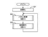
図7は実施形態における制御プログラムのメインルーチンのフローチャート、図8はパネル処理のフローチャート、図9は処理実行のフローチャートであり、同図に基づいて実施形態の動作を説明する。電源の投入によって図7のメインルーチンの処理を開始すると、ステップS1の初期化の処理でRAM10bの内容をクリアするとともに初期の設定を行う。次に、ステップS2で図8のパネル処理を行い、ステップS3で図9の処理実行を行ってステップS2に戻る。
FIG. 7 is a flowchart of the main routine of the control program in the embodiment, FIG. 8 is a flowchart of panel processing, and FIG. 9 is a flowchart of processing execution. The operation of the embodiment will be described based on FIG. When the processing of the main routine of FIG. 7 is started by turning on the power, the contents of the
図8のパネル処理では、ステップS11でパネル入力(スイッチ操作)の有無を判定し、パネル入力がなければそのままメインルーチンに復帰し、パネル入力があった場合、すなわちユーザによって何らかの設定操作子が操作されたときステップS12以降でパネル入力による各種指示の内容に応じた処理を行う。ステップS12で映像の選択変更の指示があると、ステップS13で処理部の設定を変更して元のルーチンに復帰する。 In the panel processing of FIG. 8, it is determined whether or not there is a panel input (switch operation) in step S11. If there is no panel input, the process returns to the main routine as it is, and if there is a panel input, that is, some setting operator operates by the user. When this is done, processing corresponding to the contents of various instructions by panel input is performed in step S12 and subsequent steps. If there is an instruction to change the video selection in step S12, the setting of the processing unit is changed in step S13, and the process returns to the original routine.
このステップS13では、外部から送信されてくる映像に対して映像入力チャンネルを指定、または記憶装置に記憶されている映像データの指定の、どれかをユーザによる選択を受け付ける処理を行う。また、特定された映像からどの範囲を切り出すかの指定を受ける。また、この切り出した映像に対してどのような効果処理を行うかの指定を受ける。さらに、上記特定して処理した映像を複数受け付け、これらの映像の配置の指定を受ける。すなわち、前記操作パネルの操作子の操作に応じた加工処理に関する指定を受ける。 In step S13, a process of accepting a selection by the user from one of designation of a video input channel or designation of video data stored in a storage device for a video transmitted from the outside is performed. In addition, it receives designation of which range is cut out from the specified video. In addition, it receives designation of what kind of effect processing is to be performed on the clipped video. Further, a plurality of the specified and processed videos are received, and designation of the arrangement of these videos is received. That is, a designation relating to the processing according to the operation of the operator on the operation panel is received.
ステップS14でシーンの切り換え指示があると、ステップS15で、シーンメモリスイッチ等により選択されたシーンを読み出し、ステップS13で処理部の設定を変更して元のルーチンに復帰する。なお、この場合もステップS13では、選択されたシーンの内容に応じた前記の加工処理に関する指定を受ける。 If there is a scene switching instruction in step S14, the scene selected by the scene memory switch or the like is read in step S15, and the setting of the processing unit is changed in step S13 to return to the original routine. In this case as well, in step S13, designation regarding the above-described processing according to the content of the selected scene is received.
ステップS16で映像の出力開始指示があれば、ステップS17で、開始フラグを立てるなど映像の出力開始に関する設定を行って元のルーチンに復帰する。ステップS18で映像の出力停止指示があれば、ステップS19で、停止フラグを立てるなど映像の出力停止に関する設定を行って元のルーチンに復帰する。ステップS20では、例えばシーンデータの作成に関する指示など、その他の指示に関する処理を実行し、元のルーチンに復帰する。 If there is a video output start instruction in step S16, in step S17, settings relating to the start of video output, such as setting a start flag, are made, and the process returns to the original routine. If there is a video output stop instruction in step S18, settings relating to video output stop are made in step S19, such as setting a stop flag, and the process returns to the original routine. In step S20, for example, a process related to other instructions such as an instruction related to creation of scene data is executed, and the process returns to the original routine.
図9の処理実行では、ステップS21で、開始フラグが立っているか否かを判定し、立っていなければ映像開始中でないのでステップS28に進み、開始フラグが立っていいれば、映像開始中であるのでステップS22以降で映像の加工及び出力処理を行う。ステップS22では未処理の映像があるかを判定する。この判定は、複数の映像を合成して出力する場合に一つ一つの映像について、順次映像データの切り出し及び加工を行うためのものであり、全ての映像データについてステップS23,S24,S25の処理を終了するとステップS26に進む。なお、使用する映像が一つしかなければ、ステップS23,S24,S25の処理を一度行ってステップS26に進む。 In the process execution of FIG. 9, it is determined in step S21 whether or not the start flag is set. If it is not set, the video is not started, so the process proceeds to step S28. If the start flag is set, the video is started. Therefore, image processing and output processing are performed in and after step S22. In step S22, it is determined whether there is an unprocessed video. This determination is for sequentially cutting out and processing video data for each video when a plurality of videos are synthesized and output, and the processing of steps S23, S24, and S25 is performed for all video data. When finished, the process proceeds to step S26. If there is only one video to be used, the processes of steps S23, S24, and S25 are performed once, and the process proceeds to step S26.
ステップS23では、例えは映像入力チャンネルch1とch2との映像データとか、映像入力チャンネルch1の映像データと記憶装置に記憶された映像データとか、設定されている映像データを取得する。ステップS24では映像データの切り出しを行う。例えば、もともと取得した映像が縦2枚横2枚からなる4枚の映像(例えば図3(A) )であった場合、右上の映像(動画B)のみをつかうのであれば、左上の映像と下の映像を取り除いた右上のみの映像データを作り出す。ステップS25では切り出した映像データの加工処理を行う。例えば、図3、図4で説明したと同様な拡大処理(ドットの補間)を行う。また、画面の明るさや色合いや、白黒化、歪み、モザイク化などの映像効果をつけたりもする。 In step S23, for example, the video data of the video input channels ch1 and ch2, the video data of the video input channel ch1 and the video data stored in the storage device, or the set video data is acquired. In step S24, the video data is cut out. For example, if the originally acquired video is 4 videos consisting of 2 vertically and 2 horizontally (for example, FIG. 3 (A)), if only the upper right video (video B) is used, Only the upper right image data is created by removing the lower image. In step S25, the cut out video data is processed. For example, enlargement processing (dot interpolation) similar to that described with reference to FIGS. 3 and 4 is performed. It also adds image effects such as screen brightness and color, black and white, distortion, and mosaic.
そして、ステップS26では、ステップS23,S24,S25で処理した映像データについて映像の合成を行い、ステップS27で、合成した映像データを出力し、ステップS28に進む。ステップS28では、停止フラグが立っているか否かを判定し、立っていなければ停止の指示がないのでそのまま元のルーチンに復帰し、停止フラグが立っていいれば、停止の指示がたったので、ステップS29で、開始フラグと停止フラグを下ろして処理を停止させ、元のルーチンに復帰する。 In step S26, the video data processed in steps S23, S24, and S25 is synthesized. In step S27, the synthesized video data is output, and the process proceeds to step S28. In step S28, it is determined whether or not a stop flag is set. If it is not set, there is no stop instruction, so the process returns to the original routine. If the stop flag is set, a stop instruction is given. In S29, the start flag and the stop flag are lowered to stop the process, and the process returns to the original routine.
このように、同時再生を目的にして作成した複数の映像を例えば一枚の記録ディスクなどのメディアで供給することができ、取り扱いが容易で、複数の動画を扱う際の作業性もよくなる。また映像ソースの管理もしやすい。また、1つの映像ソース(1つのメディア)の再生で複数の動画が得られるので各動画は、1フレームのずれもない同時再生とすることができる。 In this way, a plurality of videos created for the purpose of simultaneous playback can be supplied on a medium such as a single recording disk, which is easy to handle and improves workability when handling a plurality of moving images. It is also easy to manage video sources. In addition, since a plurality of moving images can be obtained by reproducing one video source (one medium), each moving image can be simultaneously reproduced without any deviation of one frame.
実施形態では、入力する一つの映像ソースとして4つの動画を記録した例について説明したが、4つに限らず複数の動画を一つの映像ソースに記録したものであればよい。 In the embodiment, an example in which four moving images are recorded as one video source to be input has been described. However, the present invention is not limited to four, and any moving image may be used as long as a plurality of moving images are recorded in one video source.
10…信号処理部、20…入力インターフェース、21…ロータリーエンコーダ、31…パラメータスイッチ(表示位置)、35…パラメータスイッチ(表示サイズ)、100…映像機器
DESCRIPTION OF
Claims (3)
画像面の一定範囲を確定させる範囲確定手段と、
映像信号から得られる画像面の一定範囲の映像データのみを時間的に連続して抽出する映像データ抽出手段と、
を有し、
前記映像信号取得手段で取得した1つのフレームに複数の動画を記録した映像信号から、前記範囲確定手段で確定させた一定範囲の映像データを前記映像データ抽出手段で抽出するように制御する制御手段と、
前記制御手段で制御して抽出した映像データを一定の大きさの描画面積になるようにして出力する映像データ出力手段とを有したことを特徴とする映像データ処理装置。 Video signal acquisition means;
Range determining means for determining a certain range of the image plane;
Video data extraction means for continuously extracting only temporally video data within a certain range of the image plane obtained from the video signal;
Have
Control means for controlling the video data extracting means to extract a predetermined range of video data determined by the range determining means from a video signal obtained by recording a plurality of moving images in one frame acquired by the video signal acquiring means. When,
A video data processing apparatus comprising: video data output means for outputting video data controlled and extracted by the control means so as to have a fixed drawing area.
前記制御手段は、映像データ抽出手段で抽出する映像を、特定のタイミングで切り換えたり、描画制御を行うものであることを特徴とする映像データ処理装置。 The video data processing apparatus according to claim 1,
The video data processing apparatus characterized in that the control means switches the video extracted by the video data extraction means at a specific timing or performs drawing control.
1つのフレームに複数の動画を記録した映像信号を供給する映像記録媒体を用い、前記映像記録媒体で再生した映像信号を前記複数の映像入力チャンネルに入力し、各映像入力チャンネルにて前記映像信号の複数の動画から1つの動画の範囲を選択的に抽出して該抽出した動画の映像データを出力することを特徴とする映像データ処理方法。 A video data processing method in a video data processing apparatus for inputting a video signal and performing various processing on the video obtained from the video signal through a plurality of video input channels and outputting the processed video data,
Using a video recording medium that supplies a video signal in which a plurality of moving images are recorded in one frame, the video signal reproduced on the video recording medium is input to the plurality of video input channels, and the video signal is input to each video input channel. A video data processing method comprising: selectively extracting a range of one moving image from the plurality of moving images and outputting video data of the extracted moving image.
Priority Applications (1)
| Application Number | Priority Date | Filing Date | Title |
|---|---|---|---|
| JP2004082574A JP4419627B2 (en) | 2004-03-22 | 2004-03-22 | Video data processing apparatus and video data processing method |
Applications Claiming Priority (1)
| Application Number | Priority Date | Filing Date | Title |
|---|---|---|---|
| JP2004082574A JP4419627B2 (en) | 2004-03-22 | 2004-03-22 | Video data processing apparatus and video data processing method |
Publications (2)
| Publication Number | Publication Date |
|---|---|
| JP2005269514A JP2005269514A (en) | 2005-09-29 |
| JP4419627B2 true JP4419627B2 (en) | 2010-02-24 |
Family
ID=35093535
Family Applications (1)
| Application Number | Title | Priority Date | Filing Date |
|---|---|---|---|
| JP2004082574A Expired - Fee Related JP4419627B2 (en) | 2004-03-22 | 2004-03-22 | Video data processing apparatus and video data processing method |
Country Status (1)
| Country | Link |
|---|---|
| JP (1) | JP4419627B2 (en) |
-
2004
- 2004-03-22 JP JP2004082574A patent/JP4419627B2/en not_active Expired - Fee Related
Also Published As
| Publication number | Publication date |
|---|---|
| JP2005269514A (en) | 2005-09-29 |
Similar Documents
| Publication | Publication Date | Title |
|---|---|---|
| JP3701204B2 (en) | Image display apparatus having image quality adjustment function, image display method, and recording medium | |
| US7518659B2 (en) | Video mixer apparatus | |
| US8866966B2 (en) | Image editing apparatus, image editing method, and storage medium storing image editing program | |
| JP4341662B2 (en) | Video composition device | |
| US9025936B2 (en) | Video processing apparatus, method of adding time code, and methode of preparing editing list | |
| JP2005006229A (en) | Edit device and edit method | |
| US5638133A (en) | Method of creating video effects by use of keyframes | |
| JP2006311296A (en) | Adjustment effect confirmation function and electronic equipment provided with the same | |
| JP4165166B2 (en) | Image effect imparting device and image effect imparting program | |
| JP4419627B2 (en) | Video data processing apparatus and video data processing method | |
| JP4345727B2 (en) | Signal processing apparatus and function execution method | |
| JP5003038B2 (en) | Image switching apparatus and control method thereof | |
| KR20080017747A (en) | A device having function editting of image and method thereof | |
| JP5050424B2 (en) | Effect switcher and control method of video playback device in effect switcher | |
| JP4196705B2 (en) | Video processing output device | |
| JP2001197430A (en) | Moving image editing device and editing method | |
| JP4282657B2 (en) | Content playback apparatus and playback speed control method thereof | |
| JP4265246B2 (en) | Video processing output device | |
| JP2008187320A (en) | Image display device, image display method and control program | |
| JP4364048B2 (en) | Video editing device | |
| JP2008147931A (en) | Setting method for adjustment parameter, and display device | |
| JP2001144705A (en) | System for controlling video switcher | |
| JPH1141517A (en) | Editor | |
| JP2006093852A (en) | Data processing device, video editing device, and program | |
| JP2007325112A (en) | Image specific effect device, and control method thereof |
Legal Events
| Date | Code | Title | Description |
|---|---|---|---|
| A621 | Written request for application examination |
Free format text: JAPANESE INTERMEDIATE CODE: A621 Effective date: 20060922 |
|
| TRDD | Decision of grant or rejection written | ||
| A01 | Written decision to grant a patent or to grant a registration (utility model) |
Free format text: JAPANESE INTERMEDIATE CODE: A01 Effective date: 20091110 |
|
| A01 | Written decision to grant a patent or to grant a registration (utility model) |
Free format text: JAPANESE INTERMEDIATE CODE: A01 |
|
| A61 | First payment of annual fees (during grant procedure) |
Free format text: JAPANESE INTERMEDIATE CODE: A61 Effective date: 20091123 |
|
| FPAY | Renewal fee payment (event date is renewal date of database) |
Free format text: PAYMENT UNTIL: 20121211 Year of fee payment: 3 |
|
| R150 | Certificate of patent or registration of utility model |
Free format text: JAPANESE INTERMEDIATE CODE: R150 |
|
| FPAY | Renewal fee payment (event date is renewal date of database) |
Free format text: PAYMENT UNTIL: 20131211 Year of fee payment: 4 |
|
| LAPS | Cancellation because of no payment of annual fees |