JP4419085B2 - Control apparatus and method, and program - Google Patents
Control apparatus and method, and program Download PDFInfo
- Publication number
- JP4419085B2 JP4419085B2 JP2005118349A JP2005118349A JP4419085B2 JP 4419085 B2 JP4419085 B2 JP 4419085B2 JP 2005118349 A JP2005118349 A JP 2005118349A JP 2005118349 A JP2005118349 A JP 2005118349A JP 4419085 B2 JP4419085 B2 JP 4419085B2
- Authority
- JP
- Japan
- Prior art keywords
- mode
- value
- threshold
- unit
- luminance
- Prior art date
- Legal status (The legal status is an assumption and is not a legal conclusion. Google has not performed a legal analysis and makes no representation as to the accuracy of the status listed.)
- Expired - Fee Related
Links
Images


Classifications
-
- G—PHYSICS
- G03—PHOTOGRAPHY; CINEMATOGRAPHY; ANALOGOUS TECHNIQUES USING WAVES OTHER THAN OPTICAL WAVES; ELECTROGRAPHY; HOLOGRAPHY
- G03B—APPARATUS OR ARRANGEMENTS FOR TAKING PHOTOGRAPHS OR FOR PROJECTING OR VIEWING THEM; APPARATUS OR ARRANGEMENTS EMPLOYING ANALOGOUS TECHNIQUES USING WAVES OTHER THAN OPTICAL WAVES; ACCESSORIES THEREFOR
- G03B13/00—Viewfinders; Focusing aids for cameras; Means for focusing for cameras; Autofocus systems for cameras
- G03B13/32—Means for focusing
- G03B13/34—Power focusing
- G03B13/36—Autofocus systems
-
- H—ELECTRICITY
- H04—ELECTRIC COMMUNICATION TECHNIQUE
- H04N—PICTORIAL COMMUNICATION, e.g. TELEVISION
- H04N23/00—Cameras or camera modules comprising electronic image sensors; Control thereof
- H04N23/60—Control of cameras or camera modules
- H04N23/67—Focus control based on electronic image sensor signals
- H04N23/675—Focus control based on electronic image sensor signals comprising setting of focusing regions
-
- H—ELECTRICITY
- H04—ELECTRIC COMMUNICATION TECHNIQUE
- H04N—PICTORIAL COMMUNICATION, e.g. TELEVISION
- H04N23/00—Cameras or camera modules comprising electronic image sensors; Control thereof
- H04N23/60—Control of cameras or camera modules
- H04N23/67—Focus control based on electronic image sensor signals
- H04N23/673—Focus control based on electronic image sensor signals based on contrast or high frequency components of image signals, e.g. hill climbing method
Landscapes
- Physics & Mathematics (AREA)
- General Physics & Mathematics (AREA)
- Engineering & Computer Science (AREA)
- Multimedia (AREA)
- Signal Processing (AREA)
- Studio Devices (AREA)
- Automatic Focus Adjustment (AREA)
- Focusing (AREA)
Description
本発明は、制御装置および方法、並びにプログラムに関し、特に、不必要なオートフォーカス処理を容易に低減することができるようにする制御装置および方法、並びにプログラムに関する。 The present invention relates to a control device, method, and program, and more particularly, to a control device, method, and program that can easily reduce unnecessary autofocus processing.
従来、例えば撮像装置等において、焦点を被写体に合焦させるフォーカス処理を自動的に行うオートフォーカス(以下、AF(Auto Focus)と称する)処理がある。このAF処理には、例えば、取り込み画像の一部の範囲内のコントラストを検出し、コントラストが最も高くなるようにレンズ位置を調整する方法(画像処理方式)がある(例えば、特許文献1参照)。このようにすることにより、取り込み画像は、範囲内に写されている被写体に合焦する(ジャストピン)。 2. Description of the Related Art Conventionally, for example, in an imaging apparatus or the like, there is an autofocus (hereinafter referred to as AF (Auto Focus)) process that automatically performs a focus process for focusing a subject on a subject. In this AF processing, for example, there is a method (image processing method) of detecting the contrast within a part of the captured image and adjusting the lens position so that the contrast becomes the highest (see, for example, Patent Document 1). . In this way, the captured image is focused on the subject imaged within the range (just pin).
このようなAF処理は、例えば、ユーザがシャッタボタンを半分の深さに押下する(所謂、半押しする)ことにより開始され、取り込み画像が被写体に合焦した(ジャストピンになった)と判定されると終了する。このようにユーザが1回ずつ実行を指示するAF処理をワンショットAF処理と称する。 Such AF processing is started, for example, when the user depresses the shutter button to half the depth (so-called half-press), and it is determined that the captured image is focused on the subject (just became a pin). It ends when it is done. Such an AF process in which the user instructs execution once is referred to as a one-shot AF process.
また、例えばビデオカメラのように、ユーザが指示しなくてもAF処理を行う撮像装置もある。このような撮像装置は、AF制御処理により、常時、条件判定処理を繰り返し行い、所定の条件を満たす場合、上述したようなワンショットAF処理を起動させる。起動条件としては例えばコントラストの評価値の変化の大きさがある。例えば、撮像装置は、取り込み画像の所定の領域(評価枠)のコントラストを評価し、その評価値の変化の大きさが閾値以上となった場合、ワンショットAF処理を起動させる。このように取り込み画像のコントラストを評価し、その評価値に基づいてAF処理を制御することにより、撮像装置は、評価枠内に写される被写体に対して常に合焦させることができる。 There is also an imaging device that performs AF processing without a user's instruction, such as a video camera. Such an imaging apparatus always repeats the condition determination process by the AF control process, and activates the one-shot AF process as described above when a predetermined condition is satisfied. The activation condition includes, for example, the magnitude of change in the contrast evaluation value. For example, the imaging apparatus evaluates the contrast of a predetermined area (evaluation frame) of the captured image, and activates the one-shot AF process when the magnitude of change in the evaluation value is equal to or greater than a threshold value. In this way, by evaluating the contrast of the captured image and controlling the AF processing based on the evaluation value, the imaging apparatus can always focus on the subject imaged in the evaluation frame.
その際、より的確なAF処理を行うために様々な方法が考えられている。例えば、最適なフォーカス位置を効率よく探索させるためにレンズを微小範囲で振動(ウォブリング)させ、その取り込み画像の評価値に基づいてフォーカスレンズの進行方向を判定する方法(例えば、特許文献2参照)や、幅広い撮影条件下において良好なAF処理を行うことができるように、条件に応じて評価値を算出する範囲である評価枠の枠サイズを変更する方法(例えば、特許文献3参照)等がある。 At that time, various methods are considered to perform more accurate AF processing. For example, in order to efficiently search for the optimum focus position, the lens is vibrated (wobbed) in a minute range, and the traveling direction of the focus lens is determined based on the evaluation value of the captured image (see, for example, Patent Document 2). Or a method of changing the frame size of the evaluation frame, which is a range in which the evaluation value is calculated according to the conditions (see, for example, Patent Document 3) so that favorable AF processing can be performed under a wide range of shooting conditions. is there.
しかしながら、このような画像処理方式のAF処理の場合、撮像装置は、レンズを動かしながら、取り込み画像を観察して被写体に合焦させるので、一般的に、AF処理が終了するまで(ジャストピンが得られるまで)にある程度の時間を要する。従って、例えば、撮像装置が撮影方向を変更中(所謂、パンニングやチルティングを行っている間)の場合、評価枠内の被写体が次々に変化するので、撮像装置が、AF処理により被写体に合焦したと判定してから、その位置にフォーカス位置を移動させるようにレンズを駆動させてAF処理を終了するまでに、評価枠内に写される被写体までの距離が変化し、合焦しない恐れがあった。 However, in the case of such image processing AF processing, the imaging apparatus observes the captured image while focusing the lens while moving the lens, and generally focuses on the subject. It takes a certain amount of time until it is obtained. Therefore, for example, when the imaging device is changing the shooting direction (during so-called panning or tilting), the subject within the evaluation frame changes one after another, so the imaging device matches the subject by AF processing. There is a risk that the distance to the subject in the evaluation frame will change and the camera will not be in focus after the lens is driven to move the focus position to that position and AF processing ends after it is determined that the subject is in focus was there.
例えば、図1Aにおいて、カメラ1が被写体A、被写体B、被写体Cを順次写すように、矢印2に示されるようなパンニングを行うとする。このとき、カメラ1から被写体Aまでの距離3と、カメラ1から被写体Cまでの距離5が、カメラ1から被写体Bまでの距離4より短いとする。この、パン中のカメラ1の取り込み画像より算出される評価値は、例えば、図1Bに示されるグラフの曲線6のように変化する。
For example, in FIG. 1A, it is assumed that panning as indicated by an arrow 2 is performed so that the
つまり、距離4は距離3と比べて長いので、被写体Bが評価枠内に写される時刻t2において評価値が大幅に低下し、AF処理が起動される。しかしながら、パンニングは継続されるため、レンズの駆動が終了する頃には、被写体Cが評価枠内に写されることになる。すなわち、フォーカス位置が距離4離れた位置となってしまい、被写体Cに合焦しない。さらに、時刻t3を過ぎると評価値が安定してしまい、AF処理が起動されない。従って、被写体Cの画像は焦点(フォーカス位置)がずれたままの画像となる。このような現象はチルティングの場合においても同様に発生する。
That is, since the
また、パンニングやチルティング以外にも、例えば、図2Aに示されるように、撮影画枠10内に設けられた評価枠11の中に被写体12を撮影している時に、その被写体12が風等によって揺れ、評価枠11より出たり入ったりを繰り返すような場合、その揺れ(前後方向でなく左右上下方向の揺れ)によって、評価値は図2Bに示されるグラフの曲線13のように頻繁に大幅に変動する。従って、AF処理が頻繁に起動されることになるが、AF処理においてはレンズが駆動されてフォーカス位置が変動する。つまり、この場合の取り込み画像は、ずっとフォーカス位置が定まらず大変見づらい画像となってしまう。
In addition to panning and tilting, for example, as shown in FIG. 2A, when the subject 12 is photographed in an
これらのような事態を回避するために、例えば、レンズのウォブリング動作を利用して細かくフォーカス位置を制御する方法が考えられる。AF処理においては、レンズの駆動向きを決定するために(前後いずれの向きが合焦する向きとなるかを判定するために)、最初にレンズを細かく駆動方向(前後方向)に振動させる(ウォブリングする)。そして、このウォブリングの結果、焦点が合う向きが判別され、その向きにレンズが駆動される。 In order to avoid such a situation, for example, a method of finely controlling the focus position using a lens wobbling operation is conceivable. In the AF process, in order to determine the driving direction of the lens (to determine which direction is the in-focus direction), the lens is first vibrated finely in the driving direction (front-rear direction) (wobbling). To do). As a result of this wobbling, the in-focus direction is determined, and the lens is driven in that direction.
このようなウォブリングを頻繁に行うことにより、フォーカス位置が被写体から大幅にずれる前にフォーカス位置制御を行うようにする。このようにすることにより、各フォーカス位置制御に必要な処理時間も短縮されるので、例えば、図1に示されるようなパンニングの場合(チルティングも含む)であっても、被写体A、被写体B、被写体Cの順に合焦させることができる。しかしながら、例えば、業務用カメラのようにレンズが大きくて重いような場合、ウォブリングの速度も遅く、対応可能なパンニング(チルティング)の速度も低下してしまい、大きな効果が得られない恐れがあった。 By frequently performing such wobbling, focus position control is performed before the focus position is significantly deviated from the subject. By doing so, the processing time necessary for each focus position control is also shortened. For example, even in the case of panning (including tilting) as shown in FIG. , Subject C can be focused in this order. However, for example, when a lens is large and heavy like a professional camera, the speed of wobbling is slow and the speed of panning (tilting) that can be handled is also reduced, so there is a possibility that a great effect cannot be obtained. It was.
また、特に業務用カメラの場合、使用時間が長く、また使用環境も民生用のカメラの使用環境と比較して厳しい場合が多く、常にウォブリング動作を行わせるようにすると耐久性が低下し、製品寿命が短くなる恐れがあった。 In particular, in the case of professional cameras, the usage time is long, and the usage environment is often severe compared to the usage environment of consumer cameras. Life could be shortened.
さらに、図2の例の場合、ウォブリング動作が繰り返され、フォーカス位置が細かく振動することになるが、例えばHD(High Definition)映像を撮影するカメラの場合、取り込み画像が高画質であるため、フォーカス位置の微小変動であっても目立ってしまい、画質が低下する(撮影画像に視聴者が違和感を覚える)恐れがあった。 Further, in the example of FIG. 2, the wobbling operation is repeated and the focus position vibrates finely. For example, in the case of a camera that shoots an HD (High Definition) video, the captured image has high image quality. Even a minute change in position is conspicuous and the image quality may be deteriorated (the viewer may feel uncomfortable with the photographed image).
これに対して、図2の例の場合にAF処理を起動させないようにするために、評価枠を大きくする方法がある。例えば、撮影画枠10全体を評価枠とする。このようにすることにより、カメラは、被写体12がその評価枠内で揺れても評価値が変動しないので、AF処理の起動を抑制することができる。しかしながら、この場合、撮影画枠内のどの部分に焦点を合わせるかをユーザが制御することができなくなってしまい、撮影作業が困難になる恐れがあった。 On the other hand, there is a method of enlarging the evaluation frame in order to prevent the AF process from being activated in the example of FIG. For example, the entire photographed image frame 10 is set as the evaluation frame. By doing in this way, the camera can suppress activation of the AF process because the evaluation value does not fluctuate even if the subject 12 shakes within the evaluation frame. However, in this case, the user cannot control which part in the photographic image frame is focused, and there is a possibility that the photographic work becomes difficult.
なお、評価枠の範囲を可変とし、被写体の揺れ等の動きに合わせて適応的に制御するようにする方法も考えられるが、全く不都合が生じないように、その範囲の切り替え制御を行うことは容易では無いし、複雑な構成の制御部(制御処理)を必要とする。従って、製造コストが増大する恐れもある。 Although the method of making the range of the evaluation frame variable and adaptively controlling according to the movement of the subject such as shaking is conceivable, it is possible to perform switching control of the range so as not to cause any inconvenience. It is not easy and requires a complicated control unit (control processing). Therefore, the manufacturing cost may increase.
本発明はこのような状況に鑑みてなされたものであり、不必要なオートフォーカス処理を容易に低減させるようにするものである。 The present invention has been made in view of such a situation, and is intended to easily reduce unnecessary autofocus processing.
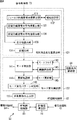
本発明の制御装置は、撮像装置により撮像される撮像画像を構成する画素の輝度値の積分値を算出する積分値算出手段と、第1の時間範囲に撮像された撮像画像について算出された積分値と、第1の時間範囲とは異なる第2の時間範囲に撮像された撮像画像について算出された積分値との変化の割合を表す積分変化量を算出する積分変化量算出手段と、安定モードまたは不安定モードに設定されるモードに対応し、積分変化量と比較されるモード変更用閾値を調整する閾値調整手段と、モードが安定モードに設定されている場合、積分変化量が安定モード用に調整されたモード変更用閾値よりも大きいときには、モードを安定モードから不安定モードに変更し、モードが不安定モードに設定されている場合、積分変化量が不安定モード用に調整されたモード変更用閾値よりも小さいときには、モードを不安定モードから安定モードに変更するモード変更手段と、モードが不安定モードから安定モードに変更されたことに対応して、駆動部を制御してフォーカス位置を制御するフォーカス位置制御処理を実行する実行手段と、フォーカス位置制御処理の実行中に撮像された複数の撮像画像毎に、撮像画像を構成する画素のうち、飽和した輝度値を有する画素の個数である飽和輝度数を算出する飽和輝度数算出手段と、複数の撮像画像における、飽和輝度数の変化の割合を表す飽和輝度数変化量を算出する飽和輝度数変化量算出手段とを備え、閾値調整手段は、モードが安定モードに設定されている場合、飽和輝度数変化量が閾値調整用閾値未満であるときには、安定モード用のモード変更用閾値を第1の値に調整し、飽和輝度数変化量が閾値調整用閾値よりも大きいときには、安定モード用のモード変更用閾値を第1の値よりも大きな第2の値に調整する。 The control device according to the present invention includes an integral value calculation unit that calculates an integral value of luminance values of pixels that constitute a captured image captured by the imaging device , and an integration that is calculated for the captured image captured in the first time range. An integral change amount calculating means for calculating an integral change amount representing a rate of change between the value and an integral value calculated for a captured image captured in a second time range different from the first time range, and a stable mode Alternatively, the threshold adjustment means for adjusting the mode change threshold to be compared with the integral change amount corresponding to the mode set to the unstable mode, and the integral change amount for the stable mode when the mode is set to the stable mode When the mode change threshold is larger than the mode change threshold, the mode is changed from the stable mode to the unstable mode, and when the mode is set to the unstable mode, the integral change amount is adjusted for the unstable mode. When the mode change threshold is smaller than the mode change threshold, the mode change means for changing the mode from the unstable mode to the stable mode, and the drive unit is controlled in response to the mode being changed from the unstable mode to the stable mode. An execution means for executing a focus position control process for controlling the focus position and a plurality of captured images captured during the execution of the focus position control process having a saturated luminance value among pixels constituting the captured image. Saturated luminance number calculating means for calculating a saturated luminance number that is the number of pixels, and saturated luminance number change amount calculating means for calculating a saturated luminance number change amount that represents a change rate of the saturated luminance number in a plurality of captured images. The threshold adjustment means includes a mode for the stable mode when the mode is set to the stable mode and the amount of change in the saturated luminance number is less than the threshold for threshold adjustment. The further use threshold is adjusted to the first value, and when the saturation luminance number change amount is larger than the threshold adjustment threshold, the mode change threshold for the stable mode is adjusted to a second value larger than the first value. .
前記飽和輝度数変化量算出手段は、複数の撮像画像毎に算出された飽和輝度数の最大値および最小値に基づいて飽和輝度数変化量を算出するようにすることができる。 The saturated luminance number change amount calculating means can calculate the saturated luminance number change amount based on the maximum value and the minimum value of the saturated luminance number calculated for each of the plurality of captured images .
本発明の制御方法は、撮像装置により撮像される撮像画像を構成する画素の輝度値の積分値を算出する積分値算出ステップと、第1の時間範囲に撮像された撮像画像について算出された積分値と、第1の時間範囲とは異なる第2の時間範囲に撮像された撮像画像について算出された積分値との変化の割合を表す積分変化量を算出する積分変化量算出ステップと、安定モードまたは不安定モードに設定されるモードに対応し、積分変化量と比較されるモード変更用閾値を調整する閾値調整ステップと、モードが安定モードに設定されている場合、積分変化量が安定モード用に調整されたモード変更用閾値よりも大きいときには、モードを安定モードから不安定モードに変更し、モードが不安定モードに設定されている場合、積分変化量が不安定モード用に調整されたモード変更用閾値よりも小さいときには、モードを不安定モードから安定モードに変更するモード変更ステップと、モードが不安定モードから安定モードに変更されたことに対応して、駆動部を制御してフォーカス位置を制御するフォーカス位置制御処理を実行する実行ステップと、フォーカス位置制御処理の実行中に撮像された複数の撮像画像毎に、撮像画像を構成する画素のうち、飽和した輝度値を有する画素の個数である飽和輝度数を算出する飽和輝度数算出ステップと、複数の撮像画像における、飽和輝度数の変化の割合を表す飽和輝度数変化量を算出する飽和輝度数変化量算出ステップとを含み、閾値調整ステップは、モードが安定モードに設定されている場合、飽和輝度数変化量が閾値調整用閾値未満であるときには、安定モード用のモード変更用閾値を第1の値に調整し、飽和輝度数変化量が閾値調整用閾値よりも大きいときには、安定モード用のモード変更用閾値を第1の値よりも大きな第2の値に調整する。 The control method of the present invention includes an integration value calculation step of calculating an integral value of luminance values of pixels constituting a captured image captured by the imaging device , and an integration calculated for the captured image captured in the first time range. An integral change amount calculating step for calculating an integral change amount representing a rate of change between the value and an integral value calculated for a captured image captured in a second time range different from the first time range; and a stable mode Or a threshold adjustment step for adjusting the mode change threshold to be compared with the integral change amount corresponding to the mode set to the unstable mode, and the integral change amount for the stable mode when the mode is set to the stable mode. If the mode change threshold is larger than the mode change threshold value, the mode is changed from the stable mode to the unstable mode, and the integral change amount is unstable when the mode is set to the unstable mode. A mode change step for changing the mode from the unstable mode to the stable mode, and when the mode is changed from the unstable mode to the stable mode. Execution step for executing a focus position control process for controlling the focus position by controlling the drive unit, and saturation among pixels constituting the captured image for each of the plurality of captured images captured during the execution of the focus position control process A saturated luminance number calculating step for calculating a saturated luminance number that is the number of pixels having the luminance value, and a saturated luminance number change for calculating a saturation luminance number change amount representing a rate of change of the saturated luminance number in a plurality of captured images. The threshold adjustment step includes a saturation luminance number change amount less than the threshold adjustment threshold when the mode is set to the stable mode. Sometimes, the mode change threshold for the stable mode is adjusted to the first value, and when the saturation luminance number change amount is larger than the threshold adjustment threshold, the mode change threshold for the stable mode is larger than the first value. Adjust to the second value.
本発明のプログラムは、撮像装置により撮像される撮像画像を構成する画素の輝度値の積分値を算出する積分値算出ステップと、第1の時間範囲に撮像された撮像画像について算出された積分値と、第1の時間範囲とは異なる第2の時間範囲に撮像された撮像画像について算出された積分値との変化の割合を表す積分変化量を算出する積分変化量算出ステップと、安定モードまたは不安定モードに設定されるモードに対応し、積分変化量と比較されるモード変更用閾値を調整する閾値調整ステップと、モードが安定モードに設定されている場合、積分変化量が安定モード用に調整されたモード変更用閾値よりも大きいときには、モードを安定モードから不安定モードに変更し、モードが不安定モードに設定されている場合、積分変化量が不安定モード用に調整されたモード変更用閾値よりも小さいときには、モードを不安定モードから安定モードに変更するモード変更ステップと、モードが不安定モードから安定モードに変更されたことに対応して、駆動部を制御してフォーカス位置を制御するフォーカス位置制御処理を実行する実行ステップと、フォーカス位置制御処理の実行中に撮像された複数の撮像画像毎に、撮像画像を構成する画素のうち、飽和した輝度値を有する画素の個数である飽和輝度数を算出する飽和輝度数算出ステップと、複数の撮像画像における、飽和輝度数の変化の割合を表す飽和輝度数変化量を算出する飽和輝度数変化量算出ステップとを含み、閾値調整ステップは、モードが安定モードに設定されている場合、飽和輝度数変化量が閾値調整用閾値未満であるときには、安定モード用のモード変更用閾値を第1の値に調整し、飽和輝度数変化量が閾値調整用閾値よりも大きいときには、安定モード用のモード変更用閾値を第1の値よりも大きな第2の値に調整する処理をコンピュータに行わせる。 The program of the present invention includes an integral value calculating step for calculating an integral value of luminance values of pixels constituting a captured image captured by the imaging device , and an integrated value calculated for the captured image captured in the first time range. And an integral change amount calculating step for calculating an integral change amount representing a rate of change from an integral value calculated for a captured image captured in a second time range different from the first time range, and a stable mode or Corresponding to the mode set to unstable mode, the threshold adjustment step for adjusting the mode change threshold to be compared with the integral change amount, and when the mode is set to stable mode, the integral change amount is for stable mode If the mode change threshold is larger than the adjusted mode change threshold value, the mode change from the stable mode to the unstable mode, and if the mode is set to the unstable mode, the integral change amount is uneasy. When the threshold value is smaller than the mode change threshold adjusted for the mode, the mode change step for changing the mode from the unstable mode to the stable mode, and driving in response to the mode being changed from the unstable mode to the stable mode An execution step of executing a focus position control process for controlling the focus position by controlling the unit and a plurality of captured images captured during the execution of the focus position control process, among pixels constituting the captured image, being saturated A saturation luminance number calculation step for calculating a saturation luminance number that is the number of pixels having luminance values, and a saturation luminance number change amount that calculates a saturation luminance number change amount representing a change rate of the saturation luminance number in a plurality of captured images. The threshold adjustment step includes a calculation step, and when the mode is set to the stable mode, the saturation luminance number change amount is less than the threshold adjustment threshold. The mode change threshold for the stable mode is adjusted to the first value, and when the saturation luminance number change amount is larger than the threshold adjustment threshold, the mode change threshold for the stable mode is set to be greater than the first value. Causes the computer to perform a process of adjusting to a large second value.
本発明の制御装置および方法、並びにプログラムにおいては、撮像装置により撮像される撮像画像を構成する画素の輝度値の積分値が算出され、第1の時間範囲に撮像された撮像画像について算出された積分値と、第1の時間範囲とは異なる第2の時間範囲に撮像された撮像画像について算出された積分値との変化の割合を表す積分変化量が算出され、安定モードまたは不安定モードに設定されるモードに対応し、積分変化量と比較されるモード変更用閾値が調整され、モードが安定モードに設定されている場合、積分変化量が安定モード用に調整されたモード変更用閾値よりも大きいときには、モードが安定モードから不安定モードに変更され、モードが不安定モードに設定されている場合、積分変化量が不安定モード用に調整されたモード変更用閾値よりも小さいときには、モードが不安定モードから安定モードに変更され、モードが不安定モードから安定モードに変更されたことに対応して、駆動部を制御してフォーカス位置を制御するフォーカス位置制御処理が実行される。そして、フォーカス位置制御処理の実行中に撮像された複数の撮像画像毎に、撮像画像を構成する画素のうち、飽和した輝度値を有する画素の個数である飽和輝度数が算出され、複数の撮像画像における、飽和輝度数の変化の割合を表す飽和輝度数変化量が算出される。また、モードが安定モードに設定されている場合、飽和輝度数変化量が閾値調整用閾値未満であるときには、安定モード用のモード変更用閾値が第1の値に調整され、飽和輝度数変化量が閾値調整用閾値よりも大きいときには、安定モード用のモード変更用閾値が第1の値よりも大きな第2の値に調整される。 In the control device, method, and program of the present invention, the integral value of the luminance values of the pixels constituting the captured image captured by the imaging device is calculated, and the calculated value is calculated for the captured image captured in the first time range. An integral change amount representing a rate of change between the integral value and the integral value calculated for the captured image captured in the second time range different from the first time range is calculated, and the stable mode or the unstable mode is set. When the mode change threshold value to be compared with the integral change amount is adjusted and the mode is set to the stable mode, the integral change amount is adjusted from the mode change threshold value adjusted for the stable mode. Is larger than the stable mode, the mode is changed from the stable mode to the unstable mode, and when the mode is set to the unstable mode, the integral change amount is adjusted to the mode for the unstable mode. When the threshold is smaller than the change threshold, the focus is controlled by controlling the driving unit in response to the mode being changed from the unstable mode to the stable mode and the mode being changed from the unstable mode to the stable mode. A position control process is executed. Then, for each of a plurality of captured images captured during the execution of the focus position control process, a saturated luminance number that is the number of pixels having a saturated luminance value among the pixels constituting the captured image is calculated. A saturation luminance number change amount representing a rate of change of the saturation luminance number in the image is calculated. Further, when the mode is set to the stable mode, when the saturation luminance number change amount is less than the threshold adjustment threshold, the mode change threshold for the stable mode is adjusted to the first value, and the saturation luminance number change amount is set. Is larger than the threshold adjustment threshold, the mode change threshold for the stable mode is adjusted to a second value larger than the first value.
本発明によれば、不必要なオートフォーカス処理を容易に低減させることができる。 According to the present invention, unnecessary autofocus processing can be easily reduced.
以下に本発明の実施の形態を説明するが、本明細書に記載の発明と、発明の実施の形態との対応関係を例示すると、次のようになる。この記載は、請求項に記載されている発明をサポートする実施の形態が本明細書に記載されていることを確認するためのものである。従って、発明の実施の形態中には記載されているが、発明に対応するものとして、ここには記載されていない実施の形態があったとしても、そのことは、その実施の形態が、その発明に対応するものではないことを意味するものではない。逆に、実施の形態が発明に対応するものとしてここに記載されていたとしても、そのことは、その実施の形態が、その発明以外の発明には対応しないものであることを意味するものでもない。 Embodiments of the present invention will be described below. The correspondence relationship between the invention described in this specification and the embodiments of the invention is exemplified as follows. This description is intended to assure that embodiments supporting the claimed invention are described in this specification. Therefore, although there is an embodiment which is described in the embodiment of the invention but is not described here as corresponding to the invention, it means that the embodiment is not It does not mean that it does not correspond to the invention. Conversely, even if an embodiment is described herein as corresponding to an invention, that means that the embodiment does not correspond to an invention other than the invention. Absent.
さらに、この記載は、本明細書に記載されている発明の全てを意味するものではない。換言すれば、この記載は、本明細書に記載されている発明であって、この出願では請求されていない発明の存在、すなわち、将来、分割出願されたり、補正により追加されたりする発明の存在を否定するものではない。 Further, this description does not mean all the inventions described in this specification. In other words, this description is an invention described in the present specification and is not claimed in this application, that is, an invention that will be filed in the future or added by amendment. Is not to deny.
本発明においては、撮像装置(例えば、図3の撮像装置50)の光学素子(例えば、図3のフォーカスレンズ61やウォブリングレンズ62)を駆動させて被写体を撮像する際のフォーカス位置を調整する駆動部(例えば、図3のAF駆動部51)の制御に関する処理を実行する制御装置(例えば、図3のAF制御部53)が提供される。この制御装置では、撮像装置により撮像される撮像画像を構成する画素の輝度値の積分値を算出する積分値算出手段(例えば、図4のフィールド内輝度積分値算出部131)と、第1の時間範囲に撮像された撮像画像について算出された積分値と、第1の時間範囲とは異なる第2の時間範囲に撮像された撮像画像について算出された積分値との変化の割合を表す積分変化量を算出する積分変化量算出手段(例えば、図4の区間別輝度積分平均値算出部133乃至正規化部136)と、安定モードまたは不安定モードに設定されるモードに対応し、積分変化量と比較されるモード変更用閾値を調整する閾値調整手段(例えば、図4の起動条件調整部84)と、モードが安定モードに設定されている場合、積分変化量が安定モード用に調整されたモード変更用閾値よりも大きいときには、モードを安定モードから不安定モードに変更し、モードが不安定モードに設定されている場合、積分変化量が不安定モード用に調整されたモード変更用閾値よりも小さいときには、モードを不安定モードから安定モードに変更するモード変更手段(例えば、モード更新部145)と、モードが不安定モードから安定モードに変更されたことに対応して、駆動部を制御してフォーカス位置を制御するフォーカス位置制御処理を実行する実行手段(例えば、図3のAF制御処理部83)と、フォーカス位置制御処理の実行中に撮像された複数の撮像画像毎に、撮像画像を構成する画素のうち、飽和した輝度値を有する画素の個数である飽和輝度数を算出する飽和輝度数算出手段(例えば、図5の飽和輝度数算出部151)と、複数の撮像画像における、飽和輝度数の変化の割合を表す飽和輝度数変化量を算出する飽和輝度数変化量算出手段(例えば、図5の閾値選択部155)とを備え、閾値調整手段(例えば、図5の閾値更新部156)は、モードが安定モードに設定されている場合、飽和輝度数変化量が閾値調整用閾値未満であるときには、安定モード用のモード変更用閾値を第1の値に調整し、飽和輝度数変化量が閾値調整用閾値よりも大きいときには、安定モード用のモード変更用閾値を第1の値よりも大きな第2の値に調整する。
In the present invention, an optical element (for example, the
本発明においては、撮像装置(例えば、図3の撮像装置50)の光学素子(例えば、図3のフォーカスレンズ61やウォブリングレンズ62)を駆動させて被写体を撮像する際のフォーカス位置を調整する駆動部(例えば、図3のAF駆動部51)の制御に関する処理を実行する制御装置(例えば、図3のAF制御部53)の制御方法が提供される。この制御方法においては、撮像装置により撮像される撮像画像を構成する画素の輝度値の積分値を算出する積分値算出ステップ(例えば、図14のステップS21)と、第1の時間範囲に撮像された撮像画像について算出された積分値と、第1の時間範囲とは異なる第2の時間範囲に撮像された撮像画像について算出された積分値との変化の割合を表す積分変化量を算出する積分変化量算出ステップ(例えば、図14のステップS22乃至ステップS24)と、安定モードまたは不安定モードに設定されるモードに対応し、積分変化量と比較されるモード変更用閾値を調整する閾値調整ステップと、モードが安定モードに設定されている場合、積分変化量が安定モード用に調整されたモード変更用閾値よりも大きいときには、モードを安定モードから不安定モードに変更し、モードが不安定モードに設定されている場合、積分変化量が不安定モード用に調整されたモード変更用閾値よりも小さいときには、モードを不安定モードから安定モードに変更するモード変更ステップ(例えば、図15のステップS44)と、モードが不安定モードから安定モードに変更されたことに対応して、駆動部を制御してフォーカス位置を制御するフォーカス位置制御処理を実行する実行ステップ(例えば、図13のステップS4)と、フォーカス位置制御処理の実行中に撮像された複数の撮像画像毎に、撮像画像を構成する画素のうち、飽和した輝度値を有する画素の個数である飽和輝度数を算出する飽和輝度数算出ステップ(例えば、図17のステップS81)と、複数の撮像画像における、飽和輝度数の変化の割合を表す飽和輝度数変化量を算出する飽和輝度数変化量算出ステップ(例えば、図17のステップS85)とを含み、閾値調整ステップ(例えば、図17のステップS86乃至ステップS89)は、モードが安定モードに設定されている場合、飽和輝度数変化量が閾値調整用閾値未満であるときには、安定モード用のモード変更用閾値を第1の値に調整し、飽和輝度数変化量が閾値調整用閾値よりも大きいときには、安定モード用のモード変更用閾値を第1の値よりも大きな第2の値に調整する。
In the present invention, an optical element (for example, the
本発明のプログラムにおいても、各ステップが対応する実施の形態(但し一例)は、本発明の制御方法と同様である。 Also in the program of the present invention, the embodiment (however, an example) corresponding to each step is the same as the control method of the present invention.
以下、本発明の実施の形態について図を参照して説明する。 Hereinafter, embodiments of the present invention will be described with reference to the drawings.
図3は、本発明を適用した撮像装置の一実施形態に係る構成例を示す図である。 FIG. 3 is a diagram illustrating a configuration example according to an embodiment of an imaging apparatus to which the present invention is applied.
図3において、撮像装置50は、AF(Auto Focus)駆動部51、画像処理部52、およびAF制御部53を有しており、被写体を撮像し、動画または静止画の画像データを得る装置である。撮像装置50は、得られた画像データを記録媒体に記録したり、外部に出力したりする。なお、図3においては、撮像装置50の構成の内、本発明に関わる部分のみを示している。
In FIG. 3, an imaging device 50 has an AF (Auto Focus)
AF駆動部51は、フォーカスレンズ61、ウォブリングレンズ62、レンズ駆動部63、駆動制御部64、センサ65、およびスイッチ(SW)66を有しており、AF制御部53の制御に基づいて、光学系を駆動させ、画像処理部52に取り込まれる光のフォーカス位置調整処理を行う。
The
フォーカスレンズ61は、画像処理部52に入射する光の光軸方向に駆動し、その光のフォーカス位置(得られる撮影画像のフォーカス位置)を制御する。ウォブリングレンズ62は、画像処理部52に入射する光の光軸方向に微小に振動(ウォブリング)し、撮影画像のフォーカス位置を微小にずらす。このウォブリングレンズ62は、焦点調整処理(フォーカス処理)中におけるフォーカスレンズ61の動かす向きを決定するのに利用される。なお、このフォーカスレンズ61とウォブリングレンズ62は、1組のレンズにより実現する(フォーカスレンズ61をウォブリングレンズ62としてウォブリング動作させる)ようにしてもよい。
The
レンズ駆動部63は、駆動制御部64より供給される制御情報に基づいて、フォーカスレンズ61およびウォブリングレンズ62の位置や動作を制御することによりフォーカス位置を制御する(フォーカス位置を制御するための動作を行わせる)。駆動制御部64は、後述するようにAF制御部53のAF制御処理部83とシリアルバスで接続されており、AF制御処理部83より供給されるフォーカス制御指令やウォブリング制御指令等の制御情報に基づいて、レンズ駆動部63にフォーカスレンズ61およびウォブリングレンズ62の駆動に関する制御情報を供給する。例えば、駆動制御部64は、レンズ駆動部63に対して、制御情報を供給し、フォーカスレンズ61の位置を移動するように指示したり、ウォブリングレンズ62のウォブリング動作を開始させたりする。
The
また、駆動制御部64は、センサ65より供給されるアイリス値やフォーカス位置に関する情報を、シリアルバスを介して、AF制御処理部83に供給する。さらに、駆動制御部64は、スイッチ(SW)66の状態に応じて動作が制御される。例えば、スイッチ66がオン状態の場合のみ駆動制御部64は、上述した制御処理や通信処理を行い、スイッチ66がオフ状態の場合、駆動制御部64は、休止状態となり各処理を実行しない。
Further, the
センサ65は、フォーカス位置、ズーム位置(焦点距離)、およびアイリス値等を測定するセンサであり、測定したそれらの情報を、駆動制御部64を介してAF制御処理部83に供給する。スイッチ(SW)66は、AF処理を行うか否かをユーザが制御するためのスイッチであり、その状態を駆動制御部64に通知する。
The
画像処理部52は、撮像装置50に入射される光から電気信号の画像信号を生成する処理部であり、CCD(Charge Coupled Devices)71、増幅部72、および信号処理部73を有している。
The image processing unit 52 is a processing unit that generates an image signal of an electrical signal from light incident on the imaging device 50, and includes a CCD (Charge Coupled Devices) 71, an
CCD71は、フォトダイオード等の光電変換素子を有するCCDを利用した撮像素子であり、フォーカスレンズ61およびウォブリングレンズ62を介して入射される入射光を光電変換し、入射光量に対応する電荷を蓄積すると、それを吐き出すことにより電気信号の画像信号を得る。CCD71は、その画像信号を増幅部72に供給する。増幅部72は、CDS回路(Correlated Double Sampling circuit)、AGC回路(Automatic Gain Control circuit)、およびA/D(Analog / Digital)変換回路等を含み、CCD71より供給される画像信号のリセットノイズを除去したり、画像信号を増幅したり、アナログ信号の画像信号をデジタル信号に変換したりした後、そのデジタルの画像信号を信号処理部73に供給する。
The
信号処理部73は、供給された画像信号に対してAE(Auto Exposure)処理やAWB(Auto White Balance)処理や、γ補正等の画像処理等を施した後、その画像信号を後段に出力するとともに、AF制御部53の評価値算出部81、AF起動制御部82、および起動条件調整部84に供給する。また、信号処理部73は、画像信号の水平同期信号や垂直同期信号、並びにシステムクロック信号等の制御用同期信号を、評価値算出部81、AF起動制御部82、および起動条件調整部84に供給する。
The
AF制御部53は、画像処理部52より供給される画像信号等に基づいて、AF駆動部51を制御し、AF処理の制御に関する処理を行う。AF制御部53は、評価値算出部81、AF起動制御部82、AF制御処理部83、および起動条件調整部84を有している。
The
評価値算出部81は、画像処理部52の信号処理部73より供給される画像信号や同期信号、並びにAF制御処理部83より供給される設定データ等に基づいて、取り込み画像(画像信号)の「ぼけ」具合を評価する評価値を算出する。評価値算出部81は、算出した評価値をAF制御処理部83に供給する。
The evaluation
AF起動制御部82は、信号処理部73より供給される画像信号や同期信号に基づいて、AF処理の起動に関する制御処理を行い、その制御結果をAF制御処理部83に供給する。AF制御処理部83は、AF起動制御部82の制御に基づいて、AF処理を開始し、評価値算出部81より供給される評価値に基づいて、AF処理を実行し、シリアルバスを介して制御情報を駆動制御部64に供給する。また、AF制御処理部83は、評価値の算出に関する設定データを生成し、その設定データを評価値算出部81に供給する。さらに、AF制御処理部83は、シリアルバスを介して、駆動制御部64よりフォーカス位置やアイリス値等のセンサ情報を取得する。また、AF制御処理部83は、AF処理の制御を行う際に、最初に、起動条件調整部84にAFの起動条件の調整処理を実行させる。
The AF
起動条件調整部84は、AF制御処理部83より供給される起動条件調整処理の開始指示を取得すると、信号処理部73より供給される画像信号や同期信号に基づいて、AF起動制御部82によるAF起動制御に用いられるAF処理の起動条件を調整する処理を行う。そして、起動条件調整部84は、その調整された起動条件をAF起動制御部82に供給し、AF起動制御において使用させる。
When the activation
また、AF制御部53は、バス90、ROM(Read Only Memory)91、入力部92、出力部93、記憶部94、通信部95、およびドライブ96をさらに有している。起動条件調整部84には、バス90が接続され、そのバス90を介して、ROM91乃至ドライブ96が接続される。
The
ROM91は、読み出し専用の記憶媒体を有しており、起動条件調整部84において実行されるプログラムやデータが予め記憶されている。ROM91に記憶されているプログラムやデータは、起動条件調整部84により、バス90を介して必要に応じて読み出される。入力部92は、スイッチやボタン等の入力デバイスを有しており、例えばユーザにより入力された指示情報等を受け付け、それらを、バス90を介して起動条件調整部84に供給する。出力部93は、LED(Light Emitting Diode)ディスプレイ、LCD(Liquid Crystal Display)、または有機EL(Electro Luminescence)ディスプレイ等よりなる表示部や、スピーカ等よりなる音声出力部を有しており、起動条件調整部84よりバス90を介して供給された情報を表示したり出力したりする。
The
記憶部94は、ハードディスクや半導体メモリ等を有し、起動条件調整部84により実行されるプログラムやデータが記憶されたり、起動条件調整部84より供給されるデータ等を記憶したりする。通信部95は、例えば、モデム、LAN(Local Area Network)アダプタ、USB(Universal Serial Bus)インタフェース、IEEE(Institute of Electrical and Electronic Engineers)1394インタフェース、SCSI(Small Computer System Interface)、またはIEEE802.11xアダプタ等を有し、所定の通信規格に基づいたインタフェース処理を行い、ネットワークを介して他の装置と通信を行い、例えば、他の装置より情報を受信し、それを起動条件調整部84に供給したり、起動条件調整部84からの情報を他の装置に送信したりする。
The storage unit 94 includes a hard disk, a semiconductor memory, and the like, and stores programs and data executed by the activation
ドライブ96は、磁気ディスク、光ディスク、光磁気ディスク、或いは半導体メモリなどのリムーバブルメディア97が適宜装着される読み出し書き込み処理部である。ドライブ96は、例えば、装着されたリムーバブルメディア97からプログラムやデータを読み出し、それを、必要に応じて記憶部94にインストールさせたり、起動条件調整部84に供給したりする。また、ドライブ96は、例えば、バス90を介して起動条件調整部84より取得したプログラムやデータを、装着されているリムーバブルメディア97に記録する。
The
起動条件調整部84が実行する処理をソフトウエアにより実行させる場合には、そのソフトウエアを構成するプログラムが、ネットワークや記録媒体からインストールされる。
When the processing executed by the activation
この記録媒体は、例えば、装置本体とは別に、ユーザにプログラムを配信するために配布される、プログラムが記録されている磁気ディスク(フレキシブルディスクを含む)、光ディスク(CD-ROM(Compact Disk-Read Only Memory),DVD(Digital Versatile Disk)を含む)、光磁気ディスク(MD(Mini-Disk)(登録商標)を含む)、もしくは半導体メモリなどよりなるリムーバブルメディア97により構成されるだけでなく、装置本体に予め組み込まれた状態でユーザに配信される、プログラムが記録されているROM91や、記憶部94に含まれるハードディスクや半導体メモリ等で構成される。
This recording medium is, for example, a magnetic disk (including a flexible disk) on which a program is recorded, an optical disk (CD-ROM (Compact Disk-Read), which is distributed to distribute the program to the user separately from the apparatus main body. The apparatus is not only constituted by a removable medium 97 composed of only memory), DVD (Digital Versatile Disk), magneto-optical disk (including MD (Mini-Disk) (registered trademark)), or semiconductor memory, etc. The program is composed of a
次に、動作について説明する。 Next, the operation will be described.
撮影が開始されると、画像処理部52のCCD71は、点線矢印101に示されるような光軸でAF駆動部51のフォーカスレンズ61およびウォブリングレンズ62を介して入射された光を光電変換し、電気信号の画像情報(画像信号)を得る。そしてCCD71は、矢印102のように、その画像信号を増幅部72に供給する。増幅部72は、その画像信号を所定の方法で増幅させると、その増幅済みの画像信号を矢印103のように信号処理部73に供給する。信号処理部73は、供給された画像信号に対して画像処理を施すなどした後、それを、矢印104Aに示されるように図示せぬ後段に出力するとともに、矢印104B乃至矢印104Dに示されるようにAF制御部53の評価値算出部81、AF起動制御部82、および起動条件調整部84に供給する。また、信号処理部73は、矢印105A乃至矢印105Cに示されるように、同期信号を評価値算出部81、AF起動制御部82、および起動条件調整部84に供給する。
When shooting is started, the
AF起動制御部82は、信号処理部73より供給される画像信号(取り込み画像の内容)に基づいてAF処理(ワンショットAF処理)の起動に関する制御処理を行う。詳細については後述するが、AF起動制御部82は画像信号の輝度値に基づいて、AF処理を行うか否かを判定し、起動条件調整部84に調整される所定の条件が満たされる場合、矢印107のようにAF制御処理部83に対してAF処理の起動を指示する。
The AF
AF処理の起動が指示されると、AF制御処理部83は、両矢印106のように評価値算出部81と連携してAF処理の制御に関する処理を行う。つまり、評価値算出部81は、AF制御処理部83より供給される設定データ等に基づいて、信号処理部73より供給される画像信号に対応する取り込み画像の「ぼけ」具合を評価する評価値を所定の算出方法で算出する。例えば、評価値は、フレーム画像の一部の画像領域内(評価枠内)におけるコントラストの大きさを示す値であり、その評価枠内の高周波成分の合計値等に基づいて算出される。評価値算出部81は、このような評価値を算出すると、それをAF制御処理部83に供給する。
When the activation of the AF process is instructed, the AF
AF制御処理部83は、その供給された評価値と、矢印110Bのようにシリアルバスを介して駆動制御部64より供給されたフォーカス位置やアイリス値等のセンサ情報に基づいて、例えばウォブリング動作や、山登り判定による最適なフォーカス位置検索等のAF処理の具体的な動作を制御する。このような制御情報は、矢印110Aのようにシリアルバスを介して駆動制御部64に供給される。また、AF制御処理部83は、AF制御処理を開始すると、その開始したという情報を、矢印108のように起動条件調整部84に供給する。
The AF
AF制御処理部83よりAF制御処理の開始が通知されると、起動条件調整部84は、AF処理の起動条件(閾値)を設定し、矢印109に示されるように、その起動条件(閾値)の情報をAF制御処理部83に供給し、セットさせる。
When the start of the AF control process is notified from the AF
駆動制御部64は、センサ65より矢印111のようにフォーカス位置やアイリス値等のセンサ情報を取得し、シリアルバスを介して、そのセンサ情報を、矢印110BのようにAF制御処理部83に供給する。また、駆動制御部64は、SW66より矢印112のようにAF処理の設定に関するユーザ指示を受け付け、その指示に基づいて、矢印110Aのようにシリアルバスを介してAF制御処理83より供給される制御情報を受け付け、その制御情報に基づいた処理を行い、矢印113のように、レンズ位置等を指示するレンズ駆動制御情報をレンズ駆動部63に供給する。レンズ駆動部63は、そのレンズ駆動制御情報に基づいて、矢印114のようにフォーカスレンズ61を駆動させたり、矢印115のようにウォブリングレンズ62を駆動させたりする。
The
撮像装置50においては、このようにAF処理が制御される。 In the imaging apparatus 50, the AF process is controlled in this way.
図4は、AF制御部53のAF起動制御部82の詳細な構成例を示すブロック図である。
FIG. 4 is a block diagram illustrating a detailed configuration example of the AF
図4において、AF起動制御部82は、相対角度変化量算出部121、モード変化検出部122、およびAF起動指示出力部123を有している。
In FIG. 4, the AF
相対角度変化量算出部121は、被写体と撮像装置50の相対角度(被写体と撮影方向の相対関係)が1区間(単位時間)当たりにどれくらい変化したかという変化量(相対角度変化量p0)を求める処理部であり、フィールド内輝度積分値算出部131、領域設定部132、区間別輝度積分平均値算出部133、区間別輝度積分平均値保持部134、差分値算出部135、および正規化部136を有している。
The relative angle change amount calculation unit 121 calculates a change amount (relative angle change amount p0) indicating how much the relative angle between the subject and the imaging device 50 (relative relationship between the subject and the shooting direction) changes per section (unit time). This is a processing unit to be calculated, the in-field luminance integral
フィールド内輝度積分値算出部131は、フィールド画像(プログレッシブ画像であればフレーム画像)毎に、各画素の輝度値(y)を積分(合計)し、輝度積分値(フィールド内輝度積分値ynow_w5_f0)を算出する。そのとき、フィールド内輝度積分値算出部131は、フィールド画像の、領域設定部132において設定される領域内の画素の輝度積分値をフィールド内輝度積分値として算出する。フィールド内輝度積分値算出部131は、算出したフィールド内輝度積分値ynow_w5_f0を区間別輝度積分平均値算出部133に供給する。
The in-field luminance integral
領域設定部132は、フィールド内輝度積分値算出部131がフィールド内輝度積分値ynow_w5_f0を算出する領域を設定する。つまり、フィールド内輝度積分値ynow_w5_f0は、撮影画枠の全体または一部よりなる予め定められた範囲の画素の輝度値の合計値(積分値)である。
The
区間別輝度積分平均値算出部133は、フィールド内輝度積分値算出部131より供給されるフィールド単位の輝度積分値であるフィールド内輝度積分値ynow_w5_f0について、所定の時間(区間)単位(例えば、Nフィールド毎(Nは自然数))でその平均値(区間別輝度積分平均値yadd_w5_f0)を算出し、その区間別輝度積分平均値(算出途中の値を含む)を区間別輝度積分平均値保持部134に供給し、保持させる。1区間の平均値yadd_w5_f0を算出すると、区間別輝度積分平均値算出部133は、その値yadd_w5_f0を区間別輝度積分平均値保持部134に供給し、保持させるとともに差分値算出部135にも供給する。
The by-section luminance integral average value calculation unit 133 uses the predetermined time (section) unit (for example, N) for the in-field luminance integration value ynow_w5_f0 that is the luminance integration value of the field unit supplied from the in-field luminance integration
なお、区間別輝度積分平均値yadd_w5_f0は、最新の区間(Nフィールド分)のフィールド内輝度積分値ynow_w5_f0の平均値である。つまり、区間別輝度積分平均値yadd_w5_f0は、現在のフィールドからNフィールド前のフィールドまでの各フィールドに対応するフィールド内輝度積分値ynow_w5_f0の平均値である。なお、1区間前の区間別輝度積分平均値yadd_w5_f1は、N+1フィールド前のフィールドから2Nフィールド前のフィールド前の各フィールドに対応するフィールド内輝度積分値ynow_w5_f0の平均値である。 The section-by-section luminance integral average value yadd_w5_f0 is an average value of the in-field luminance integral values ynow_w5_f0 in the latest section (for N fields). In other words, the luminance integrated average value yadd_w5_f0 for each section is an average value of the in-field luminance integrated values ynow_w5_f0 corresponding to each field from the current field to the field N fields before. The luminance integrated average value yadd_w5_f1 for each previous section is an average value of the in-field integrated luminance value ynow_w5_f0 corresponding to each field 2N fields before the field before the N + 1 field.
従って、区間別輝度積分平均値保持部134は、最新の区間別輝度積分平均値yadd_w5_f0が算出されると(1区間分の平均値の算出が終了すると)、それまで保持していた1区間前の区間別輝度積分平均値yadd_w5_f1を削除し、それまで保持していた区間別輝度積分平均値yadd_w5_f0を、1区間前の区間別輝度積分平均値yadd_w5_f1に変更し、最新の区間別輝度積分平均値yadd_w5_f0を保持する。なお、区間別輝度積分平均値保持部134に保持されているフィールド内輝度積分値ynow_w5_f0と、算出途中の区間別輝度積分平均値yadd_w5_f0は、フィールド単位で更新される。 Accordingly, when the latest luminance integrated average value by section yadd_w5_f0 is calculated (when the calculation of the average value for one section is completed), the section-by-section luminance integrated average value holding unit 134 The luminance integration average value yadd_w5_f1 for each section is deleted, and the luminance integration average value yadd_w5_f0 for each section that has been held until then is changed to the luminance integration average value yadd_w5_f1 for the previous section. Holds yadd_w5_f0. The in-field luminance integrated value ynow_w5_f0 held in the section-specific luminance integral average value holding unit 134 and the section-by-section luminance integrated average value yadd_w5_f0 being updated are updated in units of fields.
差分値算出部135は、このように算出された最新の区間別輝度積分平均値yadd_w5_f0と、区間別輝度積分平均値保持部134より取得した以前(1つ前の区間)の区間別輝度積分平均値yadd_w5_f1との差分値(yadd_w5_f0−yadd_w5_f1)を算出し、その算出結果と、最新のフィールド内輝度積分値ynow_w5_f0を正規化部136に供給する。
The difference value calculating unit 135 calculates the latest luminance integrated average value by section yadd_w5_f0 calculated in this way and the luminance integrated average by section before (one previous section) obtained from the luminance integrated average value holding unit by section 134. A difference value (yadd_w5_f0−yadd_w5_f1) from the value yadd_w5_f1 is calculated, and the calculation result and the latest in-field luminance integrated value ynow_w5_f0 are supplied to the
正規化部136は、差分値算出部135より供給された差分値を、最新のフィールド内輝度積分値ynow_w5_f0と1区間のフィールド数Nで正規化し、その正規化された値、すなわち、輝度積分値の変化の割合を、相対角度変化量(p0)として、モード変化検出部122のモード判別部141に供給する。
The
つまり、相対角度変化量p0は、以下の式(1)により求めることができる。 That is, the relative angle change amount p0 can be obtained by the following equation (1).

モード変化検出部122は、相対角度変化量算出部121において算出された相対角度変化量(p0)に基づいて、撮影画像の内容の変化の様子、つまり変化のモードが変化したか否か(モード変化)を検出する処理部であり、モード判別部141、モードフラグ142、閾値保持部143、更新確認部144、モード更新部145、およびモード変化パターン判定部146を有している。
Based on the relative angle change amount (p0) calculated by the relative angle change amount calculation unit 121, the mode change detection unit 122 determines whether the content of the captured image has changed, that is, whether the change mode has changed (mode). Change) and a mode determination unit 141, a
モード判別部141は、相対角度変化量算出部121の正規化部136より供給される相対角度変化量に基づいて、現在のモードを判定する。ここでモードとは、撮影画像の内容の変化の様子をその程度によって状態として分けたものである。ここでは安定モードと不安定モードの2つのモードが存在する。要するに、モード判別部141は、相対角度変化量(p0)が大きいか小さいかによって、被写体が撮影装置50の撮影角度に対して大きく動いている(不安定モードである)か否(安定モードである)かを判別する。モード判別部141は、モードフラグ142を参照し、1つ前の区間のモードを特定すると、閾値保持部143よりそのモードに対応する閾値を取得する。そしてモード判別部141は、その閾値を用いて、撮影角度変化量から現在の区間のモードを判別する。モード判別部141は、そのモードの判別結果と、モードフラグ142より読み出した1つ前の区間のモードとを更新確認部144に供給する。
The mode determination unit 141 determines the current mode based on the relative angle change amount supplied from the
モードフラグ142は、モード判別部141により判別されたモードが設定される。すなわち、モードフラグ142には、安定モードであるか不安定モードであるかを示す情報(フラグ)がセットされる。閾値保持部143は、モード判別部141がモードを判別する際に用いる閾値(モード毎に設定される閾値αとβ)を保持する。なお、この閾値保持部143に保持される閾値は、起動条件調整部84により設定された値である。
The
更新確認部144は、モード判別部141より供給される情報に基づいてモードが更新されたか否かを判定し、その判定結果と、モード判別部141において判別された現在の区間のモードの情報を、モード更新部145およびモード変化パターン判別部146に供給する。
The update confirmation unit 144 determines whether or not the mode has been updated based on the information supplied from the mode determination unit 141, and determines the determination result and the mode information of the current section determined by the mode determination unit 141. , To the
モード更新部145は、更新確認部144よりモードが更新されたと通知されると、モードフラグ142の値を更新し、新たなモードを示す値をセットする。例えば、モードフラグ142に安定モードを示す値がセットされている場合、モード更新部145は、その値を「不安定モードを示す値」に更新する。また、例えば、モードフラグ142に不安定モードを示す値がセットされている場合、モード更新部145は、その値を「安定モードを示す値」に更新する。
When notified from the update confirmation unit 144 that the mode has been updated, the
モード変化パターン判定部146は、更新確認部144において確認された更新がどのような更新であったか、すなわちモード変化のパターンを判定する。つまり、モード変化パターン判定部146は、モードが安定モードから不安定モードに移行したのか、不安定モードから安定モードに移行したのかを判定し、その判定結果をAF起動指示出力部123に供給する。
The mode change
AF起動指示出力部123は、モード変化検出部122のモード変化パターン判定部146の判定結果に基づいて、AF起動指示をAF制御処理部83に対して出力する。つまり、AF起動指示出力部123は、モード変化パターン判定部146が、モードが不安定モードから安定モードに移行したと判定した場合のみ、AF処理を開始させる制御情報であるAF起動指示をAF制御処理部83に供給する。
The AF activation instruction output unit 123 outputs an AF activation instruction to the AF
以上のように、AF起動制御部82においては、相対角度変化量算出部121がAF処理の起動を制御するパラメータとして、カメラと被写体の相対角度の変化量を算出し、モード変化検出部122が、その変化量のモード変化パターンを特定し、AF起動指示出力部123がそのモード変化パターンに基づいて、AF制御処理部83にAF処理の起動指示を出力する。
As described above, in the AF
図5は、図3のAF制御部53の起動条件調整部84の詳細な構成例を示すブロック図である。
FIG. 5 is a block diagram illustrating a detailed configuration example of the activation
図5において、起動条件調整部84は、AF起動制御部82の閾値保持部143に保持されるモード判別用の閾値の値を撮影状況(撮影画像内容)に応じて制御(調整)する処理部である。
In FIG. 5, the activation
一般的に、フォトダイオード等の光電変換素子は、正常に量子化可能な輝度レベルに限界があり、例えば、被写体の光量が強すぎる場合、その撮影画像の輝度値は飽和し、所謂「白飛び」してしまう。より具体的に説明すると、例えば、被写体に照明等の光量の多い物体が含まれるような場合、撮影画像のその部分の画素の輝度値が飽和する恐れがある。そのような場合、仮に、実際の照明(被写体)では場所(部分)によって明暗があったとしても、撮影画像においては、その明るい部分も暗い部分も輝度値が量子化レベルの上限に達してしまい、いずれも「真白」として表現され、明暗の区別ができない(所謂「白飛び」)。 In general, a photoelectric conversion element such as a photodiode has a limit on a luminance level that can be normally quantized. For example, when the amount of light of a subject is too strong, the luminance value of the photographed image is saturated, so-called “whiteout” "Resulting in. More specifically, for example, when the subject includes an object with a large amount of light such as illumination, the luminance value of the pixel in that portion of the captured image may be saturated. In such a case, even if the actual illumination (subject) is bright or dark depending on the location (part), the brightness value of the photographed image reaches the upper limit of the quantization level in both the bright and dark parts. These are expressed as “pure white” and cannot be distinguished from light and dark (so-called “white skip”).
詳細については後述するが、このような輝度値が飽和した画素を含む撮影画像の場合、その画像の内容によっては、AF処理等により発生するフォーカス位置の変化によって、撮影画像のフィールド内輝度積分値が大幅に変化し、AF処理を不要に起動させてしまう恐れがある。そこで、起動条件調整部84は、撮影画像の内容によって(撮影画像に含まれる飽和輝度に基づいて)起動条件を調整する。
Although details will be described later, in the case of a photographed image including pixels with saturated luminance values, depending on the content of the image, the in-field integrated luminance value of the photographed image due to a change in focus position caused by AF processing or the like. May change drastically and activate AF processing unnecessarily. Therefore, the activation
そのような処理を行うため、起動条件調整部84は、飽和輝度数算出部151、飽和輝度数履歴保持部152、飽和輝度数最大値検索部153、飽和輝度数最小値検索部154、閾値選択部155、および閾値更新部156を有している。
In order to perform such processing, the activation
飽和輝度数算出部151は、AF制御処理部83よりAF処理開始を指示されると、信号処理部73より供給される画像信号と同期信号に基づいて、各画素の輝度値を参照することにより、フィールド(プログレッシブ画像であればフレーム)内に含まれる輝度値が飽和した画素の数である飽和輝度数を算出する。つまり、飽和輝度数算出部151は、AF処理におけるウォブリング動作中の撮影画像について、各フィールドの飽和輝度数を算出する。
When the AF
飽和輝度数算出部151は、飽和輝度数を算出すると、順次、それを飽和輝度数履歴保持部152に供給し、保持させる。飽和輝度数算出部151は、このようにMフィールド分(Mは予め定められた任意の自然数)の飽和輝度数を算出すると、飽和輝度数の算出処理を終了し、そのことを飽和輝度数最大値検索部153に通知する。
When the saturated luminance number calculating unit 151 calculates the saturated luminance number, the saturated luminance number calculating unit 151 sequentially supplies the saturated luminance number to the saturated luminance number
飽和輝度数履歴保持部152は、RAM等の半導体メモリやハードディスク等に代表される記憶素子(記録媒体)により構成され、それによって所定のサイズの記憶領域を有している。飽和輝度数履歴保持部152は、その記憶領域に、飽和輝度数算出部151より供給される飽和輝度数を、最大Mフィールド分、履歴として保持する。
The saturated luminance number
例えば、図5において、飽和輝度数履歴保持部152は、最新のフィールド画像の飽和輝度数である現フィールド飽和輝度数161−1、現フィールドより1つ前のフィールド画像の飽和輝度数である1前フィールド飽和輝度数161−2、現フィールドより2つ前のフィールド画像の飽和輝度数である2前フィールド飽和輝度数161−3、・・・、現フィールドより(M−1)前のフィールド画像の飽和輝度数である(M−1)前フィールド飽和輝度数161−M(つまり、最新のMフィールド分の飽和輝度数)を、履歴として保持している。
For example, in FIG. 5, the saturation luminance number
飽和輝度数履歴保持部152は、供給された最新の飽和輝度数を、Mフィールド分保持するまで、順次保持していく。そして、飽和輝度数履歴保持部152は、飽和輝度数をMフィールド分保持した後は、最新の飽和輝度数が供給される度に、保持している中で最も古い履歴((M−1)前フィールド飽和輝度数161−M)を削除し、供給された最新の(フィールドの)飽和輝度数を履歴として保持する(保持する飽和輝度数の履歴を更新する)。
The saturated luminance number
飽和輝度数最大値検索部153は、飽和輝度数算出部151より算出処理の終了を通知されると、飽和輝度数履歴保持部152に保持されている飽和輝度数の履歴を参照し、その中から飽和輝度数が最大値の履歴を検索し、その最大値の情報を取得する。飽和輝度数最大値検索部153は、その最大値の情報を閾値選択部155に供給し、その最大値検索処理の終了を飽和輝度数最小値検索部154に通知する。
When the saturation luminance number maximum
飽和輝度数最小値検索部154は、飽和輝度数最大値検索部153より最大値検索処理の終了を通知されると、飽和輝度数履歴保持部152に保持されている飽和輝度数の履歴を参照し、その中から飽和輝度数が最小値の履歴を検索し、その最小値の情報を取得する。飽和輝度数最小値検索部154は、その最小値の情報を閾値選択部155に供給するとともに、その最小値検索処理の終了を通知する。
When the saturation brightness number minimum
閾値選択部155は、飽和輝度数最小値検索部154より最小値検索処理の終了を通知されると、飽和輝度数最大値検索部153より供給された飽和輝度数の最大値(最新のMフィールド分における飽和輝度数の最大値)と、飽和輝度数最小値検索部154より供給された飽和輝度数の最小値(最新のMフィールド分における飽和輝度数の最小値)に基づいて、相対角度変化量のモード判別に用いられる閾値(閾値保持部143に保持される閾値)を選択する処理を行う。具体的には、閾値選択部155は、以下の式(2)で表される判別式を用いて、ウォブリング中の飽和輝度数の変動の様子を判別し、その判別結果(ウォブリング中の飽和輝度数の変動の様子)に応じて最適な閾値を選択する。
When the
(最新のMフィールド分における飽和輝度数の最大値)/{(最新のMフィールド分における飽和輝度数の最小値)+1}>γ ・・・(2) (Maximum value of saturation luminance number in latest M field) / {(Minimum value of saturation luminance number in latest M field) +1}> γ (2)
式(2)において、γは任意の定数である。また、式(2)の分母において、最新のMフィールド分における飽和輝度数の最小値に値「1」を加算しているのは、最小値が「0」である場合に分母の値が「0」になることを避けるためである。ここでは、通常の場合において無視できる値の例として「1」を加算している。式(2)の判別式において、事実上無視できる値であれば「1」以外の値を加算するようにしてももちろんよい。例えば、γの値を設定する際に、この加算値による影響を考慮するようにしてもよい。 In the formula (2), γ is an arbitrary constant. Further, in the denominator of Equation (2), what adds the value "1" to the minimum value of the saturation intensity number at the latest M field of the minimum value is the denominator of the value if it is "0", " This is to avoid “0”. Here, “1” is added as an example of a value that can be ignored in a normal case. In the discriminant of equation (2), a value other than “1” may be added as long as it is a value that can be virtually ignored. For example, the influence of this added value may be taken into account when setting the value of γ.
閾値選択部155は、以上の式(2)の判別式が満たされる場合、つまり、ウォブリング中において飽和輝度数の変化量(変化幅)が大きい場合、撮影画像に後述するような特殊な被写体である棒状飽和輝度被写体が存在すると判定し、安定モードから不安定モードへの遷移を判別する際の閾値として、棒状飽和輝度被写体用の閾値(α×3)、つまり、通常の被写体に対する閾値αの3倍の値を選択する。式(2)の判別式が満たされない場合、つまり、ウォブリング中において飽和輝度数の変化量(変化幅)が小さい場合、閾値選択部155は、撮影画像には、通常の被写体しか存在しないと判定し、安定モードから不安定モードへの遷移を判別する際の閾値として、通常の被写体に対する閾値αを選択する。
When the discriminant of the above equation (2) is satisfied, that is, when the amount of change (change width) of the saturated luminance number is large during wobbling, the
棒状飽和輝度被写体の詳細については後述する。また、安定モードから不安定モードへの遷移を判別する際の閾値αについても後述する。なお、ここで、棒状飽和輝度被写体用の閾値を、通常の被写体(棒状飽和輝度被写体でない被写体)に対する閾値αの3倍としたが、この値はあくまでも一例であり、通常の被写体に対する閾値より大きな値であれば(安定モードから不安定モードへの遷移の条件を厳しくするものであれば)、これに限らず、どのような値であってもよい。 Details of the rod-like saturated luminance subject will be described later. The threshold value α for determining the transition from the stable mode to the unstable mode will also be described later. Here, the threshold for the rod-like saturated luminance subject is set to three times the threshold α for a normal subject (subject that is not a rod-like saturated luminance subject), but this value is merely an example and is larger than the threshold for a normal subject. Any value can be used as long as it is a value (if the conditions for transition from the stable mode to the unstable mode are strict).
以上のように閾値を選択すると閾値選択部155は、その選択した閾値の情報を閾値更新部156に供給する。閾値更新部156は、閾値選択部155より供給された値を用いて、閾値保持部143に保持されている、安定モードから不安定モードへの遷移を判別する際の閾値を更新する。
When a threshold is selected as described above, the
次に、AF起動制御部82による相対角度変化量のモード遷移判定の様子について説明する。最初に、撮影画像に棒状飽和輝度被写体が含まれない場合(通常の被写体のみの場合)について説明する。図6は、その場合のモード遷移判定とAF起動の関係を説明する模式図である。
Next, the mode transition determination of the relative angle change amount by the AF
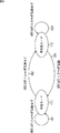
図6に示されるように、被写体の撮影装置50の撮影角度に対する動き(相対角度変化量)のモードには、安定モード171と不安定モード172の2つのモードが存在する。
As shown in FIG. 6, there are two modes, a
例えば、1つ前の区間におけるモードが安定モード171であったとする。その場合、モードフラグ142には安定モード171を示す値がセットされる。モード判別部141は、そのモードフラグ142を参照し、安定モード171であると判定すると、閾値保持部143より、安定モード用の閾値αを取得する。なお、ここでは、撮影画像に棒状飽和輝度被写体が含まれない(前回のAF処理のウォブリングにおいて、撮影画像に棒状飽和輝度被写体が含まれないと判定された)ので、安定モード用の閾値として「α」がセットされている。
For example, it is assumed that the mode in the previous section is the
そして、モード判別部141は、相対角度変化量算出部121の正規化部136より供給された相対角度変化量(正規化された差分値)の絶対値(ABS(Absolute)(p0))をその閾値αと比較する。仮に、相対角度変化量の絶対値が閾値α以下であるとすると、モード判別部141は、新たな区間のモードも安定モード171であると判別する。つまり、この区間と1つ前の区間は両方とも安定モード171であるので、矢印181に示されるようにモード変化は発生しない。
Then, the mode discriminating unit 141 calculates the absolute value (ABS (Absolute) (p0)) of the relative angle change amount (normalized difference value) supplied from the
仮に、相対角度変化量の絶対値(ABS(p0))が閾値αより大きい場合、モード判別部141は、新たな区間のモードを不安定モード172であると判別する。つまり、1つ前の区間において安定モード171であったのが、モード変化が発生し、現在の新たなモードは不安定モード172に遷移する。その際、更新確認部144はモード遷移のパターンが矢印182により示される、安定モード171から不安定モード172への遷移であることを確認し、モード更新部145は、モードフラグ142の値を更新する。
If the absolute value (ABS (p0)) of the relative angle change amount is larger than the threshold value α, the mode determination unit 141 determines that the mode of the new section is the
つまりモードフラグ142には、不安定モード172を示す値がセットされるので、モード判別部141は、そのモードフラグ142を参照し、不安定モード172であると判定すると、閾値保持部143より、不安定モード用の閾値βを取得する。そして、モード判別部141は、相対角度変化量算出部121の正規化部136より供給された相対角度変化量(正規化された差分値)の絶対値(ABS(p0))を閾値βと比較する。仮に、相対角度変化量の絶対値(ABS(p0))が閾値β以上であるとすると、モード判別部141は、新たな区間のモードも不安定モード172であると判別する。つまり、この区間と1つ前の区間は両方とも不安定モード172であるので、矢印183に示されるようにモード変化は発生しない。
That is, since the value indicating the
仮に、相対角度変化量の絶対値(ABS(p0))が閾値βより小さい場合、モード判別部141は、新たな区間のモードを安定モード171であると判別する。つまり、1つ前の区間において不安定モード172であったのが、モード変化が発生し、現在の新たなモードは安定モード171に遷移する。その際、更新確認部144はモード遷移のパターンが矢印184により示される、不安定モード172から安定モード171への遷移であることを確認し、モード更新部145は、モードフラグ142の値を更新する。
If the absolute value (ABS (p0)) of the relative angle change amount is smaller than the threshold value β, the mode determination unit 141 determines that the new section mode is the
モード変化パターン判定部146は、矢印182または矢印184のようにモードが遷移する場合、その遷移方向(モード変化パターン)を判定する。AF起動指示出力部123は、その判定結果に基づいて、矢印184のように、不安定モード172から安定モード171に遷移した場合のみ、AF起動指示をAF制御処理部83に出力する。
When the mode changes as indicated by the
つまり、相対角度変化量の絶対値ABS(p0)≦αの場合(矢印181)、ABS(p0)>αの場合(矢印182)、および、ABS(p0)≧βの場合(矢印183)は、AF処理は起動せず、ABS(p0)<βの場合(矢印184)のみAF処理が開始される。換言すると、相対角度変化量のモードが不安定モード172から安定モード171に移行した場合(大きく変化していた相対角度の変化量が徐々に落ち着き、あまり変化しなくなった場合)に、AF処理が開始されることになる。
That is, the absolute value ABS (p0) ≦ α of the relative angle change amount (arrow 181), ABS (p0)> α (arrow 182), and ABS (p0) ≧ β (arrow 183). , AF processing is not started, and AF processing is started only when ABS (p0) <β (arrow 184). In other words, when the mode of the relative angle change amount shifts from the
AF起動制御の具体例として、図7を参照し、撮影装置50をパンニングする場合について説明する。 As a specific example of the AF activation control, a case where the photographing apparatus 50 is panned will be described with reference to FIG.
例えば、図7Aに示されるように、ユーザが撮像装置50を右から左にパン(撮影方向を変化)させ、撮影画枠191の左側にあって撮影画像に写っていなかった被写体(被写体193A)が、撮影画枠191内に入り(被写体193B)、さらに撮影画枠191の右側に出て行く(被写体193C)ように撮影を行うとする。
For example, as shown in FIG. 7A, the user pans the imaging device 50 from right to left (changes the shooting direction), and a subject (subject 193A) that is on the left side of the
このとき、撮影画枠191より中央付近に、撮影画枠191より小さい評価枠192を設け、撮影画像の評価値は、その評価枠192内で算出し、フィールド内輝度積分値は、撮影画枠191全体について算出するものとする。
At this time, an
この場合、評価枠192内に被写体が出入りすると(被写体193B)、評価値が大きく変化する。従って、この評価値の変化に応じてAF処理を起動させると、最終的に撮影画枠191の外に出てしまう被写体に焦点を合わせようとするので、フォーカス位置が移動したときにはその被写体が撮影画枠191内に存在せず、撮影画像は「ぼけ」てしまう。さらに、パンが終了すると評価値が安定してしまうので、AF処理が起動されず、撮影画像は「ぼけ」たままとなってしまう。
In this case, when the subject enters and leaves the evaluation frame 192 (subject 193B), the evaluation value changes greatly. Therefore, when the AF process is activated in accordance with the change in the evaluation value, it tries to focus on the subject that finally goes out of the
これに対して、フィールド内輝度積分値は、図7Aのように撮像装置50がパンニングされると、例えば、図7Bに示されるグラフの曲線194のように変化する。図7Bにおいて、横軸は時間を示し、縦軸はフィールド内輝度積分値を示している。例えば、時刻t1からt2までの間に図7Aに示されるようなパンが行われたとすると、時刻t1まで安定していたフィールド内輝度積分値は、時刻t1から時刻t2の間に大きく変化し、パンが終了した時刻t2以降はまた安定する。つまり、時刻t1まで安定モードであったモードが時刻t1において不安定モードに移行し、時刻t2において再度安定モードに移行する。
On the other hand, when the imaging device 50 is panned as shown in FIG. 7A, the in-field luminance integral value changes, for example, as shown by a
従って、AF起動制御部82によって、上述したようにフィールド内輝度積分値(フィールド内輝度積分値より算出される相対角度変化量の絶対値ABS(p0))を用いてAF起動制御が行われると、時刻t2のタイミング(不安定モードから安定モードへの移行タイミング)でのみAF処理が起動されることになる。つまり、フォーカス位置を制御するためのパラメータである評価値を用いずに、専用のパラメータである相対角度変化量を用いてAF処理の起動制御を行うことにより、撮像装置50(AF起動制御部82)は、不必要なAF処理を容易に低減させることができ、安定したAF処理を実現することができる。例えば、撮像装置50は、このようなAF起動制御を行うことにより、パンニング中の不必要な被写体(被写体193B)への合焦を抑制することができ、上述したように撮影画像のピント(焦点)が「ぼけ」てしまうことを抑制することができる。なお、チルト(チルティング)の場合も同様である。
Therefore, when AF activation control is performed by the AF
以上のように、AF起動制御部82においては、相対角度変化量算出部121がAF処理の起動を制御するパラメータとして、カメラと被写体の相対角度の変化量を算出し、モード変化検出部122が、その変化量のモード変化パターンを特定し、AF起動指示出力部123がそのモード変化パターンに基づいて、AF制御処理部83にAF処理の起動指示を出力する。
As described above, in the AF
また、他の具体例として、撮影画枠191内において被写体が揺れている場合のAF起動制御について説明する。
As another specific example, AF activation control when the subject is shaking in the
例えば、図8Aに示されるように、撮影画枠191内において、被写体193Dが揺れ動き、評価枠192に出入りするような場合、その評価値は大きく変動する。従って、この評価値の変化に応じてAF処理を起動させると、被写体193Dが揺れている間、常にAF処理が行われることになる。AF処理が行われると、例えばウォブリング等により、撮影画像のフォーカス位置が変化する。つまり、被写体193Dが揺れ動いている場合、頻繁に撮影画像のフォーカス位置が変化し続けることになり、撮影画像が、視聴者にとって不快な(違和感のある)画像となってしまう。特に、撮影画像が高品質なHD(High Definition)の場合、画質が高いだけに、視聴者はフォーカス位置の細かな変化まで確認することができ、その不必要なフォーカス位置の変化に対する不快感は、さらに大きなものとなってしまう。
For example, as shown in FIG. 8A, when the subject 193D shakes and moves in and out of the
これに対して、フィールド内輝度積分値は、撮影画枠191全体について算出されるので、図8Aのように被写体193Dが揺れ動いても、例えば、図8Bに示されるグラフの曲線195のように大きく変化しない。図8Bにおいて、横軸は時間を示し、縦軸はフィールド内輝度積分値を示している。撮影画枠191内において被写体193Dが動いても、輝度値の撮影画枠191全体の合計(積分値)は、大きく変化しない。つまり、この場合、相対角度変化量のモードは、常に安定モードとなる。
On the other hand, the integrated luminance value in the field is calculated for the entire
従って、AF起動制御部82によって、上述したようにフィールド内輝度積分値(フィールド内輝度積分値より算出される相対角度変化量の絶対値ABS(p0))を用いてAF起動制御が行われると、AF処理は起動されないことになる。つまり、撮像装置50は、被写体193Dの小さな動きに対しては、細かく合焦させずに、フォーカス位置を安定させる。このようにAF処理の起動を制御することにより、撮像装置50は、不必要な被写体(被写体193D)への合焦を抑制することができ、撮影画像のフォーカス位置を安定させ、フォーカス位置の不要な変化による不快な画像の発生を抑制することができる。
Therefore, when AF activation control is performed by the AF
なお、図7および図8の場合、AF処理の起動を制御するために用いられるフィールド内輝度積分値は、撮影画枠191全体に対して算出され、フォーカス位置を制御するために用いられる評価値は、その撮影画枠191の一部である評価枠192について算出される。一般的に、評価枠192は小さいほど、ユーザは、その評価枠192内に位置させる被写体を特定し易くなるので、合焦させる被写体を特定し易くなり、フォーカス位置の制御が容易になる。従って、このように各値を算出する枠を設定することにより、撮像装置50は、ユーザが容易にフォーカス位置を制御することが出来るようにするとともに、不要なAF処理を抑制し、フォーカス位置を安定させるように、適切なAF起動制御を行うことができる。
In the case of FIGS. 7 and 8, the integrated luminance value in the field used for controlling the activation of the AF process is calculated for the entire
もちろん、フィールド内輝度積分値を算出する範囲は、撮影画枠191の一部の範囲であってもよいし、その場合、撮影画枠191のどの部分であってもよい。また、撮影画枠191内に複数の範囲(フィールド内輝度積分値を算出する範囲)が設定されるようにしてもよいし、その場合、一部が他の範囲の一部に重なるような範囲が設定されるようにしてもよいし、他の範囲を抱含する範囲が設定されるようにしてもよい。
Of course, the range in which the in-field luminance integral value is calculated may be a partial range of the
評価枠192についても同様であり、撮影画枠191のどの部分が評価枠192として設定されるようにしてもよい。また、撮影画枠191全体を評価枠192としてももちろんよい。さらに、撮影画枠191内に複数の評価枠192を設定するようにしてもよいし、その場合、他の評価枠と範囲の一部が重なるように評価枠を設定するようにしてもよいし、他の評価枠を抱合するような評価枠を設定するようにしてもよい。
The same applies to the
フィールド内輝度積分値を算出する範囲の設定と、評価枠192の設定は、基本的に互いに独立しており、例えば両方の範囲を共通としてもよいが、一般的に、上述したように評価枠192は小さい方が望ましく、フィールド内輝度積分値を算出する範囲は、フォーカス位置を安定させる目的のために(被写体の揺れ動きに反応しないように)大きい方が望ましい。
The setting of the range for calculating the in-field luminance integral value and the setting of the
また、フィールド内輝度積分値を算出する範囲が評価枠192の範囲と重なっていない場合、フィールド内輝度積分値と評価値は、互いに異なる被写体に対して影響を受けることになる。一般的には、ユーザが焦点を合わせている被写体の動きに基づいてAF処理の起動を制御するのが自然であるので、そのような目的のためには、フィールド内輝度積分値を算出する範囲が評価枠192の範囲を抱合するのが望ましい。もちろん、敢えてフィールド内輝度積分値を算出する範囲が評価枠192の範囲と重ならないようにし、撮像装置が、焦点を合焦させる被写体と異なる被写体の動きによって生じる輝度値の変化によってAF起動制御を行うようにしてもよい。
If the range for calculating the in-field luminance integral value does not overlap the range of the
例えば、照明を被写体として撮影する場合、その照明が点灯したり消灯したりされると輝度値が変化するので、被写体(照明)の位置が動いていないにも関わらずAF処理が起動される恐れがあるが、所謂、ワイド端の撮影時のように、被写体(照明)が例えば撮影画枠191の半分程度しか占めないように撮影が行われる場合であれば、フィールド内輝度積分値を算出する範囲が、その被写体(照明)が写されていない部分に設定されている(評価枠192と重ならないように範囲が設定されている)ことにより、撮像装置50は、照明の点灯や消灯(被写体の輝度変化)の影響を受けずにAF起動制御を行うことができ、不要なAF処理を低減させることができ、撮影画像のフォーカス位置を適切に安定させることができる。
For example, when shooting with illumination as a subject, the brightness value changes when the illumination is turned on or off, so AF processing may be activated even though the subject (illumination) position is not moving However, in the case where shooting is performed so that the subject (illumination) occupies only about half of the
さらに、フィールド内輝度積分値を算出する範囲は、予め定められた範囲であってもよいし、ユーザが、撮影前や撮影中等に、撮影画枠191の任意の位置に設定することができるようにしてもよい。また、その際、そのフィールド内輝度積分値を算出する範囲の大きさおよび形状もユーザにより設定することができるようにしてもよい。さらに、フィールド内輝度積分値を算出する範囲としての候補が予め複数用意され、ユーザが撮影前や撮影中等にそれらの候補の中から任意の領域を選択し、フィールド内輝度積分値を算出する範囲として設定するようにしてもよい。なお、評価枠192についても同様であり、予め定められた領域であってもよいし、ユーザが撮影前や撮影中等に自由に設定することができるようにしてもよいし、予め用意された選択肢の中からユーザが選択的に設定することができうようにしてもよい。
Further, the range in which the in-field luminance integral value is calculated may be a predetermined range, or the user can set it at an arbitrary position in the
フィールド内輝度積分値を算出する範囲や評価枠192が予め設定されていれば、ユーザは撮影時にそれらを設定する必要が無く、撮影を容易に行うことができる。また、フィールド内輝度積分値を算出する範囲や評価枠192をユーザが自由に設定することができるようになされていれば、環境や被写体等の撮影条件により適した範囲設定が可能になり、ユーザの意図に沿った、より好ましいAF処理を実現することができる。さらに、その範囲の設定をユーザが選択的に行うことができるようにすることにより、ユーザは容易に範囲設定を行うことができる。
If the range for calculating the integrated luminance value in the field and the
なお、フィールド内輝度積分値を算出する範囲の設定方法として、ユーザがフィールド内輝度積分値を算出しない範囲を設定することができるようにしてももちろんよい。つまり、この場合撮像装置は、ユーザに指定された範囲以外の部分の輝度値を積分し、フィールド内輝度積分値を算出し、その値を用いてAF起動制御を行う。 Of course, as a method of setting the range for calculating the in-field luminance integral value, the user may set a range in which the in-field luminance integral value is not calculated. That is, in this case, the imaging apparatus integrates the luminance values outside the range designated by the user, calculates the integrated luminance value in the field, and performs AF activation control using the value.
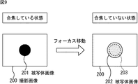
次に、撮影画像における飽和輝度数とフォーカス移動の関係について図9乃至図11を参照して説明する。図9乃至図11のいずれの場合も、左側に示される撮影画像200は、被写体に合焦している状態の撮影画像であり、右側に示される撮影画像200は、ウォブリング動作によりフォーカス位置が被写体からずれた状態の撮影画像である。
Next, the relationship between the saturation luminance number and the focus movement in the captured image will be described with reference to FIGS. 9 to 11, the photographed
図9は、光源等ではない通常の被写体を撮影した場合の撮影画像の例を示す図である。 FIG. 9 is a diagram illustrating an example of a captured image when a normal subject that is not a light source or the like is captured.
撮影画像200において、この通常の被写体の画像は、焦点がこの通常の被写体に合焦しているとき、図9の左側に示されるように、輝度が飽和していない、輪郭のはっきりした被写体画像201となる。この状態から、フォーカス位置が移動し(フォーカス移動し)、被写体に焦点が合焦しなくなると、通常の被写体の画像は、図9の右側に示されるように、輪郭がにじんでぼやけた被写体画像202となる。この被写体画像202は、点線203で示される被写体画像201(合焦している状態の被写体画像)の大きさより大きく表示される。また、そのぼやけた分、被写体画像202の各画素の輝度値は、被写体画像201の場合よりも低下する(暗くなる)。
In the photographed
従って、この場合、撮影画像200全体の輝度値の合計(つまりフィールド内輝度積分値)は大きく変化せず、相対角度変化量のモードは安定モード171であると判定されるので、AF処理(不要なAF処理)は起動されない。
Accordingly, in this case, the sum of the brightness values of the entire photographed image 200 (that is, the integrated brightness value in the field) does not change greatly, and it is determined that the relative angle change mode is the
図10は、円形の光源等のように撮影画像の輝度が飽和する被写体である飽和輝度被写体を撮影した場合の撮影画像の例を示す図である。 FIG. 10 is a diagram illustrating an example of a captured image when a saturated luminance subject that is a subject in which the luminance of the captured image is saturated, such as a circular light source.
この場合の撮影画像200において、合焦時の円形の飽和輝度被写体の画像は、図10の左側に示されるように、輪郭のはっきりした円形の飽和輝度被写体画像204となる。ただし、この飽和輝度被写体画像204の各画素の輝度は飽和している。この状態から、フォーカス位置が移動し、飽和輝度被写体に焦点が合焦しなくなると、この飽和輝度被写体の画像は、図10の右側に示されるように、輪郭がにじんでぼやけた飽和輝度被写体画像205となる。この飽和輝度被写体画像205は、点線206で示される飽和輝度被写体画像204(合焦している状態の飽和輝度被写体画像)の大きさより大きく表示される。ただし、この場合、飽和輝度被写体画像204の輝度値が飽和しているので、フォーカス位置がずれても輝度値は飽和したままとなる。
In the captured
従って、この場合、撮影画像200全体の輝度値の合計(つまりフィールド内輝度積分値)は、図10の右側の灰色に示される部分(点線206と飽和輝度被写体画像205の外枠の間の部分(飽和輝度被写体画像の、焦点が被写体からずれることにより大きくなった部分))の輝度値の増加分だけ増加する。
Therefore, in this case, the sum of the luminance values of the entire photographed image 200 (that is, the integrated luminance value in the field) is the portion shown in gray on the right side of FIG. 10 (the portion between the
しかしながら、ウォブリング動作においてフォーカス位置の移動幅は微小であるので、飽和輝度被写体画像205と飽和輝度被写体画像204の面積の差は、飽和輝度被写体画像204全体の面積と比較して微小となる。従って、この輝度値の増加分によって撮影画像200全体の輝度値の合計(つまりフィールド内輝度積分値)は大きく変化しない。また、元々の飽和輝度被写体画像204の面積が撮影画像200の画像サイズに対して十分に小さければ、輝度値の増加分は、撮影画像200全体の輝度値の合計(つまりフィールド内輝度積分値)に対して微小となるので、この増加分によってフィールド内輝度積分値は大きく変化しない。従って、相対角度変化量のモードは安定モード171であると判定されるので、AF処理(不要なAF処理)は起動されない。
However, since the moving range of the focus position is small in the wobbling operation, the difference in area between the saturated luminance
図11は、細い棒状の光源等のように撮影画像の輝度が飽和する棒状の被写体である棒状飽和輝度被写体を撮影した場合の撮影画像の例を示す図である。 FIG. 11 is a diagram illustrating an example of a captured image when a rod-shaped saturated luminance subject that is a rod-shaped subject in which the luminance of the captured image is saturated, such as a thin rod-shaped light source.
この場合の撮影画像200において、合焦時の棒状飽和輝度被写体の画像は、図11の左側に示されるように、輪郭のはっきりした棒状飽和輝度被写体画像207となる。ただし、棒状飽和輝度被写体画像207の各画素の輝度は飽和している。この状態から、フォーカス位置が移動し、棒状飽和輝度被写体に焦点が合焦しなくなると、この棒状飽和輝度被写体の画像は、図11の右側に示されるように、輪郭がにじんでぼやけた棒状飽和輝度被写体画像208となる。この棒状飽和輝度被写体画像208は、点線209で示される棒状飽和輝度被写体画像207(合焦している状態の棒状飽和輝度被写体画像)の大きさより大きく表示される。ただし、この場合、棒状飽和輝度被写体画像207の輝度値が飽和しているので、フォーカス位置がずれても輝度値は飽和したままとなる。
In the photographed
この場合、棒状飽和輝度被写体画像207が細い棒状の画像であるので、棒状飽和輝度被写体画像208と棒状飽和輝度被写体画像207の面積の差は、棒状飽和輝度被写体画像207全体の面積と比較して無視できないほど大きくなる。
In this case, since the rod-like saturated luminance
例えば、元々の棒状飽和輝度被写体画像207が1画素×100画素の画像であり、焦点が棒状飽和輝度被写体からずれることにより、その画像が1画素分ずつ広がるとすると、棒状飽和輝度被写体画像208は、3画素×102画素の画像となり、棒状飽和輝度被写体画像207の3倍以上の面積となる。因みに、図10において、円形の飽和輝度被写体画像204が半径10画素の円状の画像であり、焦点が飽和輝度被写体からずれることにより、その画像が1画素分ずつ広がるとすると、飽和輝度被写体画像205は、半径11画素の円状の画像となり、飽和輝度被写体画像204とほぼ同じ面積(1.2倍程度)となる。
For example, if the original bar-shaped saturated luminance
さらに、例えば、ブラインド越しに光源を撮影したときの画像ように、撮影画像200全体に、この棒状飽和輝度被写体画像207が数画素置きに分布しているような場合、この焦点のずれによる(ウォブリングによる)輝度値の増加分は、撮影画像200全体の輝度値の合計(つまりフィールド内輝度積分値)に対して無視できないほど大きなものとなる恐れがある。
Further, for example, when the rod-like saturated luminance
つまり、図11のように細い棒状の飽和輝度被写体を撮影する場合、図10の場合と異なり、ウォブリング等のフォーカス位置の変化によって生じるフィールド内輝度積分値の変化が十分に大きくなる恐れがある。このような場合、モード判別部141が、図9の例のように、通常の被写体のときと同様に相対角度変化量のモードを判別すると、不安定モード172であると判定してしまい、AF処理終了後に(フォーカス位置が安定した後に)、モード変化パターン判定部146によって、その不安定モード172から安定モード171に移行したと判定され、再度AF処理(不要なAF処理)が起動されてしまう恐れがある。
That is, when shooting a thin bar-like saturated luminance subject as shown in FIG. 11, unlike in the case of FIG. 10, the change in the in-field luminance integral value caused by the change in the focus position such as wobbling may become sufficiently large. In such a case, if the mode determination unit 141 determines the relative angle change mode as in the case of a normal subject as in the example of FIG. After the processing is completed (after the focus position is stabilized), the mode change
起動条件調整部84は、モード判別に用いる閾値(起動条件)を調整することにより、このような事態の発生を低減させる。
The activation
つまり、起動条件調整部84の閾値選択部155は、ウォブリング中の飽和輝度数の変化(最大値と最小値の比)の大小を、上述した式(2)の条件式を用いて判定することにより、被写体が棒状飽和輝度被写体であるか否かを判定し、その判定結果によって安定モード用閾値を選択する。例えば、閾値選択部155は、被写体が棒状飽和輝度被写体でない場合、安定モード用閾値として値αを選択して閾値保持部143にセットし、被写体が棒状飽和輝度被写体である場合、安定モード用閾値として値αより大きい(条件の厳しい)値(α×3)を選択して閾値保持部143にセットする。
That is, the threshold
従って、図12に示されるように、モードは、相対角度変化量の絶対値が閾値(α×3)を超えないと、安定モード171から不安定モード172に移行しない。従って、相対角度変化量の絶対値が閾値(α×3)以下であると、新たな区間のモードも安定モード171であると判別され、矢印211に示されるようにモード変化は発生しない。相対角度変化量の絶対値が閾値(α×3)より大きい場合のみ、モード変化が発生し、矢印212のように、モードは、安定モード171から不安定モード172に遷移される。
Therefore, as shown in FIG. 12, the mode does not shift from the
このように、図11に示されるような棒状飽和輝度被写体を撮影する場合においても、閾値選択部155が、安定モード用閾値として、棒状飽和輝度被写体以外の被写体を撮影する場合の閾値よりも大きな値を選択し、相対角度変化量のモードを安定モード171から不安定モード172に移行させる条件をより厳しくするので、AF起動制御部82は、不要なAF処理の起動を抑制することができる。これにより、撮像装置50は、より的確なAF処理を実現し、高品質な撮影画像が得られるようにすることができる。
In this way, even when shooting a rod-like saturated luminance subject as shown in FIG. 11, the
なお、閾値選択部155が安定モード用閾値として通常以外の閾値を選択する被写体は、上述した棒状飽和輝度被写体でなくてもよく、その被写体を判別可能な条件式が設定可能であればどのような被写体であってもよい。換言すると、この閾値選択に用いられる条件式は、上述した式(2)以外の式であってもよい。さらに、閾値選択部155に選択される閾値の値もどのような値であってもよく、その選択肢の数は3つ以上であってもよい(条件式の数が複数であってもよい)。
Note that the subject for which the
次に、上述した各処理の流れについて説明する。最初に、図13のフローチャートを参照して、AF起動制御部82によるAF起動制御処理の流れの例を説明する。
Next, the flow of each process described above will be described. First, an example of the flow of AF activation control processing by the AF
信号処理部73より画像信号(フィールド画像またはフレーム画像)が供給されると、AF起動制御部82の相対角度変化量算出部121は、ステップS1において相対角度変化量算出処理を実行する。相対角度変化量算出処理の詳細については、図14のフローチャートを参照して後述する。
When an image signal (field image or frame image) is supplied from the
相対角度変化量算出処理を終了すると、モード変化検出部122は、ステップS2においてモード変化検出処理を実行する。モード変化検出処理の詳細は、図15のフローチャートを参照して後述する。 When the relative angle change amount calculation process ends, the mode change detection unit 122 executes the mode change detection process in step S2. Details of the mode change detection process will be described later with reference to the flowchart of FIG.
モード変化検出処理を終了すると、ステップS3において、AF起動指示出力部123は、モード変化検出処理結果に基づいて、AF処理を開始するか否かを判定する。上述したように、相対角度変化量のモードが不安定モード172から安定モード171に移行したと判定され、AF処理を開始すると判定した場合、AF起動指示出力部123は、ステップS4においてAF起動指示をAF制御処理部83に出力し、AF処理を起動させた後、AF起動制御処理を終了する。また、ステップS3において、相対角度変化量のモードが不安定モード172から安定モード171に移行していないと判定され、AF処理を開始しないと判定した場合、AF起動指示出力部123は、ステップS4の処理を省略し、AF起動制御処理を終了する。
When the mode change detection process ends, in step S3, the AF activation instruction output unit 123 determines whether to start the AF process based on the mode change detection process result. As described above, when it is determined that the relative angle change mode has shifted from the
次に、図13のステップS1において実行される相対角度変化量算出処理の詳細な流れの例について図14のフローチャートを参照して説明する。 Next, an example of a detailed flow of the relative angle change amount calculation process executed in step S1 of FIG. 13 will be described with reference to the flowchart of FIG.
画像信号が信号処理部73より供給され、相対角度変化量算出処理が開始されると、フィールド内輝度積分値算出部131は、最初に、ステップS21において、供給された画像信号に基づいて、フィールドの所定の領域(撮影画枠内の、領域設定部132により設定されている領域)内の輝度値の積分値(フィールド内輝度積分値)を算出する。
When the image signal is supplied from the
ステップS22において、区間別輝度積分平均値算出部133は、区間別輝度積分平均値保持部134と連携しながら、区間毎に輝度積分値の平均値(区間別輝度積分平均値)を求める。差分値算出部135は、ステップS23において、隣り合う区間(最新の区間と1つ前の区間)の区間別輝度積分平均値の差分値を算出する。ステップS24において、正規化部136は、ステップS23において算出された差分値を最新のフィールド内輝度積分値とフィールド数で正規化し、相対角度変化量を求める。ステップS24の処理が終了すると、正規化部136は、相対角度変化量算出処理を終了し、処理を図13のステップS1に戻し、ステップS2以降の処理を行う。
In step S <b> 22, the section-by-section luminance integral average value calculation unit 133 obtains the average value of the luminance integral values (section-by-section luminance integral average value) for each section in cooperation with the section-by-section luminance integral average value holding unit 134. In step S <b> 23, the difference value calculation unit 135 calculates a difference value between the integrated luminance average values for the adjacent sections (the latest section and the previous section). In step S24, the
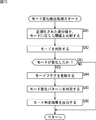
次に、図13のステップS2において実行されるモード変化検出処理の詳細の流れの例について図15のフローチャートを参照して説明する。 Next, an example of the detailed flow of the mode change detection process executed in step S2 of FIG. 13 will be described with reference to the flowchart of FIG.
モード変化検出処理が開始されると、モード判別部141は、ステップS41において、正規化された差分値である相対角度変化量を、モードフラグ142および閾値保持部143を参照して得られる、1区間前のモードに応じた閾値(起動条件調整部84により選択されてセットされた閾値)と比較し、ステップS42において、最新のモードを判別する。ステップS43において、更新確認部144は、モードが変化したか否かを確認し、変化したと判定した場合、処理をステップS44に進める。ステップS44において、モード更新部145は、モードフラグ142の値を更新する。モード変化パターン判定部146は、ステップS45において、モード変化パターンを判定し、ステップS46において、モード判定結果をAF起動指示出力部123に出力し、モード変化検出処理を終了し、処理を図13のステップS2に戻す。AF起動制御部82は、ステップS3以降の処理を実行する。
When the mode change detection process is started, the mode determination unit 141 obtains the relative angle change amount, which is a normalized difference value, with reference to the
また、ステップS43において、モードが変化していないと判定した場合、更新確認部144は、ステップS44乃至ステップS46の処理を省略し、モード変化検出処理を終了し、処理を図13のステップS2に戻す。AF起動制御部82は、ステップS3以降の処理を実行する。
If it is determined in step S43 that the mode has not changed, the update confirmation unit 144 omits steps S44 to S46, ends the mode change detection process, and shifts the process to step S2 in FIG. return. The AF
以上のように各処理を行うことにより、AF起動制御部82は、不必要なAF処理を容易に低減させ、より的確なAF処理を実現し、高品質な撮影画像が得られるようにすることができる。
By performing each processing as described above, the AF
次に、図13のステップS4の処理に対応し、出力されたAF起動指示に従って開始されるワンショットAF制御処理について、図16のフローチャートを参照して説明する。 Next, the one-shot AF control process started in accordance with the output AF activation instruction corresponding to the process in step S4 in FIG. 13 will be described with reference to the flowchart in FIG.
ワンショットAF制御処理を開始すると、AF制御処理部83は、最初に、ステップS61において、起動条件調整部84に起動条件調整処理を開始させる。この起動条件調整処理の詳細は、図17のフローチャートを参照して後述する。ステップS62において、AF制御処理部83は、駆動制御部64を制御し、ウォブリングレンズ62を駆動させるウォブリング処理を行い、フォーカスレンズ61を移動させる向きを決定する。このときのウォブリング中の撮影画像から、起動条件調整部84は、上述したように棒状飽和輝度被写体の存在を判定し、その有無に基づいてモード判別用の閾値を選択して設定する。ウォブリング処理が終了すると、AF制御処理部83は、ステップS63において、駆動制御部64を制御し、ウォブリング処理により決定された向きにフォーカスレンズ61を移動させながら、評価値算出部81を用いて撮影画像の「ぼけ」を評価する評価値を算出し、その評価値に基づいて最適なフォーカス位置を検索するフォーカス位置検索処理を行う。最適なフォーカス位置が検索されると、AF制御処理部83は、駆動制御部64を制御し、検索された最適なフォーカス位置に焦点を合わせるようにフォーカスレンズ61を駆動させる、合焦処理を行う。焦点が合焦すると、AF制御処理部83は、ワンショットAF制御処理を終了する。
When the one-shot AF control process is started, the AF
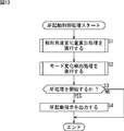
次に、図16のステップS61の処理によりAF制御処理部83より開始を指示された起動条件調整部84により開始される起動条件調整処理について、図17のフローチャートを参照して説明する。
Next, the activation condition adjustment process started by the activation
起動条件調整処理が開始されると、起動条件調整部84の飽和輝度数算出部151は、ステップS81において、信号処理部73より取得した画像信号を用いて、ウォブリング中の撮影画像の飽和輝度数を算出する。つまり、飽和輝度数算出部151は、Mフィールド分のフィールド画像信号のそれぞれについて飽和輝度数を算出する。飽和輝度数算出部151は、算出した飽和輝度数の情報を順次、飽和輝度数履歴保持部152に供給し、保持させる。
When the activation condition adjustment process is started, the saturated luminance number calculation unit 151 of the activation
飽和輝度数履歴保持部152は、ステップS82において、その供給された飽和輝度数の情報を履歴として保持する。既にMフィールド分の履歴を保持している場合、飽和輝度数履歴保持部152は、保持している最も古い履歴を削除して、新しい飽和輝度数の情報を保持する。
In step S82, the saturated luminance number
ステップS83において、飽和輝度数最大値検索部153は、飽和輝度数履歴保持部152に保持されている履歴から飽和輝度数の最大値を検索し、その値を取得する。飽和輝度数最大値検索部153は、取得した最大値を閾値選択部155に供給し、飽和輝度数最小値検索部154に処理終了を伝える。飽和輝度数最小値検索部154は、ステップS84において、飽和輝度数履歴保持部152に保持されている履歴から飽和輝度数の最小値を検索し、その値を取得する。飽和輝度数最小値検索部154は、取得した最小値を閾値選択部155に供給するとともに処理終了を伝える。
In step S83, the saturated luminance number maximum
閾値選択部155は、ステップS85において、式(2)に示される条件式を演算する閾値選択用演算を行い、ステップS86において、その演算結果に基づいて、式(2)に示される条件式が満たされるか否かを判定する。式(2)を満たすと判定した場合、閾値選択部155は、処理をステップS87に進め、例えば棒状飽和輝度被写体に対する閾値である第1閾値(例えば、閾値(α×3))を選択し、その閾値を閾値更新部156に供給する。閾値が供給されると閾値更新部156は、ステップS88において、その閾値を用いて閾値保持部143に保持されている閾値を更新する。更新が終了すると閾値更新部156は、起動条件調整処理を終了する。
In step S85, the
また、ステップS86において、式(2)を満たさないと判定した場合、閾値選択部155は、処理をステップS89に進め、例えば通常の被写体に対する閾値である第2閾値(例えば、閾値α)を選択し、その閾値を閾値更新部156に供給する。閾値が供給されると閾値更新部156は、ステップS88において、その閾値を用いて閾値保持部143に保持されている閾値を更新する。更新が終了すると閾値更新部156は、起動条件調整処理を終了する。
If it is determined in step S86 that Expression (2) is not satisfied, the
以上のように、輝度条件調整部84が、撮影画像の飽和輝度数を用いて、起動条件(閾値)を調整するので、撮像装置50は、棒状飽和輝度被写体を撮影するような特殊な被写体の場合であっても、不必要なAF処理を容易に低減させ、より的確なAF処理を実現し、高品質な撮影画像が得られるようにすることができる。
As described above, the luminance
なお、上述したように、輝度条件調整部84により安定モード用閾値が高く設定された場合(α×3)であっても、飽和輝度被写体の存在は、フィールド内輝度積分値に大きく影響をおよぼすため、パンニングやチルティングが行われたり、被写体(棒状飽和輝度被写体)が移動したりしたときの輝度変化は閾値に対して十分大きく、閾値が低く設定された場合(α)と同様に不安定モードに移行する。すなわち、上述した輝度条件調整部84による閾値の調整は、閾値の変更率を調整する等して、パンニングやチルティング等の際のモード判定には大きく影響せず、AF起動の不要な妨げとならないように行われる。
As described above, even when the threshold value for the stable mode is set high by the luminance condition adjusting unit 84 (α × 3), the presence of the saturated luminance subject greatly affects the in-field luminance integrated value. Therefore, the brightness change when panning or tilting is performed or the subject (bar-like saturated brightness subject) is moved is sufficiently large with respect to the threshold, and is unstable as in the case where the threshold is set low (α) Enter mode. That is, the adjustment of the threshold value by the brightness
なお、以上においては、輝度条件調整部84が、起動条件(閾値)の調整を、AF処理のウォブリング時の撮影画像を用いて行うように説明したが、処理の実行タイミングはこれに限らず、いつ開始するようにしてもよい。例えば、輝度条件調整部84が、定期的に起動条件調整処理を開始するようにしてもよいし、上述したのと異なるきっかけにより起動条件調整処理を開始するようにしてもよい。また、飽和輝度数を算出するためにウォブリング動作を行うようにしてもよい。
In the above description, the luminance
なお、以上において、AF処理の起動を制御するパラメータであるカメラと被写体の相対角度の変化量は、撮影画像の輝度値を用いた値であるように説明したが、これに限らず、例えば、コントラストに関する値を用いる等、輝度値以外の値を用いて算出される値であってもよい。また、演算方法も上述した以外の方法であってもよい。例えば、区間毎にフィールド内輝度積分値の平均値を算出し、その平均値を用いて相対角度変化量を算出するように説明したが、これに限らず、例えば、輝度値の積分値でなく平均値を用いるようにしてもよいし、フィールド内輝度積分値の区間毎の平均値の代わりに、フィールド内輝度積分値の合計値を用いて相対角度変化量を算出するようにしてもよい。フィールド単位で求められた輝度値の平均値の、区間毎の平均値を用いて相対角度変化量を算出するようにしてももちろんよい。また、正規化も、最新のフィールド内輝度値とフィールド数を用いる代わりに、区間別輝度積分平均値等の他の値を用いるようにしてもよい。また、正規化を行わないようにしてもよい。 In the above description, the amount of change in the relative angle between the camera and the subject, which is a parameter for controlling the activation of the AF processing, has been described as a value using the luminance value of the captured image. It may be a value calculated using a value other than the luminance value, such as using a value related to contrast. Also, the calculation method may be a method other than those described above. For example, the average value of the integrated luminance value in the field is calculated for each section, and the relative angle change amount is calculated using the average value. However, the present invention is not limited to this. The average value may be used, or the relative angle change amount may be calculated using the total value of the in-field luminance integral values instead of the average value of the in-field luminance integral values for each section. Of course, the relative angle change amount may be calculated by using the average value of the luminance values obtained in field units for each section. Also, in normalization, instead of using the latest in-field luminance value and the number of fields, other values such as the luminance integrated average value for each section may be used. Further, normalization may not be performed.
また、AF起動制御用のパラメータとして、カメラと被写体の相対角度の変化量以外の値を用いるようにしてもよい。さらに、AF起動制御用のパラメータとして、カメラと被写体の相対角度の変化量と、それ以外の値を併用するようにしてもよい。 Further, as the AF activation control parameter, a value other than the change amount of the relative angle between the camera and the subject may be used. Further, as a parameter for AF activation control, a change amount of the relative angle between the camera and the subject and other values may be used together.
上述した一連の処理は、ハードウェアにより実行させることもできるし、ソフトウエアにより実行させることもできる。上述した一連の処理をソフトウエアにより実行させる場合には、そのソフトウエアを構成するプログラムが、ネットワークや記録媒体からインストールされる。 The series of processes described above can be executed by hardware or can be executed by software. When the above-described series of processing is executed by software, a program constituting the software is installed from a network or a recording medium.
この記録媒体は、例えば、上述したように、装置本体とは別に、ユーザにプログラムを配信するために配布されるリムーバブルメディア97により構成されるだけでなく、装置本体に予め組み込まれた状態でユーザに配信される、プログラムが記録されているROM91や、記憶部94に含まれるハードディスクなどで構成される。
For example, as described above, this recording medium is configured not only by the removable medium 97 distributed to distribute the program to the user, but also by being installed in the apparatus main body in advance. And a
なお、本明細書において、記録媒体に記録されるプログラムを記述するステップは、記載された順序に沿って時系列的に行われる処理はもちろん、必ずしも時系列的に処理されなくとも、並列的あるいは個別に実行される処理をも含むものである。 In the present specification, the step of describing the program recorded on the recording medium is not limited to the processing performed in chronological order according to the described order, but is not necessarily performed in chronological order. It also includes processes that are executed individually.
また、本明細書において、1つの装置として説明した構成を分割し、複数の装置として構成するようにしてもよい。逆に、以上において複数の装置として説明した構成をまとめて1つの装置として構成されるようにしてもよい。また、上述した以外の構成を付加するようにしてももちろんよい。さらに、装置全体としての構成や動作が実質的に同じであれば、ある部分の構成の一部を他の部分の構成に含めるようにしてもよい。 Further, in this specification, the configuration described as one device may be divided and configured as a plurality of devices. Conversely, the configurations described above as a plurality of devices may be combined into a single device. Of course, configurations other than those described above may be added. Further, if the configuration and operation of the entire apparatus are substantially the same, a part of the configuration of a certain part may be included in the configuration of the other part.
50 撮像装置, 51 AF駆動部, 52 画像処理部, 53 AF制御部, 61 フォーカスレンズ, 62 ウォブリングレンズ, 63 レンズ駆動部, 64 駆動制御部, 73 信号処理部, 81 評価値算出部, 82 AF起動制御部, 83 AF制御処理部, 84 起動条件調整部, 121 相対角度変化量算出部, 122 モード変化検出部, 123 AF起動指示出力部, 131 フィールド内輝度積分値算出部, 132 領域設定部, 133 区間別輝度積分平均値算出部, 134 区間別輝度積分平均値保持部, 135 差分値算出部, 136 正規化部, 141 モード判別部, 142 モードフラグ, 143 閾値保持部, 144 更新確認部, 145 モード更新部, 146 モード変化パターン判定部, 151 飽和輝度数履歴保持部152, 153 飽和輝度数最大値検索部, 154 飽和輝度数最小値検索部, 155 閾値選択部, 156 閾値更新部 171 安定モード, 172 不安定モード, 191 撮影画枠, 192 評価枠, 193A乃至193D 被写体
50 imaging device, 51 AF drive unit, 52 image processing unit, 53 AF control unit, 61 focus lens, 62 wobbling lens, 63 lens drive unit, 64 drive control unit, 73 signal processing unit, 81 evaluation value calculation unit, 82 AF Activation control unit, 83 AF control processing unit, 84 activation condition adjustment unit, 121 relative angle change amount calculation unit, 122 mode change detection unit, 123 AF activation instruction output unit, 131 in-field luminance integral value calculation unit, 132 region setting unit , 133 Interval-specific luminance integral average value calculation unit, 134 Interval-specific luminance integral average value holding unit, 135 Difference value calculation unit, 136 Normalization unit, 141 Mode determination unit, 142 Mode flag, 143 Threshold holding unit, 144 Update confirmation unit , 145 mode update unit, 146 mode change pattern determination unit, 151 Saturated luminance number
Claims (4)
前記撮像装置により撮像される撮像画像を構成する画素の輝度値の積分値を算出する積分値算出手段と、
第1の時間範囲に撮像された撮像画像について算出された積分値と、前記第1の時間範囲とは異なる第2の時間範囲に撮像された撮像画像について算出された積分値との変化の割合を表す積分変化量を算出する積分変化量算出手段と、
安定モードまたは不安定モードに設定されるモードに対応し、前記積分変化量と比較されるモード変更用閾値を調整する閾値調整手段と、
前記モードが前記安定モードに設定されている場合、前記積分変化量が前記安定モード用に調整された前記モード変更用閾値よりも大きいときには、前記モードを前記安定モードから前記不安定モードに変更し、
前記モードが前記不安定モードに設定されている場合、前記積分変化量が前記不安定モード用に調整された前記モード変更用閾値よりも小さいときには、前記モードを前記不安定モードから前記安定モードに変更するモード変更手段と、
前記モードが前記不安定モードから前記安定モードに変更されたことに対応して、前記駆動部を制御して前記フォーカス位置を制御するフォーカス位置制御処理を実行する実行手段と、
前記フォーカス位置制御処理の実行中に撮像された複数の撮像画像毎に、前記撮像画像を構成する画素のうち、飽和した輝度値を有する画素の個数である飽和輝度数を算出する飽和輝度数算出手段と、
前記複数の撮像画像における、前記飽和輝度数の変化の割合を表す飽和輝度数変化量を算出する飽和輝度数変化量算出手段と
を備え、
前記閾値調整手段は、前記モードが前記安定モードに設定されている場合、
前記飽和輝度数変化量が閾値調整用閾値未満であるときには、前記安定モード用の前記モード変更用閾値を第1の値に調整し、
前記飽和輝度数変化量が前記閾値調整用閾値よりも大きいときには、前記安定モード用の前記モード変更用閾値を前記第1の値よりも大きな第2の値に調整する
制御装置。 In a control device that executes processing related to control of a drive unit that adjusts a focus position when driving an optical element of an imaging device to image a subject,
An integral value calculating means for calculating an integral value of luminance values of pixels constituting a captured image captured by the imaging device;
Ratio of change between the integral value calculated for the captured image captured in the first time range and the integral value calculated for the captured image captured in the second time range different from the first time range Integral change amount calculating means for calculating an integral change amount representing
Corresponding to a mode set to a stable mode or an unstable mode, a threshold adjusting means for adjusting a mode change threshold to be compared with the integral change amount;
When the mode is set to the stable mode, the mode is changed from the stable mode to the unstable mode when the integral change amount is larger than the mode change threshold adjusted for the stable mode. ,
When the mode is set to the unstable mode, the mode is changed from the unstable mode to the stable mode when the integral change amount is smaller than the mode change threshold adjusted for the unstable mode. Mode changing means for changing;
In response to the mode being changed from the unstable mode to the stable mode, execution means for executing a focus position control process for controlling the focus position by controlling the drive unit;
For each of a plurality of captured images captured during execution of the focus position control process, a saturated luminance number calculation that calculates a saturated luminance number that is the number of pixels having a saturated luminance value among pixels constituting the captured image. Means,
A saturated luminance number change amount calculating means for calculating a saturated luminance number change amount representing a rate of change of the saturated luminance number in the plurality of captured images;
With
The threshold adjustment means, when the mode is set to the stable mode,
When the saturation luminance number change amount is less than a threshold adjustment threshold, the mode change threshold for the stable mode is adjusted to a first value,
When the saturation luminance number change amount is larger than the threshold adjustment threshold, the mode change threshold for the stable mode is adjusted to a second value larger than the first value.
Control apparatus.
請求項1に記載の制御装置。 The control device according to claim 1.
前記撮像装置により撮像される撮像画像を構成する画素の輝度値の積分値を算出する積分値算出ステップと、
第1の時間範囲に撮像された撮像画像について算出された積分値と、前記第1の時間範囲とは異なる第2の時間範囲に撮像された撮像画像について算出された積分値との変化の割合を表す積分変化量を算出する積分変化量算出ステップと、
安定モードまたは不安定モードに設定されるモードに対応し、前記積分変化量と比較されるモード変更用閾値を調整する閾値調整ステップと、
前記モードが前記安定モードに設定されている場合、前記積分変化量が前記安定モード用に調整された前記モード変更用閾値よりも大きいときには、前記モードを前記安定モードから前記不安定モードに変更し、
前記モードが前記不安定モードに設定されている場合、前記積分変化量が前記不安定モード用に調整された前記モード変更用閾値よりも小さいときには、前記モードを前記不安定モードから前記安定モードに変更するモード変更ステップと、
前記モードが前記不安定モードから前記安定モードに変更されたことに対応して、前記駆動部を制御して前記フォーカス位置を制御するフォーカス位置制御処理を実行する実行ステップと、
前記フォーカス位置制御処理の実行中に撮像された複数の撮像画像毎に、前記撮像画像を構成する画素のうち、飽和した輝度値を有する画素の個数である飽和輝度数を算出する飽和輝度数算出ステップと、
前記複数の撮像画像における、前記飽和輝度数の変化の割合を表す飽和輝度数変化量を算出する飽和輝度数変化量算出ステップと
を含み、
前記閾値調整ステップは、前記モードが前記安定モードに設定されている場合、
前記飽和輝度数変化量が閾値調整用閾値未満であるときには、前記安定モード用の前記モード変更用閾値を第1の値に調整し、
前記飽和輝度数変化量が前記閾値調整用閾値よりも大きいときには、前記安定モード用の前記モード変更用閾値を前記第1の値よりも大きな第2の値に調整する
制御方法。 A control method for a control device that executes processing related to control of a drive unit that adjusts a focus position when driving an optical element of an imaging device to image a subject,
An integral value calculating step for calculating an integral value of luminance values of pixels constituting a captured image captured by the imaging device;
Ratio of change between the integral value calculated for the captured image captured in the first time range and the integral value calculated for the captured image captured in the second time range different from the first time range An integral change amount calculating step for calculating an integral change amount representing
A threshold adjustment step for adjusting a mode change threshold to be compared with the integral change amount corresponding to the mode set to the stable mode or the unstable mode;
When the mode is set to the stable mode, the mode is changed from the stable mode to the unstable mode when the integral change amount is larger than the mode change threshold adjusted for the stable mode. ,
When the mode is set to the unstable mode, the mode is changed from the unstable mode to the stable mode when the integral change amount is smaller than the mode change threshold adjusted for the unstable mode. A mode change step to change;
In response to the mode being changed from the unstable mode to the stable mode, an execution step of executing a focus position control process for controlling the focus position by controlling the drive unit;
For each of a plurality of captured images captured during execution of the focus position control process, a saturated luminance number calculation that calculates a saturated luminance number that is the number of pixels having a saturated luminance value among pixels constituting the captured image. Steps,
A saturated luminance number change amount calculating step for calculating a saturated luminance number change amount representing a rate of change of the saturated luminance number in the plurality of captured images;
Including
In the threshold adjustment step, when the mode is set to the stable mode,
When the saturation luminance number change amount is less than a threshold adjustment threshold, the mode change threshold for the stable mode is adjusted to a first value,
When the saturation luminance number change amount is larger than the threshold adjustment threshold, the mode change threshold for the stable mode is adjusted to a second value larger than the first value.
Control method.
前記撮像装置により撮像される撮像画像を構成する画素の輝度値の積分値を算出する積分値算出ステップと、
第1の時間範囲に撮像された撮像画像について算出された積分値と、前記第1の時間範囲とは異なる第2の時間範囲に撮像された撮像画像について算出された積分値との変化の割合を表す積分変化量を算出する積分変化量算出ステップと、
安定モードまたは不安定モードに設定されるモードに対応し、前記積分変化量と比較されるモード変更用閾値を調整する閾値調整ステップと、
前記モードが前記安定モードに設定されている場合、前記積分変化量が前記安定モード用に調整された前記モード変更用閾値よりも大きいときには、前記モードを前記安定モードから前記不安定モードに変更し、
前記モードが前記不安定モードに設定されている場合、前記積分変化量が前記不安定モード用に調整された前記モード変更用閾値よりも小さいときには、前記モードを前記不安定モードから前記安定モードに変更するモード変更ステップと、
前記モードが前記不安定モードから前記安定モードに変更されたことに対応して、前記駆動部を制御して前記フォーカス位置を制御するフォーカス位置制御処理を実行する実行ステップと、
前記フォーカス位置制御処理の実行中に撮像された複数の撮像画像毎に、前記撮像画像を構成する画素のうち、飽和した輝度値を有する画素の個数である飽和輝度数を算出する飽和輝度数算出ステップと、
前記複数の撮像画像における、前記飽和輝度数の変化の割合を表す飽和輝度数変化量を算出する飽和輝度数変化量算出ステップと
を含み、
前記閾値調整ステップは、前記モードが前記安定モードに設定されている場合、
前記飽和輝度数変化量が閾値調整用閾値未満であるときには、前記安定モード用の前記モード変更用閾値を第1の値に調整し、
前記飽和輝度数変化量が前記閾値調整用閾値よりも大きいときには、前記安定モード用の前記モード変更用閾値を前記第1の値よりも大きな第2の値に調整する
処理をコンピュータに行わせるプログラム。 A program that causes a computer to perform processing related to control of a drive unit that adjusts a focus position when an optical element of an imaging device is driven to image a subject,
An integral value calculating step for calculating an integral value of luminance values of pixels constituting a captured image captured by the imaging device;
Ratio of change between the integral value calculated for the captured image captured in the first time range and the integral value calculated for the captured image captured in the second time range different from the first time range An integral change amount calculating step for calculating an integral change amount representing
A threshold adjustment step for adjusting a mode change threshold to be compared with the integral change amount corresponding to the mode set to the stable mode or the unstable mode;
When the mode is set to the stable mode, the mode is changed from the stable mode to the unstable mode when the integral change amount is larger than the mode change threshold adjusted for the stable mode. ,
When the mode is set to the unstable mode, the mode is changed from the unstable mode to the stable mode when the integral change amount is smaller than the mode change threshold adjusted for the unstable mode. A mode change step to change;
In response to the mode being changed from the unstable mode to the stable mode, an execution step of executing a focus position control process for controlling the focus position by controlling the drive unit;
For each of a plurality of captured images captured during execution of the focus position control process, a saturated luminance number calculation that calculates a saturated luminance number that is the number of pixels having a saturated luminance value among pixels constituting the captured image. Steps,
A saturated luminance number change amount calculating step for calculating a saturated luminance number change amount representing a rate of change of the saturated luminance number in the plurality of captured images;
Including
In the threshold adjustment step, when the mode is set to the stable mode,
When the saturation luminance number change amount is less than a threshold adjustment threshold, the mode change threshold for the stable mode is adjusted to a first value,
When the saturation luminance number change amount is larger than the threshold adjustment threshold, the mode change threshold for the stable mode is adjusted to a second value larger than the first value.
A program that causes a computer to perform processing .
Priority Applications (3)
| Application Number | Priority Date | Filing Date | Title |
|---|---|---|---|
| JP2005118349A JP4419085B2 (en) | 2005-04-15 | 2005-04-15 | Control apparatus and method, and program |
| US11/373,957 US7505678B2 (en) | 2005-04-15 | 2006-03-14 | Control apparatus, control method, and computer program |
| CNB2006100754184A CN100426843C (en) | 2005-04-15 | 2006-04-14 | Control apparatus, control method, and computer program |
Applications Claiming Priority (1)
| Application Number | Priority Date | Filing Date | Title |
|---|---|---|---|
| JP2005118349A JP4419085B2 (en) | 2005-04-15 | 2005-04-15 | Control apparatus and method, and program |
Publications (2)
| Publication Number | Publication Date |
|---|---|
| JP2006301005A JP2006301005A (en) | 2006-11-02 |
| JP4419085B2 true JP4419085B2 (en) | 2010-02-24 |
Family
ID=37078262
Family Applications (1)
| Application Number | Title | Priority Date | Filing Date |
|---|---|---|---|
| JP2005118349A Expired - Fee Related JP4419085B2 (en) | 2005-04-15 | 2005-04-15 | Control apparatus and method, and program |
Country Status (3)
| Country | Link |
|---|---|
| US (1) | US7505678B2 (en) |
| JP (1) | JP4419085B2 (en) |
| CN (1) | CN100426843C (en) |
Families Citing this family (4)
| Publication number | Priority date | Publication date | Assignee | Title |
|---|---|---|---|---|
| US8237850B2 (en) | 2007-08-27 | 2012-08-07 | Sanyo Electric Co., Ltd. | Electronic camera that adjusts the distance from an optical lens to an imaging surface |
| CN108259737A (en) * | 2016-12-29 | 2018-07-06 | 深圳超多维光电子有限公司 | Focus detection methods, device, computer readable storage medium and electronic equipment |
| CN110753186A (en) * | 2019-10-31 | 2020-02-04 | 北京理工大学 | An automatic focusing method of photoelectric system based on image processing |
| JP7536529B2 (en) | 2020-06-29 | 2024-08-20 | キヤノン株式会社 | Control device, method, program and storage medium |
Family Cites Families (16)
| Publication number | Priority date | Publication date | Assignee | Title |
|---|---|---|---|---|
| US4922346A (en) * | 1987-06-30 | 1990-05-01 | Sanyo Electric Co., Ltd. | Automatic focusing apparatus having a variable focusing speed and particularly suited for use with interlaced scanning |
| EP0444600B1 (en) * | 1990-02-28 | 1997-08-06 | Sanyo Electric Co., Ltd. | Automatic focusing apparatus for automatically matching focus in response to video signal |
| US6222588B1 (en) * | 1993-05-28 | 2001-04-24 | Canon Kabushiki Kaisha | Automatic focus adjusting device with driving direction control |
| US6396540B1 (en) * | 1995-09-20 | 2002-05-28 | Canon Kabushiki Kaisha | Video camera system with interchangeable lens assembly |
| JP3791012B2 (en) * | 1996-01-11 | 2006-06-28 | ソニー株式会社 | Focus control device |
| JP3774962B2 (en) | 1996-11-27 | 2006-05-17 | ソニー株式会社 | Autofocus device |
| JPH10215403A (en) | 1997-01-30 | 1998-08-11 | Sony Corp | Video camera autofocus device |
| US6477527B2 (en) * | 1997-05-09 | 2002-11-05 | International Business Machines Corporation | System, method, and program for object building in queries over object views |
| US6958772B1 (en) * | 1999-01-20 | 2005-10-25 | Canon Kabushiki Kaisha | Image sensing apparatus and image processing method therefor |
| US6972798B1 (en) * | 1999-08-31 | 2005-12-06 | Canon Kabushiki Kaisha | Focusing device and method |
| US6721727B2 (en) * | 1999-12-02 | 2004-04-13 | International Business Machines Corporation | XML documents stored as column data |
| JP3948523B2 (en) * | 2003-02-18 | 2007-07-25 | パイオニア株式会社 | Optical pickup focus position adjusting method and focus position adjusting device |
| JP3844076B2 (en) * | 2003-03-07 | 2006-11-08 | セイコーエプソン株式会社 | Image processing system, projector, program, information storage medium, and image processing method |
| US20050034064A1 (en) * | 2003-07-25 | 2005-02-10 | Activeviews, Inc. | Method and system for creating and following drill links |
| JP4158750B2 (en) * | 2003-08-26 | 2008-10-01 | ソニー株式会社 | Autofocus control method, autofocus control device, and image processing device |
| US7870152B2 (en) * | 2003-10-22 | 2011-01-11 | International Business Machines Corporation | Attaching and displaying annotations to changing data views |
-
2005
- 2005-04-15 JP JP2005118349A patent/JP4419085B2/en not_active Expired - Fee Related
-
2006
- 2006-03-14 US US11/373,957 patent/US7505678B2/en not_active Expired - Fee Related
- 2006-04-14 CN CNB2006100754184A patent/CN100426843C/en not_active Expired - Fee Related
Also Published As
| Publication number | Publication date |
|---|---|
| JP2006301005A (en) | 2006-11-02 |
| CN1848924A (en) | 2006-10-18 |
| US7505678B2 (en) | 2009-03-17 |
| US20060233541A1 (en) | 2006-10-19 |
| CN100426843C (en) | 2008-10-15 |
Similar Documents
| Publication | Publication Date | Title |
|---|---|---|
| JP4419084B2 (en) | Control device and method, program, and camera | |
| JP6204644B2 (en) | Imaging apparatus and control method thereof | |
| JP5704851B2 (en) | IMAGING DEVICE, IMAGING DEVICE CONTROL METHOD, AND COMPUTER PROGRAM | |
| JP4614143B2 (en) | Imaging apparatus and program thereof | |
| JP5173676B2 (en) | Automatic focus adjustment device and control method thereof | |
| JP5857610B2 (en) | Imaging apparatus and imaging method | |
| JP4419085B2 (en) | Control apparatus and method, and program | |
| JP5618127B2 (en) | Imaging apparatus, imaging control method, and program | |
| JP6425440B2 (en) | Imaging apparatus and imaging method | |
| JP6087536B2 (en) | Imaging apparatus and control method thereof | |
| JP6136310B2 (en) | Imaging device | |
| KR101101484B1 (en) | Imaging Device and Method Using Auto Focus Assist Light | |
| JP2017187564A (en) | Control device, imaging device, control method, program, and storage medium | |
| JP6164978B2 (en) | FOCUS ADJUSTMENT DEVICE, ITS CONTROL METHOD, CONTROL PROGRAM, AND IMAGING DEVICE | |
| JP2015079158A (en) | Image capturing device and control method therefor | |
| JP2012073505A (en) | Imaging apparatus and camera system | |
| JP4967930B2 (en) | Focus detection device | |
| JP2005316271A (en) | Auto focus camera | |
| JP4534250B2 (en) | Movie imaging apparatus and program thereof | |
| JP2006301004A (en) | Control device and method, program, and camera | |
| JP6420532B2 (en) | Imaging apparatus and control method thereof | |
| JP5034807B2 (en) | camera | |
| JP5372285B2 (en) | IMAGING DEVICE AND METHOD, PROGRAM, AND STORAGE MEDIUM | |
| JP2006303586A (en) | Control apparatus and method, and program | |
| JP2013020067A (en) | Focus adjustment device, focus adjustment method and program |
Legal Events
| Date | Code | Title | Description |
|---|---|---|---|
| A977 | Report on retrieval |
Free format text: JAPANESE INTERMEDIATE CODE: A971007 Effective date: 20090611 |
|
| A131 | Notification of reasons for refusal |
Free format text: JAPANESE INTERMEDIATE CODE: A131 Effective date: 20090714 |
|
| A521 | Request for written amendment filed |
Free format text: JAPANESE INTERMEDIATE CODE: A523 Effective date: 20090907 |
|
| TRDD | Decision of grant or rejection written | ||
| A01 | Written decision to grant a patent or to grant a registration (utility model) |
Free format text: JAPANESE INTERMEDIATE CODE: A01 Effective date: 20091105 |
|
| A01 | Written decision to grant a patent or to grant a registration (utility model) |
Free format text: JAPANESE INTERMEDIATE CODE: A01 |
|
| A61 | First payment of annual fees (during grant procedure) |
Free format text: JAPANESE INTERMEDIATE CODE: A61 Effective date: 20091118 |
|
| FPAY | Renewal fee payment (event date is renewal date of database) |
Free format text: PAYMENT UNTIL: 20121211 Year of fee payment: 3 |
|
| R151 | Written notification of patent or utility model registration |
Ref document number: 4419085 Country of ref document: JP Free format text: JAPANESE INTERMEDIATE CODE: R151 |
|
| FPAY | Renewal fee payment (event date is renewal date of database) |
Free format text: PAYMENT UNTIL: 20121211 Year of fee payment: 3 |
|
| FPAY | Renewal fee payment (event date is renewal date of database) |
Free format text: PAYMENT UNTIL: 20131211 Year of fee payment: 4 |
|
| R250 | Receipt of annual fees |
Free format text: JAPANESE INTERMEDIATE CODE: R250 |
|
| R250 | Receipt of annual fees |
Free format text: JAPANESE INTERMEDIATE CODE: R250 |
|
| R250 | Receipt of annual fees |
Free format text: JAPANESE INTERMEDIATE CODE: R250 |
|
| R250 | Receipt of annual fees |
Free format text: JAPANESE INTERMEDIATE CODE: R250 |
|
| R250 | Receipt of annual fees |
Free format text: JAPANESE INTERMEDIATE CODE: R250 |
|
| R250 | Receipt of annual fees |
Free format text: JAPANESE INTERMEDIATE CODE: R250 |
|
| R250 | Receipt of annual fees |
Free format text: JAPANESE INTERMEDIATE CODE: R250 |
|
| R250 | Receipt of annual fees |
Free format text: JAPANESE INTERMEDIATE CODE: R250 |
|
| LAPS | Cancellation because of no payment of annual fees |