JP4418355B2 - Junction box assembly - Google Patents
Junction box assembly Download PDFInfo
- Publication number
- JP4418355B2 JP4418355B2 JP2004343228A JP2004343228A JP4418355B2 JP 4418355 B2 JP4418355 B2 JP 4418355B2 JP 2004343228 A JP2004343228 A JP 2004343228A JP 2004343228 A JP2004343228 A JP 2004343228A JP 4418355 B2 JP4418355 B2 JP 4418355B2
- Authority
- JP
- Japan
- Prior art keywords
- slider
- main body
- cover
- connecting bar
- junction box
- Prior art date
- Legal status (The legal status is an assumption and is not a legal conclusion. Google has not performed a legal analysis and makes no representation as to the accuracy of the status listed.)
- Expired - Fee Related
Links
Images


Classifications
-
- H—ELECTRICITY
- H01—ELECTRIC ELEMENTS
- H01R—ELECTRICALLY-CONDUCTIVE CONNECTIONS; STRUCTURAL ASSOCIATIONS OF A PLURALITY OF MUTUALLY-INSULATED ELECTRICAL CONNECTING ELEMENTS; COUPLING DEVICES; CURRENT COLLECTORS
- H01R13/00—Details of coupling devices of the kinds covered by groups H01R12/70 or H01R24/00 - H01R33/00
- H01R13/62—Means for facilitating engagement or disengagement of coupling parts or for holding them in engagement
- H01R13/629—Additional means for facilitating engagement or disengagement of coupling parts, e.g. aligning or guiding means, levers, gas pressure electrical locking indicators, manufacturing tolerances
- H01R13/62905—Additional means for facilitating engagement or disengagement of coupling parts, e.g. aligning or guiding means, levers, gas pressure electrical locking indicators, manufacturing tolerances comprising a camming member
- H01R13/62911—U-shaped sliding element
-
- H—ELECTRICITY
- H01—ELECTRIC ELEMENTS
- H01R—ELECTRICALLY-CONDUCTIVE CONNECTIONS; STRUCTURAL ASSOCIATIONS OF A PLURALITY OF MUTUALLY-INSULATED ELECTRICAL CONNECTING ELEMENTS; COUPLING DEVICES; CURRENT COLLECTORS
- H01R13/00—Details of coupling devices of the kinds covered by groups H01R12/70 or H01R24/00 - H01R33/00
- H01R13/62—Means for facilitating engagement or disengagement of coupling parts or for holding them in engagement
- H01R13/629—Additional means for facilitating engagement or disengagement of coupling parts, e.g. aligning or guiding means, levers, gas pressure electrical locking indicators, manufacturing tolerances
- H01R13/62905—Additional means for facilitating engagement or disengagement of coupling parts, e.g. aligning or guiding means, levers, gas pressure electrical locking indicators, manufacturing tolerances comprising a camming member
Landscapes
- Details Of Connecting Devices For Male And Female Coupling (AREA)
- Connector Housings Or Holding Contact Members (AREA)
- Connection Or Junction Boxes (AREA)
Description
本発明は電気回路を集約するためのジャンクションボックスに関し、より詳しくは、締結が容易なジャンクションボックスアセンブリーに関する。 The present invention relates to a junction box for collecting electric circuits, and more particularly to a junction box assembly that can be easily fastened.
一般に、ジャンクションボックスは、電気回路を集約するために自動車などに使用されるものであって、図1に示すように、電気回路Eが安着するメインボディー10と、メインボディー10の上部を覆う上部カバー30と、メインボディー10の下部を覆う下部カバー50とからなる。そして、メインボディー10の下部には電気回路Eと電気的に連結されるソケット(図示せず)が装着され、下部カバー50の上部にはソケットと電気的に連結されるコネクタ51が装着される。一方、メインボディー10のソケット(図示せず)及び下部カバー50のコネクタ51を結合するために、従来は、メインボディー及び下部カバーをネジ締結する方式を採択していた。
In general, the junction box, there is used in automobiles to aggregate the electric circuit, as shown in FIG. 1, a
具体的には、メインボディー10及び下部カバー50に互いに対応するように各々締結孔10a、50aを形成し、締結孔にボルト70を挿入した後、別途のボルティング装置を使用して締結した。しかし、このようなジャンクションボックスは、組立及び分解時に次のような問題があった。まず、製品の量産時に、ボルト70を締結するためのボルティング装置が別途に必要であるので、これにより費用及び時間が要求され、ソケット(図示せず)及びコネクタ51が合わなくてもボルティング工程がそのまま進められるので、誤組立の問題があった。そして、製品の修理時に、別途のドライバーを使用してボルト70をはずさなければならず、修理が終われば再びボルトを締めなければならないなど、修理作業が複雑になる問題があった。また、ボルト70で締結すると、その締結力が弱いので、ジャンクションボックスが自動車などに装着される場合に、自動車の持続的な振動によってボルトがゆるむ問題があった。
本発明は、上記問題を解決するためのものであって、本発明の目的は、組立が容易で、組立後に締結力が維持できるジャンクションボックスアセンブリーを提供することにある。 The present invention has been made to solve the above problems, and an object of the present invention is to provide a junction box assembly that can be easily assembled and can maintain a fastening force after assembly.
上記目的を達成するため、本発明によるジャンクションボックスアセンブリーは、電気回路が安着し、この電気回路と電気的に連結される一つ以上のソケットを有するメインボディーと、このメインボディーの前記電気回路が安着した一面を覆う第1カバーと、前記メインボディーの一面に対向する他面を覆い、前記一つ以上のソケットと対応するコネクタを有する第2カバーと、この第2カバーにスライディング可能に形成されるスライダーと、このスライダーの一側に形成される一つ以上の案内突起と、この案内突起に対応するように前記メインボディーに形成され、前記スライダーが移動する時に前記案内突起の移動方向に対して垂直移動するように所定の角度に傾いた傾斜スロットを有する突起流動部と、前記スライダーを移送する加圧部と、を備え、そのスライディング運動に対応して前記ソケット及び前記コネクタが互いに結合されるように前記メインボディー及び前記第2カバーを締結する締結ユニットと、を含んでなるジャンクションボックスアセンブリーであって、前記加圧部は、前記スライダーに対して回転可能に移動軸を通じてスライダーの一端にその一端がヒンジ結合される連結バーと、前記連結バーと所定の角度をなすように連結バーの他端に固定形成され、連結バーの他端とその接合部位が固定軸を通じて前記メインボディーにヒンジ結合される間接移送レバーと、を含み、前記間接移送レバーの加圧時に、前記固定軸を基準に前記連結バーが回転しながら前記移動軸及びスライダーを移送することを特徴とする。 To achieve the above object, a junction box assembly according to the present invention, an electric circuit is seated, a main body having the electrical circuit and one or more sockets that are electrically connected, the electrical of the main body a first cover for covering one surface of the circuit has been seated, covering the other surface opposing the one surface of the main body, a second cover having a corresponding connector and the one or more sockets, can sliding on the second cover A slider formed on the slider, one or more guide protrusions formed on one side of the slider, and formed on the main body so as to correspond to the guide protrusion, and the guide protrusion moves when the slider moves. A protrusion flow part having an inclined slot inclined at a predetermined angle so as to move vertically with respect to the direction, and transporting the slider Comprising a pressure part, and in a junction box assembly and fastening unit for fastening the main body and the second cover so that said socket and said connector in response to the sliding movement is coupled to each other, the composed Nde contains The pressurizing unit includes a connecting bar that is hinged to one end of the slider through a moving shaft so as to be rotatable relative to the slider, and a connecting bar that forms a predetermined angle with the connecting bar. An indirect transfer lever that is fixedly formed at the end, and the other end of the connecting bar and a joint portion thereof are hinged to the main body through a fixed shaft, and when the indirect transfer lever is pressurized, the fixed shaft is used as a reference The moving bar and the slider are transferred while the connecting bar rotates .
また、本発明による別のジャンクションボックスアセンブリーは、電気回路が安着し、この電気回路と電気的に連結される一つ以上のソケットを有するメインボディーと、このメインボディーの前記電気回路が安着した一面を覆う第1カバーと、前記メインボディーの一面に対向する他面を覆い、前記一つ以上のソケットと対応するコネクタを有する第2カバーと、前記メインボディーにスライディング可能に形成されるスライダーと、このスライダーの一側に形成される一つ以上の案内突起と、この案内突起に対応するように前記第2カバーに形成され、前記スライダーが移動する時に前記案内突起の移動方向に対して垂直移動するように所定の角度に傾いた傾斜スロットを有する突起流動部と、前記スライダーを移送する加圧部と、を備え、そのスライディング運動に対応して前記ソケット及び前記コネクタが互いに結合されるように前記メインボディー及び前記第2カバーを締結する締結ユニットと、を含んでなるジャンクションボックスアセンブリーであって、前記加圧部は、前記スライダーに対して回転可能に移動軸を通じて前記スライダーの一端にその一端がヒンジ結合される連結バーと、この連結バーと所定の角度をなすように前記連結バーの他端に固定形成され、前記連結バーの他端とその接合部位が固定軸を通じて前記メインボディーにヒンジ結合される間接移送レバーと、を含み、前記間接移送レバーの加圧時に、前記固定軸を基準に前記連結バーが回転しながら前記移動軸及びスライダーを移送することを特徴とする。 Further, another junction box assembly according to the present invention includes a main body having one or more sockets to which an electric circuit is seated and electrically connected to the electric circuit, and the electric circuit of the main body is inexpensive. A first cover that covers one surface that is worn, a second cover that covers the other surface opposite to one surface of the main body and has a connector corresponding to the one or more sockets, and is formed to be slidable on the main body. A slider , one or more guide protrusions formed on one side of the slider, and formed on the second cover so as to correspond to the guide protrusion, and the slider moves with respect to a moving direction of the guide protrusion. Bei the protruding flow portion, a pressing transferring the slider, a with an inclined slot which is inclined at a predetermined angle to vertical movement Te , A junction box assembly comprising a fastening unit for fastening the main body and the second cover so that said socket and said connector in response to the sliding movement is coupled to each other, and the pressure The part is formed to be fixed to the other end of the connecting bar so as to form a predetermined angle with the connecting bar at one end hinged to the one end of the slider through a moving shaft so as to be rotatable with respect to the slider. And an indirect transfer lever whose other end is connected to the main body through a fixed shaft, and when the indirect transfer lever is pressed, the connection bar is based on the fixed shaft. The moving shaft and the slider are transferred while rotating .
さらに、本発明によるまた別のジャンクションボックスアセンブリーは、電気回路が安着し、この電気回路と電気的に連結される一つ以上のソケットを有するメインボディーと、このメインボディーの前記電気回路が安着した一面を覆う第1カバーと、前記メインボディーの一面に対向する他面を覆い、前記一つ以上のソケットと対応するコネクタを有する第2カバーと、この第2カバーに形成される一つ以上の案内突起と、前記メインボディーにスライディング可能に形成され、前記案内突起に対応するように形成されるスライダーと、前記案内突起に対応するように前記スライダーに形成され、前記スライダーが移動する時に前記案内突起がその移動方向に対して垂直移動するように所定の角度に傾いた傾斜スロットを有する突起流動部と、前記スライダーを移送する加圧部と、を備え、そのスライディング運動に対応して前記ソケット及び前記コネクタが互いに結合されるように前記メインボディー及び前記第2カバーを締結する締結ユニットと、を含んでなるジャンクションボックスアセンブリーであって、前記加圧部は、前記スライダーに対して回転可能に移動軸を通じて前記スライダーの一端にその一端がヒンジ結合される連結バーと、この連結バーと所定の角度をなすように前記連結バーの他端に固定形成され、前記連結バーの他端とその接合部位が固定軸を通じて前記メインボディーにヒンジ結合される間接移送レバーと、を含み、前記間接移送レバーの加圧時に、前記固定軸を基準に前記連結バーが回転しながら前記移動軸及びスライダーを移送することを特徴とする。 Furthermore, another junction box assembly according to the present invention comprises a main body having one or more sockets on which an electric circuit is seated and electrically connected to the electric circuit, and the electric circuit of the main body includes: A first cover that covers one seated surface, a second cover that covers the other surface opposite to one surface of the main body, and that has a connector corresponding to the one or more sockets, and a second cover formed on the second cover. One or more guide protrusions , a slider formed on the main body so as to be slidable, and formed to correspond to the guide protrusion, and formed on the slider to correspond to the guide protrusion, and the slider moves. sometimes the guide protrusion protruding flow section having an angled slot which is inclined at a predetermined angle to move perpendicular to the moving direction , And a pressing transferring the slider includes a fastening unit for fastening the main body and the second cover so that said socket and said connector in response to the sliding movement are coupled to one another, a A junction box assembly comprising: a pressure bar, a connecting bar hinged to one end of the slider through a moving shaft rotatably with respect to the slider; and a predetermined angle with the connecting bar An indirect transfer lever fixed to the other end of the connection bar so that the other end of the connection bar and a joint portion thereof are hinged to the main body through a fixed shaft. When the pressurization is performed, the moving shaft and the slider are transferred while the connecting bar rotates with respect to the fixed shaft. To.
また、本発明によるさらに別のジャンクションボックスアセンブリーは、電気回路が安着し、この電気回路と電気的に連結される一つ以上のソケットを有するメインボディーと、このメインボディーの前記電気回路が安着した一面を覆う第1カバーと、前記メインボディーの一面に対向する他面を覆い、前記一つ以上のソケットと対応するコネクタを有する第2カバーと、前記メインボディーに形成される一つ以上の案内突起と、前記第2カバーにスライディング可能に形成され、前記案内突起に対応するように形成されるスライダーと、前記案内突起に対応するように前記スライダーに形成され、前記スライダーが移動する時に前記案内突起がその移動方向に対して垂直移動するように所定の角度に傾いた傾斜スロットを有する突起流動部と、前記スライダーを移送する加圧部と、を備え、そのスライディング運動に対応して前記ソケット及び前記コネクタが互いに結合されるように前記メインボディー及び前記第2カバーを締結する締結ユニットと、を含んでなるジャンクションボックスアセンブリーであって、前記加圧部は、前記スライダーに対して回転可能に移動軸を通じて前記スライダーの一端にその一端がヒンジ結合される連結バーと、この連結バーと所定の角度をなすように前記連結バーの他端に固定形成され、前記連結バーの他端とその接合部位が固定軸を通じて前記第2カバーにヒンジ結合される間接移送レバーと、を含み、この間接移送レバーの加圧時に、前記固定軸を基準に前記連結バーが回転しながら前記移動軸及びスライダーを移送することを特徴とする。 In addition, another junction box assembly according to the present invention includes a main body having one or more sockets on which an electric circuit is seated and electrically connected to the electric circuit, and the electric circuit of the main body includes: A first cover that covers one seated surface, a second cover that covers the other surface facing one surface of the main body, and has a connector corresponding to the one or more sockets, and one formed on the main body The above-described guide protrusion, a slider formed on the second cover so as to be slidable, and formed to correspond to the guide protrusion, and formed on the slider to correspond to the guide protrusion, and the slider moves. sometimes the guide protrusion protruding flow section having an angled slot which is inclined at a predetermined angle to move perpendicular to the moving direction , And a pressing transferring the slider includes a fastening unit for fastening the main body and the second cover so that said socket and said connector in response to the sliding movement are coupled to one another, a A junction box assembly comprising: a pressure bar, a connecting bar hinged to one end of the slider through a moving shaft rotatably with respect to the slider; and a predetermined angle with the connecting bar fixed form to the other end of the connecting bar so as to form the other end and the joint portion of the connecting bar is seen containing a indirect transfer lever which is hinged to the second cover through the fixed shaft, this indirect transfer sometimes pressure lever, to characterized in that said connecting bar relative to the fixed shaft transferring the moving shaft and the slider rotates .
本発明のジャンクションボックスアセンブリーによれば、次のような利点がある。
(1)製品の量産時に、別途のボルティング装置及びボルティング工程が必要ないので、これにより費用及び時間が減少する利点がある。
(2)ソケット及びコネクタが合わないまま締結されることがないので、誤組立による不良を完全に除去することができる。
(3)製品の修理時に、ボルティング作業が必要ないので、修理作業が単純になる利点がある。
(4)ロック部などが形成されるので、締結後に外部の振動が持続的に発生しても締結力をそのまま維持することができる利点がある。
(5)本発明の詳細な説明で言及した全ての効果を含む。
According to di catcher down action box assembly of the present invention, it has the following advantages.
(1) when products of mass production, there is no need additional bolting device and vaulting process, thereby there is an advantage that cost and time are reduced.
(2) Since the socket and connector is it is not concluded without match, the bad due to erroneous assembly can be completely removed.
At the time of the (3) product repair, since there is no need bolting work, there is an advantage that the repair work can be simplified.
(4) Since such lock portions are formed, it can be advantageously external vibration is maintained persistently fastening be generated force after fastening.
(5) Includes all effects mentioned in the detailed description of the present invention.
以下、添付図面を参照して、本発明の好ましい実施例を説明する。 Hereinafter, preferred embodiments of the present invention will be described with reference to the accompanying drawings.
まず、図2及び図3を参照して、第1実施例によるジャンクションボックスアセンブリーを説明する。図2は第1実施例によるジャンクションボックスアセンブリーを示した分解斜視図であり、図3は第1実施例によるジャンクションボックスアセンブリーのソケット及びコネクタが分離された状態を示した要部斜視図である。第1実施例によるジャンクションボックスアセンブリーは、図2及び図3に示すように、メインボディー110と、第1カバー130と、第2カバー150と、締結ユニット170とを含む。メインボディー110は、電気回路が安着し、電気回路と電気的に連結される一つ以上のソケット111を有する。
First, the junction box assembly according to the first embodiment will be described with reference to FIGS. FIG. 2 is an exploded perspective view illustrating the junction box assembly according to the first embodiment. FIG. 3 is a perspective view illustrating a main portion of the junction box assembly according to the first embodiment in which the socket and the connector are separated. There is . As shown in FIGS. 2 and 3, the junction box assembly according to the first embodiment includes a
第1カバー130は、メインボディー110の電気回路Eが安着した一面を覆う。第2カバー150は、メインボディー110の一面に対向する他面を覆い、一つ以上のソケット111と対応するコネクタ151を有する。締結ユニット170は、そのスライディング運動に対応してソケット111及びコネクタ151が互いに結合されるようにメインボディー110及び第2カバー150を締結する。特に、締結ユニット170は、第2カバー150にスライディング可能に形成されるスライダー171と、スライダーの一側に形成される一つ以上の案内突起171cと、案内突起に対応するようにメインボディー110に形成され、スライダーが移動する時に案内突起の移動方向に対して垂直移動するように所定の角度に傾いた傾斜スロット112aを有する突起流動部112とを含んで構成される。
The
具体的に、スライダー171は、第2カバー150のうちのコネクタ151の外側面にスライディング可能に形成されるのが好ましい。さらに、第2カバー150(以下、便宜上、‘下部カバー’とする)のコネクタ151及びこれに締結されるメインボディー110のソケット111は、必要に応じて一つまたは複数に区画され、特に、コネクタ151が複数に区画される場合、スライダー171はコネクタに各々形成することもでき、最外側コネクタの外側面に一つ形成することもできる。スライダー171がコネクタ151に各々形成される場合には、図3に示すように、コネクタの外部一側面及びこれに対向する他側面に各々スライダーの分岐171a、171bおよびレール151aを形成し、レールに対応するスライダーの分岐の内側面にはレールに沿ってスライディング可能にガイダー(図示せず)を形成する。
Specifically, the
また、案内突起171cは、スライダー171の外側面に突出形成され、案内突起が安着する突起流動部112の傾斜スロット112aはソケット111に形成される。そして、突起流動部112には、締結初期に案内突起171cが円滑に突起流動部に挿入されるように案内突起の突出量だけの流入溝112bがさらに形成されるのが好ましい。さらに、傾斜スロット112aの所定の角度は、案内突起171cが傾斜スロットに安着した後で、スライダー171の移動量に応じてメインボディー110のソケット111及び下部カバー150のコネクタ151が噛合う程度の角度であるのが好ましい。
In addition, the
一方、締結ユニット170は、スライダー171を移送する加圧部P1をさらに含むのがより好ましい。特に、加圧部P1は、スライダー171の一端に形成され、スライダーを直接移送する移送レバー172を含むのが好ましく、より具体的に、直接移送レバー172の加圧方向及びスライダーの移送方向は、メインボディー110を基準に左/右のいずれか一方向であるのが好ましい。そして、このように直接移送レバー172を採用する場合、締結ユニット170は、組立解除時にスライダー171が外部に離脱するのを防止する離脱防止部Rをさらに含むのがより好ましい。
On the other hand, it is more preferable that the
具体的に、離脱防止部Rは、スライダー171の一側面に形成される離脱防止突起173と、組立解除時にスライダーが外部に離脱せずに所定の距離だけ移動すると離脱防止突起に係止されるようにコネクタ151の一側面に形成される係止突起151bとからなるのが好ましい。また、上記のように直接移送レバー172を採用する場合、締結ユニット170は、締結後にスライダー171が外部の振動によってはずれないようにロック部Lをさらに含むのがより好ましい。具体的に、ロック部Lは、スライダー171に既形成された離脱防止突起173と、締結時に離脱防止突起に係止されるようにコネクタ151の一側面に形成されるロック突起151cとからなるが好ましい。
Specifically, the separation preventing portion R is locked to the
一方、図4乃至図6を参照して、第1実施例によるジャンクションボックスアセンブリーの締結過程を説明する。説明に先立って、ソケット111は、メインボディー110に一体形成することもでき、別途に形成することもできる。そして、コネクタ151も、下部カバー150に一体形成することもでき、別途に形成することもできる。したがって、以下では、メインボディーのソケット111及び下部カバーのコネクタ151を組立てる過程を中心に説明する。第一に、図4に示すように、ソケット111及びコネクタ151を互いに対応するように位置させる。そして、矢印方向にソケット111を移動させる。なお、ソケット111及びコネクタ151を互いに対応するように位置させなくても、ソケットを左/右に移動させれば、ソケットに形成された流入溝112bにスライダー171の案内突起171cが自動的に挿入される。
Meanwhile, a process of fastening the junction box assembly according to the first embodiment will be described with reference to FIGS. Prior to the description, the
第二に、図5に示す通り、スライダーの案内突起171cがソケットの流入溝112bを通じて傾斜スロット112aに安着するようになる。そして、矢印方向に直接移送レバー172を加圧する。第三に、図5及び図6に示すように、直接移送レバー172を加圧すれば、スライダー171のガイダー(図示せず)が下部カバーのレール151aに沿って移動する。これと同時に、スライダー171に形成された案内突起171cは、傾斜スロット112aに沿って引続き移動する。これと同時に、ソケット111は、図面の下方向に移動しながら、最終的にコネクタ151に締結される。そして、スライダー171の離脱防止突起173は、コネクタ151のロック突起151cに係止される。
Second, as shown in FIG. 5, the
一方、図3に示すように、案内突起171c及びこれに対応する突起流動部112は互いに噛合う構造であるため、図示していないが、その形成位置が互いに変わっても良い。例えば、第1実施例では、案内突起171cがスライダー171に形成され、突起流動部112がメインボディーのソケット111に形成されるとしたが、互いにその形成位置を変えて、案内突起がメインボディーのソケットに形成され、突起流動部がスライダーに形成されても差支えない。
On the other hand, as shown in FIG. 3, since the protruding
以下、第1実施例の変形例によるジャンクションボックスアセンブリーを説明する。図7は第1実施例の変形例によるジャンクションボックスアセンブリーの要部を示した概略図である。第1実施例の変形例によるジャンクションボックスアセンブリーは、図7に示すように、スライダー271の装着位置及び突起流動部212の形成位置が異なるだけで、第1実施例と同一である。したがって、以下では、スライダーの装着位置及び突起流動部の形成位置を中心に説明する。まず、スライダー271は、メインボディー210に形成する。具体的に、メインボディーのソケット211にスライディング可能に形成するのが好ましい。そして、突起流動部212は、スライダーの案内突起271cに対応するように下部カバー250に形成する。具体的に、下部カバーのコネクタ251に形成するのが好ましい。一方、具体的な構成及び締結過程は第1実施例から十分に理解可能なので、その詳しい説明は省略する。
Hereinafter , a junction box assembly according to a modification of the first embodiment will be described. FIG. 7 is a schematic view showing a main part of a junction box assembly according to a modification of the first embodiment . As shown in FIG. 7, the junction box assembly according to the modification of the first embodiment is the same as the first embodiment except that the mounting position of the slider 271 and the formation position of the
以下、図8及び図9を参照して、第2実施例によるジャンクションボックスアセンブリーを説明する。図8は第2実施例によるジャンクションボックスアセンブリーを示した分解斜視図であり、図9は第2実施例によるジャンクションボックスアセンブリーのソケット及びコネクタが分離された状態を示した要部斜視図である。第2実施例によるジャンクションボックスアセンブリーは、図8及び図9に示すように、メインボディー310と、第1カバー330と、第2カバー350と、締結ユニット370とを含む。メインボディー310は、電気回路Eが安着し、電気回路と電気的に連結される一つ以上のソケット311を有する。
Hereinafter, the junction box assembly according to the second embodiment will be described with reference to FIGS. FIG. 8 is an exploded perspective view illustrating a junction box assembly according to the second embodiment. FIG. 9 is a perspective view illustrating a main portion of the junction box assembly according to the second embodiment in which a socket and a connector are separated. There is . As shown in FIGS. 8 and 9, the junction box assembly according to the second embodiment includes a
第1カバー330は、メインボディー310の電気回路Eが安着した一面を覆う。第2カバー350は、メインボディー310の一面に対向する他面を覆い、一つ以上のソケット311と対応するコネクタ351を有する。締結ユニット370は、そのスライディング運動に対応してソケット311及びコネクタ351が互いに結合するようにメインボディー310及び第2カバー350を締結する。ここで、締結ユニット370は、第2カバー350に形成される一つ以上の案内突起351aと、メインボディー310にスライディング可能に形成され、案内突起351aに対応するように形成されるスライダー371と、案内突起351aに対応するようにスライダーに形成され、スライダーが移動する時に案内突起がスライダーの移動方向に対して垂直移動するように所定の角度に傾いた傾斜スロット372aを有する突起流動部372を含んで構成される。
The
具体的に、スライダー371は、メインボディー310のうちのソケット311の内側面にスライディング可能に形成されるのが好ましい。さらに、メインボディー310のソケット311及びこれに締結される第2カバー350(以下、便宜上、‘下部カバー’とする)のコネクタ351は、必要に応じて一つまたは複数に区画される。特に、ソケット311が複数に区画される場合、スライダー371はソケットに各々形成することもでき、最外側ソケットの内側面に一つ形成することもできる。スライダー371がソケット311に各々形成される場合には、図9に示すように、ソケットの内部一側面及びこれに対向する他側面に各々スライダーの分岐371a、371bが形成されるようになり、ソケット311の内部一側面及び他側面にはレール(図示せず)が形成され、レールに対応するスライダーの分岐の外側面にはレールに沿ってスライディング可能にガイダー(図示せず)が形成される。
Specifically, the
また、案内突起351aは、下部カバー350のうちのコネクタ351の外側面に突出形成され、案内突起が安着する突起流動部372の傾斜スロット372aはスライダー371に形成される。そして、突起流動部372には、締結初期に案内突起351aが円滑に突起流動部に挿入されるように案内突起の突出量だけの流入溝372bがさらに形成されるのが好ましい。さらに、傾斜スロット372aの所定の角度は、案内突起351aが傾斜スロットに安着した後で、スライダー371の移動量によってメインボディー310のソケット311及び下部カバー350のコネクタ351が噛合う程度の角度であるのが好ましい。
Further, the
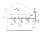
一方、締結ユニット370は、スライダー371を移送する加圧部P2をさらに含むのがより好ましい。特に、加圧部P2は、図9または図10に示しているように、スライダー371に対して回転可能に移動軸MHを通じてスライダーの一端にその一端がヒンジ結合される連結バー375と、連結バーと所定の角度をなすように連結バーの他端に固定形成され、連結バーの他端とその接合部位が固定軸SHを通じてメインボディー310にヒンジ結合される間接移送レバー373とを含むのが好ましい。これによって、間接移送レバー373の加圧時に、固定軸SHを基準に連結バー375が回転しながら移動軸MH及びスライダー371を移送する。また、加圧部P2は、組立解除時にスライダー371が外部に離脱するのを防止するとともに、締結後にスライダーが外部の振動によって移動するのを防止する役割も果たす。
On the other hand, it is more preferable that the
間接移送レバー373の加圧方向は、ジャンクションボックスの周囲部品との干渉を避けるために、メインボディー310を基準に上/下のいずれか一方向であり、移動軸MH及びスライダー371の移送方向は、メインボディー310を基準に左/右のいずれか一方向であるのがより好ましい。一方、スライダー371の一端には、移動軸MHが挿入される挿入スロット374が形成され、挿入スロットは、移動軸が設定された範囲内で移動できるように延長形成されるのが好ましい。言い換えれば、挿入スロット374を延長形成する理由は、固定軸SHを中心にした移動軸MHの円弧運動に対してスライダー371の直線運動が妨害されないようにするためである。
The pressure direction of the
図10乃至図12を参照して、第2実施例によるジャンクションボックスアセンブリーの締結過程を説明する。説明に先立って、ソケット311は、メインボディー310に一体形成することもでき、別途に形成することもできる。したがって、以下では、メインボディーのソケット311及び下部カバーのコネクタ351を組立てる過程を中心を説明する。第一に、図10に示す通り、ソケット311及びコネクタ351を互いに対応するように位置させる。そして、矢印方向にソケット311を移動させる。なお、ソケット311及びコネクタ351を互いに対応するように位置させなくても、ソケット311を左/右に移動させれば、スライダー371に形成された流入溝372bにコネクタの案内突起351aが自動的に挿入される。
A process of fastening the junction box assembly according to the second embodiment will be described with reference to FIGS. Prior to the description, the
第二に、図11に示す通り、コネクタの案内突起351aがスライダーの流入溝372bを通じて傾斜スロット372aに安着するようになる。そして、矢印方向に間接移送レバー373を加圧する。第三に、図11及び12に示すように、間接移送レバー373を矢印方向に加圧すれば、これに固定された連結バー375が固定軸SHを中心に回転しながらスライダー371を矢印方向に移動させるようになる。これと同時に、コネクタ351に形成された案内突起351aは、傾斜スロット372aに沿って引続き移動する。これと同時に、コネクタ351は、図面の上方向に移動しながら、最終的にソケット311に締結される。
Secondly, as shown in FIG. 11, the
一方、案内突起351a及びこれに対応する突起流動部372は互いに噛合う構造であるので、図示していないが、その形成位置が互いに変わっても良い。例えば、第2実施例では、案内突起351aが下部カバーのコネクタ351に形成され、突起流動部372がスライダー371に形成されるとしたが、互いにその形成位置を変えて、案内突起がスライダーに形成され、突起流動部が下部カバーのコネクタに形成されても差支えない。
On the other hand, since the protruding
以下、第2実施例の変形例によるジャンクションボックスアセンブリーを説明する。図13は第2実施例の変形例によるジャンクションボックスアセンブリーの要部を示した概略図である。第2実施例の変形例によるジャンクションボックスアセンブリーは、図13に示すように、スライダー471の装着位置及び間接移送レバー473及び案内突起411aの形成位置が異なるだけで、第2実施例と同一である。したがって、以下では、スライダー471の装着位置及び間接移送レバー473及び案内突起411aの形成位置を中心に説明する。
Hereinafter , a junction box assembly according to a modification of the second embodiment will be described. FIG. 13 is a schematic view showing a main part of a junction box assembly according to a modification of the second embodiment . As shown in FIG. 13, the junction box assembly according to the modification of the second embodiment is the same as the second embodiment except that the mounting position of the
まず、スライダー471は、下部カバー450に形成される。具体的に、下部カバーのコネクタ451にスライディング可能に形成されるのが好ましい。そして、案内突起411aは、スライダー471の突起流動部472に対応するようにメインボディー410に形成される。具体的に、メインボディーのソケット411に形成されるのが好ましい。また、間接移送レバー473は、固定軸SHの装着位置を除いて第2実施例と同一で、特に固定軸SHは、下部カバー450から延長されたブラケット452に固定されるのが好ましい。一方、具体的な構成及び締結過程は第2実施例から十分に理解可能なので、その詳しい説明は省略する。
First, the
以上、本発明に関する好ましい実施例を説明したが、本発明は実施例に限定されず、本発明の属する技術範囲を逸脱しない範囲での全ての変更が含まれる。 On more than has been described preferred embodiments relating to the present invention, the present invention is not limited to real施例includes all modifications without departing from the scope of this invention belongs.
10、110、210、310、410 メインボディー
111、211、311、411 ソケット
112、212、372、472 突起流動部
112a、372a 傾斜スロット
112b、372b 流入溝
30、130、330 第1カバー(上部カバー)
50、150、250、350、450 第2カバー(下部カバー)
51、151、251、351、451 コネクタ
151a レール
151b 係止突起
151c ロック突起
170、370 締結ユニット
171、271、371、471 スライダー
171a、171b、371a、371b 分岐
171c、271c、351a、411a 案内突起
172 直接移送レバー
173 離脱防止突起
373、473 間接移送レバー
374 挿入スロット
375 連結バー
452 ブラケット
R 離脱防止部
P1、P2 加圧部
SH 固定軸
MH 移動軸
L ロック部
10, 110 , 210 , 310 , 410
30, 130 , 330 First cover (upper cover)
50, 150 , 250 , 350 , 450 Second cover (lower cover)
51, 151 , 251 , 351 , 451
Claims (6)
このメインボディーの前記電気回路が安着した一面を覆う第1カバーと、
前記メインボディーの一面に対向する他面を覆い、前記一つ以上のソケットと対応するコネクタを有する第2カバーと、
この第2カバーにスライディング可能に形成されるスライダーと、このスライダーの一側に形成される一つ以上の案内突起と、この案内突起に対応するように前記メインボディーに形成され、前記スライダーが移動する時に前記案内突起の移動方向に対して垂直移動するように所定の角度に傾いた傾斜スロットを有する突起流動部と、前記スライダーを移送する加圧部と、を備え、そのスライディング運動に対応して前記ソケット及び前記コネクタが互いに結合されるように前記メインボディー及び前記第2カバーを締結する締結ユニットと、を含んでなるジャンクションボックスアセンブリーであって、
前記加圧部は、
前記スライダーに対して回転可能に移動軸を通じて前記スライダーの一端にその一端がヒンジ結合される連結バーと、
前記連結バーと所定の角度をなすように前記連結バーの他端に固定形成され、前記連結バーの他端とその接合部位が固定軸を通じて前記メインボディーにヒンジ結合される間接移送レバーと、を含み、
前記間接移送レバーの加圧時に、前記固定軸を基準に前記連結バーが回転しながら前記移動軸及びスライダーを移送することを特徴とするジャンクションボックスアセンブリー。 Electric circuit is seated, a main body having one or more sockets that are electrically connected to the electrical circuit,
A first cover covering the surface of the main body on which the electric circuit is seated ;
A second cover having a connector corresponding to the one or more sockets, covering the other surface facing the one surface of the main body ;
A slider formed on the second cover so as to be slidable, one or more guide protrusions formed on one side of the slider, and formed on the main body so as to correspond to the guide protrusions, the slider moving A protrusion flow part having an inclined slot inclined at a predetermined angle so as to move vertically with respect to the moving direction of the guide protrusion, and a pressurizing part for transferring the slider, corresponding to the sliding movement. And a fastening unit for fastening the main body and the second cover so that the socket and the connector are coupled to each other, and a junction box assembly comprising:
The pressurizing part is
A connecting bar whose one end is hinged to one end of the slider through a moving shaft rotatably with respect to the slider;
An indirect transfer lever which is fixedly formed at the other end of the connecting bar so as to form a predetermined angle with the connecting bar, and the other end of the connecting bar and a joint portion thereof are hinged to the main body through a fixed shaft; Including
A junction box assembly that transfers the moving shaft and the slider while the connecting bar rotates with respect to the fixed shaft when the indirect transfer lever is pressurized .
このメインボディーの前記電気回路が安着した一面を覆う第1カバーと、
前記メインボディーの一面に対向する他面を覆い、前記一つ以上のソケットと対応するコネクタを有する第2カバーと、
前記メインボディーにスライディング可能に形成されるスライダーと、このスライダーの一側に形成される一つ以上の案内突起と、この案内突起に対応するように前記第2カバーに形成され、前記スライダーが移動する時に前記案内突起の移動方向に対して垂直移動するように所定の角度に傾いた傾斜スロットを有する突起流動部と、前記スライダーを移送する加圧部と、を備え、そのスライディング運動に対応して前記ソケット及び前記コネクタが互いに結合されるように前記メインボディー及び前記第2カバーを締結する締結ユニットと、を含んでなるジャンクションボックスアセンブリーであって、
前記加圧部は、
前記スライダーに対して回転可能に移動軸を通じて前記スライダーの一端にその一端がヒンジ結合される連結バーと、
この連結バーと所定の角度をなすように前記連結バーの他端に固定形成され、前記連結バーの他端とその接合部位が固定軸を通じて前記メインボディーにヒンジ結合される間接移送レバーと、を含み、
前記間接移送レバーの加圧時に、前記固定軸を基準に前記連結バーが回転しながら前記移動軸及びスライダーを移送することを特徴とするジャンクションボックスアセンブリー。 A main body having one or more sockets on which the electrical circuit is seated and electrically connected to the electrical circuit;
A first cover covering the surface of the main body on which the electric circuit is seated;
A second cover having a connector corresponding to the one or more sockets, covering the other surface facing the one surface of the main body;
A slider formed to be slidable on the main body, one or more guide protrusions formed on one side of the slider, and formed on the second cover so as to correspond to the guide protrusions, the slider moving A protrusion flow part having an inclined slot inclined at a predetermined angle so as to move vertically with respect to the moving direction of the guide protrusion, and a pressurizing part for transferring the slider, corresponding to the sliding movement. And a fastening unit for fastening the main body and the second cover so that the socket and the connector are coupled to each other, and a junction box assembly comprising:
The pressurizing part is
A connecting bar whose one end is hinged to one end of the slider through a moving shaft rotatably with respect to the slider;
An indirect transfer lever which is fixedly formed at the other end of the connecting bar so as to form a predetermined angle with the connecting bar, and the other end of the connecting bar and a joint portion thereof are hinged to the main body through a fixed shaft; Including
A junction box assembly that transfers the moving shaft and the slider while the connecting bar rotates with respect to the fixed shaft when the indirect transfer lever is pressurized .
このメインボディーの前記電気回路が安着した一面を覆う第1カバーと、
前記メインボディーの一面に対向する他面を覆い、前記一つ以上のソケットと対応するコネクタを有する第2カバーと、
この第2カバーに形成される一つ以上の案内突起と、前記メインボディーにスライディング可能に形成され、前記案内突起に対応するように形成されるスライダーと、前記案内突起に対応するように前記スライダーに形成され、前記スライダーが移動する時に前記案内突起がその移動方向に対して垂直移動するように所定の角度に傾いた傾斜スロットを有する突起流動部と、前記スライダーを移送する加圧部と、を備え、そのスライディング運動に対応して前記ソケット及び前記コネクタが互いに結合されるように前記メインボディー及び前記第2カバーを締結する締結ユニットと、を含んでなるジャンクションボックスアセンブリーであって、
前記加圧部は、
前記スライダーに対して回転可能に移動軸を通じて前記スライダーの一端にその一端がヒンジ結合される連結バーと、
この連結バーと所定の角度をなすように前記連結バーの他端に固定形成され、前記連結バーの他端とその接合部位が固定軸を通じて前記メインボディーにヒンジ結合される間接移送レバーと、を含み、
前記間接移送レバーの加圧時に、前記固定軸を基準に前記連結バーが回転しながら前記移動軸及びスライダーを移送することを特徴とするジャンクションボックスアセンブリー。 A main body having one or more sockets on which the electrical circuit is seated and electrically connected to the electrical circuit;
A first cover covering the surface of the main body on which the electric circuit is seated;
A second cover having a connector corresponding to the one or more sockets, covering the other surface facing the one surface of the main body;
One or more guide protrusions formed on the second cover, a slider formed to be slidable on the main body, and formed to correspond to the guide protrusions, and the slider to correspond to the guide protrusions A protrusion flow part having an inclined slot inclined at a predetermined angle so that the guide protrusion moves perpendicularly to the moving direction when the slider moves, and a pressure part for transferring the slider, And a fastening unit that fastens the main body and the second cover so that the socket and the connector are coupled to each other in response to the sliding movement.
The pressurizing part is
A connecting bar whose one end is hinged to one end of the slider through a moving shaft rotatably with respect to the slider;
An indirect transfer lever which is fixedly formed at the other end of the connecting bar so as to form a predetermined angle with the connecting bar, and the other end of the connecting bar and a joint portion thereof are hinged to the main body through a fixed shaft; Including
A junction box assembly that transfers the moving shaft and the slider while the connecting bar rotates with respect to the fixed shaft when the indirect transfer lever is pressurized .
このメインボディーの前記電気回路が安着した一面を覆う第1カバーと、
前記メインボディーの一面に対向する他面を覆い、前記一つ以上のソケットと対応するコネクタを有する第2カバーと、
前記メインボディーに形成される一つ以上の案内突起と、前記第2カバーにスライディング可能に形成され、前記案内突起に対応するように形成されるスライダーと、前記案内突起に対応するように前記スライダーに形成され、前記スライダーが移動する時に前記案内突起がその移動方向に対して垂直移動するように所定の角度に傾いた傾斜スロットを有する突起流動部と、前記スライダーを移送する加圧部と、を備え、そのスライディング運動に対応して前記ソケット及び前記コネクタが互いに結合されるように前記メインボディー及び前記第2カバーを締結する締結ユニットと、を含んでなるジャンクションボックスアセンブリーであって、
前記加圧部は、
前記スライダーに対して回転可能に移動軸を通じて前記スライダーの一端にその一端がヒンジ結合される連結バーと、
この連結バーと所定の角度をなすように前記連結バーの他端に固定形成され、前記連結バーの他端とその接合部位が固定軸を通じて前記第2カバーにヒンジ結合される間接移送レバーと、を含み、
この間接移送レバーの加圧時に、前記固定軸を基準に前記連結バーが回転しながら前記移動軸及びスライダーを移送することを特徴とするジャンクションボックスアセンブリー。 A main body having one or more sockets on which the electrical circuit is seated and electrically connected to the electrical circuit;
A first cover covering the surface of the main body on which the electric circuit is seated;
A second cover having a connector corresponding to the one or more sockets, covering the other surface facing the one surface of the main body;
One or more guide protrusions formed on the main body, a slider formed to be slidable on the second cover and formed to correspond to the guide protrusions, and the slider to correspond to the guide protrusions A protrusion flow part having an inclined slot inclined at a predetermined angle so that the guide protrusion moves perpendicularly to the moving direction when the slider moves, and a pressure part for transferring the slider, And a fastening unit that fastens the main body and the second cover so that the socket and the connector are coupled to each other in response to the sliding movement.
The pressurizing part is
A connecting bar whose one end is hinged to one end of the slider through a moving shaft rotatably with respect to the slider;
An indirect transfer lever that is fixedly formed at the other end of the connection bar so as to form a predetermined angle with the connection bar, and the other end of the connection bar and its joint portion are hinged to the second cover through a fixed shaft; Including
A junction box assembly that transfers the moving shaft and the slider while the connecting bar rotates with respect to the fixed shaft when the indirect transfer lever is pressed .
前記移動軸及び前記スライダーの移送方向は、前記加圧方向に応じて前記メインボディーを基準に左/右のいずれか一方向であることを特徴とする請求項1乃至4のいずれかに記載のジャンクションボックスアセンブリー。 The direction of pressurization of the indirect transfer lever is one of up / down with respect to the main body,
The transfer direction of the moving shaft and the slider according to any one of claims 1 to 4, wherein the is one direction of left / right relative to the main body in accordance with the pressure direction Junction box assembly.
Applications Claiming Priority (2)
| Application Number | Priority Date | Filing Date | Title |
|---|---|---|---|
| KR20030086630 | 2003-12-02 | ||
| KR1020040035157A KR100623645B1 (en) | 2003-12-02 | 2004-05-18 | Junction box assembly |
Publications (2)
| Publication Number | Publication Date |
|---|---|
| JP2005168290A JP2005168290A (en) | 2005-06-23 |
| JP4418355B2 true JP4418355B2 (en) | 2010-02-17 |
Family
ID=36584581
Family Applications (1)
| Application Number | Title | Priority Date | Filing Date |
|---|---|---|---|
| JP2004343228A Expired - Fee Related JP4418355B2 (en) | 2003-12-02 | 2004-11-29 | Junction box assembly |
Country Status (4)
| Country | Link |
|---|---|
| US (2) | US20050118844A1 (en) |
| JP (1) | JP4418355B2 (en) |
| CN (1) | CN100452591C (en) |
| DE (1) | DE102004058242A1 (en) |
Families Citing this family (13)
| Publication number | Priority date | Publication date | Assignee | Title |
|---|---|---|---|---|
| KR101259535B1 (en) * | 2006-09-27 | 2013-05-06 | 타이코에이엠피(유) | a connector |
| US7459630B2 (en) * | 2006-10-05 | 2008-12-02 | Lear Corporation | Junction box assembly |
| JP2009260024A (en) * | 2008-04-16 | 2009-11-05 | Toyota Industries Corp | Housing of electronic apparatus |
| US8047860B2 (en) * | 2008-08-13 | 2011-11-01 | Delphi Technologies, Inc. | Connector engage mechanism |
| JP5187245B2 (en) * | 2009-03-16 | 2013-04-24 | 住友電装株式会社 | Electrical junction box |
| DE202010003411U1 (en) * | 2010-03-10 | 2011-08-04 | Kiekert Ag | Motor vehicle component housing |
| KR101143871B1 (en) | 2010-04-12 | 2012-05-09 | 영화테크(주) | Connector member for junction box of vehicle |
| JP5828290B2 (en) * | 2012-02-27 | 2015-12-02 | 株式会社オートネットワーク技術研究所 | Electrical junction box |
| KR101360103B1 (en) | 2012-07-06 | 2014-02-12 | 영화테크(주) | Junction Box Having Detachable Mounting Bracket |
| DE102013211976B4 (en) * | 2013-06-25 | 2024-06-27 | Zf Friedrichshafen Ag | Press-in device for a connector module of a circuit board for a control unit of a vehicle transmission |
| CN105529662B (en) * | 2016-02-05 | 2017-12-01 | 沈阳莹和科技有限公司 | Junction box assembly structure |
| CN113067293A (en) * | 2020-12-30 | 2021-07-02 | 田志勇 | Electrical junction box |
| CN113324021B (en) * | 2021-05-17 | 2024-06-07 | 江苏泰隆减速机股份有限公司 | Emergent applicable speed reducer of modularization |
Family Cites Families (28)
| Publication number | Priority date | Publication date | Assignee | Title |
|---|---|---|---|---|
| US4586771A (en) * | 1985-03-04 | 1986-05-06 | Amp Incorporated | Connector assembly having camming system for mating and unmating |
| JPH07120541B2 (en) * | 1990-11-30 | 1995-12-20 | 矢崎総業株式会社 | Connector with cam member for mating operation |
| GB9214525D0 (en) * | 1992-07-08 | 1992-08-19 | Amp Gmbh | Electrical connector with improved retaining latch |
| CN2137400Y (en) * | 1992-11-06 | 1993-06-30 | 黄丽姬 | Connection box |
| FR2705503B1 (en) * | 1993-05-21 | 1995-07-28 | Francelco Sa | Electrical connector with insertion and extraction drawer. |
| US5876226A (en) * | 1994-10-14 | 1999-03-02 | The Whitaker Corporation | Connector with cam member |
| FR2730585B1 (en) * | 1995-02-10 | 1997-04-25 | Framatome Connectors Int | ELECTRICAL CONNECTOR WITH CONTACT LOCKING GRID AND DRAWER |
| DE19509094A1 (en) * | 1995-03-16 | 1996-09-26 | Boehringer Mannheim Gmbh | Quantitative transmission spectroscopy using sample carriers with networks |
| US6361362B1 (en) * | 1995-08-22 | 2002-03-26 | The Whitaker Corporation | Arrangement with two half-plugs for securing in a wall |
| DE19530844B4 (en) * | 1995-08-22 | 2005-10-13 | The Whitaker Corp., Wilmington | Electrical connector with actuating slide |
| JP3384536B2 (en) * | 1996-09-03 | 2003-03-10 | 矢崎総業株式会社 | Low insertion force connector |
| JP3087667B2 (en) * | 1996-11-25 | 2000-09-11 | 住友電装株式会社 | Electrical junction box for car |
| JP3467373B2 (en) * | 1997-03-12 | 2003-11-17 | 矢崎総業株式会社 | Connector mating structure |
| JPH1126069A (en) * | 1997-06-27 | 1999-01-29 | Yazaki Corp | Slide-fitting type connector |
| US6142826A (en) * | 1998-03-13 | 2000-11-07 | The Whitaker Corporation | Sealed electrical connector with secondary locking member |
| JP3568774B2 (en) * | 1998-04-20 | 2004-09-22 | 矢崎総業株式会社 | Connector connection structure |
| US6155850A (en) * | 1998-09-25 | 2000-12-05 | The Whitaker Corporation | Cam slide electrical connector |
| US6254407B1 (en) * | 1999-02-17 | 2001-07-03 | Framatome Connectors Interlock, Inc. | Mechanical assist cam slide device |
| JP3675242B2 (en) * | 1999-08-04 | 2005-07-27 | 矢崎総業株式会社 | Low insertion force connector |
| ES1044100Y (en) * | 1999-08-06 | 2000-08-16 | Mecanismos Aux Ind | ANCHORAGE SYSTEM FOR CONNECTOR BOX IN SERVICE BOXES. |
| EP1100160B1 (en) * | 1999-11-10 | 2007-03-21 | Molex Incorporated | Electrical connector assembly with improved camming system |
| US6305957B1 (en) * | 2000-02-24 | 2001-10-23 | Delphi Technologies, Inc. | Electrical connector assembly |
| US6475004B2 (en) * | 2001-01-09 | 2002-11-05 | Tyco Electronics Corporation | Connector assembly with an engagement assist member and connector position assurance device |
| US6361336B1 (en) * | 2001-02-16 | 2002-03-26 | Alcoa Fujikura Limited | Electrical coupling device for aligning and interengaging a plurality of multi-pin connectors |
| JP2002315149A (en) * | 2001-04-12 | 2002-10-25 | Yazaki Corp | Electrical junction box |
| JP2003331983A (en) * | 2002-05-14 | 2003-11-21 | Sumitomo Wiring Syst Ltd | Lever connector |
| JP2004020236A (en) * | 2002-06-12 | 2004-01-22 | Advantest Corp | Connector, semiconductor part installation system, and testing equipment |
| JP3926223B2 (en) * | 2002-06-28 | 2007-06-06 | 株式会社オートネットワーク技術研究所 | Breaker device |
-
2004
- 2004-11-29 JP JP2004343228A patent/JP4418355B2/en not_active Expired - Fee Related
- 2004-11-29 US US10/998,522 patent/US20050118844A1/en not_active Abandoned
- 2004-12-01 CN CNB2004100912704A patent/CN100452591C/en not_active Expired - Fee Related
- 2004-12-02 DE DE102004058242A patent/DE102004058242A1/en not_active Ceased
-
2006
- 2006-02-03 US US11/346,939 patent/US7125263B2/en active Active
Also Published As
| Publication number | Publication date |
|---|---|
| DE102004058242A1 (en) | 2005-07-14 |
| US20060128182A1 (en) | 2006-06-15 |
| CN1625002A (en) | 2005-06-08 |
| JP2005168290A (en) | 2005-06-23 |
| CN100452591C (en) | 2009-01-14 |
| US7125263B2 (en) | 2006-10-24 |
| US20050118844A1 (en) | 2005-06-02 |
Similar Documents
| Publication | Publication Date | Title |
|---|---|---|
| JP4418355B2 (en) | Junction box assembly | |
| CN206154306U (en) | Robot system and casing spare that is used for this kind of robot system | |
| US5691878A (en) | Snap-lockable housing for fluorescent lamp ballasts | |
| US5639113A (en) | Mounting assembly for air bag | |
| JP7489182B2 (en) | Easy Lock P-clamp | |
| TW200808594A (en) | Device for attaching a windscreen-wiper blade to an arm | |
| AU2005222253A1 (en) | Connector for connecting electrical wires | |
| CN100537312C (en) | Windshield wiper, especially for a motor vehicle | |
| US8091198B2 (en) | Reconfigurable pallet | |
| JP3234780U (en) | Connector with lock and unlock structure | |
| US7345891B2 (en) | Circuit board assembly | |
| CN101369756B (en) | Motor fixing structure and motor assembly | |
| JPH089917Y2 (en) | Connector fixing structure | |
| WO2016005413A1 (en) | An integrated bracket for automotive heat exchanger | |
| KR100623645B1 (en) | Junction box assembly | |
| CN200942808Y (en) | Automobile deflector and locating device therefor | |
| KR101514888B1 (en) | A bracket for absorbing tolerance | |
| KR200431337Y1 (en) | Junction box for vehicle | |
| JP4962236B2 (en) | Lever connection structure | |
| JP2709352B2 (en) | Connection method between valve shaft and actuator drive shaft | |
| WO2020110220A1 (en) | Attachment fixture and control unit | |
| JPH10108337A (en) | Mounting structure of electric connection box | |
| JP4521069B2 (en) | Rod connector | |
| JP3571868B2 (en) | Movable mounting device | |
| JP3923269B2 (en) | Electrical junction box connection structure |
Legal Events
| Date | Code | Title | Description |
|---|---|---|---|
| A621 | Written request for application examination |
Free format text: JAPANESE INTERMEDIATE CODE: A621 Effective date: 20071120 |
|
| A131 | Notification of reasons for refusal |
Free format text: JAPANESE INTERMEDIATE CODE: A131 Effective date: 20090721 |
|
| A521 | Request for written amendment filed |
Free format text: JAPANESE INTERMEDIATE CODE: A523 Effective date: 20091021 |
|
| TRDD | Decision of grant or rejection written | ||
| A01 | Written decision to grant a patent or to grant a registration (utility model) |
Free format text: JAPANESE INTERMEDIATE CODE: A01 Effective date: 20091117 |
|
| A01 | Written decision to grant a patent or to grant a registration (utility model) |
Free format text: JAPANESE INTERMEDIATE CODE: A01 |
|
| A61 | First payment of annual fees (during grant procedure) |
Free format text: JAPANESE INTERMEDIATE CODE: A61 Effective date: 20091127 |
|
| R150 | Certificate of patent or registration of utility model |
Ref document number: 4418355 Country of ref document: JP Free format text: JAPANESE INTERMEDIATE CODE: R150 Free format text: JAPANESE INTERMEDIATE CODE: R150 |
|
| FPAY | Renewal fee payment (event date is renewal date of database) |
Free format text: PAYMENT UNTIL: 20121204 Year of fee payment: 3 |
|
| FPAY | Renewal fee payment (event date is renewal date of database) |
Free format text: PAYMENT UNTIL: 20121204 Year of fee payment: 3 |
|
| FPAY | Renewal fee payment (event date is renewal date of database) |
Free format text: PAYMENT UNTIL: 20131204 Year of fee payment: 4 |
|
| R250 | Receipt of annual fees |
Free format text: JAPANESE INTERMEDIATE CODE: R250 |
|
| R250 | Receipt of annual fees |
Free format text: JAPANESE INTERMEDIATE CODE: R250 |
|
| R250 | Receipt of annual fees |
Free format text: JAPANESE INTERMEDIATE CODE: R250 |
|
| R250 | Receipt of annual fees |
Free format text: JAPANESE INTERMEDIATE CODE: R250 |
|
| R250 | Receipt of annual fees |
Free format text: JAPANESE INTERMEDIATE CODE: R250 |
|
| R250 | Receipt of annual fees |
Free format text: JAPANESE INTERMEDIATE CODE: R250 |
|
| R250 | Receipt of annual fees |
Free format text: JAPANESE INTERMEDIATE CODE: R250 |
|
| LAPS | Cancellation because of no payment of annual fees |