JP4417758B2 - Vacuum cleaner - Google Patents

Vacuum cleaner Download PDF

Info

Publication number
JP4417758B2
JP4417758B2 JP2004104803A JP2004104803A JP4417758B2 JP 4417758 B2 JP4417758 B2 JP 4417758B2 JP 2004104803 A JP2004104803 A JP 2004104803A JP 2004104803 A JP2004104803 A JP 2004104803A JP 4417758 B2 JP4417758 B2 JP 4417758B2
Authority
JP
Japan
Prior art keywords
extension pipe
mouthpiece
floor
pin
suction
Prior art date
Legal status (The legal status is an assumption and is not a legal conclusion. Google has not performed a legal analysis and makes no representation as to the accuracy of the status listed.)
Expired - Lifetime
Application number
JP2004104803A
Other languages
Japanese (ja)
Other versions
JP2005287659A5 (en
JP2005287659A (en
Inventor
昌平 佐藤
高徳 西山
功一 梅澤
亘 山本
泰治 田島
Current Assignee (The listed assignees may be inaccurate. Google has not performed a legal analysis and makes no representation or warranty as to the accuracy of the list.)
Hitachi Appliances Inc
Original Assignee
Hitachi Appliances Inc
Priority date (The priority date is an assumption and is not a legal conclusion. Google has not performed a legal analysis and makes no representation as to the accuracy of the date listed.)
Filing date
Publication date
Application filed by Hitachi Appliances Inc filed Critical Hitachi Appliances Inc
Priority to JP2004104803A priority Critical patent/JP4417758B2/en
Publication of JP2005287659A publication Critical patent/JP2005287659A/en
Publication of JP2005287659A5 publication Critical patent/JP2005287659A5/ja
Application granted granted Critical
Publication of JP4417758B2 publication Critical patent/JP4417758B2/en
Anticipated expiration legal-status Critical
Expired - Lifetime legal-status Critical Current

Links

Images

Description

本発明は、電気掃除機に係り、特に、延長管部と床用吸口体部との着脱を容易に行うことができるようにした電気掃除機に関する。   The present invention relates to a vacuum cleaner, and more particularly to a vacuum cleaner that can be easily attached to and detached from an extension pipe portion and a floor mouthpiece portion.

従来技術による電気掃除機は、ゴミを収集して格納する本体側のダストケースを有する掃除機本体と、掃除機本体に接続可能なホース部と、該ホース部に接続可能で内部に風路を形成したグリップ部と、該グリップ部に接続可能で風路を形成した延長管部と、該延長管部に接続可能な床用吸口体部とを備えて構成されるのが一般的である。そして、電気掃除機に関しては、このような基本構成を備えることを前提として種々の提案がなされている。例えば、この種の電気掃除機に関する従来技術として、例えば、特許文献1、2、3等に記載された技術がしられている。
特開2001−314354号公報 特開平11−187993号公報 特開平11−155786号公報
The vacuum cleaner according to the prior art includes a vacuum cleaner main body having a dust case on the main body side for collecting and storing dust, a hose portion connectable to the vacuum cleaner main body, a hose portion connectable to the hose portion, and an air passage inside. Generally, it is configured to include a formed grip portion, an extension pipe portion that is connectable to the grip portion and forms an air passage, and a floor mouthpiece portion that is connectable to the extension pipe portion. And regarding a vacuum cleaner, various proposals are made on the assumption that such a basic configuration is provided. For example, as a conventional technique related to this type of electric vacuum cleaner, for example, techniques described in Patent Documents 1, 2, 3, and the like are used.
JP 2001-314354 A JP-A-11-189933 JP-A-11-155786

前述した従来技術による電気掃除機は、床面の掃除の際には、前述した構成のまま不自由することなく使用することが可能なものである。そして、隙間等の狭い空間の掃除を行う場合、接続されている延長管部と床用吸口体部とを切り離して、延長管部の先端に隙間用吸口、ハケブラシ等のアタッチメントを接続して使用するのが一般的である。この延長管部と床用吸口体部とを切り離す作業あるいはその後の接続の作業は、利用者が延長管部と床用吸口体部とを手に持ったり、しゃがんだりして行わなければならないものである。すなわち、前述した従来技術による電気掃除機は、必ずしも最良と言える構造とは言い難かった。   The above-described conventional vacuum cleaner can be used without any inconvenience with the above-described configuration when cleaning the floor surface. And when cleaning a narrow space such as a gap, separate the connected extension pipe part and the floor suction body part, and connect an attachment such as a suction mouth for a gap and a brush brush to the tip of the extension pipe part. It is common to do. The work of separating the extension pipe part from the floor mouthpiece part or the subsequent connection work must be performed by the user holding the extension pipe part and the floor mouthpiece part in hand or squatting. It is. That is, the above-described conventional vacuum cleaner is not necessarily the best structure.

本発明の目的は、前述した従来技術の問題点を解決し、延長管部と吸口体部との着脱を容易に行うことができるようにした電気掃除機を提供することにある。 An object of the present invention is to provide an electric vacuum cleaner to be able to solve the problems of the prior art described above, facilitate the attachment and detachment of the extension pipe unit and the suction port body section.

本発明によれば前記目的は、吸口体部と延長管部とを備えた電気掃除機において、前記延長管部を前記吸口体部に装着したときに両者をロックさせ、前記吸口体部の被清掃面に対向する底面と前記延長管部とのなす角度が所定角度開いたときに、前記延長管部と前記吸口体部とを分離可能とするロック機構が、前記吸口体部と前記延長管部とにわたって設けられたことにより達成される。 According to the present invention, an object of the present invention is to provide a vacuum cleaner having a mouthpiece body portion and an extension pipe portion, wherein when the extension pipe portion is attached to the mouthpiece body portion, both are locked, and the mouthpiece body portion is covered. When the angle formed between the bottom surface facing the cleaning surface and the extension tube portion is opened by a predetermined angle, a lock mechanism that can separate the extension tube portion and the mouthpiece body portion includes the mouthpiece body portion and the extension tube. This is achieved by being provided over the part.

本発明によれば、吸口体の底面と延長管部とのなす角度が所定角度開いたとき、延長管部と吸口体部とが分離可能となるので、延長管部を引くだけで容易に延長管部を吸口体部から切り離すことができる。 According to the present invention, when the angle between the bottom surface and the extension pipe portion of the suction body is opened a predetermined angle, since the extension Nagakan unit and suction port body section becomes separable, only rather pull the extension Nagakan portion it can be separated easily extension pipe portion from suction port body section.

以下、本発明による電気掃除機の実施形態を図面により詳細に説明する。   Hereinafter, embodiments of a vacuum cleaner according to the present invention will be described in detail with reference to the drawings.

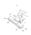
図1は本発明の一実施形態による電気掃除機の床用吸口体部、床用吸口体部に設けられた吸口継ぎ手部に接続された延長管部の部位の構成を説明する外観図である。図1において、101は床用吸口体部、102は下ケース、103は上ケース、104はバンパー、105はタイヤ、106はリンク、107はピンD、108はケーシングカバー、109はローラ、110はケーシング、111は足踏みペダル、112は吸口継ぎ手部、113は継ぎ手カバー、114は延長管部、115は延長管カバー、116はクランプ、117はクランプの突起部である。   FIG. 1 is an external view for explaining the structure of a portion of an extension pipe portion connected to a suction mouth portion provided on a floor suction body portion and a floor suction body portion of a vacuum cleaner according to an embodiment of the present invention. . In FIG. 1, 101 is a floor mouthpiece, 102 is a lower case, 103 is an upper case, 104 is a bumper, 105 is a tire, 106 is a link, 107 is a pin D, 108 is a casing cover, 109 is a roller, 110 is Casing, 111 is a foot pedal, 112 is a suction joint, 113 is a joint cover, 114 is an extension pipe, 115 is an extension pipe cover, 116 is a clamp, and 117 is a projection of the clamp.

本発明の一実施形態による電気掃除機の床用吸口体部101は、下ケース102、上ケース103、バンパー104を有し、その下面に床面の移動をスムーズにするためのタイヤ105、ローラ109が設けられて構成されている。そして、床用吸口体部101の長手方向の中央部には、リンク106、ピンD107を介して吸口継ぎ手部112が前後方向、すなわち、床用吸口体部101の長手方向に直角な方向に回道可能に取り付けられていると共に、後述で説明するように、吸口継ぎ手部112と延長管部114との接続を解除するための足踏みペダル111が設けられている。   A floor mouthpiece portion 101 of a vacuum cleaner according to an embodiment of the present invention has a lower case 102, an upper case 103, and a bumper 104, and a tire 105 and rollers for smooth movement of the floor surface on the lower surface thereof. 109 is provided. Then, at the center portion of the floor suction body portion 101 in the longitudinal direction, the suction joint portion 112 is rotated in the front-rear direction, that is, in the direction perpendicular to the longitudinal direction of the floor suction body portion 101 via the link 106 and the pin D107. A foot pedal 111 for releasing the connection between the suction joint portion 112 and the extension pipe portion 114 is provided, as will be described later.

床用吸口体部101と吸口継ぎ手部112との取り付け部分には、ケーシング110が設けられると共に、これをカバーするケーシングカバー108が設けられている。また、吸口継ぎ手部112の延長管部114との結合位置には、図2により後述する延長管部114とを接続を保持するクランプ機構が設けられており、この部分を覆う継ぎ手カバー113が設けられている。さらに、延長管部114の吸口継ぎ手部112との結合位置には、図2により後述する延長管部114とを接続を保持するクランプ機構の一部が吸口継ぎ手部112から延びて設けられており、この部分を覆う延長管かバー115が設けられており、延長管カバー115の穴からクランプ116の突起部117が露出している。   A casing 110 is provided at a portion where the floor suction body portion 101 and the suction joint portion 112 are attached, and a casing cover 108 for covering the casing 110 is provided. In addition, a clamping mechanism for holding a connection with the extension pipe portion 114 described later with reference to FIG. 2 is provided at a coupling position of the suction joint portion 112 with the extension pipe portion 114, and a joint cover 113 is provided to cover this portion. It has been. Further, a part of the clamp mechanism that holds the connection with the extension pipe portion 114, which will be described later with reference to FIG. 2, extends from the suction joint portion 112 at the coupling position of the extension pipe portion 114 with the mouthpiece joint portion 112. An extension tube or bar 115 is provided to cover this portion, and the protrusion 117 of the clamp 116 is exposed from the hole of the extension tube cover 115.

前述したように構成される床用吸口体部101、床用吸口体部101に設けられた吸口継ぎ手部112に接続された延長管部114において、延長管部114を床用吸口体部101から取り外したい場合、すなわち、利用者が延長管部114の先端に他のアタッチメント等を接続して使用したい場合、利用者は、床用吸口体部101の底面を床面に置いた状態で延長管部114を前後方向に回転させて、延長管部114をほぼ床面に垂直な状態にする。   In the floor mouthpiece portion 101 configured as described above, and the extension pipe portion 114 connected to the mouthpiece joint portion 112 provided in the floor mouthpiece body portion 101, the extension pipe portion 114 is connected to the floor mouthpiece body portion 101. When the user wants to remove it, that is, when the user wants to use another attachment or the like connected to the tip of the extension pipe part 114, the user extends the extension pipe with the bottom surface of the floor mouthpiece part 101 placed on the floor surface. The part 114 is rotated in the front-rear direction so that the extension pipe part 114 is substantially perpendicular to the floor surface.

本発明の実施形態は、後述するように、この状態で、自動的に吸口継ぎ手部112と延長管部114とを結合しているクランプ機構を解除する機構を吸口継ぎ手部112の床用吸口体部101との結合部に備えている。この結果、利用者は、延長管部114をほぼ床面に垂直な状態とした後に、延長管部114を上方に持ち上げることにより、容易に延長管部114を床用吸口体部101から取り外すことができる。   The embodiment of the present invention, as will be described later, in this state, a mechanism for automatically releasing the clamp mechanism that joins the suction joint part 112 and the extension pipe part 114 is a mouthpiece for the floor of the suction joint part 112. It is provided in a joint part with the part 101. As a result, the user can easily remove the extension pipe part 114 from the floor mouthpiece 101 by lifting the extension pipe part 114 upward after making the extension pipe part 114 substantially perpendicular to the floor surface. Can do.

一方、本発明の他の実施形態は、前述したような自動的にクランプ機構を解除する機構を設けずに、その代わりに、足踏みペダル111を床用吸口体部101に設けておき、この足踏みペダル111を利用者が足先等で踏み下した場合に前述のクランプ機構を解除するように構成することもできる。このようにした場合、利用者は、延長管部114をほぼ床面に垂直な状態とした後に、足踏みペダル111を踏んだ状態で、延長管部114を上方に持ち上げることにより、容易に延長管部114を床用吸口体部101から取り外すことができる。しかし、利用者が、延長管部114を取り外す意志がない場合、例えば、収納の際等に、延長管部114をほぼ床面に垂直な状態として、延長管部114を上方に持ち上げるだけでは延長管部114を床用吸口体部101から取り外すことができないことになり、利用者の不用意な操作で延長管部114が床用吸口体部101から取り外されることを防止することができる。   On the other hand, the other embodiment of the present invention does not provide the mechanism for automatically releasing the clamping mechanism as described above, but instead provides the foot pedal 111 on the floor mouthpiece 101 so that the foot The above-described clamp mechanism can be released when the user steps on the pedal 111 with his / her foot. In such a case, the user can easily extend the extension pipe portion 114 by lifting the extension pipe portion 114 upward with the foot pedal 111 depressed after the extension pipe portion 114 is substantially perpendicular to the floor surface. The part 114 can be removed from the floor mouthpiece part 101. However, if the user does not intend to remove the extension pipe part 114, for example, when the user puts the extension pipe part 114 in a state of being almost perpendicular to the floor surface, the extension pipe part 114 is lifted upward. The pipe part 114 cannot be removed from the floor mouthpiece part 101, and the extension pipe part 114 can be prevented from being removed from the floor mouthpiece part 101 by a user's careless operation.

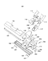
図2は図1により説明した床用吸口体部、床用吸口体部に設けられた吸口継ぎ手部に接続された延長管部の部位の内部構成を説明する分解斜視図である。図2において、201はタイヤシャフト、202はリンクシャフト、203は足踏みペダルシャフト、204は足踏みペダルバネ、205は流路カバー、206は回動カバー、207はピンDシャフト、208はピンF、209はピンFバネ、210はクランプバネであり、他の符号は図1の場合と同一である。   FIG. 2 is an exploded perspective view illustrating the internal structure of the portion of the extension pipe portion connected to the floor mouthpiece portion described in FIG. 1 and the mouthpiece joint portion provided in the floor mouthpiece portion. In FIG. 2, 201 is a tire shaft, 202 is a link shaft, 203 is a foot pedal shaft, 204 is a foot pedal spring, 205 is a flow path cover, 206 is a rotation cover, 207 is a pin D shaft, 208 is a pin F, and 209 are The pin F spring 210 is a clamp spring, and the other symbols are the same as in FIG.

床用吸口体部、床用吸口体部に設けられた吸口継ぎ手部に接続された延長管部の部位の全体は、図2に示しているような多数の部材により構成されているが、本発明の実施形態で特徴的な点は、リンク106が延長管部114の前後方向の回動に従ってピンD107が上下に移動するように構成されている点、及び、足踏みペダル111がリンクシャフト202、足踏みペダルシャフト203及び足踏みペダルバネ204により、リンク106に系合されて、足踏みペダル111が踏み降ろされたときに、リンク106を介してピンD107を押し上げるようにされている点である。そして、足踏みペダル111は、足踏みペダルバネ204により踏力がなくなったときに元に戻るようにされている。リンク106は、ピンDシャフト207によりピンD107を系合しており、また、スプリングバネ805を備えて回動カバー206と共に回動可能とされている。また、吸口継ぎ手部112は、ケーシング110に系合され、吸口継ぎ手部112及び延長管部114は、床用吸口体101に対して左右方向に回動可能とされている。   Although the whole part of the extension pipe part connected to the mouthpiece joint part provided in the floor mouthpiece part and the mouthpiece body part for floors is comprised by many members as shown in FIG. A characteristic point in the embodiment of the invention is that the link 106 is configured such that the pin D107 moves up and down as the extension pipe portion 114 rotates in the front-rear direction, and the foot pedal 111 includes the link shaft 202, The foot pedal shaft 203 and the foot pedal spring 204 are coupled to the link 106 so that when the foot pedal 111 is stepped down, the pin D107 is pushed up via the link 106. The foot pedal 111 returns to its original position when the foot pedal force is lost by the foot pedal spring 204. The link 106 is coupled with the pin D107 by a pin D shaft 207, and is provided with a spring spring 805 so as to be rotatable together with the rotation cover 206. Further, the inlet joint portion 112 is coupled to the casing 110, and the inlet joint portion 112 and the extension pipe portion 114 are rotatable in the left-right direction with respect to the floor mouthpiece 101.

前述において、延長管部114をほぼ垂直にした状態で、利用者により足踏みペダル111が踏み降ろされると、リンク106は、吸口継ぎ手部112の軸方向に沿って押し上げられ、吸口継ぎ手部112に設けられているピンF208の先端部をピンFバネ209に抗して押し上げるる。このピンF208の他端は、延長管114に設けられるクランプ116を構成する部材の端部に接して、クランプ116をクランプバネ210に抗して延長管部114の管中心方向に移動させる。この結果、後述するクランプ116の他端部704と延長管部114の壁面に設けたくぼみ部705との系合が外れ、延長管部114を床用吸口体部101から取り外すことが可能となる。   In the above description, when the foot pedal 111 is stepped down by the user with the extension pipe portion 114 substantially vertical, the link 106 is pushed up along the axial direction of the mouthpiece joint portion 112 and is provided in the mouthpiece joint portion 112. The tip of the pin F208 is pushed up against the pin F spring 209. The other end of the pin F <b> 208 is in contact with the end of a member constituting the clamp 116 provided in the extension pipe 114, and moves the clamp 116 toward the pipe center of the extension pipe 114 against the clamp spring 210. As a result, the other end portion 704 of the clamp 116, which will be described later, and the recessed portion 705 provided on the wall surface of the extension tube portion 114 are disconnected, and the extension tube portion 114 can be removed from the floor mouthpiece portion 101. .

また、延長管部114が垂直から離れた位置にある場合、リンク106が延長管部114の回動に伴って回動し、ピンD107の先端は、ピンF208の端部から離れた位置となり、足踏みペダル111が押し下げられた場合にも、ピンD107の先端がピンF208の端部を押すことがなく、後述するクランプ116の他端部704と延長管部114の壁面に設けたくぼみ部705が系合したままとなり、延長管部114を取り外すことができない。   Further, when the extension tube portion 114 is at a position away from the vertical, the link 106 is rotated with the rotation of the extension tube portion 114, and the tip of the pin D107 is positioned away from the end portion of the pin F208. Even when the foot pedal 111 is depressed, the tip of the pin D107 does not push the end of the pin F208, and the other end 704 of the clamp 116 and a recess 705 provided on the wall surface of the extension pipe 114 are described later. The extension pipe portion 114 cannot be removed.

前述では、足踏みペダル111を用いて延長管部114を取り外すことを可能にする構成について説明したが、ここに示す本発明の実施形態は、ピンD107の先端部までの長さを適宜大きく設定することにより、延長管部114をほぼ垂直にすると、前後方向の延長管部114の回動に伴って上下に移動するリンク106に系合しているピンD107の先端がピンF208の端部を押すようにすることができる。この場合、足踏みペダル111及びリンク106にリンクさせる機構を備える必要はないことになる。   In the above description, the configuration that enables the extension pipe portion 114 to be removed using the foot pedal 111 has been described. However, in the embodiment of the present invention shown here, the length to the tip portion of the pin D107 is set to be appropriately large. As a result, when the extension pipe part 114 is made substantially vertical, the tip of the pin D107 coupled to the link 106 that moves up and down with the rotation of the extension pipe part 114 in the front-rear direction pushes the end of the pin F208. Can be. In this case, it is not necessary to provide a mechanism for linking to the foot pedal 111 and the link 106.

なお、前述において、継ぎ手カバー113の内部側に設けられたピンF208、ピンFバネ209及びクランプピン117を有するクランプ116、クランプバネ210は、延長管部114と吸口継ぎ手部112とを接続してロックするクランプ機構を構成している。   In the above description, the pin F208, the pin F spring 209, the clamp 116 having the clamp pin 117, and the clamp spring 210 provided on the inner side of the joint cover 113 are connected to the extension pipe portion 114 and the suction joint portion 112. A clamping mechanism for locking is configured.

図3は本発明の一実施形態による電気掃除機の通常の使用状態の外観を示す図である。図3において、301は掃除機本体、302はホース部、303はグリップ部、304は手元スイッチであり、他の符号は図1の場合と同一である。   FIG. 3 is a view showing an external appearance of a vacuum cleaner according to an embodiment of the present invention in a normal use state. In FIG. 3, 301 is a cleaner body, 302 is a hose part, 303 is a grip part, 304 is a hand switch, and the other symbols are the same as those in FIG.

図3に示すように、本発明の一実施形態による電気掃除機全体は、内部に吸引気流を発生させて、発生した気流によりゴミを収集するモータ、ダストケースを有し、床面上の移動を容易にするための車輪を有する掃除機本体301と、掃除機本体301に接続可能なホース部302と、該ホース部302に接続可能で内部に風路を形成したグリップ部303と、該グリップ部に接続可能で風路を形成した延長管部114と、該延長管部に接続可能な吸口継ぎ手部112と、該吸口継ぎ手部112に接続された床用吸口体部101とを備えて構成される。グリップ部303には、手元操作用の各種のスイッチを有する手元スイッチ304が設けられており、掃除を行う場合、利用者は、グリップ部303を持ち、手元スイッチ304により、掃除機の起動、停止、吸い込み力の調整を行いながら、床用吸口体部101を移動させて掃除を行う。   As shown in FIG. 3, the entire vacuum cleaner according to an embodiment of the present invention has a motor and a dust case that generate a suction airflow and collects dust by the generated airflow, and move on the floor surface. A cleaner main body 301 having wheels for facilitating the cleaning, a hose portion 302 connectable to the cleaner main body 301, a grip portion 303 connectable to the hose portion 302 and having an air passage formed therein, and the grip An extension pipe part 114 that is connectable to the part and forms an air passage, a suction joint part 112 that can be connected to the extension pipe part, and a floor suction body part 101 connected to the suction joint part 112 Is done. The grip part 303 is provided with a hand switch 304 having various switches for hand operation. When cleaning is performed, the user holds the grip part 303, and the hand switch 304 is used to start and stop the cleaner. Then, while adjusting the suction force, the floor mouthpiece 101 is moved for cleaning.

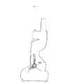
図4は本発明の一実施形態による電気掃除機の延長管部114を取り外すために、延長管部114をほぼ垂直に立てた状態を示す図、図5は延長管部114を取り外した状態を示す図である。   FIG. 4 is a view showing a state in which the extension pipe portion 114 is set up substantially vertically in order to remove the extension pipe portion 114 of the electric vacuum cleaner according to the embodiment of the present invention, and FIG. FIG.

利用者は、延長管部114を床用吸口体部101の吸口継ぎ手部112から取り外して、隙間用吸口、ハケブラシ等の他のアタッチメントを延長管部114に取り付けて使用したい場合、図4に示すように、延長管部114をほぼ垂直に立てて、足先等で足踏みペダル111を押し下げる操作を行い、延長管部114を上方に持ち上げることにより、図5に示すように、延長管部114を床用吸口体部101から取り外すことができる。後述するが、延長管部114を床用吸口体部101から取り外したとき、床用吸口体部101に取り付けられている吸口継ぎ手部112は、床面に置かれた床用吸口体部101から上方にほぼ垂直な角度を保持して自立できるように床用吸口体部101に取り付けられている。   FIG. 4 shows a case where the user removes the extension pipe part 114 from the inlet joint part 112 of the floor mouthpiece part 101 and attaches another attachment such as a gap suction mouth or a brush to the extension pipe part 114 for use. As shown in FIG. 5, the extension pipe portion 114 is made to stand substantially vertically as shown in FIG. 5 by performing the operation of pushing down the foot pedal 111 with the tip of the foot and lifting the extension pipe portion 114 upward. It can be removed from the floor mouthpiece 101. As will be described later, when the extension pipe portion 114 is removed from the floor mouthpiece portion 101, the mouthpiece joint portion 112 attached to the floor mouthpiece portion 101 is removed from the floor mouthpiece portion 101 placed on the floor surface. It is attached to the floor mouthpiece portion 101 so as to be able to stand independently while maintaining a substantially vertical angle upward.

図6は延長管部114を取り外して他のアタッチメントを延長管部114に取り付けた状態を示す図である。図6において、601は隙間用吸口、602はハケブラシである。   FIG. 6 is a view showing a state in which the extension pipe part 114 is removed and another attachment is attached to the extension pipe part 114. In FIG. 6, reference numeral 601 denotes a gap suction port, and 602 denotes a brush.

図6に示すように、延長管部114の先端部にアタッチメントとして隙間用吸口601を差し込めば、この隙間用吸口601を使用して狭い場所のゴミを掃除することができる。また、ハケブラシ602を延長管部114の先端部に取り付ければ、細かいゴミ等を寄せ集めながら掃除を行うことができる。このハケブラシ602は、アタッチメントとして利用者が延長管部114を取り外した後に取り付けるようにすることができるが、ハケブラシ602のブラシ部を延長管部114の周辺部に配置して取り付けておくことができる。このようにすると、延長管部114を床用吸口体部101の吸口継ぎ手部112に接続した状態では、ブラシ部が吸口継ぎ手部112の周囲を覆うようになるが、そのまま、床用吸口体部101を使用した掃除を行うことができ、延長管部114を取り外せば直ちに、ハケブラシ602を使用した掃除を行うことができる。さらに、隙間用吸口601を延長管部114の先端部に差し込んだ状態で、延長管部114を床用吸口体部101の吸口継ぎ手部112に接続して床用吸口体部101を使用することもできる。なお、ハケブラシ602を延長管部114の内側に配置することも可能である。   As shown in FIG. 6, when a gap suction port 601 is inserted as an attachment into the distal end portion of the extension pipe portion 114, dust in a narrow place can be cleaned using the gap suction port 601. Moreover, if the brush brush 602 is attached to the tip of the extension tube portion 114, cleaning can be performed while collecting fine dust and the like. The brush 602 can be attached as an attachment after the user removes the extension pipe part 114, but the brush part of the brush 602 can be arranged and attached to the peripheral part of the extension pipe part 114. . In this way, in a state where the extension pipe portion 114 is connected to the inlet joint portion 112 of the floor mouthpiece portion 101, the brush portion covers the periphery of the mouthpiece joint portion 112, but the floor mouthpiece portion is left as it is. The cleaning using the brush 101 can be performed immediately after the extension pipe portion 114 is removed. Further, with the gap suction port 601 inserted into the distal end of the extension pipe part 114, the extension pipe part 114 is connected to the suction joint part 112 of the floor suction body part 101 to use the floor suction body part 101. You can also. It is also possible to arrange the brush brush 602 inside the extension pipe portion 114.

図7は足踏みペダル111を用いて延長管部114を床用吸口体部101から取り外す機構を説明するための延長管部114を略水平状態とした場合を示す断面図、図8は足踏みペダル111を用いて延長管部114を床用吸口体部101から取り外す機構を説明するための延長管部114をほぼ垂直状態とした場合を示す断面図、図9は図8に示す状態で足踏みペダル111を押し下げた場合を示す断面図、図10は図9に示す状態から延長管部114を引き抜いて取り外した状態を示す断面図である。図7において、701はペダル回転中心、702は吸口継ぎ手部回転中心、703はクランプ回転中心であり、他の符号は図1、図2の場合と同一である。次に、これらの図面を参照して、足踏みペダル111を用いて延長管部114を床用吸口体部101から取り外す機構について説明する。なお、図面には、図7にのみ符号を示し、図8〜図10への符号の付与を省略した。また、図7には、説明を判り易くするために、通常の断面図にペダルを描き加えて示している。   FIG. 7 is a cross-sectional view showing a case where the extension pipe part 114 is in a substantially horizontal state for explaining a mechanism for removing the extension pipe part 114 from the floor mouthpiece part 101 using the foot pedal 111, and FIG. Sectional drawing which shows the case where the extension pipe part 114 for demonstrating the mechanism which removes the extension pipe part 114 from the floor suction body part 101 using FIG. 9 is made into a substantially perpendicular state, FIG. 9 shows the foot pedal 111 in the state shown in FIG. FIG. 10 is a cross-sectional view showing a state where the extension pipe portion 114 is pulled out and removed from the state shown in FIG. 9. In FIG. 7, reference numeral 701 denotes a pedal rotation center, 702 denotes a suction joint rotation center, 703 denotes a clamp rotation center, and the other reference numerals are the same as those in FIGS. Next, a mechanism for removing the extension pipe portion 114 from the floor mouthpiece portion 101 using the foot pedal 111 will be described with reference to these drawings. In the drawing, only the reference numeral is shown in FIG. 7, and the reference numerals in FIGS. 8 to 10 are omitted. Further, in FIG. 7, a pedal is added to a normal sectional view for easy understanding.

前述で説明したピンD107は、ケーシング110とケーシングカバー108との間に位置し、リンク106と系合して、リンク106の他端が足踏みペダル111とリンクシャフト202を介して連結されている。延長管部114を略水平な状態とした場合、吸口継ぎ手部112も略水平状態であり、図7に示すように、ピンD107とリンク106とはほぼ直角に系合しており、ピンD107は、その先端部も含めてケーシング110とケーシングカバー108との間に位置されている。そして、クランプ116の他端部704は、延長管114の壁面に設けたくぼみ部705に系合して、延長管114を吸口継ぎ手部112から取り外すことができないようにロックしている。この状態から延長管部114を垂直になるように回動させると、これに伴って、吸口継ぎ手部112は、吸口継ぎ手部回転中心702を支点として回動する事になり、図8に示すような状態となる。   The pin D 107 described above is located between the casing 110 and the casing cover 108, is coupled to the link 106, and the other end of the link 106 is connected to the foot pedal 111 and the link shaft 202. When the extension pipe portion 114 is in a substantially horizontal state, the inlet joint portion 112 is also in a substantially horizontal state, and as shown in FIG. 7, the pin D107 and the link 106 are engaged at a substantially right angle, and the pin D107 is In addition, it is positioned between the casing 110 and the casing cover 108 including its tip. The other end portion 704 of the clamp 116 is locked to the recess portion 705 provided on the wall surface of the extension tube 114 so that the extension tube 114 cannot be removed from the inlet joint portion 112. When the extension pipe part 114 is rotated vertically from this state, the suction joint part 112 is rotated with the suction joint part rotation center 702 as a fulcrum, as shown in FIG. It becomes a state.

図8に示す状態では、吸口継ぎ手部112の回動に伴って、ピンD107とリンク106とがほぼ直線状に系合した状態になり、ピンD107は、その先端部がケーシング110とケーシングカバー108との間から外部に出てピンF208の端部に対向する状態となる。この状態では、ピンD107がピンF208の端部を押す状態にはならず、このため、吸口継ぎ手部112と延長管部114とを接続してロックしているクランプ機構が解除されることはなく、延長管部114を引き抜いて取り外すことはできない。この状態で、利用者が足踏みペダル111を押し下げると、足踏みペダル111は、足踏みペダルシャフト203をペダル回転中心701として回転し、この結果、図9に示すような状態になる。   In the state shown in FIG. 8, the pin D107 and the link 106 are substantially linearly coupled with the rotation of the suction joint 112, and the tip of the pin D107 has a casing 110 and a casing cover 108. It will be in the state which goes outside from between and faces the end of the pin F208. In this state, the pin D107 does not press the end of the pin F208, and therefore, the clamping mechanism that connects and locks the suction joint portion 112 and the extension pipe portion 114 is not released. The extension pipe part 114 cannot be pulled out and removed. When the user depresses the foot pedal 111 in this state, the foot pedal 111 rotates about the foot pedal shaft 203 as the pedal rotation center 701, and as a result, the state shown in FIG. 9 is obtained.

図9に示す状態では、足踏みペダル111が、足踏みペダルシャフト203をペダル回転中心701として回転することにより、リンク106を系合しているリンクシャフト202が上方に移動させられ、この結果、ピンD107も上方に移動してピンF208の端部を押し上げることになる。これにより、すでに説明したように、ピンF208がクランプ116の端部を押すことになる。クランプ116の前側の端部は、図7〜図9に示しているように、傾斜を備えて構成されているので、クランプ116は、クランプ回転中心703を支点として延長管部114の中心の方向に回動移動させられることになり、クランクの突起部117が延長管カバー115から外れると共に、クランプ116の他端部704と延長管114の壁面に設けたくぼみ部705との系合が外れて、延長管部114を取り外すことが可能となる。   In the state shown in FIG. 9, the foot pedal 111 rotates about the foot pedal shaft 203 as the pedal rotation center 701, whereby the link shaft 202 that engages the link 106 is moved upward. As a result, the pin D107 Will also move upward and push up the end of the pin F208. As a result, the pin F 208 pushes the end of the clamp 116 as already described. As shown in FIGS. 7 to 9, the front end portion of the clamp 116 is configured to have an inclination, so that the clamp 116 is oriented in the direction of the center of the extension pipe portion 114 with the clamp rotation center 703 as a fulcrum. The crank projection 117 is removed from the extension tube cover 115, and the other end 704 of the clamp 116 and the recess 705 provided on the wall surface of the extension tube 114 are disconnected. The extension pipe part 114 can be removed.

図9に示した状態で、延長管部114を上方に引き抜けば、図10に示すように、延長管部114を容易に取り外すことができる。この場合、クランプ116は、クランプバネの力により自動的に元の状態に戻る。そして、ユーザが足踏みペダル111から足先等を離せば、足踏みペダル111も元の位置に戻り、これに伴って、ピンD107も図8に示す位置に戻ることになる。この状態で、再度、延長管部114を吸口継ぎ手部112に差し込めば、その差し込み力により、クランプ116の他端部704と延長管部114の壁面に設けたくぼみ部705とが系合して、延長管部114と吸口継ぎ手部112とが説明されてロックされる。   If the extension pipe part 114 is pulled upward in the state shown in FIG. 9, the extension pipe part 114 can be easily removed as shown in FIG. In this case, the clamp 116 automatically returns to the original state by the force of the clamp spring. When the user removes the foot from the foot pedal 111, the foot pedal 111 also returns to its original position, and accordingly, the pin D107 also returns to the position shown in FIG. In this state, if the extension pipe part 114 is inserted into the inlet joint part 112 again, the other end part 704 of the clamp 116 and the indentation part 705 provided on the wall surface of the extension pipe part 114 are combined by the insertion force. The extension pipe part 114 and the suction joint part 112 are described and locked.

前述した本発明の実施形態は、延長管部114をほぼ垂直に立てた状態で、足踏みペダル111を押し下げることにより、延長管部114を吸口継ぎ手部112から取り外すことが可能となるとして説明したが、本発明は、延長管部114を立てる角度に関わりなく、足踏みペダル111を押し下げることにより、延長管部114を吸口継ぎ手部112から取り外すことができるようにすることができる。以下、この場合の例について説明する。   The above-described embodiment of the present invention has been described on the assumption that the extension pipe portion 114 can be detached from the inlet joint portion 112 by pushing down the foot pedal 111 in a state where the extension pipe portion 114 is set substantially vertically. In the present invention, the extension pipe part 114 can be detached from the mouthpiece joint part 112 by pushing down the foot pedal 111 regardless of the angle at which the extension pipe part 114 is raised. Hereinafter, an example of this case will be described.

図11は延長管部114が傾斜している状態を示す概略断面図、図12は図11に示す状態で足踏みペダル111を押し下げた状態を示す図である。図11、図12は説明に必要な概略を示しているが、詳細は図7〜図10に示したものと同一である。   11 is a schematic cross-sectional view showing a state where the extension pipe portion 114 is inclined, and FIG. 12 is a view showing a state where the foot pedal 111 is pushed down in the state shown in FIG. 11 and 12 show the outline necessary for the description, but the details are the same as those shown in FIGS.

延長管部114を立てる角度に関わりなく、足踏みペダル111を押し下げることにより、延長管部114を吸口継ぎ手部112から取り外すことができるようにするためには、図7〜図10に説明した例におけるピンD107の長さを調整して、ピンD107の先端部とピンF208のピンD107の先端部に対向する端部とが、常に、僅かに離れて対向するような長さに設定すればよい。この結果、図11に示すように、延長管部114を立てる角度を変更した場合にも、ピンD107の先端部とピンF208のピンD107の先端部に対向する端部とが、常に、僅かに離れて対向するすることになる。この間隔は、延長管部114を立てる角度により変化するが、足踏みペダル111を押し下げたときのピンD107の移動により、ピンD107がピンF208の端部を充分に押すことができればよい。   In order to be able to remove the extension pipe part 114 from the inlet joint part 112 by depressing the foot pedal 111 regardless of the angle at which the extension pipe part 114 is raised, in the example described in FIGS. The length of the pin D107 may be adjusted so that the tip of the pin D107 and the end of the pin F208 facing the tip of the pin D107 are always set slightly apart from each other. As a result, as shown in FIG. 11, even when the angle at which the extension pipe portion 114 is raised is changed, the tip of the pin D107 and the end of the pin F208 facing the tip of the pin D107 are always slightly It will face away. Although this interval varies depending on the angle at which the extension pipe portion 114 is raised, it is sufficient that the pin D107 can sufficiently push the end of the pin F208 by the movement of the pin D107 when the foot pedal 111 is pushed down.

図11に示す状態から利用者が足踏みペダル111を押し下げると、図12に示すように、図7〜図10により説明した場合と同様に、ピンD107が上方に移動してピンF208の端部を押し上げて、ピンF208がクランプ116の端部を押すことになり、クランプ116は、クランプ回転中心703を支点として延長管部114の中心の方向に回動移動させられて、クランクの突起部117が延長管カバー115から外れると共に、クランプ116の他端部704と延長管114の壁面に設けたくぼみ部705との系合が外れて、延長管部114を取り外すことが可能となる。   When the user depresses the foot pedal 111 from the state shown in FIG. 11, as shown in FIG. 12, as in the case described with reference to FIGS. 7 to 10, the pin D <b> 107 moves upward to move the end of the pin F <b> 208. As a result, the pin F208 pushes the end of the clamp 116, and the clamp 116 is pivotally moved in the direction of the center of the extension pipe portion 114 with the clamp rotation center 703 as a fulcrum. As well as being removed from the extension tube cover 115, the connection between the other end 704 of the clamp 116 and the recessed portion 705 provided on the wall surface of the extension tube 114 is removed, and the extension tube portion 114 can be removed.

前述までに説明した本発明の実施形態は、足踏みペダル111を押し下げることにより、延長管部114を吸口継ぎ手部112から取り外すことを可能とするものであったが、本発明は、延長管部114をほぼ垂直に立てるだけで延長管部114を吸口継ぎ手部112から取り外すことを可能とすることができる。次に、これについて説明する。   In the embodiment of the present invention described above, the extension pipe portion 114 can be detached from the suction joint portion 112 by pushing down the foot pedal 111. However, the present invention is not limited to the extension pipe portion 114. It is possible to remove the extension pipe part 114 from the inlet joint part 112 simply by standing upright. Next, this will be described.

図13は延長管部114をほぼ垂直に立てるだけで延長管部114を吸口継ぎ手部112から取り外すことを可能とした例での延長管部114が略水平にされた状態を示す概略断面図、図14は図13に示す状態から延長管部114を立てた状態を示す図である。図13、図14は説明に必要な概略を示しているが、詳細は、図7〜図10に示したものから足踏みペダル111と、このペダルとリンクするピンD107の間の機構とを無くし、ピンD107の後端部を床用吸口体101の上ケース103の所定の位置に回動可能に取り付け構成している。   FIG. 13 is a schematic cross-sectional view showing a state in which the extension pipe part 114 is made to be substantially horizontal in an example in which the extension pipe part 114 can be removed from the inlet joint part 112 only by standing the extension pipe part 114 almost vertically. 14 is a view showing a state in which the extension pipe portion 114 is raised from the state shown in FIG. FIG. 13 and FIG. 14 show the outline necessary for the description. For details, the stepping pedal 111 and the mechanism between the pin D107 linked to this pedal are eliminated from those shown in FIG. 7 to FIG. The rear end portion of the pin D107 is attached to a predetermined position of the upper case 103 of the floor suction body 101 so as to be rotatable.

図13に示すように、ピンD107の回転中心802は、延長管部114の回転中心、すなわち、吸口継ぎ手部112の回転中心801(図7に示す吸口継ぎ手部回転中心702と同一位置)に対して、床用吸口体101のバンパー104の方向に寄った側に設定されている。ピンD107の回転中心802で回動するピンD107の回転軌跡と、吸口継ぎ手部112の回転中心801で回動する吸口継ぎ手部112のピンF208の先端部の軌跡とを図13に示しており、この軌跡から理解できるように、延長管部114を図13に示す状態から垂直になる方向に回動させると、これに伴ってピンD107も回動し、ピンD107の先端部は、ケーシング110とケーシングカバー108との間でピンF208の先端部に近づくように移動することになる。この結果、延長管部114を図13に示す状態からほぼ垂直な状態まで回動させると、図14に示すように、ピンD107の先端部は、ピンF208を押すことになり、これにより、前述ですでに説明したと同様に、延長管部114を吸口継ぎ手部112から取り外すことが可能となる。   As shown in FIG. 13, the rotation center 802 of the pin D107 is relative to the rotation center of the extension pipe portion 114, that is, the rotation center 801 of the inlet joint portion 112 (the same position as the inlet joint portion rotation center 702 shown in FIG. 7). Thus, it is set on the side closer to the bumper 104 of the floor suction body 101. The rotation trajectory of the pin D107 rotating at the rotation center 802 of the pin D107 and the trajectory of the tip end portion of the pin F208 of the suction joint portion 112 rotating at the rotation center 801 of the suction joint portion 112 are shown in FIG. As can be understood from this locus, when the extension pipe portion 114 is rotated in a direction perpendicular to the state shown in FIG. 13, the pin D107 is also rotated accordingly, and the tip end portion of the pin D107 is connected to the casing 110. It moves so that it may approach the front-end | tip part of the pin F208 between the casing covers 108. FIG. As a result, when the extension pipe portion 114 is rotated from the state shown in FIG. 13 to a substantially vertical state, the tip portion of the pin D107 pushes the pin F208 as shown in FIG. In the same manner as described above, the extension pipe portion 114 can be detached from the inlet joint portion 112.

図15は延長管部114をほぼ垂直に立てるだけで延長管部114を吸口継ぎ手部112から取り外すことを可能とした他の例での延長管部114が略水平にされた状態を示す概略断面図、図16は図15に示す状態から延長管部114を立てた状態を示す図である。図15、図16は説明に必要な概略を示しているが、詳細は、図13、図14の場合と同様である。   FIG. 15 is a schematic cross-sectional view showing a state in which the extension pipe part 114 in another example in which the extension pipe part 114 can be detached from the inlet joint part 112 only by raising the extension pipe part 114 substantially vertically, in a substantially horizontal state. 16 and 16 are views showing a state in which the extension pipe portion 114 is raised from the state shown in FIG. FIG. 15 and FIG. 16 show the outline necessary for the explanation, but the details are the same as those in FIG. 13 and FIG.

図15、図16に示す例は、ピンD107を軟質プラスチック等の弾性体により、ある程度曲げることができるように構成し、ピンD107の後端部の支点803を、図13、図14に示した例に対して、床用吸口体101の内部側に設定し、吸口継ぎ手部112の回転中心801の周囲にピンD107の一部が巻きつくような円柱状部材804を設けている。   In the example shown in FIGS. 15 and 16, the pin D107 is configured to be bent to some extent by an elastic body such as soft plastic, and the fulcrum 803 at the rear end of the pin D107 is shown in FIGS. For example, a columnar member 804 is provided which is set on the inner side of the floor suction body 101 and in which a part of the pin D107 is wound around the rotation center 801 of the suction joint portion 112.

図15に示すように、延長管部114が略水平にされた状態では、ピンD107が円柱状部材804により曲げられた状態とされて、ピンD107の先端部は、ケーシング110とケーシングカバー108との間でピンF208の先端部には接触しない状態となっている。このような図15に示す状態から延長管部114を垂直になる方向に回動させると、ピンD107は、円柱状部材804から外れて、図16に示すように直線状となり、ピンD107の先端部は、ケーシング110とケーシングカバー108との間でピンF208の先端部に近づくように移動して、ピンF208を押すことになり、これにより、前述ですでに説明したと同様に、延長管部114を吸口継ぎ手部112から取り外すことが可能となる。   As shown in FIG. 15, in a state where the extension pipe portion 114 is substantially horizontal, the pin D107 is bent by the columnar member 804, and the tip portion of the pin D107 is connected to the casing 110, the casing cover 108, and the like. The tip of the pin F208 is not in contact with each other. When the extension pipe portion 114 is rotated in the vertical direction from the state shown in FIG. 15, the pin D107 is detached from the columnar member 804 and becomes linear as shown in FIG. The portion moves between the casing 110 and the casing cover 108 so as to approach the tip of the pin F208, and pushes the pin F208. Thus, as already described above, the extension pipe portion 114 can be removed from the inlet joint 112.

本発明の実施形態は、延長管部をほぼ垂直にして床用吸口体部から取り外した状態で、床用吸口体部に設けられた吸口継ぎ手部がほぼ垂直の状態で保持されるように構成されている。このようにすることにより、一旦取り外した延長管部を再度吸口継ぎ手部に接続しようとする場合に、上から延長管部を吸口継ぎ手部に差し込むだけで、容易に延長管部を吸口継ぎ手部に接続することが可能となる。   The embodiment of the present invention is configured such that the mouthpiece joint portion provided in the floor mouthpiece portion is held in a substantially vertical state in a state where the extension pipe portion is substantially vertical and removed from the floor mouthpiece portion. Has been. In this way, when the extension pipe part once removed is to be connected to the inlet joint part again, the extension pipe part can be easily connected to the inlet joint part simply by inserting the extension pipe part into the inlet joint part from above. It becomes possible to connect.

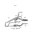
図17は延長管部を床用吸口体部から取り外した状態で、床用吸口体部に設けられた吸口継ぎ手部をほぼ垂直の状態で保持する機構を説明する図である。   FIG. 17 is a view for explaining a mechanism for holding the suction joint provided in the floor suction body portion in a substantially vertical state with the extension pipe portion removed from the floor suction body portion.

吸口継ぎ手部112をほぼ垂直の状態で保持する機構は、図17に示すように、吸口継ぎ手部112を床用吸口体101に前後方向に回動可能に取り付けている回転中心を有する機構の周囲にスプリングバネ805を設け、このスプリングバネ805の一端を床用吸口体101側に固定し、他端を吸口継ぎ手部112側に固定したものである。そして、このスプリングバネ805は、吸口継ぎ手部112を床用吸口体部101の前側に倒すようなバネ力を持ち、吸口継ぎ手部112をほぼ垂直に立てることができるバネ力を有している。また、吸口継ぎ手部112がほぼ垂直な位置からそれ以上前側に倒れないように、別の機械的な機構が設けられている。そして、前述のスプリングバネ805のバネ力は、延長管部114を床用吸口体部101の吸口継ぎ手部112に接続した状態で、延長管部114を手に持って床用吸口体部101と共に持ち上げたとき、床用吸口体部101の重量により自由に動くことが可能な程度に小さなものに設定される。   As shown in FIG. 17, the mechanism for holding the suction joint portion 112 in a substantially vertical state is a mechanism around a mechanism having a rotation center that rotatably attaches the suction joint portion 112 to the floor suction body 101. The spring spring 805 is provided, one end of the spring spring 805 is fixed to the floor suction body 101 side, and the other end is fixed to the suction joint part 112 side. The spring spring 805 has a spring force that tilts the suction joint portion 112 toward the front side of the floor suction body portion 101, and has a spring force that allows the suction joint portion 112 to stand substantially vertically. Further, another mechanical mechanism is provided so that the suction joint portion 112 does not fall further forward from a substantially vertical position. The spring force of the spring spring 805 is the same as that of the floor mouthpiece 101 with the extension pipe 114 held in the hand while the extension pipe 114 is connected to the mouthpiece joint 112 of the floor mouthpiece 101. When lifted, the floor mouthpiece 101 is set to a size small enough to move freely due to the weight of the floor mouthpiece 101.

図18は延長管部を床用吸口体部から取り外した状態で、床用吸口体部に設けられた吸口継ぎ手部をほぼ垂直の状態で保持する他の機構を説明する図、図19は図18におけるロック機構について説明する図である。   FIG. 18 is a diagram for explaining another mechanism for holding the suction joint portion provided in the floor suction body portion in a substantially vertical state with the extension pipe portion removed from the floor suction body portion, and FIG. It is a figure explaining the locking mechanism in 18. FIG.

床用吸口体部101に設けられた吸口継ぎ手部112をほぼ垂直の状態で保持する他のロック機構は、図18に示すように、吸口継ぎ手部112を床用吸口体101に前後方向に回動可能に取り付けている回転中心部に爪部902を有する略円形のクランク901が設けられ、床用吸口体部101側にバネ905により支持されていて爪部903を有するクランクピン904が設けられて構成されている。そして、吸口継ぎ手部112は、図18に示すように、クランク901の爪部902とクランクピン904の爪部903との面が系合することにより、ほぼ垂直な状態を保持することができるようにされている。   As shown in FIG. 18, another locking mechanism for holding the mouthpiece joint portion 112 provided in the floor mouthpiece portion 101 in a substantially vertical state rotates the mouthpiece joint portion 112 to the floor mouthpiece 101 in the front-rear direction. A substantially circular crank 901 having a claw portion 902 is provided at the rotationally attached rotation center portion, and a crank pin 904 having a claw portion 903 supported by a spring 905 is provided on the floor suction body portion 101 side. Configured. Then, as shown in FIG. 18, the suction joint portion 112 can maintain a substantially vertical state by connecting the surfaces of the claw portion 902 of the crank 901 and the claw portion 903 of the crank pin 904. Has been.

図18に示す状態で延長管部114を取り付けて、延長管部114を吸口継ぎ手部112と共に、床用吸口体部101に対して図18の右手側に回動させて、掃除機を使用状態とすると、ロック機構の2つの爪部902と903とが外れて、図19(a)に示すような状態になり、床用吸口体部101は、延長管部114に対して前後方向に自由に回動することができる。図19(b)に示すロック機構の状態は、床用吸口体部101に対して吸口継ぎ手部112をほぼ垂直にして、ロックする寸前の状態を示しており、この図19(b)に示す状態から吸口継ぎ手部112を僅かに図18の左手の方向に回動させれば、図18に示すように、ロック機構の2つの爪部902と903とが系合して、吸口継ぎ手部112をほぼ垂直の状態で保持することになる。   The extension pipe part 114 is attached in the state shown in FIG. 18, and the extension pipe part 114 is rotated together with the suction joint part 112 to the right hand side of FIG. Then, the two claw portions 902 and 903 of the lock mechanism are disengaged, and the state as shown in FIG. 19A is obtained, and the floor mouthpiece portion 101 is free in the front-rear direction with respect to the extension tube portion 114. Can be rotated. The state of the locking mechanism shown in FIG. 19 (b) shows a state just before locking, with the inlet joint portion 112 being substantially perpendicular to the floor inlet body portion 101, as shown in FIG. 19 (b). If the mouthpiece joint 112 is slightly rotated in the direction of the left hand in FIG. 18 from the state, the two claws 902 and 903 of the lock mechanism are combined as shown in FIG. Is held in a substantially vertical state.

図20は延長管部114の先端部にハケブラシ602を取り付けた状態を示す断面図である。   FIG. 20 is a cross-sectional view showing a state where a brush brush 602 is attached to the distal end portion of the extension tube portion 114.

アタッチメントとしてのハケブラシ602を延長管部114の先端部に取り付けることについては、すでに図6により説明したが、図20にはより詳細にその構成を示している。図20から判るように、ハケブラシ602は、延長管部114の先端部に勘合する取り付け管部603の円周に沿って取り付けられており、この取り付け管部603を延長管部114の先端部に取り付ければ、ハケブラシ602を付けたままで、延長管部114を吸口継ぎ手部112に接続することができる。これにより、延長管部114を床用吸口体部101の吸口継ぎ手部112に接続した状態では、ブラシ部が吸口継ぎ手部112の周囲を覆うようになるが、そのまま、床用吸口体部101を使用した掃除を行うことができ、延長管部114を取り外せば直ちに、ハケブラシ602を使用した掃除を行うことができる。   The attachment of the brush 602 as an attachment to the distal end portion of the extension tube portion 114 has already been described with reference to FIG. 6, but FIG. 20 shows the configuration in more detail. As can be seen from FIG. 20, the brush brush 602 is attached along the circumference of the attachment tube portion 603 that fits into the distal end portion of the extension tube portion 114, and this attachment tube portion 603 is attached to the distal end portion of the extension tube portion 114. If attached, the extension pipe part 114 can be connected to the inlet joint part 112 with the brush brush 602 attached. Thus, in a state where the extension pipe portion 114 is connected to the suction joint portion 112 of the floor suction body portion 101, the brush portion covers the periphery of the suction joint portion 112, but the floor suction body portion 101 is not changed as it is. The used cleaning can be performed, and the cleaning using the brush 602 can be performed immediately after the extension pipe portion 114 is removed.

図21は延長管部114を床用吸口体部101の吸口継ぎ手部112に接続する場合のガイド機構について説明する図である。図21において、910は前側ガイド、911は後側ガイドである。   FIG. 21 is a view for explaining a guide mechanism in the case where the extension pipe part 114 is connected to the suction joint part 112 of the floor suction body part 101. In FIG. 21, 910 is a front guide, and 911 is a rear guide.

床用吸口体部101の吸口継ぎ手部112から取り外した延長管部114を再度吸口継ぎ手部112に接続する場合には、単に、吸口継ぎ手部112に延長管部114を差し込めばよいが、その際に、差し込むためのガイド機構があると、より容易に延長管部114を吸口継ぎ手部112に接続することができる。図21(a)に示す前側ガイド910を設けた例は、吸口継ぎ手部112の前側に、半円筒状に形成した透明部材で構成した前側ガイド910を取り付けたものである。また、図21(b)に示す後側ガイド911を設けた例は、吸口継ぎ手部112の後側に、半円筒状に形成した透明部材で構成した後側ガイド911を取り付けたものである。   When connecting the extension pipe part 114 removed from the inlet joint part 112 of the floor inlet body part 101 to the inlet joint part 112 again, the extension pipe part 114 may be simply inserted into the inlet joint part 112. In addition, if there is a guide mechanism for insertion, the extension pipe portion 114 can be more easily connected to the inlet joint portion 112. In the example in which the front guide 910 shown in FIG. 21A is provided, the front guide 910 made of a transparent member formed in a semi-cylindrical shape is attached to the front side of the inlet joint portion 112. Further, in the example in which the rear guide 911 shown in FIG. 21B is provided, the rear guide 911 made of a transparent member formed in a semi-cylindrical shape is attached to the rear side of the suction joint portion 112.

図21(a)、図21(b)に示すガイドは、いずれか一方だけを設ければよいが、両方を設けてもよい。そして、各ガイド910、911を透明部材で構成することにより、吸口継ぎ手部112に延長管部114を差し込む場合に、吸口継ぎ手部112がどのような方向に向いている場合にも、その差し込みの状態を容易に確認することができ、より容易に延長管部114を吸口継ぎ手部112に接続することができる。   Only one of the guides shown in FIGS. 21A and 21B may be provided, but both may be provided. And, by configuring each guide 910, 911 with a transparent member, when the extension pipe part 114 is inserted into the inlet joint part 112, the insertion of the extension joint part 112 is no matter which direction it is oriented. The state can be easily confirmed, and the extension pipe portion 114 can be more easily connected to the inlet joint portion 112.

前述した本発明の実施形態は、吸口継ぎ手部112に接続した延長管部114が床用吸口体部101に対して前後方向に回動ものとして詳細に説明したが、本発明の実施形態は、図2により説明したように、吸口継ぎ手部112がケーシング110に回動可能に接続されて、床用吸口体部101が左右方向に回動することが可能である。そして、吸口継ぎ手部112から延長管部114を取り外した場合に、吸口継ぎ手部112が前後方向の所定の角度位置、前述で説明した例では、ほぼ垂直な角度位置に保持できるだけでなく、左右方向の所定の角度位置に保持されることが望ましい。このような場合の保持機構は、図17〜図19により説明した場合と同様に構成することができる。   In the above-described embodiment of the present invention, the extension pipe portion 114 connected to the suction joint portion 112 has been described in detail as being pivotable in the front-rear direction with respect to the floor suction body portion 101. As described with reference to FIG. 2, the mouthpiece joint 112 is rotatably connected to the casing 110, and the floor mouthpiece 101 can be turned in the left-right direction. When the extension pipe portion 114 is removed from the suction joint portion 112, the suction joint portion 112 can be held at a predetermined angular position in the front-rear direction, in the above-described example, at a substantially vertical angular position, It is desirable to be held at a predetermined angular position. The holding mechanism in such a case can be configured similarly to the case described with reference to FIGS.

また、本発明の実施形態は、前述した説明からも明らかなように、吸口継ぎ手部112に接続した延長管部114の床用吸口体部101に対する前後方向に回動位置が床用吸口体部101の側に、左右方向の回動位置が吸口継ぎ手部112の側にあることになる。本発明は、吸口継ぎ手部112に接続した延長管部114の床用吸口体部101に対する前後方向に回動位置が吸口継ぎ手部112の側に、左右方向の回動位置が床用吸口体部101の側にあるような場合にも適用することができる。   Further, as is apparent from the above description, the embodiment of the present invention is such that the rotational position of the extension pipe portion 114 connected to the suction joint portion 112 in the front-rear direction with respect to the floor suction body portion 101 is the floor suction body portion. On the 101 side, the rotational position in the left-right direction is on the inlet joint portion 112 side. In the present invention, the extension position of the extension pipe part 114 connected to the suction joint part 112 in the front-rear direction with respect to the floor suction body part 101 is on the side of the suction joint part 112, and the rotational position in the left-right direction is the floor suction body part. The present invention can also be applied to the case of being on the 101 side.

図22は左右方向の回動位置が床用吸口体部101の側にある場合の床用吸口体部と吸口継ぎ手部との部位の構成を説明する外観図、図23は図22における床用吸口体部から延長管部軸線方向の断面図である。   FIG. 22 is an external view for explaining the configuration of the parts of the floor suction body portion and the suction joint portion when the horizontal rotation position is on the floor suction body portion 101 side, and FIG. 23 is for the floor in FIG. It is sectional drawing of an extension pipe part axial direction from a suction body part.

図22に示す例は、下ケース102と上ケース103とを有する床用吸口体部101の後部に、回動Aとして示すように、床用吸口体部101が左右方向に回動可能に吸口継ぎ手部112のケーシング110に取り付けられて構成され、また、ケーシング110に吸口継ぎ手部112が前後方向に回転軸を中心に回動可能に取り付けられて構成されている。吸口継ぎ手部112の端部には、弾性体により構成されたピンF208の端部が露出している。吸口継ぎ手部112の構成と、これに接続される延長管部114の構成は、前述までに説明したものと同一である。なお、床用吸口体部101が左右方向に回動可能に吸口継ぎ手部112のケーシング110に取り付けられる機構については、よく知られているものであるため、ここでの説明は省略する。   In the example shown in FIG. 22, the floor mouthpiece body portion 101 having the lower case 102 and the upper case 103 has a mouthpiece so that the floor mouthpiece portion 101 can turn in the left-right direction, as shown as rotation A. The joint portion 112 is configured to be attached to the casing 110, and the inlet joint portion 112 is configured to be attached to the casing 110 so as to be rotatable about the rotation axis in the front-rear direction. At the end portion of the mouthpiece joint portion 112, the end portion of the pin F208 made of an elastic body is exposed. The configuration of the suction joint portion 112 and the configuration of the extension pipe portion 114 connected thereto are the same as those described above. Since the mechanism for attaching the floor suction body portion 101 to the casing 110 of the suction joint portion 112 so as to be rotatable in the left-right direction is well known, description thereof is omitted here.

前述したように構成される例において、図23に示すように、床用吸口体部101の上ケース103のケーシング110の側には、上ケース凸部920が設けられており、吸口継ぎ手部110は、回転軸Bを中心として前後方向に回動可能である。また、床用吸口体部101を回転中心軸Aを中心に左右方向に回動可能とする機構の一部を持つ下ケース102には、ピンCバネ921とピンC922とが設けられており、床用吸口体部101が回転していない状態で、ケーシング110に設けた凹部にピンCが系合して、回動動作に対する抑止を行う。   In the example configured as described above, as shown in FIG. 23, an upper case convex portion 920 is provided on the casing 110 side of the upper case 103 of the floor mouthpiece portion 101, and the mouthpiece joint portion 110 is provided. Is rotatable in the front-rear direction around the rotation axis B. In addition, a pin C spring 921 and a pin C922 are provided in the lower case 102 having a part of a mechanism that allows the floor mouthpiece 101 to be rotated in the left-right direction about the rotation center axis A. In a state in which the floor mouthpiece 101 is not rotating, the pin C is engaged with the recess provided in the casing 110 to suppress the rotation operation.

前述したような状態から、図示しない延長管部114が接続された吸口継ぎ手部112が略垂直な状態に回動させられると、前述した床用吸口体部101の上ケース103のケーシング110に設けられた上ケース凸部920が、吸口継ぎ手部112の端部に設けられたピンF208の先端を押すことになる。この結果、前述ですでに接続したと同様に、ピンF208の作用により、吸口継ぎ手部112と延長管部114とを接続していたロックが外れて、延長管部114を吸口継ぎ手部112から取り外すことが可能となる。なお、吸口継ぎ手部112から延長管部114を取り外した後の吸口継ぎ手部112の所定の角度位置での保持については、図17、図18により接続した場合と同様な構成で行うことができる。   From the state as described above, when the inlet joint portion 112 to which the extension pipe portion 114 (not shown) is connected is turned to a substantially vertical state, the casing 110 of the upper case 103 of the floor inlet body portion 101 described above is provided. The formed upper case convex portion 920 pushes the tip of the pin F208 provided at the end of the suction joint portion 112. As a result, as already described above, the lock connecting the suction joint portion 112 and the extension pipe portion 114 is released by the action of the pin F208, and the extension pipe portion 114 is removed from the suction joint portion 112. It becomes possible. In addition, about the holding | maintenance in the predetermined | prescribed angular position of the suction joint part 112 after removing the extension pipe part 114 from the suction joint part 112, it can carry out with the structure similar to the case where it connects by FIG. 17, FIG.

本発明の一実施形態による電気掃除機の床用吸口体部、床用吸口体部に設けられた吸口継ぎ手部に接続された延長管部の部位の構成を説明する外観図である。It is an external view explaining the structure of the site | part of the extension pipe part connected to the suction mouth part provided in the floor suction body part of the vacuum cleaner by one Embodiment of this invention, and the floor suction body part. 図1により説明した床用吸口体部、床用吸口体部に設けられた吸口継ぎ手部に接続された延長管部の部位の内部構成を説明する分解斜視図である。It is a disassembled perspective view explaining the internal structure of the site | part of the extension pipe part connected to the suction port part provided in the floor suction body part demonstrated in FIG. 1, and the floor suction body part. 本発明の一実施形態による電気掃除機の通常の使用状態の外観を示す図である。It is a figure which shows the external appearance of the normal use condition of the vacuum cleaner by one Embodiment of this invention. 本発明の一実施形態による電気掃除機の延長管部を取り外すために、延長管部をほぼ垂直に立てた状態を示す図である。It is a figure which shows the state which stood the extension pipe part upright substantially, in order to remove the extension pipe part of the vacuum cleaner by one Embodiment of this invention. 図4に示す状態から延長管部を取り外した状態を示す図である。It is a figure which shows the state which removed the extension pipe part from the state shown in FIG. 延長管部を取り外して他のアタッチメントを延長管部に取り付けた状態を示す図である。It is a figure which shows the state which removed the extension pipe part and attached the other attachment to the extension pipe part. 足踏みペダルを用いて延長管部を床用吸口体部101から取り外す機構を説明するための延長管部を略水平状態とした場合を示す断面図である。It is sectional drawing which shows the case where the extension pipe part for demonstrating the mechanism which removes an extension pipe part from the floor mouthpiece part 101 using a foot pedal is made into a substantially horizontal state. 足踏みペダルを用いて延長管部を床用吸口体部から取り外す機構を説明するための延長管部をほぼ垂直状態とした場合を示す断面図である。It is sectional drawing which shows the case where the extension pipe part for demonstrating the mechanism which removes an extension pipe part from a floor mouthpiece part using a foot pedal is made into a substantially perpendicular state. 図8に示す状態で足踏みペダルを押し下げた場合を示す断面図である。It is sectional drawing which shows the case where a foot pedal is pushed down in the state shown in FIG. 図9に示す状態から延長管部を引き抜いて取り外した状態を示す断面図である。FIG. 10 is a cross-sectional view illustrating a state in which the extension pipe portion is pulled out and removed from the state illustrated in FIG. 9. 延長管部が傾斜している状態を示す概略断面図である。It is a schematic sectional drawing which shows the state in which the extension pipe part inclines. 図11に示す状態で足踏みペダルを押し下げた状態を示す図である。It is a figure which shows the state which pushed down the foot pedal in the state shown in FIG. 延長管部をほぼ垂直に立てるだけで延長管部を吸口継ぎ手部から取り外すことを可能とした例での延長管部が略水平にされた状態を示す概略断面図である。FIG. 5 is a schematic cross-sectional view showing a state in which the extension pipe part is made substantially horizontal in an example in which the extension pipe part can be removed from the suction joint part only by standing the extension pipe part almost vertically. 図13に示す状態から延長管部を立てた状態を示す図である。It is a figure which shows the state which stood the extension pipe part from the state shown in FIG. 延長管部をほぼ垂直に立てるだけで延長管部を吸口継ぎ手部から取り外すことを可能とした他の例での延長管部が略水平にされた状態を示す概略断面図である。It is a schematic sectional drawing which shows the state by which the extension pipe part in the other example which made it possible to remove an extension pipe part from a suction joint part only by standing up an extension pipe part substantially vertically was made substantially horizontal. 図15に示す状態から延長管部を立てた状態を示す図である。It is a figure which shows the state which stood the extension pipe part from the state shown in FIG. 延長管部を床用吸口体部から取り外した状態で、床用吸口体部に設けられた吸口継ぎ手部をほぼ垂直の状態で保持する機構を説明する図である。It is a figure explaining the mechanism which hold | maintains the suction-joint part provided in the floor suction body part in the substantially vertical state in the state which removed the extension pipe part from the floor suction body part. 延長管部を床用吸口体部から取り外した状態で、床用吸口体部に設けられた吸口継ぎ手部をほぼ垂直の状態で保持する他の機構を説明する図である。It is a figure explaining the other mechanism which hold | maintains the suction-joint part provided in the floor suction body part in a substantially perpendicular state in the state which removed the extension pipe part from the floor suction body part. 図18におけるロック機構について説明する図である。It is a figure explaining the locking mechanism in FIG. 延長管部の先端部にハケブラシを取り付けた状態を示す断面図である。It is sectional drawing which shows the state which attached the brush to the front-end | tip part of an extension pipe part. 延長管部を床用吸口体部の吸口継ぎ手部に接続する場合のガイド機構について説明する図である。It is a figure explaining a guide mechanism in the case of connecting an extension pipe part to a mouthpiece joint part of a mouthpiece body part for floors. 左右方向の回動位置が床用吸口体部の側にある場合の床用吸口体部と吸口継ぎ手部との部位の構成を説明する外観図である。It is an external view explaining the structure of the site | part of the floor suction body part and suction mouth joint part in case the rotation position of the left-right direction exists in the floor suction body part side. 図22における床用吸口体部から延長管部軸線方向の断面図である。It is sectional drawing of the extension pipe part axial direction from the floor suction body part in FIG.

符号の説明Explanation of symbols

101 床用吸口体部
102 下ケース
103 上ケース
104 バンパー
105 タイヤ
106 リンク
107 ピンD
108 ケーシングカバー
109 ローラ
110 ケーシング
111 足踏みペダル
112 吸口継ぎ手部
113 継ぎ手カバー
114 延長管部
115 延長管カバー
116 クランプ
117 クランプの突起部
201 タイヤシャフト
202 リンクシャフト
203 足踏みペダルシャフト
204 足踏みペダルバネ
205 流路カバー
206 回動カバー
207 ピンDシャフト
208 ピンF
209 ピンFバネ
210 クランプバネ
301 掃除機本体
302 ホース部
303 グリップ部
304 手元スイッチ
601 隙間用吸口
602 ハケブラシ
910 後側ガイド
911 前側ガイド
101 Suction body for floor 102 Lower case 103 Upper case 104 Bumper 105 Tire 106 Link 107 Pin D
108 Casing cover 109 Roller 110 Casing 111 Foot pedal 112 Suction joint 113 Joint cover 114 Extension pipe part 115 Extension pipe cover 116 Clamp 117 Clamp projection 201 Tire shaft 202 Link shaft 203 Foot pedal shaft 204 Foot pedal spring 205 Flow path cover 206 Rotating cover 207 pin D shaft 208 pin F
209 Pin F spring 210 Clamp spring 301 Vacuum cleaner body 302 Hose part 303 Grip part 304 Hand switch 601 Clearance inlet 602 Brush brush 910 Rear guide 911 Front guide

Claims (3)

吸口体部と延長管部とを備えた電気掃除機において、
前記延長管部を前記吸口体部に装着したときに両者をロックさせ、前記吸口体部の被清掃面に対向する底面と前記延長管部とのなす角度が所定角度開いたときに、前記延長管部と前記吸口体部とを分離可能とするロック機構が、前記吸口体部と前記延長管部とにわたって設けられていることを特徴とする電気掃除機。
In a vacuum cleaner comprising a mouthpiece and an extension tube,
When the extension pipe part is attached to the mouthpiece body part, both are locked, and when the angle formed between the bottom face of the mouthpiece body part facing the surface to be cleaned and the extension pipe part is opened by a predetermined angle, the extension is performed. The vacuum cleaner characterized by the fact that the lock mechanism which can isolate | separate a pipe part and the said suction body part is provided over the said suction body part and the said extension pipe part.
請求項1記載の電気掃除機において、
前記吸口体部は、吸口体と、前記吸口体と前記延長管部との間に設けられて両者を連通可能とすると共に前記吸口体の進退方向に傾動する継ぎ手部とを有し、
前記ロック機構は、前記継ぎ手部に設けられると共に一方に係合部を有し他方に被押圧部を有した手段と、前記延長管部に設けられると共に前記係合部に係合される被係合部と、前記被押圧部に当接して前記係合部を前記被係合部に係合する方向に付勢する弾性部材と、前記吸口体部に設けられると共に前記底面と前記延長管部とのなす角度が前記所定角度開いたときに前記被押圧部を前記弾性部材に抗して押圧して前記係合部と前記被係合部との係合を外すことによりロックを解除する押圧部とを備えたことを特徴とする電気掃除機。
The vacuum cleaner according to claim 1,
The mouthpiece portion includes a mouthpiece, and a joint portion that is provided between the mouthpiece and the extension pipe portion so as to allow both to communicate and tilts in the advancing and retreating direction of the mouthpiece.
The locking mechanism includes means having a pressed portion on the other has an engaging portion on one with is provided in the joint portion, the engageable to be engaged with the engaging portion together with the provided in the extension pipe unit A mating portion; an elastic member that abuts against the pressed portion and urges the engaging portion in a direction to engage the engaged portion; and the bottom surface and the extension pipe portion provided on the suction body portion pressing to unlock by removing the engagement between the engaged portion and the engagement portion angle presses against the pressed portion on the elastic member when opened wherein the predetermined angle with And a vacuum cleaner characterized by comprising a part.
請求項1または2記載の電気掃除機において、
前記延長管部の前記吸口体部との接続部位に掃除用の他のアタッチメントを設けたことを特徴とする電気掃除機。
The vacuum cleaner according to claim 1 or 2,
A vacuum cleaner characterized in that another attachment for cleaning is provided at a site where the extension pipe part is connected to the mouthpiece part.
JP2004104803A 2004-03-31 2004-03-31 Vacuum cleaner Expired - Lifetime JP4417758B2 (en)

Priority Applications (1)

Application Number Priority Date Filing Date Title
JP2004104803A JP4417758B2 (en) 2004-03-31 2004-03-31 Vacuum cleaner

Applications Claiming Priority (1)

Application Number Priority Date Filing Date Title
JP2004104803A JP4417758B2 (en) 2004-03-31 2004-03-31 Vacuum cleaner

Related Child Applications (2)

Application Number Title Priority Date Filing Date
JP2009063299A Division JP4713650B2 (en) 2009-03-16 2009-03-16 Electric vacuum cleaner
JP2009063291A Division JP4734434B2 (en) 2009-03-16 2009-03-16 Vacuum cleaner

Publications (3)

Publication Number Publication Date
JP2005287659A JP2005287659A (en) 2005-10-20
JP2005287659A5 JP2005287659A5 (en) 2009-03-12
JP4417758B2 true JP4417758B2 (en) 2010-02-17

Family

ID=35321275

Family Applications (1)

Application Number Title Priority Date Filing Date
JP2004104803A Expired - Lifetime JP4417758B2 (en) 2004-03-31 2004-03-31 Vacuum cleaner

Country Status (1)

Country Link
JP (1) JP4417758B2 (en)

Families Citing this family (4)

* Cited by examiner, † Cited by third party
Publication number Priority date Publication date Assignee Title
CN101108102B (en) * 2006-07-19 2011-09-07 乐金电子(天津)电器有限公司 Suction tube structure of vacuum cleaner suction head
CN101862160B (en) * 2009-04-20 2013-08-28 日立空调·家用电器株式会社 Electric dust collector
JP5386260B2 (en) * 2009-07-28 2014-01-15 日立アプライアンス株式会社 Vacuum cleaner mouthpiece and electric vacuum cleaner using the same
US11723499B2 (en) 2019-06-11 2023-08-15 Aktiebolaget Electrolux Vacuum cleaner nozzle

Also Published As

Publication number Publication date
JP2005287659A (en) 2005-10-20

Similar Documents

Publication Publication Date Title
JP4825885B2 (en) Vacuum cleaner
CA2647366A1 (en) Electric vacuum cleaner, and vacuum cleaner hose
JP4417758B2 (en) Vacuum cleaner
JP4678682B2 (en) Suction port
JP4713958B2 (en) Electric vacuum cleaner
AU2008203381B2 (en) Cord-reel apparatus and vacuum cleaner having the same
JP4734434B2 (en) Vacuum cleaner
JP4258730B2 (en) Electric vacuum cleaner
JP4480595B2 (en) Upright type vacuum cleaner
JP4713650B2 (en) Electric vacuum cleaner
JP2007190190A (en) Vacuum cleaner
JP4559920B2 (en) Vacuum cleaner
JP5100444B2 (en) Vacuum cleaner and suction port
JP2009061209A (en) Suction tool and vacuum cleaner
JP5386260B2 (en) Vacuum cleaner mouthpiece and electric vacuum cleaner using the same
JP2006034593A (en) Vacuum cleaner
JP4047262B2 (en) Upright type vacuum cleaner
JP3400948B2 (en) Electric vacuum cleaner
JP2005312788A (en) Vacuum cleaner
JP2018011676A (en) Vacuum cleaner
JP4309315B2 (en) Electric vacuum cleaner
JP4241595B2 (en) Electric vacuum cleaner
JP2005287659A5 (en)
JP5117965B2 (en) Electric vacuum cleaner
JP2021194195A (en) Vacuum cleaner

Legal Events

Date Code Title Description
A711 Notification of change in applicant

Free format text: JAPANESE INTERMEDIATE CODE: A712

Effective date: 20060911

RD02 Notification of acceptance of power of attorney

Free format text: JAPANESE INTERMEDIATE CODE: A7422

Effective date: 20060921

A621 Written request for application examination

Free format text: JAPANESE INTERMEDIATE CODE: A621

Effective date: 20070309

A521 Written amendment

Free format text: JAPANESE INTERMEDIATE CODE: A523

Effective date: 20090123

A977 Report on retrieval

Free format text: JAPANESE INTERMEDIATE CODE: A971007

Effective date: 20090814

A131 Notification of reasons for refusal

Free format text: JAPANESE INTERMEDIATE CODE: A131

Effective date: 20090901

A521 Written amendment

Free format text: JAPANESE INTERMEDIATE CODE: A523

Effective date: 20091026

TRDD Decision of grant or rejection written
A01 Written decision to grant a patent or to grant a registration (utility model)

Free format text: JAPANESE INTERMEDIATE CODE: A01

Effective date: 20091117

A01 Written decision to grant a patent or to grant a registration (utility model)

Free format text: JAPANESE INTERMEDIATE CODE: A01

A61 First payment of annual fees (during grant procedure)

Free format text: JAPANESE INTERMEDIATE CODE: A61

Effective date: 20091126

R150 Certificate of patent or registration of utility model

Ref document number: 4417758

Country of ref document: JP

Free format text: JAPANESE INTERMEDIATE CODE: R150

Free format text: JAPANESE INTERMEDIATE CODE: R150

FPAY Renewal fee payment (event date is renewal date of database)

Free format text: PAYMENT UNTIL: 20121204

Year of fee payment: 3

FPAY Renewal fee payment (event date is renewal date of database)

Free format text: PAYMENT UNTIL: 20131204

Year of fee payment: 4

S531 Written request for registration of change of domicile

Free format text: JAPANESE INTERMEDIATE CODE: R313531

S533 Written request for registration of change of name

Free format text: JAPANESE INTERMEDIATE CODE: R313533

R350 Written notification of registration of transfer

Free format text: JAPANESE INTERMEDIATE CODE: R350