JP4414835B2 - Clutch cover assembly - Google Patents

Clutch cover assembly Download PDF

Info

Publication number
JP4414835B2
JP4414835B2 JP2004224343A JP2004224343A JP4414835B2 JP 4414835 B2 JP4414835 B2 JP 4414835B2 JP 2004224343 A JP2004224343 A JP 2004224343A JP 2004224343 A JP2004224343 A JP 2004224343A JP 4414835 B2 JP4414835 B2 JP 4414835B2
Authority
JP
Japan
Prior art keywords
clutch cover
load
cover assembly
elastic member
clutch
Prior art date
Legal status (The legal status is an assumption and is not a legal conclusion. Google has not performed a legal analysis and makes no representation as to the accuracy of the status listed.)
Expired - Fee Related
Application number
JP2004224343A
Other languages
Japanese (ja)
Other versions
JP2006046368A (en
JP2006046368A5 (en
Inventor
範久 植之原
Current Assignee (The listed assignees may be inaccurate. Google has not performed a legal analysis and makes no representation or warranty as to the accuracy of the list.)
Exedy Corp
Original Assignee
Exedy Corp
Priority date (The priority date is an assumption and is not a legal conclusion. Google has not performed a legal analysis and makes no representation as to the accuracy of the date listed.)
Filing date
Publication date
Application filed by Exedy Corp filed Critical Exedy Corp
Priority to JP2004224343A priority Critical patent/JP4414835B2/en
Publication of JP2006046368A publication Critical patent/JP2006046368A/en
Publication of JP2006046368A5 publication Critical patent/JP2006046368A5/ja
Application granted granted Critical
Publication of JP4414835B2 publication Critical patent/JP4414835B2/en
Expired - Fee Related legal-status Critical Current
Anticipated expiration legal-status Critical

Links

Images

Description

本発明は、クラッチカバー組立体、特に、エンジンのフライホイールにクラッチディス組立体の摩擦部材を押し付け及び押し付け解除するためものに関する。   The present invention relates to a clutch cover assembly, and more particularly to pressing and releasing a friction member of a clutch disassembly against a flywheel of an engine.

クラッチカバー組立体は、一般に、エンジンのフライホイールに装着され、エンジンの駆動力をトランスミッション側に伝達するために用いられている。このようなクラッチカバー組立体は、主に、フライホイールに固定されるクラッチカバーと、フライホイールとの間でクラッチディスク組立体の摩擦部材を挟持するためのプレッシャープレートと、プレッシャープレートをフライホイール側に押圧するためのダイヤフラムスプリングとから構成されている。ダイヤフラムスプリングは、環状弾性部と、環状弾性部の内周縁から径方向内側に延びる複数のレバー部とからなる。ダイヤフラムスプリングは、プレッシャープレートを押圧する機能とともに、プレッシャープレートへの押圧を解除するためのレバー機能も有している。   The clutch cover assembly is generally mounted on an engine flywheel and used to transmit the driving force of the engine to the transmission side. Such a clutch cover assembly mainly includes a clutch cover fixed to the flywheel, a pressure plate for sandwiching the friction member of the clutch disk assembly between the flywheel, and the pressure plate on the flywheel side. It is comprised from the diaphragm spring for pressing. The diaphragm spring includes an annular elastic portion and a plurality of lever portions extending radially inward from the inner peripheral edge of the annular elastic portion. The diaphragm spring has a function of pressing the pressure plate and a lever function for releasing the pressure on the pressure plate.

クラッチカバー組立体の押付荷重特性を説明する。押付荷重特性とは、ダイヤフラムスプリングの荷重特性において押付荷重としての使用領域を表すものである。例えば図6に示すように、押付荷重特性20において、クラッチカバー組立体の有効使用領域(摩耗代)は、一定の押付荷重が得られる領域(新品のセットライン25から、摩擦部材が摩耗限界まで達したウェアーライン26まで)である。   The pressing load characteristic of the clutch cover assembly will be described. The pressing load characteristic represents a use area as a pressing load in the load characteristic of the diaphragm spring. For example, as shown in FIG. 6, in the pressing load characteristic 20, the effective use area (wear allowance) of the clutch cover assembly is an area where a constant pressing load can be obtained (from the new set line 25 to the wear limit of the friction member). To the wear line 26).

次に、クラッチカバー組立体のレリーズ荷重特性について説明する。レリーズ荷重特性とは、レリーズレバーの作動量(レバーストローク量)と、レリーズレバー先端に作用する荷重(レリーズ荷重)の関係を表すものである。例えば、図9に示すように、レリーズ荷重特性60は、レバー作動量ゼロから直線的に増大していく第1部分61と、なだらかに小さくなっていく第2部分62とを有しており、両者の接点がピーク63となっている。第1部分61はダイヤフラムスプリングのレバー剛性を表しており、第2部分62は押付荷重特性におけるセットラインから図右側への変化に対応している。   Next, the release load characteristics of the clutch cover assembly will be described. The release load characteristic represents the relationship between the operation amount (lever stroke amount) of the release lever and the load (release load) acting on the tip of the release lever. For example, as shown in FIG. 9, the release load characteristic 60 has a first portion 61 that increases linearly from zero lever operation amount, and a second portion 62 that gradually decreases. The point of contact between them is a peak 63. The first portion 61 represents the lever rigidity of the diaphragm spring, and the second portion 62 corresponds to a change in the pressing load characteristic from the set line to the right side in the figure.

押付荷重特性20は、図6に示すように、ダイヤフラムスプリングの変位量がゼロから大きくなるにつれて、一定の割合で増大していくが、たわみ量がある点(ピーク点)を越えると以後はなだらかに減少していき、さらにあるたわみ量を超えるとなだらかに増大していく。このため、有効使用領域内では、山部分21(上側に凸となる部分)となっており、摩擦部材の摩耗が大きくなるにつれて(セットラインが図の左側に移動するにつれて)押付荷重が大きくなる。すなわち、摩擦部材が摩耗すると、レリーズ荷重が大きくなり、さらにはクラッチペダル踏力が大きくなってしまう。   As shown in FIG. 6, the pressing load characteristic 20 increases at a constant rate as the displacement amount of the diaphragm spring increases from zero. However, when the deflection amount exceeds a certain point (peak point), the pressing load characteristic 20 gradually increases. It decreases gradually, and when it exceeds a certain amount of deflection, it gradually increases. For this reason, in the effective use area | region, it is the peak part 21 (part which becomes convex upward), and the pressing load becomes large as wear of a friction member becomes large (as a set line moves to the left side of a figure). . That is, when the friction member wears, the release load increases and the clutch pedal depression force also increases.

そこで従来より、押付荷重特性におけるピークをカットするための構造として、摩擦部材が摩耗するとダイヤフラムスプリングの荷重に対して対抗するように作用する荷重を発生させる弾性部材を用いるピークカットクラッチが知られている。ピークカットクラッチでは、ダイヤフラムスプリングの特性の山部分に弾性部材の特性の反対向きの山部分の特性が重ね合わせられ、その結果、合成荷重において平坦部分が得られる(例えば、特許文献1を参照。)。
実開平3−22131号
Therefore, conventionally, as a structure for cutting the peak in the pressing load characteristic, a peak cut clutch using an elastic member that generates a load that acts to counteract the load of the diaphragm spring when the friction member is worn is known. Yes. In the peak cut clutch, the peak portion of the diaphragm spring is overlapped with the peak portion characteristic opposite to that of the elastic member, and as a result, a flat portion is obtained in the combined load (see, for example, Patent Document 1). ).
ACT 3-22131

摩擦部材におけるクッショニング機能による低レリーズ荷重化を説明する。クッショニング機能がない場合は、図9のレリーズ荷重特性において、レリーズ荷重特性60は、荷重バランス点63までは線形に変化し、そこからなだらかに小さくなっていき、またなだらかに大きくなっていく。また、荷重バランス点63まではプレッシャープレートの切れ量はゼロである。摩擦部材がクッション機能を有している場合は、クッションの反発力によりレリーズ開始と同時にプレッシャープレートの移動が始まり荷重バランス点63においてある程度移動している。このことは荷重バランス点での押付荷重が図6の右方向にシフトしていることを意味している。その結果、図9において荷重バランス点63におけるレリーズ荷重は、クッショニング機能がない場合に比べ大幅に小さくなる。以上の結果が得られるのは、図6の押付荷重特性において、プレッシャープレートがレリーズ動作中に負勾配部分を移動するからである。したがって、摩擦部材の摩耗によってセットラインの位置が変われば平坦部分や正勾配部分を移動することも考えられる。その場合は、摩擦部材におけるクッショニング機能による低レリーズ荷重化は得られない。   The reduction of the release load by the cushioning function in the friction member will be described. When there is no cushioning function, in the release load characteristic of FIG. 9, the release load characteristic 60 linearly changes up to the load balance point 63, and gradually decreases and increases gradually. Further, the pressure plate has a zero cut amount up to the load balance point 63. When the friction member has a cushion function, the pressure plate starts moving at the same time as the release starts due to the repulsive force of the cushion, and moves to some extent at the load balance point 63. This means that the pressing load at the load balance point is shifted to the right in FIG. As a result, the release load at the load balance point 63 in FIG. 9 is significantly smaller than when there is no cushioning function. The above result is obtained because the pressure plate moves in the negative gradient portion during the release operation in the pressing load characteristic of FIG. Therefore, if the position of the set line changes due to wear of the friction member, it may be possible to move the flat portion or the positive gradient portion. In that case, a low release load due to the cushioning function in the friction member cannot be obtained.

本発明の課題は、摩擦部材が摩耗した状態でも摩擦部材におけるクッショニング機能による低レリーズ荷重化を実現することにある。   An object of the present invention is to realize a low release load by a cushioning function in a friction member even when the friction member is worn.

請求項1に記載のクラッチカバー組立体は、エンジンのフライホイールにクラッチディス組立体のクッショニング機能付き摩擦部材を押し付け及び押し付け解除するためのものであって、クラッチカバーと、プレッシャープレートと、ダイヤフラムスプリングと、第1弾性部材と、第2弾性部材とを備えている。クラッチカバーは、フライホイールに固定されている。プレッシャープレートは、クラッチカバーに対して相対回転不能に連結され、フライホイールとの間で摩擦部材を挟むための部材である。ダイヤフラムスプリングは、クラッチカバーに支持され、プレッシャープレートをフライホイール側に付勢する。第1弾性部材は、クラッチカバーに支持され、ダイヤフラムスプリングの付勢力に対抗する荷重を発生することで、ダイヤフラムスプリングの変位量に対するプレッシャープレートへの押付荷重の変化を平坦化するための部材である。第2弾性部材は、クラッチカバーに支持され、レリーズ動作中にダイヤフラムスプリングの付勢力に対抗する荷重を発生することで、摩擦部材のクッショニング機能によってダイヤフラムスプリングの変位量が増大する過程において、プレッシャープレートへの押付荷重を減らしていくための部材である。   A clutch cover assembly according to claim 1 is for pressing and releasing a friction member with a cushioning function of a clutch disassembly against an engine flywheel, the clutch cover, a pressure plate, and a diaphragm spring. And a first elastic member and a second elastic member. The clutch cover is fixed to the flywheel. The pressure plate is connected to the clutch cover so as not to rotate relative to the clutch cover, and is a member for sandwiching the friction member with the flywheel. The diaphragm spring is supported by the clutch cover and biases the pressure plate toward the flywheel. The first elastic member is a member that is supported by the clutch cover and generates a load that opposes the urging force of the diaphragm spring, thereby flattening a change in the pressing load on the pressure plate with respect to the displacement amount of the diaphragm spring. . The second elastic member is supported by the clutch cover, and generates a load that opposes the urging force of the diaphragm spring during the release operation. In this process, the displacement amount of the diaphragm spring increases due to the cushioning function of the friction member. It is a member for reducing the pressing load to the.

このクラッチカバー組立体では、第1弾性部材によって、ダイヤフラムスプリングの変位量に対するプレッシャープレートへの押付荷重の変化が平坦化させられる。次に、第2弾性部材によって、摩擦部材におけるクッショニング機能による低レリーズ荷重化を摩擦部材が摩耗した状態でも実現することができる。第2弾性部材が、レリーズ動作中にダイヤフラムスプリングの付勢力に対抗する荷重を発生することで、摩擦部材のクッショニング機能によってダイヤフラムスプリングの変位量が増大する過程において、プレッシャープレートへの押付荷重を減らしていくからである。   In this clutch cover assembly, the change of the pressing load on the pressure plate with respect to the displacement amount of the diaphragm spring is flattened by the first elastic member. Next, with the second elastic member, the release load can be reduced by the cushioning function of the friction member even when the friction member is worn. The second elastic member generates a load that opposes the urging force of the diaphragm spring during the release operation, thereby reducing the pressing load on the pressure plate in the process of increasing the displacement amount of the diaphragm spring by the cushioning function of the friction member. Because it goes.

請求項2に記載のクラッチカバー組立体では、請求項1において、第2弾性部材は、クラッチ連結状態からレリーズ動作が進むにつれて荷重を大きくしていく。   In a clutch cover assembly according to a second aspect, in the first aspect, the second elastic member increases the load as the release operation proceeds from the clutch connected state.

請求項3に記載のクラッチカバー組立体では、請求項1又は2において、第2弾性部材は複数の弾性部材を組み合わせて構成されている。   According to a third aspect of the present invention, in the clutch cover assembly according to the first or second aspect, the second elastic member is configured by combining a plurality of elastic members.

このクラッチカバー組立体では、複数の弾性部材によって好ましい特性を実現できる。   In this clutch cover assembly, preferable characteristics can be realized by a plurality of elastic members.

請求項4に記載のクラッチカバー組立体では、請求項1〜3のいずれかにおいて、第2弾性部材はクラッチカバーの摩擦部材側と軸方向反対側に配置されている。   In a clutch cover assembly according to a fourth aspect, in any one of the first to third aspects, the second elastic member is disposed on the side opposite to the friction member side of the clutch cover in the axial direction.

このクラッチカバー組立体では、第2弾性部材の組み付けや取り外しが容易である。   In this clutch cover assembly, the second elastic member can be easily assembled and removed.

請求項5に記載のクラッチカバー組立体は、請求項において、プレッシャープレートからクラッチカバー側に延びる支持部材をさらに備えている。第2弾性部材は、支持部材に対して摩擦部材側と軸方向反対側に荷重を付与する。 According to a fifth aspect of the present invention, the clutch cover assembly according to the fourth aspect further includes a support member extending from the pressure plate to the clutch cover side. The second elastic member applies a load to the support member on the friction member side and the axially opposite side.

請求項6に記載のクラッチカバー組立体では、請求項1〜5のいずれかにおいて、第2弾性部材はコーンスプリングである。   According to a sixth aspect of the present invention, in the clutch cover assembly according to the first aspect, the second elastic member is a cone spring.

請求項7に記載のクラッチカバー組立体では、請求項1において、摩擦部材の摩耗に対して第2弾性部材の姿勢を維持するための摩耗補償機構をさらに備えている。   According to a seventh aspect of the present invention, the clutch cover assembly according to the first aspect further includes a wear compensation mechanism for maintaining the posture of the second elastic member against the wear of the friction member.

このクラッチカバー組立体では、摩耗補償機構によって、第2弾性部材の姿勢は摩擦部材が摩耗しても維持される。   In this clutch cover assembly, the posture of the second elastic member is maintained by the wear compensation mechanism even when the friction member is worn.

請求項8に記載のクラッチカバー組立体では、請求項7において、摩耗補償機構は、摩擦部材が摩耗したときに第2弾性部材を摩耗前の姿勢に復帰させるための復帰機構を有している。   The clutch cover assembly according to claim 8, wherein the wear compensation mechanism has a return mechanism for returning the second elastic member to a pre-wear position when the friction member is worn. .

このクラッチカバー組立体では、第2弾性部材は復帰機構によって元の姿勢に復帰させられる。   In this clutch cover assembly, the second elastic member is returned to the original posture by the return mechanism.

請求項9に記載のクラッチカバー組立体では、請求項8において、復帰機構は、プレッシャープレートからクラッチカバー側に延びる支持部材と、支持部材に対してねじで係合して第2弾性部材から摩擦部材側と軸方向反対側に荷重を受ける支持係合部材と、支持係合部材が摩擦部材側と軸方向反対側に移動する方向に回転するよう支持係合部材に常時トルクを付与する第3弾性部材とを有する。 According to a ninth aspect of the present invention, in the clutch cover assembly according to the eighth aspect, the return mechanism includes a support member that extends from the pressure plate toward the clutch cover side, and a screw that engages the support member with a screw and friction from the second elastic member. and support and engagement member for receiving a load to member side axially opposite the third the support and engagement member imparts always torque to the support engaging member to rotate in a direction to move the friction member side axially opposite And an elastic member.

このクラッチカバー組立体では、支持係合部材は第2弾性部材と第3弾性部材の荷重バランスによって支持部材に対して軸方向に位置決めされている。この状態で摩擦部材が摩耗すると、支持部及び支持係合部材がプレッシャープレートともに軸方向エンジン側に移動し、第2弾性部材の姿勢を変化させる。これにより荷重バランスが崩れて、支持係合部材は第2弾性部材と第3弾性部材の荷重バランスがとれるところまで支持部材に対して移動する。この結果、第2弾性部材は元の姿勢に戻る。   In this clutch cover assembly, the support engagement member is positioned in the axial direction with respect to the support member by the load balance between the second elastic member and the third elastic member. When the friction member wears in this state, the support portion and the support engagement member move to the axial engine side together with the pressure plate, and the posture of the second elastic member is changed. As a result, the load balance is lost, and the support engagement member moves relative to the support member until the load balance between the second elastic member and the third elastic member is achieved. As a result, the second elastic member returns to the original posture.

請求項10に記載のクラッチカバー組立体では、請求項7において、摩耗補償機構は、第2弾性部材と異なる位置でプレッシャープレートからクラッチカバー側に延びる支持部材と、支持部材に摩擦係合して第2弾性部材から荷重を付与される摩擦係合部材とを有している。   A clutch cover assembly according to a tenth aspect is the clutch cover assembly according to the seventh aspect, wherein the wear compensation mechanism is frictionally engaged with the support member, the support member extending from the pressure plate to the clutch cover side at a position different from the second elastic member. And a friction engagement member to which a load is applied from the second elastic member.

このクラッチカバー組立体では、クラッチ連結状態で摩擦部材が摩耗すると、支持部材はプレッシャープレートともに摩擦部材側に移動する。このときに、摩擦係合部材は、クラッチ連結状態においてその端部がクラッチカバーに当接するため滑りを生じる。そのため摩擦部材が摩耗しても第2弾性部材の姿勢は変化しない。つまり、摩擦部材の摩耗によって第2弾性部材の荷重特性は変化しない。また、支持部材と摩擦係合部材との摩擦係合部に対して第2弾性部材からの荷重が作用するが、そこでは滑りが生じない。ここでは、特に、摩擦係合部材が傾くため、摩擦係合部でも傾きが生じて大きな摩擦が発生している。このように、支持部材と摩擦係合部材とからなる摩擦係合部において、クラッチ連結時に支持部材に作用する抵抗をクラッチレリーズ時に支持部材に作用する抵抗をより小さくしているため、第2弾性部材の特性を維持したまま、プレッシャープレートへの押付荷重低減を防止できる。   In this clutch cover assembly, when the friction member wears in the clutch engaged state, the support member moves to the friction member side together with the pressure plate. At this time, the frictional engagement member slips because the end portion thereof abuts against the clutch cover in the clutch engaged state. Therefore, even if the friction member is worn, the posture of the second elastic member does not change. That is, the load characteristic of the second elastic member does not change due to wear of the friction member. Moreover, although the load from a 2nd elastic member acts with respect to the friction engagement part of a support member and a friction engagement member, there does not slip. Here, in particular, since the friction engagement member is inclined, the friction engagement portion is also inclined to generate a large amount of friction. As described above, in the friction engagement portion composed of the support member and the friction engagement member, the resistance acting on the support member at the time of clutch release is made smaller than the resistance acting on the support member at the time of clutch release. The pressing load on the pressure plate can be prevented from being reduced while maintaining the characteristics of the member.

本発明に係るクラッチカバー組立体では、摩擦部材が摩耗した状態でも摩擦部材におけるクッショニング機能による低レリーズ荷重化を実現できる。   In the clutch cover assembly according to the present invention, a low release load can be realized by the cushioning function of the friction member even when the friction member is worn.

(1)クラッチカバー組立体の全体構造
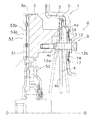
図1〜図3に示すプルタイプのダイヤフラムスプリング式クラッチカバー組立体1は、エンジンのフライホイール51に対してクラッチディスク組立体52の摩擦部材53を押し付けてクラッチを連結し、あるいは押し付けを解除してクラッチを切断するための装置である。なお、摩擦部材53は、摩擦フェーシング53aとクッショニングプレート53bとを有し、軸方向に所定範囲内でたわみ可能なクッショニング機能を有している。
(1) Overall Structure of Clutch Cover Assembly The pull type diaphragm spring type clutch cover assembly 1 shown in FIGS. 1 to 3 presses the friction member 53 of the clutch disc assembly 52 against the flywheel 51 of the engine. This is a device for disengaging the clutch by connecting or releasing the clutch. The friction member 53 includes a friction facing 53a and a cushioning plate 53b, and has a cushioning function that can be deflected within a predetermined range in the axial direction.

図1及び図2に示すO−O線が、フライホイール51及びクラッチカバー組立体1の回転軸線である。以下、図の左側を軸方向エンジン側といい、図の右側を軸方向トランスミッション側という。   The OO line shown in FIGS. 1 and 2 is the rotational axis of the flywheel 51 and the clutch cover assembly 1. Hereinafter, the left side of the figure is referred to as the axial engine side, and the right side of the figure is referred to as the axial transmission side.

クラッチカバー組立体1は、主に、クラッチカバー2と、プレッシャープレート3と、ダイヤフラムスプリング4とから構成されている。   The clutch cover assembly 1 is mainly composed of a clutch cover 2, a pressure plate 3, and a diaphragm spring 4.

クラッチカバー2は、概ね皿形状のプレート部材であり、外周部が例えばボルトによりフライホイール51に固定されている。クラッチカバー2は、フライホイール51の外周部に対して軸方向に隙間をあけて対向する円板状部分を有している。   The clutch cover 2 is a substantially dish-shaped plate member, and an outer peripheral portion thereof is fixed to the flywheel 51 by bolts, for example. The clutch cover 2 has a disk-shaped portion that faces the outer peripheral portion of the flywheel 51 with a gap in the axial direction.

プレッシャープレート3は、フライホイール51に対向する側に押圧面3aが形成された環状の部材である。押圧面3aとフライホイール51との間には、クラッチディスク組立体52の摩擦部材53が配置される。プレッシャープレート3には、押圧面3aと反対側に軸方向に突出する環状の突出部3bが形成されている。プレッシャープレート3は、複数のストラッププレート7によって、クラッチカバー2に対して、軸方向には移動可能であるが相対回転不能に連結されている。   The pressure plate 3 is an annular member having a pressing surface 3 a formed on the side facing the flywheel 51. Between the pressing surface 3a and the flywheel 51, the friction member 53 of the clutch disk assembly 52 is disposed. The pressure plate 3 is formed with an annular protrusion 3b that protrudes in the axial direction on the side opposite to the pressing surface 3a. The pressure plate 3 is connected to the clutch cover 2 by a plurality of strap plates 7 so as to be movable in the axial direction but not relatively rotatable.

ダイヤフラムスプリング4は、プレッシャープレート3とクラッチカバー2との間に配置された円板状部材であり、環状弾性部4aと、環状弾性部4aの内周部から径方向内側に延びる複数のレバー部4bとから構成されている。環状弾性部4aの内周部はプレッシャープレート3の突出部3bに当接している。環状弾性部4aの外周部はワイヤリング5を介してクラッチカバー2に支持されている。この状態で環状弾性部4aはプレッシャープレート3をフライホイール51側に付勢している。ダイヤフラムスプリング4のレバー部4b間はスリットになっており、そのスリットの外周部には小判状の孔4cが形成されている。ダイヤフラムスプリング4のレバー部4bの先端にはプルタイプのレリーズ装置(図示せず)が係合している。このレリーズ装置は、レリーズベアリング等から構成されている。   The diaphragm spring 4 is a disk-shaped member disposed between the pressure plate 3 and the clutch cover 2, and includes an annular elastic portion 4a and a plurality of lever portions extending radially inward from the inner peripheral portion of the annular elastic portion 4a. 4b. The inner peripheral portion of the annular elastic portion 4 a is in contact with the protruding portion 3 b of the pressure plate 3. The outer peripheral portion of the annular elastic portion 4 a is supported by the clutch cover 2 via the wire ring 5. In this state, the annular elastic portion 4a biases the pressure plate 3 toward the flywheel 51. A slit is formed between the lever portions 4b of the diaphragm spring 4, and an oval hole 4c is formed in the outer peripheral portion of the slit. A pull-type release device (not shown) is engaged with the tip of the lever portion 4 b of the diaphragm spring 4. This release device is composed of a release bearing or the like.

(2)第1低レリーズ荷重特性実現機構
次に、第1低レリーズ荷重特性実現機構8について説明する。第1低レリーズ荷重特性実現機構8は、押付荷重特性の平坦化を達成することで、摩擦部材53の摩耗が進んだ場合でも低レリーズ荷重特性を実現するための機構である。機構8は、円周方向に並んで配置された第1ユニット9と第2ユニット10とから構成されている。第1ユニット9と第2ユニット10はそれぞれ2つずつ設けられており、円周方向に交互に配置されている。このため、機構8は円周方向においてバランスよく荷重を発生する。
(2) First Low Release Load Characteristics Realizing Mechanism Next, the first low release load characteristics realizing mechanism 8 will be described. The first low release load characteristic realizing mechanism 8 is a mechanism for realizing a low release load characteristic even when wear of the friction member 53 progresses by achieving flattening of the pressing load characteristic. The mechanism 8 includes a first unit 9 and a second unit 10 that are arranged side by side in the circumferential direction. Two each of the first unit 9 and the second unit 10 are provided, and are arranged alternately in the circumferential direction. For this reason, the mechanism 8 generates a load in a balanced manner in the circumferential direction.

第1ユニット9は、図1に示すように、支持ボルト12と、スプリングシート13と、2枚のコーンスプリング14とから構成されている。支持ボルト12は、プレッシャープレート3の突出部3b側の面の内周部から軸方向トランスミッション側に延びている。支持ボルト12は、胴部12aと頭部12bを有している。支持ボルト12の胴部12aは、ダイヤフラムスプリング4の小判状の孔4cを通ってさらに軸方向に延びている。クラッチカバー2において、支持ボルト12に対応する位置には、孔16が形成されている。孔16は、小判状の孔4cより大きな円形状である。支持ボルト12の胴部12aは、孔16を通ってさらに軸方向に延びており、その結果支持ボルト12の頭部12bはクラッチカバー2より軸方向トランスミッション側に位置している。スプリングシート13は、ワッシャ状の部材であり、支持ボルト12の頭部12bの軸方向エンジン側の面に当接して配置されている。コーンスプリング14は、2枚のスプリングが並列に作用するように重ねて配置されており、クラッチカバー2において孔16の軸方向トランスミッション側に配置されている。各スプリングの組み合わせによって各ユニット9において好ましい荷重を発生できる。コーンスプリング14は、外周縁がクラッチカバー2の孔16の縁部分に支持されている。また、クラッチカバー2の孔16の周囲には、支持リング17が固定部材18によって固定されている。支持リング17は、コーンスプリング14の外周部の軸方向トランスミッション側に近接している。このため、コーンスプリング14の外周縁はクラッチカバー2に対して軸方向に大きく移動できないようになっている。コーンスプリング14の内周縁は、スプリングシート13に支持されている。クラッチ未摩耗段階ではクラッチ連結時において、コーンスプリング14は荷重を発生していない。一方、クラッチディスク組立体52の摩擦部材53が摩耗すると、プレッシャープレート3及び支持ボルト12が軸方向エンジン側に移動し、そのためコーンスプリング14はクラッチカバー2とスプリングシート13との間で圧縮され、両部材に対して軸方向に荷重を付与する。コーンスプリング14が支持ボルト12等に与える荷重は、ダイヤフラムスプリング4がプレッシャープレート3に付与する押付荷重と反対側に作用するものであり、押付荷重を低減させ、その結果レリーズ荷重も低く抑える効果を実現している(後述)。   As shown in FIG. 1, the first unit 9 includes a support bolt 12, a spring seat 13, and two cone springs 14. The support bolt 12 extends from the inner peripheral portion of the pressure plate 3 on the protruding portion 3b side to the axial transmission side. The support bolt 12 has a trunk portion 12a and a head portion 12b. The trunk portion 12 a of the support bolt 12 extends further in the axial direction through the oblong hole 4 c of the diaphragm spring 4. In the clutch cover 2, a hole 16 is formed at a position corresponding to the support bolt 12. The hole 16 has a circular shape larger than the oval hole 4c. The trunk portion 12 a of the support bolt 12 extends further in the axial direction through the hole 16, and as a result, the head portion 12 b of the support bolt 12 is located on the axial transmission side with respect to the clutch cover 2. The spring seat 13 is a washer-like member, and is disposed in contact with the surface on the axial direction engine side of the head 12 b of the support bolt 12. The cone spring 14 is arranged so that two springs act in parallel, and is arranged on the clutch cover 2 on the axial transmission side of the hole 16. A preferable load can be generated in each unit 9 by combining each spring. The cone spring 14 has an outer peripheral edge supported by an edge portion of the hole 16 of the clutch cover 2. A support ring 17 is fixed around the hole 16 of the clutch cover 2 by a fixing member 18. The support ring 17 is close to the axial transmission side of the outer peripheral portion of the cone spring 14. Therefore, the outer peripheral edge of the cone spring 14 cannot be moved greatly in the axial direction with respect to the clutch cover 2. The inner peripheral edge of the cone spring 14 is supported by the spring seat 13. When the clutch is not worn, the cone spring 14 does not generate a load when the clutch is engaged. On the other hand, when the friction member 53 of the clutch disk assembly 52 is worn, the pressure plate 3 and the support bolt 12 move to the axial engine side, so that the cone spring 14 is compressed between the clutch cover 2 and the spring seat 13, A load is applied to both members in the axial direction. The load applied by the cone spring 14 to the support bolt 12 or the like acts on the side opposite to the pressing load applied to the pressure plate 3 by the diaphragm spring 4, thereby reducing the pressing load and consequently reducing the release load. Realized (described later).

第2ユニット10は第1ユニット9と基本的な構造が同じである。ただし、図5に示すように、コーンスプリング14の内周縁とスプリングシート13との間に軸方向に隙間が確保されている。つまり、摩擦部材53の摩耗の初期段階では第2ユニット10のコーンスプリング14は荷重を発生しない。言い換えると、第2ユニット10のコーンスプリング14の圧縮開始タイミングは、第1ユニット9のコーンスプリング14の圧縮開始タイミングからずらされている。   The second unit 10 has the same basic structure as the first unit 9. However, as shown in FIG. 5, a gap is secured in the axial direction between the inner peripheral edge of the cone spring 14 and the spring seat 13. That is, the cone spring 14 of the second unit 10 does not generate a load at the initial stage of wear of the friction member 53. In other words, the compression start timing of the cone spring 14 of the second unit 10 is shifted from the compression start timing of the cone spring 14 of the first unit 9.

図6の押付荷重特性について説明する。ダイヤフラムスプリング4の特性20は、すでに説明したように山部分21を有している。それに対して、第1ユニット9のコーンスプリング14の特性22と第2ユニット10のコーンスプリング14の特性23はその部分21を打ち消す反対側の山部分(下に凸となる部分)を有しており、合成荷重平坦部24を形成している。さらに詳細には、第1ユニット9のコーンスプリング14は、セットライン25から荷重を発生しており、谷部分が摩耗代の端部に位置している。第2ユニット10のコーンスプリング14はセットライン25から幾分ずれてから荷重を発生しており、谷部分が摩耗代の端部から幾分ずれている。このように2種類のコーンスプリングを組み合わせて使用することによって、十分に大きい摩耗代を確保した合成荷重平坦部24を実現している。これにより、摩擦部材53が磨耗した時でも摩耗していないときに比べてクラッチペダル踏力がほとんど変化せず、レリーズ操作時の操作フィーリングが向上している。   The pressing load characteristic of FIG. 6 will be described. The characteristic 20 of the diaphragm spring 4 has a peak portion 21 as already described. On the other hand, the characteristic 22 of the cone spring 14 of the first unit 9 and the characteristic 23 of the cone spring 14 of the second unit 10 have opposite mountain portions (portions protruding downward) that cancel the portion 21. The composite load flat portion 24 is formed. More specifically, the cone spring 14 of the first unit 9 generates a load from the set line 25, and the valley portion is located at the end of the wear allowance. The cone spring 14 of the second unit 10 generates a load after being somewhat displaced from the set line 25, and the valley portion is somewhat displaced from the end of the wear allowance. As described above, the combined load flat portion 24 having a sufficiently large wear allowance is realized by using two types of cone springs in combination. Thereby, even when the friction member 53 is worn, the clutch pedal depressing force is hardly changed compared to when the friction member 53 is not worn, and the operation feeling during the release operation is improved.

(3)第2低レリーズ荷重特性実現機構
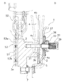
図2及び図3を用いて、第2低レリーズ荷重特性実現機構30について説明する。第2低レリーズ荷重特性実現機構30は、摩擦部材53におけるクッショニング機能による低レリーズ荷重化を、摩擦部材53が摩耗した状態でも実現するためのレリーズ補助用機構である。最初に、図9を用いて、摩擦部材におけるクッショニング機能による低レリーズ荷重化を説明する。クッショニング機能がない場合は、レリーズ荷重特性60は、ピークすなわち荷重バランス点63までは線形に変化し、そこからなだらかに小さくなっていき、またなだらかに大きくなっていく。また、荷重バランス点63まではプレッシャープレートの切れ量65はゼロである。摩擦部材がクッション機能を有している場合は、レリーズ時のプレッシャープレートの動きが早くなり、プレッシャープレートの切れ量65はクッショニングプレートがない場合に比べて早く大きくなる。また、図9において荷重バランス点63におけるピークが大幅に小さくなり、低レリーズ荷重特性が実現される。以上の結果が得られるのは、プレッシャープレートの位置がレリーズ動作中において、図6の押付荷重特性において負の勾配方向(右方向)に移動するからである。したがって、摩擦部材の摩耗によってセットラインの位置が変わればプレッシャープレートはレリーズ動作中において平坦部分や正勾配部分を移動することも考えられる。そこで、第2低レリーズ荷重特性実現機構30は、摩擦部材が摩耗した場合でも、プレッシャープレートが荷重特性の負の勾配方向に移動することを実現する。
(3) Second Low Release Load Characteristic Realization Mechanism The second low release load characteristic realization mechanism 30 will be described with reference to FIGS. 2 and 3. The second low release load characteristic realizing mechanism 30 is a release assisting mechanism for realizing the low release load by the cushioning function in the friction member 53 even when the friction member 53 is worn. First, the reduction in the release load by the cushioning function in the friction member will be described with reference to FIG. When there is no cushioning function, the release load characteristic 60 changes linearly up to the peak, that is, the load balance point 63, and gradually decreases and increases gradually. Further, the pressure plate breakage 65 is zero up to the load balance point 63. When the friction member has a cushion function, the pressure plate moves quickly at the time of release, and the pressure plate breakage amount 65 increases faster than when there is no cushioning plate. Further, the peak at the load balance point 63 in FIG. 9 is significantly reduced, and a low release load characteristic is realized. The above result is obtained because the position of the pressure plate moves in the negative gradient direction (right direction) in the pressing load characteristic of FIG. 6 during the release operation. Therefore, if the position of the set line changes due to wear of the friction member, the pressure plate may move in a flat portion or a positive gradient portion during the release operation. Therefore, the second low release load characteristic realizing mechanism 30 realizes that the pressure plate moves in the negative gradient direction of the load characteristic even when the friction member is worn.

第2低レリーズ荷重特性実現機構30は、第1低レリーズ荷重特性実現機構8の第1ユニット9と第2ユニット10と同一半径方向位置に交互に並んで配置されている。第2低レリーズ荷重特性実現機構30は合計4カ所に配置されている。各機構30は、図4に示すように、第2支持ボルト31と、ホルダー32と、第1支持部材33と、スナップリング34と、第2支持部材35と、一対の第1コーンスプリング36と、第2コーンスプリング37と、支持リング38とから構成されている。   The second low release load characteristic realizing mechanism 30 is alternately arranged in the same radial direction position as the first unit 9 and the second unit 10 of the first low release load characteristic realizing mechanism 8. The second low release load characteristic realizing mechanisms 30 are arranged in a total of four places. As shown in FIG. 4, each mechanism 30 includes a second support bolt 31, a holder 32, a first support member 33, a snap ring 34, a second support member 35, and a pair of first cone springs 36. The second cone spring 37 and the support ring 38 are included.

第2支持ボルト31は、プレッシャープレート3の突出部3b側の面から軸方向トランスミッション側に延びている。第2支持ボルト31は、胴部31a、ネジ部31b、頭部31cをこの順に有している。胴部31aは、ダイヤフラムスプリング4の小判状の孔4cを軸方向に貫通している。ネジ部31bは、表面にネジが螺旋状に形成された部分であり、クラッチカバー2に形成された孔11内に配置されている。孔11は概ね円形の形状を有している。頭部31cは軸方向に比較長く形成されており、その回りにはアジャストスプリング39が巻かれている(後述)。   The second support bolt 31 extends from the surface of the pressure plate 3 on the protruding portion 3b side to the axial transmission side. The second support bolt 31 has a trunk portion 31a, a screw portion 31b, and a head portion 31c in this order. The body portion 31a passes through the oval hole 4c of the diaphragm spring 4 in the axial direction. The screw part 31 b is a part in which a screw is formed in a spiral shape on the surface, and is disposed in the hole 11 formed in the clutch cover 2. The hole 11 has a substantially circular shape. The head portion 31c is formed longer in the axial direction, and an adjustment spring 39 is wound around the head portion 31c (described later).

ホルダー32は、筒状の部材であり、筒部32aとフランジ部32bとから構成されている。筒部32aの内周面には、ネジ部31bに螺合するネジ32dが形成されている。なお、図4の状態ではネジ部31bは、筒部32aより軸方向トランスミッション側にも形成されている。フランジ部32bは筒部32aの軸方向トランスミッション側端から外周側に延びている。フランジ部32bには軸方向に貫通する複数の孔32cが形成されている。   The holder 32 is a cylindrical member and includes a cylindrical portion 32a and a flange portion 32b. A screw 32d that is screwed into the screw portion 31b is formed on the inner peripheral surface of the cylindrical portion 32a. In addition, in the state of FIG. 4, the screw part 31b is also formed in the axial direction transmission side rather than the cylinder part 32a. The flange portion 32b extends from the axial transmission side end of the cylindrical portion 32a to the outer peripheral side. A plurality of holes 32c penetrating in the axial direction are formed in the flange portion 32b.

第1支持部材33は、筒状の部材であり、ホルダー32の外周に配置されている。ホルダー32の軸方向エンジン側の端部の外周面にはスナップリング34がはめられており、スナップリング34によって、第1支持部材33はホルダー32に対し、わずかな隙間を保って、軸方向に移動不能に保持されている。なお、第1支持部材33の内周面とホルダー32の外周面との間には半径方向隙間が確保されており、そのため両者は相対回転可能である。第2支持部材35は、筒状の部材であり、第1支持部材33の軸方向エンジン側部分の外周面にねじ又はかしめ等により堅く固定されている。以上に述べたように、ホルダー32と第1支持部材33と第2支持部材35は、軸方向に一体に動く1つの構造となっている。また、第1支持部材33は外周側に延びる環状突部33aを有しており、第2支持部材35は外周側に延びる環状突部35aを有している。   The first support member 33 is a cylindrical member and is disposed on the outer periphery of the holder 32. A snap ring 34 is fitted on the outer peripheral surface of the end of the holder 32 on the axial direction engine side, and the first support member 33 maintains a slight gap with respect to the holder 32 by the snap ring 34 in the axial direction. It is held immovable. In addition, a radial clearance is secured between the inner peripheral surface of the first support member 33 and the outer peripheral surface of the holder 32, so that both can rotate relative to each other. The second support member 35 is a cylindrical member, and is firmly fixed to the outer peripheral surface of the axial direction engine side portion of the first support member 33 by screws or caulking. As described above, the holder 32, the first support member 33, and the second support member 35 have one structure that moves integrally in the axial direction. The first support member 33 has an annular protrusion 33a extending to the outer peripheral side, and the second support member 35 has an annular protrusion 35a extending to the outer peripheral side.

一対の第1コーンスプリング36は並列に作用するように重ねて配置されており、内周縁が第1支持部材33の環状突部33aに軸方向エンジン側から当接しており、外周縁が支持リング38に軸方向トランスミッション側から当接している。支持リング38は、クラッチカバー2の孔11の回りの軸方向トランスミッション側に固定部材19によって固定されている。第2コーンスプリング37は、内周縁が第2支持部材35の環状突部35aに軸方向トランスミッション側から当接しており、外周縁が支持リング38に軸方向エンジン側から当接している。以上より、第1コーンスプリング36は、ホルダー32等からなる構造体に対して軸方向トランスミッション側への荷重を与えることが可能であり、第2コーンスプリング37はホルダー32等からなる構造体に対して軸方向エンジン側への荷重を与えることが可能である。コーンスプリング36,37は、クラッチ連結時にはホルダー32等にほとんど荷重を付与していないが、クラッチレリーズ動作中にはホルダー32等に軸方向トランスミッション側に荷重を与えて、レリーズ荷重を低下させる。つまり、第1コーンスプリング36の荷重が第2コーンスプリング37の荷重より大きいことになる。   The pair of first cone springs 36 are arranged so as to act in parallel, the inner peripheral edge is in contact with the annular protrusion 33a of the first support member 33 from the axial engine side, and the outer peripheral edge is a support ring. 38 abuts from the axial transmission side. The support ring 38 is fixed to the axial transmission side around the hole 11 of the clutch cover 2 by a fixing member 19. The second cone spring 37 is in contact with the annular protrusion 35a of the second support member 35 from the axial transmission side at the inner peripheral edge, and is in contact with the support ring 38 from the axial engine side at the outer peripheral edge. As described above, the first cone spring 36 can apply a load to the axial transmission side with respect to the structure including the holder 32 and the like, and the second cone spring 37 is applied to the structure including the holder 32 and the like. It is possible to apply a load to the axial engine side. The cone springs 36 and 37 hardly apply a load to the holder 32 and the like when the clutch is engaged, but apply a load to the holder 32 and the like on the axial transmission side during the clutch release operation to reduce the release load. That is, the load of the first cone spring 36 is larger than the load of the second cone spring 37.

コーンスプリング36,37は、クラッチカバー2の軸方向トランスミッション側に配置されているため、組み付けや取り外しが容易である。   Since the cone springs 36 and 37 are arranged on the side of the clutch cover 2 in the axial direction, assembly and removal are easy.

アジャストスプリング39は、捩りコイルスプリングであって、第2支持ボルト31の頭部31cに巻かれ、一端が頭部31cに係合している。さらに、アジャストスプリング39の係合端39aは、ホルダー32の孔32cに挿入され係合している。この結果、アジャストスプリング39は、ホルダー32を回転方向片側にほぼ一定の荷重を与えている。アジャストスプリング39からの荷重付与方向は、ホルダー32がネジ部31bに沿って軸方向トランスミッション側に移動していく方向である。   The adjustment spring 39 is a torsion coil spring, wound around the head portion 31c of the second support bolt 31, and has one end engaged with the head portion 31c. Further, the engagement end 39 a of the adjustment spring 39 is inserted into the hole 32 c of the holder 32 and engaged therewith. As a result, the adjustment spring 39 applies a substantially constant load to the holder 32 on one side in the rotational direction. The direction in which the load is applied from the adjustment spring 39 is a direction in which the holder 32 moves toward the axial transmission side along the screw portion 31b.

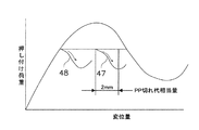
第2低レリーズ荷重特性実現機構30の動作について説明する。図7に示すように、第1コーンスプリング36の特性43は正側(軸方向トランスミッション側)に向けて荷重を発生するようになっており、第2コーンスプリング37の特性44は負側(軸方向エンジン側)に向けて荷重を発生するようになっている。第1コーンスプリング36の特性43は谷部と山部の差が大きくて勾配が大きく、第2コーンスプリング37の特性44は谷部と山部の差が小さくて勾配が小さい。合成特性45は、谷部がクラッチエンゲージ位置に配置され、そこでの荷重がゼロになっている。なお、合成特性45の谷荷重はゼロ以下になるように設計されることが好ましい。荷重ゼロから最大レリーズ位置側に移動すると、荷重は正側に徐々に大きくなっていく。これを図8のセット荷重特性でみると、摩擦部材53が摩耗した後にレリーズ動作を行うと、摩擦部材53におけるクッション機能によってセットラインが変位量大側にライン47,48のようにシフトする。つまり、押付特性において負勾配が必ず確保されており、したがってクッション機能による低レリーズ荷重化が確実に実現される。   The operation of the second low release load characteristic realizing mechanism 30 will be described. As shown in FIG. 7, the characteristic 43 of the first cone spring 36 generates a load toward the positive side (axial transmission side), and the characteristic 44 of the second cone spring 37 has a negative side (shaft). A load is generated toward the direction engine side). The characteristic 43 of the first cone spring 36 has a large difference between the valley and the peak and has a large gradient, and the characteristic 44 of the second cone spring 37 has a small difference between the valley and the peak and has a small gradient. In the composite characteristic 45, the valley portion is disposed at the clutch engagement position, and the load there is zero. The valley load of the composite characteristic 45 is preferably designed to be zero or less. When moving from zero load to the maximum release position, the load gradually increases to the positive side. In view of the set load characteristics shown in FIG. 8, when the release operation is performed after the friction member 53 is worn, the set line is shifted to the large displacement side like lines 47 and 48 by the cushion function in the friction member 53. In other words, a negative gradient is always ensured in the pressing characteristics, and therefore a low release load is reliably realized by the cushion function.

クラッチ連結状態では、アジャストスプリング39によりホルダー32を回転させる力(トルク)とコーンスプリング36及び37の合成荷重(軸方向荷重)によるねじ面の摩擦力とが釣り合っており、そのためこの状態で第2支持ボルト31にかかる軸方向荷重はゼロよりわずかに大きい値になっている。摩擦部材53が摩耗すると、第2支持ボルト31、ホルダー32等は軸方向エンジン側に移動する。すると、コーンスプリング36及び37の変形が進み、それら部材の荷重が低下しゼロになり、そのとき、アジャストスプリング39がホルダー32を回転させて軸方向エンジン側に移動させる。すると、コーンスプリング36及び37による軸方向の合成荷重が増加し、それに正比例してねじ面の摩擦力が増加するため、アジャストスプリング39のトルクによりホルダー32を回転させることが不可能になり、そこでホルダー32の軸方向移動が停止する。このように、摩擦部材53が摩耗しても、第2低レリーズ荷重特性実現機構30におけるコーンスプリング36,37の姿勢は、元の状態に復帰させられる。その結果、コーンスプリング36,37の姿勢は摩擦部材53が摩耗しても維持され、第2低レリーズ荷重特性実現機構30の荷重は一定に維持される。   In the clutch engaged state, the force (torque) for rotating the holder 32 by the adjustment spring 39 is balanced with the frictional force of the thread surface due to the combined load (axial load) of the cone springs 36 and 37. The axial load applied to the support bolt 31 is slightly larger than zero. When the friction member 53 is worn, the second support bolt 31, the holder 32, etc. move to the axial engine side. Then, the cone springs 36 and 37 are deformed, and the load of these members is reduced to zero. At that time, the adjustment spring 39 rotates the holder 32 and moves it to the axial engine side. Then, the combined load in the axial direction by the cone springs 36 and 37 increases, and the frictional force of the thread surface increases in direct proportion thereto. Therefore, it becomes impossible to rotate the holder 32 by the torque of the adjustment spring 39, The axial movement of the holder 32 stops. Thus, even if the friction member 53 is worn, the postures of the cone springs 36 and 37 in the second low release load characteristic realizing mechanism 30 are returned to the original state. As a result, the postures of the cone springs 36 and 37 are maintained even when the friction member 53 is worn, and the load of the second low release load characteristic realizing mechanism 30 is maintained constant.

(4)クラッチ連結・レリーズ動作
このクラッチカバー組立体1では、図示しないレリーズ装置がダイヤフラムスプリング4のレバー部4bの先端に荷重を与えていない状態で、環状弾性部4aはプレッシャープレート3に押圧荷重を与えている。その結果、クラッチディスク組立体52の摩擦部材53がフライホイール51に押し付けられ、クラッチディスク組立体52にトルクが伝達される(クラッチ連結状態)。
(4) Clutch connection / release operation In this clutch cover assembly 1, the annular elastic portion 4 a presses against the pressure plate 3 while a release device (not shown) does not apply a load to the tip of the lever portion 4 b of the diaphragm spring 4. Is given. As a result, the friction member 53 of the clutch disk assembly 52 is pressed against the flywheel 51, and torque is transmitted to the clutch disk assembly 52 (clutch engagement state).

図示しないレリーズ装置がダイヤフラムスプリング4のレバー部4bの先端をトランスミッション側に引き出すと、ワイヤリング5を支点としてダイヤフラムスプリング4の環状弾性部4aの内周部が軸方向トランスミッション側に引き上げられる。これにより、環状弾性部4aがプレッシャープレート3を押圧しなくなり、プレッシャープレート3はストラッププレート7により摩擦部材53から引き離され、最後に摩擦部材53がフライホイール51から離れる(クラッチ解除状態)。   When a release device (not shown) pulls out the tip of the lever portion 4b of the diaphragm spring 4 to the transmission side, the inner peripheral portion of the annular elastic portion 4a of the diaphragm spring 4 is lifted to the axial transmission side with the wire ring 5 as a fulcrum. Thereby, the annular elastic portion 4a does not press the pressure plate 3, the pressure plate 3 is pulled away from the friction member 53 by the strap plate 7, and finally the friction member 53 is separated from the flywheel 51 (clutch release state).

(5)第2低レリーズ荷重特性実現機構の別の実施事例
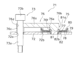
図10を用いて、第2低レリーズ荷重特性実現機構71を説明する。第2低レリーズ荷重特性実現機構71は、前記実施形態の機構30と同様の機能を実現するための機構であり、クラッチカバー72に設けられている。なお、図10はクラッチ連結状態を示している。
(5) Another Example of Second Low Release Load Characteristic Realization Mechanism The second low release load characteristic realization mechanism 71 will be described with reference to FIG. The second low release load characteristic realizing mechanism 71 is a mechanism for realizing the same function as the mechanism 30 of the above-described embodiment, and is provided on the clutch cover 72. FIG. 10 shows the clutch engaged state.

支持ボルト73は、前記実施形態と同様に、プレッシャープレートから軸方向トランスミッション側に延びている。支持ボルト73の胴部73aは、クラッチカバー72に形成された孔72aを貫通している。その結果、胴部73aの一部及び頭部73bはクラッチカバー72の軸方向トランスミッション側に位置している。   The support bolt 73 extends from the pressure plate to the axial transmission side as in the above embodiment. The body 73 a of the support bolt 73 passes through a hole 72 a formed in the clutch cover 72. As a result, a part of the trunk portion 73a and the head portion 73b are located on the axial transmission side of the clutch cover 72.

スプリングユニット75は、クラッチカバーに形成された円形状の孔72bの軸方向トランスミッション側に配置されている。スプリングユニット75は、支持ボルト73と概ね同一半径方向位置に配置されている。スプリングユニット75は、一対の第1コーンスプリング77と、第2コーンスプリング78と、スプリングシート79と、スナップリング80と、第1部材81と、第2部材82とから構成されている。スプリングシート79は、クラッチカバー72の孔72bの回りに着座した筒状の部材である。第1部材81と第2部材82は、孔72b内に配置され、互いにネジによって堅く固定されている。第1部材81は外周側に延びる環状の突部81aを有し、第2部材82は突部81aに対して軸方向に隙間をあけて対向する部分82bを有している。   The spring unit 75 is disposed on the transmission side in the axial direction of a circular hole 72b formed in the clutch cover. The spring unit 75 is disposed at substantially the same radial position as the support bolt 73. The spring unit 75 includes a pair of a first cone spring 77, a second cone spring 78, a spring seat 79, a snap ring 80, a first member 81, and a second member 82. The spring seat 79 is a cylindrical member seated around the hole 72 b of the clutch cover 72. The first member 81 and the second member 82 are disposed in the hole 72b and are firmly fixed to each other by screws. The first member 81 has an annular protrusion 81a extending to the outer peripheral side, and the second member 82 has a portion 82b facing the protrusion 81a with a gap in the axial direction.

第1コーンスプリング77と第2コーンスプリング78の内周縁は、第1部材81と第2部材82との空間内に配置されている。具体的には、第1コーンスプリング77の内周縁は、第1部材81の突部81aに対して軸方向エンジン側から当接している。第2コーンスプリング78の内周縁は、第2部材82の部分82bに軸方向エンジン側から当接している。第1コーンスプリング77と第2コーンスプリング78の外周縁は、スプリングシート79によって支持されている。具体的には、スプリングシート79の軸方向トランスミッション側端の内周面にはスナップリング80が固定され、コーンスプリング77,78の軸方向エンジン側への移動を制限している。第2コーンスプリング78の外周縁は、スプリングシート79の軸方向エンジン側に形成された内周側突出部79aに軸方向トランスミッション側から当接している。第1コーンスプリング77の外周縁と第2コーンスプリング78の外周縁との間には、ワイヤリングが配置されている。第1コーンスプリング77の外周縁とスナップリング80との間には、ワイヤリングが配置されている。以上より、第1コーンスプリング77は第1及び第2部材81,82からなる構造体に対して軸方向トランスミッション側への荷重を与えることが可能であり、第2コーンスプリング78は第1及び第2部材81,82からなる構造体に対して軸方向エンジン側への荷重を与えることが可能である。クラッチ連結時には、コーンスプリング77,78はアーム部材76にほとんど荷重を付与していないが、クラッチレリーズ動作中にはアーム部材76に軸方向トランスミッション側に荷重を与えて、レリーズ荷重を低下させる。つまり、第1コーンスプリング77の荷重が第2コーンスプリング78の荷重より大きいことになる。   The inner peripheral edges of the first cone spring 77 and the second cone spring 78 are disposed in the space between the first member 81 and the second member 82. Specifically, the inner peripheral edge of the first cone spring 77 is in contact with the protrusion 81a of the first member 81 from the axial engine side. The inner peripheral edge of the second cone spring 78 is in contact with the portion 82b of the second member 82 from the axial engine side. The outer peripheral edges of the first cone spring 77 and the second cone spring 78 are supported by a spring seat 79. Specifically, a snap ring 80 is fixed to the inner peripheral surface of the end of the spring seat 79 on the axial transmission side to limit the movement of the cone springs 77 and 78 toward the engine in the axial direction. The outer peripheral edge of the second cone spring 78 is in contact with an inner peripheral protrusion 79a formed on the axial engine side of the spring seat 79 from the axial transmission side. A wire ring is disposed between the outer peripheral edge of the first cone spring 77 and the outer peripheral edge of the second cone spring 78. A wire ring is arranged between the outer peripheral edge of the first cone spring 77 and the snap ring 80. As described above, the first cone spring 77 can apply a load to the axial transmission side with respect to the structure including the first and second members 81 and 82, and the second cone spring 78 has the first and second It is possible to apply a load on the axial engine side to the structure formed by the two members 81 and 82. When the clutch is engaged, the cone springs 77 and 78 hardly apply a load to the arm member 76, but during the clutch release operation, a load is applied to the arm member 76 toward the axial transmission side to reduce the release load. That is, the load of the first cone spring 77 is larger than the load of the second cone spring 78.

また、スプリングユニット75の荷重特性は、前記実施形態のコーンスプリング36及び37の合成荷重特性(図7)と同等であり、またコーンスプリングユニット75の構造も、前記実施形態と同様なものであっても良い。   The load characteristic of the spring unit 75 is equivalent to the combined load characteristic (FIG. 7) of the cone springs 36 and 37 of the above embodiment, and the structure of the cone spring unit 75 is the same as that of the above embodiment. May be.

アーム部材76は、支持ボルト73とスプリングユニット75とを連結させるための部材であり、本体部76aはクラッチカバー72に沿って延びている。本体部76aの一端には、第1係合部76bが形成されている。第1係合部76bは、本体部76aから軸方向エンジン側に延びる第1突出部76eと、その中心からさらに延びる第2突出部76fとから構成されている。第1突出部76eの端面は第1部材81の軸方向トランスミッション側面に当接しており、第2突出部76fは第1部材81の内側に入り込んでいる。本体部76aの他端には、第2係合部76cが形成されている。第2係合部76cは軸方向に延びる孔76dが形成されており、孔76dには支持ボルト73の胴部73aが摩擦係合している。ここでいう摩擦係合とは、所定荷重が作用するまでは固定状態であるが、所定荷重以上の荷重が作用すると滑りが生じることをいう。第2係合部76cは軸方向エンジン側に延びており、先端面がクラッチカバー72の孔72aの周囲の部分に当接している。   The arm member 76 is a member for connecting the support bolt 73 and the spring unit 75, and the main body 76 a extends along the clutch cover 72. A first engagement portion 76b is formed at one end of the main body portion 76a. The first engaging portion 76b includes a first protruding portion 76e extending from the main body portion 76a toward the axial engine side, and a second protruding portion 76f further extending from the center thereof. The end surface of the first protrusion 76 e is in contact with the axial transmission side surface of the first member 81, and the second protrusion 76 f enters the inside of the first member 81. A second engagement portion 76c is formed at the other end of the main body portion 76a. The second engaging portion 76c is formed with a hole 76d extending in the axial direction, and the body portion 73a of the support bolt 73 is frictionally engaged with the hole 76d. The frictional engagement here means a fixed state until a predetermined load is applied, but slipping occurs when a load greater than the predetermined load is applied. The second engaging portion 76 c extends toward the axial engine side, and the tip end surface is in contact with a portion around the hole 72 a of the clutch cover 72.

図10の状態からクラッチレリーズ動作を行うと、支持ボルト73及びアーム部材76が軸方向トランスミッション側に移動する。このとき、スプリングユニット75からアーム部材76に作用する荷重は徐々に大きくなっていく。以上より、低レリーズ荷重特性が得られる。なお、このとき、支持ボルト73と孔76dの摩擦係合部に対してスプリングユニット75からの荷重が作用するが、支持ボルト73と孔76dの間で滑りが生じない。その理由は、スプリングユニット75による荷重で孔76dがボルト73に対して傾き、孔76dの両端部に軸方向の移動を阻止する力が働く。アーム部76aの長さが孔76dの長さが孔76dの軸長に対して十分に長い場合は、そのロック荷重がスプリングユニット75の荷重を上回るため滑りを阻止することができる(いわゆるセルフロック現象)。。   When the clutch release operation is performed from the state shown in FIG. 10, the support bolt 73 and the arm member 76 move to the axial transmission side. At this time, the load acting on the arm member 76 from the spring unit 75 gradually increases. From the above, low release load characteristics can be obtained. At this time, the load from the spring unit 75 acts on the friction engagement portion between the support bolt 73 and the hole 76d, but no slip occurs between the support bolt 73 and the hole 76d. The reason is that the hole 76d is inclined with respect to the bolt 73 by the load of the spring unit 75, and a force that prevents the axial movement is applied to both ends of the hole 76d. When the length of the arm portion 76a is sufficiently long with respect to the axial length of the hole 76d, the lock load exceeds the load of the spring unit 75, so that slippage can be prevented (so-called self-locking). phenomenon). .

クラッチ連結状態で摩擦部材が摩耗すると、支持ボルト73はプレッシャープレートともに摩擦部材側に移動する。このときに、支持ボルト73と孔76dでは滑りが生じる。そのため、スプリングユニット75においてコーンスプリング77,78の姿勢は変化しない。つまり、摩擦部材の摩耗によって第2低レリーズ荷重特性実現機構71の荷重特性は変化しない。   When the friction member wears in the clutch engaged state, the support bolt 73 moves to the friction member side together with the pressure plate. At this time, slip occurs between the support bolt 73 and the hole 76d. Therefore, the postures of the cone springs 77 and 78 in the spring unit 75 do not change. That is, the load characteristic of the second low release load characteristic realizing mechanism 71 does not change due to wear of the friction member.

以上に述べたように、支持ボルト73とアーム部材76とからなる摩擦係合部において、クラッチ連結時に支持ボルト73に作用する抵抗をクラッチレリーズ時に支持ボルト73に作用する抵抗をより小さくしているため、第2低レリーズ荷重特性実現機構71の機能を維持したまま、プレッシャープレート3への押付荷重低減を防止できる。   As described above, in the friction engagement portion composed of the support bolt 73 and the arm member 76, the resistance acting on the support bolt 73 when the clutch is engaged is made smaller than the resistance acting on the support bolt 73 when the clutch is released. Therefore, it is possible to prevent the pressing load on the pressure plate 3 from being reduced while maintaining the function of the second low release load characteristic realizing mechanism 71.

前記実施形態は本発明の一実施例にすぎず、本発明の趣旨を逸脱しない範囲で様々な変更が可能である。例えば、前記実施形態はプルタイプのクラッチカバー組立体であるがプッシュタイプのクラッチカバー組立体にも本発明を適用できる。   The above embodiment is merely an example of the present invention, and various modifications can be made without departing from the spirit of the present invention. For example, the above embodiment is a pull type clutch cover assembly, but the present invention can also be applied to a push type clutch cover assembly.

第1低レリーズ荷重特性実現機構及び第2低レリーズ荷重特性実現機構の具体的な構造は変更可能であり、特に第1低レリーズ荷重特性実現機構は従来の1枚のコーンスプリングからなる構造であっても良い。   The specific structure of the first low release load characteristic realization mechanism and the second low release load characteristic realization mechanism can be changed, and in particular, the first low release load characteristic realization mechanism is a conventional one-piece cone spring structure. May be.

本発明の第1実施形態に係るクラッチカバー組立体の縦断面概略図。The longitudinal cross-sectional schematic of the clutch cover assembly which concerns on 1st Embodiment of this invention. 本発明の第1実施形態に係るクラッチカバー組立体の縦断面概略図。The longitudinal cross-sectional schematic of the clutch cover assembly which concerns on 1st Embodiment of this invention. 本発明の第1実施形態に係るクラッチカバー組立体の平面図。The top view of the clutch cover assembly which concerns on 1st Embodiment of this invention. 図2の部分拡大図であり、第2低レリーズ荷重特性実現機構を説明するための図。It is the elements on larger scale of Drawing 2, and is a figure for explaining the 2nd low release load characteristic realization mechanism. 第1低レリーズ荷重特性実現機構の第2ユニットの縦断面概略図。The longitudinal cross-sectional schematic of the 2nd unit of a 1st low release load characteristic implementation | achievement mechanism. 押付荷重特性を説明するための図。The figure for demonstrating the pressing load characteristic. 第2低レリーズ荷重特性実現機構の合成特性を説明するための図。The figure for demonstrating the synthetic | combination characteristic of a 2nd low release load characteristic implementation | achievement mechanism. セット荷重特性において、クッショニング機能が発揮されるときに得られる負勾配特性を説明するための図。The figure for demonstrating the negative gradient characteristic obtained when a cushioning function is exhibited in a set load characteristic. レリーズ荷重特性を説明するための図。The figure for demonstrating a release load characteristic. 第2低レリーズ荷重特性実現機構の別の実施事例の縦断面概略図。The longitudinal cross-sectional schematic of another implementation example of the 2nd low release load characteristic implementation | achievement mechanism.

符号の説明Explanation of symbols

1 クラッチカバー組立体
2 クラッチカバー
3 プレッシャープレート
4 ダイヤフラムスプリング
30 第2低レリーズ荷重特性実現機構
31 第2支持ボルト(支持部材)
32 ホルダー(支持係合部材)
36 第1コーンスプリング(第2弾性部材)
37 第2コーンスプリング(第2弾性部材)
39 アジャストスプリング(第3弾性部材)
51 フライホイール
52 クラッチディスク組立体
53 摩擦部材
DESCRIPTION OF SYMBOLS 1 Clutch cover assembly 2 Clutch cover 3 Pressure plate 4 Diaphragm spring 30 2nd low release load characteristic implementation mechanism 31 2nd support bolt (support member)
32 Holder (supporting engagement member)
36 First cone spring (second elastic member)
37 Second cone spring (second elastic member)
39 Adjustment spring (third elastic member)
51 Flywheel 52 Clutch Disc Assembly 53 Friction Member

Claims (10)

エンジンのフライホイールにクラッチディスク組立体のクッショニング機能付き摩擦部材を押し付け及び押し付け解除するためのクラッチカバー組立体であって、
前記フライホイールに固定されたクラッチカバーと、
前記クラッチカバーに対して相対回転不能に連結され、前記フライホイールとの間で前記摩擦部材を挟むためのプレッシャープレートと、
前記クラッチカバーに支持され、前記プレッシャープレートを前記フライホイール側に付勢するダイヤフラムスプリングと、
前記クラッチカバーに支持され、前記ダイヤフラムスプリングの付勢力に対抗する荷重を発生することで、前記ダイヤフラムスプリングの変位量に対する前記プレッシャープレートへの押付荷重の変化を平坦化するための第1弾性部材と、
前記クラッチカバーに支持され、レリーズ動作中に前記ダイヤフラムスプリングの付勢力に対抗する荷重を発生することで、前記摩擦部材のクッショニング機能によって前記ダイヤフラムスプリングの変位量が増大する過程において、前記プレッシャープレートへの押付荷重を減らしていく第2弾性部材と、
を備えたクラッチカバー組立体。
A clutch cover assembly for pressing and releasing a friction member with a cushioning function of a clutch disk assembly on an engine flywheel,
A clutch cover fixed to the flywheel;
A pressure plate connected to the clutch cover so as not to rotate relative to the clutch cover and sandwiching the friction member with the flywheel;
A diaphragm spring supported by the clutch cover and biasing the pressure plate toward the flywheel;
A first elastic member that is supported by the clutch cover and generates a load that opposes the urging force of the diaphragm spring, thereby flattening a change in the pressing load to the pressure plate with respect to a displacement amount of the diaphragm spring; ,
In the process in which the displacement amount of the diaphragm spring is increased by the cushioning function of the friction member by generating a load that is supported by the clutch cover and opposes the urging force of the diaphragm spring during the release operation. A second elastic member that reduces the pressing load of
A clutch cover assembly comprising:
前記第2弾性部材は、クラッチ連結状態からレリーズ動作が進むにつれて荷重を大きくしていく、請求項1に記載のクラッチカバー組立体。   2. The clutch cover assembly according to claim 1, wherein the second elastic member increases a load as a release operation proceeds from a clutch engaged state. 前記第2弾性部材は複数の弾性部材を組み合わせて構成されている、請求項1又は2に記載のクラッチカバー組立体。   The clutch cover assembly according to claim 1 or 2, wherein the second elastic member is configured by combining a plurality of elastic members. 前記第2弾性部材は前記クラッチカバーの前記摩擦部材側と軸方向反対側に配置されている、請求項1〜3のいずれかに記載のクラッチカバー組立体。   The clutch cover assembly according to any one of claims 1 to 3, wherein the second elastic member is disposed on an axially opposite side of the friction member side of the clutch cover. 前記プレッシャープレートから前記クラッチカバー側に延びる支持部材をさらに備え、
前記第2弾性部材は前記支持部材に対して前記摩擦部材側と軸方向反対側に荷重を付与する、請求項に記載のクラッチカバー組立体。
A support member extending from the pressure plate to the clutch cover side;
The clutch cover assembly according to claim 4 , wherein the second elastic member applies a load to the support member on an axially opposite side to the friction member side.
前記第2弾性部材はコーンスプリングである、請求項1〜5のいずれかに記載のクラッチカバー組立体。   The clutch cover assembly according to any one of claims 1 to 5, wherein the second elastic member is a cone spring. 前記摩擦部材の摩耗に対して前記第2弾性部材の姿勢を維持するための摩耗補償機構をさらに備えている、請求項1に記載のクラッチカバー組立体。   The clutch cover assembly according to claim 1, further comprising a wear compensation mechanism for maintaining the posture of the second elastic member with respect to wear of the friction member. 前記摩耗補償機構は、前記摩擦部材が摩耗したときに前記第2弾性部材を摩耗前の姿勢に復帰させるための復帰機構を有している、請求項7に記載のクラッチカバー組立体。   The clutch cover assembly according to claim 7, wherein the wear compensation mechanism has a return mechanism for returning the second elastic member to a posture before wear when the friction member is worn. 前記復帰機構は、前記プレッシャープレートから前記クラッチカバー側に延びる支持部材と、前記支持部材に対して係合して前記第2弾性部材から前記摩擦部材側と軸方向反対側に荷重を受ける支持係合部材と、前記支持部材に対してねじで係合して前記第2弾性部材から前記摩擦部材側と軸方向反対側に荷重を受ける支持係合部材と、前記支持係合部材が前記摩擦部材側と軸方向反対側に移動する方向に回転するよう前記支持係合部材に常時トルクを付与する第3弾性部材とを有する、請求項8に記載のクラッチカバー組立体。 The return mechanism includes a support member that extends from the pressure plate toward the clutch cover, and a support member that engages with the support member and receives a load from the second elastic member toward the friction member side in the axial direction. A combination member, a support engagement member that engages with the support member with a screw and receives a load from the second elastic member on the opposite side to the friction member side, and the support engagement member is the friction member and a third elastic member for applying a constant torque to the support and engagement member to rotate in a direction to move to the side axially opposite the clutch cover assembly according to claim 8. 前記摩耗補償機構は、前記第2弾性部材と異なる位置で前記プレッシャープレートから前記クラッチカバー側に延びる支持部材と、前記支持部材に摩擦係合して前記第2弾性部材から荷重を付与される摩擦係合部材とを有している、請求項7に記載のクラッチカバー組立体。   The wear compensation mechanism includes a support member that extends from the pressure plate to the clutch cover side at a position different from the second elastic member, and friction that is frictionally engaged with the support member and applied with a load from the second elastic member. The clutch cover assembly according to claim 7, further comprising an engaging member.
JP2004224343A 2004-07-30 2004-07-30 Clutch cover assembly Expired - Fee Related JP4414835B2 (en)

Priority Applications (1)

Application Number Priority Date Filing Date Title
JP2004224343A JP4414835B2 (en) 2004-07-30 2004-07-30 Clutch cover assembly

Applications Claiming Priority (1)

Application Number Priority Date Filing Date Title
JP2004224343A JP4414835B2 (en) 2004-07-30 2004-07-30 Clutch cover assembly

Publications (3)

Publication Number Publication Date
JP2006046368A JP2006046368A (en) 2006-02-16
JP2006046368A5 JP2006046368A5 (en) 2007-06-07
JP4414835B2 true JP4414835B2 (en) 2010-02-10

Family

ID=36025190

Family Applications (1)

Application Number Title Priority Date Filing Date
JP2004224343A Expired - Fee Related JP4414835B2 (en) 2004-07-30 2004-07-30 Clutch cover assembly

Country Status (1)

Country Link
JP (1) JP4414835B2 (en)

Families Citing this family (4)

* Cited by examiner, † Cited by third party
Publication number Priority date Publication date Assignee Title
US7607524B2 (en) * 2005-12-09 2009-10-27 Exedy Corporation Clutch cover assembly
JP4576327B2 (en) * 2005-12-09 2010-11-04 株式会社エクセディ Clutch cover assembly
JP4667222B2 (en) * 2005-12-09 2011-04-06 株式会社エクセディ Clutch cover assembly
WO2014005824A1 (en) * 2012-07-03 2014-01-09 Schaeffler Technologies AG & Co. KG Lever system

Also Published As

Publication number Publication date
JP2006046368A (en) 2006-02-16

Similar Documents

Publication Publication Date Title
JP4173509B2 (en) Clutch cover assembly
JP4667222B2 (en) Clutch cover assembly
JP5974450B2 (en) Clutch device
WO2008059699A1 (en) Clutch cover assembly
JP2000205297A (en) Automatically regulated friction clutch with protecting function against excessive regulation
JPH0861389A (en) Clutch pressing assembly body
JP4414835B2 (en) Clutch cover assembly
JP3943950B2 (en) Clutch cover assembly
WO2012039202A1 (en) Clutch cover assembly
JP4620403B2 (en) Clutch cover assembly
JP4535846B2 (en) Clutch cover assembly
JP2007198507A (en) Clutch cover assembly
JP5008757B2 (en) Clutch cover assembly
JP4576327B2 (en) Clutch cover assembly
EP1630438B1 (en) Clutch device for vehicle
US5906257A (en) Clutch cover assembly
US7607524B2 (en) Clutch cover assembly
JP4714592B2 (en) Clutch cover assembly
JP4754958B2 (en) Clutch cover assembly
JP2006132665A (en) Clutch cover assembly
JP4943012B2 (en) Clutch cover assembly
JP6870504B2 (en) Power transmission mechanism
JP2007198452A (en) Clutch cover assembly
JPS5929157Y2 (en) Friction clutch release assister
JP2591507Y2 (en) Clutch cover assembly

Legal Events

Date Code Title Description
A521 Request for written amendment filed

Free format text: JAPANESE INTERMEDIATE CODE: A523

Effective date: 20070418

A621 Written request for application examination

Free format text: JAPANESE INTERMEDIATE CODE: A621

Effective date: 20070418

A977 Report on retrieval

Free format text: JAPANESE INTERMEDIATE CODE: A971007

Effective date: 20091026

TRDD Decision of grant or rejection written
A01 Written decision to grant a patent or to grant a registration (utility model)

Free format text: JAPANESE INTERMEDIATE CODE: A01

Effective date: 20091104

A01 Written decision to grant a patent or to grant a registration (utility model)

Free format text: JAPANESE INTERMEDIATE CODE: A01

A61 First payment of annual fees (during grant procedure)

Free format text: JAPANESE INTERMEDIATE CODE: A61

Effective date: 20091120

FPAY Renewal fee payment (event date is renewal date of database)

Free format text: PAYMENT UNTIL: 20121127

Year of fee payment: 3

R150 Certificate of patent or registration of utility model

Ref document number: 4414835

Country of ref document: JP

Free format text: JAPANESE INTERMEDIATE CODE: R150

Free format text: JAPANESE INTERMEDIATE CODE: R150

FPAY Renewal fee payment (event date is renewal date of database)

Free format text: PAYMENT UNTIL: 20121127

Year of fee payment: 3

FPAY Renewal fee payment (event date is renewal date of database)

Free format text: PAYMENT UNTIL: 20151127

Year of fee payment: 6

R250 Receipt of annual fees

Free format text: JAPANESE INTERMEDIATE CODE: R250

R250 Receipt of annual fees

Free format text: JAPANESE INTERMEDIATE CODE: R250

R250 Receipt of annual fees

Free format text: JAPANESE INTERMEDIATE CODE: R250

LAPS Cancellation because of no payment of annual fees