JP4414662B2 - Closely wound coil and medical treatment tool using the closely wound coil - Google Patents
Closely wound coil and medical treatment tool using the closely wound coil Download PDFInfo
- Publication number
- JP4414662B2 JP4414662B2 JP2003056215A JP2003056215A JP4414662B2 JP 4414662 B2 JP4414662 B2 JP 4414662B2 JP 2003056215 A JP2003056215 A JP 2003056215A JP 2003056215 A JP2003056215 A JP 2003056215A JP 4414662 B2 JP4414662 B2 JP 4414662B2
- Authority
- JP
- Japan
- Prior art keywords
- axis
- wound coil
- strand
- cross
- section
- Prior art date
- Legal status (The legal status is an assumption and is not a legal conclusion. Google has not performed a legal analysis and makes no representation as to the accuracy of the status listed.)
- Expired - Fee Related
Links
Images


Classifications
-
- F—MECHANICAL ENGINEERING; LIGHTING; HEATING; WEAPONS; BLASTING
- F16—ENGINEERING ELEMENTS AND UNITS; GENERAL MEASURES FOR PRODUCING AND MAINTAINING EFFECTIVE FUNCTIONING OF MACHINES OR INSTALLATIONS; THERMAL INSULATION IN GENERAL
- F16C—SHAFTS; FLEXIBLE SHAFTS; ELEMENTS OR CRANKSHAFT MECHANISMS; ROTARY BODIES OTHER THAN GEARING ELEMENTS; BEARINGS
- F16C1/00—Flexible shafts; Mechanical means for transmitting movement in a flexible sheathing
- F16C1/02—Flexible shafts; Mechanical means for transmitting movement in a flexible sheathing for conveying rotary movements
-
- A—HUMAN NECESSITIES
- A61—MEDICAL OR VETERINARY SCIENCE; HYGIENE
- A61B—DIAGNOSIS; SURGERY; IDENTIFICATION
- A61B17/00—Surgical instruments, devices or methods, e.g. tourniquets
- A61B17/00234—Surgical instruments, devices or methods, e.g. tourniquets for minimally invasive surgery
-
- A—HUMAN NECESSITIES
- A61—MEDICAL OR VETERINARY SCIENCE; HYGIENE
- A61B—DIAGNOSIS; SURGERY; IDENTIFICATION
- A61B17/00—Surgical instruments, devices or methods, e.g. tourniquets
- A61B17/10—Surgical instruments, devices or methods, e.g. tourniquets for applying or removing wound clamps, e.g. containing only one clamp or staple; Wound clamp magazines
-
- A—HUMAN NECESSITIES
- A61—MEDICAL OR VETERINARY SCIENCE; HYGIENE
- A61B—DIAGNOSIS; SURGERY; IDENTIFICATION
- A61B17/00—Surgical instruments, devices or methods, e.g. tourniquets
- A61B17/32—Surgical cutting instruments
- A61B17/320016—Endoscopic cutting instruments, e.g. arthroscopes, resectoscopes
-
- A—HUMAN NECESSITIES
- A61—MEDICAL OR VETERINARY SCIENCE; HYGIENE
- A61B—DIAGNOSIS; SURGERY; IDENTIFICATION
- A61B17/00—Surgical instruments, devices or methods, e.g. tourniquets
- A61B17/12—Surgical instruments, devices or methods, e.g. tourniquets for ligaturing or otherwise compressing tubular parts of the body, e.g. blood vessels, umbilical cord
- A61B17/128—Surgical instruments, devices or methods, e.g. tourniquets for ligaturing or otherwise compressing tubular parts of the body, e.g. blood vessels, umbilical cord for applying or removing clamps or clips
- A61B17/1285—Surgical instruments, devices or methods, e.g. tourniquets for ligaturing or otherwise compressing tubular parts of the body, e.g. blood vessels, umbilical cord for applying or removing clamps or clips for minimally invasive surgery
-
- A—HUMAN NECESSITIES
- A61—MEDICAL OR VETERINARY SCIENCE; HYGIENE
- A61B—DIAGNOSIS; SURGERY; IDENTIFICATION
- A61B17/00—Surgical instruments, devices or methods, e.g. tourniquets
- A61B17/32—Surgical cutting instruments
- A61B17/3205—Excision instruments
- A61B17/32056—Surgical snare instruments
-
- A—HUMAN NECESSITIES
- A61—MEDICAL OR VETERINARY SCIENCE; HYGIENE
- A61B—DIAGNOSIS; SURGERY; IDENTIFICATION
- A61B18/00—Surgical instruments, devices or methods for transferring non-mechanical forms of energy to or from the body
- A61B18/04—Surgical instruments, devices or methods for transferring non-mechanical forms of energy to or from the body by heating
- A61B18/12—Surgical instruments, devices or methods for transferring non-mechanical forms of energy to or from the body by heating by passing a current through the tissue to be heated, e.g. high-frequency current
- A61B18/14—Probes or electrodes therefor
- A61B18/1492—Probes or electrodes therefor having a flexible, catheter-like structure, e.g. for heart ablation
-
- A—HUMAN NECESSITIES
- A61—MEDICAL OR VETERINARY SCIENCE; HYGIENE
- A61B—DIAGNOSIS; SURGERY; IDENTIFICATION
- A61B17/00—Surgical instruments, devices or methods, e.g. tourniquets
- A61B17/28—Surgical forceps
- A61B17/29—Forceps for use in minimally invasive surgery
- A61B2017/2901—Details of shaft
- A61B2017/2905—Details of shaft flexible
-
- A—HUMAN NECESSITIES
- A61—MEDICAL OR VETERINARY SCIENCE; HYGIENE
- A61B—DIAGNOSIS; SURGERY; IDENTIFICATION
- A61B18/00—Surgical instruments, devices or methods for transferring non-mechanical forms of energy to or from the body
- A61B18/04—Surgical instruments, devices or methods for transferring non-mechanical forms of energy to or from the body by heating
- A61B18/12—Surgical instruments, devices or methods for transferring non-mechanical forms of energy to or from the body by heating by passing a current through the tissue to be heated, e.g. high-frequency current
- A61B18/14—Probes or electrodes therefor
- A61B2018/1405—Electrodes having a specific shape
- A61B2018/1407—Loop
-
- F—MECHANICAL ENGINEERING; LIGHTING; HEATING; WEAPONS; BLASTING
- F16—ENGINEERING ELEMENTS AND UNITS; GENERAL MEASURES FOR PRODUCING AND MAINTAINING EFFECTIVE FUNCTIONING OF MACHINES OR INSTALLATIONS; THERMAL INSULATION IN GENERAL
- F16C—SHAFTS; FLEXIBLE SHAFTS; ELEMENTS OR CRANKSHAFT MECHANISMS; ROTARY BODIES OTHER THAN GEARING ELEMENTS; BEARINGS
- F16C2316/00—Apparatus in health or amusement
- F16C2316/10—Apparatus in health or amusement in medical appliances, e.g. in diagnosis, dentistry, instruments, prostheses, medical imaging appliances
Description
【0001】
【発明の属する技術分野】
本発明は、素線を所定の長さにわたって螺旋状に密に巻回することにより形成される密巻コイル及びこの密巻コイルを用いた医療用処置具に関する。
【0002】
【従来の技術】
内視鏡のチャンネルを通じて体内に導入される医療用処置具は、概して、先端に設けられた処置部と、手元側基端部に設けられた操作部と、前記操作部の操作力を前記処置部に伝達する力伝達部材とを備えている。
【0003】
前記力伝達部材は、体内の曲がりくねった管腔内に導入される内視鏡の長いチャンネル内に挿通されることから、屈曲や圧縮等に耐え、なおかつ、前記操作部側からの操作力を確実に前記処置部に伝達することが要求される。
【0004】
そのため、断面が円形の素線を所定の長さにわたって螺旋状に密に巻回することにより形成される密巻コイルが、前記力伝達部材として広く用いられている(例えば、特許文献1参照)。
【0005】
そのような密巻コイルを力伝達部材として備える医療用処置具の従来例が図42に示されている。図示のように、この医療用処置具100は、先端に設けられた処置部102と、手元側基端部に設けられた操作部106と、操作部106と処置部102とを接続する密巻コイル104とを備えている。また、医療用処置具100を体内に導入するための内視鏡200は、体内の管腔内などに挿入される挿入部202と手元側操作部206とを備えており、挿入部202内には、医療用処置具100を挿通するためのチャンネル208が形成されている。また、挿入部202の先端には、操作部206に設けられた操作ノブ(図示せず)によって湾曲操作される湾曲部204が設けられている。
【0006】
【特許文献1】
特開昭56−112221号公報
【0007】
【発明が解決しようとする課題】
ところで、従来の密巻コイルにおいては、1つの大きな課題が存在する。すなわち、図42に示されるように、内視鏡200が例えば体内の曲がりくねった管腔内に導入されて、内視鏡200の挿入部202が複雑に屈曲していると、挿入部202のチャンネル208内に挿通される医療用処置具100の密巻コイル104も長い距離にわたって複雑に屈曲してしまうが、この時、例えば処置部102の姿勢を変更すべく、操作部106を回転させて、その回転力を密巻コイル104を介して処置部102に伝達しようとしても、密巻コイル104に伴う様々な要因により、処置部102が思い通りに回転しない場合がある。特に湾曲部204が鋭い角度で湾曲している状態では、湾曲部204の先にある処置部102に対して回転力をリニアに伝達することが非常に難しくなる。
【0008】
図42に示されるような屈曲状態における従来の密巻コイルの回転伝達性能が、図43に概略的に示されている。図43に実線で示されるように、従来の密巻コイルでは、図42に示されるような屈曲状態で操作部106を回転させても、密巻コイル104の回転に遅れや飛び(ムラ)が発生して、処置部102が操作部106の回転にうまく追従できない。すなわち、図43に破線で示されるように、操作部106の回転角度(入力角度)がそのまま処置部102の回転角度(出力角度)となって現われること(入力角度=出力角度)が理想的ではあるが、現実には、図43に実線で示されるように、密巻コイル104の回転遅れや回転飛び等に起因して、入力角度と出力角度との間に遅れ等が生じ(入力角度−遅れ角度=出力角度)、回転出力が一定せず、狙った回転角度への微調整がし難い。
【0009】
本発明は前記事情に着目してなされたものであり、その目的とするところは、良好な回転伝達性能を有する密巻コイル及びこの密巻コイルを用いた医療用処置具を提供することにある。
【0011】
【課題を解決するための手段】
前記課題を解決するために、請求項1に記載された発明は、素線を所定の第1の軸を中心に所定の長さにわたって螺旋状に密に巻回することによって形成される密巻コイルにおいて、前記素線の素線軸に対して垂直な断面は、この断面の中心を通り且つ前記第1の軸と垂直な第2の軸と、前記断面の中心を通り且つ前記第2の軸に対して垂直で前記第1の軸と平行な第3の軸とを有し、 前記素線の曲げ剛性は、前記第2の軸または前記第3の軸に沿う前記素線の断面寸法のうち最も長い寸法を直径とする真円を断面形状とする基準素線の曲げ剛性と略同じであり、前記素線の捩じり剛性は、前記基準素線の捩じり剛性以下であることを特徴とする。
【0013】
また、請求項2に記載された発明は、素線を所定の第1の軸を中心に所定の長さにわたって螺旋状に密に巻回することによって形成される密巻コイルにおいて、前記素線の素線軸に対して垂直な断面は、この断面の中心を通り且つ前記第1の軸と垂直な第2の軸に沿う寸法が、前記断面の中心を通り且つ前記第2の軸に対して垂直で前記第1の軸に平行な第3の軸に沿う寸法よりも大きく、前記素線は、その捩じり剛性が、所定の直径の真円を断面形状とする素線のそれと略同一になるように、前記断面の寸法を設定した時に、第3の軸に関する曲げ剛性が真円を断面形状とする素線の曲げ剛性よりも大きいことを特徴とする。
【0014】
また、請求項3に記載された発明は、素線を所定の第1の軸を中心に所定の長さにわたって螺旋状に密に巻回することによって形成される密巻コイルにおいて、前記素線の素線軸に対して垂直な断面は、この断面の中心を通り且つ前記第1の軸と垂直な第2の軸に沿う寸法が、前記断面の中心を通り且つ前記第2の軸に対して垂直で前記第1の軸に平行な第3の軸に沿う寸法よりも大きく、前記素線は、第3の軸に関する曲げ剛性が、所定の直径の真円を断面形状とする素線のそれと略同一になるように、前記断面の寸法を設定した時に、捩じり剛性が真円を断面形状とする素線の捩じり剛性よりも小さいことを特徴とする。
また、請求項4に記載された発明は、請求項1ないし請求項3のいずれか1項に記載された発明において、前記素線の表面には、前記第2の軸に対して平行で、かつ、前記第3の軸に対して垂直な2つの平面が設けられ、前記平面で前記素線同士が接触していることを特徴とする。
また、請求項5に記載された発明は、複数の素線を径方向に重ねて形成される素線組を所定の第1の軸を中心に所定の長さにわたって螺旋状に密に巻回することによって形成される密巻コイルにおいて、 前記素線組の素線軸に対して垂直な断面は、この断面の中心を通り且つ前記第1の軸と垂直な第2の軸に沿う寸法が、前記断面の中心を通り且つ前記第2の軸に対して垂直で前記第1の軸に平行な第3の軸に沿う寸法よりも大きいことを特徴とする。
【0015】
また、請求項6に記載された医療用処置具は、請求項1ないし請求項3のいずれか1項に記載の密巻コイルと、 前記密巻コイルの基端に設けられ、前記密巻コイルをその第1の軸を中心に回転操作するための回転操作手段と、 前記密巻コイルよりも先端側に位置し、前記回転操作手段による回転操作力を前記密巻コイルを介して受ける処置部とを具備することを特徴とする。
【0016】
【発明の実施の形態】
本発明の具体的な実施形態について説明する前に、まず、本発明の基本的な概念ついて説明する。
【0017】
従来の密巻コイルにおいて、入力角度と出力角度との間に遅れ等を生じさせる(図43参照)原因は主に2つある。
【0018】
その原因の1つ目は、密巻コイルが剛体ではないことに伴う密巻コイルの捩じり変形による応力の蓄積である。すなわち、密巻コイルの一端に回転力が入力された際に、密巻コイルが捩じり変形を起こすと、回転力の一部が内部応力として密巻コイルに蓄積されることから、密巻コイルの他端で出力される回転角度は、密巻コイルの一端で入力された回転角度と一致しなくなる。したがって、密巻コイルの捩じり剛性が大きい場合には、密巻コイルにおける応力の蓄積が小さいため、回転に遅れや飛びが発生しにくく、したがって、回転伝達性能が高い。これに対し、密巻コイルの捩じり剛性が小さい場合には、密巻コイルにおける応力の蓄積が大きくなるため、回転に遅れや飛びが発生し易く、したがって、回転伝達性能が悪くなる。
【0019】
また、入力角度と出力角度との間に遅れ等を生じさせる2つ目の原因は、内視鏡のチャンネルと密巻コイルとの間に生じる摩擦抵抗である。すなわち、図1に示されるように、複雑に屈曲した内視鏡のチャンネル2内に密巻コイル4が挿通された状態では、屈曲部付近に位置する複数の各部Pで密巻コイル4がチャンネル2の内面に圧接され、これによって、摩擦抵抗が発生する。この場合、密巻コイル4の曲げ剛性が小さい場合には、屈曲する密巻コイル4とチャンネル2との接触点Pにおける面圧が小さくなるため、摩擦抵抗も小さくなる。しかしながら、密巻コイル4の曲げ剛性が大きい場合には、屈曲する密巻コイル4とチャンネル2との接触点Pにおける面圧も大きくなるため、摩擦抵抗も大きくなる。
【0020】
以上の2つの原因を考慮すると、密巻コイルの回転伝達性能を向上させるためには、密巻コイルの捩じり変形による応力の蓄積を減らし、また、内視鏡のチャンネルと密巻コイルとの間に生じる摩擦抵抗を小さくすることが必要である。すなわち、密巻コイルの捩じり剛性を大きくして、密巻コイルの曲げ剛性を小さくすれば、密巻コイルの回転伝達性能を向上させることができる。
【0021】
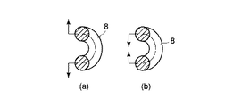
ところで、密巻コイルの捩じり剛性および曲げ剛性は、そもそも、密巻コイルを形成する素線の曲げ剛性および捩じり剛性にそれぞれ対応していると考えることができる。 すなわち、図2に示されるように、円形断面の素線8を所定の長さにわたって螺旋状に密に巻回することによって形成される密巻コイル10を考えると、密巻コイル10の捩じりは、図3に示されるように、素線8の曲げに相当している。具体的には、密巻コイル10をその巻き方向に捩じると、曲がり梁を形成する素線8の部位は、図3の(b)に示されるように内側に向けて曲げられ、逆に、密巻コイル10をその巻き方向と反対の方向に捩じると、曲がり梁を形成する素線8の部位は、図3の(a)に示されるように外側に向けて曲げられるようになる。したがって、密巻コイル10の捩じり剛性は、密巻コイル10を形成する素線8の曲げ剛性に対応すると言える。
【0022】
一方、密巻コイル10の曲げは、図4に示されるように、素線8の捩じりに相当する。なぜなら、密巻コイル10を曲げると、素線8は、その隣り合う巻回部分同士が互いに離れるように変形し、捩じり方向の力を受けるからである。したがって、密巻コイル10の曲げ剛性は、密巻コイル10を形成する素線8の捩じり剛性に相当すると言える。なお、図4の(b)は、図4の(a)に示されるように素線8に捩じりトルクが作用した時の素線8における応力分布を示している。
【0023】
以上の点をまとめると、密巻コイル10の回転伝達性能を向上させるためには、密巻コイル10の捩じり剛性を大きくし、また、密巻コイル10の曲げ剛性を小さくすることが必要であり、そのためには、密巻コイル10を形成する素線8の曲げ剛性を大きくし、また、素線8の捩じり剛性を小さくすることが必要となる。
【0024】
しかしながら、従来の密巻コイル10は、この条件を簡単に満たすことができない。なぜなら、従来の密巻コイル10は、素線8の断面形状が円形であることから、密巻コイル10の捩じり剛性を向上させるべく素線8の外径を大きくすると、それに伴って、密巻コイル10の曲げ剛性も大きくなってしまうからである。したがって、素線8が円形断面の場合には、外径寸法を単に変化させるだけで、密巻コイル10の回転性能を向上させることは難しい。
【0025】
本発明者は、以上説明した全ての点を熟慮し、結果として、ある一定の条件下で、素線における断面2次モーメントの相互関係が前記条件に大きく関与してくることを知見した。また、ある一定の条件の下では、素線が円形断面であっても、前記条件を簡単に満たすことができることを知見した。
【0026】
以下では、このような知見(本発明の概念)に基づく具体的な実施形態について説明する。
【0027】
図5〜図7は本発明の第1の実施形態を示している。
【0028】
図5に示されるように、本実施形態の密巻コイル20は、素線18を所定の第1の軸O1を中心に所定の長さにわたって螺旋状に密に巻回することによって形成されている。素線18は、その素線軸O2に対して垂直な断面Sにおいて、断面Sの中心O2を通り且つ第1の軸O1と垂直な第2の軸O3に関する断面2次モーメントI1が、断面Sの中心O2を通り且つ第2の軸O3に対して垂直な第3の軸O4に関する断面2次モーメントI2よりも小さくなるように形成されている。具体的には、素線18の断面Sは、第2の軸O3に沿う寸法Yが第3の軸O4に沿う寸法Xよりも大きい略矩形状を成しており(断面Sの縦/横比が1よりも大きく、第2の軸O3に沿う両端に曲率の大きい円弧を有している)、いわば、素線18の隣り合う巻回部分の断面S同士がその短径方向で密接するような配列状態(図5の状態)を成して密巻コイル20が形成されている。素線18のこのような断面形状は、例えば、円形断面の素線を第3の軸O4に沿う方向で圧延することにより低コストで形成される。
【0029】
また、本実施形態において、素線18は、その捩じり剛性が、直径dの真円を断面形状とする素線(以下、これを第1の基準素線という)のそれと同等(略同一)になるように、その断面Sの寸法が設定されている。具体的には、素線18を縦寸法Yおよび横寸法Xの矩形形状に近似して考えると、Y,Xとdとの関係が、
d=(32ξ1YX3/π)1/4 …(1)
となるように設定されている。
【0030】
ここで、ξ1はY/Xによって決定される定数である。
【0031】
因みに、式(1)は、以下のように導出される。
【0032】
すなわち、長さLの棒にTの捩じりモーメントを加えた時のねじれ角φは、
(i)円形断面の時、
φR=32TL/πd4G (Gは横弾性係数(材質により決まる定数))
であり、
(ii)矩形断面の時、
φL=TL/ξ1YX3G (Y>X)
であり、
捩じり剛性が同等であるということは、同じ捩じりモーメントを加えた時のねじれ角(変形量)が同じであるということであるから、
φR=φL
となり、したがって、
32TL/πd4G=TL/ξ1YX3G
となり、その結果、
d=(32ξ1YX3/π)1/4
を得る。
【0033】
なお、本実施形態において、素線18の素材としては、湾曲変形、引張り荷重、圧縮荷重に耐え、なおかつ、耐食性が高い素材が好適である。そのような素材としては、例えば、バネ用ステンレス鋼線(SUS304−WPB、SUS316−WPA、SUS301、SUS302−WPB、SUS631J1−WPC)、ニッケル−チタニウム合金(超弾性特性を有する)、ピアノ線、オイルテンパー線、タングステン線等を挙げることができる。
【0034】
このように、本実施形態の密巻コイル20において、素線18は、前述したように第3の軸O4に関する断面2次モーメントI2が第2の軸O3に関する断面2次モーメントI1よりも大きくなるように形成されている。そのため、曲がり梁を形成する素線18(図6参照(図6には、素線18に曲げ力F1を作用させる状態が示されている))の第2の軸O3に沿う方向での曲げ剛性を大きくすることができる。したがって、密巻コイル20の捩じり剛性を、従来の円形断面の素線からなる密巻コイルのそれに比べて大きくすることができ、結果的に、従来よりも回転伝達性能(回転追従性)を向上させることが可能になる。
【0035】
特に、本実施形態の密巻コイル20は、このようなそれ自身の素線18における断面2次モーメントI1,I2の相互関係に加え、素線18の捩じり剛性が前記第1の基準素線の捩じり剛性と同等になるように、素線18の断面Sの寸法が設定されている(図7には、素線18に捩じり力F2を作用させた状態が示されている)。したがって、密巻コイル20の曲げ剛性は、前記第1の基準素線によって形成される密巻コイル(以下、第1の基準密巻コイルという)の対応する曲げ剛性と同等になる。
【0036】
また、このように、素線18の捩じり剛性が前記第1の基準素線の捩じり剛性と同等に設定されると、必然的に、素線18の曲げ剛性は、前記第1の基準素線のそれに比べて大きくなる。例えば、縦寸法Yおよび横寸法X(Y=1.5X)の矩形断面素線(素線18)と直径dの円形断面素線(第1の基準素線)について、捩じり剛性が同等である場合の、それぞれの断面2次モーメントIL,IRを算出すると、
(i)縦寸法Yおよび横寸法X(Y=1.5X)の矩形断面素線(素線18)の断面2次モーメントILは、
IL=Y3X/12
=(1.5X)3X/12
=0.2812X4
(ii)直径dの円形断面素線(第1の基準素線)の断面2次モーメントIRは、
IR=πr4/4
=(π/4)(d/2)4 …(2)
となる。
【0037】
ここで、捩じり剛性が同等であるという条件に基づいて、式(2)に式(1)を代入すると、
IR=(π/64)(32ξ1YX3/π)
となる。
【0038】
また、Y=1.5Xの時、ξ1=0.1958であるから、
IR=(π/64)(32×0.1958×1.5X4/π)
=0.1468X4
となる。
【0039】
したがって、IL/IR=1.91となり、矩形断面素線である素線18の曲げ剛性(EIL(Eは弾性率))は、第1の基準素線(円形断面)の曲げ剛性(EIR)の約2倍となる(したがって、密巻コイル20の捩じり剛性は、第1の基準密巻コイルのそれの2倍になる)。
【0040】
つまり、本実施形態の密巻コイル20は、その捩じり剛性が前記第1の基準密巻コイルのそれよりも大きく且つその曲げ剛性が前記第1の基準密巻コイルのそれと同等になっている。したがって、本実施形態の密巻コイル20の回転伝達性能(回転追従性)は、前記第1の基準密巻コイルのそれよりも向上する。
【0041】
また、本実施形態の密巻コイル20は、以上説明した特性および形態を成すことにより、以下に示されるような各種の作用効果を得ることもできる。
【0042】
すなわち、従来のように、素線の断面形状が円形であると、図10の(a)に示されるように、コイル10の素線8同士が点で接触するため、コイル10が湾曲された状態で両端に強い圧縮方向の力Fが作用すると、素線8同士がズレ、永久変形に至り易い。また、図10の(b)に示されるように、素線8Aの断面形状が円形ではなく矩形であっても、断面の横方向(コイル10Aの長手方向)の寸法が縦方向の寸法に比べて長いと、僅かなズレによって、素線8A同士が径方向で重なり合い、コイル長が縮んで、更に重度の変形を起こす。そのため、永久変形がより起こり易いという問題がある。
【0043】
これに対し、本実施形態の密巻コイル20は、素線8の断面Sの縦/横比が1よりも大きく且つ素線8の断面形状が略矩形を成しているため、素線8同士が面で接触し、素線8同士がズレにくい(図10の(c))。また、素線8同士の接触面の縦方向の長さに余裕があるため、従来と同じ量T(図10の(b)および(c)参照)だけズレても、素線8同士が径方向で重なり難い。したがって、永久変形に至りにくく、耐圧縮性能が向上する。
【0044】
また、従来にあっては、図42に示したごとく、処置具100が内視鏡200の先端の湾曲部204をスムーズに通過できるように、密巻コイル104の先端に可撓性が高い別個の密巻コイル112を接続しているが、このように可撓性が高い別個のコイル112を処置部102と密巻コイル104との間に介在させると、密巻コイル全体の捩じり剛性が密巻コイル104だけの場合に比べて低下してしまうため、回転伝達性能が更に低下するという結果を招く。
【0045】
これに対し、本実施形態の密巻コイル20は、前述したように従来に比べて曲げ剛性が小さいため、内視鏡の湾曲部をスムーズに通過できる。よって、捩じり剛性が高い(可撓性が高い)別個のコイルを繋ぐ必要がないため、回転性能が低下しない。
【0046】
なお、本実施形態の密巻コイル20において、素線18の捩じり剛性は、前記基準素線の捩じり剛性と同等になっているが、前記基準素線の捩じり剛性よりも小さくなっていても良い。これにより、密巻コイル20の回転伝達性能を更に向上させることができる。
【0047】
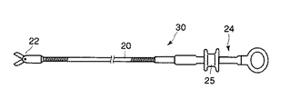
また、図8に示されるように、本実施形態の密巻コイル20を医療用処置具30に適用する場合には、例えば、密巻コイル20の先端に処置部(エンドエフェクタ)22が固着され、密巻コイル20の基端に操作部24が固着される。また、密巻コイル20の内孔に操作ワイヤが挿通され、操作ワイヤの先端にはエンドエフェクタ22の可動エレメントが接続されるとともに、操作ワイヤの基端には操作部24に可動自在に設けられたハンドル25が接続される。したがって、このような構成では、ハンドル25を操作部に対して前後に動かすと、前記操作ワイヤが密巻コイル20に対して前後に動き、エンドエフェクタ22が動作する。また、操作部24の全体を回転させると、密巻コイル20に捩じりトルクが伝わり、密巻コイル20の先端のエンドエフェクタ22が回転する。その際の回転伝達性は、前述した理由により、極めて良好となる。なお、エンドエフェクタ22としては、生検鉗子、把持鉗子、高周波電流を流せる絞扼器、バスケット鉗子等、様々な形態のものを採用することができる。
【0048】
また、本実施形態に係る密巻コイル20を医療用処置具に適用する場合、図11の(a)に示されるようにエンドエフェクタ22を内視鏡のチャンネル2から露出させて、体腔内の組織Xを処置するためにエンドエフェクタ22を組織Xに押し付ける場合を想定すると、チャンネル2から露出した密巻コイル20の先端側部位20Aには、チャンネル2の内部にある手元側部位20Bとは異なり、チャンネル2による径方向での規制が存在しない。このような場合、円形断面の素線8からなる従来の密巻コイル10では、図12の(a)示されるように、エンドエフェクタ22を組織Xに押し付けた際に、組織Xと内視鏡との間で露出する密巻コイル10の先端側部位10Aの途中部分Pが座屈する(圧縮方向への力が働き、横方向に湾曲する)ことがある。これは、従来の円形断面の素線8では、素線8同士が点で接触するため、圧縮方向の力が横方向に逃げ易いためである(図12の(b)参照)。 一方、前述した実施形態の密巻コイル20では、素線18同士が面で接触するため、圧縮方向の力が横方向に逃げにくく(図11の(b)参照)、よって、座屈が発生しにくい(図11の(a)参照)。
【0049】
また、密巻コイル20(本実施形態の密巻コイルに限らず、密巻コイル全般に当てはまることではあるが)を製造する際の注意点として、図13に示されるように、完成した密巻コイル20が「高い真直性」を有していることが重要である。「高い真直性」とは、図13に示すように一端を回転させた時に、密巻コイル20の各部に振れが生じず、真っ直ぐな状態を保ちながら回転するような直線性を有していることを言う。
【0050】
これに対して、密巻コイル20の一部に曲がり癖がある(図14の(a)参照)と、一端を回転させた時に各部に振れが生じる(図14の(b)参照)。特に、密巻コイル20の他端(遠位端:エンドエフェクタ22が設けられる側)に曲がり癖があると、その影響は非常に大きくなる。なぜなら、振れが生じると、内視鏡が湾曲していないにもかかわらず、曲がり癖によりコイル外表面とチャンネル2の内面との間に摩擦抵抗が発生するためである。
【0051】
また、前述した第1の実施形態では、素線18の捩じり剛性が前記第1の基準素線の捩じり剛性と同等になっているが、素線18の曲げ剛性が直径d’の真円を断面形状とする素線(以下、これを第2の基準素線という)のそれと同等(略同一)になるように(すなわち、素線18の第3の軸O4に関する断面2次モーメントI2が前記第2の基準素線のそれと同等になるように)、素線18の断面Sの寸法を設定しても良い。この場合も、密巻コイル20の回転伝達性能(回転追従性)は、前記第2の基準素線によって形成される密巻コイル(以下、第2の基準密巻コイルという)の回転伝達性能より向上する。具体的には、素線18を縦寸法Yおよび横寸法Xの矩形形状に近似して考えると、Y,Xとd’との関係(Y>X,Y=1.5Xとする)を、
d’=(16Y3X/3π)1/4 …(3)
となるように設定する。
【0052】
因みに、式(3)は、以下のように導出される。
【0053】
すなわち、素線18と第2の基準素線の断面2次モーメントIL,IRはそれぞれ、
IL=Y3X/12
IR=πr2/4=πd’4/64
であり、
曲げ剛性が同一であるという条件に基づいて
IL=IR
とすると、
Y3X/12=πd’4/64
となり、この式から
d’=(16Y3X/3π)1/4
となる。
【0054】
また、このように、素線18の曲げ剛性が前記第2の基準素線の曲げ剛性と同等に設定されると、必然的に、素線18の捩じり剛性は、前記第2の基準素線のそれに比べて小さくなる。
【0055】
すなわち、長さLの棒にTの捩じりモーメントを加えた時のねじれ角φは、
(i)円形断面の場合、
φR=32TL/πd’4G …(4)
であり、曲げ剛性が同等であるという条件に基づいて、式(4)に式(3)を代入すると、
φR=(32TL/πG)(3π/16Y3X)
=6TL/1.53X4G
=1.78(TL/X4G)
となり、また、
(ii)矩形断面の場合、
φL=TL/ξ1YX3G
=(1/(0.1958×1.5))(TL/X4G)
=3.40(TL/X4G)
となる。
【0056】
よって、φR/φL=0.52となり、素線18の捩じり剛性は、第2の基準素線の捩じり剛性の約1/2となる。
【0057】
すなわち、素線18の曲げ剛性が第2の基準素線のそれと同等(略同一)になるように、素線18の断面Sの寸法を設定すると、素線18の捩じり剛性が第2の基準素線のそれよりも小さくなる。したがって、密巻コイル20は、その曲げ剛性が前記第2の基準密巻コイルのそれよりも小さく且つその捩じり剛性が前記第2の基準密巻コイルのそれと同等になるため、密巻コイル20の回転伝達性能(回転追従性)は、前記第2の基準密巻コイルのそれよりも向上する。
【0058】
また、素線18の曲げ剛性が所定の円形断面の素線のそれと同等(略同一)になるように、素線18の断面Sの寸法を設定するという観点では、第2の軸O3または第3の軸O4に沿う素線18の断面Sの寸法のうち、最も長い寸法(第1の実施形態では、寸法Y)を直径とする真円を断面形状とする第3の基準素線を想定し、素線18の曲げ剛性を前記第3の基準素線の曲げ剛性と略同一に設定しても良い。この場合も、密巻コイル20の回転伝達性能(回転追従性)は、前記第3の基準素線によって形成される密巻コイル(第3の基準密巻コイル)のそれよりも向上する。すなわち、素線18の曲げ剛性を前記第3の基準素線のそれと同等にして、素線18の断面積を前記第3の基準素線の断面積よりも小さくすれば、素線18の捩じり剛性が前記第3の基準素線の捩じり剛性よりも小さくなり、密巻コイル20の曲げ剛性が第3の基準密巻コイルの対応する曲げ剛性よりも小さくなるとともに、素線18の断面Sの短径寸法(本実施形態では、寸法X)が第3の基準素線の円形断面の直径よりも小さくなることにより、密巻コイル20の単位長さL当たりのコイル巻数(図9の(a)参照)が第3の基準密巻コイルの単位長さL当たりのコイル巻数(図9の(b)参照)よりも多くなるため、過度の湾曲に対する素線18の変形量(素線18の1つの巻回部分にかかる荷重)が小さくなり(つまり、コイルが折れにくくなる)、したがって、所定の湾曲に対する密巻コイル20の曲げからくる抵抗が小さくなる。これにより、全体として、密巻コイル20の回転性能が第3の基準密巻コイルのそれに比べて向上するとともに、先に説明した実施形態と同様の作用効果を得ることもできる。
【0059】
図15〜図17は本発明の第2の実施形態を示している。なお、本実施形態において、第1の実施形態と共通する部分については、以下、同一符号を付してその説明を省略する。
【0060】
図15に示されるように、本実施形態の密巻コイル20Aの素線18Aの断面形状は、第2の軸O3に沿う寸法Yが第3の軸O4に沿う寸法Xよりも大きい長方形を成している。なお、それ以外の特性・形態は第1の実施形態と同一である。
【0061】
このように、本実施形態の密巻コイル20Aは、その素線18Aの断面形状が長方形を成しているため、その製造過程で有利な効果が得られる。すなわち、本実施形態の密巻コイル20Aを製造する場合には、図16に示されるように、第2の軸O3が第1の軸O1と直交するように素線18Aを芯金30に巻き付けていくが、この時、図17の(a)に示されるように素線18Aが芯金30に対して平面で当て付くため、素線18Aが芯金30に対して倒れにくく、安定した生産が可能である。
【0062】
図17(b)には、第1の実施形態の密巻コイル20を製造する過程で素線18が芯金30に対して倒れる状態が示されているが、第1の実施形態の素線18のように円弧部分で芯金30に当て付く断面形状では、製造工程で素線18が芯金30に対して倒れることも考えられる。これに対して、本実施形態のように素線18Aが芯金30に対して平面(平坦部)で当て付く断面形状であると、素線18Aが芯金30に対して倒れにくくなるため、製造時の歩留まりが良好となる。
【0063】
また、本実施形態の密巻コイル20Aの素線断面の平坦部は、第1の実施形態の密巻コイル20の素線断面の円弧部分よりも有利に作用する。例えば、図18に示されるように、密巻コイル20,20A内に操作ワイヤ35を挿通した場合を考えると、第1の実施形態の密巻コイル20では、図18の(b)に示されるように、密巻コイル20の内面の凹凸(円弧部分)により、操作ワイヤ35と密巻コイル20とが点接触するため、密巻コイル20が大きな曲率で湾曲していると、これらの点接触部分に操作ワイヤ35が強く押し付けられてここに集中荷重(図中に矢印で示す)が作用し、操作ワイヤ35の摺動抵抗が高くなる。したがって、操作ワイヤ35の作動、ひいては、操作ワイヤ35によって動作されるエンドエフェクタの作動が重くなる。これに対し、第2の実施形態の密巻コイル20Aでは、図18の(a)に示されるように、密巻コイル20Aの平坦状の内面により、操作ワイヤ35と密巻コイル20Aとが面で接触するため、操作ワイヤ35の摺動抵抗が低く、操作ワイヤ35の作動、ひいては、操作ワイヤ35によって動作されるエンドエフェクタの作動が軽くなる。
【0064】
また、図19に示されるように、密巻コイル20,20Aを内視鏡のチャンネル208内に挿通した場合を考えると、第1の実施形態の密巻コイル20では、図19の(a)に示されるように、密巻コイル20の外面の凹凸(円弧部分)により、内視鏡チャンネル208の内面と密巻コイル20とが点接触するため、内視鏡チャンネル208が大きな曲率で湾曲していると、これらの点接触部分に集中荷重(図中に矢印で示す)が作用し、密巻コイル20の摺動抵抗が高くなる。そのため、密巻コイル20(または、密巻コイル20の先端に設けられた処置部)の前後動作または回転動作が重くなる。これに対し、第2の実施形態の密巻コイル20Aでは、図19の(b)に示されるように、密巻コイル20Aの平坦状の外面により、内視鏡チャンネル208の内面と密巻コイル20Aとが面で接触するため、密巻コイル20Aの摺動抵抗が低く、したがって、密巻コイル20A(または、密巻コイル20Aの先端に設けられた処置部)の前後動作または回転動作が軽くなる。
【0065】
図20〜図22は本発明の第3の実施形態を示している。なお、本実施形態において、第1の実施形態と共通する部分については、以下、同一符号を付してその説明を省略する。
【0066】
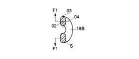
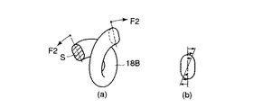
これらの図に示されるように、本実施形態の密巻コイル20Bは、その素線18Bの断面形状が楕円形を成している。なお、それ以外の特性・形態は第1の実施形態と同様である。したがって、第1の実施形態と同様の作用効果を得ることができる。
【0067】
図23〜図25は本発明の第4の実施形態を示している。なお、本実施形態において、第1の実施形態と共通する部分については、以下、同一符号を付してその説明を省略する。
【0068】
これらの図に示されるように、本実施形態の密巻コイル20Cは、円形断面の2本の素線8が径方向に重ねられて成る素線組18Cを、所定の第1の軸O1を中心に所定の長さにわたって螺旋状に密に巻回することによって形成されている。円形断面の2本の素線8を径方向に重ねて成る素線組18C(図24参照)は、第1の実施形態の素線18の断面Sに略類似する縦/横比が1よりも大きい断面S’を形作ることができる。したがって、このような素線組18Cを密巻することによって形成される密巻コイル20Cも、第1の実施形態の密巻コイル20と同様の特性を有することができる。特に、本実施形態では、円形断面の素線8を2本使用するだけで良く、円形断面の素線8を圧延しなくて済むため、縦/横比が大きいコイルを容易に製造することができる。
【0069】
なお、本実施形態においては、図26および図27に示されるように、素線8同士が溶接されていても良い。この場合、図27に示されるように、2本の素線8を平行に配置してその接合部分を溶接し、これによって一体化された素線組18Cを縦方向に連ねて密巻コイルを形成する。このようにすれば、2本の素線8が一体となるため、素線組18Cの曲げ剛性を更に向上させることができる。
【0070】
図28〜図30は本発明の第5の実施形態を示している。なお、本実施形態において、第1の実施形態と共通する部分については、以下、同一符号を付してその説明を省略する。
【0071】
これらの図に示されるように、本実施形態の密巻コイル20Dは、円形断面(断面の縦横寸法比が1:1)の素線28を所定の第1の軸O1を中心に所定の長さにわたって螺旋状に密に巻回することによって形成されている。ただし、素線28は、その素材内部が非均質となっており、両側部の領域(断面が三日月状の領域)R1,R1が剛性の低い特性を有し、かつ、これらの領域R1,R1によって挟まれる中心軸O2付近の領域(断面が略矩形状の領域)R2が剛性の高い特性を有している。
【0072】
したがって、本実施形態の素線28は、同寸法の円形断面の均質材料素線に比べ、 曲げ剛性が同等以上で且つ捩じり剛性が同等以下となり、これにより、本実施形態の密巻コイル20Dは、前記均質材料素線によって形成される密巻コイルに比べ、捩じり剛性が向上し且つ曲げ剛性が低下するため、回転伝達性能が向上する。
【0073】
このように、本実施形態によれば、素線断面形状を円形に維持したままで、回転伝達特性を向上させることができる。また、円形断面の素線と同じ製造設備を使用できる。更に、素線断面の縦横寸法比が1:1であるため、縦長素線に比較して、製造中に倒れが発生しにくく、歩留まりが良くなる。
【0074】
図31〜図33は本発明の第6の実施形態を示している。なお、本実施形態において、第1の実施形態と共通する部分については、以下、同一符号を付してその説明を省略する。
【0075】
これらの図に示されるように、本実施形態の密巻コイル20Eは、円形断面(断面の縦横寸法比が1:1)の素線38を所定の第1の軸O1を中心に所定の長さにわたって螺旋状に密に巻回することによって形成されている。ただし、素線38は、その素材内部が非均質となっており、中心部の領域(断面が円形の領域)R3が剛性の高い特性を有し、かつ、周辺部の領域(断面が環状の領域)R4が剛性の低い特性を有している。
【0076】
したがって、本実施形態の素線38は、同寸法の円形断面の均質材料素線に比べ、 曲げ剛性が同等以上で且つ捩じり剛性が同等以下となり、これにより、本実施形態の密巻コイル20Eは、前記均質材料素線によって形成される密巻コイルに比べ、捩じり剛性が向上し且つ曲げ剛性が低下するため、回転伝達性能が向上する。
【0077】
このように、本実施形態においても、素線断面形状を円形に維持したままで、回転伝達特性を向上させることができるため、第5の実施形態と同様の作用効果を得ることができる。
【0078】
図34〜図36は本発明の第7の実施形態を示している。なお、本実施形態において、第1の実施形態と共通する部分については、以下、同一符号を付してその説明を省略する。
【0079】
これらの図に示されるように、本実施形態の密巻コイル20Fは、円形断面(断面の縦横寸法比が1:1)の素線48を所定の第1の軸O1を中心に所定の長さにわたって螺旋状に密に巻回することによって形成されている。ただし、素線48は、曲げ剛性が異方性を有する特性の素材を使用している。すなわち、この素材は、第1の方向で曲げ剛性が高く、第1の方向と垂直な第2の方向で曲げ剛性が低くなっている。本実施形態では、曲げ剛性が高い第1の方向が、密巻コイル20Fの第1の軸O1に対して直交するように設定されている。
【0080】
したがって、本実施形態の素線48は、同寸法の円形断面の均質材料素線に比べ、 曲げ剛性が同等以上で且つ捩じり剛性が同等以下となり、これにより、本実施形態の密巻コイル20Fは、前記均質材料素線によって形成される密巻コイルに比べ、捩じり剛性が向上し且つ曲げ剛性が低下するため、回転伝達性能が向上する。
【0081】
このように、本実施形態においても、素線断面形状を円形に維持したままで、回転伝達特性を向上させることができるため、第5の実施形態と同様の作用効果を得ることができる。
【0082】
図37〜図40には、以上説明してきたいずれか1つの密巻コイル20〜20Fを力伝達部材として使用した医療用処置具の第1の例が示されている。
【0083】
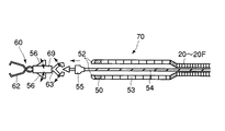
図37および図38に示されるように、この第1の例に係る医療用処置具70は、生体腔に留置可能なクリップ60をエンドエフェクタ(処置部)として有している。密巻コイル20〜20Fの先端側には内径の大きい先端コイル53が接続されている。この先端コイル53は、その内径が密巻コイル20〜20Fのそれよりも大きいため、そのコイル素線の断面の縦/横寸法比が1よりも小さく、したがって、その回転伝達性能が密巻コイル20〜20Fのそれよりも劣っている。
【0084】
なお、図40に示されるように、密巻コイル20〜20Fの基端には、密巻コイル20〜20Fをその第1の軸O1を中心に回転操作するための操作部(回転操作手段)106が設けられている。
【0085】
密巻コイル20〜20Fおよび先端コイル53内を挿通される操作ワイヤ54の先端には、クリップ60と係合可能なフック55が設けられている。また、密巻コイル20〜20Fの先端にはチップ50が固着され、チップ50の先端には上下に切り欠き52が形成されている。
【0086】
クリップ60は、先端に突き出されたフック55に取り付けられる。フック55をクリップ60の後端に押し込むと、クリップ60の後端が変形し、フック55がクリップ60に係合される(図39の(a)参照)
クリップ60にはウイング56が突没自在(突側に付勢されている)に設けられており、ウイング56を畳んだ状態でクリップ60を先端コイル53内に格納できる(図39の(a)参照)。先端コイル53の長さは、概ね、クリップ60を収納できる長さに設定されている。
【0087】
図40に示されるように、医療用処置具70は、クリップ60が先端コイル53内に収納された状態(図39の(a)の状態)で、内視鏡200のチャンネル208内に挿入され、このチャンネル208を介して体内の目標部位(傷口80)へと誘導される。なお、図40において、図42と共通する構成部分については、同一符号が付されている。
【0088】
ウイング56は、クリップ60が先端コイル53の先端から突き出されると、外側に突出して、先端コイル53の切り欠き52に係合し、クリップ60に作用する牽引力を受けることができる(図39の(b)参照)。フック55とクリップ60は相対回転が可能であるが、クリップ60のウイング56がチップ50の切り欠き52に係合しているため、クリップ60は密巻コイル20〜20Fの回転動作に追従して回転する。
【0089】
クリップ60に牽引力がかかると、プロング62が押え管69内に引き込まれ、プロング62の腕同士が接近し、クリップ60を完全に閉じることができる。よって、生体内に生じた傷口80にプロング62を押し当てて、クリップ60を牽引することにより、傷口80を閉じることができる。牽引力がある一定の値に達すると、クリップ60とフック55との間に位置する連結部63が材料破断し、クリップ60が前後に分断するため、傷口80を閉じたままクリップ60を留置することができる(図39の(c)(d)参照)。
【0090】
以上のように、医療用処置具70は、密巻コイル20〜20Fの曲げ剛性が小さいため、内視鏡200の湾曲部204をスムーズに通過できる。したがって、回転伝達性能が劣る先端コイル53を極力短くでき、回転伝達性能の劣化を最小限に抑えることができる。
【0091】
図39には、以上説明してきたいずれか1つの密巻コイル20〜20Fを力伝達部材として使用した医療用処置具の第2の例が示されている。
【0092】
図示のように、この第2の例に係る医療用処置具90では、密巻コイル20〜20Fの先端に、エンドエフェクタとして縛扼器(スネア)92が固着されている。密巻コイル20〜20Fの外側には可撓性を有する外套管94が設けられ、外套管94と密巻コイル20〜20Fは、軸方向に相対的に移動可能であり、また、相対回転も可能である。なお、図中、96は密巻コイル20〜20Fの伸びを防止する伸長規制部材である。
【0093】
スネア92は、外套管94内に収納されると縮径し、収納状態で内視鏡のチャンネル内を通じて体内に挿入される。体内で密巻コイル20〜20Fを押し出し、スネア92を外套管94から突き出すと、スネア92が拡開する。その状態で、密巻コイル20〜20Fの手元側に設けられた操作部106を介して密巻コイル20〜20Fを回転させると、密巻コイル20〜20Fと共にスネア92が外套管94に対して回転し、患部との位置合わせを行なってポリープ等の病変にスネア92を引掛けることができる。その引掛け状態で、密巻コイル20〜20Fを外套管94に対して牽引すると、スネア92によりポリープが縛扼され、その状態で、密巻コイル20〜20Fを介してスネア92に高周波電流を流すと、ポリープが切除される。
【0094】
なお、以上説明してきた技術内容によれば、以下に示されるような各種の構成が得られる。
【0095】
1.素線を所定の第1の軸を中心に所定の長さにわたって螺旋状に密に巻回することによって形成される密巻コイルにおいて、
前記素線は、その素線軸に対して垂直な断面において、前記断面の中心を通り且つ前記第1の軸と垂直な第2の軸に関する断面2次モーメントが、前記断面の中心を通り且つ前記第2の軸に対して垂直な第3の軸に関する断面2次モーメントよりも小さくなるように形成されていることを特徴とする密巻コイル。
【0096】
2.素線を所定の第1の軸を中心に所定の長さにわたって螺旋状に密に巻回することによって形成される密巻コイルにおいて、
前記素線の素線軸に対して垂直な断面は、この断面の中心を通り且つ前記第1の軸と垂直な第2の軸と、前記断面の中心を通り且つ前記第2の軸に対して垂直な第3の軸とを有し、
前記素線の曲げ剛性は、前記第2の軸または前記第3の軸に沿う前記素線の断面寸法のうち最も長い寸法を直径とする真円を断面形状とする基準素線の曲げ剛性よりも大きく、
前記素線の捩じり剛性は、前記基準素線の捩じり剛性と略同一であることを特徴とする密巻コイル。
【0097】
3.素線を所定の第1の軸を中心に所定の長さにわたって螺旋状に密に巻回することによって形成される密巻コイルにおいて、
前記素線の素線軸に対して垂直な断面は、この断面の中心を通り且つ前記第1の軸と垂直な第2の軸と、前記断面の中心を通り且つ前記第2の軸に対して垂直な第3の軸とを有し、
前記素線の曲げ剛性は、前記第2の軸または前記第3の軸に沿う前記素線の断面寸法のうち最も長い寸法を直径とする真円を断面形状とする基準素線の曲げ剛性と略同じであり、
前記素線の捩じり剛性は、前記基準素線の捩じり剛性よりも小さいことを特徴とする密巻コイル。
【0098】
4.素線を所定の第1の軸を中心に所定の長さにわたって螺旋状に密に巻回することによって形成される密巻コイルにおいて、
前記素線の素線軸に対して垂直な断面は、この断面の中心を通り且つ前記第1の軸と垂直な第2の軸と、前記断面の中心を通り且つ前記第2の軸に対して垂直な第3の軸とを有し、
前記第2の軸または前記第3の軸に沿う前記素線の断面寸法のうち最も長い寸法を直径とする真円を断面形状とする基準素線を想定すると、前記素線は、その素線軸に対して垂直な断面における前記第3の軸に関する断面2次モーメントが、前記基準素線における対応する断面2次モーメントよりも大きくなるように形成されていることを特徴とする密巻コイル。
【0099】
5.素線を所定の第1の軸を中心に所定の長さにわたって螺旋状に密に巻回することによって形成される密巻コイルにおいて、
前記素線の素線軸に対して垂直な断面は、この断面の中心を通り且つ前記第1の軸と垂直な第2の軸に沿う寸法が、前記断面の中心を通り且つ前記第2の軸に対して垂直な第3の軸に沿う寸法よりも大きいことを特徴とする密巻コイル。
【0100】
6.第1項ないし第5項のいずれか1項に記載の密巻コイルと、
前記密巻コイルの基端に設けられ、前記密巻コイルをその第1の軸を中心に回転操作するための回転操作手段と、
前記密巻コイルよりも先端側に位置し、前記回転操作手段による回転操作力を前記密巻コイルを介して受ける処置部と、
を具備することを特徴とする医療用処置具。
【0101】
7.前記処置部は、前記密巻コイルの先端に取り付けられていることを特徴とする第6項に記載の医療用処置具。
【0102】
8.前記密巻コイル内には操作ワイヤが進退可能に挿通され、前記操作ワイヤの先端に前記処置部が取り付けられていることを特徴とする第6項に記載の医療用処置具。
【0103】
9.前記処置部は、生体内に留置可能なクリップであることを特徴とする第6項に記載の医療用処置具。
【0104】
10.前記密巻コイルの先端には、前記処置部と前記密巻コイルとの間に位置し且つ前記密巻コイルの内径よりも大きい内径を有する第2の密巻コイルが接続され、
前記クリップは、前記第2の密巻コイルの先端に装着される第1の形態と、前記第2の密巻コイルの内部に格納される第2の形態との間で変形可能であり、
前記第2の密巻コイルの長さは、この第2の密巻コイルの内部に前記第2の形態で格納される前記クリップの軸方向長さと実質的に同じであることを特徴とする第9項に記載の医療用処置具。
【0105】
11.前記第2の密巻コイルは、素線を所定の第4の軸を中心に所定の長さにわたって螺旋状に密に巻回することによって形成され、
前記第2の密巻コイルの前記素線の素線軸に対して垂直な断面は、この断面の中心を通り且つ前記第4の軸と垂直な第5の軸に沿う寸法が、前記断面の中心を通り且つ前記第5の軸に対して垂直な第6の軸に沿う寸法よりも小さいことを特徴とする第10項に記載の医療用処置具。
【0106】
12.内視鏡と組み合わせて使用され、
第1項ないし第5項のいずれか1項に記載の密巻コイルと、
前記密巻コイルが挿通される外套管と、
前記密巻コイルを前記外套管に対して回転させるための手段と、
を具備することを特徴とする医療用処置具。
【0107】
13.内視鏡のチャンネル内に挿通可能であることを特徴とする第1項ないし第5項のいずれか1項に記載の密巻コイル。
【0108】
14.内視鏡のチャンネル内に挿通可能であることを特徴とする第6項ないし第11項のいずれか1項に記載の医療用処置具。
【0109】
15.内視鏡と組み合わせて使用される内視鏡用処置具において、
前記処置具が細い管腔内に挿通される伸長部材を有し、
前記伸長部材が細い管腔に対して相対的に回転できるような手段を有しており、
前記伸長部材が高い捩じり剛性と高い可撓性とを有していることを特徴とする内視鏡用処置具。
【0110】
16.内視鏡と組み合わせて使用される内視鏡用処置具において、
前記処置具が細い管腔内に挿通される密巻コイルを有し、
前記密巻コイルが細い管腔に対して相対的に回転できるような手段を有しており、
前記密巻コイルの素線は、処置具の軸線を基準とした向きについて高い曲げ剛性を有し、かつ、低い捩じり剛性を有していることを特徴とする内視鏡用処置具。
【0111】
【発明の効果】
以上説明したように、本発明によれば、良好な回転伝達性能を有する密巻コイル及びこの密巻コイルを用いた医療用処置具を提供することができる。
【図面の簡単な説明】
【図1】複雑に屈曲する内視鏡のチャンネル内に密巻コイルが挿通された状態を示す模式図である。
【図2】円形断面の素線から成る密巻コイルの半断面図である。
【図3】(a)は図2の密巻コイルをその巻き方向と反対の方向に捩じった際の曲がり梁を形成する素線の部位の曲げ状態を示す概念図、(b)は図2の密巻コイルをその巻き方向に捩じった際の曲がり梁を形成する素線の部位の曲げ状態を示す概念図である。
【図4】(a)は図2の密巻コイルを曲げた際の素線の捩じれ状態を示す概念図、(b)は(a)に示されるように素線に捩じりトルクが作用した時の素線における応力分布図である。
【図5】本発明の第1の実施形態に係る密巻コイルの半断面図である。
【図6】(a)は図5の密巻コイルをその巻き方向と反対の方向に捩じった際の曲がり梁を形成する素線の部位の曲げ状態を示す概念図、(b)は図5の密巻コイルをその巻き方向に捩じった際の曲がり梁を形成する素線の部位の曲げ状態を示す概念図である。
【図7】(a)は図5の密巻コイルを曲げた際の素線の捩じれ状態を示す概念図、(b)は(a)に示されるように素線に捩じりトルクが作用した時の素線における応力分布図である。
【図8】図5の密巻コイルを医療用処置具に適用した一例を示す側面図である。
【図9】(a)は図5の密巻コイルの単位長さ当たりの巻線数を示す断面図、(b)は基準密巻コイルの単位長さ当たりの巻線数を示す断面図である。
【図10】(a)は従来の円形断面の素線から成る密巻コイルの不具合な変形を示す断面図、(b)は従来の矩形断面の素線から成る密巻コイルの不具合な変形を示す断面図、(c)は図5の密巻コイルの変形状態を示す断面図である。
【図11】(a)は本発明の第1の実施形態に係る密巻コイルを備えた医療用処置具を経内視鏡的に体組織に押し付けた状態を示す概略図、(b)は(a)の状況下における密巻コイルの真直状態を示す断面図である。
【図12】(a)は従来の円形断面素線からなる密巻コイルを備えた医療用処置具を経内視鏡的に体組織に押し付けた状態を示す概略図、(b)は(a)の状況下における密巻コイルの座屈状態を示す断面図である。
【図13】高い真直性を有する密巻コイルの側面図である。
【図14】(a)は曲がり癖のある密巻コイルの側面図、(b)は曲がり癖のある密巻コイルを回転させた際に振れが生じる様子を示す概略図、(c)は内視鏡チャンネル挿通下における振れによる悪影響を示すための断面図である。
【図15】本発明の第2の実施形態に係る密巻コイルの半断面図である。
【図16】図15の密巻コイルの製造方法の一部を示す斜視図である。
【図17】(a)は図16の側断面図、(b)は図5の密巻コイルを製造する際の(a)に対応する側断面図である。
【図18】(a)は図15の密巻コイルの使用形態の第1の例を示す断面図、(b)は図5の密巻コイルの使用形態の第1の例を示す断面図である。
【図19】(a)は図15の密巻コイルの使用形態の第2の例を示す断面図、(b)は図5の密巻コイルの使用形態の第2の例を示す断面図である。
【図20】本発明の第3の実施形態に係る密巻コイルの半断面図である。
【図21】図20の密巻コイルをその巻き方向と反対の方向に捩じった際の曲がり梁を形成する素線の部位の曲げ状態を示す概念図である。
【図22】(a)は図20の密巻コイルを曲げた際の素線の捩じれ状態を示す概念図、(b)は(a)に示されるように素線に捩じりトルクが作用した時の素線における応力分布図である。
【図23】本発明の第4の実施形態に係る密巻コイルの半断面図である。
【図24】図23の密巻コイルをその巻き方向と反対の方向に捩じった際の曲がり梁を形成する素線の部位の曲げ状態を示す概念図である。
【図25】図23の密巻コイルを曲げた際の素線の捩じれ状態を示す概念図である。
【図26】図23の密巻コイルの変形例に係る半断面図である。
【図27】素線同士を溶接する状態を示す斜視図である。
【図28】本発明の第5の実施形態に係る密巻コイルの半断面図である。
【図29】(a)は図28の密巻コイルをその巻き方向と反対の方向に捩じった際の曲がり梁を形成する素線の部位の曲げ状態を示す概念図、(b)は図28の密巻コイルをその巻き方向に捩じった際の曲がり梁を形成する素線の部位の曲げ状態を示す概念図である。
【図30】図28の密巻コイルを曲げた際の素線の捩じれ状態を示す概念図である。
【図31】本発明の第6の実施形態に係る密巻コイルの半断面図である。
【図32】(a)は図31の密巻コイルをその巻き方向と反対の方向に捩じった際の曲がり梁を形成する素線の部位の曲げ状態を示す概念図、(b)は図31の密巻コイルをその巻き方向に捩じった際の曲がり梁を形成する素線の部位の曲げ状態を示す概念図である。
【図33】図31の密巻コイルを曲げた際の素線の捩じれ状態を示す概念図である。
【図34】本発明の第7の実施形態に係る密巻コイルの半断面図である。
【図35】(a)は図34の密巻コイルをその巻き方向と反対の方向に捩じった際の曲がり梁を形成する素線の部位の曲げ状態を示す概念図、(b)は図34の密巻コイルをその巻き方向に捩じった際の曲がり梁を形成する素線の部位の曲げ状態を示す概念図である。
【図36】(a)は図34の密巻コイルを曲げた際の素線の捩じれ状態を示す概念図、(b)は(a)に示されるように素線に捩じりトルクが作用した時の素線における応力分布図である。
【図37】第1ないし第7の実施形態に係る密巻コイルを力伝達部材として使用した医療用処置具の第1の例を示す部分側断面図である。
【図38】図37の処置具の先端側の斜視図である。
【図39】図37の処置具の作用を段階的に示す部分側断面図である。
【図40】図37の処置具を内視鏡のチャンネル内に挿通した状態を示す概略図である。
【図41】(a)は第1ないし第7の実施形態に係る密巻コイルを力伝達部材として使用した医療用処置具の第2の例を示す部分側断面図、(b)は(a)の処置具の平面図である。
【図42】従来の処置具を内視鏡のチャンネル内に挿通した状態を示す概略図である。
【図43】円形断面の素線から成る密巻コイルの所定条件下での回転伝達性能を示すグラフ図である。
【符号の説明】
18,18A,18B,18C,28,38,48…素線
20,20A,20B,20C,20D,20E,20F…密巻コイル
O1…第1の軸
O2…素線軸
O3…第2の軸
O4…第3の軸[0001]
BACKGROUND OF THE INVENTION
The present invention relates to a closely wound coil formed by densely winding an element wire spirally over a predetermined length, and a medical treatment instrument using the closely wound coil.
[0002]
[Prior art]
A medical treatment instrument introduced into the body through an endoscope channel generally includes a treatment portion provided at a distal end, an operation portion provided at a proximal side proximal end portion, and an operation force of the operation portion. A force transmission member for transmitting to the portion.
[0003]
Since the force transmission member is inserted into a long channel of an endoscope introduced into a torsional lumen in the body, it can withstand bending, compression, and the like, and the operation force from the operation unit side is ensured. Is required to be transmitted to the treatment unit.
[0004]
For this reason, a closely wound coil formed by densely winding a strand having a circular cross section in a spiral shape over a predetermined length is widely used as the force transmission member (see, for example, Patent Document 1). .
[0005]
FIG. 42 shows a conventional example of a medical treatment instrument including such a closely wound coil as a force transmission member. As shown in the figure, this
[0006]
[Patent Document 1]
JP 56-111221 A
[0007]
[Problems to be solved by the invention]
By the way, in the conventional closely wound coil, there is one big problem. That is, as shown in FIG. 42, when the
[0008]
The rotation transmission performance of the conventional closely wound coil in the bent state as shown in FIG. 42 is schematically shown in FIG. As shown by a solid line in FIG. 43, in the conventional closely wound coil, even if the
[0009]
The present invention has been made by paying attention to the above circumstances, and an object of the present invention is to provide a closely wound coil having good rotation transmission performance and a medical treatment instrument using the closely wound coil. .
[0011]
[Means for Solving the Problems]
In order to solve the above problems, the invention described in claim 1 is:In a closely wound coil formed by winding a strand densely in a spiral shape over a predetermined length around a predetermined first axis, a cross section perpendicular to the strand axis of the strand is A second axis passing through the center of the cross section and perpendicular to the first axis; and a third axis passing through the center of the cross section and perpendicular to the second axis and parallel to the first axis; And the bending rigidity of the strand is a reference strand having a perfect circle as a cross-sectional shape with the longest dimension among the cross-sectional dimensions of the strand along the second axis or the third axis. The torsional rigidity of the strand is less than or equal to the torsional rigidity of the reference strand.
[0013]
Also,Claim 2The densely wound coil formed by densely winding a strand spirally over a predetermined length around a predetermined first axis with respect to the strand axis of the strand The cross section perpendicular to the first axis passes through the center of the cross section and extends along the second axis perpendicular to the first axis. The dimension passes through the center of the cross section and is perpendicular to the second axis. Larger than a dimension along a third axis parallel to the axis of the wire, and the torsional rigidity of the strand is substantially the same as that of a strand having a cross-sectional shape of a perfect circle having a predetermined diameter. When the dimension of the cross section is set, the bending rigidity with respect to the third axis is larger than the bending rigidity of a strand having a perfect circle as a cross section.
[0014]
Also,Claim 3The densely wound coil formed by densely winding a strand spirally over a predetermined length around a predetermined first axis with respect to the strand axis of the strand The cross section perpendicular to the first axis passes through the center of the cross section and extends along the second axis perpendicular to the first axis. The dimension passes through the center of the cross section and is perpendicular to the second axis. Larger than the dimension along the third axis parallel to the axis of the wire, and the bending rigidity of the wire is substantially the same as that of the wire having a perfect circle of a predetermined diameter in cross section. Furthermore, when the dimension of the cross section is set, the torsional rigidity is smaller than the torsional rigidity of the strand having a perfect circle cross section.
Also,Claim 4The invention described inClaims 1 to 3In the invention described in any one of the above, the surface of the strand is provided with two planes parallel to the second axis and perpendicular to the third axis, The strands are in contact with each other on the plane.
Also,Claim 5The invention described in is formed by closely winding a strand set formed by superposing a plurality of strands in a radial direction around a predetermined first axis in a spiral shape over a predetermined length. In the close-wound coil, a cross section perpendicular to the strand axis of the strand set has a dimension passing through the center of the cross section and along a second axis perpendicular to the first axis. And larger than a dimension along a third axis that is perpendicular to the second axis and parallel to the first axis.
[0015]
Also,Claim 6The medical treatment device described inClaims 1 to 3The densely wound coil according to any one of the above, a rotation operation means that is provided at a proximal end of the closely wound coil, and that rotates the densely wound coil around its first axis; And a treatment section that is positioned on the distal end side of the coil and receives the rotational operation force of the rotational operation means via the closely wound coil.
[0016]
DETAILED DESCRIPTION OF THE INVENTION
Before describing specific embodiments of the present invention, the basic concept of the present invention will be described first.
[0017]
In the conventional closely wound coil, there are mainly two causes for causing a delay or the like between the input angle and the output angle (see FIG. 43).
[0018]
The first cause is accumulation of stress due to torsional deformation of the closely wound coil due to the fact that the closely wound coil is not a rigid body. That is, when a rotational force is input to one end of the closely wound coil, if the closely wound coil undergoes torsional deformation, a part of the rotational force is accumulated in the closely wound coil as an internal stress. The rotation angle output at the other end of the coil does not match the rotation angle input at one end of the closely wound coil. Accordingly, when the torsional rigidity of the densely wound coil is large, the accumulation of stress in the closely wound coil is small, so that delay and jumping are unlikely to occur, and therefore the rotation transmission performance is high. On the other hand, when the torsional rigidity of the closely wound coil is small, accumulation of stress in the closely wound coil increases, so that a delay or jump is likely to occur in the rotation, and therefore the rotation transmission performance is deteriorated.
[0019]
The second cause of delay between the input angle and the output angle is a frictional resistance generated between the endoscope channel and the closely wound coil. That is, as shown in FIG. 1, in a state where the densely wound coil 4 is inserted into the
[0020]
Considering the above two causes, in order to improve the rotation transmission performance of the closely wound coil, the accumulation of stress due to torsional deformation of the closely wound coil is reduced, and the endoscope channel and the closely wound coil are It is necessary to reduce the frictional resistance generated during That is, if the torsional rigidity of the closely wound coil is increased and the bending rigidity of the closely wound coil is decreased, the rotation transmission performance of the closely wound coil can be improved.
[0021]
By the way, it can be considered that the torsional rigidity and bending rigidity of the closely wound coil respectively correspond to the bending rigidity and torsional rigidity of the strands forming the closely wound coil. That is, as shown in FIG. 2, when considering a closely wound
[0022]
On the other hand, the bending of the closely wound
[0023]
To summarize the above points, in order to improve the rotation transmission performance of the closely wound
[0024]
However, the conventional closely wound
[0025]
The present inventor has considered all the points described above, and as a result, has found that, under certain conditions, the mutual relationship between the secondary moments of the cross section of the strands is greatly involved in the above conditions. Further, it has been found that, under certain conditions, the above conditions can be easily satisfied even if the strand has a circular cross section.
[0026]
Hereinafter, specific embodiments based on such knowledge (concept of the present invention) will be described.
[0027]
5 to 7 show a first embodiment of the present invention.
[0028]
As shown in FIG. 5, the closely wound
[0029]
Further, in the present embodiment, the
d = (32ξ1YX3/ Π)1/4 ... (1)
It is set to become.
[0030]
Where ξ1Is a constant determined by Y / X.
[0031]
Incidentally, Formula (1) is derived as follows.
[0032]
That is, the twist angle φ when a torsional moment of T is applied to a rod of length L is
(I) When the cross section is circular
φR= 32TL / πd4G (G is the transverse elastic modulus (a constant determined by the material))
And
(Ii) For a rectangular cross section,
φL= TL / ξ1YX3G (Y> X)
And
The fact that the torsional rigidity is equivalent means that the torsion angle (deformation amount) when the same torsional moment is applied is the same.
φR= ΦL
And therefore
32TL / πd4G = TL / ξ1YX3G
And as a result,
d = (32ξ1YX3/ Π)1/4
Get.
[0033]
In the present embodiment, the material of the
[0034]
Thus, in the closely wound
[0035]
In particular, the close-
[0036]
Further, in this way, when the torsional rigidity of the
(I) Sectional moment I of a rectangular section wire (elementary wire 18) having a longitudinal dimension Y and a lateral dimension X (Y = 1.5X)LIs
IL= Y3X / 12
= (1.5X)3X / 12
= 0.2812X4
(Ii) Sectional secondary moment I of a circular section strand (first reference strand) having a diameter dRIs
IR= Πr4/ 4
= (Π / 4) (d / 2)4... (2)
It becomes.
[0037]
Here, substituting equation (1) into equation (2) based on the condition that the torsional rigidity is equivalent,
IR= (Π / 64) (32ξ1YX3/ Π)
It becomes.
[0038]
When Y = 1.5X, ξ1= 0.1958, so
IR= (Π / 64) (32 × 0.1958 × 1.5X4/ Π)
= 0.1468X4
It becomes.
[0039]
Therefore, IL/ IR= 1.91, and the bending rigidity (EI) of the
[0040]
That is, the tightly wound
[0041]
Moreover, the densely wound
[0042]
That is, as shown in FIG. 10A, when the cross-sectional shape of the strands is circular as in the prior art, the
[0043]
On the other hand, the close-
[0044]
Further, conventionally, as shown in FIG. 42, the distal end of the closely wound
[0045]
On the other hand, since the tightly wound
[0046]
In the densely wound
[0047]
As shown in FIG. 8, when the tightly wound
[0048]
In addition, when the tightly wound
[0049]
Further, as shown in FIG. 13, as a precaution for manufacturing the closely wound coil 20 (which is applicable not only to the closely wound coil of the present embodiment but also to the closely wound coil in general), the completed densely wound coil is shown. It is important that the
[0050]
On the other hand, if there is a bending wrinkle in a part of the closely wound coil 20 (see FIG. 14A), vibration occurs in each part when one end is rotated (see FIG. 14B). In particular, if there is a curl at the other end (distal end: the side on which the
[0051]
Further, in the first embodiment described above, the torsional rigidity of the
d '= (16Y3X / 3π)1/4 ... (3)
Set to be.
[0052]
Incidentally, Formula (3) is derived as follows.
[0053]
That is, the cross-sectional secondary moment I of the
IL= Y3X / 12
IR= Πr2/ 4 = πd ′4/ 64
And
Based on the condition that the bending stiffness is the same
IL= IR
Then,
Y3X / 12 = πd ′4/ 64
And from this equation
d '= (16Y3X / 3π)1/4
It becomes.
[0054]
In addition, when the bending stiffness of the
[0055]
That is, the twist angle φ when a torsional moment of T is applied to a rod of length L is
(I) In the case of a circular cross section,
φR= 32TL / πd '4G (4)
And substituting equation (3) into equation (4) based on the condition that the bending stiffness is equivalent,
φR= (32TL / πG) (3π / 16Y3X)
= 6TL / 1.53X4G
= 1.78 (TL / X4G)
And again
(Ii) In the case of a rectangular cross section,
φL= TL / ξ1YX3G
= (1 / (0.1958 × 1.5)) (TL / X4G)
= 3.40 (TL / X4G)
It becomes.
[0056]
Therefore, φR/ ΦL= 0.52 and the torsional rigidity of the
[0057]
That is, when the dimension of the cross section S of the
[0058]
From the viewpoint of setting the dimension of the cross section S of the
[0059]
15 to 17 show a second embodiment of the present invention. In the present embodiment, portions common to the first embodiment are denoted by the same reference numerals and description thereof is omitted.
[0060]
As shown in FIG. 15, the cross-sectional shape of the
[0061]
Thus, since the cross-sectional shape of the
[0062]
FIG. 17B shows a state in which the
[0063]
Further, the flat portion of the cross section of the strand of the densely wound
[0064]
Further, as shown in FIG. 19, when considering the case where the closely wound coils 20 and 20A are inserted into the
[0065]
20 to 22 show a third embodiment of the present invention. In the present embodiment, portions common to the first embodiment are denoted by the same reference numerals and description thereof is omitted.
[0066]
As shown in these drawings, in the closely wound coil 20B of the present embodiment, the cross-sectional shape of the
[0067]
23 to 25 show a fourth embodiment of the present invention. In the present embodiment, portions common to the first embodiment are denoted by the same reference numerals and description thereof is omitted.
[0068]
As shown in these drawings, the close-
[0069]
In the present embodiment, as shown in FIGS. 26 and 27, the
[0070]
28 to 30 show a fifth embodiment of the present invention. In the present embodiment, portions common to the first embodiment are denoted by the same reference numerals and description thereof is omitted.
[0071]
As shown in these drawings, the closely wound
[0072]
Accordingly, the
[0073]
As described above, according to the present embodiment, it is possible to improve the rotation transmission characteristic while keeping the wire cross-sectional shape circular. Moreover, the same manufacturing equipment as that of the strand having a circular cross section can be used. Furthermore, since the vertical / horizontal dimension ratio of the wire cross section is 1: 1, compared to the vertically long wire, the collapse is less likely to occur during manufacturing, and the yield is improved.
[0074]
31 to 33 show a sixth embodiment of the present invention. In the present embodiment, portions common to the first embodiment are denoted by the same reference numerals and description thereof is omitted.
[0075]
As shown in these drawings, the closely wound coil 20E according to the present embodiment has a
[0076]
Accordingly, the
[0077]
As described above, also in the present embodiment, the rotation transmission characteristics can be improved while maintaining the cross-sectional shape of the strands in a circular shape. Therefore, the same operational effects as those of the fifth embodiment can be obtained.
[0078]
34 to 36 show a seventh embodiment of the present invention. In the present embodiment, portions common to the first embodiment are denoted by the same reference numerals and description thereof is omitted.
[0079]
As shown in these drawings, the closely wound
[0080]
Accordingly, the
[0081]
As described above, also in the present embodiment, the rotation transmission characteristics can be improved while maintaining the cross-sectional shape of the strands in a circular shape. Therefore, the same operational effects as those of the fifth embodiment can be obtained.
[0082]
37 to 40 show a first example of a medical treatment instrument using any one of the above-described tightly wound coils 20 to 20F as a force transmission member.
[0083]
As shown in FIGS. 37 and 38, the
[0084]
As shown in FIG. 40, at the base end of the closely wound coils 20 to 20F, an operation unit (rotating operation means) for rotating the densely wound
[0085]
A
[0086]
The
The
[0087]
As shown in FIG. 40, the
[0088]
When the
[0089]
When the traction force is applied to the
[0090]
As described above, the
[0091]
FIG. 39 shows a second example of a medical treatment instrument using any one of the closely wound coils 20 to 20F described above as a force transmission member.
[0092]
As shown in the drawing, in the
[0093]
The
[0094]
In addition, according to the technical content demonstrated above, the various structures as shown below are obtained.
[0095]
1. In a close-wound coil formed by winding a strand densely in a spiral shape over a predetermined length around a predetermined first axis,
In the cross section perpendicular to the element wire axis, the element wire passes through the center of the cross section, and the second moment of section with respect to the second axis perpendicular to the first axis passes through the center of the cross section and A densely wound coil, characterized in that the coil is formed so as to be smaller than a second moment of section with respect to a third axis perpendicular to the second axis.
[0096]
2. In a close-wound coil formed by winding a strand densely in a spiral shape over a predetermined length around a predetermined first axis,
A cross section perpendicular to the element wire axis of the element wire passes through the center of the cross section and is perpendicular to the first axis, and passes through the center of the cross section and is relative to the second axis. A third axis that is vertical,
The bending rigidity of the strand is greater than the bending stiffness of a reference strand having a cross-sectional shape of a perfect circle whose diameter is the longest dimension among the cross-sectional dimensions of the strand along the second axis or the third axis. Big
The closely wound coil according to claim 1, wherein the torsional rigidity of the strand is substantially the same as the torsional rigidity of the reference strand.
[0097]
3. In a close-wound coil formed by winding a strand densely in a spiral shape over a predetermined length around a predetermined first axis,
A cross section perpendicular to the element wire axis of the element wire passes through the center of the cross section and is perpendicular to the first axis, and passes through the center of the cross section and is relative to the second axis. A third axis that is vertical,
The bending stiffness of the strand is the bending stiffness of a reference strand having a cross-sectional shape of a perfect circle whose diameter is the longest dimension among the cross-sectional dimensions of the strand along the second axis or the third axis. Almost the same,
The closely wound coil according to claim 1, wherein a torsional rigidity of the strand is smaller than a torsional rigidity of the reference strand.
[0098]
4). In a close-wound coil formed by winding a strand densely in a spiral shape over a predetermined length around a predetermined first axis,
A cross section perpendicular to the element wire axis of the element wire passes through the center of the cross section and is perpendicular to the first axis, and passes through the center of the cross section and is relative to the second axis. A third axis that is vertical,
Assuming a reference strand whose cross-sectional shape is a perfect circle whose diameter is the longest dimension among the cross-sectional dimensions of the strand along the second axis or the third axis, the strand is the strand axis. A densely wound coil, wherein a cross-sectional secondary moment with respect to the third axis in a cross-section perpendicular to the cross-sectional moment is greater than a corresponding cross-sectional secondary moment in the reference strand.
[0099]
5. In a close-wound coil formed by winding a strand densely in a spiral shape over a predetermined length around a predetermined first axis,
The cross section perpendicular to the strand axis of the strand passes through the center of the cross section, and the dimension along the second axis perpendicular to the first axis passes through the center of the cross section and the second axis. A closely wound coil characterized by being larger than a dimension along a third axis perpendicular to the coil.
[0100]
6). The closely wound coil according to any one of Items 1 to 5,
A rotation operating means provided at a proximal end of the densely wound coil, for rotating the densely wound coil around its first axis;
A treatment section that is located on the tip side of the densely wound coil and receives the rotational operation force by the rotational operation means via the densely wound coil;
A medical treatment instrument comprising:
[0101]
7). The medical treatment instrument according to claim 6, wherein the treatment section is attached to a tip of the closely wound coil.
[0102]
8). The medical treatment instrument according to claim 6, wherein an operation wire is inserted into the tightly wound coil so as to be able to advance and retreat, and the treatment portion is attached to a distal end of the operation wire.
[0103]
9. The medical treatment instrument according to claim 6, wherein the treatment section is a clip that can be placed in a living body.
[0104]
10. Connected to the tip of the closely wound coil is a second closely wound coil located between the treatment portion and the closely wound coil and having an inner diameter larger than the inner diameter of the closely wound coil,
The clip is deformable between a first form attached to the tip of the second densely wound coil and a second form housed inside the second closely wound coil;
The length of the second closely wound coil is substantially the same as the axial length of the clip stored in the second form inside the second closely wound coil. 10. A medical treatment instrument according to item 9.
[0105]
11. The second densely wound coil is formed by densely winding an element wire spirally over a predetermined length around a predetermined fourth axis,
The cross section of the second densely wound coil perpendicular to the strand axis of the strand has a dimension passing through the center of the cross section and along the fifth axis perpendicular to the fourth axis. The medical treatment instrument according to
[0106]
12 Used in combination with an endoscope,
The closely wound coil according to any one of Items 1 to 5,
An outer tube through which the tightly wound coil is inserted;
Means for rotating the closely wound coil relative to the mantle tube;
A medical treatment instrument comprising:
[0107]
13. 6. The close-wound coil according to any one of claims 1 to 5, wherein the coil can be inserted into a channel of an endoscope.
[0108]
14 The medical treatment instrument according to any one of items 6 to 11, which can be inserted into a channel of an endoscope.
[0109]
15. In an endoscope treatment tool used in combination with an endoscope,
The treatment instrument has an elongated member inserted into a narrow lumen;
Means for allowing the elongate member to rotate relative to the narrow lumen;
An endoscope treatment tool, wherein the extension member has high torsional rigidity and high flexibility.
[0110]
16. In an endoscope treatment tool used in combination with an endoscope,
The treatment instrument has a tightly wound coil that is inserted into a thin lumen;
Means for allowing the closely wound coil to rotate relative to a thin lumen;
The treatment instrument for an endoscope, wherein the wire of the closely wound coil has a high bending rigidity with respect to an orientation with respect to the axis of the treatment tool, and a low torsional rigidity.
[0111]
【The invention's effect】
As described above, according to the present invention, it is possible to provide a tightly wound coil having good rotation transmission performance and a medical treatment instrument using this closely wound coil.
[Brief description of the drawings]
FIG. 1 is a schematic diagram showing a state where a closely wound coil is inserted into a channel of an endoscope that is bent in a complicated manner.
FIG. 2 is a half cross-sectional view of a closely wound coil made of a strand having a circular cross section.
3A is a conceptual diagram showing a bending state of a portion of a strand forming a bending beam when the densely wound coil of FIG. 2 is twisted in a direction opposite to the winding direction; FIG. It is a conceptual diagram which shows the bending state of the site | part of the strand which forms the bending beam at the time of twisting the closely wound coil of FIG. 2 in the winding direction.
4A is a conceptual diagram showing a twisted state of a strand when the closely wound coil of FIG. 2 is bent, and FIG. 4B is a diagram showing a twisting torque acting on the strand as shown in FIG. It is the stress distribution figure in the strand at the time of doing.
FIG. 5 is a half sectional view of the closely wound coil according to the first embodiment of the present invention.
6A is a conceptual diagram showing a bending state of a portion of a strand forming a bent beam when the densely wound coil of FIG. 5 is twisted in a direction opposite to the winding direction; FIG. It is a conceptual diagram which shows the bending state of the site | part of the strand which forms the bending beam at the time of twisting the closely wound coil of FIG. 5 in the winding direction.
7A is a conceptual diagram showing a twisted state of a strand when the closely wound coil of FIG. 5 is bent, and FIG. 7B is a diagram showing a twisting torque acting on the strand as shown in FIG. It is the stress distribution figure in the strand when it did.
FIG. 8 is a side view showing an example in which the closely wound coil of FIG. 5 is applied to a medical treatment instrument.
9A is a cross-sectional view showing the number of windings per unit length of the close-wound coil in FIG. 5, and FIG. 9B is a cross-sectional view showing the number of turns per unit length of the reference close-wound coil. is there.
10A is a cross-sectional view showing a defective deformation of a densely wound coil made of a conventional wire having a circular cross section, and FIG. 10B is a cross sectional view showing a troubled deformation of a densely wound coil made of a wire having a conventional rectangular cross section. Sectional drawing shown, (c) is a sectional view showing a deformed state of the closely wound coil of FIG.
FIG. 11A is a schematic view showing a state where a medical treatment instrument including a close-wound coil according to the first embodiment of the present invention is pressed endoscopically to body tissue, and FIG. It is sectional drawing which shows the straight state of the closely wound coil in the condition of (a).
12A is a schematic view showing a state in which a medical treatment instrument having a close-wound coil made of a conventional circular cross-section element wire is pressed endoscopically on a body tissue, and FIG. It is sectional drawing which shows the buckled state of the closely wound coil in the condition of ().
FIG. 13 is a side view of a closely wound coil having high straightness.
14 (a) is a side view of a closely wound coil having a curved surface, FIG. 14 (b) is a schematic view showing a state in which vibration is generated when the closely wound coil having a curved surface is rotated, and FIG. It is sectional drawing for showing the bad influence by shake under insertion of an endoscope channel.
FIG. 15 is a half sectional view of a closely wound coil according to a second embodiment of the present invention.
16 is a perspective view showing a part of the manufacturing method of the closely wound coil of FIG. 15; FIG.
17 (a) is a side sectional view of FIG. 16, and FIG. 17 (b) is a side sectional view corresponding to FIG. 5 (a) when manufacturing the closely wound coil of FIG.
18A is a cross-sectional view showing a first example of the usage pattern of the closely wound coil of FIG. 15, and FIG. 18B is a cross-sectional view showing a first example of the usage pattern of the closely wound coil of FIG. is there.
19A is a cross-sectional view showing a second example of the usage pattern of the closely wound coil of FIG. 15, and FIG. 19B is a cross-sectional view showing a second example of the usage pattern of the closely wound coil of FIG. is there.
FIG. 20 is a half sectional view of a closely wound coil according to a third embodiment of the present invention.
21 is a conceptual diagram showing a bending state of a portion of a strand forming a bending beam when the closely wound coil of FIG. 20 is twisted in a direction opposite to its winding direction.
22A is a conceptual diagram showing a twisted state of a strand when the closely wound coil of FIG. 20 is bent, and FIG. 22B is a diagram showing a twisting torque acting on the strand as shown in FIG. It is the stress distribution figure in the strand when it did.
FIG. 23 is a half sectional view of a closely wound coil according to a fourth embodiment of the present invention.
24 is a conceptual diagram showing a bending state of a portion of a strand forming a bending beam when the closely wound coil of FIG. 23 is twisted in a direction opposite to its winding direction.
25 is a conceptual diagram showing a twisted state of a strand when the closely wound coil of FIG. 23 is bent.
26 is a half cross-sectional view according to a variation of the closely wound coil of FIG.
FIG. 27 is a perspective view showing a state in which the strands are welded together.
FIG. 28 is a half sectional view of a closely wound coil according to a fifth embodiment of the present invention.
29A is a conceptual diagram showing a bending state of a portion of a strand forming a bending beam when the closely wound coil of FIG. 28 is twisted in a direction opposite to its winding direction, and FIG. It is a conceptual diagram which shows the bending state of the site | part of the strand which forms the bending beam at the time of twisting the closely wound coil of FIG. 28 in the winding direction.
30 is a conceptual diagram showing a twisted state of a strand when the closely wound coil of FIG. 28 is bent.
FIG. 31 is a half sectional view of a closely wound coil according to a sixth embodiment of the present invention.
32A is a conceptual diagram showing a bending state of a portion of a strand forming a bending beam when the densely wound coil of FIG. 31 is twisted in a direction opposite to its winding direction; FIG. It is a conceptual diagram which shows the bending state of the site | part of the strand which forms the bending beam at the time of twisting the closely wound coil of FIG. 31 in the winding direction.
33 is a conceptual diagram showing a twisted state of a strand when the closely wound coil of FIG. 31 is bent.
FIG. 34 is a half sectional view of a closely wound coil according to a seventh embodiment of the present invention.
35A is a conceptual diagram showing a bending state of a portion of a strand forming a bending beam when the densely wound coil of FIG. 34 is twisted in a direction opposite to its winding direction; FIG. It is a conceptual diagram which shows the bending state of the site | part of the strand which forms the bending beam at the time of twisting the closely wound coil of FIG. 34 in the winding direction.
36 (a) is a conceptual diagram showing the twisted state of the strand when the closely wound coil of FIG. 34 is bent, and FIG. 36 (b) is a diagram showing twisting torque acting on the strand as shown in (a). It is the stress distribution figure in the strand when it did.
FIG. 37 is a partial sectional side view showing a first example of a medical treatment instrument using a closely wound coil according to the first to seventh embodiments as a force transmission member.
38 is a perspective view of the distal end side of the treatment instrument in FIG. 37. FIG.
39 is a partial side cross-sectional view showing the operation of the treatment instrument of FIG. 37 in stages.
40 is a schematic view showing a state in which the treatment instrument of FIG. 37 is inserted into a channel of an endoscope.
41 (a) is a partial side cross-sectional view showing a second example of a medical treatment instrument using the closely wound coil according to the first to seventh embodiments as a force transmission member, and FIG. 41 (b) is a diagram (a). It is a top view of the treatment tool.
FIG. 42 is a schematic view showing a state where a conventional treatment instrument is inserted into a channel of an endoscope.
FIG. 43 is a graph showing the rotation transmission performance of a closely wound coil made of a strand having a circular cross section under a predetermined condition.
[Explanation of symbols]
18, 18A, 18B, 18C, 28, 38, 48 ... Wire
20, 20A, 20B, 20C, 20D, 20E, 20F ... closely wound coils
O1 ... first axis
O2 ... Strand axis
O3 ... second axis
O4 ... third axis
Claims (6)
前記素線の素線軸に対して垂直な断面は、この断面の中心を通り且つ前記第1の軸と垂直な第2の軸と、前記断面の中心を通り且つ前記第2の軸に対して垂直で前記第1の軸と平行な第3の軸とを有し、
前記素線の曲げ剛性は、前記第2の軸または前記第3の軸に沿う前記素線の断面寸法のうち最も長い寸法を直径とする真円を断面形状とする基準素線の曲げ剛性と略同じであり、
前記素線の捩じり剛性は、前記基準素線の捩じり剛性以下であることを特徴とする密巻コイル。In a close-wound coil formed by winding a strand densely in a spiral shape over a predetermined length around a predetermined first axis,
The cross section perpendicular to the element wire axis of the element wire passes through the center of the cross section and is perpendicular to the first axis, and passes through the center of the cross section and is relative to the second axis. A third axis perpendicular and parallel to the first axis;
The bending rigidity of the strand is the bending stiffness of a reference strand having a perfect circle having a longest diameter as a cross-sectional shape among the cross-sectional dimensions of the strand along the second axis or the third axis. Almost the same,
The closely wound coil according to claim 1, wherein the torsional rigidity of the strand is equal to or less than the torsional rigidity of the reference strand.
前記素線の素線軸に対して垂直な断面は、この断面の中心を通り且つ前記第1の軸と垂直な第2の軸に沿う寸法が、前記断面の中心を通り且つ前記第2の軸に対して垂直で前記第1の軸に平行な第3の軸に沿う寸法よりも大きく、
前記素線は、その捩じり剛性が、所定の直径の真円を断面形状とする素線のそれと略同一になるように、前記断面の寸法を設定した時に、第3の軸に関する曲げ剛性が真円を断面形状とする素線の曲げ剛性よりも大きいことを特徴とする密巻コイル。In a close-wound coil formed by winding a strand densely in a spiral shape over a predetermined length around a predetermined first axis,
The cross section perpendicular to the strand axis of the strand passes through the center of the cross section and along the second axis perpendicular to the first axis, and the dimension passes through the center of the cross section and the second axis. Greater than a dimension along a third axis perpendicular to and parallel to the first axis,
When the dimension of the cross section is set so that the torsional rigidity of the strand is substantially the same as that of a strand having a cross-sectional shape of a perfect circle having a predetermined diameter, the bending stiffness with respect to the third axis is set. A densely wound coil characterized in that is larger than the bending stiffness of a strand having a perfect circle cross-sectional shape.
前記素線の素線軸に対して垂直な断面は、この断面の中心を通り且つ前記第1の軸と垂直な第2の軸に沿う寸法が、前記断面の中心を通り且つ前記第2の軸に対して垂直で前記第1の軸に平行な第3の軸に沿う寸法よりも大きく、
前記素線は、第3の軸に関する曲げ剛性が、所定の直径の真円を断面形状とする素線のそれと略同一になるように、前記断面の寸法を設定した時に、捩じり剛性が真円を断面形状とする素線の捩じり剛性よりも小さいことを特徴とする密巻コイル。In a close-wound coil formed by winding a strand densely in a spiral shape over a predetermined length around a predetermined first axis,
The cross section perpendicular to the strand axis of the strand passes through the center of the cross section and along the second axis perpendicular to the first axis, and the dimension passes through the center of the cross section and the second axis. Greater than a dimension along a third axis perpendicular to and parallel to the first axis,
The strand has a torsional stiffness when the dimension of the cross section is set so that the bending stiffness with respect to the third axis is substantially the same as that of the strand having a cross-sectional shape of a perfect circle having a predetermined diameter. A densely wound coil characterized by being smaller than the torsional rigidity of a strand having a perfect circle cross section.
前記平面で前記素線同士が接触していることを特徴とする請求項1ないし請求項3のいずれか1項に記載の密巻コイル。The surface of the strand is provided with two planes parallel to the second axis and perpendicular to the third axis,
The densely wound coil according to any one of claims 1 to 3 , wherein the strands are in contact with each other on the plane.
前記素線組の素線軸に対して垂直な断面は、この断面の中心を通り且つ前記第1の軸と垂直な第2の軸に沿う寸法が、前記断面の中心を通り且つ前記第2の軸に対して垂直で前記第1の軸に平行な第3の軸に沿う寸法よりも大きいことを特徴とする密巻コイル。In the closely wound coil formed by winding a strand set formed by overlapping a plurality of strands in a radial direction in a spiral manner over a predetermined length around a predetermined first axis,
The cross section perpendicular to the strand axis of the strand set passes through the center of the cross section and along the second axis perpendicular to the first axis, and the dimension passes through the center of the cross section and the second axis. A densely wound coil characterized by being larger than a dimension along a third axis perpendicular to the axis and parallel to the first axis.
前記密巻コイルの基端に設けられ、前記密巻コイルをその第1の軸を中心に回転操作するための回転操作手段と、
前記密巻コイルよりも先端側に位置し、前記回転操作手段による回転操作力を前記密巻コイルを介して受ける処置部と、
を具備することを特徴とする医療用処置具。The closely wound coil according to any one of claims 1 to 3 ,
A rotation operating means provided at a proximal end of the densely wound coil, for rotating the densely wound coil around its first axis;
A treatment section that is located on the tip side of the densely wound coil and receives the rotational operation force by the rotational operation means via the densely wound coil;
A medical treatment instrument comprising:
Priority Applications (4)
| Application Number | Priority Date | Filing Date | Title |
|---|---|---|---|
| JP2003056215A JP4414662B2 (en) | 2003-03-03 | 2003-03-03 | Closely wound coil and medical treatment tool using the closely wound coil |
| US10/790,261 US20040243108A1 (en) | 2003-03-03 | 2004-03-01 | Close-wound coil and medical treatment tool using this coil |
| EP04004705.2A EP1454588B1 (en) | 2003-03-03 | 2004-03-01 | Force transmission coil for flexible endoscopic instrument and medical treatment tool using said coil |
| US12/420,596 US8672952B2 (en) | 2003-03-03 | 2009-04-08 | Close-wound coil and medical treatment tool using this coil |
Applications Claiming Priority (1)
| Application Number | Priority Date | Filing Date | Title |
|---|---|---|---|
| JP2003056215A JP4414662B2 (en) | 2003-03-03 | 2003-03-03 | Closely wound coil and medical treatment tool using the closely wound coil |
Related Child Applications (1)
| Application Number | Title | Priority Date | Filing Date |
|---|---|---|---|
| JP2009230798A Division JP4960424B2 (en) | 2009-10-02 | 2009-10-02 | Closely wound coil and medical treatment tool using the closely wound coil |
Publications (2)
| Publication Number | Publication Date |
|---|---|
| JP2004261463A JP2004261463A (en) | 2004-09-24 |
| JP4414662B2 true JP4414662B2 (en) | 2010-02-10 |
Family
ID=32821161
Family Applications (1)
| Application Number | Title | Priority Date | Filing Date |
|---|---|---|---|
| JP2003056215A Expired - Fee Related JP4414662B2 (en) | 2003-03-03 | 2003-03-03 | Closely wound coil and medical treatment tool using the closely wound coil |
Country Status (3)
| Country | Link |
|---|---|
| US (2) | US20040243108A1 (en) |
| EP (1) | EP1454588B1 (en) |
| JP (1) | JP4414662B2 (en) |
Families Citing this family (63)
| Publication number | Priority date | Publication date | Assignee | Title |
|---|---|---|---|---|
| JP2006528053A (en) * | 2003-05-16 | 2006-12-14 | ウィルソン−クック・メディカル・インコーポレーテッド | Medical instrument handle |
| US7641621B2 (en) * | 2003-08-25 | 2010-01-05 | Boston Scientific Scimed, Inc. | Elongated intra-lumenal medical device |
| JP4497454B2 (en) * | 2004-04-06 | 2010-07-07 | 朝日インテック株式会社 | Medical tools |
| JP2006158668A (en) * | 2004-12-07 | 2006-06-22 | Olympus Corp | Treatment instrument for endoscope |
| JP4880251B2 (en) | 2005-06-21 | 2012-02-22 | オリンパスメディカルシステムズ株式会社 | High frequency treatment tool |
| US7785250B2 (en) * | 2005-08-11 | 2010-08-31 | Granit Medical Innovation, Llc | Endoscopic instrument assembly with separable operative tip and associated medical method |
| EP1878402A1 (en) * | 2006-07-13 | 2008-01-16 | Bien-Air Holding SA | Device for coupling between a leading shaft and a led shaft of a surgical or dental handpiece |
| US8062306B2 (en) | 2006-12-14 | 2011-11-22 | Ethicon Endo-Surgery, Inc. | Manually articulating devices |
| JP4526544B2 (en) * | 2007-02-08 | 2010-08-18 | オリンパスメディカルシステムズ株式会社 | Endoscopic treatment tool |
| JP5042700B2 (en) * | 2007-02-08 | 2012-10-03 | オリンパスメディカルシステムズ株式会社 | Endoscopic treatment tool |
| EP1955657B1 (en) * | 2007-02-08 | 2011-01-12 | Olympus Medical Systems Corp. | Treatment tool for endoscope |
| US7655004B2 (en) | 2007-02-15 | 2010-02-02 | Ethicon Endo-Surgery, Inc. | Electroporation ablation apparatus, system, and method |
| JP4956287B2 (en) | 2007-06-06 | 2012-06-20 | オリンパスメディカルシステムズ株式会社 | Capsule endoscope system and program |
| US8579897B2 (en) | 2007-11-21 | 2013-11-12 | Ethicon Endo-Surgery, Inc. | Bipolar forceps |
| US20090112059A1 (en) | 2007-10-31 | 2009-04-30 | Nobis Rudolph H | Apparatus and methods for closing a gastrotomy |
| US8771260B2 (en) | 2008-05-30 | 2014-07-08 | Ethicon Endo-Surgery, Inc. | Actuating and articulating surgical device |
| US8906035B2 (en) | 2008-06-04 | 2014-12-09 | Ethicon Endo-Surgery, Inc. | Endoscopic drop off bag |
| US8403926B2 (en) | 2008-06-05 | 2013-03-26 | Ethicon Endo-Surgery, Inc. | Manually articulating devices |
| US8347754B1 (en) * | 2008-07-02 | 2013-01-08 | Titan Medical Inc. | Multi articulating robatic instrument |
| US8888792B2 (en) | 2008-07-14 | 2014-11-18 | Ethicon Endo-Surgery, Inc. | Tissue apposition clip application devices and methods |
| JP5280767B2 (en) * | 2008-08-14 | 2013-09-04 | 富士フイルム株式会社 | Repetitive clip treatment tool |
| US8157834B2 (en) | 2008-11-25 | 2012-04-17 | Ethicon Endo-Surgery, Inc. | Rotational coupling device for surgical instrument with flexible actuators |
| US8361066B2 (en) | 2009-01-12 | 2013-01-29 | Ethicon Endo-Surgery, Inc. | Electrical ablation devices |
| US9737334B2 (en) | 2009-03-06 | 2017-08-22 | Ethicon Llc | Methods and devices for accessing a body cavity |
| US9474540B2 (en) | 2009-10-08 | 2016-10-25 | Ethicon-Endo-Surgery, Inc. | Laparoscopic device with compound angulation |
| US20110098704A1 (en) | 2009-10-28 | 2011-04-28 | Ethicon Endo-Surgery, Inc. | Electrical ablation devices |
| US8608652B2 (en) | 2009-11-05 | 2013-12-17 | Ethicon Endo-Surgery, Inc. | Vaginal entry surgical devices, kit, system, and method |
| US8496574B2 (en) | 2009-12-17 | 2013-07-30 | Ethicon Endo-Surgery, Inc. | Selectively positionable camera for surgical guide tube assembly |
| US8506564B2 (en) | 2009-12-18 | 2013-08-13 | Ethicon Endo-Surgery, Inc. | Surgical instrument comprising an electrode |
| US9028483B2 (en) | 2009-12-18 | 2015-05-12 | Ethicon Endo-Surgery, Inc. | Surgical instrument comprising an electrode |
| US9005198B2 (en) | 2010-01-29 | 2015-04-14 | Ethicon Endo-Surgery, Inc. | Surgical instrument comprising an electrode |
| US8562592B2 (en) | 2010-05-07 | 2013-10-22 | Ethicon Endo-Surgery, Inc. | Compound angle laparoscopic methods and devices |
| US9226760B2 (en) | 2010-05-07 | 2016-01-05 | Ethicon Endo-Surgery, Inc. | Laparoscopic devices with flexible actuation mechanisms |
| US8460337B2 (en) | 2010-06-09 | 2013-06-11 | Ethicon Endo-Surgery, Inc. | Selectable handle biasing |
| US10092291B2 (en) | 2011-01-25 | 2018-10-09 | Ethicon Endo-Surgery, Inc. | Surgical instrument with selectively rigidizable features |
| US9314620B2 (en) | 2011-02-28 | 2016-04-19 | Ethicon Endo-Surgery, Inc. | Electrical ablation devices and methods |
| US9233241B2 (en) | 2011-02-28 | 2016-01-12 | Ethicon Endo-Surgery, Inc. | Electrical ablation devices and methods |
| US9254169B2 (en) | 2011-02-28 | 2016-02-09 | Ethicon Endo-Surgery, Inc. | Electrical ablation devices and methods |
| WO2012125785A1 (en) | 2011-03-17 | 2012-09-20 | Ethicon Endo-Surgery, Inc. | Hand held surgical device for manipulating an internal magnet assembly within a patient |
| EP2612608B1 (en) * | 2011-09-12 | 2014-12-17 | Olympus Medical Systems Corp. | Medical coil, method of manufacturing same, and medical apparatus |
| US9427255B2 (en) | 2012-05-14 | 2016-08-30 | Ethicon Endo-Surgery, Inc. | Apparatus for introducing a steerable camera assembly into a patient |
| US9078662B2 (en) | 2012-07-03 | 2015-07-14 | Ethicon Endo-Surgery, Inc. | Endoscopic cap electrode and method for using the same |
| US9545290B2 (en) | 2012-07-30 | 2017-01-17 | Ethicon Endo-Surgery, Inc. | Needle probe guide |
| US9572623B2 (en) | 2012-08-02 | 2017-02-21 | Ethicon Endo-Surgery, Inc. | Reusable electrode and disposable sheath |
| US10314649B2 (en) | 2012-08-02 | 2019-06-11 | Ethicon Endo-Surgery, Inc. | Flexible expandable electrode and method of intraluminal delivery of pulsed power |
| US9277957B2 (en) | 2012-08-15 | 2016-03-08 | Ethicon Endo-Surgery, Inc. | Electrosurgical devices and methods |
| US10098527B2 (en) | 2013-02-27 | 2018-10-16 | Ethidcon Endo-Surgery, Inc. | System for performing a minimally invasive surgical procedure |
| US20140277005A1 (en) * | 2013-03-14 | 2014-09-18 | Covidien Lp | Medical device including flexible elongate torque-transmitting member |
| EP2982405B1 (en) * | 2013-04-01 | 2017-08-23 | Terumo Kabushiki Kaisha | Coil, guide wire, and coil manufacturing method |
| CN105473046B (en) * | 2013-08-06 | 2018-01-02 | 奥林巴斯株式会社 | Insertion apparatus |
| JP2015128535A (en) * | 2014-01-08 | 2015-07-16 | 国立大学法人九州大学 | Sheath for bending treatment instrument |
| JP5797363B1 (en) * | 2014-06-06 | 2015-10-21 | オリンパス株式会社 | Coil structure used for endoscope, endoscope and treatment tool provided with this coil structure |
| WO2015186399A1 (en) * | 2014-06-06 | 2015-12-10 | オリンパス株式会社 | Coil structure used for endoscope, and endoscope and treatment instrument each comprising said coil structure |
| JP6028133B1 (en) * | 2014-12-02 | 2016-11-16 | オリンパス株式会社 | Flexible tube and insertion device |
| EP3187094A4 (en) * | 2015-03-30 | 2018-07-11 | Olympus Corporation | Insertion device |
| WO2016190190A1 (en) * | 2015-05-27 | 2016-12-01 | オリンパス株式会社 | Device for endoscope |
| JP6776452B2 (en) * | 2017-08-08 | 2020-10-28 | 富士フイルム株式会社 | Endoscope |
| JP7145663B2 (en) * | 2018-07-04 | 2022-10-03 | オリンパス株式会社 | insertion device |
| US11647896B2 (en) * | 2019-03-28 | 2023-05-16 | Olympus Corporation | Rollerless tubular connector for transferring rotative force from insertion section of endoscope to spiral tube |
| US20210138252A1 (en) * | 2019-11-08 | 2021-05-13 | Pacesetter, Inc. | Biostimulator transport system having swaged torque shaft |
| US11937828B2 (en) * | 2021-01-26 | 2024-03-26 | Olympus Medical Systems Corp. | Endoscope treatment device |
| US11944321B2 (en) * | 2021-01-26 | 2024-04-02 | Olympus Medical Systems Corp. | Endoscopic treatment device |
| CN113081180A (en) * | 2021-04-08 | 2021-07-09 | 张昊 | Duodenal papilla incision knife capable of synchronously and finely rotating knife head |
Family Cites Families (17)
| Publication number | Priority date | Publication date | Assignee | Title |
|---|---|---|---|---|
| GB191013017A (en) | 1909-05-28 | 1910-12-31 | Paul Lucas | Improvements in Inverted Incandescent Gas Lamps. |
| GB190913017A (en) * | 1909-06-03 | 1910-06-02 | Robert Thomlinson | Improvements in or relating to Flexible Shafting. |
| FR1504917A (en) * | 1965-12-07 | 1967-12-08 | Us Catheter & Instr Corp | Controlled curvature elastic guide for catheter |
| DE2903358C2 (en) | 1979-01-29 | 1983-10-27 | Kocks Technik Gmbh & Co, 4010 Hilden | Rolling train for rolling wire or rods |
| JPS56112221A (en) | 1980-02-09 | 1981-09-04 | Olympus Optical Co | Connection of each part in treating tool for endoscope |
| US5439478A (en) * | 1990-05-10 | 1995-08-08 | Symbiosis Corporation | Steerable flexible microsurgical instrument with rotatable clevis |
| US5437282A (en) * | 1993-10-29 | 1995-08-01 | Boston Scientific Corporation | Drive shaft for acoustic imaging catheters and flexible catheters |
| US5478350A (en) * | 1994-07-14 | 1995-12-26 | Symbiosis Corporation | Rack and pinion actuator handle for endoscopic instruments |
| JPH08131550A (en) | 1994-11-11 | 1996-05-28 | Nippon Zeon Co Ltd | Catheter |
| US6818002B2 (en) * | 1999-02-02 | 2004-11-16 | Samuel Shiber | Vessel cleaner and barrier |
| JP3634655B2 (en) * | 1999-02-09 | 2005-03-30 | ペンタックス株式会社 | Endoscopic biopsy forceps |
| US6540670B1 (en) * | 1999-03-19 | 2003-04-01 | Olympus Optical Co., Ltd. | Endoscope system |
| JP4166414B2 (en) | 2000-05-17 | 2008-10-15 | オリンパス株式会社 | Endoscopic treatment tool |
| JP4472217B2 (en) * | 2000-10-16 | 2010-06-02 | オリンパス株式会社 | Biological tissue clip device |
| US6716226B2 (en) * | 2001-06-25 | 2004-04-06 | Inscope Development, Llc | Surgical clip |
| JP3965022B2 (en) | 2001-01-16 | 2007-08-22 | オリンパス株式会社 | Coil for medical device, manufacturing method and manufacturing apparatus thereof |
| JP4827304B2 (en) | 2001-03-14 | 2011-11-30 | オリンパス株式会社 | Biological tissue clip device |
-
2003
- 2003-03-03 JP JP2003056215A patent/JP4414662B2/en not_active Expired - Fee Related
-
2004
- 2004-03-01 US US10/790,261 patent/US20040243108A1/en not_active Abandoned
- 2004-03-01 EP EP04004705.2A patent/EP1454588B1/en not_active Expired - Fee Related
-
2009
- 2009-04-08 US US12/420,596 patent/US8672952B2/en active Active
Also Published As
| Publication number | Publication date |
|---|---|
| US8672952B2 (en) | 2014-03-18 |
| US20090198103A1 (en) | 2009-08-06 |
| JP2004261463A (en) | 2004-09-24 |
| EP1454588B1 (en) | 2013-05-01 |
| EP1454588A2 (en) | 2004-09-08 |
| US20040243108A1 (en) | 2004-12-02 |
| EP1454588A3 (en) | 2004-10-13 |
Similar Documents
| Publication | Publication Date | Title |
|---|---|---|
| JP4414662B2 (en) | Closely wound coil and medical treatment tool using the closely wound coil | |
| JP4889062B2 (en) | Guide wire | |
| US8652119B2 (en) | Guidewire | |
| JP7466307B2 (en) | Endoscopic Snare | |
| US8622932B2 (en) | Guidewire | |
| JP3684085B2 (en) | Endoscopic wire loop treatment tool | |
| US20110160703A1 (en) | Guidewire | |
| US9795401B2 (en) | Medical retrieval devices and related methods of use | |
| US10603471B2 (en) | Medical guide wire | |
| JP4960424B2 (en) | Closely wound coil and medical treatment tool using the closely wound coil | |
| JP2023021257A (en) | Intraluminal device with looped core wire | |
| US9468451B2 (en) | Medical guide wire | |
| JP5132846B2 (en) | Endoscopic treatment tool | |
| JP7137396B2 (en) | guide wire | |
| JP6515012B2 (en) | Guide wire | |
| JP7050175B2 (en) | Medical equipment | |
| JP6956623B2 (en) | Guide wire | |
| JP6685088B2 (en) | Guide wire | |
| WO2021111592A1 (en) | Curved tube unit for medical guide sheath | |
| JP4448362B2 (en) | Endoscope bending device | |
| JP2011036577A (en) | Flexible tube of endoscope | |
| JP2003052714A (en) | Therapeutic appliance for endoscope |
Legal Events
| Date | Code | Title | Description |
|---|---|---|---|
| A621 | Written request for application examination |
Free format text: JAPANESE INTERMEDIATE CODE: A621 Effective date: 20060120 |
|
| A977 | Report on retrieval |
Free format text: JAPANESE INTERMEDIATE CODE: A971007 Effective date: 20090303 |
|
| A131 | Notification of reasons for refusal |
Free format text: JAPANESE INTERMEDIATE CODE: A131 Effective date: 20090512 |
|
| A521 | Request for written amendment filed |
Free format text: JAPANESE INTERMEDIATE CODE: A523 Effective date: 20090713 |
|
| A131 | Notification of reasons for refusal |
Free format text: JAPANESE INTERMEDIATE CODE: A131 Effective date: 20090804 |
|
| A521 | Request for written amendment filed |
Free format text: JAPANESE INTERMEDIATE CODE: A523 Effective date: 20091002 |
|
| TRDD | Decision of grant or rejection written | ||
| A01 | Written decision to grant a patent or to grant a registration (utility model) |
Free format text: JAPANESE INTERMEDIATE CODE: A01 Effective date: 20091027 |
|
| A01 | Written decision to grant a patent or to grant a registration (utility model) |
Free format text: JAPANESE INTERMEDIATE CODE: A01 |
|
| A61 | First payment of annual fees (during grant procedure) |
Free format text: JAPANESE INTERMEDIATE CODE: A61 Effective date: 20091120 |
|
| FPAY | Renewal fee payment (event date is renewal date of database) |
Free format text: PAYMENT UNTIL: 20121127 Year of fee payment: 3 |
|
| R151 | Written notification of patent or utility model registration |
Ref document number: 4414662 Country of ref document: JP Free format text: JAPANESE INTERMEDIATE CODE: R151 |
|
| FPAY | Renewal fee payment (event date is renewal date of database) |
Free format text: PAYMENT UNTIL: 20131127 Year of fee payment: 4 |
|
| S531 | Written request for registration of change of domicile |
Free format text: JAPANESE INTERMEDIATE CODE: R313531 |
|
| R350 | Written notification of registration of transfer |
Free format text: JAPANESE INTERMEDIATE CODE: R350 |
|
| R250 | Receipt of annual fees |
Free format text: JAPANESE INTERMEDIATE CODE: R250 |
|
| R250 | Receipt of annual fees |
Free format text: JAPANESE INTERMEDIATE CODE: R250 |
|
| LAPS | Cancellation because of no payment of annual fees |