JP4412081B2 - Gas turbine and gas turbine cooling method - Google Patents
Gas turbine and gas turbine cooling method Download PDFInfo
- Publication number
- JP4412081B2 JP4412081B2 JP2004200005A JP2004200005A JP4412081B2 JP 4412081 B2 JP4412081 B2 JP 4412081B2 JP 2004200005 A JP2004200005 A JP 2004200005A JP 2004200005 A JP2004200005 A JP 2004200005A JP 4412081 B2 JP4412081 B2 JP 4412081B2
- Authority
- JP
- Japan
- Prior art keywords
- stationary blade
- hook
- diaphragm
- gas turbine
- downstream
- Prior art date
- Legal status (The legal status is an assumption and is not a legal conclusion. Google has not performed a legal analysis and makes no representation as to the accuracy of the status listed.)
- Active
Links
Images


Classifications
-
- F—MECHANICAL ENGINEERING; LIGHTING; HEATING; WEAPONS; BLASTING
- F01—MACHINES OR ENGINES IN GENERAL; ENGINE PLANTS IN GENERAL; STEAM ENGINES
- F01D—NON-POSITIVE DISPLACEMENT MACHINES OR ENGINES, e.g. STEAM TURBINES
- F01D11/00—Preventing or minimising internal leakage of working-fluid, e.g. between stages
- F01D11/02—Preventing or minimising internal leakage of working-fluid, e.g. between stages by non-contact sealings, e.g. of labyrinth type
- F01D11/025—Seal clearance control; Floating assembly; Adaptation means to differential thermal dilatations
-
- F—MECHANICAL ENGINEERING; LIGHTING; HEATING; WEAPONS; BLASTING
- F01—MACHINES OR ENGINES IN GENERAL; ENGINE PLANTS IN GENERAL; STEAM ENGINES
- F01D—NON-POSITIVE DISPLACEMENT MACHINES OR ENGINES, e.g. STEAM TURBINES
- F01D11/00—Preventing or minimising internal leakage of working-fluid, e.g. between stages
- F01D11/001—Preventing or minimising internal leakage of working-fluid, e.g. between stages for sealing space between stator blade and rotor
-
- F—MECHANICAL ENGINEERING; LIGHTING; HEATING; WEAPONS; BLASTING
- F01—MACHINES OR ENGINES IN GENERAL; ENGINE PLANTS IN GENERAL; STEAM ENGINES
- F01D—NON-POSITIVE DISPLACEMENT MACHINES OR ENGINES, e.g. STEAM TURBINES
- F01D5/00—Blades; Blade-carrying members; Heating, heat-insulating, cooling or antivibration means on the blades or the members
- F01D5/02—Blade-carrying members, e.g. rotors
- F01D5/08—Heating, heat-insulating or cooling means
- F01D5/081—Cooling fluid being directed on the side of the rotor disc or at the roots of the blades
Description
本発明は、ガスタービンとガスタービンの冷却方法に関する。 The present invention relates to a gas turbine and a gas turbine cooling method.
ガスタービンは、圧縮機で圧縮した圧縮空気に燃料を加えて燃焼し、高温高圧の燃焼ガスでタービンを駆動させる。ガスタービン設備全体の熱効率は、蒸気タービンといった他の設備と組み合わせることで向上させることができる。しかし、最近のガスタービンは、ガスタービン単体で熱効率を向上させるために、燃焼ガスの圧力比を高くしている。そのため、タービン部のガスパスに設けられた各タービン翼の前後差圧が従来に比べ大きくなっている。したがって、各部品間で生じるシール空気のリーク量を低減する必要がある。例えば、燃焼ガスがタービンロータ内に流入することを防ぐためには、上流側のホイールスペースに供給されたシール空気が、回転体のタービンロータと静止体の静翼との間を介して下流側のホイールスペースにリークしないようにしなければならない。そこで、静翼の下部にはダイアフラムが係合されている。 The gas turbine burns by adding fuel to compressed air compressed by a compressor, and drives the turbine with high-temperature and high-pressure combustion gas. The thermal efficiency of the entire gas turbine equipment can be improved by combining with other equipment such as a steam turbine. However, recent gas turbines increase the pressure ratio of combustion gas in order to improve the thermal efficiency of the gas turbine alone. For this reason, the differential pressure across the turbine blades provided in the gas path of the turbine section is greater than in the prior art. Therefore, it is necessary to reduce the amount of seal air leakage that occurs between the components. For example, in order to prevent the combustion gas from flowing into the turbine rotor, the seal air supplied to the upstream wheel space is placed between the turbine rotor of the rotating body and the stationary blades of the stationary body on the downstream side. It must be prevented from leaking into the wheel space. Therefore, a diaphragm is engaged with the lower part of the stationary blade.
そして、特許文献1記載の技術では、静翼とダイアフラムとで形成されるキャビティの密閉性を保つために、ダイアフラムの足端部(ダイアフラムフック)にプレストレスを加えておき、ダイアフラムフックを静翼フックに圧接する構造が開示されている。 And in the technique of patent document 1, in order to maintain the sealing property of the cavity formed with a stationary blade and a diaphragm, a prestress is added to the foot end part (diaphragm hook) of a diaphragm, and a diaphragm hook is made into a stationary blade. A structure that presses against the hook is disclosed.
しかし、特許文献1記載の技術のようにダイアフラムフックにプレストレスを加えておくと、材料の劣化を生じる可能性がある。具体的には、ガスタービンの運転状態に応じて、ガスタービン部品は常温から400〜500℃まで変化するため、ダイアフラムフックに過度の負担がかかる可能性が考えられる。そのため、ダイアフラムフックにはプレストレスを加えておかない方が望ましい。ただし、ダイアフラムフックと静翼フックとの接触が不十分の場合、キャビティ内シール空気のほぼ全量が圧力の低い下流側ホイールスペースへリークしてしまう可能性が考えられる。 However, if prestress is applied to the diaphragm hook as in the technique described in Patent Document 1, the material may be deteriorated. Specifically, the gas turbine component changes from room temperature to 400 to 500 ° C. according to the operating state of the gas turbine, so that there is a possibility that an excessive burden is applied to the diaphragm hook. For this reason, it is desirable that no prestress be applied to the diaphragm hook. However, if the contact between the diaphragm hook and the stationary blade hook is insufficient, there is a possibility that almost the entire amount of the sealing air in the cavity leaks to the downstream wheel space where the pressure is low.
そこで本発明の目的は、上流側ホイールスペースに供給するシール空気が下流側ホイールスペースにリークすることによるガスタービン熱効率の低下を抑制することにある。 Accordingly, an object of the present invention is to suppress a decrease in gas turbine thermal efficiency due to leakage of seal air supplied to the upstream wheel space into the downstream wheel space.
本発明は、前記シール手段と前記静翼とを係合する係合部を前記燃焼ガスが流れる方向で上流側から下流側にかけて複数個備え、該係合部のうち下流側係合部の接触面が、前記シール手段と前記静翼との径方向の変位に対応可能なようにタービン回転軸と交差する方向に形成されることを特徴とする。
The present invention includes a plurality of engaging portions that engage the sealing means and the stationary blades from the upstream side to the downstream side in the direction in which the combustion gas flows, and contact of the downstream side engaging portion among the engaging portions. The surface is formed in a direction intersecting the turbine rotation axis so as to be able to cope with a radial displacement between the sealing means and the stationary blade .
本発明によれば、上流側ホイールスペースに供給するシール空気が下流側ホイールスペースにリークすることによるガスタービン熱効率の低下を抑制することができる。 ADVANTAGE OF THE INVENTION According to this invention, the fall of the gas turbine thermal efficiency by the sealing air supplied to an upstream wheel space leaking to a downstream wheel space can be suppressed.
ガスタービン設備全体の熱効率は、蒸気タービン等の他の設備と組み合わせることで向上させることができる。最近のガスタービンは、ガスタービン単体で熱効率を向上させるために、燃焼ガスの圧力比を高くしている。このようなガスタービンでは、タービン内のガス流路であるガスパスで各翼の前後差圧が従来に比べ大きくなっている。そのため、各部品の間隙面積が従来のままであれば、部品間を流れるシール空気のリーク量が増大してガスタービン熱効率を低下させ、燃焼ガスの圧力比を高くしたメリットを低下させる。すなわち、燃焼ガスの圧力比を高くしたガスタービンの熱効率を高くするには、各部品間における不要なシール空気のリークを無くすあるいは低減することが望ましい。 The thermal efficiency of the entire gas turbine equipment can be improved by combining with other equipment such as a steam turbine. In recent gas turbines, the pressure ratio of combustion gas is increased in order to improve the thermal efficiency of the gas turbine alone. In such a gas turbine, the differential pressure across the blades is larger than that in the conventional gas path, which is a gas flow path in the turbine. For this reason, if the gap area between the parts remains the same, the leak amount of the seal air flowing between the parts is increased, the gas turbine thermal efficiency is lowered, and the merit of raising the pressure ratio of the combustion gas is lowered. That is, in order to increase the thermal efficiency of a gas turbine with a high pressure ratio of combustion gas, it is desirable to eliminate or reduce unnecessary leakage of seal air between the components.
一般に、タービン第2段以降の静翼は、内周側の回転体であるロータディスクとの間にダイアフラムを配置する。そして、静止体であるダイアフラムと回転体であるロータディスクとの間にシール構造を設け、この間隙で燃焼ガスがバイパスするのを防止する。このとき、シール手段であるダイアフラムの内側キャビティ内にシール空気が静翼側から供給される。このシール空気はダイアフラムのキャビティ内から上流側と下流側のホイールスペースに排出される。なお、本実施例では燃焼器から燃焼ガスが流入する側を上流側とし、燃焼ガスがタービン内を流れて排出される側(ガスパス出口側)を下流側と称する。この際、静翼のダイアフラム係合部で確実なシールをしないと、ダイアフラム内のシール空気が下流側の係合部を介して下流側ホイールスペースにリークしてしまう。なぜならば、ホイールスペース雰囲気の圧力は上流側の方が高いため、シール空気の供給圧力は上流側ホイールスペースの雰囲気圧力以上でなければならないからである。一方、下流側ホイールスペースとの間に生じる差圧が大きいために、静翼の下流側ダイアフラム係合部でシール手段を施さなければ、シール空気の大半が下流側ホイールスペースにリークしてしまうからである。そのため、上流側へのシール空気流量が足りなくなり、さらにはガスタービン全体としてシール空気量を増加させなければならなくなり、ガスタービンの熱効率が低下する。以上より、静翼とダイアフラムとの係合部では確実なシールが必要である。 Generally, the stationary blades in the second and subsequent stages of the turbine have a diaphragm disposed between a rotor disk that is a rotating body on the inner peripheral side. A seal structure is provided between the diaphragm that is a stationary body and the rotor disk that is a rotating body to prevent the combustion gas from bypassing in this gap. At this time, sealing air is supplied from the stationary blade side into the inner cavity of the diaphragm which is the sealing means. This sealing air is discharged from the cavity of the diaphragm to the upstream and downstream wheel spaces. In the present embodiment, the side from which the combustion gas flows from the combustor is referred to as the upstream side, and the side from which the combustion gas flows through the turbine (the gas path outlet side) is referred to as the downstream side. At this time, if the diaphragm engaging portion of the stationary blade is not securely sealed, the sealing air in the diaphragm leaks to the downstream wheel space via the downstream engaging portion. This is because the pressure in the wheel space atmosphere is higher on the upstream side, and the supply pressure of the sealing air must be equal to or higher than the atmospheric pressure in the upstream wheel space. On the other hand, since the differential pressure generated with the downstream wheel space is large, most of the sealing air leaks to the downstream wheel space unless sealing means is applied at the downstream diaphragm engaging portion of the stationary blade. It is. Therefore, the flow rate of the sealing air to the upstream side becomes insufficient, and further, the amount of sealing air has to be increased as a whole gas turbine, and the thermal efficiency of the gas turbine is lowered. As described above, a reliable seal is required at the engaging portion between the stationary blade and the diaphragm.
図2を用い、ガスタービン構造について説明する。図2は、本実施例のガスタービン要部(翼段落部)の断面を示す。図中矢印20は燃焼ガスの流れ方向を示す。1が第1段静翼、3が第2段静翼、2が第1段動翼、4が第2段動翼、5がダイアフラム、6がディスタントピース、7が第1段動翼ロータディスク、8がディスクスペーサ、9が第2段動翼ロータディスクである。
The gas turbine structure will be described with reference to FIG. FIG. 2 shows a cross section of the main part (blade stage part) of the gas turbine of this embodiment.
第1段動翼2はロータディスク7に固定され、また第2段動翼4はロータディスク9にそれぞれ固定される。そして、ディスタントピース6,ロータディスク7,ディスクスペーサ8、及びロータディスク9はスタブシャフト10により一体として固定され、回転体であるタービンロータを形成する。また、タービンロータは圧縮機の回転軸と同軸に固定されるとともに、発電機等の負荷の回転軸とも同軸に固定される。
The first
ガスタービンは、大気空気を圧縮し圧縮空気を生成する圧縮機,圧縮機が生成した圧縮空気と燃料とを混合燃焼させる燃焼器,燃焼器から排出された燃焼ガスにより回転駆動させるタービンを備える。そして静翼と動翼はタービン内部を下流方向に流れる燃焼ガスの流路中に設けられている。そのため、燃焼器から排出された高温・高圧の燃焼ガス20は、第1段静翼1および第2段静翼3で流速のエネルギーに変換されるとともに、第1段動翼2および第2段動翼4を回転させる。その回転エネルギーで発電機を回転駆動させ電気を得る。その一部の回転エネルギーは圧縮機駆動にも用いられる。一般に、ガスタービンの燃焼ガス温度は翼材の許容温度以上であるため、高温の燃焼ガスにさらされる翼部は冷却されなければならない。
The gas turbine includes a compressor that compresses atmospheric air to generate compressed air, a combustor that mixes and burns compressed air and fuel generated by the compressor, and a turbine that is rotationally driven by combustion gas discharged from the combustor. The stationary blades and the moving blades are provided in the flow path of the combustion gas that flows in the downstream direction inside the turbine. For this reason, the high-temperature and high-
次に、第2段静翼3の冷却構造について説明する。図1は第2段静翼3とダイアフラム5の軸方向断面図である。第2段静翼3とダイアフラム5とで形成されるキャビティ11には、第2段静翼3内に設けられた冷却媒体の流路を通してホイールスペース14a,
14b用のシール空気が供給される。なお、本実施例では冷却媒体として空気を用いている。ホイールスペース14aは、第1段動翼2とロータディスク7とを接続するシャンク部12とダイアフラム5とで形成されるダイアフラム5より上流側の隙間である。ホイールスペース14bは、第2段動翼4とロータディスク9とを接続するシャンク部13とダイアフラム5とで形成されるダイアフラム5より下流側の隙間である。そして、キャビティ11とホイールスペース14aとはダイアフラム5に設けられた孔90により連通される。同様に、キャビティ11とホイールスペース14bともダイアフラム5に設けられた孔91により連通される。また、第2段静翼3はタービンを形成する外筒93に固定され、ダイアフラム5は第2段静翼3に複数箇所で係合されている。これに対し、ディスクスペーサ8は回転体として回転する。そのため、ダイアフラム5とディスクスペーサ8とはシール構造を形成する。このシール構造により、ホイールスペース14aと14bとが空間的に連通することを防ぎ、それぞれ独立した空間を形成することが可能である。また、第2段静翼3内に設けられた冷媒流路92よりキャビティ11に供給された冷却媒体94は、孔90と91を介してダイアフラム上流側のホイールスペース14a及びダイアフラム下流側の14bに流入する。この冷却媒体94は、シール空気15aと15bとしてガスパス中に放出され、燃焼ガス20がガスパス内周壁面から内側に流入するのを防ぐことが可能である。
Next, the cooling structure of the second stage
Seal air for 14b is supplied. In this embodiment, air is used as the cooling medium. The
ダイアフラム5とディスクスペーサ8により形成されるシール構造がハニカムシールの場合、シール性能が非常に高い。そのため、キャビティ11内の冷却媒体94は、ダイアフラム上流側のホイールスペース14a及びダイアフラム下流側の14bに供給することが望ましい。これに対して、ダイアフラム5とディスクスペーサ8により形成されるシール構造がラビリンスシールの場合、ハニカムシールよりシール性能が多少低下する。そのため、ホイールスペース14aからラビリンスシールを介してホイールスペース14bに流入する冷却媒体の量を考慮して、キャビティ11内の冷却媒体をダイアフラム上流側の
ホイールスペース14aのみに供給することも可能である。そして、キャビティ11内の冷却媒体をダイアフラム上流側のホイールスペース14aのみに供給することで、ダイアフラム5に設ける孔91が不要になるため、ダイアフラムの製作性が向上する。
When the seal structure formed by the
もし、ホイールスペース14a及び14bに高温の燃焼ガス20が流入して雰囲気温度が上昇すると、シャンク部12や13またはダイアフラム5が燃焼ガス20により熱的損傷を受けてしまう。さらに、ロータディスク7および9やディスクスペーサ8に過剰な熱負荷がかかってしまう。したがって、過剰な熱負荷による熱応力の増大で部材の寿命低下を招き、さらには部材の異常な熱変形の発生によってタービンの回転に支障をきたし、ガスタービンの正常な運転が困難となる可能性がある。以上より、ガスタービンの継続的に正常な運転を行うためには、確実にホイールスペース14a及び14bにシール空気を供給することが望ましい。
If the high-
ここで、第2段静翼3の雰囲気圧力を比較すると、上流側であるホイールスペース14aの圧力の方が下流側のホイールスペース14bの圧力よりも高い。この圧力の違いは、種々の条件によって変化するが通常2倍程度である。そのため、ホイールスペース14aにシール空気を供給するためには、キャビティ11の圧力はホイールスペース14aの圧力よりも高く設定することが望ましい。なお、燃焼ガスが流れる方向で上流側から下流側にかけて第2段静翼3とダイアフラム5とを係合する係合部が複数個設けられ、キャビティ11はダイアフラム5の内面と第2段静翼3の下面で形成されている。本実施例では、第2段静翼3とダイアフラム5とを係合する係合部を上流側と下流側にそれぞれ1箇所ずつ設けている。このキャビティ11の気密性が保てないと圧力が低い下流側にシール空気がリークし、上流側に十分な量のシール空気を供給することが出来なくなる。燃焼ガスの圧力比を高くしたガスタービンでは、静翼の上流側と下流側の差圧はより大きくなる傾向にある。したがって、キャビティ11の気密性を確保しなければ、下流側の係合部から流出するシール空気のリーク量が増大する。なお、上流側シール空気量を確保するために、下流側係合部のシール空気対策を行わずにキャビティ11へ供給するシール空気量を増やすと、シール空気供給量に連動して下流側のシール空気リーク量が増える。そのため、上流側のシール空気量を確保するためには、多量のシール空気を供給しなければならない。このようなシール空気量の増大は、燃焼ガスの圧力比を高くしたガスタービンの熱効率向上という効果を低下させるものである。
Here, when the atmospheric pressure of the second stage
そこで本実施例では、キャビティ11が第2段静翼3とダイアフラム5に設けられたフック同士の係合部を複数個設けている。また、本実施例ではこの係合部を上流側と下流側のあわせて2箇所に設置する。そのうち、上流側係合部では静翼フック30及びダイアフラムフック31によりタービン回転軸を中心とする円の円周方向にシール面60が形成されている。そして、このシール面60により静翼フック30とダイアフラムフック31が噛み合わされている。このとき、下流側で確実に接触するように、上流側係合部では、静翼フック30とダイアフラムフック31とが軸方向に接触しないように、軸方向の間隙であるギャップ97及び98を設けている。
Therefore, in this embodiment, the
次に、下流側係合部では、コの字形で形成されたダイアフラムフック32に静翼フック33が挿入されている。そして、ダイアフラムフック32と静翼フック33とを貫通する固定ピン50により両者の位置が固定され、ダイアフラム5の動きを拘束する。ただし、固定ピン50と静翼フック33に設けられたピン穴51との間には適当なギャップ52が形成されている。即ち、静翼フック33に設けられた孔径が固定ピン50の直径より大きく形成されている。通常、ガスタービン動作中においても静翼フック33とダイアフラムフック32の位置関係を固定ピン50で正確に固定するために、設計誤差を考慮してピン穴51の位置や寸法が定められている。しかし、固定ピン50と静翼フック33に設けられたピン穴51との間にギャップ52が全くないと、静翼フック33やダイアフラムフック32の熱変形に固定ピン50が対応できず、過大な熱応力がピン穴51に生じる。そのため、静翼フック33に設けられた孔径を固定ピン50の直径より大きく、かつ、熱変形を吸収できる程度のギャップ52を考慮することで、ダイアフラムフック32と静翼フック33との熱変形を吸収することが可能である。また、ダイアフラムフック32と静翼フック33との接触面であるシール面61は、タービン回転軸と交差する方向に形成されている。そして、ダイアフラムフック32のシール面より外周側に段差35が形成されるとともに、静翼フック33のシール面より内周に段差36が形成されている。この段差は、接触面とこの接触面からタービン回転軸方向にずれた平面とで形成されている。
Next, at the downstream side engaging portion, a
図3は静翼フック33のA−A断面を示す。図4はダイアフラムフック32のB−B断面を示す。図3において、段差36の境界38はほぼ直線状に形成されている。また、図4も段差35の境界37はほぼ直線状に形成されている。ダイアフラムフック32,静翼フック33ともに段差36の境界がほぼ直線状であるため、境界を曲線形状とした場合に比べ部材を容易に加工することが可能である。なお、境界37,38は加工誤差により厳密な直線形状でなくても問題ない。
FIG. 3 shows an AA cross section of the
図5は、前述のように形成されたダイアフラムフック32と静翼フック33とを係合させた下流側係合部である。段差35及び段差36により、シール面61は実質上任意の幅で形成されている。シール面の幅は、あまり狭いとダイアフラムと静翼の噛み合わせのずれに対応できず、また広すぎると面圧が少なくなるため、3〜7mmの範囲が望ましい。なお、図5において帯状のシール面61は斜線により表記している。
FIG. 5 shows a downstream side engaging portion in which the
本実施例において、ガスタービン運転時におけるダイアフラムフック32と静翼フック33の係合部の働きを説明する。図10において、上流側と下流側の差圧により、ダイアフラム5には下流側に向かって作用力70が作用する。この作用力70に対抗する力として、シール面61に反力72が発生する。ここで、作用力70と反力72は同軸上でないため、ダイアフラム5にモーメント77が作用する。このとき、ダイアフラム5は上流側係合部を支点としてモーメント77の向きに回転しようとする。しかし、ダイアフラムフック32の下流側端部65は第2段静翼3の内周エンドウォール66と接触して不必要な動きが抑制されるため、ダイアフラムシール面と静翼シール面の平行度が保たれる。そして、ダイアフラムフック31には作用力71が、ダイアフラム下流側端部65には作用力73が発生する。以上のように、上流側の係合部では、この作用力71により静翼フック30とダイアフラムフック31とが締め付けられる。そのため、上流側シール面の面圧が上がり、シール効果を高める。この上流側のシール面はタービン回転軸を中心とする円の円周方向で接触する。図8は、シール面を図1のC−C断面で表した図である。図8に示すように、静翼フック33とダイアフラムフック32それぞれの熱変形により接触部であるシール面の曲率半径が変わり、微小な隙間96は発生する。上流側係合部での前後差圧すなわちキャビティ11とホイールスペース14aの差圧は比較的小さく、作用力71によりシール面圧が上がるため、リーク量を少なく抑えることができ、無視することができる。
In the present embodiment, the function of the engaging portion between the
また、本実施例の上流側係合部は、ダイアフラムフック31が静翼フック30に引っ掛けられた構造である。このように、ダイアフラムフック31と静翼フック30が相互に可動な状態であるため、前述のモーメント77を有効に利用して上流側係合部及び下流側係合部におけるシール空気のリークを低減することが可能となる。そして、上流側ホイールスペースに供給するシール空気が下流側ホイールスペースにリークすることによるガスタービン熱効率の低下を抑制することが可能である。
Further, the upstream engaging portion of the present embodiment has a structure in which the
一方、下流側の係合部においてダイアフラムフック32は静翼フック33より反力72を受けて押し付けられ、シール面61には作用力70とほぼ同等の大きな力が作用する。この時、下流側係合部に形成される接触面であるシール面61はタービン回転軸と交差する方向に接触面が形成されるため、作用力70とほぼ同等の大きな力が作用する。なお、シール面61はタービン回転軸とほぼ垂直であれば望ましい。また、接触面であるシール面61は平面であるため、熱変形を受けても面の狂いは小さい。さらに、前述の帯状に形成されたシール面61により面圧を増加させるため、シール面にギャップが発生せず、差圧が大きくとも確実にシールすることができる。このように、下流側係合部の上流側シール面がタービン回転軸を中心とする円の円周方向で接触させるのではなく、タービン回転軸と交差する方向に接触面を形成することで、シール空気のリークによる性能低下を引き起こさない静翼とダイアフラム間の確実なシール構造を提供する。
On the other hand, the
さらに、特許文献1記載の技術では、ダイアフラムフックにプレストレスをかける構造であったため、ダイアフラムの材料に劣化が生じる可能性があった。また、ガスタービンは幅広い温度条件で運転するため、ガスタービンの全運転状態におけるダイアフラムの耐久性に影響する可能性もあった。これに対し本実施例では、ダイアフラムフック31が静翼フック30に引っ掛けられた構造であり、ダイアフラムフック31にはプレストレスをかけていないため、ガスタービンの全運転状態においてダイアフラムの耐久性を維持することが可能である。
Furthermore, in the technique described in Patent Document 1, since the diaphragm hook is prestressed, the material of the diaphragm may be deteriorated. Further, since the gas turbine is operated under a wide range of temperature conditions, there is a possibility of affecting the durability of the diaphragm in the entire operation state of the gas turbine. On the other hand, in this embodiment, the
図5に示すように、段差35及び36により形成されるシール面の境界37及び38はほぼ直線状に形成されているため、ガスタービン運転時の熱変形などで下流側係合部に設けられたダイアフラムフックのシール面と静翼フックのシール面の平行度が微小な範囲で狂った場合にも対応できる。例えば、静翼フック33がダイアフラムフック32に対し矢印80の向きに回転した場合、線接触シール部63のシール面が維持される。また静翼フック33がダイアフラムフック32に対し矢印81の向きに回転した場合、線接触シール部64のシール面が維持されて隙間の発生を抑えることができる。すなわち、このようなシール方法により、燃焼ガスの圧力比を高くしたガスタービンを運転する時でも下流側係合部におけるキャビティ11からリークする不要なシール空気を低減することができる。そして、キャビティ11よりホイールスペース14a及び14bに確実にシール空気を供給することができる。さらに、シール空気量自体も必要最低限の量で済ませ、ガスタービン熱効率低下を抑制することが可能である。なお、段差35及び36は少なくともどちらか一方に備えていれば、タービン回転軸と交差する方向に接触面を形成することができるため、前述の効果を奏する。
As shown in FIG. 5, since the
また、本実施例では、従来技術のようにダイアフラムフックまたは静翼フックにパッキン等の別部材を設けていない。下流側係合部を構成する静翼フックと静翼フックがダイアフラムフックに接触する接触部、及びダイアフラムフックとダイアフラムフックが静翼フックに接触する接触部がそれぞれ一体部品で形成されているため、破損を防ぎ信頼性を向上させることが可能である。以上のように構成することで、バネやパッキン等複雑な手段を用いることなく、簡単な構造で加工も容易である。 Further, in this embodiment, a separate member such as packing is not provided on the diaphragm hook or the stationary blade hook as in the prior art. Since the stationary blade hook and the stationary blade hook constituting the downstream side engaging portion are formed as integral parts, the contact portion where the stationary blade hook contacts the diaphragm hook, and the contact portion where the diaphragm hook and the diaphragm hook contact the stationary blade hook are formed as an integral part, respectively. It is possible to prevent damage and improve reliability. By configuring as described above, processing is easy with a simple structure without using complicated means such as a spring and packing.
更に、図1に示すように、コの字状に形成されたダイアフラムフック32の上面と静翼フック33が固定された中間部96の下面とがタービン回転軸を中心とする円の円周方向に面接触している。この面接触により、ダイアフラム5にモーメントが作用した場合にも第2段静翼3に対するダイアフラム5の変位を制限することが可能である。なお、ダイアフラム5の変位を第2段静翼3に対して制限できれば、本実施例のように最下流側で接触させなくても良い。例えば、図9のように構成しても問題ない。いずれにしても、ダイアフラム5の変位を第2段静翼3に対して制限できる程度に下流側係合部の近傍で接触させれば、ダイアフラム5の変位を制限することが可能である。この接触により、第2段静翼3に対するダイアフラム5の変位を最小限に抑えることが可能となる。また、この接触面は、タービン組み立て時において静翼フック33とダイアフラムフック32とを組み立てる時の位置決めを容易にするという効果も奏する。
Further, as shown in FIG. 1, the upper surface of the
また、上流側係合部で第2段静翼3とダイアフラム5を固定するとともに、下流側係合部でダイアフラムフック32の上面と静翼フック33が固定された中間部96の下面とを接触させることで第2段静翼3に対するダイアフラム5の最大変位が規定される。そのため、下流側係合部の静翼フック33とダイアフラムフック32とが極端にずれてしまうことを未然に予防することが可能である。下流側係合部にタービン回転軸と交差する方向に形成された接触面は、第2段静翼3とダイアフラム5の多少の変位には対応できても、それ以上になると効果を発揮できない可能性がある。しかし、本実施例のように、ダイアフラムに静翼と係合させる2つの係合部を上流側と下流側とに備えた2点支持とすることでダイアフラムの静翼に対する最大変位量を制限できる。また、ダイアフラムに静翼を係合させる2つの係合部を上流側と下流側とに備えた2点支持の場合に下流側の係合部をタービン回転軸方向と交差する方向に接触面を形成することでより確実なシールが可能になる。なお、この接触面は、タービン回転軸とほぼ垂直であることが望ましい。
Further, the second stage
以上、本実施例の効果を第2段静翼及びダイアフラムで説明したが、本実施例の構造は第2段にかかわらず、静翼とダイアフラムで構成されるすべての段の静翼とダイアフラムに用いることが可能であり、特に制限されるものではない。 As described above, the effects of the present embodiment have been described with the second stage stationary blades and diaphragms. However, the structure of the present embodiment is used for all stages of stationary blades and diaphragms including the stationary blades and diaphragms regardless of the second stage. Is possible, and is not particularly limited.
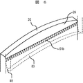
図6において実施例2を示す。本実施例では、第2段静翼3とダイアフラム5の下流側係合部において、ダイアフラムフック32のシール面より外周側に勾配39を設けた。さらに静翼フック33のシール面より内周に勾配40を設けている。具体的には、この勾配はタービン回転軸の垂直方向から任意の角度だけ壁面が傾斜した形状である。このように形成させてもシール面61b(図6の斜線部)は実質上帯状に形成されるため、下流側係合部におけるシール空気の不要なリークを低減することができる。また、ダイアフラムフックまたは静翼フックのうちの一方に段差を形成し、もう一方に勾配を形成させても効果に変わりはない。そして、勾配の形状は直線でも曲線でも効果に変わりなく、帯状にシール面を形成させれば、特に制限されない。
Example 2 is shown in FIG. In the present embodiment, a
図7は、ダイアフラムと静翼の段差形状の境界が折れ線となっている場合を示す。ダイアフラムと静翼との帯状シール面の境界は、できるかぎり直線状とするのが望ましい。しかし、連翼により直線状に形成させることが困難な場合、境界が折れ曲がり部45及び
46を有するような段差35b及び36bとしてシール面61c(図7の斜線部)を形成してもよい。静翼とダイアフラムとの係合構造のように、比較的シール部の平行度が保たれる場合にはシール効果を有する。さらに、シール面の境界を緩やかな曲線または複数の折れ曲がり部をもつ直線としても、多少のシール効果を得ることができる。
FIG. 7 shows a case where the boundary between the steps of the diaphragm and the stationary blade is a broken line. It is desirable that the boundary of the belt-like seal surface between the diaphragm and the stationary blade be as straight as possible. However, when it is difficult to form a straight line by the connecting blades, the sealing
以上、本実施例の静翼及びダイアフラム支持構造を用いることで、燃焼ガスの圧力比を高くしたガスタービンにおいても、静翼とダイアフラムで形成されるキャビティからリークする不要なシール空気を低減することができる。また、燃焼ガスの圧力比を高くしたことによるガスタービン熱効率の向上をダイアフラムからのリークによって低下させず、シール空気を確実に上流側へ供給して信頼性の高いガスタービンを提供することが可能である。 As described above, by using the stationary blade and diaphragm support structure of the present embodiment, even in a gas turbine having a high combustion gas pressure ratio, unnecessary seal air leaking from the cavity formed by the stationary blade and the diaphragm can be reduced. Can do. It is also possible to provide a highly reliable gas turbine by reliably supplying the seal air upstream without reducing the improvement in gas turbine thermal efficiency due to the increased pressure ratio of the combustion gas due to leakage from the diaphragm. It is.
1…第1段静翼、2…第1段動翼、3…第2段静翼、4…第2段動翼、5…ダイアフラム、6…ディスタントピース、7…第1段動翼ロータディスク、8…ディスクスペーサ、9…第2段動翼ロータディスク、10…スタブシャフト、11…キャビティ、12,13…シャンク部、14a,14b…ホイールスペース、15a,15b…シール空気、20…燃焼ガス、30,33…静翼フック、31,32…ダイアフラムフック、35,35b,36,36b…段差、37,38…境界、39,40…勾配、45,46…折れ曲がり部、50…固定ピン、51…ピン穴、52…ギャップ、60,61,61b…シール面、63,64…線接触シール部、70…作用力、80,81,95…矢印、90,91…孔、92…冷媒流路、93…外筒、94…冷却媒体。
DESCRIPTION OF SYMBOLS 1 ... 1st stage stationary blade, 2 ... 1st stage moving blade, 3 ... 2nd stage stationary blade, 4 ... 2nd stage moving blade, 5 ... Diaphragm, 6 ... Distant piece, 7 ... 1st stage moving blade rotor disk, 8 ... Disc spacer, 9 ... 2nd stage rotor rotor disk, 10 ... Stub shaft, 11 ... Cavity, 12, 13 ... Shank, 14a, 14b ... Wheel space, 15a, 15b ... Seal air, 20 ... Combustion gas, 30, 33 ... Static blade hook, 31, 32 ... Diaphragm hook, 35, 35b, 36, 36b ... Step, 37,38 ... Boundary, 39,40 ... Gradient, 45,46 ... Bent part, 50 ... Fixed pin, 51 ... Pin Hole, 52 ... Gap, 60, 61, 61b ... Seal surface, 63, 64 ... Line contact seal part, 70 ... Working force, 80, 81, 95 ... Arrow, 90, 91 ... Hole, 92 ... Refrigerant flow path, 93 ...
Claims (11)
前記シール手段と前記静翼とを係合する係合部を前記燃焼ガスが流れる方向で上流側から下流側にかけて複数個備え、
該係合部のうち上流側係合部の接触面がタービン回転軸を中心とする円の円周方向に形成されるように設けられ、下流側係合部の接触面が、前記シール手段と前記静翼との径方向の変位に対応可能なようにタービン回転軸と交差する方向に形成されるように設けられたことを特徴とするガスタービン。 A stationary blade and a stationary blade provided in a flow path of the combustion gas flowing in a downstream direction on the gas path outlet side inside a turbine to which combustion gas generated by mixing and burning combustion air and fuel is supplied A gas turbine having sealing means engaged with the gas turbine,
A plurality of engaging portions for engaging the sealing means and the stationary blades from the upstream side to the downstream side in the direction in which the combustion gas flows;
The contact surface of the upstream engagement portion of the engagement portions is provided so as to be formed in the circumferential direction of a circle centering on the turbine rotation axis, and the contact surface of the downstream engagement portion is connected to the sealing means. A gas turbine, wherein the gas turbine is provided so as to be formed in a direction intersecting with a turbine rotation axis so as to correspond to a radial displacement with respect to the stationary blade .
該下流側係合部の接触面では前記シール手段が前記静翼の上流側に位置することを特徴とするガスタービン。The gas turbine according to claim 1, wherein the seal means is located upstream of the stationary blade on the contact surface of the downstream engagement portion.
前記ダイアフラムと前記静翼とを係合する係合部を前記燃焼ガスが流れる方向で上流側から下流側にかけて複数個備え、
該係合部のうち上流側係合部の接触面がタービン回転軸を中心とする円の円周方向に形成されるように設けられた静翼フック及びダイアフラムフックと、下流側係合部の接触面が前記ダイアフラムと前記静翼との径方向の変位に対応可能なようにタービン回転軸と交差する方向に形成されるように設けられた静翼フックとダイアフラムフックとを備え、かつ、下流側の該静翼フック下面と該ダイアフラムフック上面とが接触することを特徴とするガスタービン。 A compressor that generates compressed air, a combustor that mixes and burns the compressed air and fuel, a turbine that is rotationally driven by combustion gas discharged from the combustor, and a turbine rotor that rotates with a casing inside the turbine A gas path through which the combustion gas flows is formed, and a stationary blade provided in a flow path of the combustion gas flowing in the downstream direction on the gas path outlet side, and a diaphragm engaged with the stationary blade, An upstream wheel space and a downstream wheel space are formed between the rotor blades, communicate with the upstream wheel space and the downstream wheel space, and supply a cooling medium in the diaphragm to the upstream wheel space and the downstream wheel space. A gas turbine provided with holes on the upstream and downstream sides of the diaphragm,
A plurality of engaging portions that engage the diaphragm and the stationary blade are provided from the upstream side to the downstream side in the direction in which the combustion gas flows,
Among the engaging portions, a stationary blade hook and a diaphragm hook provided so that the contact surface of the upstream engaging portion is formed in the circumferential direction of a circle centering on the turbine rotation axis, and the downstream engaging portion A stationary blade hook and a diaphragm hook provided so that a contact surface may be formed in a direction intersecting with a turbine rotation axis so as to correspond to a radial displacement between the diaphragm and the stationary blade; A gas turbine characterized in that the lower surface of the stationary blade hook and the upper surface of the diaphragm hook are in contact with each other.
該静翼フックと該ダイアフラムフックのどちらか一方に、前記接触面と前記接触面からタービン回転軸方向にずれた平面とで形成された段差形状で面接触させることを特徴とするガスタービン。 The gas turbine according to claim 1 , wherein
A gas turbine characterized in that either one of the stationary blade hook and the diaphragm hook is brought into surface contact with a stepped shape formed by the contact surface and a plane deviated from the contact surface in the turbine rotation axis direction.
前記下流側係合部は前記静翼フックと前記ダイアフラムフックとを固定ピンで係合し、
前記静翼フックに設けられた孔径が前記固定ピンの直径より大きいことを特徴とするガスタービン。 The gas turbine according to claim 1 , wherein
The downstream engaging portion engages the stationary blade hook and the diaphragm hook with a fixing pin,
A gas turbine characterized in that a hole diameter provided in the stationary blade hook is larger than a diameter of the fixing pin.
前記下流側係合部を構成する静翼フックと該静翼フックがダイアフラムフックに接触する接触部、及び該ダイアフラムフックと該ダイアフラムフックが前記静翼フックに接触する接触部がそれぞれ一体部品で形成されることを特徴とするガスタービン。 The gas turbine according to claim 1 , wherein
The stationary blade hook constituting the downstream engaging portion, the contact portion where the stationary blade hook contacts the diaphragm hook, and the contact portion where the diaphragm hook and the diaphragm hook contact the stationary blade hook are formed as an integral part, respectively. A gas turbine.
上流側係合部に設けられた静翼フックとダイアフラムフック間に軸方向の間隙を有することを特徴とするガスタービン。 The gas turbine according to claim 1 , wherein
A gas turbine comprising an axial gap between a stationary blade hook and a diaphragm hook provided in an upstream engaging portion.
該静翼フックと該ダイアフラムフックのどちらか一方に、前記タービン回転軸の垂直方向より任意の角度だけ壁面が傾斜した勾配を設けることを特徴とするガスタービン。 The gas turbine according to claim 1 , wherein
A gas turbine characterized in that either one of the stationary blade hook and the diaphragm hook is provided with a gradient whose wall surface is inclined at an arbitrary angle from a direction perpendicular to the turbine rotation axis.
前記係合部を上流側及び下流側にそれぞれ1箇所ずつ設けることを特徴とするガスタービン。 The gas turbine according to claim 1 , wherein
The gas turbine according to claim 1, wherein each of the engaging portions is provided on each of an upstream side and a downstream side.
前記シール手段と前記静翼とを係合する係合部を前記燃焼ガスが流れる方向で上流側から下流側にかけて複数個備えた係合部のうち、下流側係合部は前記シール手段と前記静翼との径方向の変位に対応可能なようにタービン回転軸と交差する方向に面接触され、
前記静翼の内部から導かれた冷却媒体を前記キャビティに供給し、前記シール手段の上流側に流すことを特徴とするガスタービンの冷却方法。 A stationary blade and a stationary blade provided in a flow path of the combustion gas flowing in a downstream direction on the gas path outlet side inside a turbine to which combustion gas generated by mixing and burning combustion air and fuel is supplied A gas turbine cooling method in which a sealing means engaged with the stationary blade is installed, and a cavity is formed by the stationary blade and the sealing means,
Of the engagement portion provided with a plurality of engaging portions from the upstream side in the direction of the flow of combustion gas to a downstream side for engaging said vane and said sealing means, the downstream-side engagement portion and the said sealing means Surface contact is made in a direction intersecting with the turbine rotation axis so as to correspond to radial displacement with the stationary blade ,
A cooling method for a gas turbine, characterized in that a cooling medium guided from the inside of the stationary blade is supplied to the cavity and flows to the upstream side of the sealing means.
前記シール手段と前記静翼とを係合する係合部を前記燃焼ガスが流れる方向で上流側から下流側にかけて複数個備えた係合部のうち、上流側係合部はタービン回転軸を中心とする円の円周方向に面接触され、下流側係合部は前記シール手段と前記静翼との径方向の変位に対応可能なようにタービン回転軸と交差する方向に面接触され、
前記静翼の内部から導かれた冷却媒体を前記キャビティに供給し、前記シール手段の上流側に流すことを特徴とするガスタービンの冷却方法。 A stationary blade and a stationary blade provided in a flow path of the combustion gas flowing in a downstream direction on the gas path outlet side inside a turbine to which combustion gas generated by mixing and burning combustion air and fuel is supplied A gas turbine cooling method in which a sealing means engaged with the stationary blade is installed, and a cavity is formed by the stationary blade and the sealing means,
Of the engagement portions provided from the upstream side to the downstream side in the direction in which the combustion gas flows, the upstream engagement portion is centered on the turbine rotation shaft. And the downstream engagement portion is in surface contact in a direction intersecting the turbine rotation axis so as to be able to cope with radial displacement between the sealing means and the stationary blade ,
A cooling method for a gas turbine, characterized in that a cooling medium guided from the inside of the stationary blade is supplied to the cavity and flows to the upstream side of the sealing means.
Priority Applications (6)
| Application Number | Priority Date | Filing Date | Title |
|---|---|---|---|
| JP2004200005A JP4412081B2 (en) | 2004-07-07 | 2004-07-07 | Gas turbine and gas turbine cooling method |
| US11/174,555 US7507069B2 (en) | 2004-07-07 | 2005-07-06 | Gas turbine and gas turbine cooling method |
| EP05014770A EP1614862B1 (en) | 2004-07-07 | 2005-07-07 | Gas turbine and gas turbine cooling and sealing method |
| DE602005003510T DE602005003510T2 (en) | 2004-07-07 | 2005-07-07 | Gas turbine and method for cooling and sealing a gas turbine |
| US12/366,085 US7950897B2 (en) | 2004-07-07 | 2009-02-05 | Gas turbine and gas turbine cooling method |
| US12/405,802 US7909564B2 (en) | 2004-07-07 | 2009-03-17 | Gas turbine and gas turbine cooling method |
Applications Claiming Priority (1)
| Application Number | Priority Date | Filing Date | Title |
|---|---|---|---|
| JP2004200005A JP4412081B2 (en) | 2004-07-07 | 2004-07-07 | Gas turbine and gas turbine cooling method |
Publications (2)
| Publication Number | Publication Date |
|---|---|
| JP2006022682A JP2006022682A (en) | 2006-01-26 |
| JP4412081B2 true JP4412081B2 (en) | 2010-02-10 |
Family
ID=35207764
Family Applications (1)
| Application Number | Title | Priority Date | Filing Date |
|---|---|---|---|
| JP2004200005A Active JP4412081B2 (en) | 2004-07-07 | 2004-07-07 | Gas turbine and gas turbine cooling method |
Country Status (4)
| Country | Link |
|---|---|
| US (3) | US7507069B2 (en) |
| EP (1) | EP1614862B1 (en) |
| JP (1) | JP4412081B2 (en) |
| DE (1) | DE602005003510T2 (en) |
Families Citing this family (43)
| Publication number | Priority date | Publication date | Assignee | Title |
|---|---|---|---|---|
| US20080145208A1 (en) * | 2006-12-19 | 2008-06-19 | General Electric Company | Bullnose seal turbine stage |
| US7578653B2 (en) * | 2006-12-19 | 2009-08-25 | General Electric Company | Ovate band turbine stage |
| US20110189000A1 (en) * | 2007-05-01 | 2011-08-04 | General Electric Company | System for regulating a cooling fluid within a turbomachine |
| WO2009074355A1 (en) * | 2007-12-10 | 2009-06-18 | Siemens Aktiengesellschaft | Axial turbo machine having reduced gap leakage |
| US8235652B2 (en) * | 2007-12-29 | 2012-08-07 | General Electric Company | Turbine nozzle segment |
| US8043044B2 (en) * | 2008-09-11 | 2011-10-25 | General Electric Company | Load pin for compressor square base stator and method of use |
| US8277172B2 (en) * | 2009-03-23 | 2012-10-02 | General Electric Company | Apparatus for turbine engine cooling air management |
| US8142141B2 (en) * | 2009-03-23 | 2012-03-27 | General Electric Company | Apparatus for turbine engine cooling air management |
| US8434994B2 (en) * | 2009-08-03 | 2013-05-07 | General Electric Company | System and method for modifying rotor thrust |
| DE102009042029A1 (en) * | 2009-09-17 | 2011-03-24 | Mtu Aero Engines Gmbh | Blade ring for flow machine, particularly for gas turbine, has hardened reinforcement on inner shroud, where reinforcement is closed in circumferential direction |
| JP4815536B2 (en) * | 2010-01-12 | 2011-11-16 | 川崎重工業株式会社 | Gas turbine engine seal structure |
| US9133732B2 (en) * | 2010-05-27 | 2015-09-15 | Siemens Energy, Inc. | Anti-rotation pin retention system |
| US9145771B2 (en) | 2010-07-28 | 2015-09-29 | United Technologies Corporation | Rotor assembly disk spacer for a gas turbine engine |
| US8591180B2 (en) * | 2010-10-12 | 2013-11-26 | General Electric Company | Steam turbine nozzle assembly having flush apertures |
| RU2548226C2 (en) * | 2010-12-09 | 2015-04-20 | Альстом Текнолоджи Лтд | Fluid medium flow unit, in particular, turbine with axially passing heated gas flow |
| US8979488B2 (en) * | 2011-03-23 | 2015-03-17 | General Electric Company | Cast turbine casing and nozzle diaphragm preforms |
| CN103502577B (en) * | 2011-04-19 | 2015-06-24 | 三菱日立电力系统株式会社 | Turbine stator vane and gas turbine |
| US9062557B2 (en) * | 2011-09-07 | 2015-06-23 | Siemens Aktiengesellschaft | Flow discourager integrated turbine inter-stage U-ring |
| US8944751B2 (en) * | 2012-01-09 | 2015-02-03 | General Electric Company | Turbine nozzle cooling assembly |
| US9011078B2 (en) * | 2012-01-09 | 2015-04-21 | General Electric Company | Turbine vane seal carrier with slots for cooling and assembly |
| EP2631433A1 (en) * | 2012-02-27 | 2013-08-28 | Siemens Aktiengesellschaft | Axially movable sealing device of a turbomachine |
| GB2520203A (en) * | 2012-09-06 | 2015-05-13 | Solar Turbines Inc | Gas turbine engine compressor undercut spacer |
| US20140064946A1 (en) * | 2012-09-06 | 2014-03-06 | Solar Turbines Incorporated | Gas turbine engine compressor undercut spacer |
| US9175566B2 (en) | 2012-09-26 | 2015-11-03 | Solar Turbines Incorporated | Gas turbine engine preswirler with angled holes |
| US9169729B2 (en) | 2012-09-26 | 2015-10-27 | Solar Turbines Incorporated | Gas turbine engine turbine diaphragm with angled holes |
| US20140083113A1 (en) * | 2012-09-27 | 2014-03-27 | General Electric Company | Flow control tab for turbine section flow cavity |
| US9327368B2 (en) * | 2012-09-27 | 2016-05-03 | United Technologies Corporation | Full ring inner air-seal with locking nut |
| EP2722486B1 (en) * | 2012-10-17 | 2016-12-07 | MTU Aero Engines AG | Seal holder for a stator assembly |
| WO2014134519A1 (en) * | 2013-02-28 | 2014-09-04 | United Technologies Corporation | Method and apparatus for collecting pre-diffuser airflow and routing it to combustor pre-swirlers |
| DE102013011350A1 (en) | 2013-07-08 | 2015-01-22 | Rolls-Royce Deutschland Ltd & Co Kg | Gas turbine with high pressure turbine cooling system |
| WO2015112227A2 (en) * | 2013-11-12 | 2015-07-30 | United Technologies Corporation | Multiple injector holes for gas turbine engine vane |
| WO2015191169A1 (en) * | 2014-06-12 | 2015-12-17 | General Electric Company | Shroud hanger assembly |
| EP2998517B1 (en) * | 2014-09-16 | 2019-03-27 | Ansaldo Energia Switzerland AG | Sealing arrangement at the interface between a combustor and a turbine of a gas turbine and gas turbine with such a sealing arrangement |
| ES2644335T3 (en) * | 2014-12-17 | 2017-11-28 | MTU Aero Engines AG | Refrigerant air supply device for a gas turbine |
| US10202857B2 (en) | 2015-02-06 | 2019-02-12 | United Technologies Corporation | Vane stages |
| US20180223683A1 (en) * | 2015-07-20 | 2018-08-09 | Siemens Energy, Inc. | Gas turbine seal arrangement |
| US10060280B2 (en) | 2015-10-15 | 2018-08-28 | United Technologies Corporation | Turbine cavity sealing assembly |
| US10519873B2 (en) * | 2016-04-06 | 2019-12-31 | General Electric Company | Air bypass system for rotor shaft cooling |
| GB201613926D0 (en) * | 2016-08-15 | 2016-09-28 | Rolls Royce Plc | Inter-stage cooling for a turbomachine |
| WO2020040747A1 (en) * | 2018-08-21 | 2020-02-27 | Siemens Aktiengesellschaft | Modular casing manifold for cooling fluids of gas turbine engine |
| JP7284737B2 (en) | 2020-08-06 | 2023-05-31 | 三菱重工業株式会社 | gas turbine vane |
| CN113202566B (en) * | 2021-04-19 | 2022-12-02 | 中国航发湖南动力机械研究所 | Turbine guide vane and gas turbine engine |
| US11692451B1 (en) * | 2022-03-28 | 2023-07-04 | Pratt & Whitney Canada Corp. | Aircraft engine with radial clearance between seal and deflector |
Family Cites Families (25)
| Publication number | Priority date | Publication date | Assignee | Title |
|---|---|---|---|---|
| US3871770A (en) * | 1973-06-04 | 1975-03-18 | Nuclear Data Inc | Hydrodynamic focusing method and apparatus |
| US4113406A (en) * | 1976-11-17 | 1978-09-12 | Westinghouse Electric Corp. | Cooling system for a gas turbine engine |
| DE3003470C2 (en) | 1980-01-31 | 1982-02-25 | MTU Motoren- und Turbinen-Union München GmbH, 8000 München | Turbine guide vane suspension for gas turbine jet engines |
| JPS6237204A (en) | 1985-03-28 | 1987-02-18 | Sumitomo Rubber Ind Ltd | Tire for aircraft |
| US4666368A (en) * | 1986-05-01 | 1987-05-19 | General Electric Company | Swirl nozzle for a cooling system in gas turbine engines |
| US4820116A (en) * | 1987-09-18 | 1989-04-11 | United Technologies Corporation | Turbine cooling for gas turbine engine |
| US4930980A (en) | 1989-02-15 | 1990-06-05 | Westinghouse Electric Corp. | Cooled turbine vane |
| US5215435A (en) * | 1991-10-28 | 1993-06-01 | General Electric Company | Angled cooling air bypass slots in honeycomb seals |
| US5253976A (en) * | 1991-11-19 | 1993-10-19 | General Electric Company | Integrated steam and air cooling for combined cycle gas turbines |
| US5749584A (en) * | 1992-11-19 | 1998-05-12 | General Electric Company | Combined brush seal and labyrinth seal segment for rotary machines |
| US6454945B1 (en) * | 1995-06-16 | 2002-09-24 | University Of Washington | Microfabricated devices and methods |
| US5716852A (en) * | 1996-03-29 | 1998-02-10 | University Of Washington | Microfabricated diffusion-based chemical sensor |
| US6120666A (en) * | 1996-09-26 | 2000-09-19 | Ut-Battelle, Llc | Microfabricated device and method for multiplexed electrokinetic focusing of fluid streams and a transport cytometry method using same |
| US5858187A (en) * | 1996-09-26 | 1999-01-12 | Lockheed Martin Energy Systems, Inc. | Apparatus and method for performing electrodynamic focusing on a microchip |
| US5749701A (en) * | 1996-10-28 | 1998-05-12 | General Electric Company | Interstage seal assembly for a turbine |
| US6159739A (en) * | 1997-03-26 | 2000-12-12 | University Of Washington | Device and method for 3-dimensional alignment of particles in microfabricated flow channels |
| JP2961089B2 (en) | 1997-06-05 | 1999-10-12 | 三菱重工業株式会社 | Gas turbine one-stage stationary blade seal structure |
| US6045134A (en) * | 1998-02-04 | 2000-04-04 | General Electric Co. | Combined labyrinth and brush seals for rotary machines |
| US6067157A (en) * | 1998-10-09 | 2000-05-23 | University Of Washington | Dual large angle light scattering detection |
| WO2000070080A1 (en) * | 1999-05-17 | 2000-11-23 | Caliper Technologies Corp. | Focusing of microparticles in microfluidic systems |
| US7601270B1 (en) * | 1999-06-28 | 2009-10-13 | California Institute Of Technology | Microfabricated elastomeric valve and pump systems |
| JP2003505260A (en) * | 1999-07-23 | 2003-02-12 | ザ ボード オブ トラスティーズ オブ ザ ユニバーシテイ オブ イリノイ | Micromachined device and method of manufacturing the same |
| US6382228B1 (en) * | 2000-08-02 | 2002-05-07 | Honeywell International Inc. | Fluid driving system for flow cytometry |
| US6558114B1 (en) * | 2000-09-29 | 2003-05-06 | Siemens Westinghouse Power Corporation | Gas turbine with baffle reducing hot gas ingress into interstage disc cavity |
| US6854736B2 (en) * | 2003-03-26 | 2005-02-15 | Siemens Westinghouse Power Corporation | Seal assembly for a rotary machine |
-
2004
- 2004-07-07 JP JP2004200005A patent/JP4412081B2/en active Active
-
2005
- 2005-07-06 US US11/174,555 patent/US7507069B2/en active Active
- 2005-07-07 DE DE602005003510T patent/DE602005003510T2/en active Active
- 2005-07-07 EP EP05014770A patent/EP1614862B1/en active Active
-
2009
- 2009-02-05 US US12/366,085 patent/US7950897B2/en active Active
- 2009-03-17 US US12/405,802 patent/US7909564B2/en active Active
Also Published As
| Publication number | Publication date |
|---|---|
| DE602005003510D1 (en) | 2008-01-10 |
| JP2006022682A (en) | 2006-01-26 |
| US7909564B2 (en) | 2011-03-22 |
| US20060034685A1 (en) | 2006-02-16 |
| EP1614862A1 (en) | 2006-01-11 |
| US20090185896A1 (en) | 2009-07-23 |
| EP1614862B1 (en) | 2007-11-28 |
| US7950897B2 (en) | 2011-05-31 |
| US20090196738A1 (en) | 2009-08-06 |
| US7507069B2 (en) | 2009-03-24 |
| DE602005003510T2 (en) | 2008-10-30 |
Similar Documents
| Publication | Publication Date | Title |
|---|---|---|
| JP4412081B2 (en) | Gas turbine and gas turbine cooling method | |
| US7686569B2 (en) | Blade clearance system for a turbine engine | |
| JP5547997B2 (en) | Spring design for active and passive retractable seals | |
| US8845284B2 (en) | Apparatus and system for sealing a turbine rotor | |
| JP6072930B2 (en) | Belly seal with underwrap end | |
| US9677669B2 (en) | Shaft seal device and rotary machine | |
| US20170298813A1 (en) | Variable nozzle unit and variable-capacity supercharger | |
| JP2004197741A (en) | Method and apparatus for sealing variable vane assembly of gas turbine engine | |
| JP2008184971A (en) | Variable displacement type supercharger | |
| EP2559860A2 (en) | Turbomachine seal assembly | |
| JP2009203948A (en) | Seal device, seal method and gas turbine having seal device | |
| US20060010880A1 (en) | Gas turbine engine with seal assembly | |
| JP2018035717A (en) | Seal device segment, turbine rotor including the same, and turbine | |
| US9617920B2 (en) | Sealing arrangement for a nozzle guide vane and gas turbine | |
| JP5926122B2 (en) | Sealing device | |
| WO2022113619A1 (en) | Supercharger | |
| JP4460471B2 (en) | Gas turbine sealing device | |
| JP6969670B2 (en) | Supercharger | |
| JP4370232B2 (en) | Fluid machine with fluid seal mechanism | |
| CN114810221B (en) | Stator blade and inner ring supporting mechanism | |
| JP7317657B2 (en) | turbocharger | |
| JP7343362B2 (en) | supercharger | |
| JP2000274261A (en) | Gas turbine | |
| JP2013155680A (en) | Sealing device of gas turbine | |
| US8469656B1 (en) | Airfoil seal system for gas turbine engine |
Legal Events
| Date | Code | Title | Description |
|---|---|---|---|
| RD04 | Notification of resignation of power of attorney |
Free format text: JAPANESE INTERMEDIATE CODE: A7424 Effective date: 20060424 |
|
| A621 | Written request for application examination |
Free format text: JAPANESE INTERMEDIATE CODE: A621 Effective date: 20060927 |
|
| A131 | Notification of reasons for refusal |
Free format text: JAPANESE INTERMEDIATE CODE: A131 Effective date: 20090303 |
|
| A521 | Request for written amendment filed |
Free format text: JAPANESE INTERMEDIATE CODE: A523 Effective date: 20090427 |
|
| TRDD | Decision of grant or rejection written | ||
| A01 | Written decision to grant a patent or to grant a registration (utility model) |
Free format text: JAPANESE INTERMEDIATE CODE: A01 Effective date: 20091027 |
|
| A01 | Written decision to grant a patent or to grant a registration (utility model) |
Free format text: JAPANESE INTERMEDIATE CODE: A01 |
|
| A61 | First payment of annual fees (during grant procedure) |
Free format text: JAPANESE INTERMEDIATE CODE: A61 Effective date: 20091109 |
|
| FPAY | Renewal fee payment (event date is renewal date of database) |
Free format text: PAYMENT UNTIL: 20121127 Year of fee payment: 3 |
|
| R151 | Written notification of patent or utility model registration |
Ref document number: 4412081 Country of ref document: JP Free format text: JAPANESE INTERMEDIATE CODE: R151 |
|
| FPAY | Renewal fee payment (event date is renewal date of database) |
Free format text: PAYMENT UNTIL: 20121127 Year of fee payment: 3 |
|
| FPAY | Renewal fee payment (event date is renewal date of database) |
Free format text: PAYMENT UNTIL: 20131127 Year of fee payment: 4 |
|
| S111 | Request for change of ownership or part of ownership |
Free format text: JAPANESE INTERMEDIATE CODE: R313111 |
|
| R350 | Written notification of registration of transfer |
Free format text: JAPANESE INTERMEDIATE CODE: R350 |
|
| R250 | Receipt of annual fees |
Free format text: JAPANESE INTERMEDIATE CODE: R250 |
|
| R250 | Receipt of annual fees |
Free format text: JAPANESE INTERMEDIATE CODE: R250 |
|
| R250 | Receipt of annual fees |
Free format text: JAPANESE INTERMEDIATE CODE: R250 |
|
| R250 | Receipt of annual fees |
Free format text: JAPANESE INTERMEDIATE CODE: R250 |
|
| R250 | Receipt of annual fees |
Free format text: JAPANESE INTERMEDIATE CODE: R250 |
|
| R250 | Receipt of annual fees |
Free format text: JAPANESE INTERMEDIATE CODE: R250 |
|
| R250 | Receipt of annual fees |
Free format text: JAPANESE INTERMEDIATE CODE: R250 |
|
| R250 | Receipt of annual fees |
Free format text: JAPANESE INTERMEDIATE CODE: R250 |
|
| R250 | Receipt of annual fees |
Free format text: JAPANESE INTERMEDIATE CODE: R250 |
|
| R250 | Receipt of annual fees |
Free format text: JAPANESE INTERMEDIATE CODE: R250 |