JP4410848B2 - Cell culture equipment - Google Patents
Cell culture equipment Download PDFInfo
- Publication number
- JP4410848B2 JP4410848B2 JP2004506446A JP2004506446A JP4410848B2 JP 4410848 B2 JP4410848 B2 JP 4410848B2 JP 2004506446 A JP2004506446 A JP 2004506446A JP 2004506446 A JP2004506446 A JP 2004506446A JP 4410848 B2 JP4410848 B2 JP 4410848B2
- Authority
- JP
- Japan
- Prior art keywords
- liquid
- container
- opening
- wall
- collector
- Prior art date
- Legal status (The legal status is an assumption and is not a legal conclusion. Google has not performed a legal analysis and makes no representation as to the accuracy of the status listed.)
- Expired - Fee Related
Links
Images


Classifications
-
- C—CHEMISTRY; METALLURGY
- C12—BIOCHEMISTRY; BEER; SPIRITS; WINE; VINEGAR; MICROBIOLOGY; ENZYMOLOGY; MUTATION OR GENETIC ENGINEERING
- C12M—APPARATUS FOR ENZYMOLOGY OR MICROBIOLOGY; APPARATUS FOR CULTURING MICROORGANISMS FOR PRODUCING BIOMASS, FOR GROWING CELLS OR FOR OBTAINING FERMENTATION OR METABOLIC PRODUCTS, i.e. BIOREACTORS OR FERMENTERS
- C12M25/00—Means for supporting, enclosing or fixing the microorganisms, e.g. immunocoatings
- C12M25/06—Plates; Walls; Drawers; Multilayer plates
-
- C—CHEMISTRY; METALLURGY
- C12—BIOCHEMISTRY; BEER; SPIRITS; WINE; VINEGAR; MICROBIOLOGY; ENZYMOLOGY; MUTATION OR GENETIC ENGINEERING
- C12M—APPARATUS FOR ENZYMOLOGY OR MICROBIOLOGY; APPARATUS FOR CULTURING MICROORGANISMS FOR PRODUCING BIOMASS, FOR GROWING CELLS OR FOR OBTAINING FERMENTATION OR METABOLIC PRODUCTS, i.e. BIOREACTORS OR FERMENTERS
- C12M29/00—Means for introduction, extraction or recirculation of materials, e.g. pumps
Description
本発明は、手で取り扱うことなく、さまざまな培地での細胞の処理を可能にする、細胞培養装置に関するものである。 The present invention relates to a cell culture apparatus that enables cells to be treated in various media without being handled by hand.
仏国特許発明第2659347号明細書(1991年9月13日公開)には、細胞を入れるための容器を備えた細胞培養装置について記載されている。容器は、細胞の直径よりも小さな幅を有する溝をその間に形成するよう間隔を置いて並置された二枚のガラス板から形成された水平支持体を備えている。処理される細胞は溝に置かれる。この容器は、液体培養培地または液体刺激培地を入れるためのものである。さまざまな液体培地が、細胞を支える壁の上に位置づけられた個別の管によって容器に順次注入される。容器に注入された液体の一部は、壁の下に位置する一本または複数本の管によって排出される。この液体の他の部分は溢れることによって排出される。 French patent invention No. 2659347 (published on September 13, 1991) describes a cell culture device provided with a container for containing cells. The container comprises a horizontal support formed from two glass plates juxtaposed spaced apart to form a groove therebetween having a width smaller than the diameter of the cell. Cells to be processed are placed in the groove. This container is for containing a liquid culture medium or a liquid stimulation medium. Various liquid media are sequentially injected into the container by individual tubes positioned over the walls that support the cells. Part of the liquid injected into the container is drained by one or more tubes located below the wall. The other part of the liquid is discharged by overflowing.
この装置において細胞は、一本または複数本の排出導管による液体培地の吸引によって引き起こされる低圧によって溝に維持される。 In this device, the cells are maintained in the groove by a low pressure caused by aspiration of the liquid medium by one or more discharge conduits.
かかる装置はとくに卵母細胞、受精卵または胚などの培養のためのものである。 Such devices are especially for culturing oocytes, fertilized eggs or embryos.
とくに、該装置は実験用の卵母細胞の活性化に用いることができ、この活性化は胚のその後の良好な発生に必要なものである。この活性化を引き起こすために、容器に培養培地を注入し、活性化させる細胞をこの培養培地の中に置く。次に、イオンが豊富な培地を排出し、また同時にCa2+イオンを含む刺激培地に置換する。培養培地が完全に排出され、刺激培地に置換されると、細胞は、該細胞の細胞膜の一時的な電気透過化と細胞内へのCa2+イオンの透過を引き起こす、電界刺激にかけられる。ついで、今度は刺激培地が排出され、培養培地に置換される。これらの過程は、細胞が、それらの活性化を引き起こす一連の制御されたカルシウム刺激の影響を受けやすくするために、複数回繰り返される。 In particular, the device can be used for the activation of laboratory oocytes, which activation is necessary for the subsequent successful development of the embryo. To cause this activation, the culture medium is poured into the container and the cells to be activated are placed in this culture medium. Next, the medium rich in ions is discharged and at the same time replaced with a stimulation medium containing Ca 2+ ions. When the culture medium is completely drained and replaced with the stimulation medium, the cells are subjected to electric field stimulation that causes temporary electropermeabilization of the cell membrane of the cells and penetration of Ca 2+ ions into the cells. The stimulation medium is then drained and replaced with the culture medium. These processes are repeated multiple times to make the cells susceptible to a series of controlled calcium stimuli that cause their activation.
この装置の利点は、それらを手で取り扱うことなく、さまざまな培地での細胞の処理を可能にすることである。 The advantage of this device is that it allows the treatment of cells with various media without having to handle them by hand.
しかしながら、この種の装置が有する問題は、ある培地から別の培地への置換にかかる時間が比較的長く、容器内の培地の交換頻度が制限されることである。 However, the problem with this type of apparatus is that the time required for replacement from one medium to another is relatively long and the replacement frequency of the medium in the container is limited.
例えば、細胞活性化に装置が使用される場合、培養培地を刺激培地に置換するために刺激培地を注入する最低時間(約40秒)が必要である。実際、この最低時間は刺激培地による細胞の十分な洗浄を保証するものである。 For example, if the device is used for cell activation, a minimum time (approximately 40 seconds) of injecting the stimulation medium is required to replace the culture medium with the stimulation medium. In fact, this minimum time guarantees sufficient washing of the cells with the stimulation medium.
洗浄の最低時間が守られない場合、刺激培地は培養培地に由来する残留イオンを含むこととなる。電界にかけると、これらのイオンは膜貫通型のイオン電流を誘導し、細胞破壊が引き起こされる。 If the minimum washing time is not observed, the stimulation medium will contain residual ions derived from the culture medium. When subjected to an electric field, these ions induce a transmembrane ion current, causing cell destruction.
洗浄に関連するもう一つの問題は、細胞をイオン力の小さい刺激培地に長時間晒すと、細胞の平衡を乱し、該細胞を有害作用に晒すこととなるということである。細胞の生存を守るには、したがって、細胞の洗浄時間の短縮が必要となる。
本発明の一つの目的は、細胞が置かれている培地の迅速な置換を可能にする細胞培養装置を提供することである。 One object of the present invention is to provide a cell culture device that allows rapid replacement of the medium in which the cells are placed.
溢れ出すことによる液体の排出は、不規則な現象であることがわかった。実際、容器に液体を注入する間、液体の自由表面は室の上面を超えて上昇し、液体の表面は凸状のメニスカスの形を取る。この現象は、液体の表面に作用し、室の垂直な壁に対するこの液体の付着力に作用する、表面張力に関連する。一方の表面張力に関連する力と、他方の比重に関連する力の間の平衡が崩れるには、室の縁の上にある液体の高低差が臨界値に達しなければならない。この平衡の崩れは、室の壁の上から余分な液体の流出を引き起こす。 The discharge of liquid due to overflowing was found to be an irregular phenomenon. In fact, while injecting liquid into the container, the free surface of the liquid rises above the upper surface of the chamber and the surface of the liquid takes the form of a convex meniscus. This phenomenon is related to the surface tension that acts on the surface of the liquid and affects the adhesion of this liquid to the vertical walls of the chamber. In order for the balance between the force related to one surface tension and the force related to the other specific gravity to break, the height difference of the liquid above the chamber edge must reach a critical value. This imbalance causes excess liquid to escape from above the chamber walls.
結果、溢れ出すことによる液体の排出は、不連続で予測不可能な仕方で起こる。とりわけ、ある培地を他の培地に置換する段階で、置換される培地が排出されないことが起こり得る。したがって、この置換の段階の際の細胞の洗浄が保証されないため、この排出は満足できるものではない。 As a result, liquid discharge due to overflow occurs in a discontinuous and unpredictable manner. In particular, it is possible that the medium to be replaced is not discharged at the stage of replacing one medium with another medium. Therefore, this drainage is not satisfactory since washing of the cells during this replacement step is not guaranteed.
他方で、もう一つの問題は、この不連続の流出が液体の中に連続した衝撃波を発生させることである。これらの衝撃波は支持体にある細胞を移動させてしまう。 On the other hand, another problem is that this discontinuous spill generates a continuous shock wave in the liquid. These shock waves move the cells on the support.
細胞は、支持体要素の溝に沿って、細胞が集まる室の中心に向かって移動する傾向がある。細胞は互いに押し付けられる。細胞間の空間の減少は、それぞれの細胞の周縁での洗浄の効果を変化させる。 The cells tend to move along the grooves of the support element toward the center of the chamber where the cells gather. The cells are pressed against each other. The reduction in the space between cells changes the effect of washing at the periphery of each cell.
最後に、さらにもう一つの問題は、培養培地と周囲の気体との間の界面が、表面現象の場となることである。原子または分子の膜が、液体の自由表面上に形成される。これらの膜は、容器内の培地を他のものへ置換しても新しいものにならない。 Finally, yet another problem is that the interface between the culture medium and the surrounding gas becomes a surface phenomenon field. A film of atoms or molecules is formed on the free surface of the liquid. These membranes do not become new when the medium in the container is replaced with another.
細胞に電界刺激を加えるためにこの培養装置が使用される場合、これらの膜は、電極の間に伝導性のブリッジを構成する可能性がある。これらの伝導性のブリッジは、電極間に短絡を形成する。結果、加えられた電界刺激の効果が大幅に減じる。 When this culture device is used to apply electric field stimulation to cells, these membranes can constitute a conductive bridge between the electrodes. These conductive bridges form a short circuit between the electrodes. As a result, the effect of the applied electric field stimulation is greatly reduced.
この不都合に対処するために、本発明は、細胞を入れる容器を備えた、とりわけ細胞培養のための装置を提案するものであり、前記容器は少なくとも一つの液体注入導管を備え、容器内の液体の表面は空気と自由に接触しており、そして、液体の自由表面との間に少なくとも一つの液体ブリッジを形成させるのに適したコレクタ要素を有し、コレクタ要素が、容器内の液体の自由表面の高さにほぼ位置する開口部を有し、開口部が、液体表面の膜を液体ブリッジを介して引っ張る空気の流れを吸い込む様に低圧に維持されていることを特徴とする。 In order to address this disadvantage, the present invention proposes an apparatus for cell culture, in particular comprising a container for the cells, said container comprising at least one liquid injection conduit, the liquid in the container The surface of the substrate is in free contact with air and has a collector element suitable for forming at least one liquid bridge with the free surface of the liquid, the collector element being free of liquid in the container It has an opening substantially located at the level of the surface, and the opening is maintained at a low pressure so as to suck in an air flow that pulls the film on the liquid surface through the liquid bridge.
本発明による装置は、液体の自由表面とコレクタ要素の間にメニスカス形状の液体ブリッジを生み出すことを可能にする。このメニスカスは、容器内の液体の表面の表面張力を平衡効果によって調節する。 The device according to the invention makes it possible to create a meniscus-shaped liquid bridge between the free surface of the liquid and the collector element. This meniscus adjusts the surface tension of the surface of the liquid in the container by an equilibrium effect.
かかる装置は、空気の流れによって容器の余分な液体を連続的に除去し、それにより液体の水位を一定に保つことを可能にする。 Such a device makes it possible to continuously remove excess liquid in the container by the flow of air, thereby keeping the liquid level constant.
それはまた、容器の液体の表面の膜を常に新しいものにすることも可能にする。 It also makes it possible to keep the membrane on the liquid surface of the container constantly new.
本発明の一つの実施態様において、コレクタ要素は容器の壁の縁に位置し、その開口部は壁よりも後退している。 In one embodiment of the invention, the collector element is located at the edge of the container wall and its opening is recessed from the wall.
好適には、コレクタ要素の開口部の前に位置する縁の部分は、親水性物質で被覆されている。 Preferably, the edge portion located in front of the opening of the collector element is coated with a hydrophilic substance.
好適には、開口部は10と30μmの間に含まれる距離dだけ壁から後退している。 Preferably, the opening is retracted from the wall by a distance d comprised between 10 and 30 μm.
好適には、コレクタの開口部は細長い形状を有し、壁の縁に沿って長手方向に延びている。 Preferably, the collector opening has an elongated shape and extends longitudinally along the edge of the wall.
本発明の一つの実施態様において、開口部は2から4mm程度の長さを有する。 In one embodiment of the invention, the opening has a length on the order of 2 to 4 mm.
本発明の一つの実施態様において、開口部は0.15から0.30mm程度の高さを有する。 In one embodiment of the invention, the opening has a height on the order of 0.15 to 0.30 mm.
本発明の一つの実施態様において、コレクタ要素の開口部は、ほぼ長方形の形状を有する。 In one embodiment of the invention, the collector element opening has a generally rectangular shape.
有利には、装置は容器の壁の縁に沿って位置する複数のコレクタ要素を備えている。 Advantageously, the device comprises a plurality of collector elements located along the edge of the container wall.
本発明はまた、細胞を入れるための容器に入れられた液体の水位の調節方法に関するものであり、前記容器が少なくとも一つの液体注入導管を備え、容器内の液体の表面が空気と自由に接触しており、そして、液体の自由表面との間に少なくとも一つの液体ブリッジが形成され、液体ブリッジの近傍で空気の流れを吸い込むことで、空気の流れが液体表面の膜を、液体ブリッジを介して引っ張ることを特徴とする。 The invention also relates to a method for adjusting the level of a liquid contained in a container for containing cells, said container comprising at least one liquid injection conduit, wherein the surface of the liquid in the container is in free contact with air. And at least one liquid bridge is formed between the free surface of the liquid and the air flow is sucked in the vicinity of the liquid bridge so that the air flow passes through the liquid surface film through the liquid bridge. It is characterized by pulling.
その他の特徴および利点は、付属の図面を参照に、非制限的な例として挙げられた下記の説明を読むことによっても明らかになるだろう。 Other features and advantages will become apparent upon reading the following description given by way of non-limiting example with reference to the accompanying drawings.
図1は、本発明の一つの実施態様に従った細胞培養装置の一つの例を示した図である。 FIG. 1 is a diagram showing an example of a cell culture device according to one embodiment of the present invention.
図2は、図1の装置のコレクタの詳細図である。 FIG. 2 is a detailed view of the collector of the apparatus of FIG.
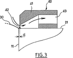
図3は、図2のコレクタの断面図である。 3 is a cross-sectional view of the collector of FIG.
図1において図示された細胞培養装置は、液体培地を入れるための室20を区切る壁11、12,13を備えた容器100を備えている。室は処理中の細胞の処理段階に対応する液体培地で満たされている。室20には、並置された二枚のガラス板101と102によって形成された水平支持体要素がある。ガラス板101と102は、容器の側面の壁11と12に嵌め込まれて維持されている。これらのガラス板101と102は、互いの間に間隔があいており、処理する卵母細胞(10)の直径より小さい幅を有する直線的な溝103が規定される。
The cell culture apparatus illustrated in FIG. 1 includes a
容器100はまた、溝103の両方向に縦に延びた電極111と112を備えている。
The
培養液体は、その口121、122、123、124、125、126が壁11、12と13に沿って規則的な間隔で位置した、一揃いの導管によって室20の上部に運ばれる。他方で、容器内の液体の一部は、排出導管104によって排出され、該排出導管は支持要素よりも低い高さに位置する。液体の流れは、卵母細胞10を低圧によって溝103に張り付いた状態で維持する。
The culture liquid is conveyed to the top of the
容器100内の液体の自由表面は、凸形の形状を有する分子膜30を形成する。この膜30は、親水基が流体に向かって位置し、疎水部分が外側の空気に向かって位置するように配向した分子の整列によって構成される。
The free surface of the liquid in the
分子膜30を除去し、室20内の余分な液体を吸収するために、培養装置は、室20の壁11の水平縁21に位置したコレクタ40を備えている。
In order to remove the
対称的に、装置は壁12または13の縁22または23(点線で示された位置)に位置したコレクタを備えることができる。
In contrast, the device can comprise a collector located at the
これらのコレクタ40は、室20の周囲に規則的な間隔で配置することができる。
These
図2は、図1の細胞培養装置のコレクタ40を更に詳細に示した図である。
FIG. 2 is a view showing the
このコレクタ40は、距離dだけ壁11から後退するように、容器の壁11の縁21に位置する。該コレクタは、壁11に沿って延びる長方形の開口部42を有する中空体41を備えるものである。この開口部は、長さがL=2mm、高さがl=0.2mmである。
This
室20内の液体の表面30と開口部42の垂直縁の間に、二つの液体ブリッジ51と52が形成される。これらの液体ブリッジ51と52は、開口部42の縁と接触する液体の表面30の変形(またはメニスカス)によって形成される。
Between the
コレクタ40はさらに図示されていない吸引装置に接続された排出導管43を備えている。この吸引装置は、コレクタ40内に含まれる空気を吸引することができる。この吸引は開口部42を通る空気循環を引き起こし、該循環は、容器内の液体の上部を液体ブリッジ51と52を介して引っ張るものである。結果、液体表面の分子膜30はコレクタを循環する空気によって常に引っ張られ、液体表面から除去される。
The
開口部の長さLは、容器に入れられた液体の毛管現象の長さk-1の少なくとも二倍以上となるように選択された。この特徴は、両サイドにおける二つのメニスカスの形成を、ひいては、液体によって開口部42が閉塞されないことを保証する。したがって、空気は常に開口部42を通って循環することができる。
The length L of the opening was selected to be at least twice as long as the capillary length k −1 of the liquid contained in the container. This feature ensures the formation of two meniscuses on both sides and thus that the
細胞処理に一般的に用いられる液体は、一般的に1mmと2mmの間に含まれる毛管現象の長さを有する。したがって開口部の長さLは、好適には約2から4mmである。 Liquids commonly used for cell treatment typically have a capillary action length comprised between 1 mm and 2 mm. Accordingly, the length L of the opening is preferably about 2 to 4 mm.
コレクタ40は、距離dだけ壁から後退したところに位置する。なぜなら、開口部は壁11に近すぎてはならないためであるが、近すぎる場合には、毛管力は開口部42を閉塞する単一の液体ブリッジを形成させ、そして室20内の液体を空にするであろう。
The
とは言え、開口部42は壁11から離れすぎてもならず、離れすぎた場合には、コレクタは液体にもはや何の作用も及ぼさないであろう。
Nevertheless, the
他方で、数ミクロンの距離dは、凹形のメニスカスを形成させる。ときに、凹形には複数の欠点がある:
・一方では、それは細胞10の近傍で、室20の底部に向かう表面張力を大きくし、そのため操作員による細胞の設置または採取がいっそう困難なものとなる。
・他方では、凹形は光の光学経路を変化させ、操作員による細胞の視覚化がいっそう困難なものとなる。
On the other hand, a distance d of a few microns forms a concave meniscus. Sometimes concave shapes have several drawbacks:
-On the one hand, it increases the surface tension towards the bottom of the
On the other hand, the concave shape changes the optical path of light, making it more difficult for the operator to visualize the cells.
結果として、安定した凸形のメニスカスを維持することが望ましい。距離dが好適には10と30μmの間に含まれるのは、このためである。 As a result, it is desirable to maintain a stable convex meniscus. This is why the distance d is preferably comprised between 10 and 30 μm.
この様に、図2に示したコレクタ40において、距離dは20μmである。
Thus, in the
好適には、容器の壁11、12と13の縁21、22と23は、親水性物質で被覆されているコレクタの開口部42の前をのぞいて、疎水性の物質で被覆されている。この被覆の処理は、コレクタ40の高さで液体ブリッジが始まることを助ける。
Preferably, the
図3において、コレクタ40は排出導管43に沿った断面図で示されている。吸引された空気の経路は矢印で示されている。
In FIG. 3, the
10 細胞
11、12、13 壁
100 容器
101、102 ガラス板
103 溝
111、112 電極
121、122、123、124、125、126 導管の口
20 室
21、22、23 壁の水平縁
30 液体の表面、分子膜
40 コレクタ
41 中空体
42 開口部
43 排出導管
51、52 液体ブリッジ
10
Claims (8)
前記容器(100)は、少なくとも一つの液体注入導管(121、122、123、124、125、126)を備え、
容器(100)内の液体の表面は空気と自由に接触しており、
そして、液体の自由表面との間に少なくとも一つの液体ブリッジ(51、52)を形成させるのに適したコレクタ要素(40)を有し、
該コレクタ要素(40)が、容器(100)内の液体の自由表面の高さに位置する開口部(42)を有し、
前記コレクタ要素(40)が、容器(100)の壁(11)の縁(21)に位置し、
前記開口部(42)が、壁(11)よりも後退し、10と30μmの間に含まれる距離(d)だけ壁(11)から後退し、
開口部(42)が、液体表面の膜(30)を液体ブリッジ(51、52)を介して引っ張る空気の流れを吸い込む様に低圧に維持されていることを特徴とする装置。With a container (100) to put the cell (10), a device for cell culture,
The container (100) comprises at least one liquid injection conduit (121, 122, 123, 124, 125, 126),
The surface of the liquid in the container (100) is in free contact with air,
And having a collector element (40) suitable for forming at least one liquid bridge (51, 52) with the free surface of the liquid;
Has the collector element (40) is an opening which position the height of the free surface of the liquid in the container (100) (42),
The collector element (40) is located at the edge (21) of the wall (11) of the container (100);
The opening (42) recedes from the wall (11) and recedes from the wall (11) by a distance (d) comprised between 10 and 30 μm;
A device characterized in that the opening (42) is maintained at a low pressure so as to draw in a flow of air that pulls the membrane (30) on the liquid surface through the liquid bridge (51, 52).
前記容器(100)が少なくとも一つの液体注入導管(121、122、123、124、125、126)を備え、
容器(100)内の液体の表面が空気と自由に接触しており、
そして、液体の自由表面との間に少なくとも一つの液体ブリッジ(51、52)を形成させるのに適したコレクタ要素(40)を有し、
該コレクタ要素(40)が、容器(100)内の液体の自由表面の高さに位置する開口部(42)を有し、
前記コレクタ要素(40)が、容器(100)の壁(11)の縁(21)に位置し、
前記開口部(42)が、壁(11)よりも後退し、10と30μmの間に含まれる距離(d)だけ壁(11)から後退し、
そして、液体の自由表面との間に少なくとも一つの液体ブリッジ(51、52)が形成され、液体ブリッジ(51、52)の近傍で空気の流れを吸い込むことで、空気の流れが液体表面の膜(30)を、液体ブリッジ(51、52)を介して引っ張ること特徴とする方法。A method for adjusting the level of a liquid in a container (100) for containing cells (10),
Said container (100) comprises at least one liquid injection conduit (121, 122, 123, 124, 125, 126);
The surface of the liquid in the container (100) is in free contact with air,
And having a collector element (40) suitable for forming at least one liquid bridge (51, 52) with the free surface of the liquid;
The collector element (40) has an opening (42) located at the level of the free surface of the liquid in the container (100);
The collector element (40) is located at the edge (21) of the wall (11) of the container (100);
The opening (42) recedes from the wall (11) and recedes from the wall (11) by a distance (d) comprised between 10 and 30 μm;
Then, at least one liquid bridge (51, 52) is formed between the liquid free surface and the air flow is sucked in the vicinity of the liquid bridge (51, 52), so that the air flow is a film on the liquid surface. Pulling (30) through the liquid bridge (51, 52).
Applications Claiming Priority (2)
| Application Number | Priority Date | Filing Date | Title |
|---|---|---|---|
| FR0206185A FR2839979B1 (en) | 2002-05-21 | 2002-05-21 | CELL CULTURE DEVICE |
| PCT/FR2003/001496 WO2003097787A1 (en) | 2002-05-21 | 2003-05-16 | Cell culture device |
Publications (2)
| Publication Number | Publication Date |
|---|---|
| JP2005525812A JP2005525812A (en) | 2005-09-02 |
| JP4410848B2 true JP4410848B2 (en) | 2010-02-03 |
Family
ID=29414954
Family Applications (1)
| Application Number | Title | Priority Date | Filing Date |
|---|---|---|---|
| JP2004506446A Expired - Fee Related JP4410848B2 (en) | 2002-05-21 | 2003-05-16 | Cell culture equipment |
Country Status (6)
| Country | Link |
|---|---|
| US (1) | US7527965B2 (en) |
| EP (1) | EP1507846A1 (en) |
| JP (1) | JP4410848B2 (en) |
| AU (1) | AU2003260552A1 (en) |
| FR (1) | FR2839979B1 (en) |
| WO (1) | WO2003097787A1 (en) |
Families Citing this family (5)
| Publication number | Priority date | Publication date | Assignee | Title |
|---|---|---|---|---|
| CN101208422A (en) * | 2005-02-23 | 2008-06-25 | 威廉·A·库克澳大利亚股份有限公司 | Culture device |
| WO2010008977A2 (en) * | 2008-07-16 | 2010-01-21 | Vance Products Incorporated D/B/A | Micro-fluidic cell manipulation and holding device |
| JP5886835B2 (en) * | 2010-05-12 | 2016-03-16 | セレクティスCellectis | Dynamic mixing, electroporation chamber and system |
| US20180057784A1 (en) | 2016-08-27 | 2018-03-01 | 3D Biotek, Llc | Bioreactor |
| CN110190189B (en) * | 2019-06-06 | 2020-08-04 | 河南大学 | Fiber liquid bridge film preparation device |
Family Cites Families (4)
| Publication number | Priority date | Publication date | Assignee | Title |
|---|---|---|---|---|
| AU656520B2 (en) * | 1990-03-12 | 1995-02-09 | Institut National De La Recherche Agronomique | Process for the artificial stimulation of cells and cyte culture device |
| US6423536B1 (en) * | 1999-08-02 | 2002-07-23 | Molecular Dynamics, Inc. | Low volume chemical and biochemical reaction system |
| DE19948473A1 (en) * | 1999-10-08 | 2001-04-12 | Nmi Univ Tuebingen | Method and device for measuring cells in a liquid environment |
| EP1257816A1 (en) * | 2000-02-11 | 2002-11-20 | Yale University | Planar patch clamp electrodes |
-
2002
- 2002-05-21 FR FR0206185A patent/FR2839979B1/en not_active Expired - Fee Related
-
2003
- 2003-05-16 AU AU2003260552A patent/AU2003260552A1/en not_active Abandoned
- 2003-05-16 EP EP03752829A patent/EP1507846A1/en not_active Withdrawn
- 2003-05-16 JP JP2004506446A patent/JP4410848B2/en not_active Expired - Fee Related
- 2003-05-16 US US10/515,805 patent/US7527965B2/en not_active Expired - Fee Related
- 2003-05-16 WO PCT/FR2003/001496 patent/WO2003097787A1/en active Application Filing
Also Published As
| Publication number | Publication date |
|---|---|
| EP1507846A1 (en) | 2005-02-23 |
| JP2005525812A (en) | 2005-09-02 |
| AU2003260552A1 (en) | 2003-12-02 |
| FR2839979A1 (en) | 2003-11-28 |
| US7527965B2 (en) | 2009-05-05 |
| WO2003097787A1 (en) | 2003-11-27 |
| US20050233441A1 (en) | 2005-10-20 |
| FR2839979B1 (en) | 2004-08-20 |
Similar Documents
| Publication | Publication Date | Title |
|---|---|---|
| US4967777A (en) | Apparatus for treating substrates with a liquid | |
| KR101696951B1 (en) | Method of manufacturing an optical display | |
| JP4705439B2 (en) | Cell capture petri dish | |
| JP4410848B2 (en) | Cell culture equipment | |
| TWI592201B (en) | Degassing device, coating device and degassing method | |
| US20210060459A1 (en) | Filtration device and filtration method | |
| KR100228285B1 (en) | Liquid crystal injection apparatus and its method | |
| KR101855608B1 (en) | Biomolecular analysis apparatus | |
| TWI547982B (en) | Method for drying wafer substrates and wafer holder for conduction of the method | |
| KR100662825B1 (en) | Phosphorus Drying Method and Drying Device | |
| JPH0778488B2 (en) | Device for electrophoresis and transfer | |
| JPH09281017A (en) | Treatment apparatus for biotissue | |
| JP4523407B2 (en) | Cell culture equipment | |
| KR101941998B1 (en) | Apparatus for coating and a method for coating using the same | |
| KR930001507B1 (en) | Method and apparatus for coating thin liquid film on plate surface | |
| KR20050020964A (en) | Cell culture device | |
| JPH03266431A (en) | Cleaning device of substrate | |
| KR102463218B1 (en) | Substrate treating apparatus and filter unit using the same | |
| JPH0444321A (en) | Substrate transfer carrier | |
| CN107919299B (en) | Liquid level control system and method | |
| JP2009178105A (en) | Electric cell fusion apparatus | |
| JP3102641B1 (en) | Substrate processing equipment | |
| KR101922684B1 (en) | Apparatus for treating substrate | |
| JPH10328503A (en) | Circulating defoaming device | |
| JPH01202825A (en) | Manufacture of semiconductor |
Legal Events
| Date | Code | Title | Description |
|---|---|---|---|
| A521 | Request for written amendment filed |
Free format text: JAPANESE INTERMEDIATE CODE: A821 Effective date: 20050427 |
|
| A621 | Written request for application examination |
Free format text: JAPANESE INTERMEDIATE CODE: A621 Effective date: 20060515 |
|
| A131 | Notification of reasons for refusal |
Free format text: JAPANESE INTERMEDIATE CODE: A131 Effective date: 20090512 |
|
| A601 | Written request for extension of time |
Free format text: JAPANESE INTERMEDIATE CODE: A601 Effective date: 20090811 |
|
| A602 | Written permission of extension of time |
Free format text: JAPANESE INTERMEDIATE CODE: A602 Effective date: 20090818 |
|
| A521 | Request for written amendment filed |
Free format text: JAPANESE INTERMEDIATE CODE: A523 Effective date: 20090908 |
|
| TRDD | Decision of grant or rejection written | ||
| A01 | Written decision to grant a patent or to grant a registration (utility model) |
Free format text: JAPANESE INTERMEDIATE CODE: A01 Effective date: 20091006 |
|
| A01 | Written decision to grant a patent or to grant a registration (utility model) |
Free format text: JAPANESE INTERMEDIATE CODE: A01 |
|
| A61 | First payment of annual fees (during grant procedure) |
Free format text: JAPANESE INTERMEDIATE CODE: A61 Effective date: 20091115 |
|
| R150 | Certificate of patent or registration of utility model |
Free format text: JAPANESE INTERMEDIATE CODE: R150 |
|
| FPAY | Renewal fee payment (event date is renewal date of database) |
Free format text: PAYMENT UNTIL: 20121120 Year of fee payment: 3 |
|
| LAPS | Cancellation because of no payment of annual fees |