JP4408001B2 - Imaging apparatus and imaging system - Google Patents
Imaging apparatus and imaging system Download PDFInfo
- Publication number
- JP4408001B2 JP4408001B2 JP2000389172A JP2000389172A JP4408001B2 JP 4408001 B2 JP4408001 B2 JP 4408001B2 JP 2000389172 A JP2000389172 A JP 2000389172A JP 2000389172 A JP2000389172 A JP 2000389172A JP 4408001 B2 JP4408001 B2 JP 4408001B2
- Authority
- JP
- Japan
- Prior art keywords
- lens
- image
- ccd
- imaging
- camera
- Prior art date
- Legal status (The legal status is an assumption and is not a legal conclusion. Google has not performed a legal analysis and makes no representation as to the accuracy of the status listed.)
- Expired - Fee Related
Links
- 238000003384 imaging method Methods 0.000 title claims description 53
- 238000001454 recorded image Methods 0.000 claims description 2
- 238000001444 catalytic combustion detection Methods 0.000 description 69
- 238000012937 correction Methods 0.000 description 26
- 238000012545 processing Methods 0.000 description 20
- 230000003287 optical effect Effects 0.000 description 19
- 238000000034 method Methods 0.000 description 17
- 230000006870 function Effects 0.000 description 12
- 238000010586 diagram Methods 0.000 description 9
- 238000003860 storage Methods 0.000 description 9
- 230000008859 change Effects 0.000 description 7
- 238000004891 communication Methods 0.000 description 6
- 238000004519 manufacturing process Methods 0.000 description 4
- 230000008569 process Effects 0.000 description 4
- 230000035945 sensitivity Effects 0.000 description 4
- 238000001514 detection method Methods 0.000 description 3
- 239000002699 waste material Substances 0.000 description 3
- 238000009825 accumulation Methods 0.000 description 2
- 230000003321 amplification Effects 0.000 description 2
- 238000004364 calculation method Methods 0.000 description 2
- 238000013461 design Methods 0.000 description 2
- 230000000694 effects Effects 0.000 description 2
- 230000007246 mechanism Effects 0.000 description 2
- 238000003199 nucleic acid amplification method Methods 0.000 description 2
- 238000003825 pressing Methods 0.000 description 2
- 230000004075 alteration Effects 0.000 description 1
- 238000013459 approach Methods 0.000 description 1
- 230000015556 catabolic process Effects 0.000 description 1
- 238000006243 chemical reaction Methods 0.000 description 1
- 239000000470 constituent Substances 0.000 description 1
- 238000006731 degradation reaction Methods 0.000 description 1
- 230000006866 deterioration Effects 0.000 description 1
- 238000004033 diameter control Methods 0.000 description 1
- 238000005516 engineering process Methods 0.000 description 1
- 238000000605 extraction Methods 0.000 description 1
- 230000006872 improvement Effects 0.000 description 1
- 238000003780 insertion Methods 0.000 description 1
- 230000037431 insertion Effects 0.000 description 1
- 230000004044 response Effects 0.000 description 1
- 238000005070 sampling Methods 0.000 description 1
- 239000004065 semiconductor Substances 0.000 description 1
- 230000006641 stabilisation Effects 0.000 description 1
- 238000011105 stabilization Methods 0.000 description 1
- 238000012546 transfer Methods 0.000 description 1
- 230000007704 transition Effects 0.000 description 1
Images


Classifications
-
- H—ELECTRICITY
- H04—ELECTRIC COMMUNICATION TECHNIQUE
- H04N—PICTORIAL COMMUNICATION, e.g. TELEVISION
- H04N23/00—Cameras or camera modules comprising electronic image sensors; Control thereof
- H04N23/60—Control of cameras or camera modules
- H04N23/69—Control of means for changing angle of the field of view, e.g. optical zoom objectives or electronic zooming
-
- G—PHYSICS
- G02—OPTICS
- G02B—OPTICAL ELEMENTS, SYSTEMS OR APPARATUS
- G02B7/00—Mountings, adjusting means, or light-tight connections, for optical elements
- G02B7/02—Mountings, adjusting means, or light-tight connections, for optical elements for lenses
- G02B7/04—Mountings, adjusting means, or light-tight connections, for optical elements for lenses with mechanism for focusing or varying magnification
- G02B7/10—Mountings, adjusting means, or light-tight connections, for optical elements for lenses with mechanism for focusing or varying magnification by relative axial movement of several lenses, e.g. of varifocal objective lens
- G02B7/102—Mountings, adjusting means, or light-tight connections, for optical elements for lenses with mechanism for focusing or varying magnification by relative axial movement of several lenses, e.g. of varifocal objective lens controlled by a microcomputer
-
- H—ELECTRICITY
- H04—ELECTRIC COMMUNICATION TECHNIQUE
- H04N—PICTORIAL COMMUNICATION, e.g. TELEVISION
- H04N23/00—Cameras or camera modules comprising electronic image sensors; Control thereof
- H04N23/60—Control of cameras or camera modules
- H04N23/66—Remote control of cameras or camera parts, e.g. by remote control devices
- H04N23/663—Remote control of cameras or camera parts, e.g. by remote control devices for controlling interchangeable camera parts based on electronic image sensor signals
Landscapes
- Engineering & Computer Science (AREA)
- Physics & Mathematics (AREA)
- Multimedia (AREA)
- Signal Processing (AREA)
- Optics & Photonics (AREA)
- General Physics & Mathematics (AREA)
- General Engineering & Computer Science (AREA)
- Studio Devices (AREA)
- Structure And Mechanism Of Cameras (AREA)
- Indication In Cameras, And Counting Of Exposures (AREA)
- Adjustment Of Camera Lenses (AREA)
- Exposure Control For Cameras (AREA)
- Lens Barrels (AREA)
- Cameras In General (AREA)
Description
【0001】
【発明の属する技術分野】
本発明はビデオカメラ等の撮像装置、特に撮影レンズ装置が交換可能である撮像装置に関するものである。
【0002】
【従来の技術】
▲1▼ まず、従来、ビデオカメラに用いられているズームレンズについて説明する。
【0003】
ビデオカメラ用のズームレンズとしては、例えば被写体側から順に固定の凸、可動の凹、固定の凸、可動の凸の4つのレンズ群から構成されるものがある。
【0004】
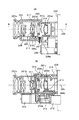
図8(A),(B)には、一般的な4群レンズ構成のズームレンズの鏡筒構造を示している。なお、(B)は(A)におけるA−A線断面を示している。
【0005】
このズームレンズを構成する4つのレンズ群201a〜201dは、固定された前玉レンズ201a、光軸に沿って移動することで変倍動作を行うバリエーターレンズ群201b、固定されたアフォーカルレンズ201c、および光軸に沿って移動することで変倍時の焦点面維持と焦点合わせを行うフォーカシングレンズ群201dからなる。
【0006】
ガイドバー203,204a,204bは光軸205と平行に配置され、移動するレンズ群の案内および回り止めを行う。DCモータ206はバリエーターレンズ群201bを移動させる駆動源となる。
【0007】
前玉レンズ201aは前玉鏡筒202に保持され、バリエーターレンズ群201bはV移動環211に保持されている。また、アフォーカルレンズ201cは中間枠215に、フォーカシングレンズ群201dはRR移動環214に保持されている。
【0008】
前玉鏡筒202は、後部鏡筒216に位置決め固定されており、両鏡筒202,216によってガイドバー203が位置決め支持されているとともに、ガイドスクリュウ軸208が回転可能に支持されている。このガイドスクリュウ軸208は、DCモータ206の出力軸206aの回転がギア列207を介して伝達されることにより回転駆動される。
【0009】
バリエーターレンズ群201bを保持するV移動環211は、押圧ばね209とこの押圧ばね209の力でガイドスクリュウ軸208に形成されたスクリュー溝208aに係合するボール210とを有しており、DCモータ206によってガイドスクリュー軸208が回転駆動されることにより、ガイドバー203にガイドおよび回転規制されながら光軸方向に進退移動する。
【0010】
後部鏡筒216とこの後部鏡筒216に位置決めされた中間枠215にはガイドバー204a,204bが嵌合支持されている。RR移動環214は、これらガイドバー204a,204bによってガイドおよび回転規制されながら光軸方向に進退可能である。
【0011】
また、中間枠215には、絞りユニット235(絞り駆動源224)が固定されている。
【0012】
フォーカシングレンズ群201dを保持するRR移動環214には、ガイドバー204a,204bにスライド可能に嵌合するスリーブ部が形成されており、またラック213が光軸方向についてRR移動環214と一体的となるように組み付けられている。
【0013】
ステッピングモータ212は、その出力軸に一体形成されたリードスクリュー212aを回転駆動する。リードスクリュー212aにはRR移動環214に組み付けられたラック213が係合しており、リードスクリュー212aが回転することによって、RR移動環214がガイドバー204a,204bによりガイドされながら光軸方向に移動する。
【0014】
なお、バリエーターレンズ群の駆動源としては、フォーカシングレンズ群の駆動源と同様にステッピングモータを用いてもよい。
【0015】
そして、前玉鏡筒202、中間枠215および後部鏡筒216により、レンズ等を略密閉収容するレンズ鏡筒本体が形成される。
【0016】
また、このようなステッピングモータを用いてレンズ群保持枠を移動させる場合には、フォトインタラプタ等を用いて保持枠が光軸方向の1つの基準位置に位置することを検出した後に、ステッピングモータに与える駆動パルスの数を連続的にカウントすることにより、保持枠の絶対位置を検出する。
【0017】
▲2▼ 次に、従来の撮像装置における電気的構成について、図9を用いて説明する。なお、この図において、図8にて説明したレンズ鏡筒の構成要素については、図8と同符号を付す。
【0018】
221はCCD等の固体撮像素子、222はバリエーターレンズ群201bの駆動源であり、モータ206(又はステッピングモータ)、ギア列207およびガイドスクリュー軸208等を含む。
【0019】
223はフォーカシングレンズ群201dの駆動源であり、ステッピングモータ212、リードスクリュー軸212aおよびラック213等を含む。
【0020】
224はバリエーターレンズ群201bとアフォーカルレンズ201cとの間に配置された絞りユニット235の駆動源である。
【0021】
225はズームエンコーダー、227はフォーカスエンコーダーである。これらのエンコーダーはそれぞれ、バリエーターレンズ群201bおよびフォーカシングレンズ群201dの光軸方向の絶対位置を検出する。なお、図8に示すようにバリエーター駆動源としてDCモータを用いる場合には、ボリューム等の絶対位置エンコーダーを用いたり、磁気式のものを用いたりする。
【0022】
また、駆動源としてステッピングモータを用いる場合には、前述したような基準位置に保持枠を配置してから、ステッピングモータに入力する動作パルス数を連続してカウントする方法を用いるのが一般的である。
【0023】
226は絞りエンコーダーであり、モータ等の絞り駆動源224の内部にホール素子を配置し、ローターとステーターの回転位置関係を検出する方式のものなどが用いられる。
【0024】
232は本カメラの制御を司るCPUである。228はカメラ信号処理回路であり、固体撮像素子221の出力に対して所定の増幅やガンマ補正などを施す。これらの所定の処理を受けた映像信号のコントラスト信号は、AEゲート229およびAFゲート230を通過する。即ち、露出決定およびピント合わせのために最適な信号の取り出し範囲が全画面内のうちこのゲートで設定される。このゲートの大きさは可変であったり、複数設けられたりする場合がある。
【0025】
231はAF(オートフォーカス)のためのAF信号を処理するAF信号処理回路であり、映像信号の高周波成分に関する1つもしくは複数の出力を生成する。233はズームスイッチ、234はズームトラッキングメモリである。ズームトラッキングメモリ234は、変倍に際して被写体距離とバリエーターレンズ位置に応じてセットすべきフォーカシングレンズ位置の情報を記憶する。なお、ズームトラッキングメモリとしてCPU232内のメモリを使用してもよい。
【0026】
例えば、撮影者によりズームスイッチ233が操作されると、CPU232は、ズームトラッキングメモリ234の情報をもとに算出したバリエーターレンズとフォーカシングレンズの所定の位置関係が保たれるように、ズームエンコーダー225の検出結果となる現在のバリエーターレンズの光軸方向の絶対位置と算出されたバリエーターレンズのセットすべき位置、およびフォーカスエンコーダー227の検出結果となる現在のフォーカスレンズの光軸方向の絶対位置と算出されたフォーカスレンズのセットすべき位置がそれぞれ一致するように、ズーム駆動源222とフォーカスシング駆動源223を駆動制御する。
【0027】
また、オートフォーカス動作ではAF信号処理回路231の出力がピークを示すように、CPU232は、フォーカシング駆動源223を駆動制御する。
【0028】
さらに、適正露出を得るために、CPU232は、AEゲート229を通過したY信号の出力の平均値を所定値として、絞りエンコーダー226の出力がこの所定値となるように絞り駆動源224を駆動制御して、開口径をコントロールする。
【0029】
▲3▼ 次に、TV信号AFについて説明する。ここでは、上述したオートフォーカス動作に関してより詳細に説明する。この方式は、オートフォーカシングを行うためのセンサとして、撮像装置の撮像素子そのものを兼用するために、他のAFセンサを設ける場合に比べて部品数が少なくなり、コスト的に有利である。また、直接、結像面の像の状態を検出しているので、例えば温度変化があって鏡筒部品に伸縮が起き、ピント位置が変化した場合でも、その変化に応じて正しいピント位置の検出が可能である。
【0030】
図10にその原理を示す。図10のグラフにおいて、横軸に焦点調節のためのレンズ群位置をとり、縦軸に撮像信号の高周波成分(焦点電圧)をとる。図中、矢印で示した位置Aで焦点電圧のピークを示しており、この位置Aがピントが合った状態のレンズ位置となる。
【0031】
ここで焦点電圧Fの求め方の一例を挙げる。図11(A)には、実際の撮像視野を示しており、720が画角、718が自動焦点調節を行うための映像信号を取り出す範囲、719は被写体像である。
【0032】
図11(B)において、(a)は映像信号を取り出す範囲内の被写体像の様子を示す。また、(b)は(a)で示した被写体像の映像信号(Y信号)である。
【0033】
この信号を微分すると、(c)のような波形となり、さらに絶対値化すると(d)となる。
【0034】
そして、これをサンプルホールドした信号(e)が焦点電圧となる。これは、被写体像の有するコントラスト信号のうち、特に高周波の成分が、ピントが合った状態で最大となることを利用しているもので、焦点電圧の作成方法としては上述以外にも種々の方法が知られている。
【0035】
また、高周波成分のみを取り出すためのハイパスフィルターを用いる場合が多いが、このフィルターの特性を何種類か有し、複数の周波数に対して焦点電圧を作成して、これら複数の情報を基に正しいピントを保証することも知られている。
【0036】
図12には、このような自動焦点調節装置とインナーフォーカスレンズとを組み合わせたカメラの構成を示している。
【0037】
805の結像位置にはCCD等の撮像素子が配置される。そして、この撮像素子を通じて輝度信号Yが作られ、所定枠718内の情報が焦点検出回路(AF回路)821に取り込まれる。
【0038】
AF回路821は、前述した方法等により焦点電圧を求め、この値と、フォーカシングレンズ804Bの駆動方向や駆動に伴う焦点電圧の変化の符号などを基に、合焦か非合焦か、非合焦の場合にはぼけがいわゆる前ピンか後ピンか等を判定し、この判定結果に基づいてフォーカスレンズ駆動用のモータ822を所定方向に駆動する。
【0039】
ここで述べたようなテレビ信号オートフォーカスと呼ばれる方式では、このように撮像装置のイメージャーであるセンサがオートフォーカスのセンサを兼用するので、ダイレクトに結像面の結像状態を測定でき、高精度に焦点の状況を把握できる。
【0040】
▲4▼ 次に、ズームトラッキングの方法について説明する。上述した▲2▼でも簡単に触れたが、このようなバリエーターよりも後方のレンズ群でフォーカシングを行う場合、被写体距離に応じてズーム中のフォーカシングレンズがたどるべき軌跡が異なる。
【0041】
このため、ズームスタートに際してのバリエーターレンズとフォーカシングレンズの両方の光軸方向の絶対位置を測定しておき、この情報から、ズームが行われた時に2つのレンズのとるべき位置関係を明確化して、その位置を守るような動作を行うことで、ズーム中もピントを維持することが可能となる。この動作をここではズームトラッキングと称する。
【0042】
この方法として、特開平1−321416号公報には、複数の被写体距離に対してワイド端からテレ端の間の複数のバリエーターレンズ位置に対するフォーカシングレンズ位置を記憶しておき、ズーム開始時に、その時点でのバリエーターレンズ位置とフォーカシングレンズ位置がマイコン内の記憶手段などに記憶されたマップ情報のどこにあるかを知り、その点のデータと、同じ焦点距離で前ピン側に最も近く記憶されたデータと、後ピン側に最も近く記憶されたデータとから内挿演算し、それぞれの焦点距離(バリエーター位置)でのフォーカシングレンズ位置を算出する方法が示されている。
【0043】
図13には、テレ端付近でのトラッキングカーブ(軌跡)の説明図を示している。この図において、横軸がバリエーターレンズ位置であり、Vnがテレ端位置である。また、縦軸はフォーカシングレンズ位置である。
【0044】
例えば無限距離に対して、P1,P4,P7、P10が記憶されているとともに、10mに対して、P2、P5,P8、P11が記憶されているものとする。この時、P点にある状態(テレ端で被写体距離が10mと無限の間のある距離の状態)からワイド方向にズームすると、バリエーターレンズとフォーカシングレンズの位置関係が、PからPA,PB,PCを順にたどるように制御される。
【0045】
このPA〜PCの位置は、上下の記憶された軌跡LL1とLL2との内挿比が一定となる位置である。
【0046】
▲5▼ 次に、交換レンズシステムについて説明する。従来、撮像装置に対して撮影レンズが交換可能なものが多用されている。
【0047】
図14には、交換可能なレンズを用いた撮影システムの一例を示している。この交換レンズ900は、前述と同様に、被写体側から凸凹凸凸の順の4群構成からなるズームレンズを使用している。ただし、これ以外の構成のレンズを用いてもよい。
【0048】
911は固定の前玉、912は光軸方向に移動することで変倍動作を行うバリエーターレンズ、936は絞り、913は固定のアフォーカルレンズ、914はフォーカシングレンズである。フォーカシングレンズ914は、被写体距離が変わった場合のフォーカシング動作とズーム中のコンペンセーターとしての働きを合わせ持っている。
【0049】
945、952、937はそれぞれ、バリエーター、絞り、フォーカシングレンズの駆動源であり、それぞれ駆動回路961,951,962を介してレンズマイクロコンピュータ910によって駆動制御される。
【0050】
カメラ1000側には、3つのCCD等の撮像素子1003〜1005が設けられており、それぞれから出力される信号はアンプ1005〜1007により増幅される。これら信号は信号処理回路1152に入力され、ここで所定レベルの映像信号が生成される。生成された映像信号は、本体マイコン1009に伝達される。
【0051】
2つのマイクロコンピュータ910,1009は接点318,307を介して接続される通信経路をもって結ばれている。これにより、各種の信号のやりとりが行われる。
【0052】
例えば、前述のテレビ信号オートフォーカスのための焦点電圧をカメラ1000側の信号処理回路1152の中で生成しているとすると、その情報は本体マイコン1009からレンズマイコン910に送信される。
【0053】
レンズマイコン910ではこの信号情報に基づいて合焦か非合焦かどうか(ボケの方向とその程度)を判定し、フォーカシングレンズをどちらにどれだけのスピードで駆動するかを定めて、駆動回路962を介してフォーカシング駆動源937を駆動する。
【0054】
▲6▼ 次に撮像素子について説明する。CCD撮像素子は、民生用ビデオカメラでは1/3インチ型、1/4インチ型と称される、対角寸法が6mm,4mm程度のものが主流となってきている。そして、この大きさの中に、例えば31万個の画素を有している。
【0055】
また、デジタルスチルカメラでは、1/2インチ型(対角寸法8mm)程度のCCDにて、200万個の画素を有するようなものも使われている。
【0056】
このような大画素数のCCDを用いたデジタルカメラにおいては、一般的な小型プリントサイズでは、条件がそろえば従来のフィルムカメラで撮影した写真と遜色のない画質が確保できるようになってきている。
【0057】
このようなビデオカメラにおいて、許容錯乱円径は12〜15μm程度、また、デジタルスチルカメラでは7〜8μm程度と、従来の135フィルムフォーマットの許容錯乱円33〜35μmと比較するとはるかに小さな数字となる。
【0058】
これは、画面対角寸法が、上述のように135フィルムフォーマットの43mmに比べるとはるかに小さいためである。また、この数字はCCDの画素サイズが更に小さくなると、更に小さな数字となると予想される。
【0059】
また、別の観点から考えると、CCDを用いる撮像装置では、同じ画角を得るための焦点距離が、135フィルムカメラに比べて、イメージサイズが小さい分、短くなる。
【0060】
例えば、135フィルムカメラで40mmの標準焦点距離で得られる画角は、1/4インチのCCDを用いた撮像装置では4mmとなる。このため、同じF値で撮影しているときの被写界深度は、フィルムカメラと比較すると、これらのCCDを用いた撮像装置ではきわめて深くなる。
【0061】
一方、焦点深度は、よく知られているように、許容錯乱円径×F値(絞り値)で求められるから、例えば、F2のとき、135フィルムカメラの焦点深度(片側)は0.035×2=0.07mmであるのに対し、1/2インチ型の撮像装置では0.007×2=0.014mmと狭くなる。
【0062】
上述のように対角寸法が同じCCD、例えば6mmの1/3インチ型のCCDにおいても、100万画素からさらに200万、将来的には300万と画素数を多くして解像感を上げることを目的としたものから、画素の大きさをむやみに小さくせずにダイナミックレンジや感度を重視したものなど、種々の仕様のものが知られている。
【0063】
▲7▼ 次に、光量調節方法について説明する。ビデオカメラやデジタルスチルカメラのようなCCD等の撮像素子をイメージセンサとして用いた撮像装置においては、CCDの輝度信号のレベルがある定まった範囲となるように、絞り装置により開口を制御して自動的に最適な露出を得る方法が一般的である。
【0064】
絞り装置としては、開口形状がひし形となる2枚の絞り羽根を用いたものや、5枚又は6枚の羽根を用いた虹彩絞りなどが知られている。
【0065】
ところで、絞り開口径が小さくなると回折により画質が劣化するという問題が発生する。このため、これらの撮像装置では、画質劣化が発生しない若しくは発生してもあまり大きな問題とならない範囲に絞り開口径の制御範囲を制限することが一般的に行われている。
【0066】
これは現在の絞り値をマイクロコンピュータが把握し、定められた所定のF値より小絞り側は使用しないようにするものである。
【0067】
しかし、使用できる絞り範囲にこのような制限をかけると、実際の被写界の有する広範囲な明るさに対して絞りだけで光量を最適に調節することが困難となる。
【0068】
このため、絞り羽根に一体的にNDフィルターを貼り付けて、絞り径が小さくなると絞り開口をNDフィルターが覆うように構成することで、同じ絞り制御(例えば、開放〜F8)で調節可能な明るさ範囲を広げることが行われている。また、CCDの電荷蓄積時間(シャッター速度)を可変とする方法が組み合わされる場合もある。
【0069】
なお、NDフィルターには、上述のように絞りの羽根に一体的に貼り付けられて駆動されるもの以外に、専用の駆動源を有し、絞りとは別に光路内への挿入量が制御されるものもある。
【0070】
▲8▼ 次に、撮影レンズについて説明する。撮影レンズは、使用されるCCDの画素ピッチから決まる必要な解像性能(MTF性能)が得られるように設計製造される。
【0071】
また、撮影レンズは、CCDのサイズによって決まる有効像円を有するものである。
【0072】
以上のように構成される撮像装置では、多くの機能がCCD仕様を基本としてこれに最適化されるように設計されている。
【0073】
まず、AFについては、CCDから得られる映像信号の高周波成分のピークを持って焦点を判断しているので、CCDの画素ピッチにより定まる許容錯乱円と絞りの開放F値により、フォーカスレンズをステッピングモータで駆動する場合の1ステップの移動量が設定される。
【0074】
また、レンズのいわゆるウォブリング(光軸方向への微小往復駆動)によってベストピントの方向を探る場合には、F値に応じたウォブリング量も許容錯乱円仕様(ひいてはCCD仕様)により定められるし、また、合焦か非合焦かの判定を行う際のレベルもCCDに関連して定まる。
【0075】
また、AEについては、CCDの画素ピッチによって、小絞り回折による像劣化の発生するF値が定まる。そして、このF値よりも小絞り側を使用しないように露出が制御される。
【0076】
有効像円については、レンズの設計製造に際してCCDのサイズに合わせて、けられが発生しないように設計される。解像性能については、レンズの設計製造に際してCCDの画素ピッチ仕様などから設計値が定まる。
【0077】
このように、レンズが交換可能な撮像装置においても、この撮像装置がどのような仕様のCCDを用いているかに応じて、全ての交換レンズに対して良好な撮像性能が得られるように設計される。
【0078】
【発明が解決しようとする課題】
しかしながら、CCDは、フィルムカメラで言えばフィルムそのものであり、撮影目的に応じて、前述したように低感度でも高画質を求めるのか、それとも高感度を求めるのかなど、同じイメージサイズでも仕様によって特性(例えば、画素数、感度、ダイナミックレンジ)が異なってくる。
【0079】
また、CCDは半導体製造技術の向上にしたがって、年々画素サイズの小型化が進んでおり、年々仕様が変化して選択幅が広がっている状況にある。
【0080】
そのような状況の中で、ひとつのCCDを想定した交換レンズ撮影システムを定めても、CCDの進化に伴い、すぐにシステム全体が陳腐化したり、最新のCCDに合わせてその度、新たにレンズを設計し直す必要が生じたりしてしまう。
【0081】
また、CCDの持っている最大の性能を常に満足するレンズを用意すると、そのサイズで最も高画素のCCDを想定しても十分なMTFが得られることが必要であるから、そこまでの画質を要求しないようなユーザーは過剰性能のレンズ(多くの場合、MTFを上げるとレンズが大きくなる)を用いることになる。
【0082】
そこで、本発明では、撮影レンズ装置の有している種々の性能に応じて撮像装置側で効率良く適正な画像を記録できるようにすることを目的としている。
【0083】
これにより、CCDの最高性能を満足するのに十分な性能をレンズが有していない場合にも、そのレンズに応じて得られる画像を記録できるようにしたので、レンズとカメラの組合わせの使用可能範囲が拡大し、マウント条件(メカニズムおよびフランジバック値)さえ合致していれば、効率よく破綻のない画像の撮影が可能となる。
【0084】
【課題を解決するための手段】
上記の目的を達成するために本願第1の発明は、撮影レンズ装置の交換が可能であり、撮像素子による撮影画像を電子データとして記録する撮像装置であって、装着された撮影レンズ装置から撮影レンズ装置の焦点距離およびF値のうち少なくとも一方に応じたMTF(Modulation Transfer Function:いわば解像性能ないしコントラストの再現率)特性データを受信し、撮像された画像を記録するためのデータサイズを、受信したMTF特性データにより示される画像精細度に対応したデータサイズに設定する制御手段を設けている。
【0085】
これにより、装着された撮影レンズ装置の解像性能に応じた最適な、すなわち無駄のないデータサイズ(ファイルサイズ)で画像を記録することが可能となり、効率的な画像記録を行うことが可能となる。
【0086】
例えば、通常のテレビフォーマットに応じたVGAと称する画質記録を目的とした撮影レンズ装置を装着した場合において、その撮像装置が300万画素の撮像素子を有していて、300万画素に応じたファイルサイズで画像を記録しても、この撮影レンズ装置は300万画素の撮像素子で得られるはずの最高解像性能を得られないのであるから、不必要に大きなファイルサイズを用いていることになり効率が悪い。そこで、このような場合には、その撮影レンズ装置の性能(例えば、形成される画像の精細度)に応じて記録ファイルサイズ(使用ファイルサイズ)を縮小し、十分かつ最小のファイルサイズを設定すればよい。
【0087】
なお、データサイズ又は画像精細度の使用者による選択が可能である場合において、使用者により選択されたデータサイズ又は画像精細度が、上記制御手段が上記受信したMTFに関連する情報を用いて設定したデータサイズ又はこのデータサイズに対応する画像精細度よりも大きいときに警告動作を行わせるようにして、効率が悪い撮影であることを使用者に知らせることができるようにしてもよい。
【0088】
また、制御手段が設定した(MTF関連情報により又は使用者により選択された)データサイズに関連する情報、例えばデータサイズや画像詳細度を、電子ファインダ等の表示手段に表示させるようにして、撮影記録される画像のデータサイズ等を使用者が確実に認識できるようにしてもよい。
【0089】
また、本願第2の発明では、撮影レンズ装置の交換が可能であり、撮像素子による画像撮影を行う撮像装置において、装着された撮影レンズ装置から、この撮影レンズ装置のMTFに関連する情報を受信し、この受信したMTFに関連する情報に基づいて、撮影レンズ装置内に設けられた光量調節手段の調節範囲を可変設定する制御手段を設けている。
【0090】
これにより、装着された撮影レンズ装置の解像性能に応じた最適な、例えば小絞り回折が発生しない範囲で撮影レンズ装置内の光量調節手段に光量を調節させ、高画質の画像を記録することが可能となる。
【0091】
具体的には、例えば、制御手段に、受信したMTFに関連する情報に基づいて光量調節手段によって調節可能な最大F値を設定させ、その情報を撮影レンズ装置に対して送信させるようにすればよい。
【0106】
【発明の実施の形態】
図1には、本発明の第1実施形態である撮像システムの主要部構成を示している。この撮像システムは、カメラ本体(撮像装置)とこのカメラ本体に対して交換可能な撮影レンズとから構成されている。
【0107】
まず、撮影レンズ側の構成について説明する。図1において、111〜114は撮影レンズを構成する4つのレンズ群を示す。本実施形態の撮影レンズは、被写体側から順に凸凹凸凸の4つのレンズ群を有するズームレンズである。但し、本発明の撮影レンズ装置としては、このレンズ群構成の撮影レンズに限られない。
【0108】
111は固定の前玉レンズ群、112は光軸方向にその位置を可変とすることで焦点距離を変える(ズームを行う)バリエーターレンズ群、113は固定のアフォーカルレンズ群、114はズーム中にピントの合う被写体距離を一定に保つコンペンセーターの働きとフォーカシングレンズの働きとを有するフォーカスコンペレンズである。
【0109】
136はこの撮影レンズの光路中に挿入された絞りユニット(光量調節手段)であり、駆動源としてのIGメータ413を作動させて絞り開口面積(開口径)を変化させることにより通過光量を調節するものである。
【0110】
145はバリエーターレンズ群112を駆動するためのズームモータで、本実施形態では、ステッピングモータが用いられている。このズームモータ145は、ズーム駆動回路161によって印加される所定のステップパルスに応じて所定角度ずつ回転する。
【0111】
なお、ズームモータ145の回転をバリエーターレンズ群112の移動に変換する機構に関しては、図8にて説明した構成等を用いればよい。
【0112】
また、このズームモータ145を駆動するためにモータに入力したステップ数を継続してカウントすることにより、レンズ群112の光軸方向の絶対位置をエンコードすることができる。このためには、カウントのスタートにあたって、常にレンズ群112を所定の位置に配置する必要があり、本実施形態では、レンズ群112が所定の初期位置に位置したことを検出するためのズームリセットスイッチ501を設けている。
【0113】
すなわち、レンズマイコン410内に設けられたズームカウンタ503にて、ズームリセットスイッチ501がオンになった初期位置から継続してズームモータ145に入力したパルスをカウントすることにより、バリエーターエンコーダーが構成される。
【0114】
また、フォーカスコンペレンズ群114は、本実施形態ではステッピングモータからなるフォーカスモータ137により駆動される。そして、バリエーターレンズ群112に対して設けられたものと同様のフォーカス駆動回路162,フォーカスリセットスイッチ502およびフォーカスカウンタ507を有する。
【0115】
レンズマイコン410は、それ以外に、記憶部506、制御部504、通信部508を有している。
【0116】
記憶部506には、ズームトラッキングを行うためのマップデータのほか、本撮影レンズのMTF特性データや有効像円データが記憶されている。また、制御部504は、小絞り限界F値を設定する設定部505を有している。
【0117】
次に、カメラ本体側の構成について説明する。221はCCDにより構成されるイメージセンサ(撮像素子:以下、CCDという)である。但し、本発明における撮像素子はCCDに限られない。
【0118】
CCD221はCCDドライブ回路513により駆動される。CCD221から得られた画素ごとの電荷蓄積による映像信号(撮影画像)は、A/D変換部509にてデジタル信号化された後、カメラ信号処理回路510にて所定の信号処理(増幅やガンマ補正など)が施される。この信号処理を施された映像信号は、AFゲート230で所定の中央付近だけを取り出され、AF信号処理回路231にてY信号の高周波成分に関する情報に加工された後にカメラマイコン409に送られる。
【0119】
また、Y信号の高周波成分に関する情報に加工された信号は、不図示のブロックを通過した後、映像信号が所定のレベルにあるかの露出判断を行うための信号に加工されてカメラマイコン409に取り込まれる。
【0120】
これらの映像信号の高周波成分に関する値や、映像信号のレベルに関する信号はマウントを介してレンズマイコン410とカメラマイコン409との間で通信される。これらの信号を受けたレンズマイコン410は、合焦状態または最適露出状態を得るために絞りユニット136やフォーカスレンズ群114を駆動する。
【0121】
511は画像処理回路であり、カメラ信号処理回路510で生成された映像信号に対して、さらに電子ズーム処理を施して画像切り出しサイズを変更したり、不図示の電子的手振れ補正のための画像切り出し位置を変更したりする。また、これら以外に、画像解像度を変換して画像記録のためのファイルサイズ(データサイズ)を変更したり、圧縮処理をして撮影画像(電子データ)のデータサイズを変換したりする。さらに、レンズの有する歪曲収差を補正する処理を行う場合もある。
【0122】
512は画像処理回路511の出力(電子データ)を記録媒体に記録する記録系である。記録媒体としては、カード、ディスク、テープなどが用いられる。
【0123】
カメラマイコン409には、レンズマイコン410と同等に、制御部517、通信部518および記憶部519が設けられている。記憶部519は、自己の有するCCDのサイズ(有効対角長)、画素数、画素ピッチに関する情報などが記憶されている。
【0124】
また、カメラ本体側が有する、ユーザーにより操作されるスイッチの状態はすべてカメラマイコン409に入力される。本実施形態では、トリガースイッチ513、ズームスイッチ514、記録精細度設定スイッチ515、動画/静止画モード切り換えスイッチ516などの状態が入力される。
【0125】
以上のように構成された、カメラ本体に対して撮影レンズを交換可能に構成した撮像システムにおいて、マウントに設けられた通信接点を介してレンズマイコン410とカメラマイコン409との間で通信が行われる際に、レンズ側のMTF特性に関連する情報(以下、MTF関連情報という)がカメラ本体側に送信される。
【0126】
なお、ここにいうMTF関連情報としては、生のMTF特性データでもよいし、MTF特性データ値をもとにいくつかのレベルに置き換えた情報であってもよい。さらに、その後の信号処理が行い易いような何らかの換算結果を送信してもよい。すなわち、MTFに関連する情報であればその形態を問わない。
【0127】
ここで、画像精細度に関しては、VGA,XGA,SXGA等の各種レベルがあるが、この撮影レンズがどの程度のMTFを有しているかによって、どのレベルの精細度に対応する画像データファイルに対して十分な解像力を満たせるのかが変化する。
【0128】
例えば、撮影レンズが像面上50本/mmの精細度に対して十分に解像できる(例えば、MTF50%以上)か否かによって、VGA記録した場合とXGA記録した場合とで明らかに差が生じる場合(レンズ性能がXGA以上)と、どちらで記録しても結局はVGA記録した場合と同等の精細度しか得られない場合(レンズ性能がVGAクラスしか前提としていない)があり得る。
【0129】
一方、記録される画像情報のファイルサイズは精細度が高いほど大規模になり、カメラ本体にセットされた記録媒体の容量を消費することとなるので、効率が悪い。
【0130】
そこで、本実施形態では、レンズマイコン410から送信されたMTF関連情報に基づいて、カメラマイコン409で最適な記録ファイルサイズを設定することにより、撮影レンズの性能に応じて必要かつ十分な記録を行うようにしている。
【0131】
カメラマイコン409は、撮影レンズからのMTF関連情報により示される画像精細度に対して最適なファイルサイズを指示して画像処理回路511にて必要かつ十分な(最小の)ファイルサイズの画像データを作成する。
【0132】
さらに、本実施形態では、カメラマイコン409は、撮影レンズからのMTF特性データに基づいて、撮影レンズにおいて小絞り回折の発生する使用限界F値(最大F値)を設定し、この情報を撮影レンズに送信する。
【0133】
具体的には、レンズマイコン410から送信されたMTF関連情報とカメラマイコン409に設定されたCCD画素ピッチに関する情報とから、小絞り回折が発生するF値を算出し、このF値又はこれよりも若干小さなF値を使用限界F値として設定する。
【0134】
例えば、撮影レンズが特定サイズの300万画素CCDを想定し、かつ300万画素CCDの限界F値がF5.6である設定となっていても、カメラ本体側が同じサイズの200万画素CCDを有する場合はF8まで使用できるというときには、撮影レンズ側の小絞り限界F値の設定部505における設定を基準のF5.6からF8に置き換える。これにより、より広い範囲の露出調整が可能となる。
【0135】
また、本実施形態では、カメラマイコン409は、カメラ本体側で設定されたファイルサイズ又は画像精細度に関する情報を、電子ファインダ(LCDファインダや電子ビューファインダ)により構成されるファインダ表示部232に表示することにより、撮影者にその情報を伝達する。
【0136】
ここで、本実施形態のカメラ本体には、使用する画像精細度を記録精細度設定スイッチ515を通じて撮影者が任意設定することが可能である。この場合において、撮影者が撮影レンズの性能に対してミスマッチな(過度の)高画質記録に相当する画像精細度を設定した場合には、ファインダ表示部232に警告表示を行う。この警告動作に関しては、後述する図2のフローチャートにより判断・実行される。
【0137】
また、本実施形態の撮影レンズの記憶部506には、焦点距離およびF値の少なくとも一方に応じたMTF特性データが記憶されている。これにより、焦点距離やF値によらない代表的なMTF特性データを用いる場合に比べて、カメラ本体側においてより最適なファイルサイズや使用限界F値の設定を行うことができ、より効率的な画像記録を行うことができる。
【0138】
これは、通常、MTF特性データは焦点距離やF値によって異なり、ある条件ではCCDの性能をフルに引き出せないようなMTFの状況になっていても、別の条件では満足できる場合もある。したがって、焦点距離やF値を加味したMTF特性データをレンズマイコン410内(記憶部506)に有し、そのときの焦点距離とF値の状況に応じてMTF特性データに関連する情報をカメラマイコン409に伝達することで、カメラ本体側において効率的に必要かつ十分な範囲で最高画質の画像を記録できる。
【0139】
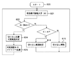
次に、図2のフローチャートを用いてカメラマイコン409の動作を説明する。まず、ステップ601でスタートすると、ステップ602でレンズマイコン410に対してMTF関連情報の送信要求を送信し、これに応答してレンズマイコン410から送信されてくるMTF関連情報を入手する。
【0140】
このとき送信されてくるMTF関連情報は、撮影レンズのその時点での焦点距離およびF値に応じたMTF特性データに基づくものである。
【0141】
ステップ603ではこの入手したレンズ側のMTF関連情報に基づいて、前述したように最適な記録ファイルサイズVaを定める。
【0142】
そして、ステップ604では、カメラ本体側の記録精細度設定がオートモードになっているかどうかを判定する。オートモードであるときは、ステップ603で定められた記録ファイルサイズVaが使用されることになり、撮影レンズの性能を最大に引き出すことができ、しかも不必要に大きなファイルサイズを用いない最適設定となる。この場合、ステップ605において使用ファイルサイズVをVaに設定する。
【0143】
使用ファイルサイズVが設定されると、撮影者がトリガースイッチ513を操作して記録動作のトリガーをかけた場合に、そのファイルサイズVの精細度で画像記録が行われる。
【0144】
一方、ステップ604でオートモードではない(マニュアルモードである)と判定したときは、ステップ606にて撮影者が設定したファイルサイズVmを読み込む。マニュアルモードの場合は、撮影者の設定値を優先するので、ステップ607にて使用ファイルサイズVをVmに設定する。
【0145】
次に、ステップ608では、カメラマイコン409がMTF関連情報に基づいて設定したファイルサイズVaと撮影者が設定したファイルサイズVmの大小比較を行う。Vaの方が大きい場合には、撮影者が設定したファイルサイズはレンズ性能から見て十分な精細度に対応するので、そのままステップ602に戻る。
【0146】
一方、撮影者が設定したファイルサイズVmが、レンズ性能上、そこまで高精細度の設定をしても、それ以下の設定(高精細度の画像精細度以下)で記録した画質と差がないと判断した場合、すなわち、Va<Vmとなっている場合には、ステップ609にてファインダ表示部232にその旨の警告表示を行う。
【0147】
撮影者はこの警告表示を見ることで、無駄に記録媒体の容量を消費する設定をしていることに気付き、マニュアル設定した記録精細度を落とす等して使用データサイズを最適設定に近付けることができる。
【0148】
なお、本実施形態では、撮影者が記録する画像の精細度をマニュアル設定できるようにしたが、ファイルサイズをマニュアル設定できるようにしてもよい。
【0149】
また、本実施形態では、図2のフローチャートにおいて、カメラマイコン409がMTF関連情報に基づいて設定したファイルサイズVaと撮影者が設定したファイルサイズVmとを比較する場合について説明したが、ファイルサイズVaに対応する画像精細度と撮影者が設定した画像精細度とを比較するようにしてもよい。
【0150】
(第2実施形態)
上記第1実施形態では、撮影レンズ側の有するMTF特性データをベースとするMTF関連情報をカメラ本体側に送信し、カメラ本体側ではこの情報に基づいてレンズ性能が最高に引き出せる範囲で最小のファイルサイズで記録が行えるようにしたが、本実施形態では、MTF関連情報ではなく、撮影レンズの有効像円に関連する情報(以下、有効像円関連情報という)をレンズ側からカメラ本体側へ送信する。
【0151】
本実施形態では、図1に示したレンズマイコン410の記憶部506に、この撮影レンズの有する有効像円径のデータが記憶されている。また、このデータは、撮影レンズの焦点距離やF値に応じた有効像円径の値として記憶されている。
【0152】
レンズマイコン410は、マウントを介してカメラマイコン409にこの有効像円関連情報を送信する。この送信される有効像円関連情報は、第1実施形態のMTF関連情報と同様に、生の有効像円データでもよいし、これを適宜変換した情報であってもよい。
【0153】
ここで、例えば、カメラ本体が有するCCD221の有効対角長が6mmであったとすると、これに有効像円径6mm以上の撮影レンズが装着されていれば、CCDから得られる全画面を記録しても無駄なくかつけられのない画像を撮影できる。
【0154】
しかし、有効像円径4mmの撮影レンズが装着されると、画面の隅がけられる(黒くなって画像のない状態となる)。したがって、このような場合は、カメラマイコン409では、レンズマイコン410から送信されてきた撮影レンズの有効像円関連情報に基づいて、けられのない画像が切り出せる範囲(CCD221上での画像取得範囲)を定め、画像処理回路511にてその切り出し範囲を設定することにより、無駄のない画像記録を行うことができる。
【0155】
また、本実施形態では、画像処理回路511にて設定された切り出し範囲で撮像した画像を、ファインダ表示部232に表示して、記録画角とほぼ同じ画角を示すとともに、撮影者に画角に関する情報を知らせる。
【0156】
例えば、有効像円径が4mmで設計された撮影レンズを対角長6mmのCCDを有するカメラ本体に装着しても、CCD上における対角長4mmの範囲のみを切り出すことになる。このため、同じ焦点距離(例えばf=5mm)を持っていても、それが6mmの有効像円径を有する撮影レンズを用いて画像の切り出しが必要ない場合と、4mmの有効像円径しかないために画像切り出しが必要な場合とでは画角に差が生じる。
【0157】
例えば、その画角を、135フィルムフォーマットされた撮影レンズの焦点距離に換算すると、同じf=5mmでも、有効像円径が6mmであれば約43mmとなり、有効像円径4mmで画像切り出すと約55mmとなる。
【0158】
本実施形態では、このように、多くのユーザーにとってなじみの深い135フィルムフォーマットの焦点距離に統一して画角を示すことにより、様々な有効像円径を有するレンズが装着されても、けられなく撮影できる画角を算出し、表示することでユーザーの混乱を避けるようにしている。
【0159】
このためには、カメラマイコン409内で、撮影レンズから送信されてきた有効像円関連情報により示される有効像円径Aと、同様にレンズ側から送信された撮影レンズの焦点距離の情報fと、カメラ本体自身の有するCCD221の対角長の情報Cとに基づいて、簡単な演算を行えばよい。
【0160】
すなわち、A<Cの場合、およそf×43/Aで、またC<Aの場合にはおよそf×43/Cで、そのときの画角が135フィルムフォーマットの焦点距離に換算される。ここで、「43」は135フィルムの対角長である。
【0161】
そして、この演算結果はカメラマイコン409によりファインダ表示部232に示される。
【0162】
次に、図3のフローチャートを用いて本実施形態におけるカメラマイコン409の動作を説明する。
【0163】
まず、ステップ611でスタートすると、ステップ612でレンズ側から接点を通した通信などで、レンズの有する有効像円情報Aを入手する。
【0164】
ステップ613では、この有効像円情報(有効像円径)Aとカメラ側のCCD221の有効対角長Cの値とを比較する。この比較の結果、CCD221の有効対角長Cの方が大きい場合(そのレンズではけられてしまう)には、けられない切り出し範囲をステップ614で設定する。
【0165】
また、レンズ側の有する有効像円がCCDをカバーしている場合(有効像円径Aが有効対角長Cよりも大きい場合)には、ステップ615にて、切り出し設定を解除する(解除してある場合はそのままとする)。
【0166】
なお、電子式手ぶれ補正がONされている場合は、標準的な切り出し範囲に設定してもよい。
【0167】
(第3実施形態)
図4には、本発明の第3実施形態である撮像システムの構成を示している。なお、本実施形態の撮像システムにおいて、第1実施形態の撮像システムと共通する構成要素には第1実施形態と同符号を付して説明に代える。
【0168】
本実施形態では、カメラ本体側に振れセンサ530が設けられており、この振れセンサ530から出力されるカメラ本体の振れに応じた信号が、カメラマイコン409に取り込まれるようになっている。
【0169】
なお、振れセンサ530としては、圧電振動ジャイロなどが用いられ、本実施形態では、縦(ピッチ)方向の回転成分検出用と、横(ヨー)方向の回転成分検出用の2個の振れセンサを設けている。
【0170】
従来の電子式振れ補正では、振れセンサから得られたカメラ本体の手振れ等による回転量と、そのときの焦点距離およびCCDのサイズに基づいて、CCDの全有効画面の中から画像として切り出すべき範囲の位置を定めていく(移動させていく)ことにより、連続した画像間での被写体の位置合わせを行い、像振れを補正していた。
【0171】
また、この際、CCDの大きさが十分大きければ問題ないが、CCDの大きさには制限があるので、あまり大きな振れ角度に対しては、100%の補正は行えず、むしろ動画が違和感を発生しないように、画像の切り出し限界位置付近ではソフトウェア的に切り出し方に工夫を加え、自然な画像となるようにしている。
【0172】
本実施形態では、このような電子式振れ補正機能を、レンズ交換が可能なカメラ本体が有する場合に、撮影レンズの有する有効像円が様々である場合でも、画像にけられが生じないようにするために、撮影レンズ側から送信される有効像円関連情報を利用して、電子的振れ補正により補正可能な範囲(つまりは、画像の切り出し範囲を移動させることが可能な範囲:移動許容範囲)および上記ソフト的補正のかかる位置などを最適化するものである。
【0173】
特に、撮影レンズの有する有効像円が焦点距離やF値などにより変化する場合には、それらの条件も含めて撮影レンズ側から送られてきた情報により、電子的振れ補正動作を行う。
【0174】
図5には、撮影レンズの焦点距離と電子的振れ補正により補正可能な振れ角度との関係を示している。図5の横軸は撮影レンズの焦点距離であり、縦軸は電子的振れ補正により補正できる振れ角度を示している。
【0175】
電子的振れ補正において、CCD上における画像切り出し範囲の移動可能量が一定であるとして角度換算すると、ワイド側ほど大きな振れ角度が、テレ側ほど小さな振れ角度が補正可能な最大振れ角度となる。
【0176】
ここで、図中の一点鎖線は、CCDの有効サイズに対してどの焦点距離でも撮影レンズの有効像円が大きく確保できている場合(そのようなカメラ本体と撮影レンズが組み合わさっている場合)での焦点距離に応じた補正可能な振れ角度を示している。
【0177】
一方、図中の実線は、焦点距離がワイドからミドルの範囲(W〜A点の焦点距離)では有効像円がCCDにおける切り出し画角を下回ることはないものの、CCDの全有効画面よりも小さくなり、A点の焦点距離からテレ側ではCCDの有効サイズより撮影レンズの有効像円の方が大きくなるようなカメラ本体と撮影レンズとが組み合わさっている場合での、焦点距離に応じた補正可能な振れ角度を示している。
【0178】
この場合、焦点距離によって補正可能な最大振れ角度が異なる(CCD上における画像切り出し範囲の移動可能量を一定にすると画像にけられが生じる)ので、カメラマイコン409は、画像切り出し範囲がそのときの焦点距離に応じた補正可能な最大振れ角度に対応する範囲内でのみ移動するように、画像切り出し範囲の移動を制限する。
【0179】
このように撮影レンズから送信されてきた有効像円関連情報から、焦点距離に応じた画像切り出し範囲の移動許容範囲を定め、この移動許容範囲の中で振れセンサからの出力に基づき、かつ動画に違和感の生じないような考慮を行って画像切り出し範囲の位置を決定することにより、そのときの焦点距離に応じた最大の補正可能振れ角度を確保しながら、画像のけられの生じない電子的振れ補正機能を実現することができる。
【0180】
なお、実線に示す特性では、ワイドから少しテレ側の焦点距離で補正可能角度が最小となるが、これは光学設計にもよるので、あくまで例に過ぎない。
【0181】
また、図5において、2点鎖線は、点Bよりワイド側では電子的振れ補正は機能できないような撮影レンズとカメラ本体との組み合わせを示している。点Bよりワイド側は、有効像円が画像切り出しサイズぎりぎりか、場合によっては切り出しサイズを撮影レンズの有効像円に合わせて縮小しなければならない領域である。
【0182】
また、点B〜点Cまでは、有効像円が切り出し範囲よりは大きくなっているが、CCDの全画面はカバーできていない。したがって、振れ補正は機能するが、十分な広い振れ角度に対する補正はできない場合がある。
【0183】
さらに、点Cからテレ端までの間は、CCDの全画面より大きな有効像円をレンズが有している。したがって、この範囲で振れ補正を行うことになる。
【0184】
このように、撮影レンズの有している有効像円関連情報に基づいて、電子的振れ補正機能を駆動したり駆動を制限(移動許容範囲を零とする)したりすることにより、振れ補正が可能な焦点距離領域での最大の補正可能振れ角度を確保しながら、画像のけられの生じない電子的振れ補正機能を実現することができる。
【0185】
次に、図6のフローチャートを用いて本実施形態におけるレンズマイコン410の動作を、また図7のフローチャートを用いて同じく本実施形態のカメラマイコン409の動作を説明する。
【0186】
図6において、ステップ616でスタートすると、ステップ617でそのときに設定されている焦点距離fの値を検出し、次にステップ618で、そのfの値での有効像円を決定する。これは、図5に示したような関係を記憶させたテーブルをマイコン内に設け、このテーブルから読み出すなどの方法となる。
【0187】
そして、ステップ619で、この決定した有効像円情報をカメラマイコンへ通信する。
【0188】
また、図7において、ステップ620でスタートすると、ステップ621でレンズ側より、上記図6のフローチャートのステップ619にて通信された有効像円Aの情報を受け取る。
【0189】
ステップ622では、手ぶれ補正(IS)がONであるかどうかを判断し、OFFの場合は、図3におけるステップ613への移行と同等となり、図3のステップ614,615と同じ処理を行う。
【0190】
ISがONの場合にはステップ624にて切り出し位置が、CCD221の有効画面の中心から上下左右にどれくらい移動できるかを、例えば走査線本数や画素列数などで決定する。そして、けられないで動かせる範囲を、有効像円情報Aから決める。この際、有効像円情報AとCCD対角長情報Cの値を用いることになる。
【0191】
そして、どのくらい切り出し位置を可変できるかの値をステップ625で手ぶれ補正機能を制御しているISマイコンなどに通信する。ISマイコン側はこの値をもとに、前述したような動画に違和感の生じないような制御を行う。
【0192】
【発明の効果】
以上説明したように、本願第1および第3の発明によれば、撮像された画像を記録するためのデータサイズを、撮影レンズ装置から受信したMTFに関連する情報に対応したデータサイズに設定するので、装着された撮影レンズ装置の解像性能に応じた最適な、すなわち無駄のない使用データサイズ(ファイルサイズ)で画像を記録することができ、効率的な画像記録を行うことができる。
【0193】
なお、データサイズ又は画像精細度の使用者による選択が可能である場合において、使用者により選択されたデータサイズ(又は画像精細度)が、上記制御手段が上記受信したMTFに関連する情報を用いて設定したデータサイズ(又はこのデータサイズに対応した画像精細度)よりも大きいときに警告動作を行わせるようにすれば、効率が悪い撮影であることを使用者に確実に知らせることができる。
【0194】
また、本願第2および第4の発明によれば、撮影レンズ装置から受信したMTFに関連する情報(指令)に基づいて、撮影レンズ装置内に設けられた光量調節手段の調節範囲(指令)を可変設定するようにしているので、装着された撮影レンズ装置の解像性能に応じた最適な、例えば小絞り回折が発生しない範囲で撮影レンズ装置内の光量調節手段に光量を調節させ、高画質の画像を記録することができる。
【0195】
なお、上記第1から第4の発明において、撮影レンズ装置から受信するMTF関連情報を、この撮影レンズ装置の焦点距離およびF値のうち少なくとも一方に応じた情報とすれば、より効率的な撮影を行うことができる。
【0196】
また、本願第5および第7の発明によれば、撮影レンズ装置から受信した有効像円に関連する情報に基づいて、撮像素子上での画像取得範囲の大きさを可変設定するようにしているので、装着された撮影レンズ装置の有効像円に応じた最適な、すなわち無駄のないかつ画像がけられない大きさの画像取得範囲で画像を記録することができ、効率的でけられのない画像記録を行うことができる。
【0197】
また、本願第6および第7の発明によれば、撮影レンズ装置から受信した有効像円に関連する情報に基づいて、電子的像振れ補正のために撮像素子上において画像取得範囲を移動させることが可能な移動許容範囲を可変設定するので、装着された撮影レンズ装置の有効像円に応じた最適な、すなわち無駄のないかつ画像がけられない最大の移動許容範囲を設定することができ、けられがなく効果的な振れ補正を行うことができる。
【0198】
なお、撮影レンズ装置から受信する有効像円に関連する情報を、この撮影レンズ装置の焦点距離およびF値のうち少なくとも一方に応じた有効像円に関連する情報とすれば、より有効な像振れ補正を行うことができる。
【図面の簡単な説明】
【図1】本発明の第1実施形態である撮像システムの構成を示すブロック図である。
【図2】上記第1実施形態の撮像システムを構成するカメラ本体の動作フローチャートである。
【図3】本発明の第2実施形態である撮影システムの動作を示すフローチャートである。
【図4】本発明の第3実施形態である撮像システムの構成を示すブロック図である。
【図5】上記第3実施形態における補正可能角度と焦点距離との関係を示すグラフ図である。
【図6】本発明の第3実施形態である撮影システムの動作を示すフローチャートである。
【図7】本発明の第3実施形態である撮影システムの動作を示すフローチャートである。
【図8】従来のビデオカメラに用いる撮影レンズの断面図である。
【図9】従来の撮像システムの構成を示すブロック図である。
【図10】従来のテレビ信号を用いた自動焦点調節の原理を説明するための図である。
【図11】従来のテレビ信号を用いた自動焦点調節の原理を説明するための図である。
【図12】従来のテレビ信号を用いた自動焦点調節の原理を説明するための図である。
【図13】従来のズームトラッキングのマップデータの一例を説明するための図である。
【図14】従来の交換レンズ式撮像システムの構成を示すブロック図である。
【符号の説明】
111〜114 レンズ群
221 CCD
409 カメラマイコン
410 レンズマイコン
506 記憶部
511 画像処理回路部
512 画像記録系
515 記録精細度設定スイッチ[0001]
BACKGROUND OF THE INVENTION
The present invention relates to an imaging apparatus such as a video camera, and more particularly to an imaging apparatus in which a photographic lens apparatus is replaceable.
[0002]
[Prior art]
(1) First, a zoom lens conventionally used in a video camera will be described.
[0003]
As a zoom lens for a video camera, for example, there is a zoom lens composed of four lens groups of a fixed convex, a movable concave, a fixed convex, and a movable convex in order from the subject side.
[0004]
8A and 8B show a lens barrel structure of a zoom lens having a general four-group lens configuration. In addition, (B) has shown the AA sectional view in (A).
[0005]
The four
[0006]
[0007]
The
[0008]
The
[0009]
The
[0010]
[0011]
An aperture unit 235 (aperture drive source 224) is fixed to the
[0012]
The
[0013]
The stepping
[0014]
Note that a stepping motor may be used as a driving source for the variator lens group, similarly to the driving source for the focusing lens group.
[0015]
The
[0016]
Further, when moving the lens group holding frame using such a stepping motor, after detecting that the holding frame is positioned at one reference position in the optical axis direction using a photo interrupter or the like, the stepping motor The absolute position of the holding frame is detected by continuously counting the number of applied driving pulses.
[0017]
(2) Next, the electrical configuration of the conventional imaging apparatus will be described with reference to FIG. In this figure, the same reference numerals as those in FIG. 8 are used for the components of the lens barrel described in FIG.
[0018]
[0019]
A
[0020]
[0021]
225 is a zoom encoder and 227 is a focus encoder. Each of these encoders detects the absolute position of the
[0022]
When a stepping motor is used as a drive source, it is common to use a method in which the holding frame is arranged at the reference position as described above and then the number of operation pulses input to the stepping motor is continuously counted. is there.
[0023]
[0024]
A
[0025]
[0026]
For example, when the
[0027]
In the autofocus operation, the
[0028]
Further, in order to obtain an appropriate exposure, the
[0029]
(3) Next, the TV signal AF will be described. Here, the above-described autofocus operation will be described in more detail. This method is advantageous in terms of cost because the number of components is reduced as compared with the case where other AF sensors are provided because the image pickup device itself of the image pickup apparatus is also used as a sensor for performing autofocusing. In addition, since the state of the image on the imaging plane is directly detected, even when the lens part expands or contracts due to a temperature change and the focus position changes, the correct focus position is detected according to the change. Is possible.
[0030]
FIG. 10 shows the principle. In the graph of FIG. 10, the horizontal axis represents the lens group position for focus adjustment, and the vertical axis represents the high-frequency component (focus voltage) of the imaging signal. In the figure, the peak of the focus voltage is shown at position A indicated by the arrow. , This position A is the lens position in focus.
[0031]
Here, an example of how to obtain the focal voltage F is given. FIG. 11A shows an actual imaging field of view, where 720 is an angle of view, 718 is a range in which a video signal for performing automatic focus adjustment is extracted, and 719 is a subject image.
[0032]
In FIG. 11B, (a) shows the state of the subject image within the range from which the video signal is extracted. Further, (b) is a video signal (Y signal) of the subject image shown in (a).
[0033]
When this signal is differentiated, it becomes a waveform as shown in (c), and further converted into an absolute value (d).
[0034]
A signal (e) obtained by sampling and holding this becomes a focus voltage. This uses the fact that the high-frequency component of the contrast signal of the subject image is maximized in a focused state, and various methods other than the above can be used as a method of creating the focus voltage. It has been known.
[0035]
In many cases, a high-pass filter for extracting only high-frequency components is used. However, this filter has several types of characteristics, and a focus voltage is created for a plurality of frequencies, and correct based on the plurality of information. It is also known to guarantee focus.
[0036]
FIG. 12 shows a configuration of a camera in which such an automatic focus adjustment device and an inner focus lens are combined.
[0037]
An imaging element such as a CCD is disposed at the
[0038]
The
[0039]
In the method called the TV signal autofocus as described here, the imager of the imaging apparatus also serves as the autofocus sensor in this way, so that the imaging state of the imaging surface can be measured directly, and high You can grasp the focus on accuracy.
[0040]
(4) Next, a zoom tracking method will be described. As mentioned above in (2), when focusing is performed with a lens group behind such a variator, the trajectory to be followed by the focusing lens during zooming differs depending on the subject distance.
[0041]
For this reason, the absolute positions in the optical axis direction of both the variator lens and the focusing lens at the start of zooming are measured, and from this information, the positional relationship between the two lenses when zooming is clarified, By performing an operation that protects the position, the focus can be maintained even during zooming. This operation is referred to herein as zoom tracking.
[0042]
As this method, Japanese Laid-Open Patent Publication No. 1-321416 stores focusing lens positions with respect to a plurality of variator lens positions between a wide end and a tele end with respect to a plurality of object distances, and at the time of zoom start, To know where the variator lens position and the focusing lens position in the map information stored in the storage means in the microcomputer are, and the data of that point and the data stored closest to the front pin side at the same focal length The method of interpolating from the data stored closest to the rear pin side and calculating the focusing lens position at each focal length (variator position) is shown.
[0043]
FIG. 13 shows an explanatory diagram of a tracking curve (trajectory) near the tele end. In this figure, the horizontal axis is the variator lens position, and Vn is the tele end position. The vertical axis represents the focusing lens position.
[0044]
For example, P1, P4, P7, and P10 are stored for an infinite distance and P2, P5, P8, and P11 are stored for 10 m. At this time, when zooming in the wide direction from the state at the P point (a state where the object distance is 10 m and infinity at the tele end), the positional relationship between the variator lens and the focusing lens changes from P to PA, PB, PC. Are controlled in order.
[0045]
The positions of PA to PC are positions where the interpolation ratio between the upper and lower stored loci LL1 and LL2 is constant.
[0046]
(5) Next, the interchangeable lens system will be described. 2. Description of the Related Art Conventionally, an imaging device that can exchange a photographic lens has been widely used.
[0047]
FIG. 14 shows an example of an imaging system using interchangeable lenses. As described above, the
[0048]
[0049]
[0050]
Three
[0051]
The two
[0052]
For example, if the focus voltage for the above-described television signal autofocus is generated in the
[0053]
Based on this signal information, the
[0054]
(6) Next, the image sensor will be described. CCD image sensors, which are called 1/3 inch type and 1/4 inch type in consumer video cameras, have diagonal dimensions of about 6 mm and 4 mm. For example, 310,000 pixels are included in this size.
[0055]
In the digital still camera, a CCD having a size of about 1/2 inch (diagonal dimension: 8 mm) having 2 million pixels is used.
[0056]
In such a digital camera using a CCD having a large number of pixels, an image quality comparable to that of a photograph taken with a conventional film camera can be secured with a general small print size if conditions are met. .
[0057]
In such a video camera, the permissible circle of confusion is about 12 to 15 μm, and the digital still camera is about 7 to 8 μm, which is much smaller than the permissible circle of confusion 33 to 35 μm of the conventional 135 film format. .
[0058]
This is because the screen diagonal dimension is much smaller than 43 mm of the 135 film format as described above. This number is expected to become a smaller number when the pixel size of the CCD is further reduced.
[0059]
Considering from another viewpoint, in an imaging apparatus using a CCD, the focal length for obtaining the same angle of view becomes shorter as the image size is smaller than that of a 135 film camera.
[0060]
For example, the angle of view obtained with a standard focal length of 40 mm with a 135 film camera is 4 mm with an imaging device using a 1/4 inch CCD. For this reason, the depth of field when photographing with the same F value is extremely deep in an imaging device using these CCDs as compared with a film camera.
[0061]
On the other hand, as is well known, the depth of focus is obtained by allowable confusion circle diameter × F value (aperture value). For example, at F2, the depth of focus (one side) of a 135 film camera is 0.035 ×. In contrast to 2 = 0.07 mm, a 1 / 2-inch imaging device has a narrowness of 0.007 × 2 = 0.014 mm.
[0062]
As described above, even with a CCD having the same diagonal dimension, for example, a 1/3 inch type CCD of 6 mm, the resolution is improved by increasing the number of pixels from 1 million to 2 million, and in the future, 3 million. In order to achieve this, various types of specifications are known, such as those that emphasize the dynamic range and sensitivity without unnecessarily reducing the size of the pixels.
[0063]
(7) Next, a light amount adjustment method will be described. In an imaging device using an image sensor such as a CCD as an image sensor, such as a video camera or a digital still camera, the aperture is controlled automatically by a diaphragm so that the level of the luminance signal of the CCD is within a predetermined range. In general, a method for obtaining optimal exposure is generally used.
[0064]
Known diaphragm devices include those using two diaphragm blades having a diamond-shaped opening, and iris diaphragms using five or six blades.
[0065]
By the way, when the aperture diameter becomes small, there arises a problem that the image quality deteriorates due to diffraction. For this reason, in these image pickup apparatuses, it is a general practice to limit the aperture opening diameter control range to a range in which image quality deterioration does not occur or does not cause a significant problem.
[0066]
This is because the microcomputer grasps the current aperture value and does not use the aperture on the side smaller than the predetermined F value.
[0067]
However, if such a restriction is applied to the usable aperture range, it becomes difficult to optimally adjust the light amount with only the aperture for a wide range of brightness of the actual field.
[0068]
For this reason, an ND filter is integrally attached to the aperture blades, and the aperture opening is covered by the ND filter when the aperture diameter is reduced, so that the brightness can be adjusted with the same aperture control (for example, open to F8). The range is being expanded. In some cases, a method of making the charge accumulation time (shutter speed) of the CCD variable is combined.
[0069]
The ND filter has a dedicated drive source in addition to the one that is integrally attached to the diaphragm blades and driven as described above, and the amount of insertion into the optical path is controlled separately from the diaphragm. Some are.
[0070]
(8) Next, the photographing lens will be described. The photographic lens is designed and manufactured so as to obtain the necessary resolution performance (MTF performance) determined by the pixel pitch of the CCD used.
[0071]
The photographing lens has an effective image circle determined by the size of the CCD.
[0072]
The imaging apparatus configured as described above is designed so that many functions are optimized based on the CCD specifications.
[0073]
First, with respect to AF, since the focus is determined with the peak of the high frequency component of the video signal obtained from the CCD, the focus lens is set to the stepping motor based on the permissible circle of confusion determined by the pixel pitch of the CCD and the open F value of the aperture. The amount of movement in one step when driving with is set.
[0074]
In addition, when searching for the best focus direction by so-called wobbling of the lens (micro reciprocating drive in the optical axis direction), the wobbling amount corresponding to the F value is also determined by the permissible circle of confusion (and CCD specification), and The level for determining whether the focus is in focus or not is also determined in relation to the CCD.
[0075]
For AE, the F value at which image degradation occurs due to small aperture diffraction is determined by the pixel pitch of the CCD. The exposure is controlled so as not to use the smaller aperture side than the F value.
[0076]
The effective image circle is designed so as not to be distorted according to the size of the CCD when designing and manufacturing the lens. . As for the resolution performance, the design value is determined from the pixel pitch specification of the CCD at the time of designing and manufacturing the lens.
[0077]
In this way, even in an imaging device with interchangeable lenses, it is designed so that good imaging performance can be obtained for all interchangeable lenses, depending on the specifications of the CCD used by the imaging device. The
[0078]
[Problems to be solved by the invention]
However, a CCD is a film itself in the case of a film camera. Depending on the purpose of shooting, as described above, whether a high image quality is required even at low sensitivity or whether high sensitivity is required, the characteristics ( For example, the number of pixels, sensitivity, and dynamic range are different.
[0079]
In addition, with the improvement of semiconductor manufacturing technology, the size of a pixel has been reduced year by year as the CCD has been improved.
[0080]
Under such circumstances, even if an interchangeable lens imaging system that assumes a single CCD is determined, the entire system will soon become obsolete with the evolution of the CCD, or a new lens will be added each time the latest CCD is used. May need to be redesigned.
[0081]
Also, if a lens that always satisfies the maximum performance of a CCD is prepared, it is necessary to obtain a sufficient MTF even if the CCD with the highest pixel size is assumed. Users who do not require use lenses with excessive performance (in many cases, increasing the MTF increases the size of the lens).
[0082]
In view of the above, an object of the present invention is to enable a proper image to be efficiently recorded on the imaging device side in accordance with various performances of the photographing lens device.
[0083]
As a result, even when the lens does not have sufficient performance to satisfy the maximum performance of the CCD, it is possible to record the image obtained according to the lens, so the combination of the lens and camera is used. If the possible range is expanded and the mounting conditions (mechanism and flange back value) are met, it is possible to efficiently shoot images without failure.
[0084]
[Means for Solving the Problems]
In order to achieve the above object, Tomorrow An imaging device that can replace the photographic lens device and records the image captured by the imaging device as electronic data. There From the attached photographic lens device According to at least one of the focal length and F value of the taking lens device MTF (Modulation Transfer Function) Characteristic data Received and received the data size to record the captured image Image definition shown by MTF characteristic data Is provided with a control means for setting the data size corresponding to.
[0085]
This was installed photograph It is possible to record an image with an optimum data size (file size) according to the resolution performance of the lens apparatus, that is, it is possible to perform efficient image recording.
[0086]
For example, a photographic lens for recording an image quality called VGA according to a normal television format apparatus When the camera is installed, the imaging device has 3 million pixels. Image sensor Even if an image is recorded with a file size corresponding to 3 million pixels, apparatus Is 3 million pixels Image sensor Since the highest resolution performance that should be obtained by the method cannot be obtained, an unnecessarily large file size is used, which is inefficient. Therefore, in such a case, the taking lens apparatus File size depending on the performance (eg definition of the image formed) (Used file size) Should be reduced and a sufficient and minimum file size should be set.
[0087]
When the data size or image definition can be selected by the user, the data size or image definition selected by the user is information related to the MTF received by the control means. Using A warning operation may be performed when the data size is larger than the set data size or the image definition corresponding to the data size so that the user can be informed that the shooting is inefficient.
[0088]
In addition, information relating to the data size set by the control means (selected by the MTF related information or selected by the user), for example, the data size and the image detail level is displayed on the display means such as an electronic viewfinder, and photographing is performed. The user may be able to reliably recognize the data size or the like of the recorded image.
[0089]
In the second invention of the present application, the photographic lens device can be exchanged, and in the imaging device that captures an image by the imaging element, information related to the MTF of the photographic lens device is received from the mounted photographic lens device. Control means for variably setting the adjustment range of the light amount adjustment means provided in the photographing lens device is provided based on the received information related to the MTF.
[0090]
This was installed photograph Optimum according to the resolution performance of the lens device, for example, within the range where small aperture diffraction does not occur Light intensity adjustment means in the device It is possible to record a high-quality image by adjusting the amount of light.
[0091]
Specifically, for example, the control unit is configured to adjust the light amount based on the information related to the received MTF. By Set the maximum F value that can be adjusted. photograph What is necessary is just to make it transmit with respect to a lens apparatus.
[0106]
DETAILED DESCRIPTION OF THE INVENTION
FIG. 1 shows a main part configuration of an imaging system according to the first embodiment of the present invention. This imaging system includes a camera body (imaging device) and a photographing lens that can be exchanged for the camera body.
[0107]
First, the configuration on the photographing lens side will be described. In FIG. 1, reference numerals 111 to 114 denote four lens groups constituting the photographing lens. The photographic lens of this embodiment is a zoom lens having four convex and concave lens groups in order from the subject side. However, the photographing lens device of the present invention is not limited to the photographing lens having this lens group configuration.
[0108]
111 is a fixed front lens group, 112 is a variator lens group that changes the focal length by changing its position in the optical axis direction (zooming is performed), 113 is a fixed afocal lens group, and 114 is during zooming This is a focus compensator that has the function of a compensator that keeps the subject distance in focus constant and the function of a focusing lens.
[0109]
[0110]
[0111]
As for the mechanism for converting the rotation of the
[0112]
Further, by continuously counting the number of steps input to the motor for driving the
[0113]
That is, a variator encoder is configured by counting pulses input to the
[0114]
In addition, the
[0115]
In addition, the
[0116]
In addition to map data for performing zoom tracking, the
[0117]
Next, the configuration on the camera body side will be described.
[0118]
The
[0119]
Further, the signal processed into information on the high-frequency component of the Y signal passes through a block (not shown), and is then processed into a signal for determining whether the video signal is at a predetermined level, and is sent to the
[0120]
Values relating to the high frequency components of these video signals and signals relating to the level of the video signal are communicated between the
[0121]
[0122]
512 is an output of the
[0123]
As with the
[0124]
Further, all the states of the switches operated by the user on the camera body side are input to the
[0125]
In the imaging system configured as described above so that the photographing lens can be exchanged with respect to the camera body, communication is performed between the
[0126]
Note that the MTF-related information here may be raw MTF characteristic data, or information replaced with several levels based on the MTF characteristic data value. Furthermore, some conversion result that facilitates subsequent signal processing may be transmitted. In other words, any form may be used as long as it is information related to MTF.
[0127]
Here, there are various levels of image definition, such as VGA, XGA, and SXGA. Depending on how much MTF this photographing lens has, the image data file corresponding to which level of definition can be used. Whether or not sufficient resolution can be satisfied.
[0128]
For example, there is a clear difference between the case of VGA recording and the case of XGA recording depending on whether or not the photographing lens can sufficiently resolve the resolution of 50 lines / mm on the image plane (for example, MTF 50% or more). There may be a case where the lens performance is greater than or equal to XGA, and a case where recording is performed in any way, and in the end, only the same definition as in the case of VGA recording can be obtained (the lens performance is based on the VGA class only).
[0129]
On the other hand, the file size of the image information to be recorded becomes larger as the definition becomes higher, and the capacity of the recording medium set in the camera body is consumed.
[0130]
Therefore, in the present embodiment, necessary and sufficient recording is performed according to the performance of the photographing lens by setting an optimal recording file size in the
[0131]
The
[0132]
Further, in the present embodiment, the
[0133]
Specifically, an F value at which small aperture diffraction occurs is calculated from the MTF related information transmitted from the
[0134]
For example, assuming that the taking lens is a 3 million pixel CCD of a specific size and the limit F value of the 3 million pixel CCD is set to F5.6, the camera body side has a 2 million pixel CCD of the same size. In this case, when it is possible to use up to F8, the setting in the
[0135]
In the present embodiment, the
[0136]
Here, in the camera body of this embodiment, the photographer can arbitrarily set the image definition to be used through the recording
[0137]
In addition, the
[0138]
This is because the MTF characteristic data usually varies depending on the focal length and the F value, and even if the MTF is such that the performance of the CCD cannot be fully obtained under certain conditions, it may be satisfied under other conditions. Therefore, the lens microcomputer 410 (storage unit 506) has MTF characteristic data that takes into account the focal length and F value, and information related to the MTF characteristic data according to the situation of the focal length and F value at that time is stored in the camera microcomputer. By transmitting to 409, an image with the highest image quality can be recorded efficiently and in a necessary range on the camera body side.
[0139]
Next, the operation of the
[0140]
The MTF related information transmitted at this time is based on the MTF characteristic data corresponding to the focal length and F value of the photographing lens at that time.
[0141]
In
[0142]
In
[0143]
When the used file size V is set, when the photographer operates the
[0144]
On the other hand, if it is determined in
[0145]
Next, in
[0146]
On the other hand, if the file size Vm set by the photographer is set so high in terms of lens performance, it will be smaller than that. (High definition image definition or less) If it is determined that there is no difference from the image quality recorded in the above step, that is, if Va <Vm, a warning to that effect is displayed on the
[0147]
By seeing this warning display, the photographer notices that the recording medium capacity has been set to be consumed unnecessarily, reducing the recording precision set manually, etc. Use data size You can approach the optimal setting.
[0148]
In this embodiment, the definition of the image recorded by the photographer can be set manually. However, the file size may be set manually.
[0149]
In the present embodiment, the case where the file size Va set by the
[0150]
(Second Embodiment)
In the first embodiment, the MTF related information based on the MTF characteristic data on the photographing lens side is transmitted to the camera body side, and the camera body side has the smallest file within the range where the lens performance can be maximized based on this information. In this embodiment, information related to the effective image circle of the photographing lens (hereinafter referred to as effective image circle related information) is transmitted from the lens side to the camera body side. To do.
[0151]
In the present embodiment, data of the effective image circle diameter of the photographing lens is stored in the
[0152]
The
[0153]
Here, for example, if the effective diagonal length of the
[0154]
However, when a photographing lens having an effective image circle diameter of 4 mm is attached, the corner of the screen is cut (blackened and no image is present). Therefore, in such a case, the
[0155]
Further, in the present embodiment, an image captured in the clipping range set by the
[0156]
For example, even if a photographing lens designed with an effective image circle diameter of 4 mm is attached to a camera body having a CCD with a diagonal length of 6 mm, only a range with a diagonal length of 4 mm on the CCD is cut out. For this reason, even if they have the same focal length (for example, f = 5 mm), it is not necessary to cut out an image using a photographing lens having an effective image circle diameter of 6 mm, and there is only an effective image circle diameter of 4 mm. Therefore, there is a difference in the angle of view from the case where image clipping is necessary.
[0157]
For example, when the angle of view is converted into the focal length of a 135 film formatted photographing lens, even if f = 5 mm, if the effective image circle diameter is 6 mm, it is about 43 mm, and if the image is cut out with an effective image circle diameter of 4 mm, about 55 mm.
[0158]
In this embodiment, the angle of view is unified with the focal length of the 135 film format that is familiar to many users as described above, so that even if lenses having various effective image circle diameters are mounted, they can be mounted. By calculating and displaying the angle of view that can be taken without any trouble, the user's confusion is avoided.
[0159]
For this purpose, in the
[0160]
That is, when A <C, approximately f × 43 / A, and when C <A, approximately f × 43 / C, the angle of view at that time is converted into the focal length of the 135 film format. Here, “43” is the diagonal length of 135 film.
[0161]
The calculation result is displayed on the
[0162]
Next, the operation of the
[0163]
First, in
[0164]
In
[0165]
Also, when the effective image circle on the lens side covers the CCD (When the effective image circle diameter A is larger than the effective diagonal length C) In
[0166]
Note that when electronic image stabilization is turned on, a standard clipping range may be set.
[0167]
(Third embodiment)
FIG. 4 shows the configuration of an imaging system that is the third embodiment of the present invention. Note that in the imaging system of the present embodiment, constituent elements that are common to the imaging system of the first embodiment are denoted by the same reference numerals as in the first embodiment and are not described.
[0168]
In this embodiment, a
[0169]
Note that a piezoelectric vibration gyro or the like is used as the
[0170]
In the conventional electronic shake correction, the range to be cut out as an image from all effective CCD screens based on the rotation amount of the camera body obtained from the shake sensor and the focal length and CCD size at that time The position of the subject is aligned (moved), thereby aligning the subject between successive images and correcting the image blur.
[0171]
At this time, if the size of the CCD is sufficiently large, there is no problem. However, since the size of the CCD is limited, 100% correction cannot be performed for a very large shake angle, and the moving image is rather uncomfortable. In order to prevent the occurrence of the image, the image is cut out in the vicinity of the cut-out limit position of the image so that a natural image is obtained.
[0172]
In the present embodiment, when the camera body capable of exchanging lenses has such an electronic shake correction function, even when there are various effective image circles of the photographing lens, the image is not distorted. Therefore, a range that can be corrected by electronic shake correction using the effective image circle related information transmitted from the photographic lens side (that is, a range in which the cutout range of the image can be moved: a movement allowable range) ) And the position where the above-described soft correction is applied.
[0173]
In particular, when the effective image circle of the photographic lens changes depending on the focal length, F value, etc., an electronic shake correction operation is performed based on information sent from the photographic lens side including those conditions.
[0174]
FIG. 5 shows the relationship between the focal length of the photographic lens and the shake angle that can be corrected by electronic shake correction. The horizontal axis in FIG. 5 represents the focal length of the photographic lens, and the vertical axis represents the shake angle that can be corrected by electronic shake correction.
[0175]
In the electronic shake correction, if the angle is converted assuming that the movable amount of the image cutout range on the CCD is constant, the larger shake angle becomes the maximum shake angle that can be corrected on the wide side and the smaller shake angle on the telephoto side.
[0176]
Here, the alternate long and short dash line in the figure indicates that the effective image circle of the photographic lens is secured at any focal length with respect to the effective size of the CCD (when such a camera body and photographic lens are combined). The shake angle which can be corrected according to the focal length is shown.
[0177]
On the other hand, the solid line in the figure is smaller than the total effective screen of the CCD, although the effective image circle does not fall below the cut-out angle of view in the CCD when the focal length is in the range from wide to middle (focal length of points W to A). Therefore, the correction according to the focal length when the camera body and the photographing lens are combined such that the effective image circle of the photographing lens is larger than the effective size of the CCD on the telephoto side from the focal length of the point A. The possible deflection angle is shown.
[0178]
In this case, the maximum shake angle that can be corrected differs depending on the focal length (if the movable amount of the image clipping range on the CCD is fixed, the image Kerare Therefore, the
[0179]
In this way, from the effective image circle-related information transmitted from the photographing lens, the movement allowable range of the image cutout range corresponding to the focal length is determined, and based on the output from the shake sensor within this movement allowable range, By determining the position of the image cut-out range by taking into consideration such that no sense of incongruity occurs, the maximum possible correctable shake angle according to the focal length at that time is secured, and electronic shake that does not cause image distortion A correction function can be realized.
[0180]
In the characteristics indicated by the solid line, the correctable angle is minimized at a focal length slightly wider than the tele side, but this is only an example because it depends on the optical design.
[0181]
In FIG. 5, a two-dot chain line indicates a combination of a photographic lens and a camera body in which electronic shake correction cannot function on the wide side from point B. On the wide side from the point B is an area where the effective image circle is just below the image cutout size, or in some cases the cutout size must be reduced to match the effective image circle of the photographic lens.
[0182]
Further, from point B to point C, the effective image circle is larger than the cutout range, but the entire CCD screen cannot be covered. Therefore, although shake correction functions, correction for a sufficiently wide shake angle may not be possible.
[0183]
Further, between the point C and the telephoto end, the lens has an effective image circle larger than the entire CCD screen. Therefore, shake correction is performed within this range.
[0184]
Thus, based on the effective image circle-related information possessed by the photographic lens, the shake correction can be performed by driving the electronic shake correction function or restricting the drive (with the allowable movement range being zero). It is possible to realize an electronic shake correction function that does not cause image blurring while ensuring the maximum correctable shake angle in a possible focal length region.
[0185]
Next, the operation of the
[0186]
In FIG. 6, when starting at
[0187]
In
[0188]
In FIG. 7, when the process starts in
[0189]
In
[0190]
If IS is ON, the cutout position is determined in
[0191]
Then, the value of how much the cutout position can be changed is communicated to an IS microcomputer or the like that controls the camera shake correction function in
[0192]
【The invention's effect】
As explained above, according to the first and third inventions of the present application, , The data size for recording the captured image The data size corresponds to the information related to MTF received from the taking lens device. Set, so it was installed photograph Optimum according to the resolution performance of the lens device, that is, no waste use Images can be recorded with a data size (file size), and efficient image recording can be performed.
[0193]
When the data size or image definition can be selected by the user, the data size selected by the user ( Or image definition ) Is information related to the MTF received by the control means. Using Set data size (Or image definition corresponding to this data size) If the warning operation is performed when the value is larger than that, it is possible to reliably notify the user that the shooting is inefficient.
[0194]
Further, according to the second and fourth inventions of the present application, information related to the MTF received from the photographing lens device. (Command) Based on the adjustment range of the light amount adjusting means provided in the taking lens device (Command) Is set so that it can be variably set. photograph Optimum according to the resolution performance of the lens device, for example, within the range where small aperture diffraction does not occur Light intensity adjustment means in the device The amount of light can be adjusted to record a high-quality image.
[0195]
In the first to fourth aspects of the invention, if the MTF related information received from the photographing lens device is information corresponding to at least one of the focal length and the F value of the photographing lens device, more efficient photographing can be performed. It can be performed.
[0196]
According to the fifth and seventh inventions of the present application, the size of the image acquisition range on the image sensor is variably set based on the information related to the effective image circle received from the photographing lens device. So fitted photograph An image can be recorded in an image acquisition range that is optimal in accordance with the effective image circle of the lens device, that is, a size that is not wasted and an image cannot be obtained, and can perform efficient and consistent image recording. .
[0197]
According to the sixth and seventh inventions of the present application, the image acquisition range is moved on the image sensor for electronic image blur correction based on information related to the effective image circle received from the photographing lens device. Is set so that the allowable movement range is variable. photograph It is possible to set an optimum movement allowable range in accordance with the effective image circle of the lens device, that is, wasteless and incapable of losing an image, and it is possible to perform effective shake correction without being distorted.
[0198]
Note that information related to the effective image circle received from the taking lens device is photograph If the information is related to an effective image circle corresponding to at least one of the focal length and F value of the lens device, more effective image blur correction can be performed.
[Brief description of the drawings]
FIG. 1 is a block diagram illustrating a configuration of an imaging system according to a first embodiment of the present invention.
FIG. 2 is an operation flowchart of a camera body constituting the imaging system of the first embodiment.
FIG. 3 is a flowchart showing an operation of the photographing system according to the second embodiment of the present invention.
FIG. 4 is a block diagram illustrating a configuration of an imaging system according to a third embodiment of the present invention.
FIG. 5 is a graph showing a relationship between a correctable angle and a focal length in the third embodiment.
FIG. 6 is a flowchart showing the operation of the photographing system according to the third embodiment of the present invention.
FIG. 7 is a flowchart showing the operation of the photographing system according to the third embodiment of the present invention.
FIG. 8 is a cross-sectional view of a photographic lens used in a conventional video camera.
FIG. 9 is a block diagram illustrating a configuration of a conventional imaging system.
FIG. 10 is a diagram for explaining the principle of automatic focus adjustment using a conventional television signal.
FIG. 11 is a diagram for explaining the principle of automatic focus adjustment using a conventional television signal.
FIG. 12 is a diagram for explaining the principle of automatic focus adjustment using a conventional television signal.
FIG. 13 is a diagram for explaining an example of map data for conventional zoom tracking.
FIG. 14 is a block diagram illustrating a configuration of a conventional interchangeable lens imaging system.
[Explanation of symbols]
111-114 Lens group
221 CCD
409 Camera microcomputer
410 Lens microcomputer
506 storage unit
511 Image processing circuit section
512 Image recording system
515 Recording definition setting switch
Claims (4)
装着された撮影レンズ装置から前記撮影レンズ装置の焦点距離およびF値のうち少なくとも一方に応じたMTF特性データを受信し、
前記撮像素子により撮像された画像を記録するためのデータサイズを、前記受信したMTF特性データにより示される画像精細度に対応したデータサイズに設定する制御手段を有することを特徴とする撮像装置。The imaging lens device can be replaced, and is an imaging device that records a captured image by the imaging device as electronic data,
MTF characteristic data corresponding to at least one of the focal length and F value of the photographic lens device is received from the mounted photographic lens device;
Imaging apparatus characterized by comprising a control means for setting the data size for recording an image captured by the imaging device, the data size corresponding to the image definition indicated by MTF characteristic the received data.
前記制御手段は、前記選択手段により選択されたデータサイズ又は画像精細度が、前記制御手段が前記受信したMTF特性データを用いて設定したデータサイズ又はこのデータサイズに対応する画像精細度よりも大きいときに警告動作を行うことを特徴とする請求項1に記載の撮像装置。It has a selection means that allows the user to select the data size or image definition of the recorded image to be recorded,
The control means has a data size or image definition selected by the selection means larger than a data size set by the control means using the received MTF characteristic data or an image definition corresponding to the data size. the imaging apparatus according to claim 1, characterized in that a warning operation when.
前記選択手段により選択されたデータサイズ又は画像精細度での撮影画像の記録を許容することを特徴とする請求項2に記載の撮像装置。When the data size or image definition selected by the selection unit is less than or equal to the data size set by the control unit using the received MTF characteristic data or the image definition corresponding to the data size, the control unit Is
The imaging apparatus according to claim 2 , wherein recording of a captured image with a data size or an image definition selected by the selection unit is allowed.
Priority Applications (3)
| Application Number | Priority Date | Filing Date | Title |
|---|---|---|---|
| JP2000389172A JP4408001B2 (en) | 2000-12-21 | 2000-12-21 | Imaging apparatus and imaging system |
| US10/015,750 US7151570B2 (en) | 2000-12-21 | 2001-12-17 | Imaging apparatus with interchangeable lens apparatus, the lens apparatus having a memory for storing optical performance data of the lens apparatus |
| US11/277,297 US8111322B2 (en) | 2000-12-21 | 2006-03-23 | Imaging apparatus with interchangeable lens apparatus, the lens apparatus having a memory for storing optical performance data of the lens apparatus |
Applications Claiming Priority (1)
| Application Number | Priority Date | Filing Date | Title |
|---|---|---|---|
| JP2000389172A JP4408001B2 (en) | 2000-12-21 | 2000-12-21 | Imaging apparatus and imaging system |
Related Child Applications (1)
| Application Number | Title | Priority Date | Filing Date |
|---|---|---|---|
| JP2009199172A Division JP5197532B2 (en) | 2009-08-31 | 2009-08-31 | Imaging apparatus and imaging system |
Publications (3)
| Publication Number | Publication Date |
|---|---|
| JP2002190981A JP2002190981A (en) | 2002-07-05 |
| JP2002190981A5 JP2002190981A5 (en) | 2008-02-14 |
| JP4408001B2 true JP4408001B2 (en) | 2010-02-03 |
Family
ID=18855777
Family Applications (1)
| Application Number | Title | Priority Date | Filing Date |
|---|---|---|---|
| JP2000389172A Expired - Fee Related JP4408001B2 (en) | 2000-12-21 | 2000-12-21 | Imaging apparatus and imaging system |
Country Status (2)
| Country | Link |
|---|---|
| US (2) | US7151570B2 (en) |
| JP (1) | JP4408001B2 (en) |
Families Citing this family (43)
| Publication number | Priority date | Publication date | Assignee | Title |
|---|---|---|---|---|
| US6650367B1 (en) * | 1997-12-11 | 2003-11-18 | Canon Kabushiki Kaisha | Lens device, imaging apparatus, imaging system, lens control system and computer readable storage medium |
| JP4444488B2 (en) * | 2000-12-08 | 2010-03-31 | キヤノン株式会社 | Lens and imaging system |
| JP3962616B2 (en) * | 2001-04-24 | 2007-08-22 | キヤノン株式会社 | Optical equipment |
| JP3950707B2 (en) * | 2002-02-22 | 2007-08-01 | キヤノン株式会社 | Optical equipment |
| JP4290935B2 (en) * | 2002-07-18 | 2009-07-08 | オリンパス株式会社 | Electronic imaging device |
| SE0202643D0 (en) * | 2002-09-09 | 2002-09-09 | Hasselblad Ab Victor | A camera body with detection and initiation of status in connected devices |
| JP2004191629A (en) * | 2002-12-11 | 2004-07-08 | Canon Inc | Focus detector |
| US7330211B2 (en) * | 2003-07-08 | 2008-02-12 | Micron Technology, Inc. | Camera module with focus adjustment structure and systems and methods of making the same |
| JP2005043713A (en) * | 2003-07-23 | 2005-02-17 | Fujinon Corp | Lens system |
| JP4307934B2 (en) * | 2003-08-13 | 2009-08-05 | 株式会社トプコン | Imaging apparatus and method with image correction function, and imaging apparatus and method |
| JP4692980B2 (en) * | 2003-10-02 | 2011-06-01 | キヤノン株式会社 | Optical device |
| JP4383841B2 (en) | 2003-12-12 | 2009-12-16 | キヤノン株式会社 | interchangeable lens |
| JP2005354480A (en) * | 2004-06-11 | 2005-12-22 | Canon Inc | Shooting device and its system |
| WO2005125186A1 (en) * | 2004-06-15 | 2005-12-29 | Quantum Semiconductor Llc | Imaging devices operable with multiple aspect ratios |
| JP2006065069A (en) * | 2004-08-27 | 2006-03-09 | Fujinon Corp | Photographing apparatus and camera replacement lens |
| JP4756847B2 (en) * | 2004-10-18 | 2011-08-24 | キヤノン株式会社 | Optical equipment, lens unit and camera body |
| JP2006349707A (en) * | 2005-06-13 | 2006-12-28 | Canon Inc | Digital camera |
| JP2007034141A (en) * | 2005-07-29 | 2007-02-08 | Olympus Imaging Corp | Camera system and lens unit |
| US20070081224A1 (en) * | 2005-10-07 | 2007-04-12 | Robinson M D | Joint optics and image processing adjustment of electro-optic imaging systems |
| JP2007150680A (en) * | 2005-11-28 | 2007-06-14 | Sony Corp | Imaging apparatus and imaging system |
| JP2007158935A (en) * | 2005-12-07 | 2007-06-21 | Sony Corp | Imaging apparatus and system |
| JP4709071B2 (en) * | 2006-06-02 | 2011-06-22 | キヤノン株式会社 | IMAGING SYSTEM AND DEVICE, AND IMAGING DEVICE CONTROL METHOD |
| EP1903364A1 (en) * | 2006-09-25 | 2008-03-26 | Dialog Imaging Systems GmbH | Compact camera module with stationary actutor for zoom modules with movable shutter and aperture mechanism |
| JP5172390B2 (en) * | 2007-03-13 | 2013-03-27 | ペンタックスリコーイメージング株式会社 | Image blur correction device |
| JP4906576B2 (en) * | 2007-04-27 | 2012-03-28 | キヤノン株式会社 | Imaging apparatus, control method therefor, and program |
| US8054373B2 (en) | 2007-12-21 | 2011-11-08 | Samsung Electronics Co., Ltd. | Lens-interchangeable digital photographing apparatus and method for controlling the same |
| KR101442603B1 (en) * | 2007-12-21 | 2014-09-23 | 삼성전자주식회사 | Digital photographing apparatus, method for controlling the same, and recording medium storing program to implement the method |
| CN101639603B (en) * | 2008-07-31 | 2014-03-19 | 索尼株式会社 | Optical imaging device, lens control method and device |
| US8704907B2 (en) * | 2008-10-30 | 2014-04-22 | Panasonic Corporation | Camera body and camera system with interchangeable lens for performing image data correction |
| JP2010183564A (en) * | 2009-01-09 | 2010-08-19 | Canon Inc | Image recording apparatus and method of controlling the same, and program |
| US8194136B1 (en) | 2009-01-26 | 2012-06-05 | Amazon Technologies, Inc. | Systems and methods for lens characterization |
| JP2010243697A (en) * | 2009-04-03 | 2010-10-28 | Hoya Corp | Focusing apparatus using resin lead screw |
| JP2011022355A (en) * | 2009-07-15 | 2011-02-03 | Canon Inc | Shake correction apparatus, imaging apparatus, and method for controlling the shake correction apparatus |
| JP5615017B2 (en) * | 2010-04-05 | 2014-10-29 | キヤノン株式会社 | Optical equipment |
| US8982246B2 (en) * | 2010-10-22 | 2015-03-17 | Panasonic Intellectual Property Management Co., Ltd. | Imaging apparatus and camera body having optical zoom function and digital zoom function |
| WO2012108294A1 (en) * | 2011-02-07 | 2012-08-16 | 富士フイルム株式会社 | Lens device |
| JP5855454B2 (en) * | 2011-12-28 | 2016-02-09 | オリンパス株式会社 | Imaging device |
| JP5620522B2 (en) * | 2013-01-07 | 2014-11-05 | オリンパスイメージング株式会社 | Imaging apparatus and imaging method |
| JP6218385B2 (en) * | 2013-02-01 | 2017-10-25 | オリンパス株式会社 | Interchangeable lens and imaging device |
| JP6188407B2 (en) * | 2013-05-02 | 2017-08-30 | オリンパス株式会社 | interchangeable lens |
| CN105432068B (en) * | 2013-08-01 | 2018-08-24 | 富士胶片株式会社 | Photographic device, image capture method and image processing apparatus |
| US11336827B2 (en) * | 2017-11-09 | 2022-05-17 | Canon Kabushiki Kaisha | Imaging apparatus and interchangeable lens apparatus that utilize image circle information of an imaging optical system in the interchangeable lens apparatus |
| JP7130412B2 (en) * | 2018-04-04 | 2022-09-05 | キヤノン株式会社 | CONTROL DEVICE, OPTICAL DEVICE, IMAGING DEVICE, AND CONTROL METHOD |
Family Cites Families (42)
| Publication number | Priority date | Publication date | Assignee | Title |
|---|---|---|---|---|
| GB2235543B (en) * | 1986-09-02 | 1991-07-24 | Asahi Optical Co Ltd | Camera image plane size control device |
| JPH0191575A (en) * | 1987-10-02 | 1989-04-11 | Canon Inc | Image pickup device |
| US4975726A (en) * | 1987-11-25 | 1990-12-04 | Matsushita Electric Industrial Co., Ltd. | Automatic focusing apparatus |
| JP2790812B2 (en) | 1988-06-23 | 1998-08-27 | キヤノン株式会社 | Lens position control method and optical device |
| US5087978A (en) * | 1988-09-05 | 1992-02-11 | Canon Kabushiki Kaisha | Camera system and interchangeable lens |
| US5266989A (en) * | 1988-10-06 | 1993-11-30 | Nikon Corporation | Camera which can be used for trimming shots |
| US5003399A (en) * | 1988-11-17 | 1991-03-26 | Sony Corporation | Camera with exchangeable lens device |
| GB2232262B (en) * | 1989-05-31 | 1993-12-15 | Asahi Optical Co Ltd | Camera exposure control appartus having memory in lens in camera |
| US5040068A (en) * | 1989-12-28 | 1991-08-13 | Eastman Kodak Company | Electronic imaging apparatus with interchangeable pickup units |
| US5392082A (en) * | 1990-04-14 | 1995-02-21 | Canon Kabushiki Kaisha | Photographing apparatus having a trimming photographic mode |
| JP2859388B2 (en) * | 1990-07-06 | 1999-02-17 | 旭光学工業株式会社 | Shooting lens |
| US5845156A (en) * | 1991-09-06 | 1998-12-01 | Canon Kabushiki Kaisha | Image stabilizing device |
| US5574523A (en) * | 1991-10-23 | 1996-11-12 | Canon Kabushiki Kaisha | Camera capable of varying size of image plane |
| US5483280A (en) * | 1992-03-11 | 1996-01-09 | Sony Corporation | Arrangement for controlling an iris to regulate light in an optical system |
| US6172707B1 (en) * | 1992-06-22 | 2001-01-09 | Canon Kabushiki Kaisha | Image pickup device |
| US5812189A (en) * | 1992-06-23 | 1998-09-22 | Canon Kabushiki Kaisha | Video camera apparatus |
| JP3380963B2 (en) * | 1993-01-25 | 2003-02-24 | ソニー株式会社 | Imaging device |
| EP0611125B1 (en) * | 1993-02-12 | 2000-11-22 | Sony Corporation | Electronic zoom control and image stabilization |
| JPH07123317A (en) * | 1993-10-21 | 1995-05-12 | Canon Inc | Photographing device with vibration proofing function |
| JP3524131B2 (en) * | 1993-12-31 | 2004-05-10 | キヤノン株式会社 | Imaging device |
| US5532782A (en) * | 1994-02-17 | 1996-07-02 | Nikon Corporation | Camera having a depth priority operation mode |
| JPH08220587A (en) * | 1995-02-13 | 1996-08-30 | Nikon Corp | Electronic camera |
| US6069651A (en) * | 1995-04-20 | 2000-05-30 | Olympus Optical Co., Ltd. | Imaging apparatus for endoscopes |
| JP3538288B2 (en) * | 1996-10-25 | 2004-06-14 | ペンタックス株式会社 | Camera exposure mode selection device and camera system |
| US6111608A (en) * | 1996-11-19 | 2000-08-29 | Konica Corporation | Electronic camera equipped with low-pass filter and lens system having resolving power |
| US6429895B1 (en) * | 1996-12-27 | 2002-08-06 | Canon Kabushiki Kaisha | Image sensing apparatus and method capable of merging function for obtaining high-precision image by synthesizing images and image stabilization function |
| JPH10246903A (en) * | 1997-03-06 | 1998-09-14 | Canon Inc | Optical equipment |
| US6639629B1 (en) * | 1997-04-25 | 2003-10-28 | Konica Corporation | Camera having photographing elements for photoelectrically converting optical image into image signals |
| US6650367B1 (en) * | 1997-12-11 | 2003-11-18 | Canon Kabushiki Kaisha | Lens device, imaging apparatus, imaging system, lens control system and computer readable storage medium |
| JPH11275431A (en) | 1998-03-19 | 1999-10-08 | Canon Inc | Image pickup device |
| JP4273372B2 (en) * | 1998-07-31 | 2009-06-03 | ソニー株式会社 | Imaging device |
| JP2000059667A (en) * | 1998-08-07 | 2000-02-25 | Olympus Optical Co Ltd | Electronic camera and silver salt camera |
| JP2000221557A (en) | 1999-01-29 | 2000-08-11 | Matsushita Electric Ind Co Ltd | Image blur correcting device and photographing device using the same |
| JP2000241868A (en) | 1999-02-23 | 2000-09-08 | Olympus Optical Co Ltd | Electronic camera system, photographing lens unit and electronic camera main body used in the same |
| US6987532B1 (en) * | 1999-09-20 | 2006-01-17 | Canon Kabushiki Kaisha | Image sensing apparatus, control, and method of designing an optical system therefor |
| JP2001169155A (en) * | 1999-12-14 | 2001-06-22 | Minolta Co Ltd | Digital camera and recording medium |
| JP3945115B2 (en) * | 2000-03-07 | 2007-07-18 | コニカミノルタフォトイメージング株式会社 | Digital camera, camera body, imaging lens and recording medium |
| US7098955B2 (en) * | 2000-10-26 | 2006-08-29 | Canon Kabushiki Kaisha | Optical apparatus operable in static and dynamic image taking modes |
| JP4444488B2 (en) * | 2000-12-08 | 2010-03-31 | キヤノン株式会社 | Lens and imaging system |
| US6724429B2 (en) * | 2001-04-23 | 2004-04-20 | Panavision, Inc. | System for sensing and displaying lens data for high performance film and video cameras and lenses |
| JP3962616B2 (en) * | 2001-04-24 | 2007-08-22 | キヤノン株式会社 | Optical equipment |
| JP2004053686A (en) * | 2002-07-16 | 2004-02-19 | Olympus Corp | Method for controlling camera and focusing device |
-
2000
- 2000-12-21 JP JP2000389172A patent/JP4408001B2/en not_active Expired - Fee Related
-
2001
- 2001-12-17 US US10/015,750 patent/US7151570B2/en not_active Expired - Fee Related
-
2006
- 2006-03-23 US US11/277,297 patent/US8111322B2/en not_active Expired - Fee Related
Also Published As
| Publication number | Publication date |
|---|---|
| US8111322B2 (en) | 2012-02-07 |
| JP2002190981A (en) | 2002-07-05 |
| US7151570B2 (en) | 2006-12-19 |
| US20020101531A1 (en) | 2002-08-01 |
| US20060176389A1 (en) | 2006-08-10 |
Similar Documents
| Publication | Publication Date | Title |
|---|---|---|
| JP4408001B2 (en) | Imaging apparatus and imaging system | |
| JP4444488B2 (en) | Lens and imaging system | |
| JP4528235B2 (en) | Digital camera | |
| JP3992992B2 (en) | Subject image acquisition device | |
| JP4731705B2 (en) | Imaging apparatus, camera, photographing lens, focus adjustment method, and storage medium | |
| JP5197532B2 (en) | Imaging apparatus and imaging system | |
| JP3372714B2 (en) | Imaging device | |
| JP2006319824A (en) | Imaging device | |
| CN105376475A (en) | Image stabilization apparatus and method of controlling image stabilization apparatus | |
| WO2018051730A1 (en) | Lens device, camera system, and lens drive method | |
| JP4040638B2 (en) | Imaging device | |
| US7589768B2 (en) | Image-taking apparatus and focus control method of image-taking apparatus with first and second control method in first zoom state and only second control method in second zoom state | |
| JP6539075B2 (en) | Imaging device, control method therefor, program, storage medium | |
| JP4715200B2 (en) | Electronic camera | |
| JP6218385B2 (en) | Interchangeable lens and imaging device | |
| JP2003337277A (en) | Optical apparatus | |
| JP4046276B2 (en) | Digital camera | |
| JP4612814B2 (en) | Automatic focusing apparatus, control method therefor, and imaging apparatus | |
| JP2011013499A (en) | Imaging apparatus | |
| JP4535462B2 (en) | Subject image acquisition device | |
| JP4323925B2 (en) | Optical equipment | |
| JP2007067827A (en) | Imaging apparatus and zoom control method | |
| JP4194361B2 (en) | Optical equipment | |
| JP2011247979A (en) | Photographic apparatus and shooting distance acquiring method | |
| JPH0946572A (en) | Image pickup device |
Legal Events
| Date | Code | Title | Description |
|---|---|---|---|
| A521 | Request for written amendment filed |
Free format text: JAPANESE INTERMEDIATE CODE: A523 Effective date: 20071220 |
|
| A621 | Written request for application examination |
Free format text: JAPANESE INTERMEDIATE CODE: A621 Effective date: 20071220 |
|
| RD03 | Notification of appointment of power of attorney |
Free format text: JAPANESE INTERMEDIATE CODE: A7423 Effective date: 20081023 |
|
| RD05 | Notification of revocation of power of attorney |
Free format text: JAPANESE INTERMEDIATE CODE: A7425 Effective date: 20081201 |
|
| A977 | Report on retrieval |
Free format text: JAPANESE INTERMEDIATE CODE: A971007 Effective date: 20090625 |
|
| A131 | Notification of reasons for refusal |
Free format text: JAPANESE INTERMEDIATE CODE: A131 Effective date: 20090630 |
|
| A521 | Request for written amendment filed |
Free format text: JAPANESE INTERMEDIATE CODE: A523 Effective date: 20090831 |
|
| TRDD | Decision of grant or rejection written | ||
| A01 | Written decision to grant a patent or to grant a registration (utility model) |
Free format text: JAPANESE INTERMEDIATE CODE: A01 Effective date: 20091104 |
|
| A01 | Written decision to grant a patent or to grant a registration (utility model) |
Free format text: JAPANESE INTERMEDIATE CODE: A01 |
|
| A61 | First payment of annual fees (during grant procedure) |
Free format text: JAPANESE INTERMEDIATE CODE: A61 Effective date: 20091105 |
|
| R150 | Certificate of patent or registration of utility model |
Free format text: JAPANESE INTERMEDIATE CODE: R150 |
|
| FPAY | Renewal fee payment (event date is renewal date of database) |
Free format text: PAYMENT UNTIL: 20121120 Year of fee payment: 3 |
|
| FPAY | Renewal fee payment (event date is renewal date of database) |
Free format text: PAYMENT UNTIL: 20131120 Year of fee payment: 4 |
|
| LAPS | Cancellation because of no payment of annual fees |