JP4407620B2 - Fuel injection control device - Google Patents
Fuel injection control device Download PDFInfo
- Publication number
- JP4407620B2 JP4407620B2 JP2005318270A JP2005318270A JP4407620B2 JP 4407620 B2 JP4407620 B2 JP 4407620B2 JP 2005318270 A JP2005318270 A JP 2005318270A JP 2005318270 A JP2005318270 A JP 2005318270A JP 4407620 B2 JP4407620 B2 JP 4407620B2
- Authority
- JP
- Japan
- Prior art keywords
- fuel
- injection
- pressure
- amount
- start timing
- Prior art date
- Legal status (The legal status is an assumption and is not a legal conclusion. Google has not performed a legal analysis and makes no representation as to the accuracy of the status listed.)
- Expired - Fee Related
Links
Images


Description
本発明は、燃料を高圧状態で蓄える蓄圧室と、該蓄圧室に燃料を加圧供給する機関駆動式の燃料ポンプと、前記蓄圧室に蓄えられた燃料を噴射する燃料噴射弁と、前記蓄圧室内の燃圧を検出する検出手段とを備える内燃機関の燃料噴射装置について、該噴射装置を操作することで燃料噴射制御を行なう燃料噴射制御装置に関する。
The present invention includes a pressure accumulation chamber that stores fuel in a high pressure state, an engine-driven fuel pump that pressurizes and supplies the fuel to the pressure accumulation chamber, a fuel injection valve that injects fuel stored in the pressure accumulation chamber, and the pressure accumulation BACKGROUND OF THE
この種の燃料噴射装置としては、ディーゼル機関の各気筒の燃料噴射弁に高圧の燃料を供給する共通の蓄圧室(コモンレール)を備えるものが周知である。このコモンレール式のディーゼル機関における燃料噴射制御装置は、燃料噴射弁を操作する際の指令噴射期間を、要求される噴射量とコモンレール内の燃圧とに基づき設定する。 As this type of fuel injection device, one having a common pressure accumulation chamber (common rail) for supplying high-pressure fuel to a fuel injection valve of each cylinder of a diesel engine is well known. The fuel injection control device in this common rail type diesel engine sets a command injection period when operating the fuel injection valve based on the required injection amount and the fuel pressure in the common rail.
ただし、上記コモンレール内の燃圧が燃料ポンプからの燃料の加圧供給(圧送)によって変動するため、燃料ポンプからの燃料の圧送期間と燃料噴射の期間との重複の有無により、同一の指令噴射期間を設定したとしても実際に噴射される燃料量は変動する。 However, since the fuel pressure in the common rail fluctuates due to the pressurized supply (pumping) of fuel from the fuel pump, the same command injection period depends on whether the fuel pumping period from the fuel pump overlaps with the fuel injection period. Even if is set, the amount of fuel actually injected varies.
そこで従来は、下記特許文献1に見られるように、指令噴射開始時期に検出される燃圧に基づき指令噴射期間を設定することで、要求される噴射量と実際の噴射量との差の低減を図るものも提案されている。
Therefore, conventionally, as seen in
ただし、このように指令噴射開始時期に検出される燃圧に基づき指令噴射期間を設定したとしても、燃料噴射の期間と圧送期間との重複の有無により燃料噴射の期間における燃圧が異なったものとなるため、燃料噴射の制御精度を高く維持することは困難である。更に、燃料ポンプによる燃料の圧送量は変化し得るものであるため、圧送量の変動により燃料噴射の期間と圧送期間との重複態様が変動することによって指令噴射量を適切なものとすることがよりいっそう困難なものとなる。 However, even if the command injection period is set based on the fuel pressure detected at the command injection start timing, the fuel pressure in the fuel injection period differs depending on whether the fuel injection period and the pumping period overlap. Therefore, it is difficult to maintain high fuel injection control accuracy. Further, since the fuel pumping amount by the fuel pump can change, the command injection amount may be made appropriate by changing the overlap mode between the fuel injection period and the pumping period due to the change in the pumping amount. It becomes even more difficult.
なお、この種の燃料噴射制御装置としては、特許文献1の他、例えば下記特許文献2がある。
本発明は、上記課題を解決するためになされたものであり、その目的は、燃料の加圧供給の期間と燃料噴射の期間との重複の有無にかかわらず、燃料噴射の制御精度を高く維持することのできる燃料噴射制御装置を提供することにある。 The present invention has been made to solve the above-mentioned problems, and its purpose is to maintain high control accuracy of fuel injection regardless of whether or not there is an overlap between the pressurized fuel supply period and the fuel injection period. It is an object of the present invention to provide a fuel injection control device that can do this.
以下、上記課題を解決するための手段、及びその作用効果について記載する。 Hereinafter, means for solving the above-described problems and the operation and effects thereof will be described.
請求項1記載の発明は、燃料を高圧状態で蓄える蓄圧室と、該蓄圧室に燃料を加圧供給する機関駆動式の燃料ポンプと、前記蓄圧室に蓄えられた燃料を噴射する燃料噴射弁と、前記蓄圧室内の燃圧を検出する検出手段とを備える内燃機関の燃料噴射装置について、該噴射装置を操作することで燃料噴射制御を行なう燃料噴射制御装置において、前記燃料噴射についての実際の噴射開始時期を、該燃料噴射の前段の噴射からの時間間隔と前記検出手段によって検出される燃圧とに基づき算出する手段と、前記実際の噴射開始時期と前記加圧供給の期間とが重複するか否かを、前記燃料ポンプの操作量及びその相当値のいずれかに基づき判断する判断手段と、該判断手段により重複すると判断されるとき、前記内燃機関の出力軸の回転と前記燃料ポンプによる燃料の加圧供給との関係に基づき、前記燃料噴射弁の指令噴射開始時期において検出される燃圧に対する前記実際の燃料噴射開始時期における前記蓄圧室内の燃圧の上昇量を算出して且つ、前記指令噴射開始時期における前記蓄圧室内の圧力の検出値と前記上昇量とに応じて前記燃料噴射弁の操作量を設定する設定手段とを備えることを特徴とする。
The invention according to
上記構成において、蓄圧室内の燃圧は、燃料ポンプの操作量によって制御される。このため、燃料ポンプの操作量から、蓄圧室内へ加圧供給される燃料量や加圧供給の開始点又は終了点を把握することができる。この点に鑑み、上記構成では、燃料ポンプの操作量及びその相当値のいずれかから把握される加圧供給の開始点又は終了点と実際の噴射開始時期とに基づき、実際の噴射開始時期と加圧供給の期間との重複の有無を判断する。そして、重複するときには、検出される燃圧に対して加圧供給により蓄圧室内の燃圧が変化することに鑑み、この変化に応じて燃料噴射弁の操作量を設定することで、要求される噴射量を精度良く噴射することができる。
ここで、実際の噴射開始時期は、通常、燃料噴射弁の応答遅れのため、指令噴射開始時期に対して遅れる傾向にある。この遅延量は、蓄圧室内の燃圧に依存する。この点、上記構成では、検出される燃圧と、前段の噴射からの時間間隔から把握される前段の噴射に伴う圧力脈動とに基づき、実際の噴射開始時期を精度良く算出することができる。これにより、上記重複の有無を精度良く判断することができるようになる。
さらに、上記構成では、検出される燃圧に対する実際の噴射開始時期における蓄圧室の燃圧の上昇量を算出することで、実際の噴射開始時期における蓄圧室内の燃圧に基づき燃料噴射弁の操作量を設定することができる。
In the above configuration, the fuel pressure in the pressure accumulating chamber is controlled by the operation amount of the fuel pump. For this reason, it is possible to grasp the fuel amount pressurized and supplied to the pressure accumulating chamber and the start point or end point of the pressurized supply from the operation amount of the fuel pump. In view of this, in the above configuration, based on the actual injection start timing as the start point or end point of a pressurized supply grasped from one of the manipulated variables and the corresponding value thereof of the fuel pump, the actual injection start timing It is determined whether or not there is an overlap with the pressurized supply period. And when it overlaps, in consideration of the fact that the fuel pressure in the accumulator chamber changes due to the pressurized supply with respect to the detected fuel pressure, the required injection amount is set by setting the operation amount of the fuel injection valve in accordance with this change Can be injected with high accuracy.
Here, the actual injection start timing usually tends to be delayed with respect to the command injection start timing due to the response delay of the fuel injection valve. This delay amount depends on the fuel pressure in the pressure accumulating chamber. In this regard, in the above-described configuration, the actual injection start timing can be accurately calculated based on the detected fuel pressure and the pressure pulsation associated with the preceding injection determined from the time interval from the preceding injection. This makes it possible to accurately determine the presence or absence of the overlap.
Further, in the above configuration, the amount of operation of the fuel injection valve is set based on the fuel pressure in the accumulator chamber at the actual injection start timing by calculating the amount of increase in the fuel pressure in the accumulator chamber at the actual injection start timing with respect to the detected fuel pressure. can do.
請求項2記載の発明は、請求項1記載の発明において、前記燃料ポンプは、吸入する燃料量の調整により前記加圧供給する燃料量を決定する吸入調量式のポンプであり、前記判断手段は、前記いずれかに基づき前記加圧供給の開始点を算出することで前記判断を行なうものであることを特徴とする。 According to a second aspect of the present invention, in the first aspect of the invention, the fuel pump is an intake metering type pump that determines the amount of fuel to be supplied under pressure by adjusting the amount of fuel to be sucked, and the determination means Is characterized in that the determination is made by calculating the starting point of the pressurized supply based on any of the above.
上記構成では、吸入調量式の燃料ポンプを用いるために、燃料ポンプが下死点から上死点まで変位する際の加圧供給の開始タイミングが吸入量に応じて変化する。この点、上記構成では、上記いずれかに基づき加圧供給の開始点を算出することで、同開始点から上死点までを加圧供給の期間として把握することができる。 In the above configuration, since the intake metering type fuel pump is used, the start timing of the pressurized supply when the fuel pump is displaced from the bottom dead center to the top dead center changes according to the intake amount. In this regard, in the above configuration, by calculating the start point of the pressurization supply based on any of the above, it is possible to grasp the period from the start point to the top dead center as the pressurization supply period.
請求項3記載の発明は、請求項1又は2記載の発明において、前記判断手段による判断に先立ち、前記検出される燃圧に基づき前記燃料噴射弁の操作量を算出する手段と、前記燃料噴射についての実際の噴射終了時期を、前記燃料噴射弁の指令噴射期間と前記検出される燃圧とに基づき算出する手段とを更に備え、前記設定手段は、前記内燃機関の出力軸の回転と前記燃料ポンプによる燃料の加圧供給との関係に基づき、前記実際の噴射開始時期から前記実際の噴射終了時期までの間の前記蓄圧室内の燃圧の平均値を算出することで前記操作量を補正することを特徴とする。 According to a third aspect of the invention, in the first or second aspect of the invention, the means for calculating the operation amount of the fuel injection valve based on the detected fuel pressure prior to the determination by the determination means, and the fuel injection Means for calculating the actual injection end timing based on the command injection period of the fuel injection valve and the detected fuel pressure, and the setting means includes rotation of the output shaft of the internal combustion engine and the fuel pump. And correcting the manipulated variable by calculating an average value of the fuel pressure in the pressure accumulating chamber from the actual injection start timing to the actual injection end timing based on the relationship with the pressurized supply of fuel by Features .
実際の燃料噴射時期は、通常、燃料噴射弁の応答遅れのために、指令噴射期間の終了タイミングに対して遅れる傾向にある。この遅延量は、蓄圧室内の燃圧に依存する。この点、上記構成では、検出される燃圧と指令噴射期間とに基づき、実際の噴射終了時期を精度良く算出することができる。 The actual fuel injection timing usually tends to be delayed with respect to the end timing of the command injection period due to the response delay of the fuel injection valve. This delay amount depends on the fuel pressure in the pressure accumulating chamber. In this regard, in the above configuration, the actual injection end timing can be accurately calculated based on the detected fuel pressure and the command injection period .
また、上記構成において、燃料ポンプによる加圧供給量が異なると、実際の噴射開始時期から実際の噴射終了時期までの期間(実際の噴射期間)における蓄圧室内の燃圧の変動態様が異なったものとなる。この点、上記構成では、実際の噴射期間における蓄圧室内の燃圧の平均値に基づき燃料噴射弁の操作量を補正することで、実際の噴射期間における蓄圧室内の燃圧に応じて燃料噴射弁の操作量を適切に設定することができる。 Further, in the above configuration, when the pressurized supply amount by the fuel pump is different, the fuel pressure fluctuation mode in the pressure accumulation chamber in the period from the actual injection start timing to the actual injection end timing (actual injection period) is different. Become. In this regard, in the above configuration, the operation amount of the fuel injection valve is corrected based on the average value of the fuel pressure in the accumulator chamber during the actual injection period, so that the operation of the fuel injection valve is performed according to the fuel pressure in the accumulator chamber during the actual injection period. The amount can be set appropriately.
請求項4記載の発明は、請求項1〜3のいずれかに記載の発明において、前記内燃機関がディーゼル機関であり、前記燃料噴射制御が、アクセルペダルの操作量に応じた要求トルクを生成するためのメインとなる噴射であるメイン噴射と前記ディーゼル機関の後処理装置の再生のためのポスト噴射との噴射制御を含み、前記燃料噴射装置は、前記加圧供給と前記メイン噴射とを1対1に対応付ける同期システムであり、前記メイン噴射の期間が前記加圧供給の期間と重複しないように設定されてなることを特徴とする。
The invention of
上記構成では、同期システムであるがゆえに、メイン噴射が加圧供給と重複しない設定が可能となり、この設定により、メイン噴射時に加圧供給がなされることがなく、メイン噴射を簡易且つ高精度に制御することができる。しかし、この場合、加圧供給態様によっては、ポスト噴射が加圧供給と重なるおそれがある。この点、上記構成では、請求項1〜6の構成を有することで、ポスト噴射の制御精度をも高く維持することができる。
In the above configuration, since it is a synchronous system, it is possible to set the main injection so that it does not overlap with the pressurized supply. With this setting, the pressurized supply is not performed during the main injection, and the main injection can be performed easily and with high accuracy. Can be controlled. However, in this case, depending on the pressure supply mode, post injection may overlap with the pressure supply. In this regard, in the above-described configuration, the post injection control accuracy can be maintained high by having the configuration of
(第1の実施形態)
以下、本発明にかかる燃料噴射制御装置をディーゼル機関の燃料噴射制御装置に適用した第1の実施形態について、図面を参照しつつ説明する。
(First embodiment)
Hereinafter, a first embodiment in which a fuel injection control device according to the present invention is applied to a fuel injection control device of a diesel engine will be described with reference to the drawings.
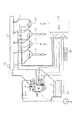
図1に、本実施形態にかかるエンジンシステムの全体構成を示す。 FIG. 1 shows the overall configuration of the engine system according to the present embodiment.
図示されるように、燃料タンク2内の燃料は、燃料フィルタ4を介して燃料ポンプ6によって汲み上げられる。この燃料ポンプ6は、ディーゼル機関の出力軸であるクランク軸8から動力を付与されて燃料を吐出するものである。詳しくは、燃料ポンプ6は、吸入調量弁10を備えており、この吸入調量弁10が操作されることで、外部に吐出される燃料量が決定される。また、燃料ポンプ6は、2つのプランジャを備えており、これらプランジャが上死点及び下死点間を往復運動することで、燃料が吸入及び吐出される。
As shown in the figure, the fuel in the
燃料ポンプ6からの燃料は、コモンレール12に加圧供給(圧送)される。コモンレール12は、燃料ポンプ6から圧送された燃料を高圧状態で蓄え、これを高圧燃料通路14を介して各気筒(ここでは、4気筒を例示)の燃料噴射弁16に供給する。なお、燃料噴射弁16は、低圧燃料通路18を介して燃料タンク2と接続されている。
The fuel from the fuel pump 6 is pressurized and supplied (pressure fed) to the common rail 12. The common rail 12 stores the fuel pumped from the fuel pump 6 in a high pressure state and supplies the fuel to the
上記エンジンシステムは、コモンレール12内の燃圧を検出する燃圧センサ20や、クランク軸8の回転角度を検出するクランク角センサ22、燃料ポンプ6内の燃料の温度を検出する燃温センサ24等、ディーゼル機関の運転状態等を検出する各種センサを備えている。更に、エンジンシステムは、ユーザによる加速要求に応じて操作されるアクセルペダルの操作量を検出するアクセルセンサ26を備えている。
The engine system includes a
一方、電子制御装置(ECU30)は、マイクロコンピュータを主体として構成され、上記各種センサの検出結果を取り込み、これに基づきディーゼル機関の出力を制御するものである。 On the other hand, the electronic control unit (ECU 30) is composed mainly of a microcomputer, takes in the detection results of the various sensors, and controls the output of the diesel engine based on this.
上記ECU30は、ディーゼル機関の出力制御を適切に行なうべく、燃料噴射制御を行う。そして、この燃料噴射制御に際しては、コモンレール12内の燃圧を、ディーゼル機関の運転状態等に応じて設定される目標燃圧にフィードバック制御する。以下、これについて図2に基づき説明する。 The ECU 30 performs fuel injection control so as to appropriately control the output of the diesel engine. In this fuel injection control, the fuel pressure in the common rail 12 is feedback-controlled to a target fuel pressure that is set according to the operating state of the diesel engine. Hereinafter, this will be described with reference to FIG.
図2に、上記コモンレール12内の燃圧の制御にかかる処理の手順を示す。この処理は、ECU30により、例えば所定周期で繰り返し実行される。
FIG. 2 shows a processing procedure for controlling the fuel pressure in the common rail 12. This process is repeatedly executed by the
この一連の処理では、まずステップS10において、アクセルセンサ26によって検出されるアクセルペダルの操作量と、要求される噴射量(要求噴射量)とに基づきコモンレール12内の燃圧の目標値(目標燃圧)を算出する。ここで、要求噴射量は、アクセルペダルの操作量に応じて要求される出力トルクを生成するための噴射量である。この要求噴射量は、クランク角センサ22によって検出されるクランク軸8の回転速度とアクセルペダルの操作量とに基づき、図示しない別のロジックにて算出される。
In this series of processing, first, in step S10, the target value (target fuel pressure) of the fuel pressure in the common rail 12 based on the accelerator pedal operation amount detected by the
続くステップS12では、燃圧センサ20によって検出される燃圧(実際の燃圧)と、目標燃圧との差に基づき、燃料ポンプ6の吐出量の指令値(指令吐出量)を算出する。この吐出量の算出は、具体的には、検出される燃圧を目標燃圧へとフィードバック制御すべく、PID制御に基づき行われる。すなわち、上記差に基づき比例項、微分項、積分項を算出し、これらから指令吐出量を算出する。ただし、これら比例項、微分項、積分項に基づき算出される指令吐出量を、燃温センサ24によって検出される燃料の温度等に基づき補正することで最終的な指令吐出量とすることが望ましい。
In the subsequent step S12, the command value (command discharge amount) of the discharge amount of the fuel pump 6 is calculated based on the difference between the fuel pressure (actual fuel pressure) detected by the
続くステップS14では、上記ステップS12において算出される指令吐出量に応じた燃料ポンプ6の駆動電流値(詳しくは、吸入調量弁10の駆動電流値)を算出する。本実施形態にかかる吸入調量弁10は、ノーマリーオープンタイプのものであるため、吐出量と駆動電流値との間には、図3に例示する関係がある。すなわち、駆動電流値を大きくするほど燃料ポンプ6の吐出量が減少する。 In the subsequent step S14, the drive current value of the fuel pump 6 (specifically, the drive current value of the intake metering valve 10) corresponding to the command discharge amount calculated in step S12 is calculated. Since the intake metering valve 10 according to the present embodiment is a normally open type, there is a relationship illustrated in FIG. 3 between the discharge amount and the drive current value. That is, the discharge amount of the fuel pump 6 decreases as the drive current value increases.
こうして駆動電流値が算出されると、ステップS16において、算出される駆動電流値に基づき燃料ポンプ(詳しくは、吸入調量弁10)を操作する。 When the drive current value is calculated in this way, in step S16, the fuel pump (specifically, the intake metering valve 10) is operated based on the calculated drive current value.
上記態様にてコモンレール12内の燃圧を目標燃圧に制御することが可能となる。こうして制御されるコモンレール12内の燃圧と、上記要求噴射量とに基づき、燃料噴射弁16に対する指令噴射期間を算出することで、燃料噴射制御を行うことができる。この指令噴射期間によって要求噴射量の燃料を精度良く噴射することができるためには、燃料噴射の期間と圧送期間とが重複しないことが望ましい。そこで、本実施形態では、上記要求噴射量の噴射の期間と圧送期間とが重ならないように図4に示す設定がなされている。
In the above aspect, the fuel pressure in the common rail 12 can be controlled to the target fuel pressure. Fuel injection control can be performed by calculating a command injection period for the
図4(a)は、1番気筒の燃料噴射弁16に対する操作信号を示し、図4(b)は、2番気筒の燃料噴射弁16に対する操作信号を示し、図4(c)は、3番気筒の燃料噴射弁16に対する操作信号を示し、図4(d)は、4番気筒の燃料噴射弁16に対する操作信号を示している。また、図4(e)は、燃料ポンプ6の一方のプランジャ(第1プランジャ)による燃料の吐出態様を示し、図4(f)は、燃料ポンプ6の他方のプランジャ(第2プランジャ)による燃料の吐出態様を示す。
4A shows an operation signal for the
図示されるように、本実施形態では、燃料ポンプ6からコモンレール12への燃料の圧送と、燃料噴射弁16を介した燃料噴射とを一対一に対応付ける同期式システムを採用している。そして、燃料噴射の期間と圧送期間とが重複しないように、各プランジャの圧送上死点を各気筒の圧縮上死点よりも進角させている。これにより、圧送によるコモンレール12内の燃圧の上昇が収まり、燃圧が安定したときに燃料噴射を行なうことができる。なお、この図4では、便宜上、アクセルペダルの操作量に応じた出力トルクを生成するためのメインとなる噴射であるメイン噴射についての操作信号のみを記載している。しかし、実際には、本実施形態では、メイン噴射後の着火時期の遅れを短縮して窒素酸化物(NOx)の発生を抑制し、燃焼音及び振動を低減するプレ噴射や、微粒子物質(PM)を再燃焼させるアフタ噴射、排気の温度を制御して、ディーゼルパティキュレートフィルタ(DPF)等のディーゼル機関の後処理装置を再生させるポスト噴射等を更に行なう。このため、プレ噴射の指令噴射開始時期の最大進角値よりもプランジャの上死点が進角となるように設定されている。これにより、プレ噴射やメイン噴射、更には、アフタ噴射の期間と圧送期間との重複を回避する。
As shown in the figure, the present embodiment employs a synchronous system in which fuel pressure from the fuel pump 6 to the common rail 12 and fuel injection through the
ただし、上記ポスト噴射は、通常、メイン噴射から大きく遅角して噴射される。このため、図4(c)に一点鎖線にて示すように、ポスト噴射のタイミングは、プランジャの圧送上死点よりも進角側であって且つ同圧送上死点に近接することとなる。このため、図5に示すように、コモンレール12への燃料の圧送量(燃料ポンプ6の吐出量)によっては、ポスト噴射の期間と圧送期間とが重複することとなる。 However, the post-injection is usually injected with a large delay from the main injection. For this reason, as shown by a one-dot chain line in FIG. 4C, the timing of the post injection is on the advance side of the pressure-feeding top dead center of the plunger and close to the pressure-feeding top dead center. For this reason, as shown in FIG. 5, the post-injection period and the pressure-feed period overlap depending on the pressure-feed amount of fuel to the common rail 12 (discharge amount of the fuel pump 6).
図5(a)は、任意の気筒の燃料噴射弁16の操作信号を示し、図5(b)は、同気筒の実際の噴射率を示し、図5(c)は、コモンレール12内の燃圧を示す。図5(c)では、圧送量が多量であるときの燃圧の上昇態様を実線で示し、圧送量が少量であるときの燃圧の挙動を2点鎖線にて示し、圧送量が上記多量と少量との中間であるときの燃圧の挙動を1点させにて示した。図示されるように、圧送量に応じてポスト噴射の実際の噴射期間と圧送期間とが重複したり重複しなかったりする。
5A shows an operation signal of the
ちなみに、この圧送量の変化は、先の図2のステップS12に示した処理によって生じる。このステップS12に示した処理によって算出される吐出量と他のパラメータとの関係を図6に示す。 Incidentally, the change in the pumping amount is caused by the process shown in step S12 of FIG. FIG. 6 shows the relationship between the discharge amount calculated by the process shown in step S12 and other parameters.
図6(a)は、要求噴射量と燃圧と吐出量との関係である。図示されるように、噴射量が多いほど吐出量が多くなる。これは、噴射量が多いほど、燃料噴射弁16を介してコモンレール12からディーゼル機関の燃焼室に噴射される燃料量が多くなるためである。また、同一の噴射量であっても燃圧が高いほど吐出量が増大する。これは、燃圧が高いほど、燃料噴射弁16を介して高圧燃料通路14から低圧燃料通路18へと流出する燃料量であるリーク燃料量が増大するためである。更に、図6(b)に示すように、同一の噴射量であっても、回転速度が大きいほど吐出量が増大する。
FIG. 6A shows the relationship among the required injection amount, the fuel pressure, and the discharge amount. As shown in the figure, the discharge amount increases as the injection amount increases. This is because as the injection amount increases, the amount of fuel injected from the common rail 12 into the combustion chamber of the diesel engine via the
このように、吐出量は、ディーゼル機関の運転状態に応じて大きく変化する傾向にあり、このため先の図5(c)に示したように圧送期間とポスト噴射の実際の噴射期間との重複態様が大きく変化することとなる。そして、ポスト噴射の実際の噴射期間と圧送期間との重複態様が大きく変化すると、ポスト噴射の制御精度の低下を招くおそれがある。 Thus, the discharge amount tends to change greatly depending on the operating state of the diesel engine. Therefore, as shown in FIG. 5C, the overlap between the pumping period and the actual injection period of the post-injection. The aspect will change greatly. And if the overlap mode of the actual injection period and the pumping period of post-injection changes greatly, there is a risk that the post-injection control accuracy will be lowered.
そこで本実施形態では、燃料ポンプ6の駆動電流値に基づき、ポスト噴射の期間と圧送期間との重複の有無を判断するとともに、重複するときには、燃圧センサ20によって検出される燃圧に対するポスト噴射の期間における燃圧の上昇に応じて指令噴射期間を設定する。以下、これについて詳述する。
Accordingly, in the present embodiment, based on the drive current value of the fuel pump 6, it is determined whether or not the post injection period and the pumping period overlap, and when they overlap, the post injection period with respect to the fuel pressure detected by the
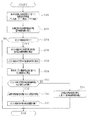
図7に、本実施形態にかかる燃料噴射制御の処理手順を示す。この処理は、ECU30により、例えば所定周期で繰り返し実行される。
FIG. 7 shows a processing procedure of fuel injection control according to the present embodiment. This process is repeatedly executed by the
この一連の処理では、まずステップS20において、アクセルペダルの操作量に応じた上記要求噴射量と、クランク軸8の回転速度とに基づき、要求噴射量の燃料を分割して噴射する噴射段数を算出する。ここで、この噴射段数が「1」であるときには、メイン噴射のみを行うこととなり、噴射段数が「2」以上であるときには、メイン噴射に加えて、プレ噴射やアフタ噴射を行なうこととなる。なお、噴射段数が「2」以上であるときには、このステップS20において、各噴射段の噴射量を算出する。 In this series of processes, first, in step S20, the number of injection stages for dividing and injecting the fuel of the required injection amount is calculated based on the required injection amount corresponding to the operation amount of the accelerator pedal and the rotational speed of the crankshaft 8. To do. Here, when the number of injection stages is “1”, only main injection is performed, and when the number of injection stages is “2” or more, pre-injection and after-injection are performed in addition to the main injection. When the number of injection stages is “2” or more, the injection amount of each injection stage is calculated in step S20.
続くステップS22では、ステップS20にて算出される噴射段数の各噴射段の指令噴射期間と指令噴射開始時期とを算出する。続くステップS24では、ポスト噴射を行なう要求があるか否かを判断する。この要求は、図示しない別のロジックにて生成されるものである。 In the subsequent step S22, a command injection period and a command injection start timing for each injection stage of the number of injection stages calculated in step S20 are calculated. In a succeeding step S24, it is determined whether or not there is a request for performing the post injection. This request is generated by another logic (not shown).
そして、ポスト噴射の要求があると判断されると、ステップS26において、ポスト噴射の指令噴射開始時期と、仮の指令噴射期間とを算出する。ここで、指令噴射開始時期は、クランク軸8の回転速度と、上記要求噴射量とに基づき算出される。 If it is determined that there is a request for post-injection, a post-injection command injection start timing and a temporary command injection period are calculated in step S26. Here, the command injection start timing is calculated based on the rotational speed of the crankshaft 8 and the required injection amount.
また、仮の指令噴射期間は、回転速度と要求噴射量とに基づき定まるポスト噴射の噴射量と、燃圧センサ20によって検出される燃圧の最新の検出値とに応じて算出される。より正確には、上記特許文献1に記載された手法を用いる。すなわち、ステップS26の処理時における燃圧センサ20の検出値NPCnと、同ステップS26の前回の処理時における燃圧センサ20の検出値NPC(n−1)と、前回のポスト噴射の指令噴射開始時期における燃圧センサ20の検出値NPCM(n−1)とを用いて、見込み圧NPCFを「NPCn+NPCM(n−1)−NPC(n−1)」として算出する。そして、この見込み圧NPCFと、ポスト噴射の噴射量とに基づき、仮の指令噴射期間を算出する。
The temporary command injection period is calculated according to the post-injection injection amount determined based on the rotation speed and the required injection amount and the latest detected value of the fuel pressure detected by the
続くステップS28においては、ポスト噴射の実際の噴射開始時期を算出する。これは、燃料噴射弁16には、通常、応答遅れがあり、燃料噴射弁16の開弁操作から実際に燃料の噴射が開始されるまでに遅延が生じるために行なう処理である。この応答遅れは、コモンレール12内の燃圧に依存する。このため、まず指令噴射開始時期に対する実際の噴射開始時期の遅延時間を、ポスト噴射の前段の噴射からポスト噴射までの時間間隔と、燃圧センサ20によって検出される燃圧とに基づき算出する。ここで、ポスト噴射の前段の噴射からポスト噴射までの時間間隔を用いるのは、前段の噴射によって生じる圧力脈動によって遅延時間が変化するためである。また、前段の噴射とは、アフタ噴射が行なわれるときには、アフタ噴射を意味し、アフタ噴射が行なわれないときには、メイン噴射を意味する。こうして遅延時間が算出されると、指令噴射開始時期と遅延時間とに基づき、実際の噴射開始時期を算出する。
In the subsequent step S28, the actual injection start timing of the post injection is calculated. This is a process performed because the
続くステップS30においては、燃料ポンプ6の駆動電流値に基づき、燃料ポンプ6による燃料の圧送開始点を算出する。ここでは、圧送開始点を、圧送の開始から、対応する気筒の圧送上死点となるまでに要する時間として定義し、圧送開始点と駆動電流値との関係を定めた図8(a)に示すマップを用いて圧送開始点を算出する。図示されるように、駆動電流値が大きいほど、圧送開始点が小さくなる。これは、駆動電流値が大きいほど吐出量が少なくなるため、圧送の開始が圧送上死点に近づき、ひいては、圧送開始から圧縮上死点に到達するまでの時間が短くなるためである。また、同一の駆動電流値であっても、クランク軸8の回転速度が小さいほど圧送開始点が大きくなる。これは、回転速度が小さいほど同一のクランク角度領域の回転に要する時間が長くなるためである。 In the subsequent step S30, a fuel pumping start point of the fuel pump 6 is calculated based on the drive current value of the fuel pump 6. Here, the pumping start point is defined as the time required from the start of pumping to the pumping top dead center of the corresponding cylinder, and the relationship between the pumping start point and the drive current value is defined in FIG. The pumping start point is calculated using the map shown. As shown in the figure, the larger the drive current value, the smaller the pumping start point. This is because the larger the drive current value, the smaller the discharge amount, so that the start of pumping approaches the pumping top dead center, and consequently the time from the start of pumping until reaching the compression top dead center is shortened. Even with the same drive current value, the lower the rotational speed of the crankshaft 8, the greater the pumping start point. This is because the time required for rotation in the same crank angle region increases as the rotational speed decreases.
続く先の図7に示すステップS32においては、ポスト噴射の実際の噴射開始時期と圧送期間とが重複するか否かを判断する。この判断は、例えば以下のようにして行なう。まず、上記ステップS28において、ポスト噴射の指令噴射時期からその気筒の圧縮上死点までのクランク角度を時間換算し、これから実際の噴射開始時期までの遅延時間を減算することで、圧縮上死点に対する先行時間として、実際の噴射開始時期を算出する。そして、この先行時間と、ステップS30にて算出される圧送開始の圧縮上死点に対する先行時間との比較に基づき、実際の噴射開始時期の先行時間の方が短いときに重複すると判断する。 In the subsequent step S32 shown in FIG. 7, it is determined whether or not the actual injection start timing of the post injection overlaps with the pumping period. This determination is performed as follows, for example. First, in step S28, the crank angle from the post-injection command injection timing to the compression top dead center of the cylinder is time-converted, and the delay time from the actual injection start timing to this is subtracted to thereby compress the top dead center. The actual injection start time is calculated as the preceding time for. Then, based on a comparison between the preceding time and the preceding time with respect to the compression top dead center at the pumping start calculated in step S30, it is determined that the preceding time at the actual injection start timing is overlapped.
そして、重複していないと判断されるときには、ステップS34において、ポスト噴射の指令噴射開始時期における燃圧センサ20の検出値NPCMnに基づき、指令噴射期間を補正する。すなわち、指令噴射開始時期における検出値NPCMnと、ポスト噴射の噴射量とに基づき、指令噴射期間を再算出し、これを指令噴射期間として用いることで指令噴射終了時期を定める。ただし、指令噴射開始時期における検出値NPCMnと、上記ステップS26における検出値NPCnとの差の絶対値が予め定められた閾値より大きいときには、検出値NPCMnにノイズが混入しているおそれがあるとして、上記仮の指令噴射期間を最終的な指令噴射期間とする。
When it is determined that there is no overlap, the command injection period is corrected in step S34 based on the detection value NPCMn of the
一方、ステップS32において重複がある旨判断されるときには、ステップS36に移行する。ここでは、実際の噴射開始時期におけるコモンレール12内の燃圧を算出する。これは、指令噴射開始時期における燃圧センサ20の検出値NPCMnと、指令噴射開始時期から実際の噴射開始時期までの間の燃圧の上昇量とに基づき算出される。この燃圧の上昇量の算出は、図8(b)に示すマップに基づき行なう。図示されるマップは、クランク軸8の回転角度にて定義される2点(始点及び終点)と、これら2点間の移行に伴う燃圧の上昇量との関係を定めるものである。すなわち、燃料ポンプ6の各プランジャはクランク軸8と同期して回転するものであるため、クランク軸8の回転角度によって、始点と終点とを定めることで、その間のプランジャの変位態様を把握することができる。このため、始点と終点とを定めることで、その間に燃料ポンプ6から吐出される燃料量が定まり、ひいては、コモンレール12内の燃圧の上昇量が定まることとなる。上記ステップS36では、指令噴射開始時期と圧送開始点とのうちの遅角側にある方のクランク角度を始点とし、実際の噴射開始時期のクランク角度を終点として、始点から終点までの燃圧の上昇量を図8(b)に示すマップにて算出する。こうして算出される上昇量に検出値NPCMnを加算することで、実際の噴射開始時期における燃圧を算出する。
On the other hand, when it is determined in step S32 that there is an overlap, the process proceeds to step S36. Here, the fuel pressure in the common rail 12 at the actual injection start timing is calculated. This is calculated based on the detected value NPCMn of the
続いて、先の図7のステップS38では、上記ステップS36にて算出された燃圧に基づき、上記仮の指令噴射期間を補正する。すなわち、新たに算出された燃圧と、ポスト噴射の噴射量とに基づき、指令噴射期間を再算出する。 Subsequently, in step S38 of FIG. 7, the temporary command injection period is corrected based on the fuel pressure calculated in step S36. That is, the command injection period is recalculated based on the newly calculated fuel pressure and the post injection amount.
なお、上記ステップS24においてポスト噴射の要求がないと判断されるときや、ステップS34、S38の処理が完了するときには、この一連の処理を一旦終了する。ちなみに、ステップS22における指令噴射期間の算出も、実際には、ステップS26及びステップS34の処理と同様の処理にて算出することが望ましい。 When it is determined in step S24 that there is no post injection request, or when the processes in steps S34 and S38 are completed, this series of processes is temporarily terminated. Incidentally, the calculation of the command injection period in step S22 is actually preferably performed by the same processing as the processing in steps S26 and S34.
図9に、先の図7に示した処理によるポスト噴射の指令噴射期間の設定態様について示す。図9(a)は、燃料噴射弁16に対する操作信号を示し、図9(b)は、実際の噴射率を示し、図9(c)は、コモンレール12内の燃圧の挙動を示す。また、図中、左側には圧送量が多量である場合について、また、右側には圧送量が少量である場合について、更に中央には圧送量が上記多量と少量との間の量である場合について示している。ちなみに、図9(c)に示す燃圧の挙動は、先の図5(c)と対応している。
FIG. 9 shows how the post injection command injection period is set by the process shown in FIG. 9A shows an operation signal for the
圧送量が多量である場合には、圧送開始時a1の後に、指令噴射開始時期b1が訪れることとなる。このため、指令噴射開始時期b1における燃圧の検出値NPCM1と、指令噴射開始時期b1から実際の噴射開始時期c1までの燃圧の上昇量ΔP1との和として、実際の噴射開始時期における燃圧が算出される。 When the pumping amount is large, the command injection start timing b1 comes after the pumping start time a1. Therefore, the fuel pressure at the actual injection start timing is calculated as the sum of the detected fuel pressure value NPCM1 at the command injection start timing b1 and the fuel pressure increase ΔP1 from the command injection start timing b1 to the actual injection start timing c1. The
圧送量が中である場合には、指令噴射開始時期b2と実際の噴射開始時期c2との間に、圧送開始時a2があることとなる。そして、指令噴射開始時期bにおける燃圧の検出値NPCM2と、指令噴射開始時期b1から実際の噴射開始時期c2までの燃圧の上昇量ΔP2との和として、実際の噴射開始時期における燃圧が算出される。 When the pumping amount is medium, there is a pumping start time a2 between the command injection start timing b2 and the actual injection start timing c2. Then, the fuel pressure at the actual injection start timing is calculated as the sum of the fuel pressure detection value NPCM2 at the command injection start timing b and the fuel pressure increase ΔP2 from the command injection start timing b1 to the actual injection start timing c2. .
圧送量が小である場合には、実際の噴射開始時期c3の後に圧送開始時a3となる。このため、指令噴射開始時期b3における燃圧の検出値NPCM3に基づき、指令噴射期間が算出される。 When the pumping amount is small, the pumping start time a3 comes after the actual injection start timing c3. Therefore, the command injection period is calculated based on the detected value NPCM3 of the fuel pressure at the command injection start timing b3.
以上詳述した本実施形態によれば、以下の効果が得られるようになる。 According to the embodiment described in detail above, the following effects can be obtained.
(1)燃料ポンプの駆動電流値に基づき、ポスト噴射の実際の噴射開始時期と圧送期間とが重複するか否かを判断し、重複すると判断されるとき、実際の噴射開始時期における燃圧を算出して、同燃圧に基づき指令噴射期間を算出した。これにより、実際の噴射開始時期と圧送期間とが重複するときには、検出される燃圧に対して圧送によりコモンレール12内の燃圧が変化することに鑑み、この変化に応じて指令噴射期間を設定することができ、要求される噴射量を精度良く噴射することができる。 (1) Based on the drive current value of the fuel pump, it is determined whether or not the actual injection start timing of post-injection overlaps with the pumping period, and when it is determined that there is an overlap, the fuel pressure at the actual injection start timing is calculated Then, the command injection period was calculated based on the fuel pressure. Thereby, when the actual injection start timing and the pumping period overlap, in consideration of the fact that the fuel pressure in the common rail 12 changes due to pumping with respect to the detected fuel pressure, the command injection period is set according to this change. The required injection amount can be injected with high accuracy.
(2)ポスト噴射の実際の噴射開始時期を、該燃料噴射の前段の噴射からの時間間隔と検出される燃圧とに基づき算出した。これにより、実際の噴射開始時期を精度良く算出することができる。 (2) The actual injection start timing of the post injection was calculated based on the time interval from the preceding injection of the fuel injection and the detected fuel pressure. Thereby, the actual injection start timing can be calculated with high accuracy.
(3)燃料ポンプ6による燃料の圧送開始点を算出するに際し、燃料ポンプ6の駆動電流値に加えて、クランク軸8の回転速度を用いた。これにより、圧送開始点をより高精度に算出することができる。 (3) In calculating the fuel pumping start point of the fuel pump 6, the rotational speed of the crankshaft 8 was used in addition to the drive current value of the fuel pump 6. Thereby, a pumping start point can be calculated with higher accuracy.
(4)重複の判断に先立ち、ポスト噴射の指令噴射期間を仮に算出した。これにより、実際の噴射開始時期と圧送期間とが重複しないときであって、指令噴射開始時期における燃圧の検出値の信頼性が低いと判断されるときには、仮の指令噴射期間を用いて燃料噴射を行なうことができる。特に、この仮の指令噴射期間は、前回の指令噴射開始時期における燃圧の検出値NPCM(n−1)に基づき算出されるために、この仮の指令噴射期間を用いることで、燃料噴射の制御精度を高く維持することができる。 (4) Prior to determining overlap, a command injection period for post injection was temporarily calculated. Thus, when the actual injection start timing and the pumping period do not overlap and it is determined that the reliability of the detected value of the fuel pressure at the command injection start timing is low, the fuel injection is performed using the temporary command injection period. Can be performed. In particular, since this temporary command injection period is calculated based on the detected value NPCM (n-1) of the fuel pressure at the previous command injection start timing, the control of fuel injection is performed by using this temporary command injection period. High accuracy can be maintained.
(5)燃料噴射装置に同期システムを採用し、メイン噴射期間が圧送期間と重複しないように設定した。これにより、メイン噴射を簡易且つ高精度に制御することができる。 (5) A synchronous system was adopted for the fuel injection device, and the main injection period was set not to overlap with the pumping period. Thereby, the main injection can be controlled easily and with high accuracy.
(第2の実施形態)
以下、第2の実施形態について、先の第1の実施形態との相違点を中心に、図面を参照しつつ説明する。
(Second Embodiment)
Hereinafter, the second embodiment will be described with reference to the drawings with a focus on differences from the first embodiment.
本実施形態では、ポスト噴射の実際の噴射開始時期から実際の噴射終了時期までの間のコモンレール12内の燃圧の平均値を算出(推定)することで、ポスト噴射の指令噴射期間を設定する。以下、図10を用いて、本実施形態にかかる指令噴射期間の設定の手法を説明する。 In the present embodiment, the post-injection command injection period is set by calculating (estimating) the average value of the fuel pressure in the common rail 12 from the actual injection start timing to the actual injection end timing of the post injection. Hereinafter, the method of setting the command injection period according to the present embodiment will be described with reference to FIG.
図10(a)は、燃料噴射弁16の操作信号を示し、図10(b)は、実際の噴射率を示し、図10(c)は、コモンレール12内の燃圧の挙動を示す。
10A shows the operation signal of the
図示されるように、先の図7に示した処理によって、圧送開始時aよりも実際の噴射開始時期cが後となると判断されるときには、実際の噴射開始時期cから実際の噴射終了時期dまでの燃圧の平均値を算出する。ここで、実際の噴射終了時期dは、先の図7のステップS26によって算出される指令噴射期間と、指令噴射開始時期と、指令噴射開始時期bにおける燃圧の検出値NPCMとに基づき算出される。すなわち、実際の噴射終了時期dは、燃料噴射弁16の応答遅れに起因して、指令噴射期間の終了時よりも遅れる傾向にある。そして、この応答遅れは、コモンレール12内の燃圧に依存する。このため、実際の噴射終了時期は、燃圧の検出値NPCMによって、指令噴射開始時期と指令噴射期間とによって定まる指令噴射期間の終了時期に対する応答遅れ量を把握することで算出することができる。なお、実際には、この実際の噴射終了時期は、マップ演算される。
As shown in the figure, when it is determined by the process shown in FIG. 7 that the actual injection start timing c is later than the pumping start timing a, the actual injection end timing d is changed from the actual injection start timing c. The average value of the fuel pressure up to is calculated. Here, the actual injection end timing d is calculated based on the command injection period calculated in step S26 of FIG. 7, the command injection start timing, and the detected value NPCM of the fuel pressure at the command injection start timing b. . That is, the actual injection end timing d tends to be delayed from the end of the command injection period due to the response delay of the
上記実際の噴射開始時期cにおける燃圧Pcは、先の図7の処理を説明する際に記載したように、先の図8(b)に示したマップを用いて算出する。同様に、実際の噴射終了時期dにおける燃圧Pdも、先の図8(d)に示したマップを用いて算出することができる。すなわち、始点を指令噴射開始時期bとし、終点を実際の噴射終了時期dとすることで、始点から終点までの燃圧の上昇量を算出し、これに検出値NPCMを加算することで算出することができる。 The fuel pressure Pc at the actual injection start timing c is calculated using the map shown in FIG. 8B as described in the description of the processing of FIG. Similarly, the fuel pressure Pd at the actual injection end timing d can also be calculated using the map shown in FIG. That is, the start point is set as the command injection start timing b and the end point is set as the actual injection end timing d, so that the amount of increase in fuel pressure from the start point to the end point is calculated, and the detection value NPCM is added to this. Can do.
こうして実際の噴射開始時期cにおける燃圧Pcと、実際の噴射終了時期dにおける燃圧Pdとが算出されると、これら燃圧Pcと燃圧Pdとの平均値を算出する。この平均値は、簡易的に「(Pc+Pd)/2」としてもよい。また、これに代えて、加重平均値「Wc×Pc+Wd×Pd:Wc+Wd=1」としてもよい。ここで、重みWc、Wdは、クランク角度に応じて吐出量が変化することに起因して燃圧の上昇速度が変化することに基づき定められる。 When the fuel pressure Pc at the actual injection start timing c and the fuel pressure Pd at the actual injection end timing d are thus calculated, an average value of the fuel pressure Pc and the fuel pressure Pd is calculated. This average value may be simply “(Pc + Pd) / 2”. Alternatively, a weighted average value “Wc × Pc + Wd × Pd: Wc + Wd = 1” may be used. Here, the weights Wc and Wd are determined based on the change in the fuel pressure increase rate due to the change in the discharge amount according to the crank angle.
こうして燃圧Pcと燃圧Pdとの平均値が算出されると、先の図7のステップS38において、この平均値とポスト噴射の噴射量とに基づき、指令噴射期間を算出する(ステップS26において算出される仮の指令噴射期間を補正する)。 When the average value of the fuel pressure Pc and the fuel pressure Pd is calculated in this way, in step S38 of FIG. 7, the command injection period is calculated based on the average value and the post-injection injection amount (calculated in step S26). The provisional command injection period is corrected).
以上説明した本実施形態によれば、先の第1の実施形態の上記(1)〜(5)の効果に加えて、更に以下の効果が得られるようになる。 According to this embodiment described above, in addition to the effects (1) to (5) of the first embodiment, the following effects can be obtained.
(6)実際の噴射開始時期から実際の噴射終了時期までの間のコモンレール12内の燃圧の平均値を算出することで、指令噴射期間の設定(仮の指令噴射期間の補正)を行なった。これにより、実際の噴射期間におけるコモンレール12内の燃圧に応じて指令噴射期間を適切に設定することができる。 (6) The command injection period is set (temporary command injection period is corrected) by calculating the average value of the fuel pressure in the common rail 12 from the actual injection start timing to the actual injection end timing. Thereby, the command injection period can be appropriately set according to the fuel pressure in the common rail 12 in the actual injection period.
(第3の実施形態)
以下、第3の実施形態について、先の第1の実施形態との相違点を中心に、図面を参照しつつ説明する。
(Third embodiment)
Hereinafter, the third embodiment will be described with reference to the drawings with a focus on differences from the first embodiment.
本実施形態では、図11に示すように、ディーゼル機関を5気筒とするとともに、燃料噴射装置に非同期システムを採用する。図11(a)〜図11(e)に、1番気筒から5番気筒の燃料噴射弁16に対するメイン噴射のための操作信号をそれぞれ示す。また図11(f)に、第1プランジャによる燃料の吸入、吐出(圧送)態様の推移を、図11(g)に、第2プランジャによる燃料の吸入、吐出(圧送)態様の推移をそれぞれ示す。
In the present embodiment, as shown in FIG. 11, the diesel engine has five cylinders and an asynchronous system is adopted for the fuel injection device. FIGS. 11A to 11E show operation signals for main injection for the
本実施形態では、第1プランジャ又は第2プランジャによる燃料の圧送の周期が「480°CA」となっており、燃料ポンプ6による燃料の圧送周期は「240°CA」となっている。一方、燃料噴射が行なわれる周期は、「144°CA」毎となっている。このため、本実施形態における燃料噴射装置は、第1プランジャや第2プランジャによる圧送タイミングと各気筒の燃料噴射のタイミングとが一対一に対応しない非同期システムとなっている。 In the present embodiment, the fuel pumping cycle by the first plunger or the second plunger is “480 ° CA”, and the fuel pumping cycle by the fuel pump 6 is “240 ° CA”. On the other hand, the cycle in which the fuel is injected is every “144 ° CA”. For this reason, the fuel injection device in the present embodiment is an asynchronous system in which the pressure feeding timing by the first plunger or the second plunger and the fuel injection timing of each cylinder do not correspond one to one.
このため、本実施形態では、メイン噴射についても、噴射期間と圧送期間とが重複し得る。そこで、メイン噴射についても、重複があるときには、指令噴射期間を実際の噴射開始時期の燃圧の算出値(推定値)基づき設定するようにする。以下、これについて図12を用いて説明する。 For this reason, in this embodiment, an injection period and a pumping period may overlap also about main injection. Therefore, when there is an overlap in the main injection, the command injection period is set based on the calculated value (estimated value) of the fuel pressure at the actual injection start timing. Hereinafter, this will be described with reference to FIG.
図12に、本実施形態にかかる燃料噴射制御の処理手順を示す。この処理は、ECU30により、例えば所定周期で繰り返し実行される。
FIG. 12 shows a processing procedure of fuel injection control according to the present embodiment. This process is repeatedly executed by the
この一連の処理では、まずステップS40において、指令噴射期間と指令噴射開始時期とを算出する。ここで指令噴射期間は、燃圧センサ20による燃圧の最新の検出値と、メイン噴射の噴射量とに基づき算出すればよい。続くステップS42では、実際の噴射開始時期を算出する。これは、先の図7のステップS28と同様の処理によって行なうことができる。続くステップS44では、燃料ポンプ6の駆動電流値に基づき、燃料噴射を行なう気筒の圧縮上死点以前であって同圧縮上死点にもっとも近いものの圧送開始点を算出する。ここでは、圧送開始から圧送上死点に到達するまでの時間と駆動電流値及び回転速度との関係を定めるマップを用いて、圧送開始点を上記時間として算出する。
In this series of processes, first, in step S40, a command injection period and a command injection start timing are calculated. Here, the command injection period may be calculated based on the latest detected value of the fuel pressure by the
続くステップS46では、燃料噴射を行なう気筒の圧縮上死点と、上記ステップS42の圧送開始と対応する圧送上死点との間隔をクランク角度で算出する。 In the subsequent step S46, the interval between the compression top dead center of the cylinder performing fuel injection and the pressure top dead center corresponding to the start of pressure feeding in step S42 is calculated as a crank angle.
続くステップS48では、実際の噴射開始時期と圧送期間とが重複するか否かを判断する。この判断は、次のようにして行なえばよい。(イ)ステップS46で算出された圧送上死点と圧縮上死点とのクランク角度間隔を、そのときのクランク軸8の回転速度に基づき、時間間隔に変換する。(ロ)この時間間隔にステップS44で算出される圧送開始から圧送上死点までに要する時間を加算する。(ハ)上記ステップS42にて算出される実際の噴射開始時期を圧縮上死点からの時間に換算する。(ニ)上記(ロ)にて算出される時間が、上記(ハ)にて換算される時間よりも長くて且つ圧送上死点が実際の噴射開始時期よりも後にくるときに、重複すると判断する。 In subsequent step S48, it is determined whether or not the actual injection start timing and the pumping period overlap. This determination may be made as follows. (A) The crank angle interval between the pumping top dead center and the compression top dead center calculated in step S46 is converted into a time interval based on the rotational speed of the crankshaft 8 at that time. (B) The time required from the pumping start to the pumping top dead center calculated in step S44 is added to this time interval. (C) The actual injection start timing calculated in step S42 is converted into a time from the compression top dead center. (D) When the time calculated in (b) above is longer than the time converted in (c) above and the pumping top dead center comes after the actual injection start timing, it is determined that they overlap. To do.
そして、実際の噴射開始時期と圧送期間とが重複すると判断されると、ステップS50において、噴射開始時期の燃圧を算出(推定)する。ここでは、先の図8(b)に示したマップに代えて、燃料ポンプ6の任意の1つのプランジャの下死点から上死点までの変位過程における任意の2点を始点及び終点として、これら始点から終点まで燃料ポンプ6が燃料を吐出するときのコモンレール12内の燃圧の上昇量を定めるマップをECU30に予め記憶しておく。詳しくは、本実施形態では圧送周期が「240°CA」であり、プランジャを2つ備えるために、任意の1つのプランジャが圧送下死点から圧送上死点まで移行する際にクランク軸8が回転する回転角度は、「240°CA」である。このため、上記マップにより、「240°CA」内の任意の角度領域の回転に伴う燃料ポンプ6の吐出による燃圧の上昇量を定める。例えば、上記圧送上死点と対応するクランク角度を「240°CA」とするとともに、圧送下死点と対応するクランク角度を「0°ca」とする。そして、上記ステップS40で算出される指令噴射開始時期と圧送開始点とのうちの遅角側となる方を、上記クランク角度に換算してこれを始点とする。また、上記ステップS42で算出される実際の噴射開始時期を、上記クランク角度に換算してこれを終点とする。これにより、上記マップを用いて、指令噴射開始時期(又は圧送開始点)から実際の噴射開始時期までの間の燃圧の上昇量を算出することができる。そして、こうして算出される燃圧の上昇量に、指令噴射開始時期における燃圧の検出値を加算することで、実際の噴射開始時期における燃圧を算出する。
When it is determined that the actual injection start timing and the pumping period overlap, in step S50, the fuel pressure at the injection start timing is calculated (estimated). Here, instead of the map shown in FIG. 8B, any two points in the displacement process from the bottom dead center to the top dead center of any one plunger of the fuel pump 6 are used as the start point and the end point. A map that determines the amount of increase in fuel pressure in the common rail 12 when the fuel pump 6 discharges fuel from the start point to the end point is stored in the
こうして実際の噴射時期における燃圧が算出されると、ステップS52において、この算出される燃圧と、燃料噴射量とに基づき指令噴射期間を設定する(上記ステップS40にて算出される指令噴射期間を補正する)。なお、ステップS48にて重複がないと判断されるときや、ステップS52の処理が完了するときには、この一連の処理を一旦終了する。 When the fuel pressure at the actual injection timing is thus calculated, in step S52, a command injection period is set based on the calculated fuel pressure and the fuel injection amount (the command injection period calculated in step S40 is corrected). To do). When it is determined in step S48 that there is no overlap, or when the process of step S52 is completed, this series of processes is temporarily ended.
以上説明した本実施形態によれば、先の第1の実施形態の上記(1)〜(3)の効果に加えて、更に以下の効果が得られるようになる。 According to the present embodiment described above, the following effects can be obtained in addition to the effects (1) to (3) of the first embodiment.
(7)プランジャの圧送下死点と圧送上死点との間の領域をクランク軸8の回転角度に対応付けるとともに、この回転角度と、燃料噴射についての各タイミングとを対応付けることで、非同期システムを採用した場合であれ、圧送開始や、圧送に伴う燃圧の上昇量を適切に算出することができる。 (7) By associating the region between the pumping bottom dead center and the pumping top dead center with the rotation angle of the crankshaft 8, and associating this rotation angle with each timing for fuel injection, the asynchronous system is Even if it is adopted, the start of pumping and the amount of increase in fuel pressure accompanying pumping can be calculated appropriately.
(その他の実施形態)
なお、上記各実施形態は、以下のように変更して実施してもよい。
(Other embodiments)
Each of the above embodiments may be modified as follows.
・上記各実施形態では、重複があると判断されるとき、実際の噴射の期間における燃圧と噴射量とから指令噴射期間を再度算出することで補正したが、既に算出されている仮の指令噴射期間を直接補正するようにしてもよい。 In each of the above embodiments, when it is determined that there is an overlap, the correction is made by calculating the command injection period again from the fuel pressure and the injection amount in the actual injection period. You may make it correct | amend a period directly.
・第1の実施形態において、先の図7のステップS22の処理のうち指令噴射期間の仮の算出にかかる処理については、これをステップS32の処理の後に行なってもよい。これにより、ステップS32の処理により重複があると判断されるときには、仮の指令噴射期間を算出する必要が生じず、ECU30の演算負荷を低減することができる。
-In 1st Embodiment, about the process concerning temporary calculation of a command injection period among the processes of step S22 of previous FIG. 7, this may be performed after the process of step S32. Thus, when it is determined that there is an overlap in the process of step S32, it is not necessary to calculate a temporary command injection period, and the calculation load on the
・上記第2の実施形態において、実際の噴射終了時期を、実際の噴射開始時期に指令噴射期間を加算することで簡易的に算出してもよい。 In the second embodiment, the actual injection end timing may be simply calculated by adding the command injection period to the actual injection start timing.
・燃圧センサ20による燃圧の検出タイミングから燃料噴射の期間のまでの間の燃圧の上昇量を算出する手法としては、先の図8(b)等に例示するマップを用いるものに限らない。例えばクランク軸8と燃料ポンプ6の各プランジャとの幾何学的関係を用いてECU30内で都度算出するようにしてもよい。
The method for calculating the amount of increase in fuel pressure from the fuel pressure detection timing by the
・上記各実施形態では、圧送開始点を駆動電流値に基づき算出したが、先の図2のステップS12に示した指令吐出量に基づき算出してもよい。ただし、先の図2に示す処理において、燃料噴射制御装置によっては、指令吐出量をPID制御等によって算出した後、この指令吐出量に基づいて駆動電流値を算出しつつも、燃料の温度等に応じて更に駆動電流値を補正するものもある。この場合には、指令吐出量と駆動電流値とが一義的に対応しないため、駆動電流値を用いる方が望ましい。また、燃圧の制御ロジックが燃料噴射制御装置の機種毎に異なることに鑑みれば、駆動電流値に基づき算出するロジックは、様々な種類の燃圧の制御ロジックに適切に対応できる汎用性の高いものといえる。 In each of the above embodiments, the pumping start point is calculated based on the drive current value, but may be calculated based on the command discharge amount shown in step S12 of FIG. However, in the processing shown in FIG. 2, depending on the fuel injection control device, after calculating the command discharge amount by PID control or the like, while calculating the drive current value based on this command discharge amount, Some of them further correct the drive current value according to the above. In this case, it is desirable to use the drive current value because the command discharge amount does not uniquely correspond to the drive current value. In addition, considering that the fuel pressure control logic varies depending on the model of the fuel injection control device, the logic that is calculated based on the drive current value is considered to be highly versatile that can appropriately handle various types of fuel pressure control logic. I can say that.
・吸入調量弁10としては、ノーマリーオープン式のものに限らず、ノーマリークローズ式のものであってもよい。 The suction metering valve 10 is not limited to a normally open type but may be a normally closed type.
・燃料ポンプ6としては、吸入調量弁10を備えるものに限らず、燃料の吐出の終了タイミングを制御するものであってもよい。この場合、駆動電流値に基づき圧送開始点ではなく、圧送終了点を算出することで重複の有無を判断する。 The fuel pump 6 is not limited to the one provided with the intake metering valve 10, and may control the fuel discharge end timing. In this case, the presence or absence of duplication is determined by calculating not the pumping start point but the pumping end point based on the drive current value.
・燃料噴射弁16としては、燃圧と指令噴射期間とによって噴射量を一義的に定めるものに限らない。例えば米国特許第6520423号明細書に記載されているように、燃料噴射弁16が、アクチュエータの変位に応じてノズルニードルのリフト量を連続的に調整可能なものであるなら、噴射期間と燃圧とによって一義的に噴射量を定めることはできない。この場合には、燃料噴射量を制御するための燃料噴射弁の操作量は、例えばアクチュエータに与えるエネルギ量とエネルギを与える期間(指令噴射期間)となり、噴射量は、燃圧とこれらエネルギ量及び指令噴射期間とによって定まる。
The
・内燃機関としては、ディーゼル機関に限らず、例えば筒内噴射式ガソリン機関であってもよい。 The internal combustion engine is not limited to a diesel engine, and may be, for example, a cylinder injection gasoline engine.
6…燃料ポンプ、8…クランク軸、10…吸入調量弁、12…コモンレール、16…燃料噴射弁、30…ECU。 6 ... Fuel pump, 8 ... Crankshaft, 10 ... Suction metering valve, 12 ... Common rail, 16 ... Fuel injection valve, 30 ... ECU.
Claims (4)
前記燃料噴射についての実際の噴射開始時期を、該燃料噴射の前段の噴射からの時間間隔と前記検出手段によって検出される燃圧とに基づき算出する手段と、
前記実際の噴射開始時期と前記加圧供給の期間とが重複するか否かを、前記燃料ポンプの操作量及びその相当値のいずれかに基づき判断する判断手段と、
該判断手段により重複すると判断されるとき、前記内燃機関の出力軸の回転と前記燃料ポンプによる燃料の加圧供給との関係に基づき、前記燃料噴射弁の指令噴射開始時期において検出される燃圧に対する前記実際の燃料噴射開始時期における前記蓄圧室内の燃圧の上昇量を算出して且つ、前記指令噴射開始時期における前記蓄圧室内の圧力の検出値と前記上昇量とに応じて前記燃料噴射弁の操作量を設定する設定手段とを備えることを特徴とする燃料噴射制御装置。 A pressure accumulating chamber that stores fuel in a high pressure state, an engine-driven fuel pump that pressurizes and supplies fuel to the pressure accumulating chamber, a fuel injection valve that injects fuel stored in the pressure accumulating chamber, and a fuel pressure in the pressure accumulating chamber In a fuel injection control device that performs fuel injection control by operating the injection device, for a fuel injection device of an internal combustion engine comprising a detecting means for detecting,
Means for calculating an actual injection start timing for the fuel injection based on a time interval from an injection preceding the fuel injection and a fuel pressure detected by the detection means;
Determining means for determining whether or not the actual injection start timing and the pressurized supply period overlap based on either the operation amount of the fuel pump or its equivalent value;
When it is determined by the determining means that they overlap, based on the relationship between the rotation of the output shaft of the internal combustion engine and the pressurized supply of fuel by the fuel pump, the fuel pressure detected at the command injection start timing of the fuel injection valve The amount of increase in the fuel pressure in the pressure accumulator chamber at the actual fuel injection start timing is calculated, and the operation of the fuel injection valve is operated according to the detected value of the pressure in the pressure accumulator chamber at the command injection start timing and the amount of increase. A fuel injection control device comprising: setting means for setting an amount.
前記判断手段は、前記いずれかに基づき前記加圧供給の開始点を算出することで前記判断を行なうものであることを特徴とする請求項1記載の燃料噴射制御装置。 The fuel pump is a suction metering type pump that determines the amount of fuel to be pressurized and supplied by adjusting the amount of fuel to be sucked,
2. The fuel injection control apparatus according to claim 1, wherein the determination unit performs the determination by calculating a start point of the pressurization supply based on any of the above.
前記燃料噴射についての実際の噴射終了時期を、前記燃料噴射弁の指令噴射期間と前記検出される燃圧とに基づき算出する手段とを更に備え、
前記設定手段は、前記内燃機関の出力軸の回転と前記燃料ポンプによる燃料の加圧供給との関係に基づき、前記実際の噴射開始時期から前記実際の噴射終了時期までの間の前記蓄圧室内の燃圧の平均値を算出することで前記操作量を補正することを特徴とする請求項1又は2記載の燃料噴射制御装置。 Means for calculating an operation amount of the fuel injection valve based on the detected fuel pressure prior to determination by the determination means;
Means for calculating an actual injection end timing for the fuel injection based on a command injection period of the fuel injection valve and the detected fuel pressure;
The setting means is based on the relationship between the rotation of the output shaft of the internal combustion engine and the pressurized supply of fuel by the fuel pump, in the pressure accumulating chamber between the actual injection start timing and the actual injection end timing. 3. The fuel injection control device according to claim 1, wherein the manipulated variable is corrected by calculating an average value of fuel pressure .
前記燃料噴射制御が、アクセルペダルの操作量に応じた要求トルクを生成するためのメインとなる噴射であるメイン噴射と前記ディーゼル機関の後処理装置の再生のためのポスト噴射との噴射制御を含み、
前記燃料噴射装置は、前記加圧供給と前記メイン噴射とを1対1に対応付ける同期システムであり、
前記メイン噴射の期間が前記加圧供給の期間と重複しないように設定されてなることを特徴とする請求項1〜3のいずれかに記載の燃料噴射制御装置。 The internal combustion engine is a diesel engine;
The fuel injection control includes injection control of main injection that is main injection for generating a required torque according to an operation amount of an accelerator pedal and post injection for regeneration of the aftertreatment device of the diesel engine. ,
The fuel injection device is a synchronous system that associates the pressurized supply and the main injection in a one-to-one relationship.
The fuel injection control device according to any one of claims 1 to 3, wherein the main injection period is set so as not to overlap with the pressurized supply period .
Priority Applications (1)
| Application Number | Priority Date | Filing Date | Title |
|---|---|---|---|
| JP2005318270A JP4407620B2 (en) | 2005-11-01 | 2005-11-01 | Fuel injection control device |
Applications Claiming Priority (1)
| Application Number | Priority Date | Filing Date | Title |
|---|---|---|---|
| JP2005318270A JP4407620B2 (en) | 2005-11-01 | 2005-11-01 | Fuel injection control device |
Publications (2)
| Publication Number | Publication Date |
|---|---|
| JP2007126980A JP2007126980A (en) | 2007-05-24 |
| JP4407620B2 true JP4407620B2 (en) | 2010-02-03 |
Family
ID=38149838
Family Applications (1)
| Application Number | Title | Priority Date | Filing Date |
|---|---|---|---|
| JP2005318270A Expired - Fee Related JP4407620B2 (en) | 2005-11-01 | 2005-11-01 | Fuel injection control device |
Country Status (1)
| Country | Link |
|---|---|
| JP (1) | JP4407620B2 (en) |
Families Citing this family (3)
| Publication number | Priority date | Publication date | Assignee | Title |
|---|---|---|---|---|
| JP2011106414A (en) | 2009-11-20 | 2011-06-02 | Denso Corp | Fuel injection control device |
| JP5229256B2 (en) * | 2010-03-25 | 2013-07-03 | 株式会社デンソー | Fuel injection control device |
| JP5372991B2 (en) * | 2011-04-28 | 2013-12-18 | 株式会社日立製作所 | Method and apparatus for treating urethane foam |
-
2005
- 2005-11-01 JP JP2005318270A patent/JP4407620B2/en not_active Expired - Fee Related
Also Published As
| Publication number | Publication date |
|---|---|
| JP2007126980A (en) | 2007-05-24 |
Similar Documents
| Publication | Publication Date | Title |
|---|---|---|
| JP4353256B2 (en) | Fuel injection control device and fuel injection control system | |
| EP2045458B1 (en) | Defective injection detection device and fuel injection system having the same | |
| JP4582191B2 (en) | Fuel injection control device and fuel injection system using the same | |
| US20030106531A1 (en) | Fuel injection system for internal combustion engine | |
| US20070079811A1 (en) | Fuel injection controller of diesel engine | |
| JP2007162644A (en) | Fuel injection control device | |
| JP2008309011A (en) | Fuel-injection control device and engine control system | |
| JP2006112371A (en) | Fuel injection control device of internal combustion engine | |
| JP5774521B2 (en) | Fuel leak detection device | |
| JP4144375B2 (en) | Accumulated fuel injection system | |
| JP2007132315A (en) | Fuel injection control device | |
| JP4407620B2 (en) | Fuel injection control device | |
| JP4513757B2 (en) | Fuel injection control device | |
| JP4862873B2 (en) | Fuel injection control device and fuel injection control system for internal combustion engine | |
| JP5370348B2 (en) | Fuel injection control device for internal combustion engine | |
| JP3948294B2 (en) | Fuel injection device | |
| JP4269913B2 (en) | Accumulated fuel injection system | |
| JP5565435B2 (en) | Fuel injection control device | |
| JP4292717B2 (en) | Accumulated fuel injection system | |
| JP3972689B2 (en) | Fuel injection device for internal combustion engine | |
| JP2009057860A (en) | Control device for internal combustion engine and internal combustion engine | |
| JP4238043B2 (en) | Fuel injection control device for internal combustion engine | |
| JP2003314338A (en) | Injection quantity control device for internal combustion engine | |
| JP4622775B2 (en) | Fuel injection control device | |
| JP2004245094A (en) | Engine control system |
Legal Events
| Date | Code | Title | Description |
|---|---|---|---|
| A621 | Written request for application examination |
Free format text: JAPANESE INTERMEDIATE CODE: A621 Effective date: 20071122 |
|
| A131 | Notification of reasons for refusal |
Free format text: JAPANESE INTERMEDIATE CODE: A131 Effective date: 20090728 |
|
| A977 | Report on retrieval |
Free format text: JAPANESE INTERMEDIATE CODE: A971007 Effective date: 20090730 |
|
| A521 | Written amendment |
Free format text: JAPANESE INTERMEDIATE CODE: A523 Effective date: 20090925 |
|
| TRDD | Decision of grant or rejection written | ||
| A01 | Written decision to grant a patent or to grant a registration (utility model) |
Free format text: JAPANESE INTERMEDIATE CODE: A01 Effective date: 20091020 |
|
| A01 | Written decision to grant a patent or to grant a registration (utility model) |
Free format text: JAPANESE INTERMEDIATE CODE: A01 |
|
| A61 | First payment of annual fees (during grant procedure) |
Free format text: JAPANESE INTERMEDIATE CODE: A61 Effective date: 20091102 |
|
| FPAY | Renewal fee payment (event date is renewal date of database) |
Free format text: PAYMENT UNTIL: 20121120 Year of fee payment: 3 |
|
| FPAY | Renewal fee payment (event date is renewal date of database) |
Free format text: PAYMENT UNTIL: 20131120 Year of fee payment: 4 |
|
| R250 | Receipt of annual fees |
Free format text: JAPANESE INTERMEDIATE CODE: R250 |
|
| LAPS | Cancellation because of no payment of annual fees |