JP4407393B2 - Adjusting the recording position deviation during bidirectional printing using the reference correction value and the relative correction value - Google Patents
Adjusting the recording position deviation during bidirectional printing using the reference correction value and the relative correction value Download PDFInfo
- Publication number
- JP4407393B2 JP4407393B2 JP2004181160A JP2004181160A JP4407393B2 JP 4407393 B2 JP4407393 B2 JP 4407393B2 JP 2004181160 A JP2004181160 A JP 2004181160A JP 2004181160 A JP2004181160 A JP 2004181160A JP 4407393 B2 JP4407393 B2 JP 4407393B2
- Authority
- JP
- Japan
- Prior art keywords
- correction value
- dots
- ink
- value
- dot
- Prior art date
- Legal status (The legal status is an assumption and is not a legal conclusion. Google has not performed a legal analysis and makes no representation as to the accuracy of the status listed.)
- Expired - Fee Related
Links
Images


Classifications
-
- B—PERFORMING OPERATIONS; TRANSPORTING
- B41—PRINTING; LINING MACHINES; TYPEWRITERS; STAMPS
- B41J—TYPEWRITERS; SELECTIVE PRINTING MECHANISMS, i.e. MECHANISMS PRINTING OTHERWISE THAN FROM A FORME; CORRECTION OF TYPOGRAPHICAL ERRORS
- B41J19/00—Character- or line-spacing mechanisms
- B41J19/14—Character- or line-spacing mechanisms with means for effecting line or character spacing in either direction
- B41J19/142—Character- or line-spacing mechanisms with means for effecting line or character spacing in either direction with a reciprocating print head printing in both directions across the paper width
- B41J19/145—Dot misalignment correction
Description
この発明は、主走査を往復で双方向に行いつつ印刷媒体上に画像を印刷する技術に関し、特に、往路と復路の記録位置ズレを補正する技術に関する。 The present invention relates to a technique for printing an image on a print medium while performing main scanning in both directions in a reciprocating manner, and more particularly to a technique for correcting a recording position shift between an outward path and a return path.
近年、コンピュータの出力装置として、数色のインクをヘッドから吐出するタイプのカラープリンタが広く普及している。このようなカラープリンタとして、近年では、互いに異なるサイズの複数種類のドットで1画素を記録可能な多値プリンタも提案されている。多値プリンタでは、比較的少量のインク滴によって比較的小さなドットが1画素の領域内に形成され、比較的多量のインク滴によって比較的大きなドットが1画素の領域内に形成される。このような多値プリンタでも、従来の他のプリンタと同様に、印刷速度の向上のためにいわゆる「双方向印刷」を行うことが可能である。 In recent years, color printers that eject several colors of ink from a head have become widespread as output devices for computers. As such a color printer, in recent years, a multi-value printer capable of recording one pixel with a plurality of types of dots having different sizes has been proposed. In a multi-value printer, a relatively small dot is formed in a region of one pixel by a relatively small amount of ink droplets, and a relatively large dot is formed in a region of one pixel by a relatively large amount of ink droplets. Even in such a multi-value printer, so-called “bidirectional printing” can be performed to improve the printing speed, as in other conventional printers.
双方向印刷では、主走査方向の駆動機構のバックラッシュや、印刷媒体を下で支えているプラテンの反り等に起因して、往路と復路における主走査方向の記録位置がずれてしまうという問題が生じ易い。このような位置ズレを解決する技術としては、例えば本出願人により開示された特開平5−69625号公報に記載されたものが知られている。この従来技術では、主走査方向における位置ズレ量(印刷ズレ)を予め登録しておき、この位置ズレ量に基づいて往路と復路における記録位置を補正している。 In bidirectional printing, there is a problem that the recording position in the main scanning direction in the forward path and the backward path is shifted due to backlash of the driving mechanism in the main scanning direction, warpage of the platen that supports the printing medium below, and the like. It is likely to occur. As a technique for solving such misalignment, for example, a technique described in Japanese Patent Laid-Open No. 5-69625 disclosed by the present applicant is known. In this prior art, a positional deviation amount (print deviation) in the main scanning direction is registered in advance, and the recording positions in the forward path and the backward path are corrected based on this positional deviation amount.
しかし、従来は、多値プリンタで双方向印刷を行った場合における往路と復路の位置ズレに関してはあまり考慮されていなかった。また、複数のインクの中の特定の1つのインクに関して位置ズレを補正しても、他のインクの位置ズレが補正されないことがあり、この場合には、カラー画像の画質が位置ズレの補正によってあまり向上しないという問題があった。このような問題は、特に、位置ズレによる画質への影響が大きな中間調領域において重大であった。 However, conventionally, little consideration has been given to the positional deviation between the forward path and the return path when bidirectional printing is performed by a multi-value printer. In addition, even if the positional deviation is corrected for a specific one of the plurality of inks, the positional deviation of the other inks may not be corrected. In this case, the image quality of the color image is corrected by the positional deviation correction. There was a problem of not improving much. Such a problem is particularly serious in a halftone region where the influence on the image quality due to the positional deviation is large.
この発明は、従来技術における上述の課題を解決するためになされたものであり、双方向印刷を行う際に、往路と復路における主走査方向の記録位置のズレを緩和して、画質を向上させることを目的とする。 The present invention has been made to solve the above-described problems in the prior art, and improves the image quality by reducing the shift in the recording position in the main scanning direction between the forward pass and the return pass when performing bidirectional printing. For the purpose.
上述の課題の少なくとも一部を解決するため、本発明では、印刷媒体上の各画素位置にドットを記録する複数のノズル列を有する印刷ヘッドであって、各ノズル列がブラックインクと複数の有彩色インクのうちのそれぞれ1種類のインクを吐出するように構成された印刷ヘッドを用いる。そして、印刷ヘッドの特定のノズル列によって形成される特定の基準ドットに関して、往路と復路における主走査方向の記録位置のズレを補正するための基準補正値を設定し、少なくとも前記基準補正値を用いて往路と復路における主走査方向の記録位置のズレを減少させるための調整値を決定する。そして、この調整値を用いて往路と復路における主走査方向の記録位置を調整する。調整モードとしては、基準補正値を補正するために予め準備された相対補正値で基準補正値を補正する第1の調整モードと、基準補正値を調整値としてそのまま使用する第2の調整モードとがある。このうち、ブラックインクと複数の有彩色インクとを用いてカラー印刷を行うときには前記第1の調整モードに従って決定された調整値を前記ブラックインクのドットと前記複数の有彩色インクのドットとに共通に適用される共通の調整値として用いて記録位置ズレの補正を実行し、ブラックインクを用いて白黒印刷を行うときには前記第2の調整モードに従って決定された調整値を前記ブラックインクのドットに適用して記録位置ズレの補正を実行する。前記相対補正値は、(i)前記複数のノズル列からインクを同時に吐出することによって、ドットが連続的又は間欠的に記録される直線状パターンを前記ブラックインクと複数の有彩色インクのそれぞれについて形成し、(ii)前記ブラックインクの前記直線状パターンを基準とした各有彩色インクの前記直線状パターンの位置を測定することによって測定位置を求め、(iii)前記ブラックインクのノズル列の位置を基準とした各有彩色インクのノズル列の位置を各有彩色インクの直線状パターンの設計位置と見なして、前記複数の有彩色インクの直線状パターンの測定位置と前記設計位置のズレ量を求め、(iv)前記複数の有彩色インクについて前記ズレ量を平均する、ことによって得られる値である。 In order to solve at least a part of the above-described problems, according to the present invention, there is provided a print head having a plurality of nozzle rows for recording dots at each pixel position on the print medium, each nozzle row having a plurality of black inks and a plurality of nozzles. A print head configured to eject one kind of each of the color inks is used. Then, with respect to a specific reference dot formed by a specific nozzle row of the print head, a reference correction value for correcting a shift in the recording position in the main scanning direction in the forward pass and the return pass is set, and at least the reference correction value is used. Then, an adjustment value for reducing the shift of the recording position in the main scanning direction between the forward path and the backward path is determined. Then, using this adjustment value, the recording position in the main scanning direction in the forward path and the backward path is adjusted. The adjustment mode includes a first adjustment mode in which the reference correction value is corrected with a relative correction value prepared in advance to correct the reference correction value, and a second adjustment mode in which the reference correction value is used as an adjustment value as it is. There is. Among these, when color printing is performed using black ink and a plurality of chromatic color inks, the adjustment value determined according to the first adjustment mode is common to the dots of the black ink and the dots of the chromatic color ink. Is used as a common adjustment value to be applied to the print position, and the print position deviation is corrected. When performing black and white printing using black ink, the adjustment value determined according to the second adjustment mode is applied to the black ink dots. Then, the recording position deviation is corrected. The relative correction values are: (i) a linear pattern in which dots are recorded continuously or intermittently by simultaneously ejecting ink from the plurality of nozzle rows for each of the black ink and the plurality of chromatic color inks. And (ii) determining the measurement position by measuring the position of the linear pattern of each chromatic color ink with reference to the linear pattern of the black ink, and (iii) the position of the nozzle row of the black ink The position of the nozzle row of each chromatic ink based on the above is regarded as the design position of the linear pattern of each chromatic ink, and the amount of deviation between the measurement position of the linear pattern of the chromatic ink and the design position is determined. And (iv) a value obtained by averaging the deviation amounts of the plurality of chromatic color inks.
こうすれば、基準補正値や相対補正値を用いて位置ズレ補正の調整値を決定することができるので、種々の印刷条件に適した態様で、往路と復路における主走査方向の記録位置のズレを緩和して、画質を向上させることが可能である。また、カラー印刷時には各ノズル列の記録位置のズレが全体として軽減され、一方、白黒印刷時には基準ノズル列(このときにはブラックノズル列)の記録位置のズレのみが軽減される。従って、カラー印刷と白黒印刷のそれぞれの場合に、効果的に記録位置のズレを軽減することができる。 In this way, the adjustment value for the positional deviation correction can be determined using the reference correction value and the relative correction value, so that the deviation of the recording position in the main scanning direction in the forward path and the backward path is performed in a manner suitable for various printing conditions. Can be relaxed to improve the image quality. Further, the recording position deviation of each nozzle array is reduced as a whole during color printing, while only the recording position deviation of the reference nozzle array (in this case, the black nozzle array) is reduced during monochrome printing. Accordingly, it is possible to effectively reduce the shift of the recording position in each of color printing and monochrome printing.
なお、印刷ヘッドが複数のノズル列を有するときに、基準補正値を、複数のノズル列の中の特定の基準ノズル列に関して往路と復路における主走査方向の記録位置のズレを補正するための補正値とし、また、相対補正値を、複数のノズル列の中の基準ノズル列以外の他のノズル列に関して基準ノズル列に対する相対的な記録位置のズレを補正するための補正値としてもよい。こうすれば、基準ノズル列以外の他のノズル列に関して記録位置のズレを軽減することができる。 When the print head has a plurality of nozzle rows, the reference correction value is a correction for correcting the shift of the recording position in the main scanning direction in the forward pass and the return pass with respect to a specific reference nozzle row in the plurality of nozzle rows. Further, the relative correction value may be a correction value for correcting a shift of the recording position relative to the reference nozzle row with respect to the nozzle rows other than the reference nozzle row among the plurality of nozzle rows. By so doing, it is possible to reduce the displacement of the recording position with respect to the nozzle rows other than the reference nozzle row.
また、基準ノズル列は、ブラックインクを吐出するためのブラックノズル列であり、基準ノズル列以外の他のノズル列は、カラーインクを吐出するためのカラーノズル列を含むことが好ましい。 The reference nozzle row is a black nozzle row for discharging black ink, and the other nozzle rows other than the reference nozzle row preferably include a color nozzle row for discharging color ink.
なお、相対補正値は、基準ノズル列以外の他のノズル列に対して共通に適用されるようにしてもよい。 The relative correction value may be commonly applied to other nozzle rows other than the reference nozzle row.
あるいは、相対補正値として、基準ノズル列以外の他のノズル列に対してノズル列毎に独立な値を適用するようにしてもよい。こうすれば、各ノズル列毎により効果的に記録位置のズレを軽減することが可能である。 Alternatively, as the relative correction value, an independent value may be applied for each nozzle row with respect to other nozzle rows other than the reference nozzle row. In this way, it is possible to reduce the displacement of the recording position more effectively for each nozzle row.
また、相対補正値としては、同一のインクを吐出するノズル列のグループ毎に対して独立な値を適用するようにしてもよい。記録位置の相対的なズレ量はインクの物性値に依存するので、インク毎に相対補正値の独立な値を適用することによって、記録位置のズレをより効果的に軽減することができる。 In addition, as a relative correction value, an independent value may be applied to each group of nozzle rows that eject the same ink. Since the relative shift amount of the recording position depends on the physical property value of the ink, the shift of the recording position can be more effectively reduced by applying an independent value of the relative correction value for each ink.
印刷ヘッドが、少なくとも大きさが異なるN種類(Nは2以上の整数)のドットを形成可能なときに、基準ドットをN種類のドットの中から選択されたドットとし、また、第1の調整モードにおいては、調整値がN種類のドットに共通に適用されるものとしてもよい。こうすれば、N種類のドットに関する往路と復路における主走査方向の記録位置のズレを緩和して、画質を向上させることができる。 When the print head can form at least N types of dots having different sizes (N is an integer of 2 or more), the reference dot is a dot selected from the N types of dots, and the first adjustment is performed. In the mode, the adjustment value may be commonly applied to N types of dots. In this way, it is possible to improve the image quality by reducing the shift in the recording position in the main scanning direction between the forward path and the backward path regarding N types of dots.
なお、基準ドットは、N種類のドットの中の最も大きなドットとすることが好ましい。例えば、位置ズレ調整用のテストパターンを観察して基準補正値を設定するときに、最も大きなドットを用いてテストパターンを記録すれば、テストパターンにおける位置ズレを認識し易く、従って、基準補正値の設定が容易である。 The reference dot is preferably the largest dot among the N types of dots. For example, when setting a reference correction value by observing a test pattern for positional deviation adjustment, if the test pattern is recorded using the largest dot, it is easy to recognize the positional deviation in the test pattern. Is easy to set.
また、相対補正値は、N種類のドットの中の基準ドットよりも小さなドットを含む少なくとも1つの対象ドットに関する位置ズレ量と、基準ドットに関する位置ズレ量の差分を実質的に表す値としてもよい。こうすれば、画質に影響の大きな対象ドットに関して位置ズレ量を軽減することができる。 Further, the relative correction value may be a value that substantially represents a difference between a positional deviation amount relating to at least one target dot including a dot smaller than the reference dot among the N types of dots and a positional deviation amount relating to the reference dot. . In this way, it is possible to reduce the amount of positional deviation for target dots that have a large effect on image quality.
前記対象ドットは、N種類のドットの中の最も小さなドットとしてもよい。通常は、画像の濃度が比較的低い画像領域において、画質の劣化が目立ちやすい傾向にある。また、画像の濃度が比較的低いときには、最小サイズのドットが多く用いられる。そこで、位置ズレ量を減少させる対象ドットとして最小ドットを選択すれば、低濃度領域の画質を向上させることができる。 The target dot may be the smallest dot among N types of dots. Normally, image quality deterioration tends to be noticeable in an image region where the image density is relatively low. Also, when the image density is relatively low, a minimum size dot is often used. Therefore, if the minimum dot is selected as the target dot whose amount of positional deviation is reduced, the image quality in the low density region can be improved.
あるいは、対象ドットが大きさの異なる複数のドットを含むときには、対象ドットに関する位置ズレ量として複数のドットに関する位置ズレ量の平均値を使用することができる。こうすれば、画質に比較的大きな影響を与える複数のドットに関して記録位置のズレを減少させることができ、この結果、画質を向上させることが可能である。 Alternatively, when the target dot includes a plurality of dots having different sizes, an average value of the positional shift amounts related to the plurality of dots can be used as the positional shift amount related to the target dot. In this way, it is possible to reduce the displacement of the recording position for a plurality of dots that have a relatively large influence on the image quality, and as a result, it is possible to improve the image quality.
なお、基準ドットはブラックインクで形成されたドットであり、対象ドットは有彩色インクで形成されたドットであるとしてもよい。例えば、ブラックインクで形成された基準ドットで基準補正値設定用のテストパターンを作成するようにすれば、テストパターンにおける位置ズレを認識し易いので、基準補正値の設定が容易である。また、カラー画像では、有彩色インクのドットが画質に大きな影響を与えることがあるので、有彩色インクのドットに関して記録位置のズレを減少させることによってカラー画像の画質を向上させることができる。 The reference dot may be a dot formed with black ink, and the target dot may be a dot formed with chromatic ink. For example, if a test pattern for setting a reference correction value is created with reference dots formed of black ink, it is easy to recognize a positional shift in the test pattern, and therefore, setting of the reference correction value is easy. In a color image, chromatic color ink dots can have a significant effect on image quality. Therefore, the image quality of a color image can be improved by reducing the displacement of the recording position with respect to the chromatic color ink dots.
なお、基準補正値は、基準ノズル列を用いて印刷媒体上に印刷された位置ズレ検査用パターンの中から選択された好ましい補正状態を示す補正情報に従って決定されるようにしてもよい。こうすれば、基準補正値を容易に決定することができる。 Note that the reference correction value may be determined according to correction information indicating a preferable correction state selected from the positional deviation inspection patterns printed on the print medium using the reference nozzle row. In this way, the reference correction value can be easily determined.
印刷装置が複数の主走査速度で主走査を実行可能である場合に、相対補正値としては、複数の主走査速度のそれぞれに対して独立な値を適用することが好ましい。記録位置の相対的なズレ量は主走査速度に依存するので、主走査速度毎に相対補正値の独立な値を適用することによって、記録位置のズレをより効果的に低減することができる。 When the printing apparatus can perform main scanning at a plurality of main scanning speeds, it is preferable to apply an independent value to each of the plurality of main scanning speeds as the relative correction value. Since the relative shift amount of the recording position depends on the main scanning speed, the shift of the recording position can be more effectively reduced by applying an independent value of the relative correction value for each main scanning speed.
また、印刷装置が、インク吐出速度が互いに異なる複数のドット吐出モードでインクを吐出することが可能である場合に、相対補正値として、複数のドット吐出モードのそれぞれに対して独立な値を適用することが好ましい。記録位置の相対的なズレ量はインク吐出速度にも依存するので、インク吐出速度毎に相対補正値の独立な値を適用することによって、記録位置のズレをより効果的に軽減することができる。 Also, when the printing device can eject ink in a plurality of dot ejection modes with different ink ejection speeds, an independent value is applied to each of the plurality of dot ejection modes as a relative correction value. It is preferable to do. Since the relative shift amount of the recording position also depends on the ink discharge speed, the shift of the print position can be more effectively reduced by applying an independent value of the relative correction value for each ink discharge speed. .
なお、相対補正値を格納するためのメモリは、印刷装置内に設けられた不揮発性メモリであることが好ましい。 The memory for storing the relative correction value is preferably a non-volatile memory provided in the printing apparatus.
また、相対補正値を格納するためのメモリは、印刷ヘッドと共に印刷装置に着脱され得るように、印刷ヘッドに固定されていることが好ましい。こうすれば、印刷ヘッドを交換する際にも、その印刷ヘッドに適した相対補正値を利用して記録位置のズレを補正することが可能である。 The memory for storing the relative correction value is preferably fixed to the print head so that it can be attached to and detached from the printing apparatus together with the print head. In this way, even when the print head is replaced, it is possible to correct the shift of the recording position using a relative correction value suitable for the print head.
なお、本発明は、印刷方法、印刷装置、その印刷方法または印刷装置の機能を実現するためのコンピュータプログラム、そのコンピュータプログラムを記録した記録媒体、そのコンピュータプログラムを含み搬送波内に具現化されたデータ信号、等の種々の態様で実現することができる。 The present invention relates to a printing method, a printing apparatus, a computer program for realizing the function of the printing method or the printing apparatus, a recording medium recording the computer program, and data embodied in a carrier wave including the computer program. It can be realized in various modes such as a signal.
次に、本発明の実施の形態を実施例に基づいて以下の順序で説明する。
A.装置の構成:
B.ノズル列間の記録位置ズレの発生:
C.第1実施例(ノズル列間の記録位置ズレ補正1):
D.第2実施例(ノズル列間の記録位置ズレ補正2):
E.第3実施例(サイズの異なるドット間の記録位置ズレ補正):
F.変形例
Next, embodiments of the present invention will be described in the following order based on examples.
A. Device configuration:
B. Occurrence of misregistration between nozzle rows:
C. First Example (Recording
D. Second Embodiment (Recording
E. Third Example (Correction of recording position deviation between dots of different sizes):
F. Modified example
A.装置の構成:
図1は、本発明の第1実施例としてのインクジェットプリンタ20を備えた印刷システムの概略構成図である。このプリンタ20は、紙送りモータ22によって印刷用紙Pを副走査方向に搬送する副走査送り機構と、キャリッジモータ24によってキャリッジ30をプラテン26の軸方向(主走査方向)に往復動させる主走査送り機構と、キャリッジ30に搭載された印刷ヘッドユニット60(「印刷ヘッド集合体」とも呼ぶ)を駆動してインクの吐出およびドット形成を制御するヘッド駆動機構と、これらの紙送りモータ22,キャリッジモータ24,印刷ヘッドユニット60および操作パネル32との信号のやり取りを司る制御回路40とを備えている。制御回路40は、コネクタ56を介してコンピュータ88に接続されている。
A. Device configuration:
FIG. 1 is a schematic configuration diagram of a printing system including an
印刷用紙Pを搬送する副走査送り機構は、紙送りモータ22の回転をプラテン26と用紙搬送ローラ(図示せず)とに伝達するギヤトレインを備える(図示省略)。また、キャリッジ30を往復動させる主走査送り機構は、プラテン26の軸と並行に架設されキャリッジ30を摺動可能に保持する摺動軸34と、キャリッジモータ24との間に無端の駆動ベルト36を張設するプーリ38と、キャリッジ30の原点位置を検出する位置センサ39とを備えている。
The sub-scan feed mechanism for transporting the printing paper P includes a gear train (not shown) that transmits the rotation of the
図2は、制御回路40を中心としたプリンタ20の構成を示すブロック図である。制御回路40は、CPU41と、プログラマブルROM(PROM)43と、RAM44と、文字のドットマトリクスを記憶したキャラクタジェネレータ(CG)45とを備えた算術論理演算回路として構成されている。この制御回路40は、さらに、外部のモータ等とのインタフェースを専用に行なうI/F専用回路50と、このI/F専用回路50に接続され印刷ヘッドユニット60を駆動してインクを吐出させるヘッド駆動回路52と、紙送りモータ22およびキャリッジモータ24を駆動するモータ駆動回路54と、を備えている。I/F専用回路50は、パラレルインタフェース回路を内蔵しており、コネクタ56を介してコンピュータ88から供給される印刷信号PSを受け取ることができる。
FIG. 2 is a block diagram showing the configuration of the
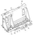
図3は、印刷ヘッドユニット60の具体的な構成と、インクの吐出原理を示す説明図である。図3に示すように、印刷ヘッドユニット60は、略L字形状をしており、図示しない黒インク用カートリッジとカラーインク用カートリッジとを搭載可能であって、両カートリッジを装着可能に仕切る仕切板31を備えている。
FIG. 3 is an explanatory diagram showing a specific configuration of the
印刷ヘッドユニット60の上端面には、印刷ヘッドユニット60の特性に応じて予め割り当てられたヘッド識別情報(「ヘッドID」とも呼ぶ)を示すヘッドIDシール100が貼りつけられている。このヘッドIDシール100に表示されたヘッドIDの内容については後述する。
A
なお、印刷ヘッド28とインクカートリッジの搭載部とを含む図3の構成全体を「印刷ヘッドユニット60」と呼ぶのは、この印刷ヘッドユニット60が1つの部品としてプリンタ20に着脱されるからである。すなわち、印刷ヘッド28を交換しようとする際には、印刷ヘッドユニット60を交換することになる。
The entire configuration of FIG. 3 including the
印刷ヘッドユニット60の底部には、印刷ヘッド28にインク容器からのインクを導く導入管71〜76が立設されている。印刷ヘッドユニット60に黒インク用のカートリッジおよびカラーインク用カートリッジを上方から装着すると、各カートリッジに設けられた接続孔に導入管71〜76が挿入される。
At the bottom of the
図4は、インクが吐出される機構を説明する説明図である。インク用カートリッジが印刷ヘッドユニット60に装着されると、インク用カートリッジ内のインクが導入管71〜76を介して吸い出され、図4に示したように、印刷ヘッドユニット60下部に設けられた印刷ヘッド28に導かれる。
FIG. 4 is an explanatory diagram for explaining a mechanism for ejecting ink. When the ink cartridge is attached to the
印刷ヘッド28は、各色毎に一列に設けられた複数のノズルnと、各ノズルnに設けられたピエゾ素子PEを動作させるアクチュエータ回路90と、を有している。アクチュエータ回路90は、ヘッド駆動回路52(図2)の一部であり、ヘッド駆動回路52内の図示しない駆動信号生成回路から与えられた駆動信号をオン/オフ制御する。すなわち、アクチュエータ回路90は、コンピュータ88から供給された印刷信号PSに従って、各ノズルに関してオン(インクを吐出する)またはオフ(インクを吐出しない)を示すデータをラッチし、オンのノズルについてのみ、駆動信号をピエゾ素子PEに印加する。
The
図5は、ピエゾ素子PEによるノズルnの駆動原理を示す説明図である。ピエゾ素子PEは、ノズルnまでインクを導くインク通路80に接する位置に設置されている。本実施例では、ピエゾ素子PEの両端に設けられた電極間に所定時間幅の電圧を印加することにより、図5(B)に示すように、ピエゾ素子PEが急速に伸張し、インク通路80の一側壁を変形させる。この結果、インク通路80の体積は、ピエゾ素子PEの伸張に応じて収縮し、この収縮分に相当するインクが、粒子Ipとなって、ノズルnの先端から高速に吐出される。このインク粒子Ipがプラテン26に装着された用紙Pに染み込むことにより、印刷が行なわれることになる。
FIG. 5 is an explanatory diagram showing the principle of driving the nozzle n by the piezo element PE. The piezo element PE is installed at a position in contact with the
図6は、印刷ヘッド28に設けられた複数列のノズルと複数のアクチュエータチップとの対応関係を示す説明図である。このプリンタ20は、ブラック(K)、濃シアン(C)、淡シアン(LC)、濃マゼンタ(M)、淡マゼンタ(LC)、イエロー(Y)の6色のインクを用いて印刷を行う印刷装置であり、各インク用のノズル列をそれぞれ備えている。なお、濃シアンと淡シアンとは、ほぼ同じ色相を有し、濃度が異なるシアンインクである。濃マゼンタインクと淡マゼンタインクも同様である。
FIG. 6 is an explanatory diagram showing a correspondence relationship between a plurality of nozzles provided in the
アクチュエータ回路90には、ブラックノズル列Kと濃シアンノズル列Cを駆動する第1のアクチュエータチップ91と、淡シアンノズル列LCと濃マゼンタノズル列Mを駆動する第2のアクチュエータチップ92と、淡マゼンタノズル列LMとイエローノズル列Yを駆動する第3のアクチュエータチップ93とが設けられている。
The
図7は、アクチュエータ回路90の分解斜視図である。3つのアクチュエータチップ91〜93は、ノズルプレート110とリザーバプレート112の積層体の上に接着剤で接着されている。また、アクチュエータチップ91〜93の上には、接続端子プレート120が固定される。接続端子プレート120の一端には、外部回路(具体的には図2のI/F専用回路50)との電気的接続のための外部接続端子124が形成されている。また、接続端子プレート120の下面には、アクチュエータチップ91〜93との電気的接続のための内部接続端子122が設けられている。さらに、接続端子プレート120の上には、ドライバIC126が設けられている。ドライバIC126内には、コンピュータ88から与えられた印刷信号をラッチする回路や、その印刷信号に応じて駆動信号をオン/オフするアナログスイッチなどが設けられている。なお、ドライバIC126と接続端子122,124との間の配線は図示が省略されている。
FIG. 7 is an exploded perspective view of the
図8は、アクチュエータ回路90の部分断面図である。ここでは、第1のアクチュエータチップ91と、その上部の接続端子プレート120の断面のみを示しているが、他のアクチュエータチップ92,93も第1のアクチュエータチップ91と同じ構造を有している。
FIG. 8 is a partial cross-sectional view of the
ノズルプレート110には、各インク用のノズル口が形成されている。リザーバプレート112は、インクの貯蔵部(リザーバ)を形成するための板状体である。アクチュエータチップ91は、インク通路80(図5)を形成するセラミック焼結体130と、その上方に壁面を介して配置されたピエゾ素子PEと、端子電極132とを有している。接続端子プレート120がアクチュエータチップ91の上に固定されると、接続端子プレート120の下面に設けられた接続端子122と、アクチュエータチップ91の上面に設けられている端子電極132とが電気的に接続される。なお、端子電極132とピエゾ素子PEとの間の配線は図示が省略されている。
In the
B.ノズル列間の記録位置ズレの発生:
後述する第1、第2実施例では、双方向印刷時にノズル列間に発生する記録位置ズレを調整している。そこで、これらの実施例を説明する前に、以下ではまず、ノズル列間の記録位置のズレの発生について説明する。
B. Occurrence of misregistration between nozzle rows:
In the first and second embodiments, which will be described later, a recording position shift that occurs between nozzle rows during bidirectional printing is adjusted. Therefore, before describing these embodiments, first, the occurrence of a shift in the recording position between the nozzle rows will be described.
図9は、異なるノズル列に関する双方向印刷時の位置ズレを示す説明図である。ノズルnは、印刷用紙Pの上方において双方向に水平に移動しており、往路と復路においてそれぞれインクを吐出することによって印刷用紙P上にドットを形成する。ここでは、ブラックインクKが吐出される場合と、シアンインクCが吐出される場合とを重ねて図示している。ブラックインクKは、鉛直下方に向けて吐出速度VK で吐出されるものと仮定し、一方、シアンインクCはブラックインクよりも低い吐出速度VC で吐出されるものと仮定している。各インクの合成速度ベクトルCVK ,CVC は、下方への吐出速度ベクトルと、ノズルnの主走査速度ベクトルVsとを合成したものとなる。ブラックインクKとシアンインクCでは、下方への吐出速度VK ,VC が異なるので、その合成速度CVK ,CVC の大きさや方向が互いに異なる。 FIG. 9 is an explanatory diagram showing positional misalignment during bidirectional printing regarding different nozzle arrays. The nozzle n moves horizontally in both directions above the printing paper P, and forms dots on the printing paper P by ejecting ink in the forward path and the backward path, respectively. Here, the case where the black ink K is ejected and the case where the cyan ink C is ejected are shown in an overlapping manner. The black ink K is assumed to be ejected vertically downward at the ejection speed V K , while the cyan ink C is assumed to be ejected at a lower ejection speed V C than the black ink. The combined velocity vectors CV K and CV C for each ink are a combination of the downward discharge velocity vector and the main scanning velocity vector Vs of the nozzle n. Since the black ink K and the cyan ink C have different downward discharge speeds V K and V C , the combined speeds CV K and CV C have different sizes and directions.
この例では、ブラックドットに関しては、双方向印刷の位置ズレがゼロになるように補正されている。しかし、シアンインクCの合成速度ベクトルCVC はブラックインクKの合成速度ベクトルCVK とは異なるので、ブラックインクKと同じタイミングでシアンインクCを吐出すると、シアンドットの記録位置に関しては印刷用紙P上で大きなズレが生じてしまう。また、往路におけるブラックドットとシアンドットの相対的な位置関係(左右の関係)は、復路における位置関係とは逆転していることが解る。 In this example, black dots are corrected so that the misalignment in bidirectional printing becomes zero. However, since the combined velocity vector CV C of cyan ink C is different from the synthetic speed vector CV K of black ink K, when ejecting the cyan ink C at the same timing as the black ink K, the printing paper P with respect to the recording position of the cyan dots A large deviation will occur on the top. It can also be seen that the relative positional relationship (left-right relationship) between the black dots and cyan dots in the forward path is opposite to that in the backward path.
図10は、図9に示されている記録位置のズレを平面的に示す説明図である。ここでは、ブラックインクKとシアンインクCとを用いて、副走査方向yに沿った縦罫線が往路と復路でそれぞれ記録された場合が示されている。ブラックインクを用いて往路で記録された縦罫線は、主走査方向xの位置が復路で記録された縦罫線と一致している。一方、シアンインクを用いて往路で記録された縦罫線はブラックの縦罫線よりも右側に記録され、復路で記録された縦罫線はブラックの縦罫線よりも左側に記録されている。 FIG. 10 is an explanatory diagram showing a plan shift of the recording position shown in FIG. Here, a case is shown where vertical ruled lines along the sub-scanning direction y are recorded in the forward path and the backward path using the black ink K and the cyan ink C, respectively. The vertical ruled lines recorded on the forward path using black ink coincide with the vertical ruled lines recorded on the return path in the main scanning direction x. On the other hand, the vertical ruled line recorded in the forward path using cyan ink is recorded on the right side of the black vertical ruled line, and the vertical ruled line recorded in the return path is recorded on the left side of the black vertical ruled line.
このように、ブラックノズル列に関してのみ往路と復路の記録位置のズレを補正したときには、他のノズル列に関しては記録位置のズレをうまく補正できない場合があった。 As described above, when the misalignment between the print positions of the forward pass and the return pass is corrected only for the black nozzle row, the misalignment of the print position may not be corrected well for the other nozzle rows.
各ノズル列から吐出されるインク滴の吐出速度は、以下のような種々の要因に依存して変化する。
(1)アクチュエータチップの製造誤差。
(2)インクの物理的性質(例えば粘度)。
(3)インク滴の重量。
The ejection speed of ink droplets ejected from each nozzle row varies depending on various factors as described below.
(1) Manufacturing error of the actuator chip.
(2) Physical properties of the ink (for example, viscosity).
(3) Weight of ink droplet.
インク滴の吐出速度の主要な要因がアクチュエータチップの製造誤差である場合には、同じアクチュエータチップから吐出されるインク滴の吐出速度はほぼ同じである。従って、この場合には、異なるアクチュエータチップで駆動されるノズル列のグループ毎に、主走査方向における記録位置のズレを補正することが好ましい。 When the main factor of the ink droplet ejection speed is an actuator chip manufacturing error, the ink droplet ejection speed ejected from the same actuator chip is substantially the same. Therefore, in this case, it is preferable to correct the recording position shift in the main scanning direction for each group of nozzle rows driven by different actuator chips.
一方、インクの物理的性質やインク滴の重量もその吐出速度に大きな影響がある場合には、インク毎に、あるいは、ノズル列毎に、主走査方向におけるドットの記録位置のズレを補正することが好ましい。 On the other hand, if the physical properties of the ink and the weight of the ink droplets have a large effect on the ejection speed, the dot recording position deviation in the main scanning direction should be corrected for each ink or for each nozzle row. Is preferred.
C.第1実施例(ノズル列間の記録位置ズレ補正1):
図11は、本発明の第1実施例における処理の全体を示すフローチャートである。ステップS1では、製造ラインにおいてプリンタ20が組み立てられ、ステップS2では、作業者によって相対補正値がプリンタ20内に設定される。ステップS3ではプリンタ20が工場から出荷され、ステップS4では、プリンタ20を購入したユーザが、使用時の位置ズレを補正するための基準補正値を設定して、印刷を実行する。以下ではステップS2,S4の内容をそれぞれ詳細に説明する。
C. First Example (Recording
FIG. 11 is a flowchart showing the entire processing in the first embodiment of the present invention. In step S1, the
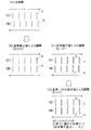
図12は、図10のステップS2の詳細手順を示すフローチャートである。ステップS11では、プリンタ20を用いて相対補正値決定用のテストパターン(相対位置ズレ検査用パターン)を印刷する。図13は、相対補正値決定用のテストパターンの一例を示す説明図である。このテストパターンは、印刷用紙Pの上に、副走査方向yに伸びる6本の縦罫線LK ,LC ,LLC,LM ,LLM,LY が6色のインクK,C,LC,M,LM,Yでそれぞれ形成されたものである。なお、これらの6本の縦罫線は、一定の速度でキャリッジ30を走査しながら、6組のノズル列から同時にインクを吐出させることによって記録されている。なお、1回の主走査でのインク吐出では、副走査方向yのノズルピッチだけ離れたドットを形成できるだけなので、図13に示すような縦罫線を記録するためには、複数回の主走査時において同じタイミングでインクを吐出する。
FIG. 12 is a flowchart showing the detailed procedure of step S2 of FIG. In step S11, the
なお、テストパターンとしては、縦罫線では無く、間欠的にドットが記録されたような直線状のパターンを使用することも可能である。これは、後述する基準補正値決定用のテストパターンについても同様である。 As the test pattern, a linear pattern in which dots are intermittently recorded can be used instead of the vertical ruled line. The same applies to a test pattern for determining a reference correction value described later.
図12のステップS12では、図13に示す6本の縦罫線の相互のズレ量を測定する。この測定は、例えば、テストパターンの画像をCCDカメラで読取り、縦罫線LK ,LC ,LLC,LM ,LLM,LY の主走査方向xの位置を画像処理によって測定することによって実現される。6本の縦罫線の位置は、6組のノズル列からインクを同時に吐出することによって形成されているので、仮に6組のノズル列によるインクの吐出速度が同一であれば、6本の縦罫線の間隔はノズル列の間隔に等しいはずである。 In step S12 of FIG. 12, the mutual shift amount of the six vertical ruled lines shown in FIG. 13 is measured. This measurement is performed, for example, by reading an image of a test pattern with a CCD camera and measuring the positions of the vertical ruled lines L K , L C , L LC , L M , L LM , and L Y in the main scanning direction by image processing. Realized. The positions of the six vertical ruled lines are formed by simultaneously ejecting ink from the six sets of nozzle rows. Therefore, if the ink discharge speeds by the six sets of nozzle rows are the same, the six vertical ruled lines are set. The spacing of should be equal to the spacing of the nozzle rows.
図13に示すx座標値xK ,xC ,xLC,xM ,xLM,xY は、ブラックインクの縦罫線LK のx座標値xK を基準としたときに、他の5本の縦罫線がノズル列の間隔の設計値通りに並んでいる場合のそれぞれの縦罫線の座標値を示している。そこで、これらのx座標値xK ,xC ,xLC,xM ,xLM,xY で示される位置を、以下では「設計位置」とも呼ぶ。ステップS12では、ブラックの縦罫線以外の5本の縦罫線について、設計位置と実際の縦罫線位置とのズレ量δC ,δLC,δM ,δLM,δY を測定する。このとき、設計位置よりも右側にずれている場合にはズレ量δをプラスの値とし、設計位置よりも左側にずれている場合にはズレ量δをマイナスの値とする。 X-coordinate value x K shown in FIG. 13, x C, x LC, x M, x LM, x Y is the x-coordinate value x K of vertical ruled lines L K of the black ink when the reference, the other five The coordinate values of the respective vertical ruled lines when the vertical ruled lines are arranged according to the design value of the interval between the nozzle rows are shown. Therefore, the positions indicated by these x coordinate values x K , x C , x LC , x M , x LM , and x Y are also referred to as “design positions” below. In step S12, deviation amounts δ C , δ LC , δ M , δ LM , δ Y between the design position and the actual vertical ruled line position are measured for five vertical ruled lines other than the black vertical ruled line. At this time, when the position is shifted to the right side from the design position, the shift amount δ is set to a positive value. When the position is shifted to the left side from the design position, the shift amount δ is set to a negative value.
ステップS13では、こうして測定されたズレ量から、適切なヘッドIDを作業者が決定し、プリンタ20内にそのヘッドIDを設定する。このヘッドIDは、測定されたズレ量を補正するための適切な相対補正値を示す情報である。適切な相対補正値Δとしては、例えば、以下の(1)式で与えられるように、基準となる縦罫線LK 以外の他のすべての縦罫線のズレ量の平均値δave の正負の符号を反転したものを用いることができる。
Δ=−δave =−Σδi /(N−1) …(1)
ここで、Σは基準となるブラックインクの縦罫線以外のすべての縦罫線のズレ量δiの和を取る演算を示しており、Nは縦罫線の総数(すなわちノズル列の数)を示している。
In step S <b> 13, the operator determines an appropriate head ID from the amount of deviation thus measured, and sets the head ID in the
Δ = −δave = −Σδi / (N−1) (1)
Here, Σ represents an operation for taking the sum of the deviation amounts δi of all vertical ruled lines other than the black ruled vertical ruled line, and N represents the total number of vertical ruled lines (that is, the number of nozzle rows). .
図14は、相対補正値ΔとヘッドIDとの関係を示す説明図である。この例では、相対補正値Δが−35.0μmのときにはヘッドIDが1に設定され、相対補正値Δが17.5μm増加するたびにヘッドIDの値が1つ増加する。ここで、17.5μmは、プリンタ20において調整可能な主走査方向のズレ量の最小値(最小調整可能値)である。この最小調整可能値としては、主走査方向に沿ったドットピッチに等しい値を使用することができる。例えば、主走査方向の解像度が1440dpiのときには、そのドットピッチは約17.5μm(=25.4mm/1440)であり、この値が最小調整可能値として使用される。なお、ドットピッチよりも小さな値を最小調整可能値とすることも可能である。
FIG. 14 is an explanatory diagram showing the relationship between the relative correction value Δ and the head ID. In this example, the head ID is set to 1 when the relative correction value Δ is −35.0 μm, and the value of the head ID increases by one every time the relative correction value Δ increases by 17.5 μm. Here, 17.5 μm is the minimum value (minimum adjustable value) of the shift amount in the main scanning direction that can be adjusted in the
こうして決定されたヘッドIDは、プリンタ20内のPROM43(図2)の中に格納される。本実施例では、さらに、印刷ヘッドユニット60(図3)の上面に、ヘッドIDを示すヘッドIDシール100が貼り付けられる。あるいは、印刷ヘッドユニット60に設けられているドライバIC126(図7)内に不揮発性メモリ(例えばプログラマブルROM)を設けておき、その不揮発性メモリの中にヘッドIDを格納するようにしてもよい。印刷ヘッドユニット60にヘッドIDシール100を貼りつけたり、印刷ヘッドユニット60内の不揮発性メモリにヘッドIDを格納したりしておけば、印刷ヘッドユニット60を他のプリンタ20に使用する場合にも、その印刷ヘッドユニット60に適したヘッドIDを利用することができるという利点がある。
The head ID thus determined is stored in the PROM 43 (FIG. 2) in the
なお、ステップS2における相対補正値の決定は、印刷ヘッドユニット60をプリンタ20に組み込む前の工程において、専用の検査装置に印刷ヘッドユニット60を組み込んだ状態で実行することも可能である。この場合には、その後のプリンタ組み立て工程において、印刷ヘッドユニット60をプリンタ20に組み込む際に、ヘッドIDがプリンタ20内のPROM43に登録される。PROM43内への登録の方法としては、例えば、ヘッドIDシール100を専用の読み取り装置で読取る方法や、作業者がヘッドIDをキーボードから入力する方法を採用することができる。あるいは、印刷ヘッドユニット60内の不揮発性メモリに格納されたヘッドIDを、プリンタ20内のPROM43に転送するようにしてもよい。
The determination of the relative correction value in step S2 can also be executed in a state in which the
なお、相対補正値Δは、以下の(2)式で与えられるように、淡シアンと淡マゼンタのズレ量の平均値としてもよい。
Δ=−(δLC+δLM)/2 …(2)
The relative correction value Δ may be an average value of the deviation amounts of light cyan and light magenta, as given by the following equation (2).
Δ = − (δ LC + δ LM ) / 2 (2)
淡シアンと淡マゼンタは、カラー画像の中間調領域(特にシアンやマゼンタの画像濃度が約10%〜約30%の範囲)において最も多く用いられるインクであり、これらのインクのドットの記録位置の精度が画質に大きな影響を有している。従って、淡シアンと淡マゼンタのズレ量の平均値からヘッドIDを決定するようにすれば、これらの位置ズレ量を低減できるので、カラー画像の画質を向上させることが可能である。 Light cyan and light magenta are inks that are most frequently used in a halftone area of a color image (particularly, the image density of cyan or magenta is in the range of about 10% to about 30%). Accuracy has a significant effect on image quality. Therefore, if the head ID is determined from the average value of the shift amounts of light cyan and light magenta, these positional shift amounts can be reduced, so that the image quality of the color image can be improved.
なお、上記(2)式を用いる場合には、淡シアンインクと淡マゼンタインクについてのみ、ブラックインクからのズレ量δを測定すれば十分である。 Note that when the above equation (2) is used, it is sufficient to measure the deviation amount δ from the black ink only for the light cyan ink and the light magenta ink.
図11のフローチャートに示したように、プリンタ20内にヘッドIDが設定された後にプリンタ20が出荷される。ユーザがプリンタ20を使用する際には、このヘッドIDを用いて双方向印刷時の記録位置のズレが以下のように調整される。
As shown in the flowchart of FIG. 11, the
図15は、ユーザの使用時におけるズレ調整の手順を示すフローチャートである。ステップS21では、プリンタ20を用いて基準補正値決定用のテストパターン(基準位置ズレ検査用パターン)を印刷する。図16は、基準補正値決定用のテストパターンの一例を示す説明図である。このテストパターンは、ブラックインクを用いて往路と復路でそれぞれ印刷された複数の縦罫線で構成されている。往路では一定の間隔で縦罫線を記録しているが、復路では、縦罫線の主走査方向の位置を1ドットピッチ単位で順次ずらしている。この結果、印刷用紙P上には、往路の縦罫線と復路の縦罫線との相対位置が1ドットピッチずつずれていくような複数組の縦罫線対が印刷される。複数組の縦罫線対の下には、ズレ調整番号の数字が印刷される。ズレ調整番号は、好ましい補正状態を示す補正情報としての機能を有する。ここで、「好ましい補正状態」とは、往路または復路における記録位置(または記録タイミング)を適切な基準補正値で補正したときに、往路と復路でそれぞれ形成されたドットの主走査方向の位置が一致するような状態を言う。従って、好ましい補正状態は、適切な基準補正値によって実現される。なお、図16の例では、ズレ調整番号が4である縦罫線対が、好ましい補正状態を示している。
FIG. 15 is a flowchart showing a procedure for adjusting the deviation during use by the user. In step S21, a test pattern for determining a reference correction value (reference position deviation inspection pattern) is printed using the
なお、基準補正値決定用のテストパターンは、相対補正値の決定の際に使用されていた基準ノズル列で形成される。従って、相対補正値の決定の際に、ブラックノズル列の代わりにマゼンタノズル列が基準ノズル列として使用された場合には、基準補正値決定用のテストパターンも、そのマゼンタノズル列で形成される。 Note that the test pattern for determining the reference correction value is formed by the reference nozzle row used when determining the relative correction value. Therefore, when the magenta nozzle row is used as the reference nozzle row in place of the black nozzle row when determining the relative correction value, the test pattern for determining the reference correction value is also formed by the magenta nozzle row. .
ユーザは、このテストパターンを観察して、最もズレの少ない縦罫線対のズレ調整番号を、コンピュータ88(図2)のプリンタドライバのユーザインタフェイス画面(図示せず)に入力する。このズレ調整番号は、プリンタ20内のPROM43に格納される。
The user observes this test pattern and inputs the shift adjustment number of the vertical ruled line pair with the least shift on the user interface screen (not shown) of the printer driver of the computer 88 (FIG. 2). The deviation adjustment number is stored in the
その後、ステップS23においてユーザによって印刷の実行が指示されると、ステップS24において、基準補正値と相対補正値とを用いたズレ補正を行いながら双方向印刷が実行される。図17は、第1実施例における双方向印刷時のズレ補正に関連する主要な構成を示すブロック図である。プリンタ20内のPROM43には、ヘッドID格納領域200と、調整番号格納領域202と、相対補正値テーブル204と、基準補正値テーブル206とが設けられている。ヘッドID格納領域200には、好ましい相対補正値を示すヘッドIDが格納されている。調整番号格納領域202には、好ましい基準補正値を示すズレ調整番号が格納されている。相対補正値テーブル204は、図14に示したヘッドIDと相対補正値Δとの関係を格納したテーブルである。基準補正値テーブル206は、ズレ調整番号と、基準補正値の関係を示すテーブルである。基準補正値テーブル206は、図16に示したテストパターンにおける復路の縦罫線の記録位置のズレ量(すなわち基準補正値)とズレ調整番号との関係を格納したテーブルである。
Thereafter, when the execution of printing is instructed by the user in step S23, bidirectional printing is executed in step S24 while performing misalignment correction using the reference correction value and the relative correction value. FIG. 17 is a block diagram illustrating a main configuration related to misalignment correction during bidirectional printing in the first embodiment. The
プリンタ20内のRAM44には、双方向印刷時の位置ズレを補正するための位置ズレ補正実行部(調整値決定部)210としての機能を有するコンピュータプログラムが格納されている。位置ズレ補正実行部210は、PROM43に格納されているヘッドIDに対応する相対補正値を相対補正値テーブル204から読み出すとともに、ズレ調整番号に対応する基準補正値を基準補正値テーブル206から読み出す。位置ズレ補正実行部210は、復路において位置センサ39(図1)からキャリッジ30の原点位置を示す信号を受け取ると、相対補正値と基準補正値との総合的な補正値に応じて、ヘッドの記録タイミングを指示するための信号(遅延量設定値ΔT)をヘッド駆動回路52に供給する。ヘッド駆動回路52内のは、3つのアクチュエータチップ91〜93に同一の駆動信号を供給しており、位置ズレ補正実行部210から与えられた記録タイミング(すなわち遅延量設定値ΔT)に応じて復路の記録位置を調整する。これによって、復路において、6組のノズル列の記録位置が共通する補正量で調整される。前述したように、相対補正値も基準補正値も、共に、主走査方向のドットピッチの整数倍に設定されているので、この記録位置(すなわち記録タイミング)も主走査方向のドットピッチの単位で調整される。なお、総合的な補正値は、基準補正値と相対補正値とを加算した値である。
The
図18は、基準補正値と相対補正値とを用いた位置ズレ補正の内容を示す説明図である。図18(A)は、位置ズレの調整を行っていない場合にブラックドットで形成された縦罫線が往路と復路でずれた位置に印刷されることを示している。図18(B)は、基準補正値を用いてブラックドットの位置ズレを調整した結果を示している。基準補正値による補正を行うと、ブラックドットに関しては、双方向印刷時に位置ズレが解消される。図18(C)は、図18(B)と同じ調整状態において、ブラックドットで形成された縦罫線の他に、シアンドットで形成された縦罫線も印刷した場合を示している。図18(C)は、図10と同じものであり、ブラックドットの位置ズレは無いが、シアンドットの位置ズレはかなり大きい。図18(D)は、基準補正値によるズレ調整に加えて、シアンドットに関する相対補正値Δ(=−δC )によるズレ調整も行った場合のブラックドットの罫線とシアンドットの罫線とを示している。図18(D)では、シアンドットの位置ズレは軽減されているが、ブラックドットの位置ズレはやや増加しており、この結果、ブラックドットとシアンドットの位置ズレがほぼ同程度に減少している。この理由は、復路における6組のノズル列の記録位置を、共通する補正量で補正しているからである。図18(D)の例は、ブラックドットとシアンドットとの2種類のドットが位置ズレ調整の対象ドットとして選択され、これらの2種類のドットに関する位置ズレ調整が行われた例である。 FIG. 18 is an explanatory diagram showing the contents of positional deviation correction using the reference correction value and the relative correction value. FIG. 18A shows that vertical ruled lines formed with black dots are printed at positions shifted in the forward path and the backward path when the positional deviation is not adjusted. FIG. 18B shows a result of adjusting the positional deviation of the black dots using the reference correction value. When the correction using the reference correction value is performed, the positional deviation of the black dots is eliminated during bidirectional printing. FIG. 18C shows a case where vertical ruled lines formed with cyan dots are printed in addition to the vertical ruled lines formed with black dots in the same adjustment state as in FIG. 18B. FIG. 18C is the same as FIG. 10 and there is no black dot misalignment, but the cyan dot misalignment is quite large. FIG. 18D shows a black dot ruled line and a cyan dot ruled line in the case where the shift adjustment by the relative correction value Δ (= −δ C ) for cyan dots is performed in addition to the shift adjustment by the reference correction value. ing. In FIG. 18D, the positional deviation of the cyan dots is reduced, but the positional deviation of the black dots is slightly increased. As a result, the positional deviation between the black dots and the cyan dots is reduced to approximately the same level. Yes. This is because the recording positions of the six nozzle rows in the return path are corrected with a common correction amount. The example of FIG. 18D is an example in which two types of dots, black dots and cyan dots, are selected as the target dots for positional deviation adjustment, and positional deviation adjustment for these two types of dots is performed.
図19は、シアンドットのみを位置ズレ調整の対象としたときの位置ズレ補正の内容を示す説明図である。図19(A)〜図19(C)に示す基準補正値による調整は図18(A)〜図18(C)と同じであり、図19(D)は図18(D)と異なる。図19(D)では、相対補正値Δとして、相対補正値決定用テストパターン(図13)におけるシアンドットのズレ量δC の2倍の値(正確には、それにマイナス符号を付した値)が使用されている。こうすれば、ブラックドットの位置ズレは大きくなるが、シアンドットは往復の位置ズレをほぼ0にすることが可能である。 FIG. 19 is an explanatory diagram showing the contents of positional deviation correction when only cyan dots are targeted for positional deviation adjustment. The adjustment by the reference correction value shown in FIGS. 19A to 19C is the same as that in FIGS. 18A to 18C, and FIG. 19D is different from FIG. In FIG. 19D, as the relative correction value Δ, a value twice the cyan dot shift amount δ C in the relative correction value determination test pattern (FIG. 13) (precisely, a value with a minus sign added thereto). Is used. By doing so, the positional deviation of the black dots becomes large, but the cyan dot can make the positional deviation of the reciprocation almost zero.
図18と図19の例から理解できるように、相対補正値決定用テストパターンにおける特定のドットのズレ量δそのものを相対補正値Δとして使用した場合には、その特定のドットと基準ドット(ブラックドット)との双方が位置ズレ調整の対象ドットに相当し、これらの対象ドットに関する位置ズレを減少させることができる。一方、相対補正値決定用テストパターンにおける特定のドットのズレ量δの2倍を相対補正値Δとして使用した場合には、その特定のドットのみが位置ズレ調整の対象ドットに相当し、その対象ドットに関する位置ズレを低減させることができる。具体的には、前述した(2)式で与えられる相対補正値Δ(=−(δLC+δLM)/2)を使用した場合にはは、ブラックドットと淡シアンドットと淡マゼンタドットの3種類のドットに関する位置ズレをほぼ同程度に低減できる。また、その2倍の値を相対補正値として使用した場合には、淡シアンドットと淡マゼンタドットの2種類のドットに関する位置ズレをほぼ同程度に低減できる。同様に、前述した(1)式で与えられる相対補正値Δ(=−δave )を使用した場合には、6種類のすべてのドットに関する位置ズレをほぼ同程度に低減できる。また、その2倍の値を相対補正値として使用した場合には、ブラックドット以外の5種類のドットに関する位置ズレをほぼ同程度に低減できる。 As can be understood from the examples of FIGS. 18 and 19, when the deviation amount δ of a specific dot in the relative correction value determination test pattern is used as the relative correction value Δ, the specific dot and the reference dot (black Both the dot and the dot correspond to the target dots for positional deviation adjustment, and the positional deviation regarding these target dots can be reduced. On the other hand, when twice the deviation amount δ of a specific dot in the relative correction value determination test pattern is used as the relative correction value Δ, only that specific dot corresponds to the target dot for positional deviation adjustment. It is possible to reduce the positional deviation regarding the dots. Specifically, when the relative correction value Δ (= − (δ LC + δ LM ) / 2) given by the above-described equation (2) is used, 3 of black dots, light cyan dots, and light magenta dots are used. It is possible to reduce the positional misalignment regarding the types of dots to almost the same extent. Further, when the double value is used as the relative correction value, the positional deviation regarding the two types of dots of the light cyan dot and the light magenta dot can be reduced to substantially the same level. Similarly, when the relative correction value Δ (= −δave) given by the above-described equation (1) is used, the positional deviation regarding all six types of dots can be reduced to substantially the same level. In addition, when the double value is used as the relative correction value, the positional deviation regarding the five types of dots other than the black dots can be reduced to substantially the same level.
なお、図18(D),図19(D)から解るように、基準補正値と相対補正値とに基づいて位置ズレ調整を行うと、カラーインクのドットの位置ズレが過度に大きくなることが防止されるので、カラー画像の画質が向上する。 As can be seen from FIGS. 18D and 19D, when the positional deviation adjustment is performed based on the reference correction value and the relative correction value, the positional deviation of the color ink dots may become excessively large. Therefore, the quality of the color image is improved.
なお、白黒印刷では、カラーインクを用いないので、図18(D)や図19(D)のような相対補正値を用いた位置ズレ補正を行う必要が無い。従って、白黒印刷では、図18(B)のように基準補正値のみを用いた位置ズレ補正の方が好ましい。そこで、プリンタ20の制御回路40(具体的には図17の位置ズレ補正実行部210)は、コンピュータ88(図1)から白黒印刷であることが通知されたときには、基準補正値のみを用いて双方向印刷時の位置ズレを補正し、また、カラー印刷であることが通知されたときには基準補正値と相対補正値とを用いて双方向印刷時の位置ズレを補正するように構成しておくことが好ましい。
In black-and-white printing, since color ink is not used, there is no need to perform positional deviation correction using relative correction values as shown in FIGS. 18D and 19D. Therefore, in black and white printing, positional deviation correction using only the reference correction value as shown in FIG. 18B is preferable. Therefore, when the
ところで、印刷ヘッドユニット60の経年劣化などの理由によって、印刷ヘッドユニット60を交換したい場合が生じる。印刷ヘッドユニット60を交換する場合には、交換後の印刷ヘッドユニット60のヘッドIDが、プリンタ20の制御回路40内のPROM43に書き込まれる。このヘッドIDの書き込みを実行する方法としては、次のようないくつかの方法がある。第1の方法は、印刷ヘッドユニット60に貼りつけられたヘッドIDシール100に表示されているヘッドIDを、ユーザがコンピュータ88から入力し、PROM43に書き込む方法である。第2の方法は、印刷ヘッドユニット60のドライバIC126(図7)内に設けられた不揮発性メモリから、制御回路40がヘッドIDを読み出してPROM43に書き込む方法である。このように、印刷ヘッドユニット60の交換後にそのヘッドIDをPROM43内に格納するようにすれば、交換後の印刷ヘッドユニット60に適したヘッドID(すなわち相対補正値)を用いて双方向印刷時の位置ズレを補正することが可能である。
By the way, there are cases where it is desired to replace the
以上のように、第1実施例では、ブラックノズル列を基準として他のノズル列に関する双方向印刷時の位置ズレを補正するための相対補正値を設定し、この相対補正値と、ブラックノズル列に関する基準補正値とに従ってカラー双方向印刷時の位置ズレを補正している。この結果、カラー印刷の画質を向上させることが可能である。特に、ユーザは、基準ノズル列に関する位置ズレの調整のみを行えばよく、すべてインクの位置ズレの調整を行わずにカラー双方向印刷時の画質を向上させることができるという利点がある。なお、白黒印刷の際に、基準補正値のみを用いて双方向印刷時の位置ズレを補正するようにすれば、白黒印刷も悪化させることが無いという利点がある。 As described above, in the first embodiment, the relative correction value for correcting the misalignment during bidirectional printing with respect to the other nozzle rows is set on the basis of the black nozzle row, and the relative correction value and the black nozzle row are set. The positional deviation at the time of color bi-directional printing is corrected according to the reference correction value. As a result, it is possible to improve the image quality of color printing. In particular, the user only needs to adjust the positional deviation with respect to the reference nozzle row, and there is an advantage that the image quality during color bidirectional printing can be improved without adjusting the positional deviation of all ink. It should be noted that, when monochrome printing is performed, the positional deviation during bidirectional printing is corrected using only the reference correction value, so that there is an advantage that monochrome printing is not deteriorated.
図20は、印刷ヘッド28のノズル列の他の構成を示す説明図である。この印刷ヘッド28aには、ブラック(K)の3組のノズル列K1〜K3が設けられており、また、シアン(C)、マゼンタ(M)、イエロー(Y)のノズル列がそれぞれ1組設けられている。白黒印刷の際には、3組のブラックノズル列K1〜K3をすべて用いて高速な印刷が実行される。一方、カラー印刷の際には、第1のアクチュエータチップ91の2組のブラックノズル列K1,K2は使用されず、第2のアクチュエータチップ92の1組のブラックノズル列K3と、シアンノズル列Cと、マゼンタノズル列Mと、イエローノズル列Yと、が用いられる。
FIG. 20 is an explanatory diagram illustrating another configuration of the nozzle row of the
このような印刷ヘッドを用いてカラー印刷を行う時には、例えば、以下の(3a)、(3b)式で与えられるように、シアンとマゼンタのズレ量の平均値、または、その2倍の値が、カラー双方向印刷時の相対補正値Δとして使用される。
Δ=−(δC +δM )/2 …(3a)
Δ=−(δC +δM ) …(3b)
When performing color printing using such a print head, for example, as given by the following equations (3a) and (3b), an average value of the deviation amount between cyan and magenta, or a value that is twice that value is obtained. , And used as a relative correction value Δ during color bidirectional printing.
Δ = − (δ C + δ M ) / 2 (3a)
Δ = − (δ C + δ M ) (3b)
なお、シアンとマゼンタのズレ量δC ,δM は、相対補正値決定用テストパターン(図13)において、カラー印刷の際に使用されるブラックノズル列K3で形成される縦罫線を基準として測定された相対的なズレ量である。 The deviation amounts δ C and δ M between cyan and magenta are measured with reference to the vertical ruled line formed by the black nozzle row K3 used for color printing in the relative correction value determination test pattern (FIG. 13). Relative amount of deviation.
このように、淡インクを用いない4色印刷の場合には、シアンとマゼンタのズレ量の平均値からヘッドIDを決定することによって、カラー画像の画質を向上させることが可能である。ここで、イエローを除外しているのは、イエロードットがあまり目立たず、イエロードットが双方向印刷時に多少ずれていても画質に大きな影響が無いためである。但し、シアンとマゼンタとイエローのズレ量の平均値からヘッドIDを決定するようにしてもよい。すなわち、カラー印刷に用いられる複数のノズル列の中で、基準ノズル列以外の他のすべてのノズル列に関するズレ量の平均値を用いて相対補正値を決定するようにしてもよい。 Thus, in the case of four-color printing that does not use light ink, it is possible to improve the image quality of a color image by determining the head ID from the average value of the amount of deviation between cyan and magenta. Here, yellow is excluded because the yellow dots are not so noticeable, and even if the yellow dots are slightly shifted during bidirectional printing, the image quality is not greatly affected. However, the head ID may be determined from the average value of the shift amounts of cyan, magenta, and yellow. That is, the relative correction value may be determined using the average value of the deviation amounts for all the nozzle rows other than the reference nozzle row among the plurality of nozzle rows used for color printing.
なお、基準とするブラックノズル列K3に対する他のブラックノズル列K1,K2の相対補正値ΔKを求めておくようにしてもよい。この相対補正値ΔKは、以下の(4)式に従って求めることができる。
ΔK=−(δK1 +δK2 )/2 …(4)
ここで、δK1 は第1のブラックノズル列K1に関するズレ量、δK2 は第2のブラックノズル列K2に関するズレ量である。
Note that the relative correction value ΔK of the other black nozzle rows K1, K2 with respect to the reference black nozzle row K3 may be obtained. This relative correction value ΔK can be obtained according to the following equation (4).
ΔK = − (δ K1 + δ K2 ) / 2 (4)
Here, δ K1 is a shift amount related to the first black nozzle row K1, and δ K2 is a shift amount related to the second black nozzle row K2.
白黒印刷の際に、この2組のブラックノズル列K1,K2に関する相対補正値ΔKと、基準とするブラックノズル列K3に関する基準補正値(図15で決定したもの)とを用いて双方向印刷時の位置ズレ補正すれば、3組のノズル列を用いた白黒印刷における双方向印刷の位置ズレを低減することができる。すなわち、白黒印刷の際に複数のブラックノズル列が用いられる場合には、その中の特定の基準ブラックノズル列に関する基準補正値と、他のブラックノズル列に関する相対補正値とを用いて双方向印刷時の位置ズレを補正するようにすることが好ましい。 At the time of monochrome printing, using the relative correction value ΔK for the two sets of black nozzle rows K1 and K2 and the reference correction value (determined in FIG. 15) for the black nozzle row K3 used as a reference, If the positional deviation correction is performed, it is possible to reduce the positional deviation of bidirectional printing in black and white printing using three sets of nozzle rows. That is, when a plurality of black nozzle arrays are used in black and white printing, bidirectional printing is performed using a reference correction value related to a specific reference black nozzle array and relative correction values related to other black nozzle arrays. It is preferable to correct the positional deviation of the hour.
D.第2実施例(ノズル列間の記録位置ズレ補正2):
図21は、第2実施例における双方向印刷時のズレ補正に関係する主要な構成を示すブロック図である。図17に示した構成との違いは、3つのアクチュエータチップ91,92,93を駆動するためのヘッド駆動回路52a,52b,52cが独立に設けられている点である。すなわち、3つのヘッド駆動回路52a,52b,52cは、3つのアクチュエータチップ91,92,93を独立に駆動する。このため、位置ズレ補正実行部210からの記録タイミングの指示も、各ヘッド駆動回路52a,52b,52cに対して独立に与えることができる。従って、双方向印刷時の位置ズレ補正も、アクチュエータチップ毎に実行することができる。
D. Second Embodiment (Recording
FIG. 21 is a block diagram showing a main configuration related to misalignment correction during bidirectional printing in the second embodiment. The difference from the configuration shown in FIG. 17 is that
第2実施例においても、第1のアクチュエータチップ91のブラックノズル列Kが基準ノズル列として使用される。従って、基準補正値は、第1実施例と同様に、ブラックノズル列Kを用いて記録されたテストパターンから決定される。
Also in the second embodiment, the black nozzle row K of the
一方、相対補正値は、第2実施例では各アクチュエータチップ毎に決定される。すなわち、第1のアクチュエータチップ91の相対補正値Δ91としては、以下の(4a)式で与えられるように、濃シアンノズル列Cで形成された縦罫線のズレ量δC の正負の符号を反転した値が採用される。
Δ91=−δC …(4a)
On the other hand, the relative correction value is determined for each actuator chip in the second embodiment. That is, as the relative correction value Δ 91 of the
Δ 91 = −δ C (4a)
また、第2と第3のアクチュエータチップ92,93の相対補正値Δ92,Δ93としては、以下の(4b)式および(4c)式でそれぞれ与えられるように、各アクチュエータチップのノズル列に関するズレ量の平均値の正負の符号を反転した値が採用される。
Δ92=−(δLC+δM )/2 …(4b)
Δ93=−(δLM+δY )/2 …(4c)
The relative correction values Δ 92 and Δ 93 of the second and third actuator chips 92 and 93 are related to the nozzle rows of the actuator chips as given by the following expressions (4b) and (4c), respectively. A value obtained by inverting the sign of the average value of the deviation amounts is adopted.
Δ 92 = − (δ LC + δ M ) / 2 (4b)
Δ 93 = − (δ LM + δ Y ) / 2 (4c)
なお、第2と第3のアクチュエータチップ92,93に対する相対補正値Δ92,Δ93は、1つのノズル列に関する基準ノズル列からの記録位置のズレ量から決定されていてもよい。このとき、上記(4b),(4c)の代わりに、例えば次の(5b),(5c)式を用いることができる。
Δ92=−δLC …(5b)
Δ93=−δLM …(5c)
Note that the relative correction values Δ 92 and Δ 93 for the second and third actuator chips 92 and 93 may be determined based on the shift amount of the recording position from the reference nozzle row for one nozzle row. At this time, instead of the above (4b) and (4c), for example, the following equations (5b) and (5c) can be used.
Δ 92 = −δ LC (5b)
Δ 93 = −δ LM (5c)
プリンタ20内のPROM43には、これらの3つの相対補正値Δ91,Δ92,Δ93を表すヘッドIDが格納される。また、位置ズレ補正実行部210には、このヘッドIDに応じて相対補正値Δ91,Δ92,Δ93が供給される。なお、上記(4a)式〜(5c)式の代わりに、これらの式の右辺の値の2倍の値を相対補正値として使用することも可能である。
The
上述した第2実施例では、アクチュエータチップ毎に相対補正値を独立に設定できる点に特徴がある。こうすれば、アクチュエータチップ毎に基準ノズル列からの相対的な位置ズレを補正できるので、双方向印刷時の位置ズレをより低減することができる。なお、1つのアクチュエータチップで3組のノズル列を駆動するタイプのプリンタでは、3組のノズル列毎に相対補正値を独立に設定することができる。 The second embodiment described above is characterized in that the relative correction value can be set independently for each actuator chip. In this way, the relative positional deviation from the reference nozzle row can be corrected for each actuator chip, so that the positional deviation during bidirectional printing can be further reduced. Note that in a printer of a type in which three sets of nozzle rows are driven by one actuator chip, the relative correction value can be set independently for each of the three sets of nozzle rows.
なお、中間調領域の画質を向上させる意味からは、ライトシアンドットやライトマゼンタドットを位置ズレ調整の対象ドットとして選択し、これらのドットの位置ズレを減少させることが好ましい。但し、上記第1および第2実施例の原理は、M種類(Mは2以上の整数)のインクを用いてカラー印刷を行う際に、M種類のインクのうちで比較的濃度の低い特定のインク(すなわち、ブラック以外の特定のインク)を位置ズレ調整の対象ドットとして選択し、その対象ドットの位置ズレを減少させる場合に適用可能である。 From the viewpoint of improving the image quality of the halftone area, it is preferable to select light cyan dots or light magenta dots as dots to be adjusted for positional deviation, and to reduce the positional deviation of these dots. However, the principle of the first and second embodiments described above is that when performing color printing using M types of ink (M is an integer of 2 or more), a specific density having a relatively low density among the M types of inks. This is applicable when ink (that is, a specific ink other than black) is selected as a target dot for positional deviation adjustment and the positional deviation of the target dot is reduced.
E.第3実施例(サイズの異なるドット間の記録位置ズレ補正):
上述した第1および第2実施例ではノズル列間の記録位置ズレを補正していたが、以下に説明する第3実施例では、大きさが異なる複数種類のドット間の記録位置ズレを補正する。
E. Third Example (Correction of recording position deviation between dots of different sizes):
In the first and second embodiments described above, the recording position deviation between the nozzle rows is corrected. In the third embodiment described below, the recording position deviation between a plurality of types of dots having different sizes is corrected. .
図22は、第3実施例においてヘッド駆動回路52(図2)から印刷ヘッド28に供給される原駆動信号ODRVの波形を示す説明図である。この原駆動信号ODRVでは、往路においては1画素区間の間に大ドット用波形W11と、小ドット用波形W12と、中ドット用波形W13とがこの順番に発生する。また、復路においては、1画素区間の間に中ドット用波形W21と、小ドット用波形W22と、大ドット用波形W23とがこの順番に発生する。往路においても、また、復路においても、3つの波形のいずれか1つを選択的に使用することによって、各画素位置に大ドットと小ドットと中ドットのいずれか1つを記録することができる。
FIG. 22 is an explanatory diagram showing the waveform of the original drive signal ODRV supplied from the head drive circuit 52 (FIG. 2) to the
往路と復路で大ドット用波形と中ドット用波形と小ドット用波形の発生の順番が異なっているのは、往路と復路における各ドットの主走査方向の記録位置をほぼ整合させるようにするためである。図23は、図22の原駆動信号ODRVを用いて形成される3種類のドットを示す説明図である。図23の格子は画素領域の境界を示しており、格子で区切られた1つの矩形領域が1画素分の領域に相当する。各画素領域内のドットは、印刷ヘッド28(図3)が主走査方向に沿って移動する際に、印刷ヘッド28によって吐出されるインク滴によって記録される。図23の例では、奇数番目のラスタラインL1、L3、L5は往路で記録され、偶数番目のラスタラインL2,L4は復路で記録される。この際、吐出されるインクの量を画素毎に調整することによって、サイズの異なる3種類のドットのいずれかを各画素位置に形成することができる。
The order of generation of the waveform for large dots, the waveform for medium dots, and the waveform for small dots in the forward path and the backward path is different in order to substantially match the recording positions of the dots in the main scanning direction in the forward path and the backward path. It is. FIG. 23 is an explanatory diagram showing three types of dots formed using the original drive signal ODRV of FIG. A grid in FIG. 23 indicates a boundary between pixel areas, and one rectangular area divided by the grid corresponds to an area for one pixel. The dots in each pixel area are recorded by ink droplets ejected by the
小ドットは、往路と復路の双方において1画素の領域のほぼ中央に形成される。また、中ドットは、1画素の領域の右寄りの位置に形成され、大ドットは1画素の領域のほぼ全体にわたって形成される。このように、図22(a),(b)に示した原駆動信号ODRVを用いることによって、往路と復路におけるインク滴の着弾位置をほぼ整合させることが可能である。もちろん、実際には各ドットに関して双方向印刷時に多少の位置ズレが発生する可能性があるので、その位置ズレ調整が必要である。 The small dot is formed at the approximate center of the area of one pixel in both the forward pass and the return pass. The medium dot is formed at a position on the right side of the one-pixel region, and the large dot is formed over almost the entire one-pixel region. As described above, by using the original drive signal ODRV shown in FIGS. 22A and 22B, it is possible to substantially match the landing positions of the ink droplets in the forward path and the backward path. Of course, in reality, there is a possibility that some misalignment may occur during bidirectional printing with respect to each dot, so that misalignment adjustment is necessary.
図24は、3種類のドットを用いた階調再現方法を示すグラフである。図24の横軸は画像信号レベルの相対値を示し、縦軸は3種類のドットのドット記録密度を示している。ここで、「ドット記録密度」とは、ドットが形成される画素位置の割合を意味している。例えば、100個の画素を含む領域内において、40個の画素位置にドットが形成される場合には、ドット記録密度は40%である。なお、画像信号レベルは、画像の濃度階調(濃度レベル)を示す階調値に相当する。 FIG. 24 is a graph showing a gradation reproduction method using three types of dots. The horizontal axis in FIG. 24 indicates the relative value of the image signal level, and the vertical axis indicates the dot recording density of three types of dots. Here, “dot recording density” means a ratio of pixel positions where dots are formed. For example, when dots are formed at 40 pixel positions in an area including 100 pixels, the dot recording density is 40%. The image signal level corresponds to a gradation value indicating the density gradation (density level) of the image.
図24のグラフにおいて、画像信号レベルが0%〜約16%の階調範囲では、小ドットのドット記録密度が画像信号レベルの増加とともに0%から約50%まで直線的に増加している。この結果、画像信号レベルが約16%である画像部分では小ドットが約半分のドット位置に形成される。また、画像信号レベルが約16%〜約50%の階調範囲では、小ドットのドット記録密度が画像信号レベルの増加とともに約50%から約15%まで直線的に減少しており、一方、中ドットのドット記録密度が0%から約80%まで直線的に増加している。画像信号レベルが約50%〜100%の階調範囲では、小ドットと中ドットのドット記録密度が画像信号レベルの増加とともに0%に至るまで直線的に減少しており、一方、大ドットのドット記録密度が0%から100%まで直線的に増加している。このように、各画像部分の画像信号レベルに応じて、その画像部分が1種類または2種類のドットで記録されることにより、画像の濃度階調が滑らかに直線的に再現される。 In the graph of FIG. 24, in the gradation range where the image signal level is 0% to about 16%, the dot recording density of small dots increases linearly from 0% to about 50% as the image signal level increases. As a result, in the image portion where the image signal level is about 16%, small dots are formed at about half the dot positions. In the gradation range where the image signal level is about 16% to about 50%, the dot recording density of small dots linearly decreases from about 50% to about 15% as the image signal level increases. The dot recording density of medium dots increases linearly from 0% to about 80%. In the gradation range where the image signal level is about 50% to 100%, the dot recording density of small dots and medium dots decreases linearly until reaching 0% as the image signal level increases. The dot recording density increases linearly from 0% to 100%. Thus, according to the image signal level of each image portion, the image portion is recorded with one or two types of dots, so that the density gradation of the image is smoothly and linearly reproduced.
往路と復路の記録位置のズレは、約50%以下の階調範囲(約10%〜約50%)である中間調領域において目立ち易い。特に、中間調領域において多く使用される中ドットや小ドットに関する往路と復路の記録位置のズレが、中間調領域の画像で目立ちやすい傾向にある。 The deviation in the recording position between the forward pass and the return pass is easily noticeable in a halftone area having a gradation range of about 50% or less (about 10% to about 50%). In particular, deviations in the recording positions of the forward and return passes for medium dots and small dots that are frequently used in the halftone area tend to be noticeable in the image in the halftone area.
ところで、双方向の記録位置ズレ調整用のテストパターンを中ドットや小ドットで作成すると、ユーザがテストパターンにおける位置ズレを認識し難いという問題が生じる。そこで、ユーザ調整時のテストパターンとしては、大ドットで形成したものを使用したい。第3実施例においては、これらの事情を考慮して、ユーザによる調整時には、大ドットで記録したテストパターンを用いて位置ズレの基準補正値を設定する。また、印刷実行時には、この基準補正値を、予め決定されていた相対補正値で補正することによって、小ドットまたは中ドットに関する記録位置ズレが減少するように位置ズレ調整を実行する。 By the way, when a test pattern for adjusting the bidirectional recording position deviation is created with medium dots and small dots, there arises a problem that it is difficult for the user to recognize the position deviation in the test pattern. Therefore, it is desirable to use a test pattern formed with large dots as a test pattern for user adjustment. In the third embodiment, in consideration of these circumstances, a reference deviation correction value for positional deviation is set using a test pattern recorded with large dots during adjustment by the user. Further, when printing is performed, this reference correction value is corrected with a predetermined relative correction value, so that the positional deviation adjustment is performed so that the recording positional deviation regarding small dots or medium dots is reduced.
第3実施例における処理手順は、前述した第1実施例において図11、図12および図15で説明したものと同じである。但し、相対補正値決定用のパターンは、第1実施例とは異なるものが使用される。 The processing procedure in the third embodiment is the same as that described in FIGS. 11, 12, and 15 in the first embodiment. However, the pattern for determining the relative correction value is different from that of the first embodiment.
図25は、相対補正値決定用のテストパターンの一例を示す説明図である。このテストパターンは、印刷用紙Pの上に形成されており、大ドット用テストパターンTPLと、小ドット用テストパターンTPSと、中ドット用テストパターンTPMとを含んでいる。3つのテストパターンTPL,TPS,TPMは、往路と復路とにおいてそれぞれ形成された1組の縦罫線対で構成されており、それぞれブラックインクを用いて記録されている。各縦罫線は、縦罫線の位置をなるべく正確に測定できるようにするために、それぞれ1ドット幅の直線とすることが好ましい。 FIG. 25 is an explanatory diagram showing an example of a test pattern for determining a relative correction value. This test pattern is formed on the printing paper P and includes a large dot test pattern TPL, a small dot test pattern TPS, and a medium dot test pattern TPM. The three test patterns TPL, TPS, and TPM are composed of a pair of vertical ruled lines formed on the forward path and the return path, respectively, and are recorded using black ink. Each vertical ruled line is preferably a straight line having a width of 1 dot so that the position of the vertical ruled line can be measured as accurately as possible.
第3実施例において、ステップS12(図12)では、図25に示す3つのテストパターンTPL,TPS,TPMにおける往路と復路の記録位置のズレ量δL,δS,δMをそれぞれ測定する。この測定は、例えば、テストパターンの画像をCCDカメラで読取り、3つのテストパターンの縦罫線対の主走査方向Xの位置を、画像処理によって測定することによって実現される。 In the third embodiment, in step S12 (FIG. 12), deviation amounts δL, δS, and δM of the recording positions of the forward path and the backward path in the three test patterns TPL, TPS, and TPM shown in FIG. 25 are measured. This measurement is realized, for example, by reading an image of a test pattern with a CCD camera and measuring the positions in the main scanning direction X of the vertical ruled line pairs of the three test patterns by image processing.
ステップS13では、こうして測定されたズレ量δL,δS,δMから、相対補正値が決定されて、プリンタ20内のPROMに設定される。相対補正値は、基準ドットに関するズレ量と、基準ドット以外のドットに関するズレ量との差分である。大ドットを基準ドットとしたときに、小ドットに関する相対補正値ΔSと、中ドットに関する相対補正値ΔMとは、それぞれ以下の(6a)式、(6b)式で与えられる。
ΔS=(δS−δL) …(6a)
ΔM=(δM−δL) …(6b)
In step S13, a relative correction value is determined from the deviations δL, δS, and δM thus measured, and set in the PROM in the
ΔS = (δS−δL) (6a)
ΔM = (δM−δL) (6b)
なお、相対補正値ΔS,ΔMの代わりに、テストパターンにおける3つのズレ量δL,δS,δMそのものを作業者がプリンタ20内のPROM43に設定してもよい。すなわち、プリンタ20内のPROMには、相対補正値を実質的に表す情報が設定されていればよい。また、プリンタ20内のPROM43に基準ドット以外のすべてのドットに関する相対補正値を設定する必要は無く、少なくとも1つの相対補正値(例えばΔS)が設定されていればよい。
Instead of the relative correction values ΔS, ΔM, the operator may set three deviation amounts δL, δS, δM in the test pattern in the
なお、各ドット用のテストパターンとしては、複数組の縦罫線対で構成されたものを使用してもよい。この場合には、各ドットに関する複数組の縦罫線対における往復の記録位置ズレ量の平均値を、そのドットに関する記録位置のズレ量として採用する。また、縦罫線の代わりに、間欠的にドットが記録されたような直線状のパターンを使用することも可能である。 As a test pattern for each dot, a pattern composed of a plurality of pairs of vertical ruled lines may be used. In this case, an average value of the reciprocal recording position deviations in a plurality of pairs of vertical ruled lines for each dot is adopted as the deviation of the recording position for that dot. Moreover, it is also possible to use a linear pattern in which dots are recorded intermittently instead of the vertical ruled lines.
さらに、テストパターンの一部をブラックインク以外の有彩色インク(マゼンタ、ライトマゼンタ、シアン、ライトシアンなど)で記録するようにしてもよい。また、この場合に、大ドット用テストパターンTPLをブラックインクで形成し、小ドット用テストパターンTPSと中ドット用テストパターンTPMを有彩色インクで形成するようにしてもよい。カラー画像では、有彩色インクの小ドットや中ドットが中間調領域の画質に大きな影響を与える。従って、小ドットや中ドットを有彩色インクで形成し、これらに対する相対補正値を設定するようにすれば、カラー画像の中間調領域の画質を向上させることができる。 Furthermore, a part of the test pattern may be recorded with chromatic ink (magenta, light magenta, cyan, light cyan, etc.) other than black ink. In this case, the large dot test pattern TPL may be formed of black ink, and the small dot test pattern TPS and the medium dot test pattern TPM may be formed of chromatic ink. In a color image, small dots and medium dots of chromatic ink have a great influence on the image quality in the halftone area. Therefore, if small dots and medium dots are formed with chromatic color ink and a relative correction value is set for these, the image quality of the halftone area of the color image can be improved.
第3実施例においては、図16に示した基準補正値決定用のテストパターン(基準位置ズレ検査用パターン)は、ブラックインクの大ドット(すなわち基準ドット)を用いて往路と復路でそれぞれ印刷された複数組の縦罫線対で構成されている。 In the third embodiment, the test pattern for determining the reference correction value (reference position shift inspection pattern) shown in FIG. 16 is printed on each of the forward pass and the return pass using large black ink dots (that is, reference dots). It consists of multiple pairs of vertical ruled lines.
なお、基準補正値決定用のテストパターンは、相対補正値の決定の際に使用されていた基準ドットを用いて形成される。従って、相対補正値の決定の際に、ブラックインクの大ドットの代わりにマゼンタインクの大ドットが基準ドットとして使用された場合には、基準補正値決定用のテストパターンも、そのマゼンタインクの大ドットで形成される。 Note that the test pattern for determining the reference correction value is formed using the reference dots used when determining the relative correction value. Therefore, when a large magenta ink dot is used as a reference dot instead of a black ink large dot when determining the relative correction value, the test pattern for determining the reference correction value also has a large magenta ink size. Formed with dots.
なお、ユーザによるズレ調整用のテストパターンを記録する際に用いる基準ドットとしては、最も大きなドットを選択することが好ましい。こうすれば、ユーザがテストパターンにおける位置ズレを認識し易いので、より正確に位置ズレ調整を行えるという利点がある。 Note that it is preferable to select the largest dot as the reference dot used when recording a test pattern for adjusting the deviation by the user. In this way, the user can easily recognize the positional deviation in the test pattern, so that there is an advantage that the positional deviation can be adjusted more accurately.
第3実施例においても、前述した図17または図21に示した構成によって位置ズレ調整が実行される。図26は、第3実施例における位置ズレ調整の内容を示す説明図である。図26(A)は、位置ズレの調整を行っていない場合に大ドット(基準ドット)で形成された縦罫線が、往路と復路でずれた位置に印刷されることを示している。図26(B)は、基準補正値を用いて大ドットの位置ズレを調整したと仮定したときの結果を示している。基準補正値による補正を行うと、大ドットに関しては、双方向印刷時に位置ズレが解消される。図26(C)は、図26(B)と同じ調整状態において、大ドットで形成された縦罫線の他に、小ドットで形成された縦罫線も印刷した場合を示している。図26(C)では、大ドットの位置ズレは解消されているが、小ドットの位置ズレは解消されていない。一方、カラー画像では、特に中間調領域における画質が重要であり、大ドットよりも小ドットに関する位置ズレの方が画質に対する影響が大きい。図26(D)では、基準補正値によるズレ調整に加えて、小ドット用相対補正値ΔSによるズレ調整も行った場合に大ドットで形成される縦罫線と小ドットで形成される縦罫線とを示している。図26(D)では、小ドットの位置ズレは減少しているが、大ドットの位置ズレはやや増加している。図26(D)から解るように、基準補正値と相対補正値とに基づいて位置ズレ調整を行うと、小ドットの位置ズレを小さくすることができるので、カラー画像の中間調領域の画質が向上する。 Also in the third embodiment, the positional deviation adjustment is executed by the configuration shown in FIG. 17 or FIG. FIG. 26 is an explanatory diagram showing the contents of the positional deviation adjustment in the third embodiment. FIG. 26A shows that vertical ruled lines formed with large dots (reference dots) are printed at positions shifted in the forward path and the backward path when the positional deviation is not adjusted. FIG. 26B shows the results when it is assumed that the positional deviation of the large dots has been adjusted using the reference correction value. When the correction using the reference correction value is performed, the positional deviation for large dots is eliminated during bidirectional printing. FIG. 26C shows a case where vertical ruled lines formed with small dots are printed in addition to the vertical ruled lines formed with large dots in the same adjustment state as FIG. In FIG. 26C, the positional deviation of the large dots has been eliminated, but the positional deviation of the small dots has not been eliminated. On the other hand, in a color image, the image quality is particularly important in a halftone area, and the positional deviation related to small dots has a greater influence on the image quality than large dots. In FIG. 26D, vertical ruled lines formed with large dots and vertical ruled lines formed with small dots when the shift adjustment with the small dot relative correction value ΔS is performed in addition to the shift adjustment with the reference correction value. Is shown. In FIG. 26D, the positional deviation of the small dots is reduced, but the positional deviation of the large dots is slightly increased. As can be seen from FIG. 26D, when the positional deviation adjustment is performed based on the reference correction value and the relative correction value, the positional deviation of the small dots can be reduced, so that the image quality of the halftone area of the color image is improved. improves.
なお、小ドットよりも中ドットの方が画質への影響が大きい場合には、中ドット用相対補正値ΔMを用いて位置ズレの調整を行うようにすればよい。また、小ドットと中ドットの画質への影響がほぼ同じ程度である場合には、小ドットと中ドットの相対補正値の平均値Δave を用いて、位置ズレの調整を行えばよい。この時、相対補正値の平均値Δave は、次の(7)式で与えられる。
Δave ={(δS−δL)+(δM−δL)}/2
={(δS+δM)/2}−δL …(7)
In the case where the influence of the medium dot on the image quality is larger than that of the small dot, the positional deviation may be adjusted using the medium dot relative correction value ΔM. When the influence on the image quality of the small dots and the medium dots is approximately the same, the positional deviation may be adjusted using the average value Δave of the relative correction values of the small dots and the medium dots. At this time, the average value Δave of the relative correction values is given by the following equation (7).
Δave = {(δS−δL) + (δM−δL)} / 2
= {(ΔS + δM) / 2} −δL (7)
(7)式から解るように、相対補正値の平均値Δave は、図25に示す小ドットおよび中ドットに関するズレ量δS,δMの平均値と、基準ドットに関するズレ量δLとの差分である。 As can be seen from the equation (7), the average value Δave of the relative correction values is a difference between the average value of the shift amounts δS and δM related to the small dots and the medium dots shown in FIG. 25 and the shift amount δL related to the reference dot.
この例からも理解できるように、相対補正値は、特定の大きさの1種類の対象ドットに関するものでなくてもよく、複数の対象ドットに関する平均的な相対補正値を用いることも可能である。なお、本明細書における「対象ドット」という用語は、「位置ズレ補正の対象となる1つ又は複数のドット」を意味している。なお、「対象ドット」の中に基準ドットが含まれるようにしてもよい。 As can be understood from this example, the relative correction value may not be related to one type of target dot having a specific size, and an average relative correction value related to a plurality of target dots may be used. . Note that the term “target dot” in this specification means “one or more dots to be subjected to positional deviation correction”. The reference dot may be included in the “target dot”.
ところで、白黒印刷では、むしろ大ドットの位置ズレの方が画質に対する影響が大きい場合がある。従って、白黒印刷では、図26(B)のように基準補正値のみを用いた位置ズレ補正の方が好ましいことがある。そこで、プリンタ20の制御回路40(具体的には図17の位置ズレ補正実行部210)は、コンピュータ88(図2)から白黒印刷であることが通知されたときには、基準補正値のみを用いて双方向印刷時の位置ズレを調整し、また、カラー印刷であることが通知されたときには基準補正値と相対補正値とを用いて双方向印刷時の位置ズレを調整するように構成しておくことが好ましい。
By the way, in black-and-white printing, the positional deviation of large dots may have a larger influence on image quality. Therefore, in black and white printing, it may be preferable to perform positional deviation correction using only the reference correction value as shown in FIG. Therefore, when the
また、白黒印刷でない場合にも、基準ドットの位置ズレが特に目立ちやすいときには、基準補正値をそのまま調整値として用いて位置ズレの調整を行うことが好ましい。すなわち、位置ズレ補正実行部(調整値決定部)210は、基準補正値を相対補正値で補正することによって調整値を決定する第1の調整モードと、基準補正値を調整値としてそのまま用いる第2の調整モードと、のいずれかに従って調整値を決定すればよい。 In addition, even in the case of non-monochrome printing, when the positional deviation of the reference dots is particularly noticeable, it is preferable to adjust the positional deviation using the reference correction value as an adjustment value as it is. That is, the positional deviation correction execution unit (adjustment value determination unit) 210 uses the first adjustment mode in which the adjustment value is determined by correcting the reference correction value with the relative correction value, and the reference correction value is used as the adjustment value as it is. The adjustment value may be determined according to one of the two adjustment modes.
以上のように、第3実施例では、大ドットに関する基準補正値を、予め準備された相対補正値で補正することによって小ドットや中ドットに関する位置ズレ調整用の調整値を決定しているので、中間調領域の画質を向上させることが可能である。特に、ユーザにおける位置ズレの調整時には、大ドットで形成されたテストパターンを用いるので、ユーザが位置ズレの調整を正確に行い易いという利点がある。 As described above, in the third embodiment, the reference correction value for the large dot is corrected with the relative correction value prepared in advance, so that the adjustment value for positional deviation adjustment for the small dot and the medium dot is determined. It is possible to improve the image quality of the halftone area. In particular, when adjusting the positional deviation for the user, the test pattern formed with large dots is used, so that there is an advantage that the user can easily adjust the positional deviation accurately.
F.変形例:
なお、この発明は上記の実施例や実施形態に限られるものではなく、その要旨を逸脱しない範囲において種々の態様において実施することが可能であり、例えば次のような変形も可能である。
F. Variations:
The present invention is not limited to the above-described examples and embodiments, and can be implemented in various modes without departing from the gist thereof. For example, the following modifications are possible.
F1.変形例1:
基準補正値と相対補正値とを用いて双方向印刷時の位置ズレを補正する際に、主走査速度(キャリッジの移動速度)として複数の値を利用可能なタイプのプリンタにおいては、ノズル列に関する相対補正値を主走査速度毎に設定することが好ましい。前述した図9の説明から解るように、主走査速度Vsが異なると、ノズル列同士の相対的な位置ズレ量も変化する。従って、異なる主走査速度毎に相対補正値を設定すれば、双方向印刷時の位置ズレをより低減することが可能である。
F1. Modification 1:
In a type of printer in which a plurality of values can be used as the main scanning speed (carriage moving speed) when correcting the positional deviation during bidirectional printing using the reference correction value and the relative correction value, it is related to the nozzle array. It is preferable to set a relative correction value for each main scanning speed. As can be seen from the description of FIG. 9 described above, when the main scanning speed Vs is different, the relative positional deviation amount between the nozzle rows also changes. Therefore, if the relative correction value is set for each different main scanning speed, it is possible to further reduce the positional deviation during bidirectional printing.
F2.変形例2:
基準補正値と相対補正値とを用いて双方向印刷時の位置ズレを補正する際に、同一のインクで複数の異なるサイズのドットを各画素位置に形成可能なタイプの多値プリンタにおいては、相対補正値をドットのサイズ毎に設定することが好ましい。ドットサイズが異なると、インク滴の吐出速度も変化する。従って、異なるドットサイズ毎に相対補正値を設定すれば、双方向印刷時の位置ズレをより低減することが可能である。なお、多値プリンタでは、1回の主走査の間は1つのノズル列によって同じサイズのドットしか形成できない場合がある。この場合には、各主走査毎に、ドットのサイズが選択されるので、位置ズレの補正に用いられる相対補正値も、各主走査毎にドットサイズに応じた適切な値が選択される。
F2. Modification 2:
In a multi-value printer of a type that can form a plurality of dots of different sizes with the same ink at each pixel position when correcting the positional deviation during bidirectional printing using the reference correction value and the relative correction value, It is preferable to set a relative correction value for each dot size. When the dot size is different, the ink droplet ejection speed also changes. Therefore, if a relative correction value is set for each different dot size, it is possible to further reduce the positional deviation during bidirectional printing. In a multi-value printer, only one dot of the same size may be formed by one nozzle row during one main scan. In this case, since the dot size is selected for each main scan, an appropriate value corresponding to the dot size is selected for each main scan as the relative correction value used for correcting the positional deviation.
なお、サイズの異なるドットを吐出する印刷動作は、インク吐出速度が互いに異なる印刷モードであると考えることができる。従って、上述した変形例は、インク吐出速度が互いに異なる複数のドット吐出モードのそれぞれに関してそれぞれ相対補正値を設定することを意味している。 Note that the printing operation for ejecting dots of different sizes can be considered as a printing mode in which the ink ejection speeds are different from each other. Therefore, the above-described modification means that a relative correction value is set for each of a plurality of dot ejection modes having different ink ejection speeds.
F3.変形例3:
第1および第2実施例では、基準ノズル列以外の各ノズル列毎に相対補正値を独立に設定することが好ましい。こうすれば、上述した第1、第2実施例よりもさらに位置ズレを低減することが可能である。また、同一のインクを吐出するノズル列のグループ毎に相対補正値を独立に設定するようにしてもよい。例えば、特定のインクを吐出するノズル列が2組設けられている場合には、その2組のノズルに対しては同一の相対補正値を適用するようにしてもよい。
F3. Modification 3:
In the first and second embodiments, it is preferable to set the relative correction value independently for each nozzle row other than the reference nozzle row. By doing so, it is possible to further reduce the positional deviation compared to the first and second embodiments described above. Alternatively, the relative correction value may be set independently for each group of nozzle rows that eject the same ink. For example, when two sets of nozzle rows for ejecting specific ink are provided, the same relative correction value may be applied to the two sets of nozzles.
F4.変形例4:
第1ないし第3実施例では、基準補正値と相対補正値を決定する際の基準ノズル列としてブラックノズル列を選択していたが、ブラックノズル列以外の任意のノズル列を基準ノズル列として選択することが可能である。但し、濃度の低いインク(淡シアンや淡マゼンタ)ではユーザが基準補正値を決定する際にテストパターンを認識しにくいため、濃度の比較的高いインク(ブラック、濃シアン、濃マゼンタ)を吐出するノズル列を基準ノズル列として用いることが好ましい。
F4. Modification 4:
In the first to third embodiments, the black nozzle row is selected as the reference nozzle row when determining the reference correction value and the relative correction value. However, any nozzle row other than the black nozzle row is selected as the reference nozzle row. Is possible. However, since ink with low density (light cyan or light magenta) cannot easily recognize the test pattern when the user determines the reference correction value, ink with relatively high density (black, dark cyan, dark magenta) is ejected. It is preferable to use the nozzle row as the reference nozzle row.
F5.変形例5:
第1ないし第3実施例では、ドットの記録位置(または記録タイミング)を調整することによって位置ズレを補正していたが、これ以外の手段を用いて位置ズレの補正を行うようにしてもよい。例えば、アクチュエータチップへの駆動信号を遅延させたり、駆動信号の周波数を調整したりすることによって、位置ズレの補正を行うようにすることも可能である。
F5. Modification 5:
In the first to third embodiments, the positional deviation is corrected by adjusting the dot recording position (or recording timing). However, other means may be used to correct the positional deviation. . For example, it is also possible to correct the positional deviation by delaying the drive signal to the actuator chip or adjusting the frequency of the drive signal.
F6.変形例6:
第3実施例では、1つのノズルで大きさの異なる3種類のドットを1画素領域内に記録できるものとしたが、この実施例の思想は、一般に、少なくとも1種類のインクについて、1つのノズルによって大きさの異なるN種類(Nは2以上の整数)のドットを各画素位置に記録し得るような印刷装置に適用可能である。この場合に、位置ズレの調整を行う対象ドットとしては、N種類のドットの中の最も大きなドット以外のドットを含む少なくとも1つドットを選択することができる。この対象ドットに関するズレの調整値が、N種類のドットに共通に適用される。
F6. Modification 6:
In the third embodiment, three types of dots having different sizes can be recorded in one pixel area with one nozzle. However, the idea of this embodiment is that one nozzle is generally used for at least one type of ink. Therefore, the present invention can be applied to a printing apparatus in which N types of dots (N is an integer of 2 or more) having different sizes can be recorded at each pixel position. In this case, at least one dot including dots other than the largest dot among the N types of dots can be selected as the target dot for adjusting the positional deviation. The adjustment value of the deviation regarding the target dot is commonly applied to N types of dots.
対象ドットとしては、例えば、N種類のドットの中の最小のドットや、N種類のドットの中の中程度の大きさを有するドットを選択することができる。このような対象ドットの選択によって、中間調領域における画質を向上できると期待される。 As the target dot, for example, the smallest dot among the N types of dots or the medium size dot among the N types of dots can be selected. It is expected that the image quality in the halftone area can be improved by selecting such target dots.
なお、「N種類の中の中程度の大きさを有するドット」とは、Nが奇数の場合には(N+1)/2番目の大きさを有するドットを意味し、Nが偶数の場合にはN/2番目または(N/2+1)番目の大きさを有するドットを意味する。この代わりに、中程度の大きさを有するドットとして、画像信号が50%の階調を示すときに最も数多く用いられるドットを用いてもよい。 Note that “N types of medium-sized dots” means a dot having (N + 1) / 2nd size when N is an odd number, and when N is an even number. It means a dot having an N / 2th or (N / 2 + 1) th size. Instead of this, as a dot having a medium size, the most frequently used dot may be used when the image signal shows 50% gradation.
F7.変形例7:
上記各実施例では、復路の記録位置(または記録タイミング)を調整することによって位置ズレを補正していたが、往路の記録位置を調整することによって位置ズレを補正するようにしてもよい。また、往路と復路の記録位置の両方を調整することによって位置ズレを補正するようにしてもよい。すなわち、一般には、往路と復路の記録位置の少なくとも一方を調整することによって位置ズレを補正するようにすればよい。
F7. Modification 7:
In each of the above embodiments, the positional deviation is corrected by adjusting the recording position (or recording timing) of the return path. However, the positional deviation may be corrected by adjusting the recording position of the forward path. Further, the positional deviation may be corrected by adjusting both the forward and backward recording positions. That is, in general, the positional deviation may be corrected by adjusting at least one of the recording positions of the forward path and the backward path.
F8.変形例8:
上記各実施例では、インクジェットプリンタについて説明したが、本発明はインクジェットプリンタに限らず、一般に、印刷ヘッドを用いて印刷を行う種々の印刷装置に適用可能である。また、本発明は、インク滴を吐出する方法や装置に限らず、他の手段でドットを記録する方法や装置にも適用可能である。
F8. Modification 8:
In each of the above embodiments, an ink jet printer has been described. However, the present invention is not limited to an ink jet printer, and is generally applicable to various printing apparatuses that perform printing using a print head. Further, the present invention is not limited to a method and apparatus for ejecting ink droplets, but can also be applied to a method and apparatus for recording dots by other means.
F9.変形例9:
上記各実施例において、ハードウェアによって実現されていた構成の一部をソフトウェアに置き換えるようにしてもよく、逆に、ソフトウェアによって実現されていた構成の一部をハードウェアに置き換えるようにしてもよい。例えば、図12に示したヘッド駆動回路52の一部の機能をソフトウェアによって実現することも可能である。
F9. Modification 9:
In each of the above embodiments, a part of the configuration realized by hardware may be replaced by software, and conversely, a part of the configuration realized by software may be replaced by hardware. . For example, a part of the function of the
20…インクジェットプリンタ
22…紙送りモータ
24…キャリッジモータ
26…プラテン
28…印刷ヘッド
30…キャリッジ
31…仕切板
32…操作パネル
34…摺動軸
36…駆動ベルト
38…プーリ
39…位置センサ
40…制御回路
41…CPU
43…PROM
44…RAM
50…I/F専用回路
52…ヘッド駆動回路
54…モータ駆動回路
56…コネクタ
60…印刷ヘッドユニット
71〜76…導入管
80…インク通路
88…コンピュータ
90…アクチュエータ回路
91〜93…アクチュエータチップ
100…ヘッドIDシール
110…ノズルプレート
112…リザーバプレート
120…接続端子プレート
122…内部接続端子
124…外部接続端子
130…セラミック焼結体
132…端子電極
200…ヘッドID格納領域
202…調整番号格納領域
204…相対補正値テーブル
206…基準補正値テーブル
210…位置ズレ補正実行部(調整値決定部)
DESCRIPTION OF
43 ... PROM
44 ... RAM
DESCRIPTION OF
Claims (15)
前記印刷媒体上の各画素位置にドットを記録する複数のノズル列を有する印刷ヘッドであって、各ノズル列がブラックインクと複数の有彩色インクのうちのそれぞれ1種類のインクを吐出するように構成された印刷ヘッドと、
前記印刷媒体と前記印刷ヘッドの少なくとも一方を移動させることによって双方向の主走査を行う主走査駆動部と、
前記印刷媒体と前記印刷ヘッドの少なくとも一方を移動させることによって副走査を行う副走査駆動部と、
前記印刷ヘッドに駆動信号を与えて前記印刷媒体上に印刷を行わせるヘッド駆動部と、
双方向印刷の制御を行う制御部と、を備え、
前記制御部は、
往路と復路における主走査方向の記録位置のズレを減少させるための調整値を用いて、往路と復路における主走査方向の記録位置を調整する記録位置調整部を備え、
前記記録位置調整部は、
前記印刷ヘッドの特定のノズル列によって形成される特定の基準ドットに関して、往路と復路における主走査方向の記録位置のズレを補正するための基準補正値を格納する第1のメモリと、
前記基準補正値を補正するために予め準備された相対補正値を格納するための第2のメモリと、
少なくとも前記基準補正値を用いて前記調整値を決定する調整値決定部と、
を備え、
前記調整値決定部は、前記基準補正値を前記相対補正値で補正することによって前記調整値を決定する第1の調整モードと、前記基準補正値を前記調整値としてそのまま使用する第2の調整モードとを備え、
前記調整値決定部は、ブラックインクと複数の有彩色インクとを用いてカラー印刷を行うときには前記第1の調整モードに従って決定された調整値を前記ブラックインクのドットと前記複数の有彩色インクのドットとに共通に適用される共通の調整値として用いて記録位置ズレの補正を実行し、ブラックインクを用いて白黒印刷を行うときには前記第2の調整モードに従って決定された調整値を前記ブラックインクのドットに適用して記録位置ズレの補正を実行する機能を有しており、
前記相対補正値は、
(i)前記複数のノズル列からインクを同時に吐出することによって、ドットが連続的又は間欠的に記録される直線状パターンを前記ブラックインクと複数の有彩色インクのそれぞれについて形成し、
(ii)前記ブラックインクの前記直線状パターンを基準とした各有彩色インクの前記直線状パターンの位置を測定することによって測定位置を求め、
(iii)前記ブラックインクのノズル列の位置を基準とした各有彩色インクのノズル列の位置を各有彩色インクの直線状パターンの設計位置と見なして、前記複数の有彩色インクの直線状パターンの測定位置と前記設計位置のズレ量を求め、
(iv)前記複数の有彩色インクについて前記ズレ量を平均する、
ことによって得られる値である、双方向印刷装置。 A bidirectional printing apparatus having a bidirectional printing function for printing an image on a printing medium according to a printing image signal while performing main scanning in a bidirectional manner in both directions,
A print head having a plurality of nozzle arrays for recording dots at each pixel position on the print medium, wherein each nozzle array ejects one type of ink among black ink and a plurality of chromatic inks. A configured print head ; and
A main scanning drive unit that performs bidirectional main scanning by moving at least one of the print medium and the print head;
A sub-scanning drive unit that performs sub-scanning by moving at least one of the print medium and the print head;
A head drive unit that applies a drive signal to the print head to cause printing on the print medium;
A control unit for controlling bidirectional printing,
The controller is
A recording position adjustment unit that adjusts the recording position in the main scanning direction in the forward path and the backward path, using an adjustment value for reducing the deviation of the recording position in the main scanning direction in the forward path and the backward path,
The recording position adjustment unit
A first memory for storing a reference correction value for correcting a shift in the recording position in the main scanning direction in the forward pass and the return pass with respect to a specific reference dot formed by a specific nozzle row of the print head;
A second memory for storing a relative correction value prepared in advance for correcting the reference correction value;
An adjustment value determining unit that determines the adjustment value using at least the reference correction value;
With
The adjustment value determining unit includes a first adjustment mode that determines the adjustment value by correcting the reference correction value with the relative correction value, and a second adjustment that uses the reference correction value as the adjustment value as it is. With mode,
The adjustment value determination unit determines the adjustment value determined according to the first adjustment mode when the color printing is performed using black ink and a plurality of chromatic color inks. When the print position deviation is corrected using a common adjustment value commonly applied to dots and black and white printing is performed using black ink, the adjustment value determined according to the second adjustment mode is used as the black ink. It has the function of correcting the recording position deviation by applying to the dots of
The relative correction value is
(I) By simultaneously ejecting ink from the plurality of nozzle rows, a linear pattern in which dots are recorded continuously or intermittently is formed for each of the black ink and the plurality of chromatic inks,
(Ii) determining the measurement position by measuring the position of the linear pattern of each chromatic ink based on the linear pattern of the black ink;
(Iii) Considering the positions of the nozzle rows of the chromatic inks based on the positions of the nozzle rows of the black ink as the design positions of the linear patterns of the chromatic inks, the linear patterns of the chromatic inks Find the amount of deviation between the measurement position and the design position,
(Iv) averaging the deviation amounts for the plurality of chromatic inks;
A bidirectional printing device that is a value obtained by
前記印刷ヘッドは、少なくとも大きさが異なるN種類(Nは2以上の整数)のドットを形成可能であり、
前記基準ドットは前記N種類のドットの中から選択されたドットであり、
前記第1の調整モードにおいては、前記調整値が前記N種類のドットに共通に適用される、双方向印刷装置。 The bidirectional printing apparatus according to claim 1,
The print head can form at least N types of dots having different sizes (N is an integer of 2 or more),
The reference dot is a dot selected from the N types of dots,
In the first adjustment mode, the adjustment value is commonly applied to the N types of dots.
前記基準ドットは、前記N種類のドットの中の最も大きなドットである、双方向印刷装置。 The bidirectional printing apparatus according to claim 2, wherein
The bidirectional printing apparatus, wherein the reference dot is the largest dot among the N types of dots.
前記基準補正値は、前記基準ドットを用いて印刷媒体上に印刷された位置ズレ検査用パターンの中から選択された好ましい補正状態を示す補正情報に従って決定される、双方向印刷装置。 The bidirectional printing apparatus according to any one of claims 1 to 3 ,
The bi-directional printing apparatus, wherein the reference correction value is determined according to correction information indicating a preferable correction state selected from a misregistration inspection pattern printed on a print medium using the reference dots.
前記双方向印刷装置は、複数の主走査速度で主走査を実行可能であり、
前記第2のメモリは、前記相対補正値として、前記複数の主走査速度のそれぞれに対して独立に適用される値を格納する、双方向印刷装置。 The bidirectional printing apparatus according to any one of claims 1 to 3 ,
The bidirectional printing apparatus can perform main scanning at a plurality of main scanning speeds,
The bi-directional printing apparatus, wherein the second memory stores a value that is independently applied to each of the plurality of main scanning speeds as the relative correction value.
前記双方向印刷装置は、インク吐出速度が互いに異なる複数のドット吐出モードでインクを吐出することが可能であり、
前記第2のメモリは、前記相対補正値として、前記複数のドット吐出モードのそれぞれに対して独立に適用される値を格納する、双方向印刷装置。 The bidirectional printing apparatus according to any one of claims 1 to 3 ,
The bidirectional printing apparatus can eject ink in a plurality of dot ejection modes having different ink ejection speeds,
The bi-directional printing apparatus, wherein the second memory stores a value that is independently applied to each of the plurality of dot ejection modes as the relative correction value.
前記第2のメモリは、前記双方向印刷装置内に設けられた不揮発性メモリである、双方向印刷装置。 The bidirectional printing apparatus according to any one of claims 1 to 3 ,
The bi-directional printing apparatus, wherein the second memory is a non-volatile memory provided in the bi-directional printing apparatus.
前記第2のメモリは、前記印刷ヘッドと共に前記双方向印刷装置に着脱され得るように、前記印刷ヘッドに固定されている、双方向印刷装置。 The bidirectional printing apparatus according to any one of claims 1 to 3 ,
The bi-directional printing apparatus, wherein the second memory is fixed to the print head so that the second memory can be attached to and detached from the bi-directional printing apparatus together with the print head.
(a)前記印刷ヘッドの特定のノズル列によって形成される特定の基準ドットに関して、往路と復路における主走査方向の記録位置のズレを補正するための基準補正値を設定する工程と、
(b)少なくとも前記基準補正値を用いて往路と復路における主走査方向の記録位置のズレを減少させるための調整値を決定する工程と、
(c)前記調整値を用いて往路と復路における主走査方向の記録位置を調整する工程と、を備え、
前記工程(b)は、
ブラックインクと複数の有彩色インクとを用いてカラー印刷を行うときには、前記基準補正値を補正するために予め準備された相対補正値で前記基準補正値を補正する第1の調整モード従って決定された調整値を、前記ブラックインクのドットと前記複数の有彩色インクのドットとに共通に適用される共通の調整値として用いて記録位置ズレの補正を実行し、
ブラックインクを用いて白黒印刷を行うときには、前記基準補正値を前記調整値としてそのまま使用する第2の調整モードに従って決定された調整値を、前記ブラックインクのドットに適用して記録位置ズレの補正を実行する工程を含み、
前記相対補正値は、
(i)前記複数のノズル列からインクを同時に吐出することによって、ドットが連続的又は間欠的に記録される直線状パターンを前記ブラックインクと複数の有彩色インクのそれぞれについて形成し、
(ii)前記ブラックインクの前記直線状パターンを基準とした各有彩色インクの前記直線状パターンの位置を測定することによって測定位置を求め、
(iii)前記ブラックインクのノズル列の位置を基準とした各有彩色インクのノズル列の位置を各有彩色インクの直線状パターンの設計位置と見なして、前記複数の有彩色インクの直線状パターンの測定位置と前記設計位置のズレ量を求め、
(iv)前記複数の有彩色インクについて前記ズレ量を平均する、
ことによって得られる値である、
双方向印刷方法。 As a print head having a plurality of nozzle rows for recording dots at each pixel position on the print medium , each nozzle row is configured to eject one type of ink among black ink and a plurality of chromatic color inks. A bidirectional printing method for printing an image on the print medium in response to a print image signal while performing a main scan in a bidirectional manner using a printing apparatus including a print head,
(A) a step of setting a reference correction value for correcting a shift in the recording position in the main scanning direction in the forward pass and the return pass with respect to a specific reference dot formed by a specific nozzle row of the print head ;
(B) determining an adjustment value for reducing a shift in the printing position in the main scanning direction in the forward path and the backward path using at least the reference correction value;
(C) adjusting the recording position in the main scanning direction in the forward path and the backward path using the adjustment value,
The step (b)
When performing color printing using black ink and a plurality of chromatic color inks, it is determined according to a first adjustment mode for correcting the reference correction value with a relative correction value prepared in advance to correct the reference correction value. The correction value is used as a common adjustment value that is commonly applied to the black ink dots and the plurality of chromatic color ink dots.
When performing black and white printing using black ink, the adjustment value determined according to the second adjustment mode that uses the reference correction value as the adjustment value as it is is applied to the dots of the black ink to correct the recording position deviation. viewing including the step of running the,
The relative correction value is
(I) By simultaneously ejecting ink from the plurality of nozzle rows, a linear pattern in which dots are recorded continuously or intermittently is formed for each of the black ink and the plurality of chromatic inks,
(Ii) determining the measurement position by measuring the position of the linear pattern of each chromatic ink based on the linear pattern of the black ink;
(Iii) Considering the positions of the nozzle rows of the chromatic inks based on the positions of the nozzle rows of the black ink as the design positions of the linear patterns of the chromatic inks, the linear patterns of the chromatic inks Find the amount of deviation between the measurement position and the design position,
(Iv) averaging the deviation amounts for the plurality of chromatic inks;
Is a value obtained by
Bidirectional printing method.
前記印刷ヘッドは、少なくとも大きさが異なるN種類(Nは2以上の整数)のドットを形成可能であり、
前記基準ドットは前記N種類のドットの中から選択されたドットであり、
前記第1の調整モードにおいては、前記調整値が前記N種類のドットに共通に適用される、双方向印刷方法。 The bidirectional printing method according to claim 9 , wherein
The print head can form at least N types of dots having different sizes (N is an integer of 2 or more),
The reference dot is a dot selected from the N types of dots,
In the first adjustment mode, the adjustment value is commonly applied to the N types of dots.
前記基準ドットは、前記N種類のドットの中の最も大きなドットである、双方向印刷方法。 The bidirectional printing method according to claim 10 , wherein
The bidirectional printing method, wherein the reference dot is the largest dot among the N types of dots.
前記基準補正値は、前記基準ドットを用いて印刷媒体上に印刷された位置ズレ検査用パターンの中から選択された好ましい補正状態を示す補正情報に従って決定される、双方向印刷方法。 The bidirectional printing method according to any one of claims 9 to 11 ,
The bi-directional printing method, wherein the reference correction value is determined according to correction information indicating a preferable correction state selected from a misregistration inspection pattern printed on a print medium using the reference dots.
前記印刷装置は、複数の主走査速度で主走査を実行可能であり、
前記相対補正値は、前記複数の主走査速度のそれぞれに対して独立に適用される、双方向印刷方法。 The bidirectional printing method according to any one of claims 9 to 11 ,
The printing apparatus is capable of performing main scanning at a plurality of main scanning speeds;
The bidirectional printing method, wherein the relative correction value is independently applied to each of the plurality of main scanning speeds.
前記印刷装置は、インク吐出速度が互いに異なる複数のドット吐出モードでインクを吐出することが可能であり、
前記相対補正値は、前記複数のドット吐出モードのそれぞれに対して独立に適用される、双方向印刷方法。 The bidirectional printing method according to any one of claims 9 to 11 ,
The printing apparatus can eject ink in a plurality of dot ejection modes having different ink ejection speeds,
The bidirectional correction method, wherein the relative correction value is independently applied to each of the plurality of dot ejection modes.
前記印刷ヘッドの特定のノズル列によって形成される特定の基準ドットに関して往路と復路における主走査方向の記録位置のズレを補正するための基準補正値を予め準備された相対補正値で補正する第1の調整モードと、前記基準補正値を前記調整値としてそのまま使用する第2の調整モードとのいずれかに従って、往路と復路における主走査方向の記録位置のズレを減少させるための調整値を決定し、前記調整値を使用して往路と復路における主走査方向の記録位置を調整する機能を、前記コンピュータに実現させるためのコンピュータプログラムを記録したコンピュータ読み取り可能な記録媒体であり、
前記コンピュータプログラムは、ブラックインクと複数の有彩色インクとを用いてカラー印刷を行うときには前記第1の調整モードに従って決定された調整値を前記ブラックインクのドットと前記複数の有彩色インクのドットとに共通に適用される共通の調整値として用いて記録位置ズレの補正を実行し、ブラックインクを用いて白黒印刷を行うときには前記第2の調整モードに従って決定された調整値を前記ブラックインクのドットに適用して記録位置ズレの補正を実行し、
前記相対補正値は、
(i)前記複数のノズル列からインクを同時に吐出することによって、ドットが連続的又は間欠的に記録される直線状パターンを前記ブラックインクと複数の有彩色インクのそれぞれについて形成し、
(ii)前記ブラックインクの前記直線状パターンを基準とした各有彩色インクの前記直線状パターンの位置を測定することによって測定位置を求め、
(iii)前記ブラックインクのノズル列の位置を基準とした各有彩色インクのノズル列の位置を各有彩色インクの直線状パターンの設計位置と見なして、前記複数の有彩色インクの直線状パターンの測定位置と前記設計位置のズレ量を求め、
(iv)前記複数の有彩色インクについて前記ズレ量を平均する、
ことによって得られる値である、
コンピュータ読み取り可能な記録媒体。 As a print head having a plurality of nozzle rows capable of recording N types of dots of different sizes (N is an integer of 2 or more) in each pixel area on the print medium , each nozzle row is composed of black ink. a plurality of computers having a printing device having a respective one of the ink configured print head to discharge of the chromatic inks, while performing main scanning in both directions in a reciprocating, in accordance with print image signals A computer-readable recording medium recording a computer program for printing an image on the printing medium,
A first correction for correcting a reference correction value for correcting a shift in the recording position in the main scanning direction in the forward pass and the return pass with respect to a specific reference dot formed by a specific nozzle array of the print head is a first correction for correcting a reference correction value. The adjustment value for reducing the shift of the recording position in the main scanning direction in the forward pass and the return pass is determined in accordance with any one of the adjustment mode and the second adjustment mode in which the reference correction value is used as the adjustment value. A computer-readable recording medium recording a computer program for causing the computer to realize the function of adjusting the recording position in the main scanning direction in the forward path and the backward path using the adjustment value,
When performing color printing using black ink and a plurality of chromatic inks, the computer program sets the adjustment values determined in accordance with the first adjustment mode to the black ink dots and the plurality of chromatic ink dots. When the black position is corrected using the black ink, the adjustment value determined according to the second adjustment mode is used as the common adjustment value that is commonly applied to the black ink dots. applying running correction of the recording position shift in,
The relative correction value is
(I) By simultaneously ejecting ink from the plurality of nozzle rows, a linear pattern in which dots are recorded continuously or intermittently is formed for each of the black ink and the plurality of chromatic inks,
(Ii) determining the measurement position by measuring the position of the linear pattern of each chromatic ink based on the linear pattern of the black ink;
(Iii) Considering the positions of the nozzle rows of the chromatic inks based on the positions of the nozzle rows of the black ink as the design positions of the linear patterns of the chromatic inks, the linear patterns of the chromatic inks Find the amount of deviation between the measurement position and the design position,
(Iv) averaging the deviation amounts for the plurality of chromatic inks;
Is a value obtained by
Computer-readable recording medium.
Priority Applications (1)
| Application Number | Priority Date | Filing Date | Title |
|---|---|---|---|
| JP2004181160A JP4407393B2 (en) | 1999-02-10 | 2004-06-18 | Adjusting the recording position deviation during bidirectional printing using the reference correction value and the relative correction value |
Applications Claiming Priority (2)
| Application Number | Priority Date | Filing Date | Title |
|---|---|---|---|
| JP3216399 | 1999-02-10 | ||
| JP2004181160A JP4407393B2 (en) | 1999-02-10 | 2004-06-18 | Adjusting the recording position deviation during bidirectional printing using the reference correction value and the relative correction value |
Related Parent Applications (1)
| Application Number | Title | Priority Date | Filing Date |
|---|---|---|---|
| JP11231269A Division JP2000296609A (en) | 1999-02-10 | 1999-08-18 | Adjustment for recording position shift at bidirectional printing using reference correction value and relative correction value |
Publications (3)
| Publication Number | Publication Date |
|---|---|
| JP2004291651A JP2004291651A (en) | 2004-10-21 |
| JP2004291651A5 JP2004291651A5 (en) | 2005-10-06 |
| JP4407393B2 true JP4407393B2 (en) | 2010-02-03 |
Family
ID=33421026
Family Applications (1)
| Application Number | Title | Priority Date | Filing Date |
|---|---|---|---|
| JP2004181160A Expired - Fee Related JP4407393B2 (en) | 1999-02-10 | 2004-06-18 | Adjusting the recording position deviation during bidirectional printing using the reference correction value and the relative correction value |
Country Status (1)
| Country | Link |
|---|---|
| JP (1) | JP4407393B2 (en) |
Families Citing this family (5)
| Publication number | Priority date | Publication date | Assignee | Title |
|---|---|---|---|---|
| JP2008012847A (en) | 2006-07-07 | 2008-01-24 | Ricoh Co Ltd | Image forming apparatus |
| JP5699579B2 (en) | 2009-12-14 | 2015-04-15 | 株式会社リコー | RECORDING DEVICE, PRINTING POSITION SHIFT ADJUSTMENT METHOD FOR RECORDING DEVICE, AND PROGRAM |
| JP5287819B2 (en) * | 2010-10-06 | 2013-09-11 | ブラザー工業株式会社 | Inkjet recording device |
| JP6031813B2 (en) * | 2012-04-26 | 2016-11-24 | セイコーエプソン株式会社 | Printing apparatus and printing method |
| JP7448358B2 (en) | 2020-01-09 | 2024-03-12 | ローランドディー.ジー.株式会社 | Method of setting droplet composition ratio, liquid ejection device, and inkjet printer |
-
2004
- 2004-06-18 JP JP2004181160A patent/JP4407393B2/en not_active Expired - Fee Related
Also Published As
| Publication number | Publication date |
|---|---|
| JP2004291651A (en) | 2004-10-21 |
Similar Documents
| Publication | Publication Date | Title |
|---|---|---|
| JP4074414B2 (en) | Adjusting the recording position misalignment during bidirectional printing where the correction value is changed between monochrome printing and color printing | |
| US6908173B2 (en) | Positional deviation correction using reference and relative correction values in bi-directional printing | |
| JP3384376B2 (en) | Adjustment of printing position deviation during printing using head identification information of print head unit | |
| EP0982139B1 (en) | Adjustment of printing position deviation during bidirectional printing | |
| JP3654141B2 (en) | Determination of the adjustment value of the recording position deviation during printing using two types of inspection patterns | |
| US8517490B2 (en) | Printing apparatus and printing method for determining a driving order in accordance with a displacement of print nozzles | |
| US8684490B2 (en) | Image forming apparatus, method of processing image, and computer-readable recording medium | |
| JP3562308B2 (en) | Printing apparatus and printing method | |
| US20050001870A1 (en) | Method for forming correction pattern, liquid ejecting apparatus, and correction pattern | |
| JP4407393B2 (en) | Adjusting the recording position deviation during bidirectional printing using the reference correction value and the relative correction value | |
| US20150054871A1 (en) | Droplet discharging method and droplet discharging apparatus | |
| JP3777897B2 (en) | Adjusting the recording position misalignment during bidirectional printing | |
| US7178895B2 (en) | Correcting method, liquid ejecting apparatus, computer program, computer system, and correction pattern | |
| JP3624755B2 (en) | Correction of dot misalignment in bidirectional printing that records one pixel with multiple types of ink droplets | |
| JP3624757B2 (en) | Inspection of print heads with multiple nozzle arrays and production of printing devices | |
| JP4035962B2 (en) | Printing that adjusts the dot position by shaping the drive signal | |
| JP2002205385A (en) | Print method which adjusts dot forming position depending on image | |
| JP2002011869A (en) | Ink-jet printer and ink-jet printing method | |
| JP3580156B2 (en) | Dot recording mode selection method and printing apparatus, and recording medium recording a program therefor | |
| JP2018069530A (en) | Image formation apparatus and print correction method | |
| JP3796992B2 (en) | Method for selecting dot forming elements | |
| JP2005205718A (en) | Method for manufacturing inkjet recording head, inkjet recording device and recording method | |
| JP2004345138A (en) | Printing device, printing system, and method of discharging ink droplet |
Legal Events
| Date | Code | Title | Description |
|---|---|---|---|
| A521 | Written amendment |
Free format text: JAPANESE INTERMEDIATE CODE: A523 Effective date: 20050812 |
|
| A621 | Written request for application examination |
Free format text: JAPANESE INTERMEDIATE CODE: A621 Effective date: 20050812 |
|
| A131 | Notification of reasons for refusal |
Free format text: JAPANESE INTERMEDIATE CODE: A131 Effective date: 20090310 |
|
| A521 | Written amendment |
Free format text: JAPANESE INTERMEDIATE CODE: A523 Effective date: 20090507 |
|
| A131 | Notification of reasons for refusal |
Free format text: JAPANESE INTERMEDIATE CODE: A131 Effective date: 20090721 |
|
| A521 | Written amendment |
Free format text: JAPANESE INTERMEDIATE CODE: A523 Effective date: 20090918 |
|
| TRDD | Decision of grant or rejection written | ||
| A01 | Written decision to grant a patent or to grant a registration (utility model) |
Free format text: JAPANESE INTERMEDIATE CODE: A01 Effective date: 20091020 |
|
| A01 | Written decision to grant a patent or to grant a registration (utility model) |
Free format text: JAPANESE INTERMEDIATE CODE: A01 |
|
| A61 | First payment of annual fees (during grant procedure) |
Free format text: JAPANESE INTERMEDIATE CODE: A61 Effective date: 20091102 |
|
| R150 | Certificate of patent or registration of utility model |
Free format text: JAPANESE INTERMEDIATE CODE: R150 |
|
| FPAY | Renewal fee payment (event date is renewal date of database) |
Free format text: PAYMENT UNTIL: 20121120 Year of fee payment: 3 |
|
| LAPS | Cancellation because of no payment of annual fees |