JP4406838B2 - Audio input / output control apparatus and audio input / output control method - Google Patents
Audio input / output control apparatus and audio input / output control method Download PDFInfo
- Publication number
- JP4406838B2 JP4406838B2 JP2005038102A JP2005038102A JP4406838B2 JP 4406838 B2 JP4406838 B2 JP 4406838B2 JP 2005038102 A JP2005038102 A JP 2005038102A JP 2005038102 A JP2005038102 A JP 2005038102A JP 4406838 B2 JP4406838 B2 JP 4406838B2
- Authority
- JP
- Japan
- Prior art keywords
- address
- read
- read address
- audio data
- change
- Prior art date
- Legal status (The legal status is an assumption and is not a legal conclusion. Google has not performed a legal analysis and makes no representation as to the accuracy of the status listed.)
- Expired - Fee Related
Links
Images


Classifications
-
- H—ELECTRICITY
- H04—ELECTRIC COMMUNICATION TECHNIQUE
- H04N—PICTORIAL COMMUNICATION, e.g. TELEVISION
- H04N5/00—Details of television systems
- H04N5/76—Television signal recording
- H04N5/91—Television signal processing therefor
- H04N5/92—Transformation of the television signal for recording, e.g. modulation, frequency changing; Inverse transformation for playback
- H04N5/926—Transformation of the television signal for recording, e.g. modulation, frequency changing; Inverse transformation for playback by pulse code modulation
- H04N5/9265—Transformation of the television signal for recording, e.g. modulation, frequency changing; Inverse transformation for playback by pulse code modulation with processing of the sound signal
Landscapes
- Engineering & Computer Science (AREA)
- Multimedia (AREA)
- Signal Processing (AREA)
- Signal Processing For Digital Recording And Reproducing (AREA)
Abstract
Description
本発明は、オーディオ入出力制御装置及びオーディオ入出力制御方法に関し、例えば放送局で用いられる業務用のビデオテープレコーダに適用して好適なものである。 The present invention relates to an audio input / output control apparatus and an audio input / output control method, and is suitable for application to, for example, a commercial video tape recorder used in a broadcasting station.
従来、業務用のビデオテープレコーダにおいては、収録した通常の1時間番組にコマーシャルを入れて55分間の番組として放送したいときや、1時間5分の番組として放送したいといった要求に応えることができるようになされている。 Conventionally, commercial videotape recorders can respond to requests such as recording a 55-minute program by putting commercials in a recorded normal one-hour program, or broadcasting an hour-long program. Has been made.
このような場合、ビデオテープレコーダでは当該番組のビデオに関しては人間に不自然な印象を与えない範囲でフレーム間引きやフレーム補間等によって55分間又は1時間5分となるような変速再生処理を行うようになされている(例えば、特許文献1参照)。
In such a case, the video tape recorder performs a variable speed playback process for 55 minutes or 1
しかしながらビデオテープレコーダでは、変速再生処理を行う場合、オーディオに関しては連続性が保たれないのでデータ間引きやデータ補間を行うことができず、ビデオの変速再生速度に合わせてオーディオ出力した場合には音程が変化しユーザに不自然な印象を与えてしまう。 However, in video tape recorders, when performing variable speed playback processing, continuity cannot be maintained with respect to audio, so data decimation and data interpolation cannot be performed. Changes and gives an unnatural impression to the user.
このような場合に対応するべくビデオテープレコーダではいわゆるプログラムプレイと呼ばれる機能が設けられている。このプログラムプレイとは、番組のビデオに関してフレーム間引きやフレーム補間を行うことに対して、オーディオの連続性を保ったまま音程を変化させないようにするための調整機能である。
ところでかかる構成のビデオテープレコーダにおいては、プログラムプレイ機能を動作させる場合にオーディオの連続性を保ったまま音程を変化させないようにするためには膨大な信号処理が必要となり、通常再生の場合に比べてオーディオデータの品位を保ち難いという問題があった。 By the way, in the video tape recorder having such a configuration, when the program play function is operated, a large amount of signal processing is required in order to prevent the pitch from being changed while maintaining the continuity of the audio. There was a problem that it was difficult to maintain the quality of the audio data.
本発明は以上の点を考慮してなされたもので、オーディオデータの信号処理量を低減しかつ当該オーディオデータの品位を保持し得るオーディオ入出力制御装置及びオーディオ入出力制御方法を提案しようとするものである。 The present invention has been made in consideration of the above points, and intends to propose an audio input / output control apparatus and an audio input / output control method capable of reducing the signal processing amount of audio data and maintaining the quality of the audio data. Is.
かかる課題を解決するため本発明においては、外部から入力するオーディオデータを蓄積する所定スロット数分のリングバッファに対する書込アドレスと、リングバッファに蓄積されたオーディオデータを一定速度で読み出す際の読出アドレスとの差分値に基づいてリングバッファに対する読出アドレスを強制的に変更するか否かを判定し、読出アドレスを変更する判定がされたとき、オーディオデータの信号レベルがゼロクロス直前のアドレス位置となる変更前の読出アドレスからゼロクロス直後のアドレス位置となる変更予定の読出アドレスを設定し、変更予定の読出アドレスと変更前の読出アドレスとの差に基づいてリングバッファに対する変更予定の読出アドレスと書込アドレスとの間に生じる初期ディレイを確保できると判断したとき、変更前の読出アドレスを変更予定の読出アドレスへアドレスジャンプさせるようにしたことにより、ゼロクロス直前のアドレス位置からゼロクロス直後のアドレス位置となるように変更予定の読出アドレスを設定することができるので、アドレスジャンプしたときでも、信号レベルの変化が極めて自然であってオーディオ出力の連続性を保ってオーディオデータの品位を保持しつつ、変更予定の読出アドレスと書込アドレスとの間に生じる初期ディレイを確保できるので、書込アドレスが変更予定の読出アドレスに追い越したり、変更予定の読出アドレスが書込アドレスを追い越すというリスクを予め回避することができる。 In order to solve such a problem, in the present invention, a write address for a ring buffer for a predetermined number of slots for storing externally input audio data, and a read address for reading audio data stored in the ring buffer at a constant speed Whether or not to forcibly change the read address for the ring buffer based on the difference value between and the audio data signal level changes to the address position immediately before the zero crossing when it is determined to change the read address set the read address changes expected from the previous read address becomes the address position immediately after the zero crossing, the read address and the write address changes scheduled for the ring buffer based on the difference between the read address before change the read address of the planned changes The initial delay that occurs between Can, by that so as to read address to the address jump of planned changes the read address before the change, it is possible to set the read address of the planned changes from the zero-crossing just before the address position so that the address position immediately after the zero-crossing Even when an address jump occurs, the initial delay that occurs between the read address and the write address to be changed while maintaining the continuity of the audio output and maintaining the quality of the audio data while the signal level changes very naturally so can be secured, or passing to the read address of the write address is scheduled to be changed, it is possible to read the address of the changes planned in advance to avoid the risk of overtaking the write address.
本発明によれば、ゼロクロス直前のアドレス位置からゼロクロス直後のアドレス位置となるように変更予定の読出アドレスを設定することができるので、アドレスジャンプしたときでも、信号レベルの変化が極めて自然であってオーディオ出力の連続性を保ってオーディオデータの品位を保持しつつ、変更予定の読出アドレスと書込アドレスとの間に生じる初期ディレイを確保できるので、書込アドレスが変更予定の読出アドレスに追い越したり、変更予定の読出アドレスが書込アドレスを追い越すというリスクを予め回避することができ、かくしてオーディオデータの信号処理量を低減しつつ当該オーディオデータの品位を保持し得るオーディオ入出力制御装置及びオーディオ入出力制御方法を実現することができる。 According to the present invention, the read address to be changed can be set so that the address position immediately after the zero crossing is changed from the address position immediately before the zero crossing. Therefore, even when the address jumps, the signal level changes very naturally. while maintaining the quality of the audio data while maintaining the continuity of the audio output, it is possible to secure an initial delay occurring between the read address and the write address of the planned changes, or overtaking the read address of the write address changes planned Therefore, the risk that the read address to be changed overtakes the write address can be avoided in advance, thus reducing the signal processing amount of the audio data and maintaining the quality of the audio data and the audio input / output control device. An output control method can be realized.
以下、図面について、本発明の一実施の形態を詳述する。 Hereinafter, an embodiment of the present invention will be described in detail with reference to the drawings.
(1)本発明の原理
本発明においては、ビデオテープレコーダでのプログラムプレイ機能を動作させる際に、ビデオテープから読み出した番組のビデオに関してはフレーム間引きやフレーム補間等による変速再生処理を行うにも拘らず、オーディオの音程を変えないためのオーディオ入出力制御装置の原理について最初に説明する。
(1) Principle of the present invention In the present invention, when the program play function of the video tape recorder is operated, the video of the program read from the video tape is also subjected to variable speed reproduction processing such as frame thinning or frame interpolation. Regardless, the principle of the audio input / output control apparatus for keeping the audio pitch unchanged will be described first.
図1に示すように、オーディオ入出力制御装置においてはオーディオデータが計2048スロットのリングバッファ10に例えば書込速度48[kHz]で書き込まれ、当該リングバッファ10から一定の読出速度48[kHz]で当該オーディオデータが読み出される標準再生処理の場合には、オーディオデータに基づいて出力されるオーディオの音程が変化することはない。
As shown in FIG. 1, in the audio input / output control apparatus, audio data is written into the
しかしながらオーディオ入出力制御装置では、ビデオテープレコーダのプログラムプレイ機能が動作した場合、ビデオの変速再生処理に合わせてオーディオデータを書込速度48[kHz]±5%でリングバッファ10に書き込み、当該リングバッファ10からは一定の48[kHz]で当該オーディオデータを読み出すようになされている。
However, in the audio input / output control device, when the program play function of the video tape recorder operates, the audio data is written to the
ここでオーディオデータの読み出しを一定速度の48[kHz]で行うのは、当該読み出されたオーディオデータに基づいて出力されるオーディオの音程を変化させないようにするためである。 The reason why the audio data is read at a constant speed of 48 [kHz] is to prevent the change of the pitch of the audio output based on the read audio data.
この場合のオーディオデータの読み出しは、当該オーディオデータの書込速度に±5%の変動があるため書込タイミングと読出タイミングとの間でずれが生じ、書込速度48[kHz]−5%のときは読出データが書込データをいずれ追い越すことになり、書込速度48[kHz]+5%のときは書込データが読出データをいずれ追い越すことになる。 In the audio data reading in this case, there is a variation of ± 5% in the writing speed of the audio data, so that a deviation occurs between the writing timing and the reading timing, and the writing speed is 48 [kHz] −5%. In some cases, the read data will eventually overtake the write data, and when the writing speed is 48 [kHz] + 5%, the write data will eventually overtake the read data.
図2に示すように、オーディオデータが書込速度48[kHz]−5%のときは読出速度48[kHz]が一定であるため書込速度よりも読出速度の方が速くなり、読出データD(p)が1周(2048スロット)進む間に書込データD(r)が1945スロット又は1946スロット(2048スロット×0.95=1945.6スロット)進むため、約20周(2048÷(2048−1945.6)=20)毎に読出データD(p)が書込データD(r)に追い付き追い越すことになる。 As shown in FIG. 2, when the audio data has a writing speed of 48 [kHz] -5%, the reading speed 48 [kHz] is constant, so that the reading speed is faster than the writing speed. Since the write data D (r) advances 1945 slots or 1946 slots (2048 slots × 0.95 = 1945.6 slots) while (p) advances one round (2048 slots), approximately 20 rounds (2048 ÷ (2048 -1945.6) = 20) The read data D (p) catches up and overtakes the write data D (r).
また図3に示すように、オーディオデータが書込速度48[kHz]+5%のときは読出速度48[kHz]が一定であるため読出速度よりも書込速度の方が速くなり、読出データD(p)が一周(2048スロット)進む間に書込データD(r)が2150スロット又は2151スロット(2048スロット×1.05=2150.4スロット)進むため、約20周(2048÷(2150.4−2048)=20周)毎に書込データD(r)が読出データD(p)に追い付き追い越すことになる。 As shown in FIG. 3, when the audio data has a writing speed of 48 [kHz] + 5%, the reading speed 48 [kHz] is constant, so that the writing speed is faster than the reading speed, and the reading data D Since write data D (r) advances 2150 slots or 2151 slots (2048 slots × 1.05 = 2150.4 slots) while (p) advances one round (2048 slots), approximately 20 rounds (2048 ÷ (2150. 4-2048) = 20 laps), the write data D (r) catches up and overtakes the read data D (p).
このように読出データD(p)が書込データD(r)を追い越す場合や、書込データD(r)が読出データD(p)を追い越す場合には、その時点で読出データD(p)の連続性が維持できなくなって出力する音声にノイズが発生してしまう。 In this way, when the read data D (p) overtakes the write data D (r) or the write data D (r) overtakes the read data D (p), the read data D (p ) Cannot be maintained and noise is generated in the output voice.
そこで図4に示すように、オーディオ入出力制御装置では例えば書込データD(r)が読出データD(p)を追い越す場合、リングバッファ10の他に256ステップすなわち256スロット分のクロスフェードバッファを別に用意しておき、書込データD(r)に追い付かれる前の読出データD(p)を当該クロスフェードバッファに256ステップ分だけコピーし、書込データD(r)に追い付かれたときから当該コピーした読出データD(p)を次第にフェードアウトさせながら書き込まれた直後の読出データD(p)をフェードインさせることにより、いわゆるクロスフェード処理を実行し得るようになされている。
Therefore, as shown in FIG. 4, in the audio input / output control device, for example, when the write data D (r) exceeds the read data D (p), in addition to the
すなわち図5(A)〜(D)に示すように書込アドレスが読出アドレスを追い越すときのクロスフェード処理では、オーディオ入出力制御装置は、まず図5(A)に示すように読出データD(p)が書込データD(r)に追い付かれる直前に当該読出データD(p)をクロスフェードバッファに256スロット分だけコピーする。 That is, in the crossfade process when the write address exceeds the read address as shown in FIGS. 5A to 5D, the audio input / output control device first reads the read data D ( Immediately before p) is overtaken by the write data D (r), the read data D (p) is copied to the crossfade buffer for 256 slots.
次にオーディオ入出力制御装置は、図5(B)に示すように、クロスフェードバッファから読み出す読出データD(p)の信号レベルを通常のレベルから徐々にフェードアウトしていくと共に、リングバッファ10から読み出す読出データD(p)の信号レベルを0から徐々にフェードインしていく。
Next, as shown in FIG. 5 (B), the audio input / output control device gradually fades out the signal level of the read data D (p) read from the crossfade buffer from the normal level, and from the
ここでオーディオ入出力制御装置は、図5(C)に示すように、リングバッファ10において書込データD(r)が読出データD(p)を追い抜き、この時点以降、リングバッファのまだ読み出されていない読出データD(p)を書込データD(r)により上書きしていく(図中の斜線部分)。
Here, the audio input / output control device, as shown in FIG. 5C, the write data D (r) overtakes the read data D (p) in the
このとき、リングバッファ10上の読出データD(p)は追い抜かれた箇所において不連続となるものの、この時点ではまだリングバッファ10から読み出した読出データD(p)の信号レベルが十分に小さく、また同時にクロスフェードバッファから読み出す連続した読出データD(p)の信号レベルが十分に大きいため、オーディオ入出力部はこのような不連続な読出データD(p)を読み出してもオーディオを聴取するユーザに違和感を与えることはない。
At this time, the read data D (p) on the
続いてオーディオ入出力制御装置は、これまでリングバッファ10から読み出していた読出データD(p)と連続したクロスフェードバッファの読出データD(p)を徐々にフェードアウトしながら、これまでリングバッファ10から読み出していた読出データD(p)と不連続となる、先ほど書き込まれた直後の書込データD(r)を「1周先の」読出データD(p)として読み出して徐々にフェードインしていくことによりクロスフェード処理を進めていき、クロスフェードバッファの読出データD(p)から徐々にリングバッファ10の「1周先の」読出データD(p)に切り換えていく。
Subsequently, the audio input / output control device gradually fades out the read data D (p) read from the
その後オーディオ入出力制御装置は、図5(D)に示すようにクロスフェード処理を完了し、書込データD(r)により上書きされた直後の書込データD(r)を読出データD(p)として通常の信号レベルで読み出す。 Thereafter, the audio input / output control device completes the cross-fade process as shown in FIG. 5D, and the write data D (r) immediately after being overwritten by the write data D (r) is read data D (p). ) As normal signal level.
この場合、オーディオ入出力制御装置ではクロスフェード処理によって書込データD(r)が読出データD(p)を追い越す際に生じるノイズを防止できるため、リングバッファ10に蓄積されたオーディオデータを1周分捨てる(データ間引きした)ことになるにも拘らず、ユーザの聴感的にはオーディオデータの連続性を維持し得るようになされている。
In this case, the audio input / output control device can prevent noise generated when the write data D (r) overtakes the read data D (p) by the cross-fade processing, so that the audio data stored in the
また図6(A)〜(D)に示すように読出アドレスが書込アドレスを追い越すときのクロスフェード処理では、オーディオ入出力制御装置は、まず図6(A)に示すように書込データD(r)が読出データD(p)に追い付かれる前に当該読出データD(p)をクロスフェードバッファに256スロット分だけコピーする。 Also, as shown in FIGS. 6A to 6D, in the cross-fade processing when the read address exceeds the write address, the audio input / output control device first writes the write data D as shown in FIG. Before (r) is caught up with the read data D (p), the read data D (p) is copied to the crossfade buffer for 256 slots.
次にオーディオ入出力制御装置は、図6(B)に示すように、リングバッファ10に書込データD(r)として書き込まれた直後の読出データD(p)を読み出して出力する際の信号レベルを通常のレベルから徐々にフェードアウトしていくと共に、既に1回読み出している読出データD(p)(図中斜線で示す)をクロスフェードバッファから2回目に読み出して出力する際の信号レベルを0から徐々にフェードインしていく。
Next, as shown in FIG. 6B, the audio input / output control device reads and outputs the read data D (p) immediately after being written in the
このときクロスフェードバッファ上の読出データD(p)は「1周前の」ものであるため、これまでリングバッファ10から読み出していた読出データD(p)とは不連続であるものの、この時点ではまだクロスフェードバッファから読み出す読出データD(p)の信号レベルが十分に小さく、またこれまでリングバッファ10から読み出していた読出データD(p)に連続した当該リングバッファ10から読み出す読出データD(p)の信号レベルが十分に大きいため、オーディオ入出力部はこのような不連続な読出データD(p)を読み出してもオーディオを聴取するユーザに違和感を与えることはない。
At this time, since the read data D (p) on the crossfade buffer is “one cycle before”, the read data D (p) read from the
続いてオーディオ入出力制御装置は、これまでリングバッファ10から読み出していた読出データD(p)と連続した読出データD(p)を徐々にフェードアウトしながら、これまでリングバッファ10から読み出していた読出データD(p)とは不連続な「1周前の」読出データD(p)を徐々にフェードインしていくことによりクロスフェード処理を進めていき、リングバッファ10の読出データD(p)から徐々にクロスフェードバッファの「1周前の読出データD(p)」に切り換えていく。
Subsequently, the audio input / output control device gradually reads out the read data D (p) continuous with the read data D (p) read from the
その後オーディオ入出力制御装置は、図6(C)に示すように、リングバッファ10において読出データD(p)が書込データD(r)を追い抜き、この時点以降、当該リングバッファ10の既に1回読み出した読出データD(p)を2回目に読み出す。(図中の斜線部分)。
Thereafter, as shown in FIG. 6 (C), the audio input / output control device passes the write data D (r) over the read data D (p) in the
このとき、リングバッファ10上の読出データD(p)は追い抜かれた箇所において不連続となるものの、この時点では既にリングバッファ10から読み出した読出データD(p)の信号レベルが十分に小さく、また同時にクロスフェードバッファから読み出す「1周前の」読出データD(p)の信号レベルが既に十分に大きいため、オーディオ入出力部はこのような不連続な読出データD(p)を読み出してもオーディオを聴取するユーザに違和感を与えることはない。
At this time, the read data D (p) on the
このクロスフェード処理の完了後、オーディオ入出力制御装置は、図6(D)に示すように、2回目の読み出しとなる読出データD(p)をリングバッファ10から通常の信号レベルで読み出していく。
After the completion of the cross-fade processing, the audio input / output control device reads the read data D (p) to be read for the second time from the
この場合、オーディオ入出力制御装置ではクロスフェード処理によって読出データD(p)が書込データD(r)を追い越す際に生じるノイズを防止できるため、リングバッファ10に蓄積された同一のオーディオデータを再度読み出してデータ補間することになるにも拘らず、ユーザの聴感的にはオーディオデータの連続性を維持し得るようになされている。
In this case, the audio input / output control apparatus can prevent noise that occurs when the read data D (p) overtakes the write data D (r) by the cross-fade process. Therefore, the same audio data stored in the
なお、この場合には読出データD(p)が書込データD(r)を追い越すので、256ステップのクロスフェード処理が終了した時点では、書込データD(r)が読出データD(p)の直後に位置することになって、書込データD(r)がリングバッファ10を約20周進む間は読出データD(p)に追い付かれることはない。
In this case, since the read data D (p) overtakes the write data D (r), the write data D (r) becomes the read data D (p) when the 256-step cross-fade processing is completed. The write data D (r) is not caught up with the read data D (p) while the write data D (r) travels through the
このようにビデオテープレコーダでは、書込データD(r)が読出データD(p)に追い越される場合や、読出データD(p)が書込データD(r)に追い越される場合、クロスフェード処理を行うようになされているが、12個のオーディオトラックを用いてオーディオデータの信号処理を行っているためクロスフェード処理に応じた信号処理量が膨大となり効率的ではない。またクロスフェード処理では、2種類のオーディオデータを重ね合わせるため、どうしてもオーディオの品位が低下してしまう。 Thus, in the video tape recorder, when the write data D (r) is overtaken by the read data D (p), or when the read data D (p) is overtaken by the write data D (r), the crossfade process is performed. However, since signal processing of audio data is performed using twelve audio tracks, the amount of signal processing corresponding to the crossfade processing is enormous, which is not efficient. In addition, in the crossfade process, since two types of audio data are superimposed, the quality of the audio is inevitably lowered.
そこで図7に示すように、オーディオ入出力制御装置では書込速度と読出速度との速度差によって、例えば書込データD(r)が読出データD(p)に追い付くことになった場合、読出アドレスを書込アドレスの後ろへ強制的に変更することにより、読出アドレスジャンプ処理を実行するようになされている。 Therefore, as shown in FIG. 7, in the audio input / output control device, for example, when the write data D (r) catches up with the read data D (p) due to the speed difference between the writing speed and the reading speed, reading is performed. The read address jump process is executed by forcibly changing the address to the end of the write address.
このときオーディオ入出力制御装置では、読出アドレスを書込アドレスの後ろへ強制的に変更するのだが、何ら考慮せずに読出アドレスジャンプ処理を実行した場合、アドレス変更前の読出アドレス時におけるオーディオデータとアドレス変更後の読出アドレス時におけるオーディオデータとの間では信号レベルに大きな差が生じ、当該オーディオデータの連続性が保てずノイズを発生させかねない。 At this time, the audio input / output control device forcibly changes the read address to the end of the write address. However, if read address jump processing is executed without considering anything, the audio data at the read address before the address change is There is a large difference in signal level between the audio data at the read address after the address change and the continuity of the audio data cannot be maintained, and noise may be generated.
そこでオーディオ入出力制御装置では、アドレス変更前の読出アドレス時におけるオーディオデータとアドレス変更後の読出アドレス時におけるオーディオデータとの間で、当該オーディオデータの信号レベル差が少ない位置を変更後の読出アドレスとして決定するようになされている。 Therefore, in the audio input / output control device, the position where the difference in signal level of the audio data is small between the audio data at the read address before the address change and the audio data at the read address after the address change is the read address after the change. Has been made to decide as.
具体的には、図8に示すようにオーディオ入出力制御装置は、オーディオデータの信号レベルがゼロレベルをクロスするゼロクロス近傍のとき、現在の読出アドレスを書込アドレスの後ろへ強制的にアドレスジャンプさせるようになされている。 Specifically, as shown in FIG. 8, the audio input / output control device forcibly jumps the current read address behind the write address when the signal level of the audio data is in the vicinity of the zero cross where the zero level crosses the zero level. It is made to let you.
すなわちオーディオ入出力制御装置は、例えば書込アドレスが読出アドレスに追い付いてくると、現時点におけるアドレス変更前の読出アドレスからリングバッファ10の約1周分先の書込アドレスの後ろであって、当該オーディオデータの信号レベルがゼロクロス近傍となる位置をアドレス変更後の読出アドレスとして決定する。
That is, the audio input / output control device, for example, when the write address catches up with the read address, is behind the write address about one round ahead of the
このときオーディオ入出力制御装置では、ゼロクロス直前の読出アドレスから、ゼロクロス直後の読出アドレスへとアドレスジャンプさせるようになされており、これによりアドレスジャンプ前とアドレスジャンプ後との間においてオーディオデータの連続性を維持してオーディオの品位を低下させないようになされている。 At this time, in the audio input / output control device, the address jump is performed from the read address immediately before the zero crossing to the read address immediately after the zero crossing, so that the continuity of the audio data before and after the address jump is increased. Is maintained so as not to degrade the audio quality.
但しオーディオ入出力制御装置では、必ずしもこれに限る必要はなく、ゼロクロス直前の読出アドレスからゼロクロス直前の読出アドレスへアドレスジャンプさせ、又はゼロクロス直後の読出アドレスからゼロクロス直後の読出アドレスへアドレスジャンプさせ、或いはゼロクロス直後の読出アドレスからゼロクロス直前の読出アドレスへアドレスジャンプさせるようにしても良い。 However, in the audio input / output control device, it is not necessarily limited to this. Address jump from the read address immediately before the zero cross to the read address immediately before the zero cross, or the address jump from the read address immediately after the zero cross to the read address immediately after the zero cross, or Address jump may be performed from the read address immediately after the zero cross to the read address immediately before the zero cross.
ところで図9に示すようにオーディオ入出力制御装置は、2048スロットを有するリングバッファ10を用いているため、例えばオーディオデータの書込速度が読出速度よりも速い場合には書込データが読出データを追い越した瞬間に最小ディレイとなり、その後次第にディレイ量が増えていく。
Incidentally, as shown in FIG. 9, the audio input / output control apparatus uses the
また図10に示すようにオーディオ入出力制御装置は、例えばオーディオデータの読出速度が書込速度よりも速い場合には読出データが書込データを追い越した瞬間に最小ディレイとなり、その後次第にディレイ量が増えていく。 Further, as shown in FIG. 10, the audio input / output control device has a minimum delay at the moment when the read data exceeds the write data, for example, when the read speed of the audio data is faster than the write speed, and the delay amount gradually increases thereafter. It will increase.
そのためオーディオ入出力制御装置では、オーディオデータの書込アドレスに対して読出アドレスをリングバッファ10の半分の値(1024スロット分)だけ離した位置に設定し、書込データD(r)の書込タイミングと読出データD(p)の読出タイミングとの間でリングバッファ10の半周分に相当する1024スロットの初期ディレイ(21.3msec)をディレイ量として保持するようにしたい。
Therefore, in the audio input / output control device, the read address is set at a position separated from the write address of the audio data by a half value (for 1024 slots) of the
しかしながらオーディオ入出力制御装置は、例えば書込速度が読出速度よりも速い場合には読出データが書込データに追い付かれる前に読出アドレスを書込アドレスの後ろへアドレスジャンプさせるが、このときはディレイ量が最も大きくなってしまうので1024スロットの初期ディレイから大きく外れることのない一定範囲(例えば1024スロット±100スロット)に制御するようになされている。 However, for example, when the writing speed is faster than the reading speed, the audio input / output control device causes the read address to jump to the back of the write address before the read data is caught up with the write data. Since the amount becomes the largest, control is made within a certain range (for example, 1024 slots ± 100 slots) that does not deviate significantly from the initial delay of 1024 slots.
具体的には図11(A)に示すようにオーディオ入出力制御装置は、書込速度が読出速度よりも速い場合、読出アドレスがいずれ書込アドレスに追い付かれてしまうので、読出アドレスと書込アドレスとの差分値kを算出し、k<1024となった場合に読出アドレスを少し先に進めた位置へ強制的にアドレスジャンプさせるようになされている。 Specifically, as shown in FIG. 11 (A), the audio input / output control device eventually catches up with the write address when the write speed is faster than the read speed. A difference value k from the address is calculated, and when k <1024, the read address is forcibly jumped to a position advanced a little further.
これによりオーディオ入出力制御装置は、書込速度が読出速度よりも速い場合であっても読出アドレスと書込アドレスとの差分値kをある程度一定に保つことができるため、1024スロットの初期ディレイから大きく外れることがない一定範囲のディレイ量を維持し得るようになされている。 As a result, the audio input / output control device can maintain the difference value k between the read address and the write address to some extent even when the write speed is faster than the read speed. The delay amount within a certain range that does not greatly deviate can be maintained.
また図11(B)に示すようにオーディオ入出力制御装置は、読出速度が書込速度よりも速い場合、読出アドレスと書込アドレスとの差が拡がって、いずれ書込アドレスが読出アドレスに追い付かれるので、読出アドレスと書込アドレスとの差分値kを算出し、k>1024となった場合に読出アドレスを現時点よりも少し戻した位置へ強制的にアドレスジャンプさせるようになされている。 Further, as shown in FIG. 11B, when the reading speed is higher than the writing speed, the audio input / output control device widens the difference between the reading address and the writing address, and which of the writing addresses catches up with the reading address. Therefore, a difference value k between the read address and the write address is calculated, and when k> 1024, the address jump is forcibly jumped to a position where the read address is slightly returned from the present time.
これによりオーディオ入出力制御装置は、読出速度が書込速度よりも速い場合であっても読出アドレスと書込アドレスとの差分値kをある程度一定に保つことができるため、1024スロットの初期ディレイから大きく外れることがない一定範囲のディレイ量を維持し得るようになされている。 As a result, the audio input / output control device can maintain the difference value k between the read address and the write address to some extent even when the read speed is faster than the write speed. The delay amount within a certain range that does not greatly deviate can be maintained.
因みにオーディオ入出力制御装置は、アドレスジャンプ前の読出アドレスと、アドレスジャンプ後の読出アドレスとの間で、オーディオデータの信号レベル差が少ないゼロクロス近傍同士でアドレスジャンプさせるようになされている。 Incidentally, the audio input / output control device is configured to perform address jumps between the zero-cross neighborhoods where the signal level difference of the audio data is small between the read address before the address jump and the read address after the address jump.
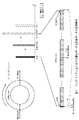
ところで、リングバッファ10にスロット単位で書き込まれるオーディオデータは、図12に示すように、MSB(Most Significant Bit)からLSB(Least Significant Bit)で示される実データと、当該実データの前段に記述されたヘッダとから構成されている。
By the way, as shown in FIG. 12, the audio data written in the
オーディオデータのヘッダにおいては、「Jump」としてゼロクロス近傍であるか否かに基づいてアドレスジャンプすべきオーディオデータがあるときは現在のアドレスがジャンプアドレス(詳しくは後述する)であることを表すフラグ情報が記述され、「GroupID2」、「GroupID1」、「GroupID0」として12トラックのうち所望のトラック同士を関連付けて1つのグループとした際のグループを識別するグループIDが記述され、「Offset」としてアナログディジタル変換後のオーディオデータに重畳している直流成分を除去するためのオフセット量が記述される。 In the header of the audio data, flag information indicating that the current address is a jump address (details will be described later) when there is audio data to be address jumped based on whether or not “Jump” is near the zero cross. “GroupID2”, “GroupID1”, and “GroupID0” describe a group ID for identifying a group when the desired tracks are associated with each other to form one group, and “Offset” is an analog digital signal. An offset amount for removing the DC component superimposed on the converted audio data is described.
図13に示すようにオーディオデータに直流成分が重畳している場合、波形全体の信号レベルが直流成分によって上がり、直流成分が重畳されていない本来のオーディオデータにおけるゼロクロスが検出できなくなってしまう。 As shown in FIG. 13, when a direct current component is superimposed on audio data, the signal level of the entire waveform is increased by the direct current component, and zero crossing in the original audio data on which the direct current component is not superimposed cannot be detected.
そこでオーディオ入出力制御装置は、直流成分を除去するためのオフセット量を予め検出し、それをオーディオデータのヘッダ情報における「Offset」に記述するようになされている。従ってオーディオ入出力制御装置は、直流成分が重畳しているオーディオデータについては当該直流成分を予め除去したバーチャルゼロクロスを検出することにより、直流成分が重畳していない本来のオーディオデータにおけるゼロクロスを検出し得るようになされている。 Therefore, the audio input / output control device detects an offset amount for removing the DC component in advance and describes it in “Offset” in the header information of the audio data. Therefore, the audio input / output control device detects a zero cross in the original audio data on which the DC component is not superimposed by detecting a virtual zero cross in which the DC component is removed in advance for the audio data on which the DC component is superimposed. Has been made to get.
またオーディオデータのヘッダ(図12)においては、「Low level」としてオーディオデータが例えば−60[dB]以下のローレベルであるときにその旨が記述され、「zcFlag1」としてオーディオデータがゼロクロス直前(図8)であるときにフラグ情報が記述され、「zcFlag0」としてオーディオデータがゼロクロス直後(図8)であるときにフラグ情報が記述されるようになされている。 In the audio data header (FIG. 12), “Low level” indicates that the audio data is at a low level of −60 [dB] or less, for example, and “zcFlag1” indicates that the audio data is immediately before the zero cross ( The flag information is described in the case of FIG. 8), and the flag information is described as “zcFlag0” when the audio data is immediately after the zero cross (FIG. 8).
従ってオーディオ入出力制御装置では、2048スロット毎のオーディオデータにおけるヘッダを参照して「zcFlag1」や「zcFlag0」のフラグ情報を確認することにより、オーディオデータの信号レベルがゼロクロス直前であるのか、ゼロクロス直後であるのかを瞬時に判別し得るようになされている。 Therefore, in the audio input / output control device, by checking the flag information of “zcFlag1” and “zcFlag0” with reference to the header in the audio data for each 2048 slot, the signal level of the audio data is just before the zero cross or just after the zero cross. So that it can be instantly determined.
またオーディオデータのヘッダでは、直流成分の重畳されているオーディオデータについては、「オフセットzcFlag1」として直流成分が重畳されていない本来のオーディオデータがゼロクロス直前であるときにフラグ情報が記述され、「オフセットzcFlag0」として直流成分が重畳していない本来のオーディオデータがゼロクロス直後であるときにフラグ情報が記述されるようになされている。 In the audio data header, for audio data with a DC component superimposed, flag information is described as “offset zcFlag1” when the original audio data with no DC component superimposed is just before zero crossing, and “offset The flag information is described as “zcFlag0” when the original audio data on which no DC component is superimposed is immediately after zero crossing.
ところでオーディオ入出力制御装置は、図8に示したように、オーディオデータの信号レベルをリングバッファ10のスロット単位で監視しており、その結果、オーディオデータの信号レベルがゼロレベル以下のときは符号ビットとして「1」をセットし、ゼロレベルを超えるときには符号ビットとして「0」をセットするようになされている。
By the way, as shown in FIG. 8, the audio input / output control apparatus monitors the signal level of the audio data for each slot of the
従ってオーディオ入出力制御装置は、例えばゼロクロス直前の時点(記号Wで示す)で書き込まれたオーディオデータの信号レベルがゼロレベル以下であるため符号ビットとして「1」をセットし、その1時点前(記号aで示す)のオーディオデータの信号レベルもゼロレベル以下であるため符号ビットとして「1」をセットし、そのゼロクロス直前の時点に対して1時点後(記号bで示す)のオーディオデータの信号レベルがゼロレベルを超えるため符号ビットとして「0」をセットする。 Therefore, the audio input / output control apparatus sets “1” as the sign bit because the signal level of the audio data written at the time immediately before the zero cross (indicated by the symbol W) is equal to or lower than the zero level, Since the audio data signal level (shown by symbol a) is also below the zero level, “1” is set as the sign bit, and the audio data signal after one time point (shown by symbol b) relative to the time point immediately before the zero crossing. Since the level exceeds the zero level, “0” is set as the sign bit.
また同様にオーディオ入出力制御装置は、例えばゼロクロス直後の時点(記号Wで示す)で書き込まれたオーディオデータの信号レベルがゼロレベルを超えるため符号ビットとして「0」をセットし、その1時点前(記号aで示す)のオーディオデータの信号レベルはゼロレベル以下であるため符号ビットとして「1」をセットし、そのゼロクロス直後の時点に対して1時点後(記号bで示す)のオーディオデータの信号レベルがゼロレベルを超えるため符号ビットとして「0」をセットする。 Similarly, the audio input / output control device sets “0” as the sign bit because the signal level of the audio data written at the time immediately after the zero crossing (indicated by the symbol W) exceeds the zero level. Since the signal level of the audio data (indicated by symbol a) is less than or equal to zero level, “1” is set as the sign bit, and the audio data of the audio data after one point (indicated by symbol b) is set immediately after the zero crossing. Since the signal level exceeds the zero level, “0” is set as the sign bit.
従ってオーディオ入出力制御装置は、この符号ビットをスロット毎に監視しておくことにより、符号ビットが「1」→「0」に変化するタイミングをゼロクロス時と判断することができ、そのときの符号ビットが「1」を示しているスロットをゼロクロス直前のオーディオデータとして把握し得ると共に「zcFlag1」のフラグ情報として「1」をセットし、符号ビットが「0」を示しているスロットをゼロクロス直後のオーディオデータとして把握し得ると共に「zcFlag0」のフラグ情報として「0」をセットするようになされている。 Therefore, the audio input / output control apparatus can determine the timing at which the code bit changes from “1” to “0” at the time of zero crossing by monitoring this code bit for each slot. A slot whose bit indicates “1” can be grasped as audio data immediately before the zero cross, and “1” is set as flag information of “zcFlag1”, and a slot whose sign bit indicates “0” immediately after the zero cross “0” is set as flag information of “zcFlag0” that can be grasped as audio data.
なおオーディオ入出力制御装置は、「オフセットzcFlag1」及び「オフセットzcFlag0」のフラグ情報についても、「zcFlag1」及び「zcFlag0」と同様に符号ビットに基づいて「1」又は「0」をセットするようになされている。 Note that the audio input / output control apparatus sets “1” or “0” for the flag information of “offset zcFlag1” and “offset zcFlag0” based on the sign bit as well as “zcFlag1” and “zcFlag0”. Has been made.
(2)オーディオ入出力制御装置の構成
実際上、図14に示すようにオーディオ入出力制御装置1は、2048スロット構成のリングバッファ10に合わせて2048サンプル毎のオーディオデータD1をローレベル検出器2、ゼロクロス検出器3及びリングバッファ10に入力する。
(2) Configuration of Audio Input / Output Control Device In practice, as shown in FIG. 14, the audio input /
ローレベル検出器2は、CPU(Central Processing Unit)構成でなる制御部4でゼロクロスを判断するために、オーディオデータD1の信号レベルが−60[dB]以下のローレベルであることを検出するようになされており、検出結果を制御部4へ出力する。
The
実際上、ローレベル検出器2は、図15に示すようにルーチンRT1の開始ステップから入って次のステップSP1へ移り、リングバッファ10に書き込むオーディオデータD1の信号レベルがローレベルであるか否かを判定する。
In practice, as shown in FIG. 15, the
ここで否定結果が得られるとローレベル検出器2は、次のステップSP2へ移り、ローレベルフラグとして「0」をセットし、次のステップSP4へ移って処理を終了する。一方、ステップSP1で肯定結果が得られると、ローレベル検出器2は次のステップSP3へ移り、ローレベルフラグとして「1」をセットし、次のステップSP4へ移って処理を終了する。
If a negative result is obtained here, the
ゼロクロス検出器3は、オーディオデータD1の信号レベルを監視することにより、当該オーディオデータの信号レベルが「0」レベルをクロスするか否かを検出し、その検出結果を制御部4へ出力する。
The zero
実際上、ゼロクロス検出器3は図16に示すようにルーチンRT2の開始ステップから入って次のステップSP11へ移り、オーディオデータD1に直流成分が重畳しているか否かをオフセット検出器5の検出結果に基づいて判別する。
Actually, the zero-
ここで図17に示すようにオフセット検出器5は、リングバッファ10の2048スロットに順次書き込むオーディオデータD1の信号レベルの合計値を2048で除算することにより平均値を算出し、当該平均値を直流成分のオフセット量として検出するようになされている。
Here, as shown in FIG. 17, the offset
ステップSP11で否定結果が得られると、ゼロクロス検出器5はオーディオデータD1に直流成分が重畳していないので何ら処理を施すことなく次のステップSP13へ移る。
If a negative result is obtained in step SP11, the zero-
一方ステップSP11で肯定結果が得られると、ゼロクロス検出器5はオーディオデータD1に直流成分が重畳しているのでリングバッファ10に書き込むオーディオデータD1から直流成分がないものと仮定したバーチャルゼロクロスを基準にして以降判断し、次のステップSP13へ移る。
On the other hand, if an affirmative result is obtained in step SP11, the zero-
ステップSP13においてゼロクロス検出器5は、図8に示したように、現時点(記号Wで示す)におけるオーディオデータD1の次の時点(記号bで示す)における符号ビットが「0」であるか否かを判定し、否定結果が得られると、次のステップSP16へ移るのに対し、肯定結果が得られると次のステップSP14へ移る。
In step SP13, as shown in FIG. 8, the zero
ステップSP14においてゼロクロス検出器5は、現時点(記号Wで示す)におけるオーディオデータD1の符号ビットが「1」であるか否かを判定し、否定結果が得られると記号Wbの並びとなる符号ビットが「00」となっていること、すなわちゼロクロスしていないことを表しており、このとき次のステップSP16へ移る。
In step SP14, the zero-
一方ステップSP14で肯定結果が得られると、記号Wbの並びとなる符号ビットが「10」となっていること、すなわちゼロクロスしていることを表しており、このときゼロクロス検出器5は次のステップSP15へ移り、ゼロクロス直前における「zcFlag1」のフラグ情報として「1」をセットした後、ステップSP19へ移って処理を終了する。
On the other hand, if an affirmative result is obtained in step SP14, this indicates that the sign bit of the arrangement of the symbols Wb is “10”, that is, zero crossing. At this time, the zero
ステップSP16においてゼロクロス検出器5は、現時点(記号Wで示す)におけるオーディオデータD1の前時点(記号aで示す)における符号ビットが「1」であるか否かを判定し、否定結果が得られると、ステップSP19へ移って処理を終了するのに対し、肯定結果が得られると次のステップSP17へ移る。
In step SP16, the zero
ステップSP17においてゼロクロス検出器5は、現時点(記号Wで示す)におけるオーディオデータD1の符号ビットが「0」であるか否かを判定し、否定結果が得られると記号aWの並びとなる符号ビットが「11」となっていること、すなわちゼロクロスしていないことを検出し、ステップSP19へ移って処理を終了する。
In step SP17, the zero
一方ステップSP17で肯定結果が得られると、記号aWの並びとなる符号ビットが「10」となっていること、すなわちゼロクロスしていることを表しており、このときゼロクロス検出器5は次のステップSP18へ移り、ゼロクロス直後における「zcFlag0」のフラグ情報として「1」をセットした後、ステップSP19へ移って処理を終了する。
On the other hand, if an affirmative result is obtained in step SP17, it indicates that the sign bit in the sequence of the symbols aW is “10”, that is, zero-crossing. At this time, the zero-
ところでリングバッファ10は、上述した通り、2048スロット構成でなり、入力されたオーディオデータD1をライトアドレスジェネレータ6から供給される書込アドレスに従い書込速度48[kHz]±5%でスロット毎に書き込み、当該オーディオデータD1をリードアドレスジェネレータ7から供給される読出アドレスに従い一定の読出速度48[kHz]で読み出して出力するようになされている。
As described above, the
このときライトアドレスジェネレータ6及びリードアドレスジェネレータ7は、書込アドレス及び読出アドレスをライトスピード検出器8へ送出すると共に、制御部4へ送出するようになされている。
At this time, the write address generator 6 and the
ライトスピード検出器8は、読出アドレスと書込アドレスとの差分値kを算出することにより、書込速度と読出速度との速度差を検出するようになされており、その差分値kを制御部4へ送出する。
The
制御部4は、書込アドレス、読出アドレス及び当該読出アドレスと当該書込アドレスとの差分値kに基づいて、現時点におけるアドレス変更前の読出アドレスを何処にアドレスジャンプさせるべきかを判断してアドレスジャンプ先となるアドレス変更後の読出アドレスを決定し、当該アドレス変更後の読出アドレスをリングバッファ10に指示するようになされている。
Based on the write address, the read address, and the difference value k between the read address and the write address, the
(3)アドレスジャンプ処理手順
次に、オーディオ入出力制御装置1の制御部4がリングバッファ10に対する書込速度と読出速度との速度差に応じて読出アドレスをアドレスジャンプさせるアドレスジャンプ処理手順について、書込速度が読出速度よりも速い場合と、読出速度が書込速度よりも速い場合とに分けて説明する。
(3) Address Jump Processing Procedure Next, the address jump processing procedure in which the
(3−1)書込速度が読出速度よりも速い場合の読出アドレスジャンプ処理手順
オーディオ入出力制御装置1の制御部4は、アプリケーションプログラムであるアドレスジャンプ処理プログラムに従い、ビデオテープレコーダのプログラムプレイ機能が動作する際にビデオの変速再生処理に応じてオーディオデータの書込速度が読出速度よりも速い場合にオーディオの音程変化を起こさせることなく、かつオーディオの連続性を維持するための読出アドレスジャンプ処理手順について図18のフローチャートを用いて具体的に説明する。
(3-1) Reading Address Jump Processing Procedure When Writing Speed is Faster than Reading Speed The
実際上、オーディオ入出力制御装置1の制御部4は、ルーチンRT3の開始ステップから入ってステップSP21へ移り、リングバッファ10から読み出すべき現時点における読出アドレスに「1」を加算することにより次の読出アドレスへ移行し、次のステップSP22へ移る。
In practice, the
ステップSP22において制御部4は、次の読出アドレスに相当するリングバッファ10のスロットに書き込まれているオーディオデータD1のヘッダを参照し、当該ヘッダの「zcFlag1」又は「zcFlag0」のフラグ情報として「1」がセットされているか否かを判定する。
In step SP22, the
ここで肯定結果が得られると、このことは「zcFlag1」又は「zcFlag0」のフラグ情報として「1」がセットされていること、すなわち次の読出アドレスから読み出すべきオーディオデータD1がゼロクロス直前又はゼロクロス直後のデータであることを表しており、このとき制御部4は次のステップSP23へ移る。
If a positive result is obtained here, this means that "1" is set as the flag information of "zcFlag1" or "zcFlag0", that is, the audio data D1 to be read from the next read address is immediately before the zero cross or just after the zero cross. In this case, the
ステップSP23において制御部4は、ライトスピード検出器8により読出アドレスと書込アドレスとの差分値kを算出し、その差分値kが256(スロット)未満であるか、差分値kが1024(スロット)よりも大きいか、或いは差分値kが256(スロット)以上1024(スロット)以下の範囲であるかを判定する。
In step SP23, the
ここで図19に示すように、差分値kが1024(スロット)よりも大きい場合、このことは読出アドレスが書込アドレスに追い付かれるまでには相当の時間的余裕があることを表しており、このとき制御部4はステップSP32へ移って読出アドレスジャンプ処理を行うことなく終了する。
Here, as shown in FIG. 19, when the difference value k is larger than 1024 (slot), this means that there is a considerable time margin until the read address is caught up with the write address, At this time, the
また差分値kが256(スロット)以上1024(スロット)以下の範囲である場合、このことは読出アドレスに書込アドレスが次第に追い付いてきており、読出アドレスと書込アドレスとの差が初期ディレイの一定範囲(例えば1024スロット±100スロット)から外れる可能性が出てきたことを表しており、このとき制御部4は次のステップSP24へ移る。
If the difference value k is in the range of 256 (slots) to 1024 (slots), this means that the write address gradually catches up with the read address, and the difference between the read address and the write address is the initial delay. This indicates that there is a possibility that a certain range (for example, 1024 slots ± 100 slots) has come out. At this time, the
ステップSP24において制御部4は、読出アドレスをアドレスジャンプさせる際に、オーディオデータD1の信号レベル変化が少ないゼロクロス近傍で、かつ読出アドレスから近い先に位置するアドレスジャンプ予定の読出アドレスをフォワードゼロクロスアドレスとし、当該フォワードゼロクロスアドレスと読出アドレスとの差fkを算出する。
In step SP24, when the address jump is performed on the read address, the
そして制御部4は、その差fkが1024(スロット)以上の場合、フォワードゼロクロスアドレスへ読出アドレスをアドレスジャンプさせてしまうと、初期ディレイの一定範囲(例えば1024スロット±100スロット)から外れる可能性が高いのでステップSP32へ移って読出アドレスジャンプ処理を行うことなく終了する。
Then, if the difference fk is 1024 (slots) or more, the
一方、制御部4は差fkが1024(スロット)よりも小さい場合、フォワードゼロクロスアドレスへ読出アドレスをアドレスジャンプさせても、初期ディレイの一定範囲(例えば1024スロット±100スロット)に収まる可能性が高いので読出アドレスジャンプ処理を行うべく次のステップSP26へ移る。
On the other hand, when the difference fk is smaller than 1024 (slots), the
ステップSP23において差分値kが256(スロット)よりも小さい場合、このことは読出アドレスが書込アドレスに追い付かれる直前の状態にあることを表しており、このとき制御部4は次のステップSP25へ移る。
When the difference value k is smaller than 256 (slot) in step SP23, this indicates that the read address is in a state immediately before the write address is caught up, and at this time, the
ステップSP25において制御部4は、読出アドレスをアドレスジャンプさせる際に、オーディオデータD1の信号レベル変化が少ないゼロクロス近傍で、かつ読出アドレスから遠い先に位置するアドレスジャンプ予定の読出アドレスをモアフォワードゼロクロスアドレスとし、読出アドレスと当該モアフォワードゼロクロスアドレスとの差mkを算出する。
In step SP25, when the address jump is performed on the read address, the
そして制御部4は、その差mkが1024(スロット)以上の場合、モアフォワードゼロクロスアドレスへ読出アドレスをアドレスジャンプさせてしまうと、初期ディレイの一定範囲(例えば1024スロット±100スロット)から外れる可能性が高いのでステップSP32へ移って読出アドレスジャンプ処理を行うことなく終了する。
If the difference mk is equal to or greater than 1024 (slots), the
一方、制御部4は差mkが1024(スロット)よりも小さい場合、モアフォワードゼロクロスアドレスへ読出アドレスをアドレスジャンプさせても、初期ディレイの一定範囲(例えば1024スロット±100スロット)に収まる可能性が高いので読出アドレスジャンプ処理を行うべく次のステップSP26へ移る。
On the other hand, when the difference mk is smaller than 1024 (slots), the
ステップSP26において制御部4は、読出アドレスをフォワードゼロクロスアドレス若しくはモアフォワードゼロクロスアドレスへアドレスジャンプさせることによりオーディオデータD1をデータ間引きして読出アドレスが書込アドレスに追い付かれることを予め防止すると共に、アドレスジャンプ前に読み出したオーディオデータD1とアドレスジャンプ後に読み出すオーディオデータD1との連続性を保持し、次のステップSP32へ移って処理を終了する。
In step SP26, the
これに対してステップSP22で否定結果が得られると、このことは「zcFlag1」又は「zcFlag0」のフラグ情報として「0」がセットされていること、すなわちゼロクロスとは無関係のオーディオデータD1であることを表しており、このとき制御部4は次のステップSP27へ移る。
On the other hand, if a negative result is obtained in step SP22, this means that “0” is set as the flag information of “zcFlag1” or “zcFlag0”, that is, audio data D1 unrelated to zero crossing. At this time, the
ここで制御部4は、例えオーディオデータD1がゼロクロスとは無関係であっても当該オーディオデータD1に直流成分が重畳しているためにゼロクロスを検出できていない可能性もあるため、次のステップSP27以降の処理へ移るようになされている。
Here, even if the audio data D1 is irrelevant to the zero cross, the
ステップSP27において制御部4は、当該オーディオデータD1のヘッダを参照し、当該ヘッダの「オフセットzcFlag1」又は「オフセットzcFlag0」のフラグ情報として「1」がセットされているか否かを判定する。
In step SP27, the
ここで否定結果が得られると、このことは「zcFlag1」又は「zcFlag0」と、「オフセットzcFlag1」又は「オフセットzcFlag0」のフラグ情報として何れも「0」がセットされていること、すなわち直流成分が重畳していないオーディオデータD1及び直流成分が重畳しているオーディオデータD1の双方共にゼロクロスしていないため、読出アドレスジャンプ処理を行うタイミングではないことを表しており、このとき制御部4はステップSP32へ移って処理を終了する。
If a negative result is obtained here, this means that “0” is set as the flag information of “zcFlag1” or “zcFlag0” and “offset zcFlag1” or “offset zcFlag0”, that is, the DC component is Since neither the audio data D1 that is not superimposed nor the audio data D1 that is superimposed with the DC component is zero-crossed, this indicates that it is not time to perform the read address jump process. At this time, the
一方ステップSP27で肯定結果が得られると、このことは直流成分が重畳しているオーディオデータD1について、直流成分が除去されたオーディオデータD1として考えた場合にバーチャルゼロクロス(図13)を検出し得たことを表しており、このとき制御部4は次のステップSP28へ移る。
On the other hand, if an affirmative result is obtained in step SP27, this means that a virtual zero cross (FIG. 13) can be detected when the audio data D1 on which the DC component is superimposed is considered as audio data D1 from which the DC component has been removed. At this time, the
ステップSP28において制御部4は、ライトスピード検出器8により読出アドレスと書込アドレスとの差分値kを算出し、その差分値kが256(スロット)未満であるか、差分値kが1024(スロット)よりも大きいか、或いは差分値kが256(スロット)以上1024(スロット)以下の範囲であるかを判定する。
In step SP28, the
ここで差分値kが1024(スロット)よりも大きい場合、このことは読出アドレスが書込アドレスに追い付かれるまでには相当の時間的余裕があることを表しており、このとき制御部4は上述のステップSP23と同様にステップSP32へ移って読出アドレスジャンプ処理を行うことなく終了する。 Here, when the difference value k is larger than 1024 (slot), this means that there is a considerable time margin until the read address catches up with the write address. As in step SP23, the process proceeds to step SP32 and ends without performing the read address jump process.
また差分値kが256(スロット)以上1024(スロット)以下の範囲である場合、このことは読出アドレスに書込アドレスが追い付いてきており、読出アドレスと書込アドレスとの差が初期ディレイの一定範囲(例えば1024スロット±100スロット)から外れる可能性があることを表しており、このとき制御部4は次のステップSP29へ移る。
If the difference value k is in the range of 256 (slots) to 1024 (slots), this means that the write address has caught up with the read address, and the difference between the read address and the write address is a constant initial delay. This indicates that there is a possibility of deviating from the range (for example, 1024 slots ± 100 slots). At this time, the
ステップSP29において制御部4は、読出アドレスをアドレスジャンプさせる際に、オーディオデータD1の信号レベル変化が少ないゼロクロス近傍で、かつ読出アドレスから近い先に位置するアドレスジャンプ予定の読出アドレスをフォワードオフセットゼロクロスアドレスとし、当該フォワードオフセットゼロクロスアドレスと現時点の読出アドレスとの差fokを算出する。
In step SP29, when the address jump is performed on the read address, the
そして制御部4は、その差fokが1024(スロット)以上の場合、フォワードオフセットゼロクロスアドレスへ読出アドレスをアドレスジャンプさせてしまうと、初期ディレイの一定範囲(例えば1024スロット±100スロット)から外れる可能性が高いのでステップSP32へ移って読出アドレスジャンプ処理を行うことなく終了する。
If the difference fok is 1024 (slots) or more, the
一方、制御部4は差fokが1024(スロット)よりも小さい場合、フォワードオフセットゼロクロスアドレスへ読出アドレスをアドレスジャンプさせても、初期ディレイの一定範囲(例えば1024スロット±100スロット)に収まる可能性が高いので読出アドレスジャンプ処理を行うべく次のステップSP30へ移る。
On the other hand, when the difference fok is smaller than 1024 (slots), the
さらにステップSP28における差分値kが256(スロット)よりも小さい場合、このことは読出アドレスが書込アドレスに追い付かれる直前の状態にあることを表しており、このとき制御部4は次のステップSP31へ移る。
Further, when the difference value k in step SP28 is smaller than 256 (slot), this indicates that the read address is in a state immediately before the write address is caught up, and at this time, the
ステップSP31において制御部4は、読出アドレスをアドレスジャンプさせる際に、オーディオデータD1の信号レベルの変化が少ないゼロクロス近傍で、かつ読出アドレスから遠い先に位置するアドレスジャンプ予定の読出アドレスをモアフォワードオフセットゼロクロスアドレスとし、当該モアフォワードオフセットゼロクロスアドレスと現時点の読出アドレスとの差mokを算出する。
In step SP31, when the address jump is performed on the read address, the
そして制御部4は、その差mokが1024(スロット)以上の場合、モアフォワードオフセットゼロクロスアドレスへ読出アドレスをアドレスジャンプさせてしまうと、初期ディレイの一定範囲(例えば1024スロット±100スロット)から外れる可能性が高いのでステップSP32へ移って読出アドレスジャンプ処理を行うことなく終了する。
When the difference mok is 1024 (slots) or more, the
一方、制御部4は差mokが1024(スロット)よりも小さい場合、モアフォワードゼロクロスアドレスへ読出アドレスをアドレスジャンプさせても、初期ディレイの一定範囲(例えば1024スロット±100スロット)に収まる可能性が高いので読出アドレスジャンプ処理を行うべく次のステップSP30へ移る。
On the other hand, if the difference mok is smaller than 1024 (slots), the
ステップSP30において制御部4は、読出アドレスをフォワードオフセットゼロクロスアドレス若しくはモアフォワードオフセットゼロクロスアドレスへアドレスジャンプさせることにより直流成分が重畳しているオーディオデータD1をデータ間引きして読出アドレスが書込アドレスに追い付かれることを予め防止すると共に、アドレスジャンプ前に読み出した直流成分が重畳しているオーディオデータD1とアドレスジャンプ後に読み出す直流成分が重畳しているオーディオデータD1との連続性を保持し、次のステップSP32へ移って処理を終了する。
In step SP30, the
(3−2)読出速度が書込速度よりも速い場合の読出アドレスジャンプ処理手順
オーディオ入出力制御装置1の制御部4は、アプリケーションプログラムであるアドレスジャンプ処理プログラムに従い、ビデオテープレコーダのプログラムプレイ機能が動作する際にビデオの変速再生処理に応じてオーディオデータD1の読出速度が書込速度よりも速い場合にオーディオの音程変化を起こさせることなく、かつオーディオの連続性を維持するための読出アドレスジャンプ処理手順について図20のフローチャートを用いて具体的に説明する。
(3-2) Read Address Jump Processing Procedure when Reading Speed is Faster than Writing Speed The
実際上、オーディオ入出力制御装置1の制御部4は、ルーチンRT4の開始ステップから入ってステップSP41へ移り、リングバッファ10から読み出すべき現時点における読出アドレスに「1」を加算することにより次の読出アドレスへ移行し、次のステップSP42へ移る。
In practice, the
ステップSP42において制御部4は、次の読出アドレスに相当するリングバッファ10のスロットに書き込まれているオーディオデータD1のヘッダを参照し、当該ヘッダの「zcFlag1」又は「zcFlag0」のフラグ情報として「1」がセットされているか否かを判定する。
In step SP42, the
ここで肯定結果が得られると、このことは「zcFlag1」又は「zcFlag0」のフラグ情報として「1」がセットされていること、すなわち次の読出アドレスから読み出すべきオーディオデータD1がゼロクロス直前又はゼロクロス直後のデータであることを表しており、このとき制御部4は次のステップSP43へ移る。
If a positive result is obtained here, this means that "1" is set as the flag information of "zcFlag1" or "zcFlag0", that is, the audio data D1 to be read from the next read address is immediately before the zero cross or just after the zero cross. In this case, the
ステップSP43において制御部4は、ライトスピード検出器8により書込アドレスと読出アドレスとの差分値k´を算出し、その差分値k´が256(スロット)未満であるか、差分値k´が1024(スロット)よりも大きいか、或いは差分kが256(スロット)以上1024(スロット)以下の範囲であるかを判定する。
In step SP43, the
ここで図21に示すように、差分値k´が1024(スロット)よりも大きい場合、このことは書込アドレスが読出アドレスに追い付かれるまでには相当の時間的余裕があることを表しており、このとき制御部4はステップSP52へ移って読出アドレスジャンプ処理を行うことなく終了する。
Here, as shown in FIG. 21, when the difference value k ′ is larger than 1024 (slot), this means that there is a considerable time margin until the write address catches up with the read address. At this time, the
また差分値k´が256(スロット)以上1024(スロット)以下の範囲である場合、このことは書込アドレスに読出アドレスが次第に追い付いてきており、書込アドレスと読出アドレスとの差が初期ディレイの一定範囲(例えば1024スロット±100スロット)から外れる可能性が出てきたことを表しており、このとき制御部4は次のステップSP44へ移る。
If the difference value k ′ is in the range of 256 (slots) to 1024 (slots), this means that the read address gradually catches up with the write address, and the difference between the write address and the read address is the initial delay. This means that there is a possibility that the predetermined range (for example, 1024 slots ± 100 slots) has come out, and at this time, the
ステップSP44において制御部4は、読出アドレスをアドレスジャンプさせる際に、オーディオデータD1の信号レベル変化が少ないゼロクロス近傍で、かつ読出アドレスから少し戻した先に位置するアドレスジャンプ予定の読出アドレスをバックワードゼロクロスアドレスとし、読出アドレスと当該バックワードゼロクロスアドレスとの差bk´を算出する。
In step SP44, when the address jump is made to the read address, the
そして制御部4は、その差bk´が1024(スロット)以上の場合、バックワードゼロクロスアドレスへ読出アドレスをアドレスジャンプさせてしまうと、初期ディレイの一定範囲(例えば1024スロット±100スロット)から外れる可能性が高いので、ステップSP52へ移って読出アドレスジャンプ処理を行うことなく終了する。
When the difference bk ′ is 1024 (slots) or more, the
一方、制御部4は差bk´が1024(スロット)よりも小さい場合、バックワードゼロクロスアドレスへ読出アドレスをアドレスジャンプさせても、初期ディレイの一定範囲(例えば1024スロット±100スロット)に収まる可能性が高いので読出アドレスジャンプ処理を行うべく次のステップSP46へ移る。
On the other hand, when the difference bk ′ is smaller than 1024 (slots), the
さらにステップSP43における差分値k´が256(スロット)よりも小さい場合、このことは書込アドレスが読出アドレスに追い付かれる直前の状態にあることを表しており、このとき制御部4は次のステップSP45へ移る。
Further, when the difference value k ′ in step SP43 is smaller than 256 (slot), this indicates that the write address is in a state immediately before the read address is caught up. At this time, the
ステップSP45において制御部4は、読出アドレスをアドレスジャンプさせる際に、オーディオデータD1の信号レベルの変化が少ないゼロクロス近傍で、かつ読出アドレスから大きく戻した先に位置するアドレスジャンプ予定の読出アドレスをモアバックワードゼロクロスアドレスとし、当該モアバックワードゼロクロスアドレスと読出アドレスとの差mk´を算出する。
In step SP45, when the address jump is performed on the read address, the
そして制御部4は、その差mk´が1024(スロット)以上の場合、モアバックワードゼロクロスアドレスへ読出アドレスをアドレスジャンプさせてしまうと、初期ディレイの一定範囲(例えば1024スロット±100スロット)から外れる可能性が高いのでステップSP52へ移って読出アドレスジャンプ処理を行うことなく終了する。
When the difference mk ′ is 1024 (slots) or more, the
一方、制御部4は差mk´が1024(スロット)よりも小さい場合、モアバックワードゼロクロスアドレスへ読出アドレスをアドレスジャンプさせても、初期ディレイの一定範囲(例えば1024スロット±100スロット)に収まる可能性が高いので読出アドレスジャンプ処理を行うべく次のステップSP46へ移る。
On the other hand, when the difference mk ′ is smaller than 1024 (slots), the
ステップSP46において制御部4は、読出アドレスをバックワードゼロクロスアドレス若しくはモアバックワードゼロクロスアドレスへアドレスジャンプさせることにより、同一のオーディオデータD1を再度読み出しながらデータ補間して書込アドレスが読出アドレスに追い付かれることを予め防止すると共にし、アドレスジャンプ前に読み出したオーディオデータD1とアドレスジャンプ後に読み出すオーディオデータD1との連続性を保持し、次のステップSP52へ移って処理を終了する。
In step SP46, the
これに対してステップSP42で否定結果が得られると、このことは「zcFlag1」又は「zcFlag0」のフラグ情報として「0」がセットされていること、すなわちゼロクロスとは無関係のオーディオデータD1であることを表しており、このとき制御部4は次のステップSP47へ移る。
On the other hand, if a negative result is obtained in step SP42, this means that "0" is set as the flag information of "zcFlag1" or "zcFlag0", that is, audio data D1 unrelated to zero crossing. In this case, the
ここで制御部4は、例えオーディオデータD1がゼロクロスとは無関係であっても当該オーディオデータD1に直流成分が重畳しているためにゼロクロスを検出できていない可能性もあるため、次のステップSP47以降の処理へ移るようになされている。
Here, even if the audio data D1 is irrelevant to the zero cross, the
ステップSP47において制御部4は、当該オーディオデータD1のヘッダを参照し、当該ヘッダの「オフセットzcFlag1」又は「オフセットzcFlag0」のフラグ情報として「1」がセットされているか否かを判定する。
In step SP47, the
ここで否定結果が得られると、このことは「zcFlag1」又は「zcFlag0」と、「オフセットzcFlag1」又は「オフセットzcFlag0」のフラグ情報として何れも「0」がセットされていること、すなわち直流成分が重畳していないオーディオデータD1及び直流成分が重畳しているオーディオデータD1の双方共にゼロクロスしていないため、読出アドレスジャンプ処理を行うタイミングではないことを表しており、このとき制御部4はステップSP52へ移って処理を終了する。
If a negative result is obtained here, this means that “0” is set as the flag information of “zcFlag1” or “zcFlag0” and “offset zcFlag1” or “offset zcFlag0”, that is, the DC component is Since neither the audio data D1 that is not superimposed nor the audio data D1 that is superimposed with the DC component is zero-crossed, this indicates that it is not time to perform the read address jump process. At this time, the
一方ステップSP47で肯定結果が得られると、このことは直流成分が重畳しているオーディオデータD1について、直流成分が除去されたオーディオデータD1として考えた場合にバーチャルゼロクロスを検出し得たことを表しており、このとき制御部4は次のステップSP48へ移る。
On the other hand, if an affirmative result is obtained in step SP47, this indicates that the virtual zero cross can be detected when the audio data D1 on which the DC component is superimposed is considered as the audio data D1 from which the DC component is removed. At this time, the
ステップSP48において制御部4は、ライトスピード検出器8により書込アドレスと読出アドレスとの差分値k´を算出し、その差分値k´が256(スロット)未満であるか、差分値k´が1024(スロット)よりも大きいか、或いは差分値k´が256(スロット)以上1024(スロット)以下の範囲であるかを判定する。
In step SP48, the
ここで差分値k´が1024(スロット)よりも大きい場合、このことは書込アドレスが読出アドレスに追い付かれるまでには相当の余裕があることを表しており、このとき制御部4は上述のステップSP43と同様にステップSP52へ移って読出アドレスジャンプ処理を行うことなく終了する。 Here, if the difference value k ′ is larger than 1024 (slot), this means that there is a considerable margin until the write address is caught up with the read address. Similar to step SP43, the process proceeds to step SP52 and ends without performing the read address jump process.
またステップSP48における差分値k´が256(スロット)以上1024(スロット)以下の範囲である場合、このことは書込アドレスに読出アドレスが追い付いてきており、書込アドレスと読出アドレスとの差が初期ディレイの一定範囲(例えば1024スロット±100スロット)から外れる可能性が出てきたことを表しており、このとき制御部4は次のステップSP49へ移る。
When the difference value k ′ in step SP48 is in the range of 256 (slots) to 1024 (slots), this means that the read address has caught up with the write address, and the difference between the write address and the read address is This indicates that there is a possibility that the initial delay is out of a certain range (for example, 1024 slots ± 100 slots). At this time, the
ステップSP49において制御部4は、読出アドレスをアドレスジャンプさせる際に、オーディオデータD1の信号レベルの変化が少ないゼロクロス近傍で、かつ読出アドレスから少し戻した先に位置するアドレスジャンプ予定の読出アドレスをバックワードオフセットゼロクロスアドレスとし、読出アドレスと当該バックワードオフセットゼロクロスアドレスとの差bok´を算出する。
In step SP49, when the address jump is made to the read address, the
そして制御部4は、その差bok´が1024(スロット)以上の場合、バックワードオフセットゼロクロスアドレスへ読出アドレスをアドレスジャンプさせてしまうと、初期ディレイの一定範囲(例えば1024スロット±100スロット)から外れる可能性が高いのでステップSP52へ移って読出アドレスジャンプ処理を行うことなく終了する。
If the difference bok ′ is 1024 (slots) or more, the
一方、制御部4は差bok´が1024(スロット)よりも小さい場合、バックワードゼロクロスアドレスへ読出アドレスをアドレスジャンプさせても、初期ディレイの一定範囲(例えば1024スロット±100スロット)に収まる可能性が高いので読出アドレスジャンプ処理を行うべく次のステップSP50へ移る。
On the other hand, when the difference “bok ′” is smaller than 1024 (slots), the
さらにステップSP48における差分値k´が256(スロット)よりも小さい場合、このことは書込アドレスが読出アドレスに追い付かれる直前の状態にあることを表しており、このとき制御部4は次のステップSP51へ移る。
Further, when the difference value k ′ in step SP48 is smaller than 256 (slot), this indicates that the write address is in a state immediately before the read address is caught up. At this time, the
ステップSP51において制御部4は、読出アドレスをアドレスジャンプさせる際に、オーディオデータD1の信号レベルの変化が少ないゼロクロス近傍で、かつ読出アドレスから遠く戻す先に位置するアドレスジャンプ予定の読出アドレスをモアバックワードオフセットゼロクロスアドレスとし、当該モアバックワードオフセットゼロクロスアドレスと読出アドレスとの差mok´を算出する。
In step SP51, when the address jump is performed on the read address, the
そして制御部4は、その差mok´が1024(スロット)以上の場合、モアバックワードオフセットゼロクロスアドレスへ読出アドレスをアドレスジャンプさせてしまうと、初期ディレイの一定範囲(例えば1024スロット±100スロット)から外れる可能性が高いのでステップSP52へ移って読出アドレスジャンプ処理を行うことなく終了する。
Then, if the difference mok ′ is 1024 (slots) or more, the
一方、制御部4は差mok´が1024(スロット)よりも小さい場合、モアバックワードゼロクロスアドレスへ読出アドレスをアドレスジャンプさせても、初期ディレイの一定範囲(例えば1024スロット±100スロット)に収まる可能性が高いので読出アドレスジャンプ処理を行うべく次のステップSP50へ移る。
On the other hand, when the difference mok ′ is smaller than 1024 (slots), the
ステップSP50において制御部4は、読出アドレスをバックワードオフセットゼロクロスアドレス若しくはモアバックワードオフセットゼロクロスアドレスへアドレスジャンプさせることにより、直流成分が重畳しているオーディオデータD1を再度読み出しながらデータ補間して書込アドレスが読出アドレスに追い付かれることを予め防止すると共に、アドレスジャンプ前に読み出した直流成分が重畳しているオーディオデータD1とアドレスジャンプ後に読み出す直流成分が重畳しているオーディオデータD1との連続性を保持し、次のステップSP52へ移って処理を終了する。
In step SP50, the
(4)動作及び効果
以上の構成において、オーディオ入出力制御装置1の制御部4は、リングバッファ10にオーディオデータD1を書込速度48[kHz]±5%で書き込み、当該リングバッファ10から一定の読出速度48[kHz]で読み出す際、書込速度と読出速度との速度差を検出し、当該検出した速度差に応じて書込アドレスが読出アドレスを追い越したり、読出アドレスが書込アドレスを追い越すことがないように、読出アドレスを強制的にアドレスジャンプさせる。
(4) Operation and Effect In the above configuration, the
このときオーディオ入出力制御装置1の制御部4は、ゼロクロス直前の読出アドレスと、ゼロクロス直後の読出アドレスとを結ぶようにアドレスジャンプさせることにより、アドレスジャンプ前の読出アドレスに対応したオーディオデータD1と、アドレスジャンプ後の読出アドレスに対応したオーディオデータD1との間で信号レベルの変化を極力少なくすることができるため、実際上アドレスジャンプによってオーディオデータD1の連続性が途切れても、ユーザの聴感的にはオーディオデータD1の連続性を維持しているかのような印象を与え、かつ音程変化のない音声を出力することができる。
At this time, the
またオーディオ入出力制御装置1の制御部4は、読出アドレスをアドレスジャンプさせることにより、当該読出アドレスを先に進ませる場合には当該オーディオデータD1をデータ間引きすることになり、当該読出アドレスを後ろに戻す場合には同じオーディオデータD1を再度読み出してデータ補間することになるため、変速再生処理したビデオに対してオーディオを時間的に合わせることができる。
Also, the
このようにオーディオ入出力制御装置1の制御部4は、読出アドレスのアドレスジャンプを行うだけで上述の効果を奏するようになされており、かくして多くの加算や乗算等の演算が必要なクロスフェード処理を行う場合と比較して格段に信号処理量を低減することができる。
As described above, the
さらにオーディオ入出力制御装置1の制御部4は、読出アドレスと書込アドレスとの差として1024スロット±100スロット程度の一定範囲からなる初期ディレイを保持するように制御していることにより、書込アドレスが読出アドレスを追い越したり、読出アドレスが書込アドレスを追い越すといったリスクを予め回避することができる。
Furthermore, the
以上の構成によれば、オーディオ入出力制御装置1の制御部4は、ビデオテープレコーダがプログラムプレイ機能を動作させ、ビデオの変速再生処理に合わせて音程を変化させることなく音声を出力する場合、信号処理量を大幅に低減しつつ当該オーディオデータD1の品位についても保持することができる。
According to the above configuration, the
(5)他の実施の形態
なお上述の実施の形態においては、2048スロットのリングバッファ10を用いるようにした場合について述べたが、本発明はこれに限らず、オーディオの品位を考慮して4096スロットのリングバッファを用いたり、初期ディレイを少なくする点を考慮して1048スロットのリングバッファを用いるようにしても良い。
(5) Other Embodiments In the above-described embodiment, the case where the 2048-
また上述の実施の形態においては、オフセット検出器5として、リングバッファ10の2048スロットに順次書き込むオーディオデータD1の信号レベルの合計値を2048で除算することにより平均値を算出し、当該平均値を直流成分のオフセット量として検出するようにした場合について述べたが、本発明はこれに限らず、オーディオデータD1の最大値と最小値の中間値を直流成分のオフセット量として検出するようにしても良い。
In the above-described embodiment, the offset
さらに上述の実施の形態においては、オーディオデータD1を書込速度48[kHz]±5%でスロット毎に書き込む場合に本発明を適用するようにした場合について述べたが、本発明はこれに限らず、オーディオデータD1のリングバッファ10に対する書込速度が48[kHz]±5%に固定されるのではなく変動する場合に本発明を適用するようにしても良い。
Further, in the above-described embodiment, the case where the present invention is applied when the audio data D1 is written for each slot at the writing speed 48 [kHz] ± 5% has been described. However, the present invention is not limited to this. Instead, the present invention may be applied when the writing speed of the audio data D1 to the
さらに上述の実施の形態においては、プログラムプレイ機能を動作させる際にビデオの変速再生処理に合わせてオーディオデータD1の入出力を制御するようにした場合について述べたが、本発明はこれに限らず、ビデオの変速再生処理とは無関係にオーディオデータD1の入出力を制御するようにしても良い。 Furthermore, in the above-described embodiment, the case where the input / output of the audio data D1 is controlled in accordance with the video variable speed playback process when the program play function is operated has been described, but the present invention is not limited to this. The input / output of the audio data D1 may be controlled regardless of the video variable speed playback process.
さらに上述の実施の形態においては、本発明の入出力制御装置1をビデオテープレコーダに搭載するようにした場合について述べたが、本発明はこれに限らず、ビデオ編集装置やボイスレコーダ、オーディオ録音装置、パーソナルコンピュータ、ハードディスクレコーダ又は携帯電話機等のその他種々の電子機器に搭載するようにしても良い。
Further, in the above-described embodiment, the case where the input /
さらに上述の実施の形態においては、本発明のオーディオ入出力制御装置をメモリとしてのリングバッファ10、アドレス変更手段及び読出アドレス決定手段としての制御部4によって構成するようにした場合について述べたが、本発明はこれに限らず、その他種々の構成でなるメモリ、アドレス変更手段及び読出アドレス決定手段によってオーディオ入出力制御装置を構成するようにしても良い。
Furthermore, in the above-described embodiment, the case where the audio input / output control device of the present invention is configured by the
本発明のオーディオ入出力制御装置及びオーディオ入出力制御方法は、例えばオーディオデータを高品位のまま時間伸張又は時間圧縮する用途に適用することができる。 The audio input / output control apparatus and audio input / output control method of the present invention can be applied to, for example, an application in which audio data is time-extended or time-compressed with high quality.
1……オーディオ入出力制御装置、2……ローレベル検出器、3……ゼロクロス検出器、4……制御部、5……オフセット検出器、6……ライトアドレスジェネレータ、7……リードアドレスジェネレータ、8……ライトスピード検出器、10……リングバッファ。
DESCRIPTION OF
Claims (4)
上記オーディオデータの上記リングバッファに対する書込アドレスと、上記リングバッファに蓄積された上記オーディオデータを一定速度で読み出す際の読出アドレスとの差分値に基づいて上記リングバッファに対する読出アドレスを強制的に変更するか否かを判定するアドレス変更判定手段と、
上記アドレス変更判定手段により上記読出アドレスを変更する判定がされたとき、上記オーディオデータの信号レベルがゼロクロス直前のアドレス位置となる変更前の読出アドレスからゼロクロス直後のアドレス位置となる変更予定の読出アドレスを設定する読出アドレス設定手段と、
上記読出アドレス設定手段により設定された上記変更予定の読出アドレスと上記変更前の読出アドレスとの差に基づいて上記リングバッファに対する上記変更予定の読出アドレスと上記書込アドレスとの間に生じる初期ディレイを確保できると判断したとき、上記変更前の読出アドレスを上記変更予定の読出アドレスへアドレスジャンプさせるアドレス変更手段と
を具えることを特徴とするオーディオ入出力制御装置。 A ring buffer for a predetermined number of slots for storing externally input audio data;
The read address for the ring buffer is forcibly changed based on the difference value between the write address of the audio data for the ring buffer and the read address for reading the audio data stored in the ring buffer at a constant speed. Address change determination means for determining whether or not to do;
When the decision to change the read address by the address change determination unit, the read address of the planned changes the signal level of the audio data is comprised of read address before the change as the zero cross just before the address position the address position immediately zero crossing Read address setting means for setting
An initial delay generated between the read address to be changed and the write address for the ring buffer based on the difference between the read address to be changed set by the read address setting means and the read address before the change. An audio input / output control device comprising: an address changing means for jumping the read address before the change to the read address to be changed when it is determined that the read address can be secured.
上記オーディオデータに不要な直流成分が重畳していることを検出したときは、当該直流成分を除去した状態で上記変更後の読出アドレスを設定する
請求項1に記載のオーディオ入出力制御装置。 The read address setting means includes:
The audio input / output control apparatus according to claim 1, wherein when it is detected that an unnecessary DC component is superimposed on the audio data, the changed read address is set in a state where the DC component is removed.
上記オーディオデータの信号レベルがゼロレベル以下のときや、ゼロレベルを超えるときに符号ビットをセットし、その符号ビットに基づいて上記ゼロクロス直前又は上記ゼロクロス直後を判断する
請求項1に記載のオーディオ入出力制御装置。 The read address setting means includes:
2. The audio input according to claim 1, wherein a sign bit is set when the signal level of the audio data is equal to or lower than zero level or exceeds the zero level, and immediately before the zero cross or immediately after the zero cross is determined based on the sign bit. Output control device.
上記アドレス変更判定ステップにより上記読出アドレスを変更する判定がされたとき、上記オーディオデータの信号レベルがゼロクロス直前のアドレス位置となる変更前の読出アドレスからゼロクロス直後のアドレス位置となる変更予定の読出アドレスを読出アドレス設定手段により設定する読出アドレス設定ステップと、
上記読出アドレス設定ステップにより設定された上記変更予定の読出アドレスと上記変更前の読出アドレスとの差に基づいて上記リングバッファに対する上記変更予定の読出アドレスと上記書込アドレスとの間に生じる初期ディレイを確保できると判断したとき、アドレス変更手段により上記変更前の読出アドレスを上記変更予定の読出アドレスへアドレスジャンプさせるアドレス変更ステップと
を有するオーディオ入出力制御方法。 The ring is based on a difference value between a write address for a ring buffer for a predetermined number of slots for storing externally input audio data and a read address for reading the audio data stored in the ring buffer at a constant speed. An address change determination step for determining by the address change determination means whether to forcibly change the read address for the buffer;
When the above address change determining step determines to change the read address is the read address of the planned changes the signal level of the audio data is comprised of read address before the change as the zero cross just before the address position the address position immediately zero crossing A read address setting step for setting the
An initial delay generated between the read address to be changed and the write address for the ring buffer based on a difference between the read address to be changed set by the read address setting step and the read address before the change. And an address changing step of causing the address changing means to jump the read address before the change to the read address to be changed when the address change means determines that it can be secured.
Priority Applications (3)
| Application Number | Priority Date | Filing Date | Title |
|---|---|---|---|
| JP2005038102A JP4406838B2 (en) | 2005-02-15 | 2005-02-15 | Audio input / output control apparatus and audio input / output control method |
| US11/352,884 US7711444B2 (en) | 2005-02-15 | 2006-02-13 | Audio input/output control apparatus and audio input/output control method |
| CN200610007653A CN100583274C (en) | 2005-02-15 | 2006-02-15 | Audio input/output control apparatus and audio input/output control method |
Applications Claiming Priority (1)
| Application Number | Priority Date | Filing Date | Title |
|---|---|---|---|
| JP2005038102A JP4406838B2 (en) | 2005-02-15 | 2005-02-15 | Audio input / output control apparatus and audio input / output control method |
Publications (3)
| Publication Number | Publication Date |
|---|---|
| JP2006227110A JP2006227110A (en) | 2006-08-31 |
| JP2006227110A5 JP2006227110A5 (en) | 2006-10-12 |
| JP4406838B2 true JP4406838B2 (en) | 2010-02-03 |
Family
ID=36923456
Family Applications (1)
| Application Number | Title | Priority Date | Filing Date |
|---|---|---|---|
| JP2005038102A Expired - Fee Related JP4406838B2 (en) | 2005-02-15 | 2005-02-15 | Audio input / output control apparatus and audio input / output control method |
Country Status (3)
| Country | Link |
|---|---|
| US (1) | US7711444B2 (en) |
| JP (1) | JP4406838B2 (en) |
| CN (1) | CN100583274C (en) |
Families Citing this family (9)
| Publication number | Priority date | Publication date | Assignee | Title |
|---|---|---|---|---|
| KR101410523B1 (en) | 2007-11-16 | 2014-06-20 | 삼성전자주식회사 | Apparatus and method for controlling a buffer for processing voice data |
| JP4692610B2 (en) * | 2008-11-26 | 2011-06-01 | ソニー株式会社 | Signal transmission system, interface device, and signal transmission method |
| JP5671823B2 (en) * | 2010-03-24 | 2015-02-18 | 株式会社Jvcケンウッド | Harmonic generation method, harmonic generation apparatus, and program |
| JP5956936B2 (en) * | 2013-01-28 | 2016-07-27 | シナノケンシ株式会社 | Audio data reproduction speed conversion method and audio data reproduction speed conversion apparatus |
| TWI648732B (en) * | 2016-05-13 | 2019-01-21 | 景相科技股份有限公司 | Method for synchronously accessing audio data and audio playback system using the same |
| JP6904141B2 (en) | 2017-07-28 | 2021-07-14 | カシオ計算機株式会社 | Music generators, methods, programs, and electronic musical instruments |
| JP6922614B2 (en) | 2017-09-27 | 2021-08-18 | カシオ計算機株式会社 | Electronic musical instruments, musical tone generation methods, and programs |
| CN112423120B (en) * | 2020-01-22 | 2023-09-01 | 上海哔哩哔哩科技有限公司 | Audio time delay detection method and system |
| JP7299864B2 (en) * | 2020-09-24 | 2023-06-28 | Tvs Regza株式会社 | receiving device, computer program |
Family Cites Families (12)
| Publication number | Priority date | Publication date | Assignee | Title |
|---|---|---|---|---|
| JPS6175396A (en) | 1984-09-20 | 1986-04-17 | ティーオーエー株式会社 | Scale converter |
| JP3189587B2 (en) | 1994-09-14 | 2001-07-16 | 松下電器産業株式会社 | Audio time base converter |
| US5920842A (en) * | 1994-10-12 | 1999-07-06 | Pixel Instruments | Signal synchronization |
| JPH08202391A (en) | 1995-01-30 | 1996-08-09 | Sanyo Electric Co Ltd | Speaking speed changing device |
| US5850572A (en) * | 1996-03-08 | 1998-12-15 | Lsi Logic Corporation | Error-tolerant video display subsystem |
| JP2000138591A (en) | 1998-10-29 | 2000-05-16 | Sanyo Electric Co Ltd | Audio reproducing device |
| US6304924B1 (en) * | 1999-02-02 | 2001-10-16 | International Business Machines Corporation | Two lock-free, constant-space, multiple-(impure)-reader, single-writer structures |
| JP3420210B2 (en) | 1999-12-02 | 2003-06-23 | 松下電器産業株式会社 | Video recording device and video recording method |
| SE517156C2 (en) * | 1999-12-28 | 2002-04-23 | Global Ip Sound Ab | System for transmitting sound over packet-switched networks |
| US6977897B1 (en) * | 2000-05-08 | 2005-12-20 | Crossroads Systems, Inc. | System and method for jitter compensation in data transfers |
| JP2002232846A (en) | 2001-02-05 | 2002-08-16 | Matsushita Electric Ind Co Ltd | Video and audio processor and video and audio processing method |
| US7659904B2 (en) * | 2003-04-07 | 2010-02-09 | Ati Technologies Ulc | System and method for processing high priority data elements |
-
2005
- 2005-02-15 JP JP2005038102A patent/JP4406838B2/en not_active Expired - Fee Related
-
2006
- 2006-02-13 US US11/352,884 patent/US7711444B2/en not_active Expired - Fee Related
- 2006-02-15 CN CN200610007653A patent/CN100583274C/en not_active Expired - Fee Related
Also Published As
| Publication number | Publication date |
|---|---|
| CN100583274C (en) | 2010-01-20 |
| US7711444B2 (en) | 2010-05-04 |
| US20060193601A1 (en) | 2006-08-31 |
| JP2006227110A (en) | 2006-08-31 |
| CN1822188A (en) | 2006-08-23 |
Similar Documents
| Publication | Publication Date | Title |
|---|---|---|
| JP4406838B2 (en) | Audio input / output control apparatus and audio input / output control method | |
| US6526217B1 (en) | Method and apparatus for after recording of digital recording medium and method and apparatus for reproducing digital recording medium | |
| WO2006006685A1 (en) | Contents delivery system, client, server, contents delivery method and contents reproducing method | |
| JP2008537833A (en) | Apparatus and method for storing audio files | |
| JP4864460B2 (en) | REPRODUCTION DEVICE, REPRODUCTION METHOD, AND PROGRAM | |
| JP4247685B2 (en) | Multi-track audio control apparatus and multi-track audio control method | |
| JP2007250057A (en) | Sound reproducing device, sound reproducing method, and sound reproducing program | |
| US7385129B2 (en) | Music reproducing system | |
| JPS61255575A (en) | Sound recording system | |
| JP2014121049A (en) | Recorder, recording method and program | |
| JP2008076847A (en) | Decoder and signal processing system | |
| JP3173678B2 (en) | Memory control circuit and disk reproducing device | |
| JP2004220638A (en) | Video recording reproducing apparatus | |
| JP2006262045A (en) | Content reproducer | |
| JP3740976B2 (en) | Compound information recording device | |
| JP2676707B2 (en) | Mini disc player | |
| JP2001177803A (en) | Audio signal processing method, audio signal reproducing device, high fidelity video device, digital video device, and 8 mm video device | |
| JP2006301507A (en) | Device and method for dividing reproduction unit | |
| JP2004303409A (en) | Digital voice signal reproduction system | |
| JP2675457B2 (en) | Information playback device | |
| JP3322811B2 (en) | Optical disk drive | |
| JP3829944B2 (en) | Playback device | |
| JP3362012B2 (en) | Digital signal recording method, recording apparatus, and recording medium | |
| JP2005353181A (en) | Information processing device | |
| JP2008097781A (en) | Sound reproducing device |
Legal Events
| Date | Code | Title | Description |
|---|---|---|---|
| A521 | Request for written amendment filed |
Free format text: JAPANESE INTERMEDIATE CODE: A523 Effective date: 20060711 |
|
| A621 | Written request for application examination |
Free format text: JAPANESE INTERMEDIATE CODE: A621 Effective date: 20060711 |
|
| A977 | Report on retrieval |
Free format text: JAPANESE INTERMEDIATE CODE: A971007 Effective date: 20081224 |
|
| A131 | Notification of reasons for refusal |
Free format text: JAPANESE INTERMEDIATE CODE: A131 Effective date: 20090108 |
|
| A521 | Request for written amendment filed |
Free format text: JAPANESE INTERMEDIATE CODE: A523 Effective date: 20090303 |
|
| A131 | Notification of reasons for refusal |
Free format text: JAPANESE INTERMEDIATE CODE: A131 Effective date: 20090416 |
|
| A521 | Request for written amendment filed |
Free format text: JAPANESE INTERMEDIATE CODE: A523 Effective date: 20090511 |
|
| TRDD | Decision of grant or rejection written | ||
| A01 | Written decision to grant a patent or to grant a registration (utility model) |
Free format text: JAPANESE INTERMEDIATE CODE: A01 Effective date: 20091015 |
|
| A01 | Written decision to grant a patent or to grant a registration (utility model) |
Free format text: JAPANESE INTERMEDIATE CODE: A01 |
|
| A61 | First payment of annual fees (during grant procedure) |
Free format text: JAPANESE INTERMEDIATE CODE: A61 Effective date: 20091028 |
|
| FPAY | Renewal fee payment (event date is renewal date of database) |
Free format text: PAYMENT UNTIL: 20121120 Year of fee payment: 3 |
|
| LAPS | Cancellation because of no payment of annual fees |