JP4405115B2 - Information recording apparatus and information recording method - Google Patents
Information recording apparatus and information recording method Download PDFInfo
- Publication number
- JP4405115B2 JP4405115B2 JP2001266460A JP2001266460A JP4405115B2 JP 4405115 B2 JP4405115 B2 JP 4405115B2 JP 2001266460 A JP2001266460 A JP 2001266460A JP 2001266460 A JP2001266460 A JP 2001266460A JP 4405115 B2 JP4405115 B2 JP 4405115B2
- Authority
- JP
- Japan
- Prior art keywords
- period
- recording
- level
- laser
- mark
- Prior art date
- Legal status (The legal status is an assumption and is not a legal conclusion. Google has not performed a legal analysis and makes no representation as to the accuracy of the status listed.)
- Expired - Fee Related
Links
Images


Classifications
-
- G—PHYSICS
- G11—INFORMATION STORAGE
- G11B—INFORMATION STORAGE BASED ON RELATIVE MOVEMENT BETWEEN RECORD CARRIER AND TRANSDUCER
- G11B7/00—Recording or reproducing by optical means, e.g. recording using a thermal beam of optical radiation by modifying optical properties or the physical structure, reproducing using an optical beam at lower power by sensing optical properties; Record carriers therefor
- G11B7/004—Recording, reproducing or erasing methods; Read, write or erase circuits therefor
- G11B7/006—Overwriting
- G11B7/0062—Overwriting strategies, e.g. recording pulse sequences with erasing level used for phase-change media
-
- G—PHYSICS
- G11—INFORMATION STORAGE
- G11B—INFORMATION STORAGE BASED ON RELATIVE MOVEMENT BETWEEN RECORD CARRIER AND TRANSDUCER
- G11B7/00—Recording or reproducing by optical means, e.g. recording using a thermal beam of optical radiation by modifying optical properties or the physical structure, reproducing using an optical beam at lower power by sensing optical properties; Record carriers therefor
- G11B7/004—Recording, reproducing or erasing methods; Read, write or erase circuits therefor
- G11B7/0045—Recording
- G11B7/00456—Recording strategies, e.g. pulse sequences
Landscapes
- Optical Recording Or Reproduction (AREA)
- Optical Head (AREA)
Abstract
Description
【0001】
【発明の属する技術分野】
本発明は、レーザ光線などを利用して光ディスクに情報を記録する技術に属する。
【0002】
【従来の技術】
DVD−R(DVD-Recordable)、DVD−RW(DVD-Re-recordable)などの書き込み又は書き換え可能な光ディスクには、ディスクの記録面上にレーザ光を照射して情報を記録する。光ディスクの記録面上のレーザ光が照射された部分は、温度が上昇するために光ディスクを構成する光記録媒体に変化が生じ、これにより記録マークが記録面上に形成される。
【0003】
よって、記録すべき情報に応じた時間幅を有する記録パルスでレーザ光を変調して記録すべき信号に応じた長さのレーザパルスを生成し、これを光ディスクに照射することにより、記録すべき情報に応じた長さの記録マークを光ディスク上に形成することができる。
【0004】
一方、最近では1つの記録マークを1つのレーザパルスで形成するのではなく、複数の短いパルスを含むパルス列により記録マークを形成する手法が利用されている。このような手法はライトストラテジとも呼ばれ、単一の記録パルスを照射する方法に比べて、光ディスクの記録面上における熱蓄積が減少するので、記録マークが形成される記録面上の温度分布を均一化することができる。その結果、記録マークが涙滴形状となることを防止して好ましい形状の記録マークを形成することができる。
【0005】
上記の記録パルス列は、所定のリード(読取)パワーレベルとライト(書き込み)パワーレベルとの間で振幅が変動する複数のパルスにより構成されている。即ち、記録信号に従って、記録マークを形成しない光ディスクの記録面上の領域(以下、「スペース部」とも呼ぶ。)ではリードパワーでレーザ光が記録面上に照射され、記録マークを形成すべき光ディスクの記録面上の領域(以下、「マーク部」とも呼ぶ。)では、リードパワーとライトパワーの間で振幅が変化する記録パルス列に応じたパワーでレーザ光が記録面上に照射され、それにより記録マークが記録面上に形成される。
【0006】
【発明が解決しようとする課題】
しかし、記録パルスに対応するレーザパルスを光ディスクの記録面に照射すると、そのパルスの過渡応答により、記録パルスの照射後におけるレーザ照射レベル(バイアスレベル)が上昇することになる。記録パルスはリードパワーとライトパワーとの間で振幅が変動し、記録パルスの終了後は、理論的にはレーザ照射レベルは瞬時にリードパワーに戻る。しかし、現実には、記録パルスの終了時にレーザ照射レベルがライトパワーからリードパワーに瞬時に変化するために記録パルスの過渡応答が生じ、レーザ照射レベルは瞬間的にはリードパワーに戻らず、むしろ一定期間はレーザ照射レベルが上昇することになる。その結果、記録パルス終了後も短時間ではあるがレーザ照射レベルがリードパワーレベルより高い期間が生じる。これは熱干渉として次の記録マークの形成に影響を与えることがある。特に、次の記録マークまでの間のスペース期間が短い場合には、次の記録マークの形成時に上述の過渡応答による残留熱があるために、次の記録マークが正しく形成できなくなることがある。
【0007】
そして、この影響は、記録速度が増加した場合、つまり光ディスクに高速記録を行う場合には特に顕著となる。通常速度(低速)の記録の場合は、次の記録マークに対応するマーク期間までの時間がある程度確保できるので、上記過渡応答の影響が緩和されるが、記録速度が通常の2倍、3倍などと高速化すると、記録パルス列の時間的間隔が短くなるので、残留熱が残った状態で次の記録パルス列が到来することになり、上記過渡応答による残留熱が次の記録マークに対して熱干渉として影響する可能性が高くなる。
【0008】
さらに、記録速度が高速化すると、正しく記録マークを形成するために、記録速度の増加分に応じて記録パワーを上げてやる必要がある。そのため、上記の過渡応答によるレーザ照射レベルの上昇が大きくなり、悪影響が増大することになる。
【0009】
そして、上述のような、記録パルスの過渡応答に起因するレーザ照射レベルの増加は、記録パルスの印加後、即ち記録信号のスペース期間において生じるため、記録パルスのパルス幅などを調整して記録マーク形状を調整するライトストラテジ技術によっては、この影響を除去することはできない。
【0010】
本発明は、以上の点に鑑みてなされたものであり、高速記録時においても、記録パルス列の過渡応答の影響を排除して正しい記録マークを形成することが可能な情報記録装置及び方法を提供することを課題とする。
【0011】
【課題を解決するための手段】
本発明の1つの観点では、記録媒体にレーザ光を照射して、記録信号に応じた記録マークを形成する情報記録装置において、前記レーザ光を出射する光源と、前記記録信号に基づいて前記光源を駆動することにより、前記記録媒体上にレーザパルスを照射する制御手段と、を備え、前記制御手段は、前記記録信号のマーク期間中には、前記レーザパルスの出力レベルを、記録信号に対応して、通常レベルと、前記通常レベルよりも高い書込レベルとの間で変化させるマーク制御手段と、前記記録信号の少なくともいくつかの時間幅のスペース期間中に、所定期間にわたって、前記レーザパルスの出力レベルを、前記通常レベルより低いレベルに変化させるスペース制御手段と、備え、前記スペース制御手段は、時間幅が長いスペース期間においては所定の第1期間にわたって前記レーザパルスの出力レベルを前記低いレベルに変化させ、時間幅が短いスペース期間においては、前記第1期間より長い第2期間にわたって前記レーザパルスの出力レベルを前記低いレベルに変化させる。
【0012】
上記の情報記録装置によれば、記録信号に応じたパルス信号で光源を駆動することにより、記録信号に応じたレーザパルスが記録媒体上に照射される。記録信号は、記録マークを形成するマーク期間と、記録マークの形成が行われないスペース期間を有する。マーク期間中においては、レーザパルスの出力レベルは、通常レベルと書込レベルとの間で変化し、これにより記録マークが記録媒体上に形成される。一方、スペース期間中の所定の期間にわたって、レーザパルスの出力レベルは通常レベルより低いレベルに変化される。これにより、マーク期間中のレーザパルスの過渡応答に起因する、記録媒体への熱蓄積が減少し、その後のマーク期間において正しい記録マークが形成できる。また、短いスペース期間では、その前のマーク期間中のレーザパルスの過渡応答が次のマーク期間に影響を与えやすいので、より長い期間にわたってレーザパルスの出力レベルを低下させる。
【0013】
上記の情報記録装置の一態様では、前記通常レベルより低いレベルは、ゼロレベルとする。
【0014】
この態様によれば、スペース期間中に一時的にレーザパルスのレベルがゼロになるので、その間に記録媒体に対する熱の蓄積が十分に減少する。
【0018】
上記の情報記録装置のさらに他の一態様では、前記スペース制御手段は、全ての時間幅のスペース期間において前記レーザパルスの出力レベルを前記通常レベルより低いレベルに変化させる。
【0019】
この態様によれば、全ての時間幅のスペース期間でレーザパルスの出力レベルを下げるので、マーク期間中のレーザパルスの過渡応答による熱干渉の影響を効果的に排除することができる。
【0022】
上記の情報記録装置のさらに他の一態様では、前記時間幅が短いスペース期間は3T又は4Tのスペース期間とし、前記時間幅が長いスペース期間は5T以上のスペース期間とすることができる。
【0029】
上記の情報記録装置のさらに他の一態様では、前記記録媒体は1回に限り記録が可能な記録媒体とし、前記通常レベルは読取レベルとすることができる。
【0030】
この態様によれば、CD−R、DVD−Rなどの記録媒体に本発明を適用することができる。
【0031】
上記の情報記録装置のさらに他の一態様では、前記記録媒体は複数回にわたって書き込み及び消去が可能な記録媒体とし、前記通常レベルは消去レベルとすることができる。
【0032】
この態様によれば、CD−RW、DVD−RWなどの記録媒体に本発明を適用することができる。
【0033】
上記の情報記録装置のさらに他の一態様では、前記スペース制御手段は、スペース期間の先頭から、前記レーザパルスの出力レベルを前記通常レベルより低いレベルに変化させる。
【0034】
この態様によれば、スペース期間の先頭からレーザパルスの出力レベルを下げるので、書込レベルのレーザパルスが照射されるマーク期間終了後直ちにレーザパワーを下げて過渡応答の影響を効率的に排除することができる。
【0035】
本発明の他の観点では、記録媒体にレーザ光を照射して、記録信号に応じた記録マークを形成する情報記録方法において、前記レーザ光を出射するステップと、前記記録信号に基づいて光源を駆動することにより、前記記録媒体上にレーザパルスを照射するステップと、を有し、前記レーザパルスを照射するステップは、前記記録信号のマーク期間中には、前記レーザパルスの出力レベルを、記録信号に対応して、通常レベルと、前記通常レベルよりも高い書込レベルとの間で変化させるステップと、前記記録信号の少なくともいくつかの時間幅のスペース期間中に、所定期間にわたって、前記レーザパルスの出力レベルを、前記通常レベルより低いレベルに変化させるスペース制御ステップと、有し、前記スペース制御ステップは、時間幅が長いスペース期間においては所定の第1期間にわたって前記レーザパルスの出力レベルを前記低いレベルに変化させ、時間幅が短いスペース期間においては、前記第1期間より長い第2期間にわたって前記レーザパルスの出力レベルを前記低いレベルに変化させる。
【0036】
上記の情報記録方法によれば、記録信号に応じたパルス信号で光源を駆動することにより、記録信号に応じたレーザパルスが記録媒体上に照射される。記録信号は、記録マークを形成するためのマーク期間と、記録マークの形成が行われないスペース期間を有する。マーク期間中においては、レーザパルスの出力レベルは、通常レベルと書込レベルとの間で変化し、これにより記録マークが記録媒体上に形成される。一方、スペース期間中の所定の期間にわたって、レーザパルスの出力レベルは通常レベルより低いレベルに変化される。これにより、マーク期間中のレーザパルスの過渡応答に起因する、記録媒体への熱蓄積が減少し、その後のマーク期間において正しい記録マークが形成できる。また、短いスペース期間では、その前のマーク期間中のレーザパルスの過渡応答が次のマーク期間に影響を与えやすいので、より長い期間にわたってレーザパルスの出力レベルを低下させる。
【0037】
【発明の実施の形態】
以下、図面を参照して本発明の好適な実施の形態について説明する。
【0038】
[1]装置構成
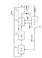
図1に、本発明の実施形態にかかる情報記録再生装置の全体構成を概略的に示す。情報記録再生装置1は、光ディスクDに情報を記録し、また、光ディスクDから情報を再生する。光ディスクDとしては、例えば1回に限り記録が可能なCD−R(Compact Disc-Recordable)、DVD−Rや、複数回にわたって消去及び記録が可能なCD−RW(Compact Disc-Rewritable)、DVD−RWなどの種々の光ディスクを使用することができる。
【0039】
情報記録再生装置1は、光ディスクDに対して記録ビーム及び再生ビームを照射する光ピックアップ2と、光ディスクDの回転を制御するスピンドルモータ3と、光ディスクDへの情報の記録を制御する記録制御部10と、光ディスクに既に記録されている情報の再生を制御する再生制御部20と、スピンドルモータ3の回転を制御するスピンドルサーボ、並びに光ピックアップ2の光ディスクDに対する相対的位置制御であるフォーカスサーボ及びトラッキングサーボを含む各種サーボ制御を行うためのサーボ制御部30と、を備える。
【0040】
記録制御部10は記録信号を受け取り、後述の処理により光ピックアップ2内部のレーザダイオードを駆動するための駆動信号SDを生成して、これを光ピックアップ2へ供給する。
【0041】
再生制御部20は、光ピックアップ2から出力される読取RF信号Srfを受け取り、これに対して所定の復調処理、復号化処理などを施して再生信号を生成して出力する。
【0042】
サーボ制御部30は、光ピックアップ2からの読取RF信号Srfを受け取り、これに基づいてトラッキングエラー信号及びフォーカス信号などのサーボ信号S1を光ピックアップ2へ供給するとともに、スピンドルサーボ信号S2をスピンドルモータ3へ供給する。これにより、トラッキングサーボ、フォーカスサーボ、スピンドルサーボなどの各種サーボ処理が実行される。
【0043】
なお、本発明は主として記録制御部10における記録方法に関するものであり、再生制御及びサーボ制御については既知の種々の方法が適用できるので、それらについての詳細な説明は行わない。
【0044】
また、図1には本発明の1つの実施形態として情報記録再生装置を例示しているが、本発明は記録専用の情報記録装置に適用することも可能である。
【0045】
図2に、光ピックアップ2及び記録制御部10の内部構成を示す。図2に示すように、光ピックアップ2は、光ディスクDに対して情報を記録するための記録ビーム及び光ディスクDから情報を再生するための再生ビームを生成するレーザダイオードLDと、レーザダイオードLDから出射されたレーザ光を受光して、レーザ光に対応するレーザパワーレベル信号LDoutを出力するフロントモニタダイオード(FMD)16とを備える。
【0046】
なお、光ピックアップ2は、この他に再生ビームの光ディスクDによる反射ビームを受光して読取RF信号Srfを生成するための光検出器や、記録ビーム及び再生ビーム並びに反射ビームを適切な方向に案内する光学系などの既知の構成要素を備えるが、それらの図示及び詳細な説明は省略する。
【0047】
一方、記録制御部10は、レーザダイオード(LD)ドライバ12と、APC(Automatic Power Control)回路13と、サンプルホールド(S/H)回路14と、コントローラ15とを備える。
【0048】
LDドライバ12は、記録信号に応じた電流をレーザダイオードLDに供給して、光ディスクDへ情報の記録を行う。フロントモニタダイオード16は、光ピックアップ2内のレーザダイオードLDの近傍に配置され、レーザダイオードLDから出射されるレーザ光を受光して、そのレベルを示すレーザパワーレベル信号LDoutを出力する。
【0049】
サンプルホールド回路14は、サンプルホールド信号APC-S/Hにより規定されるタイミングでレーザパワーレベル信号LDoutのレベルをサンプルし、ホールドする。APC回路13は、サンプルホールド回路14の出力信号に基づき、レーザダイオードLDから出射されるレーザ光のリードパワーレベルが一定となるようにLDドライバ12のパワー制御を行う。
【0050】
コントローラ15は、主として記録動作とAPC動作とを行う。まず、記録動作について説明する。記録動作では、コントローラ15はレーザダイオードLDへ供給される電流量を制御するスイッチの切換信号SWR及びSWWを生成して、LDドライバ12へ供給する。
【0051】
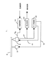
図3にLDドライバ12の詳細構成を示す。図3に示すように、LDドライバ12は、リードレベル用の電流源17R、ライトレベル用の電流源17W、スイッチ18R及び18Wを備える。
【0052】
リードレベル用の電流源17Rは、レーザダイオードLDにリードパワーでレーザ光を出射させるための駆動電流IRを流す電流源であり、駆動電流IRはスイッチ18Rを介してレーザダイオードLDに供給される。よって、スイッチ18RをオンにするとレーザダイオードLDにリードパワーの駆動電流IRが供給され、スイッチ18Rをオフにすると駆動電流IRの供給は停止される。電流源17Rからの電流の大きさは、制御信号SAPCにより変化する。
【0053】
ライトレベル用の電流源17Wは、レーザダイオードLDにライトパワーでレーザ光を出射させるための駆動電流IWを流す電流源であり、駆動電流IWはスイッチ18Wを介してレーザダイオードLDに供給される。よって、スイッチ18Wをオンにすると、レーザダイオードLDにライトパワーの駆動電流IWが供給され、スイッチ18Wをオフにすると駆動電流IWの供給は停止される。
【0054】
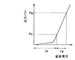
図4に、レーザダイオードLDに供給される駆動電流と、レーザダイオードLDから出射されるレーザ光の出力パワーとの関係を示す。図4からわかるように、レーザダイオードLDに駆動電流IRを供給すると、リードパワーPRでレーザ光が出射される。その状態でさらに駆動電流IWを加えると、ライトパワーPWでレーザ光が出射される。
【0055】
光ディスクへの情報の記録時には、基本的には駆動電流IRを常に供給してリードパワーPRでレーザ光を出射しておき、さらに記録パルスに従って駆動電流IWを追加することによりライトパワーPWが印加されて、情報が光ディスクに記録される。但し、本発明では、以下に詳しく述べるように、ライトパワーの記録パルス列の最後のパルスが印加された後、一時的にスイッチ18Rと18Wの両方を同時にオフにして駆動電流をゼロにして、過渡応答の影響を除去することを特徴とする。
【0056】
次に、APC動作について説明する。APC動作は、レーザダイオードLDにより出力されるレーザ光のリードパワーのレベルが一定となるように、LDドライバ12からレーザダイオードLDに供給される駆動電流レベルを調整するものである。より詳細には、記録信号(8−16変調されており、3T〜11T、14Tの長さのマーク期間及びスペース期間を有する)のスペース部のうち、長いスペース期間(例えば5T〜11T、14Tのスペース期間)中において、リードパワーのレベルが一定となるようにLDドライバ12からの駆動信号SDを調整する。
【0057】
具体的には以下のように動作する。コントローラ15は、上述のように記録信号に対応する記録パルスを生成して、当該記録パルスによってLDドライバ12を駆動してレーザダイオードLDからレーザ光を出射させる。
【0058】
フロントモニタダイオード16は、光ピックアップ2内のレーザダイオードLDの近傍に配置され、レーザダイオードLDから出射したレーザ光を受光してそのレベルを示すレーザパワーレベル信号LDoutを生成し、サンプルホールド回路14に供給する。
【0059】
サンプルホールド回路14は、コントローラ15から入力されるサンプルホールド信号APC-S/Hにより与えられるタイミングで、フロントモニタダイオード16から供給されるレーザパワーレベル信号LDoutをサンプルし、そのレベルを所定期間ホールドする。コントローラ15から出力されるサンプルホールド信号APC-S/Hは、APCを実行する期間を示すパルスであり、具体的には、記録信号中の比較的長いスペース期間(5T〜11T)中の所定期間(APCを実行する期間であり、以下「APC期間」とも呼ぶ。)を示すパルス信号である。
【0060】
よってサンプルホールド回路14は、記録信号のスペース期間中のAPC期間においてレーザパワーレベル信号LDoutのレベルをホールドしてAPC回路13へ供給する。APC回路13は、APC期間におけるレーザパワーレベル信号LDoutのレベルが一定となるように、LDドライバ12へ制御信号SAPCを供給する。
【0061】
制御信号SAPCは、図3に示すように、LDドライバ12内のリードレベル用電流源17Rに入力される。これにより、制御信号SAPCに応じて、リードレベル用電流源17Rから流れる電流IRが変化する。つまり、レーザダイオードLDにより得られるリードパワーレベルが一定となるようにAPCが実行される。
【0062】
[2]第1実施形態
次に、記録制御部10による記録制御の第1実施形態について図5を参照して説明する。図5は、記録制御部10の各部の波形を示すタイミングチャートである。なお、第1実施形態は本発明の記録制御をDVD−Rの記録に適用した例である。
【0063】
図5において、記録信号は8−16変調信号であり、光ディスクの記録面上に形成すべきマークに対応し、マーク期間とスペース期間とを有する。光ディスクの記録面上には、3T〜11T、14Tのいずれかの長さを有するピットが形成されるので、記録信号には3T〜11T、14Tのマーク期間とスペース期間とが含まれる。図5の例では記録信号のうち、長さ6Tのマーク期間、5Tのスペース期間、5Tのマーク期間が示されている。
【0064】
切換信号SWRは図3に示すリードパワー用電流源17Rに接続されたスイッチ18Rを切り換える信号であり、原則としてマーク期間とスペース期間の両方でオンとなっている。マーク期間においては、さらにライトパワー用電流源17Wに接続されたスイッチ18Wを切り換える切換信号SWWは記録パルス列に従って切り換えられる。記録パルス列は、時間幅の長いトップパルス120とそれに続くマルチパルス(「パルストレイン」とも呼ばれる。)121に対応して切り換えられる。そして、パルストレインの最後のパルスが終了したタイミングから所定の期間(パルス122の期間)は、スイッチ18Rと18Wの双方をオフとして、レーザダイオードLDに流れる電流をゼロとする。
【0065】
パルストレインの最後のパルスが終了してからしばらくの期間は、前述のようにパルスの過渡応答により、レーザパワーレベルがリードパワーレベルより高い期間が生じるが、このように、パルストレインの最後のパルスの終了後一定期間はリードパワーもオフとして(以下、この期間を「レーザオフ期間」と呼ぶ。)、レーザダイオードLDの電流をゼロとすることにより、過渡応答により生じるレーザパワーレベルの上昇を吸収することができる。
【0066】
図5に示すレーザパワーレベル信号Loutの波形はこの様子を示している。即ち、最初の6Tのマーク期間内においては、まず継続的にリードパワーPRが印加されており、それにライトパワーPWの振幅を有するトップパルス120及び3つのパルスによるパルストレイン121が印加される。これにより光ディスクの記録面上に長さ6Tの記録マークが形成される。
【0067】
そして、6Tのマーク期間に続くスペース期間では、パルストレイン121の最後のパルスの終了後のレーザオフ期間中122においては、ライトパワーのみならずリードパワーもオフとなり、その結果、レーザパワーレベル信号LDoutはゼロレベルLDoffまで落ちる。そして、レーザオフ期間122が終わると、レーザパワーレベル信号LDoutはリードパワーレベルPRに上昇する。
【0068】
図5の右側の5Tのマーク期間においても、同様にレーザオフ期間122が設けられている(但し、5Tマーク期間であるので、パルストレイン121が2つのパルスにより構成されている)。
【0069】
このように、全てのマーク期間の終了後、即ち、マーク期間中の最後の記録パルス直後に一定のレーザオフ期間を設けることにより、マーク期間終了後の過渡応答の影響を除去することができる。
【0070】
レーザオフ期間の時間幅は可変とすることができ、例えば1T〜2Tの間の任意の長さに設定することができる。但し、レーザオフ期間の時間幅にはAPCとの関係で制限がある。前述のように、例えば5T以上の長いスペース期間においては、APC期間が設定され、レーザパワーレベル信号LDoutがサンプルホールド回路14によりサンプルホールドされて、そのレベルを維持するようにAPCが行われるので、APC期間中にはレーザパワーレベル信号LDoutはリードパワーレベルになければならず、その間にレーザをオフとするとAPCに支障が出てしまう。
【0071】
よって、レーザオフ期間122は、APC期間(即ち、サンプルホールド信号APC-S/Hがローレベルの期間)と重複することはできない。通常、APC期間は、5T〜11Tのスペース期間中の前後の1〜2Tの期間をマージンとして除外し、残りの期間に設定される。よって、スペース期間の先頭における1〜2Tのマージン以内であればレーザをオフにしてもAPCに支障が生じることはない。このことより、APCが実行されるスペース期間では、レーザオフ期間はマーク期間の終了後、APC期間の開始前に設定するのが好ましい。実際には、上述のように、スペース期間の先頭に設けられる1T〜2Tのマージン中にレーザオフ期間を設定することが好ましい。
【0072】
図6に実際のレーザ光の波形例を示す。図6(a)は比較のために用意した、レーザオフ期間を設けない場合のレーザパワーレベル信号LDoutの波形であり、図6(b)は本願の方法(レーザオフ期間を設けた)のレーザパワーレベル信号LDoutの波形である。図6(a)に示すように、レーザオフ期間を設けない場合は、パルストレインの最後のパルスの後に過渡応答が発生してレーザパワーレベルが高くなっている(符号130の部分を参照)。これに対して、図6(b)に示すように、レーザオフ期間を設けた場合は、パルストレインの最後のパルスの後にレーザパワーレベル信号LDoutが一旦ゼロレベルまで落ちる(符号131の部分参照)。よって、光ディスクの記録面上の残留熱は小さく、後続のマーク期間におけるマーク形成に熱干渉による悪影響を及ぼすことが防止できる。
【0073】
図7は、レーザオフ期間を設けた場合と設けない場合に、光ディスクに実験的に形成した記録マークの読取RF信号波形を示す。図7(a)はレーザオフ期間を設けた場合であり、3Tマーク、4Tマーク、5Tマーク、6Tマークの読取RF信号のエンベロープ波形は明確な輪郭を有している。
【0074】
一方、図7(b)及び7(c)は、レーザオフ期間を設けない場合のエンベロープ波形であり、パルスの過渡応答による熱干渉が後続のマーク形成に影響を与えている。図7(b)の場合は、各エンベロープ波形の輪郭がぼやけて太くなっており、図7(c)の場合はさらに各エンベロープ波形が2つに枝分かれしたように見える。このような現象は、熱干渉により記録マークが不適切に変形していることに起因している。
【0075】
このように、本発明によれば、マーク期間の後にレーザオフ期間を設けることにより、記録パルスの過渡応答による熱干渉の影響を排除し、正しい記録マークを形成することが可能となる。
【0076】
[3]第2実施形態
次に、本発明の第2実施形態について説明する。上述の第1実施形態においては、マーク期間後の全てのスペース期間中にレーザオフ期間を設けているが、第2実施形態においては、短いスペース期間(例えば3T及び4Tのスペース期間)のみでレーザオフ期間を設け、長いスペース期間(例えば5T以上のスペース期間)ではレーザオフ期間を設けないこととする。なお、第2実施形態も本発明の記録制御をDVD−Rの記録に適用した例である。
【0077】
レーザオフ期間は、前述のように記録パルスの終了後の過渡応答によりレーザパワーレベルが増加してしまうことによる影響を除去する目的で設けられるが、マーク期間に続くスペース期間が長い場合には、次のマーク期間までに時間的余裕があるので、過渡応答の影響は次のマーク期間には比較的及びにくい。これに対し、マーク期間に続くスペース期間が短い場合には、次のマーク期間までの時間が短いので、過渡応答によるレベル増加分の残留熱が次のマーク期間における記録マーク形成に悪影響を及ぼす確率が高くなる。
【0078】
このような理由から、短いスペース期間のみにおいてレーザオフ期間を設けることによっても、過渡応答により次のマーク期間のマーク形成に与える悪影響を排除することが可能である。
【0079】
この場合、レーザオフ期間は第1の実施形態の場合より長く設定することができる。先に述べたように、5T〜11T、14Tの長いスペース期間には、APCのためにレーザパワーレベル信号LDoutをサンプルホールドするAPC期間が設定される。このため、レーザオフ期間がAPC期間と重複してはならず、レーザオフ期間の時間幅は実質的に1T〜2T程度の長さに限られていた。
【0080】
これに対し、第2の実施形態では、短いスペース期間(3T又は4Tのスペース期間)においてのみレーザオフ期間が設定され、しかも短いスペース期間中にはAPC期間は設定されないので、レーザオフ期間を長く設定することができる。
【0081】
これを図8を参照して説明する。図8は第2実施形態における記録制御部10の各部の波形を示し、6Tのマーク期間後に3Tのスペース期間があり、さらに5Tのマーク期間が続いている。3Tのスペース期間中にはAPC期間は設定されないためサンプルホールド信号APC-S/Hはハイレベルのままであり、レーザパワーレベル信号LDoutのサンプルホールドは行われない。よって、6Tのマーク期間の終了後の3Tのスペース期間中において、レーザオフ期間122は十分に長く設定されている。これにより光ディスクの情報記録面上の残留熱は減少し、記録パルスの過渡応答の影響が次のマーク期間に及ぶことを効果的に防止することができる。
【0082】
なお、この意味では、第2実施形態は、APCが行われないスペース期間にのみレーザオフ期間を設定する方法であるということもできる。
【0083】
また、第1実施形態と第2実施形態とを組み合わせることもできる。即ち、第1実施形態のようにレーザオフ期間を全てのマーク期間に設けることとし、かつ、第2実施形態のように短いスペース期間においてはレーザオフ期間を長く設定することができる。これによれば、短いスペースの場合にはレーザオフ期間が長くなるので、熱干渉を効果的に防止することができる。
【0084】
[4]第3実施形態
次に、本発明の第3実施形態について説明する。上述の第1及び第2実施形態は、本発明をDVD−Rに適用した例であったが、第3実施形態は本発明をDVD−RWに適用した例である。図10に、DVD−RWへの記録における記録制御部10の各部の波形図を示す。DVD−RWでは、基本的にDVD−Rと同様の方法により記録マークが形成されるが、記録動作に先行して消去動作が実行されるので、図10のレーザパワーレベル信号LDoutに示すように、通常はレーザダイオードLDからのレーザパワーは消去レベルPEにある。よって、APCも、長いスペース期間中に設定されるAPC期間において消去レベルPEをサンプルホールドすることにより行われる。
【0085】
記録パルス列はDVD−Rの場合と同様に、トップパルス120とパルストレイン121から構成される。そして、パルストレイン121の終了後に、レーザオフ期間122を設け、レーザパワーレベルを一時的にゼロレベルLDoffまで落とす。その後、レーザパワーレベルは定常状態である消去レベルPEに戻る。
【0086】
このように、DVD−RWの場合も、記録パルスの終了後にレーザオフ期間を設けることにより、過渡応答による熱干渉の影響を除去することができる。
【0087】
なお、DVD−RWの場合は、レーザオフ期間の時間幅は消去動作に影響を与えない範囲に限定される。即ち、レーザオフ期間中はレーザパワーレベルが消去レベルに至っていないため、DVD−RW上に既に記録されている情報の消去が行えないことになる。よって、レーザオフ期間を長くしすぎると、既に記録されている情報の消去を行えず、情報の消し残りが生じてしまうという不具合がある。よって、レーザオフ期間の時間幅は情報の消去に影響を与えない、比較的短い期間に限定される。実際には、DVD−RWの場合は、記録パルス終了後に一旦レーザパワーレベルをリードレベルまで落とす期間(「クールパルス期間」と呼ばれる。図9の破線140を参照)が設けられる。よって、1つの好適な方法として、クールパルス期間内においてレーザオフ期間を設ければ、消し残りなどの問題を生じることがない。
【0088】
[5]変形例
上述のレーザオフ期間では、レーザパワーレベルが完全にゼロレベルとなるように、レーザダイオードLDに与える電流値をゼロとしていた。しかし、レーザパワーレベルを完全にゼロレベルとしなくても、リードパワーレベルより低いレベルに設定すれば、その分だけディスクへの残留熱は低下するので、熱干渉の影響を減らす効果を得ることができる。
【0089】
また、上記の実施形態では、マーク期間中の最後のパルス終了後にレーザオフ期間を開始しているが、理論的には次のマーク期間が到来する前であれば、スペース期間中のどこかにレーザオフ期間を設けることにより、次の記録マーク形成への熱干渉を低下させることができる。特に、APC期間が設定されないスペース期間においては十分な時間幅のレーザオフ期間を設定できるので、レーザオフ期間は必ずしもマーク期間終了直後から開始しなくてもよい。
【0090】
【発明の効果】
以上説明したように、本発明によれば、マーク期間の終了後のスペース期間中において、一時的にレーザパワーをゼロレベル付近まで落とすレーザオフ期間を設けたので、記録パルスの過渡応答によるレーザパワーレベル(バイアスレベル)の上昇を緩和し、熱干渉による次の記録マーク形成への悪影響を防止することができる。これは、特に記録速度が高速化した場合にも好ましい形状の記録マークを形成できるという点で有効である。
【図面の簡単な説明】
【図1】本発明を適用した情報記録再生装置の概略構成を示すブロック図である。
【図2】図1に示す記録制御部の構成を示すブロック図である。
【図3】図2に示すLDドライバの構成を示す図である。
【図4】レーザダイオードに与えられる駆動電流と出力パワーとの関係を示すグラフである。
【図5】本発明の第1実施形態による記録制御時の記録制御部各部の波形を示すタイミングチャートである。
【図6】レーザオフ期間を含むレーザ出力レベルを示す波形図である。
【図7】記録マークの読取RF信号の波形図である。
【図8】本発明の第2実施形態による記録制御時の記録制御部各部の波形を示すタイミングチャートである。
【図9】本発明の第3実施形態による記録制御時の記録制御部各部の波形を示すタイミングチャートである。
【符号の説明】
1 情報記録再生装置
2 光ピックアップ
3 スピンドルモータ
10 記録制御部
12 LDドライバ
13 APC回路
14 サンプルホールド回路
15 コントローラ
16 フロントモニタダイオード
17R、17W 電流源
18R、18W スイッチ
20 再生制御部
30 サーボ制御部[0001]
BACKGROUND OF THE INVENTION
The present invention belongs to a technique for recording information on an optical disk using a laser beam or the like.
[0002]
[Prior art]
In a writable or rewritable optical disc such as a DVD-R (DVD-Recordable) and a DVD-RW (DVD-Re-recordable), information is recorded by irradiating a laser beam on the recording surface of the disc. In the portion irradiated with the laser beam on the recording surface of the optical disc, the temperature rises, so that the optical recording medium constituting the optical disc changes, whereby a recording mark is formed on the recording surface.
[0003]
Therefore, the laser beam is modulated with a recording pulse having a time width corresponding to the information to be recorded, and a laser pulse having a length corresponding to the signal to be recorded is generated. A recording mark having a length corresponding to the information can be formed on the optical disc.
[0004]
On the other hand, recently, a method of forming a recording mark by a pulse train including a plurality of short pulses is used instead of forming one recording mark by one laser pulse. Such a method is also called a write strategy, and heat accumulation on the recording surface of the optical disk is reduced compared to a method of irradiating a single recording pulse, so the temperature distribution on the recording surface on which the recording mark is formed is reduced. It can be made uniform. As a result, it is possible to prevent the recording mark from having a teardrop shape and form a recording mark having a preferable shape.
[0005]
The recording pulse train is composed of a plurality of pulses whose amplitude varies between a predetermined read power level and a write power level. That is, an optical disk on which a recording mark is to be formed by irradiating the recording surface with laser light with read power in an area on the recording surface (hereinafter also referred to as a “space part”) of an optical disk that does not form a recording mark in accordance with a recording signal. In the area on the recording surface (hereinafter also referred to as “mark part”), the recording surface is irradiated with laser light with a power corresponding to a recording pulse train whose amplitude changes between the read power and the write power. A recording mark is formed on the recording surface.
[0006]
[Problems to be solved by the invention]
However, when the recording surface of the optical disk is irradiated with a laser pulse corresponding to the recording pulse, the laser irradiation level (bias level) after irradiation of the recording pulse increases due to the transient response of the pulse. The amplitude of the recording pulse varies between the read power and the write power, and theoretically, the laser irradiation level returns instantaneously to the read power after the end of the recording pulse. However, in reality, at the end of the recording pulse, the laser irradiation level instantaneously changes from write power to read power, so a transient response of the recording pulse occurs, and the laser irradiation level does not instantaneously return to read power, but rather The laser irradiation level increases for a certain period. As a result, a period in which the laser irradiation level is higher than the read power level is generated for a short time after the end of the recording pulse. This may affect the formation of the next recording mark as thermal interference. In particular, when the space period until the next recording mark is short, there is a case where the next recording mark cannot be correctly formed due to the residual heat due to the transient response described above when the next recording mark is formed.
[0007]
This effect is particularly noticeable when the recording speed is increased, that is, when high-speed recording is performed on the optical disk. In the case of normal speed (low speed) recording, a certain amount of time until the mark period corresponding to the next recording mark can be secured, so the influence of the transient response is mitigated, but the recording speed is twice or three times the normal speed. If the speed is increased, the time interval of the recording pulse train is shortened, so that the next recording pulse train arrives with the residual heat remaining, and the residual heat due to the above transient response is heated to the next recording mark. The possibility of influence as interference increases.
[0008]
Furthermore, when the recording speed is increased, it is necessary to increase the recording power in accordance with the increase in the recording speed in order to correctly form the recording mark. For this reason, the increase in laser irradiation level due to the transient response is increased, and the adverse effect is increased.
[0009]
Since the increase in the laser irradiation level due to the transient response of the recording pulse as described above occurs after the recording pulse is applied, that is, in the space period of the recording signal, the recording mark is adjusted by adjusting the pulse width of the recording pulse. This effect cannot be eliminated by the light strategy technology that adjusts the shape.
[0010]
The present invention has been made in view of the above points, and provides an information recording apparatus and method capable of forming a correct recording mark by eliminating the influence of a transient response of a recording pulse train even during high-speed recording. The task is to do.
[0011]
[Means for Solving the Problems]
In one aspect of the present invention, in an information recording apparatus that irradiates a recording medium with laser light to form a recording mark corresponding to a recording signal, the light source that emits the laser light, and the light source based on the recording signal Control means for irradiating the recording medium with a laser pulse by driving the recording medium, the control means corresponding to the recording signal the output level of the laser pulse during the mark period of the recording signal. Mark control means for changing between a normal level and a writing level higher than the normal level, and at least some of the recording signalsTime widthSpace control means for changing the output level of the laser pulse to a level lower than the normal level over a predetermined period during the space period, and the space control means has a predetermined first time in a space period having a long time width. The output level of the laser pulse is changed to the low level over one period, and the output level of the laser pulse is changed to the low level over a second period longer than the first period in a space period with a short time width.
[0012]
According to the information recording apparatus described above, the recording medium is irradiated with the laser pulse corresponding to the recording signal by driving the light source with the pulse signal corresponding to the recording signal. The recording signal has a mark period in which a recording mark is formed and a space period in which no recording mark is formed. During the mark period, the output level of the laser pulse changes between the normal level and the writing level, whereby a recording mark is formed on the recording medium. On the other hand, the laser pulse output level is changed to a level lower than the normal level over a predetermined period in the space period. Thereby, heat accumulation in the recording medium due to the transient response of the laser pulse during the mark period is reduced, and a correct recording mark can be formed in the subsequent mark period.Further, in a short space period, the transient response of the laser pulse during the previous mark period tends to affect the next mark period, so the output level of the laser pulse is lowered over a longer period.
[0013]
In one aspect of the information recording apparatus, a level lower than the normal level is set to a zero level.
[0014]
According to this aspect, since the level of the laser pulse temporarily becomes zero during the space period, the heat accumulation on the recording medium is sufficiently reduced during that time.
[0018]
In still another aspect of the information recording apparatus, the space control meansTime widthDuring the space period, the output level of the laser pulse is changed to a level lower than the normal level.
[0019]
According to this aspect, allTime widthSince the output level of the laser pulse is lowered during the space period, the influence of thermal interference due to the transient response of the laser pulse during the mark period can be effectively eliminated.
[0022]
In still another aspect of the information recording apparatus, the space period with a short time width may be a 3T or 4T space period, and the space period with a long time width may be a space period of 5T or more.
[0029]
In still another aspect of the information recording apparatus, the recording medium may be a recording medium that can be recorded only once, and the normal level may be a reading level.
[0030]
According to this aspect, the present invention can be applied to recording media such as CD-R and DVD-R.
[0031]
In still another aspect of the information recording apparatus, the recording medium may be a recording medium that can be written and erased a plurality of times, and the normal level may be an erasure level.
[0032]
According to this aspect, the present invention can be applied to a recording medium such as a CD-RW or a DVD-RW.
[0033]
In still another aspect of the information recording apparatus, the space control unit changes the output level of the laser pulse to a level lower than the normal level from the beginning of the space period.
[0034]
According to this aspect, since the output level of the laser pulse is lowered from the beginning of the space period, the influence of the transient response is efficiently eliminated by reducing the laser power immediately after the end of the mark period during which the writing level laser pulse is irradiated. be able to.
[0035]
In another aspect of the present invention, in an information recording method for irradiating a recording medium with laser light to form a recording mark according to a recording signal, the step of emitting the laser light, and a light source based on the recording signal Irradiating the recording medium with a laser pulse by driving, wherein the step of irradiating the laser pulse records an output level of the laser pulse during a mark period of the recording signal. Corresponding to the signal, changing between a normal level and a writing level higher than the normal level, and at least some of the recording signalsTime widthA space control step for changing the output level of the laser pulse to a level lower than the normal level over a predetermined period during the space period, and the space control step has a predetermined time period in a space period having a long time width. The output level of the laser pulse is changed to the low level over a first period, and the output level of the laser pulse is changed to the low level over a second period longer than the first period in a space period with a short time width. .
[0036]
According to the above information recording method, the recording medium is irradiated with the laser pulse corresponding to the recording signal by driving the light source with the pulse signal corresponding to the recording signal. The recording signal has a mark period for forming a recording mark and a space period during which no recording mark is formed. During the mark period, the output level of the laser pulse changes between the normal level and the writing level, whereby a recording mark is formed on the recording medium. On the other hand, the laser pulse output level is changed to a level lower than the normal level over a predetermined period in the space period. Thereby, heat accumulation in the recording medium due to the transient response of the laser pulse during the mark period is reduced, and a correct recording mark can be formed in the subsequent mark period.Further, in a short space period, the transient response of the laser pulse during the previous mark period tends to affect the next mark period, so the output level of the laser pulse is lowered over a longer period.
[0037]
DETAILED DESCRIPTION OF THE INVENTION
Preferred embodiments of the present invention will be described below with reference to the drawings.
[0038]
[1] Device configuration
FIG. 1 schematically shows the overall configuration of an information recording / reproducing apparatus according to an embodiment of the present invention. The information recording / reproducing
[0039]
An information recording / reproducing
[0040]
The
[0041]
The
[0042]
The
[0043]
Note that the present invention mainly relates to a recording method in the
[0044]
FIG. 1 illustrates an information recording / reproducing apparatus as one embodiment of the present invention, but the present invention can also be applied to a recording-only information recording apparatus.
[0045]
FIG. 2 shows the internal configuration of the
[0046]
In addition, the
[0047]
On the other hand, the
[0048]
The
[0049]
The
[0050]
The
[0051]
FIG. 3 shows a detailed configuration of the
[0052]
The read level
[0053]
The
[0054]
FIG. 4 shows the relationship between the drive current supplied to the laser diode LD and the output power of the laser light emitted from the laser diode LD. As can be seen from FIG. 4, the drive current I is applied to the laser diode LD.RLead power PRA laser beam is emitted. In this state, the drive current IW, Light power PWA laser beam is emitted.
[0055]
When recording information on the optical disc, basically, the drive current IRAlways supply lead power PRThe laser beam is emitted with a drive current I according to the recording pulse.WWrite power P by addingWIs applied to record information on the optical disk. However, in the present invention, as will be described in detail below, after the last pulse of the write pulse of the write power is applied, both the
[0056]
Next, the APC operation will be described. The APC operation is to adjust the drive current level supplied from the
[0057]
Specifically, it operates as follows. The
[0058]
The
[0059]
The
[0060]
Therefore, the
[0061]
Control signal SAPC3 is input to a read level
[0062]
[2] First embodiment
Next, a first embodiment of recording control by the
[0063]
In FIG. 5, the recording signal is an 8-16 modulation signal and corresponds to a mark to be formed on the recording surface of the optical disc, and has a mark period and a space period. Since a pit having a length of 3T to 11T or 14T is formed on the recording surface of the optical disc, the recording signal includes a mark period and a space period of 3T to 11T and 14T. In the example of FIG. 5, a 6T mark period, a 5T space period, and a 5T mark period are shown in the recording signal.
[0064]
Switching signal SWRIs a signal for switching the
[0065]
For a period of time after the last pulse of the pulse train ends, as described above, due to the transient response of the pulse, a period in which the laser power level is higher than the read power level occurs, but in this way, the last pulse of the pulse train The read power is also turned off for a certain period after the end of this step (hereinafter, this period is referred to as a “laser off period”), and the laser diode LD current is made zero to absorb the increase in the laser power level caused by the transient response. be able to.
[0066]
The waveform of the laser power level signal Lout shown in FIG. 5 shows this state. That is, in the first 6T mark period, first, the read power P is continuously increased.RIs applied to the light power PWAnd a
[0067]
In the space period following the 6T mark period, not only the write power but also the read power is turned off during the laser off
[0068]
In the 5T mark period on the right side of FIG. 5, a laser off
[0069]
Thus, by providing a constant laser off period after the end of all the mark periods, that is, immediately after the last recording pulse in the mark period, it is possible to eliminate the influence of the transient response after the end of the mark period.
[0070]
The time width of the laser off period can be made variable, for example, can be set to an arbitrary length between 1T and 2T. However, the time width of the laser off period is limited in relation to APC. As described above, for example, in a long space period of 5T or more, an APC period is set, and the laser power level signal LDout is sampled and held by the sample and hold
[0071]
Therefore, the laser off
[0072]
FIG. 6 shows an example of the actual laser beam waveform. FIG. 6A shows a waveform of a laser power level signal LDout prepared for comparison when no laser off period is provided, and FIG. 6B shows a laser power level of the method of the present application (provided with a laser off period). It is a waveform of the signal LDout. As shown in FIG. 6A, when the laser off period is not provided, a transient response occurs after the last pulse of the pulse train, and the laser power level is high (see reference numeral 130). On the other hand, as shown in FIG. 6B, when the laser off period is provided, the laser power level signal LDout once falls to the zero level after the last pulse of the pulse train (see the part 131). Therefore, the residual heat on the recording surface of the optical disk is small, and it is possible to prevent adverse effects due to thermal interference on the mark formation in the subsequent mark period.
[0073]
FIG. 7 shows the read RF signal waveform of the recording mark experimentally formed on the optical disc with and without the laser off period. FIG. 7A shows a case where a laser off period is provided, and the envelope waveforms of the read RF signals of the 3T mark, 4T mark, 5T mark, and 6T mark have a clear outline.
[0074]
On the other hand, FIGS. 7B and 7C are envelope waveforms when no laser off period is provided, and thermal interference due to the transient response of the pulse affects subsequent mark formation. In the case of FIG. 7B, the contour of each envelope waveform is blurred and thick, and in the case of FIG. 7C, each envelope waveform appears to be further branched into two. Such a phenomenon is caused by an inappropriate deformation of the recording mark due to thermal interference.
[0075]
Thus, according to the present invention, by providing the laser off period after the mark period, it is possible to eliminate the influence of thermal interference due to the transient response of the recording pulse and form a correct recording mark.
[0076]
[3] Second embodiment
Next, a second embodiment of the present invention will be described. In the first embodiment described above, the laser off period is provided in all the space periods after the mark period. However, in the second embodiment, the laser off period is only a short space period (for example, 3T and 4T space periods). The laser off period is not provided in a long space period (for example, a space period of 5T or more). The second embodiment is also an example in which the recording control of the present invention is applied to recording on a DVD-R.
[0077]
The laser off period is provided for the purpose of removing the influence of the increase in the laser power level due to the transient response after the end of the recording pulse as described above, but when the space period following the mark period is long, Since there is a time margin before the next mark period, the influence of the transient response is relatively difficult to reach the next mark period. On the other hand, when the space period following the mark period is short, the time until the next mark period is short, and therefore the probability that the residual heat due to the level increase due to the transient response adversely affects the recording mark formation in the next mark period. Becomes higher.
[0078]
For this reason, even if the laser off period is provided only in a short space period, it is possible to eliminate the adverse effect on the mark formation in the next mark period due to the transient response.
[0079]
In this case, the laser off period can be set longer than that in the first embodiment. As described above, in the long space period of 5T to 11T and 14T, the APC period for sample-holding the laser power level signal LDout for APC is set. For this reason, the laser off period must not overlap with the APC period, and the time width of the laser off period is substantially limited to a length of about 1T to 2T.
[0080]
On the other hand, in the second embodiment, the laser off period is set only in a short space period (3T or 4T space period), and the APC period is not set in the short space period, so the laser off period is set long. be able to.
[0081]
This will be described with reference to FIG. FIG. 8 shows the waveform of each part of the
[0082]
In this sense, it can also be said that the second embodiment is a method of setting the laser off period only in the space period in which APC is not performed.
[0083]
Also, the first embodiment and the second embodiment can be combined. That is, the laser off period is provided in all mark periods as in the first embodiment, and the laser off period can be set longer in a short space period as in the second embodiment. According to this, in the case of a short space, the laser off period becomes long, so that thermal interference can be effectively prevented.
[0084]
[4] Third embodiment
Next, a third embodiment of the present invention will be described. Although the first and second embodiments described above are examples in which the present invention is applied to a DVD-R, the third embodiment is an example in which the present invention is applied to a DVD-RW. FIG. 10 is a waveform diagram of each part of the
[0085]
The recording pulse train is composed of a
[0086]
Thus, also in the case of DVD-RW, the effect of thermal interference due to transient response can be eliminated by providing the laser off period after the end of the recording pulse.
[0087]
In the case of DVD-RW, the time width of the laser off period is limited to a range that does not affect the erase operation. That is, since the laser power level does not reach the erasure level during the laser off period, information already recorded on the DVD-RW cannot be erased. Therefore, if the laser off period is too long, there is a problem that information that has already been recorded cannot be erased and information remains unerased. Therefore, the time width of the laser off period is limited to a relatively short period that does not affect the erasure of information. Actually, in the case of DVD-RW, a period (called a “cool pulse period”, which is referred to as a
[0088]
[5] Modification
In the laser off period described above, the current value applied to the laser diode LD is set to zero so that the laser power level is completely zero. However, even if the laser power level is not completely zero, if the laser power level is set to a level lower than the read power level, the residual heat to the disk will be reduced by that amount, so the effect of reducing the influence of thermal interference can be obtained. it can.
[0089]
In the above embodiment, the laser off period is started after the end of the last pulse in the mark period. Theoretically, if the next mark period is before the laser off period, the laser off period is somewhere in the space period. By providing the period, thermal interference with the next recording mark formation can be reduced. In particular, in the space period in which the APC period is not set, a laser off period having a sufficient time width can be set, so that the laser off period does not necessarily start immediately after the end of the mark period.
[0090]
【The invention's effect】
As described above, according to the present invention, in the space period after the end of the mark period, the laser off period in which the laser power is temporarily reduced to near the zero level is provided. The increase in (bias level) can be mitigated, and adverse effects on the next recording mark formation due to thermal interference can be prevented. This is effective in that a recording mark having a preferable shape can be formed even when the recording speed is increased.
[Brief description of the drawings]
FIG. 1 is a block diagram showing a schematic configuration of an information recording / reproducing apparatus to which the present invention is applied.
FIG. 2 is a block diagram illustrating a configuration of a recording control unit illustrated in FIG.
FIG. 3 is a diagram showing a configuration of an LD driver shown in FIG. 2;
FIG. 4 is a graph showing the relationship between drive current applied to a laser diode and output power.
FIG. 5 is a timing chart showing waveforms of respective parts of the recording control unit during recording control according to the first embodiment of the present invention.
FIG. 6 is a waveform diagram showing a laser output level including a laser off period.
FIG. 7 is a waveform diagram of a read RF signal of a recording mark.
FIG. 8 is a timing chart showing waveforms of respective parts of the recording control unit during recording control according to the second embodiment of the present invention.
FIG. 9 is a timing chart showing waveforms of respective parts of the recording control unit during recording control according to the third embodiment of the present invention.
[Explanation of symbols]
1 Information recording and playback device
2 Optical pickup
3 Spindle motor
10 Recording control unit
12 LD driver
13 APC circuit
14 Sample hold circuit
15 Controller
16 Front monitor diode
17R, 17W current source
18R, 18W switch
20 Playback control unit
30 Servo controller
Claims (8)
前記レーザ光を出射する光源と、
前記記録信号に基づいて前記光源を駆動することにより、前記記録媒体上にレーザパルスを照射する制御手段と、を備え、
前記制御手段は、
前記記録信号のマーク期間中には、前記レーザパルスの出力レベルを、記録信号に対応して、通常レベルと、前記通常レベルよりも高い書込レベルとの間で変化させるマーク制御手段と、
前記記録信号の少なくともいくつかの時間幅のスペース期間中に、所定期間にわたって、前記レーザパルスの出力レベルを前記通常レベルより低いレベルに変化させるスペース制御手段と、備え、
前記スペース制御手段は、時間幅が長いスペース期間においては所定の第1期間にわたって前記レーザパルスの出力レベルを前記低いレベルに変化させ、時間幅が短いスペース期間においては、前記第1期間より長い第2期間にわたって前記レーザパルスの出力レベルを前記低いレベルに変化させることを特徴とする情報記録装置。In an information recording apparatus for irradiating a recording medium with laser light to form a recording mark according to a recording signal,
A light source for emitting the laser light;
Control means for irradiating a laser pulse on the recording medium by driving the light source based on the recording signal,
The control means includes
Mark control means for changing the output level of the laser pulse between a normal level and a writing level higher than the normal level in accordance with the recording signal during the mark period of the recording signal;
Space control means for changing the output level of the laser pulse to a level lower than the normal level over a predetermined period during a space period of at least some time widths of the recording signal;
The space control means changes the output level of the laser pulse to the low level over a predetermined first period in a space period with a long time width, and in the space period with a short time width, the first time period longer than the first period. An information recording apparatus, wherein the output level of the laser pulse is changed to the low level over two periods.
前記レーザ光を出射するステップと、
前記記録信号に基づいて光源を駆動することにより、前記記録媒体上にレーザパルスを照射するステップと、を有し、
前記レーザパルスを照射するステップは、
前記記録信号のマーク期間中には、前記レーザパルスの出力レベルを、記録信号に対応して、通常レベルと、前記通常レベルよりも高い書込レベルとの間で変化させるステップと、
前記記録信号の少なくともいくつかの時間幅のスペース期間中に、所定期間にわたって、前記レーザパルスの出力レベルを、前記通常レベルより低いレベルに変化させるスペース制御ステップと、有し、
前記スペース制御ステップは、時間幅が長いスペース期間においては所定の第1期間にわたって前記レーザパルスの出力レベルを前記低いレベルに変化させ、時間幅が短いスペース期間においては、前記第1期間より長い第2期間にわたって前記レーザパルスの出力レベルを前記低いレベルに変化させることを特徴とする情報記録方法。In an information recording method of irradiating a recording medium with laser light to form a recording mark according to a recording signal,
Emitting the laser beam;
Irradiating a laser pulse on the recording medium by driving a light source based on the recording signal,
The step of irradiating the laser pulse includes:
During the mark period of the recording signal, changing the output level of the laser pulse between a normal level and a writing level higher than the normal level corresponding to the recording signal;
A space control step of changing the output level of the laser pulse to a level lower than the normal level over a predetermined period during a space period of at least some time widths of the recording signal;
The space control step changes the output level of the laser pulse to the low level over a predetermined first period in a space period having a long time width, and is longer than the first period in a space period having a short time width. An information recording method, wherein the output level of the laser pulse is changed to the low level over two periods.
Priority Applications (6)
| Application Number | Priority Date | Filing Date | Title |
|---|---|---|---|
| JP2001266460A JP4405115B2 (en) | 2001-09-03 | 2001-09-03 | Information recording apparatus and information recording method |
| DE60227621T DE60227621D1 (en) | 2001-09-03 | 2002-08-30 | Information recording apparatus and information recording method |
| EP02256026A EP1288923B1 (en) | 2001-09-03 | 2002-08-30 | Information recording apparatus and information recording method |
| AT02256026T ATE401646T1 (en) | 2001-09-03 | 2002-08-30 | INFORMATION RECORDING APPARATUS AND INFORMATION RECORDING METHOD |
| US10/231,130 US20030048724A1 (en) | 2001-09-03 | 2002-08-30 | Information recording apparatus and information recording method |
| US12/100,463 US7965602B2 (en) | 2001-09-03 | 2008-04-10 | Information recording apparatus and information recording method |
Applications Claiming Priority (1)
| Application Number | Priority Date | Filing Date | Title |
|---|---|---|---|
| JP2001266460A JP4405115B2 (en) | 2001-09-03 | 2001-09-03 | Information recording apparatus and information recording method |
Publications (2)
| Publication Number | Publication Date |
|---|---|
| JP2003077128A JP2003077128A (en) | 2003-03-14 |
| JP4405115B2 true JP4405115B2 (en) | 2010-01-27 |
Family
ID=19092745
Family Applications (1)
| Application Number | Title | Priority Date | Filing Date |
|---|---|---|---|
| JP2001266460A Expired - Fee Related JP4405115B2 (en) | 2001-09-03 | 2001-09-03 | Information recording apparatus and information recording method |
Country Status (5)
| Country | Link |
|---|---|
| US (2) | US20030048724A1 (en) |
| EP (1) | EP1288923B1 (en) |
| JP (1) | JP4405115B2 (en) |
| AT (1) | ATE401646T1 (en) |
| DE (1) | DE60227621D1 (en) |
Families Citing this family (7)
| Publication number | Priority date | Publication date | Assignee | Title |
|---|---|---|---|---|
| CN100401400C (en) * | 2002-02-15 | 2008-07-09 | 索尼株式会社 | Rewritable optical information recording medium and recording/reproducing method, recording/reproducing device |
| WO2003105009A1 (en) * | 2002-06-07 | 2003-12-18 | Bellsouth Intellectual Property Corporation | Sytems and methods for establishing electronic conferencing over a distributed network |
| TW200509104A (en) * | 2003-05-23 | 2005-03-01 | Matsushita Electric Ind Co Ltd | Information recording medium; recording device, method and program thereof |
| WO2005041175A1 (en) * | 2003-10-27 | 2005-05-06 | Pioneer Corporation | Information recording device and information recording method |
| JP4754170B2 (en) * | 2003-12-03 | 2011-08-24 | パナソニック株式会社 | Laser drive circuit and optical communication device |
| WO2005096277A1 (en) | 2004-03-31 | 2005-10-13 | Pioneer Corporation | Information recording apparatus, information recording method, and information recording program |
| CN1938763A (en) | 2004-03-31 | 2007-03-28 | 日本先锋公司 | Information recording device, information recording method, and information recording program |
Family Cites Families (15)
| Publication number | Priority date | Publication date | Assignee | Title |
|---|---|---|---|---|
| JP2684657B2 (en) * | 1987-11-13 | 1997-12-03 | ヤマハ株式会社 | Optical disk recording method |
| US5590111A (en) * | 1990-06-29 | 1996-12-31 | Hitachi, Ltd. | Method of controlling recording of optical records |
| JP3259204B2 (en) * | 1992-10-21 | 2002-02-25 | 株式会社ニコン | Optical recording method and method for determining pulse train conditions for optical recording |
| JPH06150319A (en) | 1992-10-30 | 1994-05-31 | Hitachi Ltd | Recording control system for information |
| JP2684952B2 (en) | 1993-04-07 | 1997-12-03 | 松下電器産業株式会社 | Disc recording method and disc recording apparatus |
| US5561942A (en) * | 1994-06-08 | 1996-10-08 | Mugno; Matthew W. | Fire ant killing device and method |
| US5737301A (en) * | 1995-06-01 | 1998-04-07 | Hitachi, Ltd. | Laser control for setting average recording power of "1" equal to average recording power of "0" |
| JP3256416B2 (en) | 1995-07-24 | 2002-02-12 | シャープ株式会社 | Optical information recording control method and optical information recording control device |
| US5592322A (en) * | 1995-09-05 | 1997-01-07 | Daewoo Electronics Co., Ltd. | Laser beam modulation apparatus |
| EP1018727B1 (en) * | 1995-10-09 | 2002-01-09 | Matsushita Electric Industrial Co., Ltd. | Recording method and recording unit for optical information |
| JPH09115165A (en) * | 1995-10-20 | 1997-05-02 | Olympus Optical Co Ltd | Semiconductor laser circuit |
| JPH1064100A (en) * | 1996-08-22 | 1998-03-06 | Pioneer Electron Corp | Digital information recorder |
| EP0957475B1 (en) | 1996-12-20 | 2009-03-04 | Panasonic Corporation | Optical recording method and optical recorder |
| JP4063978B2 (en) * | 1998-07-03 | 2008-03-19 | 株式会社リコー | Information recording method |
| JP3877112B2 (en) | 1999-04-13 | 2007-02-07 | 株式会社リコー | Optical information recording / reproducing apparatus |
-
2001
- 2001-09-03 JP JP2001266460A patent/JP4405115B2/en not_active Expired - Fee Related
-
2002
- 2002-08-30 DE DE60227621T patent/DE60227621D1/en not_active Expired - Lifetime
- 2002-08-30 AT AT02256026T patent/ATE401646T1/en not_active IP Right Cessation
- 2002-08-30 US US10/231,130 patent/US20030048724A1/en not_active Abandoned
- 2002-08-30 EP EP02256026A patent/EP1288923B1/en not_active Expired - Lifetime
-
2008
- 2008-04-10 US US12/100,463 patent/US7965602B2/en not_active Expired - Fee Related
Also Published As
| Publication number | Publication date |
|---|---|
| EP1288923B1 (en) | 2008-07-16 |
| US20030048724A1 (en) | 2003-03-13 |
| JP2003077128A (en) | 2003-03-14 |
| EP1288923A2 (en) | 2003-03-05 |
| EP1288923A3 (en) | 2004-12-22 |
| US7965602B2 (en) | 2011-06-21 |
| US20090022027A1 (en) | 2009-01-22 |
| ATE401646T1 (en) | 2008-08-15 |
| DE60227621D1 (en) | 2008-08-28 |
Similar Documents
| Publication | Publication Date | Title |
|---|---|---|
| JP4560251B2 (en) | Information recording apparatus and information recording method | |
| US20070195678A1 (en) | Information recording apparatus and information recording method | |
| US7965602B2 (en) | Information recording apparatus and information recording method | |
| JP3851886B2 (en) | Information recording apparatus and information recording method | |
| JP2003323717A (en) | Information recording and reproducing device and method | |
| JPWO2005096277A1 (en) | Information recording apparatus, information recording method, and information recording program | |
| JP4336646B2 (en) | Information recording apparatus and information recording method | |
| JP4332563B2 (en) | Recording pulse generating device, information recording device, and information recording method | |
| JP4409514B2 (en) | Information recording / reproducing apparatus, information recording / reproducing method, and information recording / reproducing program | |
| JP2004095007A (en) | Information recording device and information recording method | |
| JPWO2005041175A1 (en) | Information recording device and information recording method | |
| JP2007134044A (en) | Information recording apparatus and information recording method | |
| JPWO2005096278A1 (en) | Information recording apparatus, information recording method, and information recording program | |
| JP2004111020A (en) | Optical disk recorder | |
| JP2002298348A (en) | Method and device for recording/reproducing optical information | |
| JP2005228440A (en) | Optical disk unit | |
| JP2007103013A (en) | Information recording apparatus and information recording method | |
| JP2007103012A (en) | Information recording apparatus and information recording method |
Legal Events
| Date | Code | Title | Description |
|---|---|---|---|
| A621 | Written request for application examination |
Free format text: JAPANESE INTERMEDIATE CODE: A621 Effective date: 20080227 |
|
| A977 | Report on retrieval |
Free format text: JAPANESE INTERMEDIATE CODE: A971007 Effective date: 20090618 |
|
| A131 | Notification of reasons for refusal |
Free format text: JAPANESE INTERMEDIATE CODE: A131 Effective date: 20090623 |
|
| A521 | Request for written amendment filed |
Free format text: JAPANESE INTERMEDIATE CODE: A523 Effective date: 20090824 |
|
| A131 | Notification of reasons for refusal |
Free format text: JAPANESE INTERMEDIATE CODE: A131 Effective date: 20090915 |
|
| A521 | Request for written amendment filed |
Free format text: JAPANESE INTERMEDIATE CODE: A523 Effective date: 20091002 |
|
| TRDD | Decision of grant or rejection written | ||
| A01 | Written decision to grant a patent or to grant a registration (utility model) |
Free format text: JAPANESE INTERMEDIATE CODE: A01 Effective date: 20091027 |
|
| A01 | Written decision to grant a patent or to grant a registration (utility model) |
Free format text: JAPANESE INTERMEDIATE CODE: A01 |
|
| A61 | First payment of annual fees (during grant procedure) |
Free format text: JAPANESE INTERMEDIATE CODE: A61 Effective date: 20091104 |
|
| FPAY | Renewal fee payment (event date is renewal date of database) |
Free format text: PAYMENT UNTIL: 20121113 Year of fee payment: 3 |
|
| R150 | Certificate of patent or registration of utility model |
Free format text: JAPANESE INTERMEDIATE CODE: R150 |
|
| FPAY | Renewal fee payment (event date is renewal date of database) |
Free format text: PAYMENT UNTIL: 20131113 Year of fee payment: 4 |
|
| LAPS | Cancellation because of no payment of annual fees |