JP4405071B2 - Feeding device and optical disc master recording device having the same - Google Patents
Feeding device and optical disc master recording device having the same Download PDFInfo
- Publication number
- JP4405071B2 JP4405071B2 JP2000323095A JP2000323095A JP4405071B2 JP 4405071 B2 JP4405071 B2 JP 4405071B2 JP 2000323095 A JP2000323095 A JP 2000323095A JP 2000323095 A JP2000323095 A JP 2000323095A JP 4405071 B2 JP4405071 B2 JP 4405071B2
- Authority
- JP
- Japan
- Prior art keywords
- bearing
- moving
- fluid
- moving stage
- feeding device
- Prior art date
- Legal status (The legal status is an assumption and is not a legal conclusion. Google has not performed a legal analysis and makes no representation as to the accuracy of the status listed.)
- Expired - Fee Related
Links
Images


Classifications
-
- F—MECHANICAL ENGINEERING; LIGHTING; HEATING; WEAPONS; BLASTING
- F16—ENGINEERING ELEMENTS AND UNITS; GENERAL MEASURES FOR PRODUCING AND MAINTAINING EFFECTIVE FUNCTIONING OF MACHINES OR INSTALLATIONS; THERMAL INSULATION IN GENERAL
- F16C—SHAFTS; FLEXIBLE SHAFTS; ELEMENTS OR CRANKSHAFT MECHANISMS; ROTARY BODIES OTHER THAN GEARING ELEMENTS; BEARINGS
- F16C29/00—Bearings for parts moving only linearly
- F16C29/02—Sliding-contact bearings
- F16C29/025—Hydrostatic or aerostatic
-
- F—MECHANICAL ENGINEERING; LIGHTING; HEATING; WEAPONS; BLASTING
- F16—ENGINEERING ELEMENTS AND UNITS; GENERAL MEASURES FOR PRODUCING AND MAINTAINING EFFECTIVE FUNCTIONING OF MACHINES OR INSTALLATIONS; THERMAL INSULATION IN GENERAL
- F16C—SHAFTS; FLEXIBLE SHAFTS; ELEMENTS OR CRANKSHAFT MECHANISMS; ROTARY BODIES OTHER THAN GEARING ELEMENTS; BEARINGS
- F16C32/00—Bearings not otherwise provided for
- F16C32/06—Bearings not otherwise provided for with moving member supported by a fluid cushion formed, at least to a large extent, otherwise than by movement of the shaft, e.g. hydrostatic air-cushion bearings
- F16C32/0603—Bearings not otherwise provided for with moving member supported by a fluid cushion formed, at least to a large extent, otherwise than by movement of the shaft, e.g. hydrostatic air-cushion bearings supported by a gas cushion, e.g. an air cushion
-
- G—PHYSICS
- G03—PHOTOGRAPHY; CINEMATOGRAPHY; ANALOGOUS TECHNIQUES USING WAVES OTHER THAN OPTICAL WAVES; ELECTROGRAPHY; HOLOGRAPHY
- G03F—PHOTOMECHANICAL PRODUCTION OF TEXTURED OR PATTERNED SURFACES, e.g. FOR PRINTING, FOR PROCESSING OF SEMICONDUCTOR DEVICES; MATERIALS THEREFOR; ORIGINALS THEREFOR; APPARATUS SPECIALLY ADAPTED THEREFOR
- G03F7/00—Photomechanical, e.g. photolithographic, production of textured or patterned surfaces, e.g. printing surfaces; Materials therefor, e.g. comprising photoresists; Apparatus specially adapted therefor
- G03F7/70—Microphotolithographic exposure; Apparatus therefor
- G03F7/708—Construction of apparatus, e.g. environment aspects, hygiene aspects or materials
- G03F7/70991—Connection with other apparatus, e.g. multiple exposure stations, particular arrangement of exposure apparatus and pre-exposure and/or post-exposure apparatus; Shared apparatus, e.g. having shared radiation source, shared mask or workpiece stage, shared base-plate; Utilities, e.g. cable, pipe or wireless arrangements for data, power, fluids or vacuum
Description
【0001】
【発明の属する技術分野】
本発明は精密送り装置及びそれを具備する光ディスク原盤記録装置に関するものである。
【0002】
【従来の技術】
近年、光ディスク、半導体の高精度化に伴い、それらの製造装置の高精度化が強く望まれている。
本発明は移動ステージの高精度の送り装置に関するもので、そのような送り装置を含む任意の装置、例えば許容されるトラックピッチのゆれが数nm以下の光ディスクの原盤を製造する原盤記録装置、半導体のステッパー等に応用することが出来る。
【0003】
高精度の移動ステージの送り装置は、一般的に静圧軸受ガイドと、前記ガイドに沿って可動部を駆動する駆動部(例えばリニアモー夕又は圧電素子等)と、前記可動部に搭載された位置決めスケール又はレーザスケール等とで構成される。そのような送り装置は、スケールの読み取り情報をフィードバックすることにより、ガイドの位置、速度、加速度等の制御を行う。
【0004】
図4は、送り装置を具備する光ディスクの原盤記録装置の概略的な構成を示す。101はレーザ発振器、102はエアースピンドル、103はスライダー(送り装置に含まれる。)、104はフォーカスアクチュエータ、105はビームスポットモニタ、106は移動光学系、107はガラス原盤、108は除振台である。
レーザ発振器101が出力する紫外線レーザ光は、デジタル映像信号又はデジタル音声信号等により変調され、移動光学系を通り、フォーカスアクチュエータ104を通って、エアースピンドル102によって回転している原盤107に、照射される。
エアースピンドル102で原盤を回転させると共に、原盤107の半径方向にスライダ103をゆっくりと移動させることにより、スライダ103上に取り付けられているフォーカスアクチュエータ104を含む移動光学系106を移動させながら、レーザ光を原盤107に照射させて信号を記録する。
【0005】
本発明は、例えば、図4に示す光ディスクの原盤を製造する原盤記録装置に適用可能である。
図5は、従来の移動ステージの送り装置の概略的な構成図を示す(固定部の一部は、実施例の全体の構成図を示す図1を参照)。
図5において、1は移動ステージ、2はガイド(固定部に含まれる。)、3はコイルアセンブリ(リニアモータの可動部)、7はセンターヨーク(固定部に含まれる。)、14は電気接続線、15はスライダ部の静圧軸受用エアー配管、18は静圧流体軸受(矢印の方向に流体の静圧が加えられている。従来例及び実施例においては、使用する流体はエアー(空気)である。)、19はコイルアセンブリ3のボビン、104はフォーカスアクチュエータを含む光学系を示す。
移動ステージ1、コイルアセンブリ3、ボビン19等は可動部に含まれる。
【0006】
コイルアセンブリ3及びボビン19(いずれも可動部に含まれる。)並びにヨーク及び永久磁石(いずれも固定部に含まれ、図示していない。)等はリニアモータを構成し、コイルアセンブリ3に電流を流すことにより、可動部をガイド2に沿って移動させる。
永久磁石はコイルアセンブリ3の両サイドに配置されており、ヨークは両サイドの永久磁石を磁気的に接続する。従来例の永久磁石及びヨークの配置及び構成は、図1の実施例の永久磁石6及びヨーク5の配置及び構成に類似する。
エアー配管15は、固定部に含まれるエアーコンプレッサ(図示していない。)と可動部に含まれる静圧流体軸受18(可動部側)等とを接続し、エアーコンプレッサが出力する空気を静圧流体軸受18等に供給する。
電気接続線14は、固定部に含まれる駆動回路出力端子(図示していない。)と可動部に含まれるコイルアセンブリ3等とを接続し、駆動回路出力端子が出力する電流をコイルアセンブリ3等に伝送する。
【0007】
【発明が解決しようとする課題】
従来例においては、配管及び電気接続線を図5に示すように可動部の横から引き出していた。
しかし、移動ステージの移動時の振動幅(実施例においては、移動方向と平行方向の振動幅を特に小さくする必要がある。)が数nm以下(例えば5nm以下)の超精密移動ステージを実現しようとすると、固定部と可動部とを接続する当該配管及び電気接続線のねじり抵抗及び引きずり抵抗が問題になることを本発明の発明者は発見した。
本発明は、配管及び電気接続線の引きずり抵抗が小さく、移動ステージの精密な移動及び位置決めを実現する送り装置及びそれを具備する光ディスク原盤記録装置を実現することを目的とする。
【0008】
又従来例の送り装置は、駆動部(例えばコイルアセンブリ3)の発熱が軸受又は移動ステージに伝達しやすい構造を有していた。例えば、図5においてコイルアセンブリ3を含むリニアモータの可動部と、軸受18を構成する部材とが直接接している故に、リニアモータの可動部で発生した熱により軸受18を構成する部材が熱膨張し、移動ステージの精密送り及び位置決めを妨げていた。
それ故に、移動ステージの移動時の振動幅が数nm以下の超精密移動ステージを実現することが困難であった。
本発明は、駆動部の発熱が軸受及び移動ステージに伝達しにくい構造を有し、移動ステージの精密な移動及び位置決めを実現する送り装置及びそれを具備する光ディスク原盤記録装置を実現することを他の目的とする。
【0009】
【課題を解決するための手段】
本発明の請求項1に記載の発明は、
移動ステージと、
前記移動ステージを含む可動部と固定部との間の荷重を支持する軸受と、
前記可動部を移動させる駆動部と、
前記移動ステージ及び軸受を含む部分と、前記駆動部とを連結する連結部と、
前記連結部に設けられると共に複数の箇所で屈折して流体を供給する一対の配管とを備え、
前記一対の配管は、前記可動部の移動方向に並び、かつ前記連結部の水平面中心に対して点対称に配置されている
ことを特徴とする送り装置である。
【0010】
従来の送り装置においては、駆動部と軸受又は移動ステージとが直接接しており、駆動部の発熱が軸受又は移動ステージに伝わりやすかった。
本発明の送り装置においては、駆動部と軸受及び移動ステージとを分離し、その間に連結部を設けている。更に、本発明の送り装置においては、連結部、駆動部又はその両方に流体の配管を設け、連結部又は配管を冷却する。
上記の構造により、駆動部の発熱が移動ステージ及び軸受に伝わりにくい。駆動部そのものが発熱して熱膨張したとしても、移動ステージの送り精度及び位置精度は移動ステージ及び軸受の安定性に依存する故、当該駆動部の熱膨張は送り装置の性能に悪影響を与えない。
本発明は、駆動部の発熱が軸受及び移動ステージに伝達しにくい構造を有し、移動ステージの精密な移動及び位置決めを行う送り装置を実現出来るという作用を有する。
【0011】
「連結部」は、前記移動ステージ及び軸受を含む部分と前記駆動部とを連結する任意の部材を言う。
「前記連結部及び前記駆動部の中の少なくともいずれか一方と接」する部分を有する配管は、本発明の技術的範囲に属する。
例えば、連結部に穴を開けて作った配管(配管の側壁が連結部を兼ねている。)は、「少なくともいずれか一方に含まれる」配管に含まれる。
連結部に埋め込まれた配管は、「少なくともいずれか一方に含まれる」配管又は「少なくともいずれか一方と接する」配管に含まれる。
「前記移動ステージ及び軸受を含む部分と前記駆動部とを連結する連結部」の「軸受」は、移動ステージが可動部に含まれる故に、軸受の可動部を意味する。
「流体」は、気体及び液体を含む。
【0012】
本発明の請求項2に記載の発明は、
前記軸受が流体を用いた軸受であって、且つ、
前記配管により供給される流体が、前記軸受に使用される流体である、
ことを特徴とする請求項1に記載の送り装置である。
【0013】
本発明の送り装置は、軸受に流体を供給する配管を用いて駆動部又は連結部を冷却する。冷却専用の配管を追加する必要がない故に、送り装置の小型化、コストダウンを実現する。
本発明は、駆動部の発熱が軸受及び移動ステージに伝達しにくい構造を有し、移動ステージの精密な移動及び位置決めを行う小型でコストの安い送り装置を実現出来るという作用を有する。
好ましくは、配管の冷却効果を高め、且つ静圧軸受に供給する流体の流速を遅くするために、当該配管が、前記連結部又は前記駆動部の中で(又は接しながら)、少なくとも1箇所の屈折部を有する。
【0020】
本発明の請求項3に記載の発明は、
前記請求項1又は2に記載の送り装置と、
レーザ光を出力するレーザ発振器と、
原盤を回転させるスピンドルと、
変調されたレーザ光を集光し前記原盤に前記レーザ光を照射するフォーカスアクチュエータと、
を有することを特徴とする光ディスク原盤記録装置である。
【0021】
【発明の実施の形態】
以下、本発明の実施をするための最良の形態を具体的に示した実施例について図面と共に記載する。
図1は、本発明の実施例の送り装置の構成図を示す。図1(a)は背面図、図1(b)は平面図、図1(c)は正面図(一部は断面図)である。実施例の送り装置は、例えば図4に示す光ディスクの原盤記録装置のスライダー103として使用する。
1は移動ステージ、2はガイド、3はコイルアセンブリ(リニアモータの可動部)、4は連結部、5はヨーク、6は永久磁石、7はセンターヨーク、8は位置検出スケール、9は位置検出へッド、10は移動プレート(移動電極)、11は固定プレート(固定電極)、12は容器、13は電気粘性流体、14は電気接続線、15は静圧軸受用エアー配管、16はフオーカスアクチュエータ部の静圧流体軸受用エアー配管、18は静圧流体軸受、19はコイルアセンブリのボビンである。
【0022】
移動ステージ1、コイルアセンブリ3、連結部4、位置検出スケール8及び移動プレート(移動電極)10等は可動部に含まれる。
ガイド2、ヨーク5、永久磁石6、センターヨーク7、位置検出へッド9、固定プレート(固定電極)11及び容器12等は固定部に含まれる。
ボビン19に巻かれたコイルアセンブリ3はリニアモータ(駆動部)の可動部を構成し、ヨーク5、永久磁石6及びセンターヨーク7等はリニアモータ(駆動部)の固定部を構成する。
固定部に設けられたリニアモータの駆動回路の2個の出力端子と、コイルアセンブリ3の2個の端子とは、2本の電気接続線で接続されている(電気接続線14に含まれる。)。
【0023】
永久磁石6等が生成する磁界中に置かれたコイルアセンブリ3に電流を流すことにより、コイルアセンブリ3に駆動力が発生し、送り装置の可動部をガイド2に沿って移動させる。
光ディスクの原盤記録装置に使用する実施例の送り装置においては、移動ステージの移動速度は5μm/sec〜10μm/secである。
位置検出ヘッド9は、位置検出スケール8の移動量を検出する。検出した移動量に基づいて、リニアモータが制御される。
固定プレート(固定電極)11が設けられた容器12には、電気粘性流体13が入れられている。
移動プレート(移動電極)10は、わずかな隙間(例えば1mm)を隔てて固定プレート(固定電極)11と面しながら、電気粘性流体13中を移動する。
【0024】
高圧(電圧は、移動ステージの移動速度に応じて0.5kV〜2.0kVまで変化する。)の電源回路の1端子と移動プレート(移動電極)10とを1本の電気接続線が接続し(電気接続線14に含まれる。)、前記高圧の電源回路の他の1端子と固定プレート(固定電極)11とを他の1本の電気接続線が接続する。移動プレート(移動電極)10と固定プレート(固定電極)11との間に高圧の電圧を印加することにより、両プレートの間に印加電圧に応じた高い電界が発生する。電気粘性流体13は、無電界においてはほとんど粘性を有さないが、高電界中では電界強度に応じた非常に高い粘性を発生する。
移動ステージの移動中に電気粘性流体13に高い電界を印加することにより、移動ステージの振動幅を小さくすることが出来る。
【0025】
電気粘性流体13は、例えば絶縁性の流体に電気分極性を有する粒子を分散させたコロイド溶液である。
図3に、(a)無電界の時から(b)高い電界を印加した時への電気粘性流体13の粒子17の変化の様子を示す。
(a)無電界の時には、電気粘性流体13に含まれる粒子17は均一に分散しており、電気粘性流体13はほとんど粘性を有さない。
(b)電気粘性流体に高い電界を印加すると、粒子17が分極して、クラスタと呼ばれる粒子の連鎖が形成される。これにより、電気粘性流体13は高い粘度を有するようになる。
【0026】
実施例においては移動電極10と固定電極11との間に電圧を印加しているが、これに代えて、互いに向かい合った2個の固定電極11の間に電圧を印加してもよい。
移動電極10の抵抗を削減するために、移動電極10の先端をとがらせたり、多孔質の電極部材で移動電極10を形成してもよい。又、ダンピング効果を高めるために電極の表面をサンド等で荒らした電極を使用しても良い。
また、粘性流体として磁性流体(磁界をかけると、高い粘性を発生する流体)を用いてもよい。
【0027】
可動部と固定部との間には、静圧流体軸受18(実施例においては流体として空気を使用する。)が設けられている。固定部に設けられたエアコンプレッサ(図示していない。)から静圧流体軸受用エアー配管15を通じて、静圧流体軸受18にエアー(空気)が供給される。静圧流体軸受18は、流体の静圧により、軸受を図1の矢印方向に支持する。
静圧流体軸受18及びガイド2は、移動ステージを高い精度で移動させる。
実施例の光ディスクの原盤記録装置においては、可動部に搭載された記録用光ヘッド部のフォーカスサーボを行っている。電気接続線14は、コイルアセンブリ3に接続する2本の線及び移動プレート10に接続する1本の線の他、記録用光ヘッド部のフォーカスサーボ用リニアモータ(フォーカスアクチュエータ)104の2個の端子への接続線も含む。
【0028】
実施例の光ディスクの原盤記録装置においては、移動ステージに搭載された記録用光ヘッド部の可動部と固定部(可動部はフオーカスアクチュエータ104によって駆動される。)との間には、他の静圧流体軸受が設けられている。
固定部に設けられたエアコンプレッサ(図示していない。)から静圧流体軸受用エアー配管16を通じて、フォーカスアクチュエータ部によって駆動される可動部を支持する他の静圧流体軸受にエアー(空気)が供給される。
【0029】
連結部4は、コイルアセンブリ3と、移動ステージ1及び軸受(可動部側)18等とを接続する。
又、エアー配管15、16及び電気接続線14は、連結部4又はコイルアセンブリ3の底面より鉛直方向に引き出され、それぞれ固定部に配置されたエアーコンプレッサ及び電源等に接続されている。
実施例の送り装置は図4に示す除振台108に搭載されており(図1には図示していない。)、連結部4等の底面より鉛直方向に引き出されたエアー配管15、16及び電気接続線14は除振台108が置かれた床に到達するまでの間(実施例においては約1m)フリーな状態にある。
【0030】
移動プレート1の移動距離L1に対して、連結部4等の底面より除振台108が置かれた床までの距離L2は、L2>5×L1の関係を有する。エアー配管又は電気接続線が床の1点(固定点)から引き出されており且つL2=5×L1であるとすれば、移動プレート1が移動する両端でのエアー配管又は電気接続線の長さは、√{(5・L1)2+L12}−5・L1=0.1・L1より、2%(=0.1・L1/(5・L1))しか変化しない。
従って、エアー配管又は電気接続線のねじり抵抗又は引きずり抵抗等はほとんど発生しない(又は変化しない。)。
実施例においては、移動プレート1の移動距離L1は約10cm、連結部4等の底面より除振台108が置かれた床までの距離L2は約1m(=10×L1)である故に、エアー配管又は電気接続線のねじり抵抗又は引きずり抵抗等は更にほとんど発生しない(又は更に変化しない。)。
【0031】
更に、実施例においては、螺旋状の形状を有するエアー配管を使用している。移動ステージの移動時には、連結部4の底面から床までのフリーな部分において配管の螺旋部が伸び縮みして、エアー配管の接続距離の変化を吸収する。
従って、エアー配管又は電気接続線のねじり抵抗又は引きずり抵抗等はほとんど発生しない(又は変化しない。)。
実施例においては、電気接続線はまっすぐな通常の線を使用しているが、これに代えて螺旋状の形状を有する電気接続線を使用しても良い。
【0032】
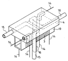
図2は、連結部4に入力されたエアー配管及び電気接続線の内部配置の様子を示す。図2は、連結部4と、コイルアセンブリ3と、コイルアセンブリ3のボビン19のみを図示する。
連結部4には複数のトンネルが設けられており、2個のトンネルには電気接続線14が通され、他の2個のトンネルはエアー配管15、16の一部を構成している。
コイルアセンブリ3への接続線(電気接続線14に含まれる。)は、コイルアセンブリの底面から床に向かって鉛直方向に引き出されて床に下り、床の上を延びてリニアモータの駆動回路の出力端子に接続されている。
【0033】
他の電気接続線(例えばフォーカスアクチュエータのコイルアセンブリへの接続線及び移動プレート(移動電極)10への接続線等)及びエアー配管15、16は、連結部4の底面から床に向かって鉛直方向に引き出されて床に下り、床の上を延びてフォーカスアクチュエータの駆動回路の出力端子、電源回路の出力端子、エアーコンプレッサ等に接続される。又、連結部4に入力された他の電気接続線及びエアー配管15、16は、連結部4の中を経由して連結部4から取り出され、それぞれの可動部に含まれるフォーカスアクチュエータのコイルアセンブリの端子、移動プレートの端子、フォーカスアクチュエータの静圧流体軸受の入力部及び静圧流体軸受18の入力部等に接続される。
エアー配管15、16は連結部4内の複数の箇所で屈折しており、エアー配管15、16が連結部4内を通過する距離が出来るだけ長くなるように構成されている。
【0034】
エアー配管15、16が連結部4内の複数の箇所で屈折することにより、流体の移動速度が抑えられ且つ流体の静圧が均一化される。又、連結部4内に多くの屈折箇所を設け、エアー配管の連結部内の通過距離が長くなるように構成することにより、駆動時にコイルアセンブリ3で発生して連結部4に伝えられた熱がエアー配管15、16を流れるエアーにより奪われ、連結部4が冷却される。
コイルアセンブリ3で発生した熱は移動ステージ1及び軸受18にほとんど伝達されず、移動ステージ1及び軸受18はほとんど温度上昇しない。従って、移動ステージ1又は軸受18が温度上昇により膨張し、送り精度又は位置精度が劣化するという問題は発生しない。
実施例の送り装置を使用する光ディスクの原盤記録装置は、高い精度で光ディスクの原盤に信号を記録する。
【0035】
他の実施例においては、エアー配管15、16は連結部4と独立の部材であり、連結部4と広い面積で接する。この構成によっても、駆動部で発生する熱が移動ステージ又は軸受18に伝わることを防止できる。
更に他の実施例においては、エアー配管15、16は駆動部を直接冷却する。(例えばコイルアセンブリ3とエアー配管15、16とが接している。)。
もっとも、一般的には、上記の実施例の構成のほうが、当該2つの他の実施例の構成よりも連結部4での冷却効果は大きい。
ガイド2は、静圧軸受、精密リニアガイドでもよい。
【0036】
【発明の効果】
本発明によれば、駆動部の発熱が軸受及び移動ステージに伝達しにくい構造を有し、移動ステージの精密な移動及び位置決めを行う送り装置を実現出来るという有利な効果が得られる。
本発明によれば、駆動部の発熱が軸受及び移動ステージに伝達しにくい構造を有し、移動ステージの精密な移動及び位置決めを行う小型でコストの安い送り装置を実現出来るという有利な効果が得られる。
【0037】
本発明によれば、流体配管及び電気接続線のねじり抵抗及び引きずり抵抗又はそれらの変化が小さく、移動ステージの精密な移動及び位置決めを行う送り装置を実現出来るという有利な効果が得られる。
【図面の簡単な説明】
【図1】本発明の実施例の送り装置の構成を示す図
【図2】本発明の実施例の送り装置の連結部の構成を示す図
【図3】粒子系の電気粘性流体の発現機構の原理を示す図
【図4】光ディスクの原盤記録装置の概略的な構成図
【図5】従来例の送り装置の概略的な構成を示す図
【符号の説明】
1 移動ステージ
2 ガイド
3 コイルアセンブリ(リニアモータの可動部)
4 連結部
5 ヨーク
6 永久磁石
7 センターヨーク
8 位置検出スケール
9 位置検出へッド
10 移動プレート(移動電極)
11 固定プレート(固定電極)
12 容器
13 電気粘性流体
14 電気接続線
15 スライダ部の静圧軸受用エアー配管
16 フオーカスアクチュエータ部の静圧軸受用エアー配管
17 粒子
18 静圧流体軸受
19 ボビン
101 レーザ発振器
102 エアースピンドル
103 スライダー
104 フォーカスアクチュエータ
105 ビームスポットモニタ
106 移動光学系
107 ガラス原盤
108 除振台[0001]
BACKGROUND OF THE INVENTION
The present invention relates to a precision feeding apparatus and an optical disk master recording apparatus including the precision feeding apparatus.
[0002]
[Prior art]
In recent years, with the increase in accuracy of optical discs and semiconductors, it has been strongly desired to increase the accuracy of these manufacturing apparatuses.
The present invention relates to a high-precision feeding device for a moving stage, and an arbitrary device including such a feeding device, for example, a master recording device for manufacturing a master of an optical disc having an allowable track pitch fluctuation of several nm or less, and a semiconductor It can be applied to other steppers.
[0003]
A high-accuracy moving stage feeder generally includes a hydrostatic bearing guide, a drive unit (for example, a linear motor or a piezoelectric element) that drives a movable unit along the guide, and a positioning mounted on the movable unit. It consists of a scale or a laser scale. Such a feeding device controls the position, speed, acceleration, and the like of the guide by feeding back scale reading information.
[0004]
FIG. 4 shows a schematic configuration of an optical disc master recording apparatus provided with a feeding device. 101 is a laser oscillator, 102 is an air spindle, 103 is a slider (included in a feeding device), 104 is a focus actuator, 105 is a beam spot monitor, 106 is a moving optical system, 107 is a glass master, and 108 is a vibration isolation table. is there.
The ultraviolet laser beam output from the
While the master disk is rotated by the
[0005]
The present invention is applicable to, for example, a master recording apparatus that manufactures a master of an optical disk shown in FIG.
FIG. 5 shows a schematic configuration diagram of a conventional moving stage feeding device (for a part of the fixed portion, refer to FIG. 1 showing the overall configuration diagram of the embodiment).
In FIG. 5, 1 is a moving stage, 2 is a guide (included in the fixed part), 3 is a coil assembly (movable part of the linear motor), 7 is a center yoke (included in the fixed part), and 14 is an electrical connection. 15 is an air pipe for a hydrostatic bearing of the slider portion, 18 is a hydrostatic bearing (hydrostatic pressure of fluid is applied in the direction of the arrow. In the conventional example and the embodiment, the fluid used is air (air 19) denotes a bobbin of the
The
[0006]
The coil assembly 3 and the bobbin 19 (both included in the movable part), the yoke and the permanent magnet (both included in the fixed part, not shown), etc. constitute a linear motor, and current is supplied to the coil assembly 3. The movable part is moved along the
The permanent magnets are disposed on both sides of the coil assembly 3, and the yoke magnetically connects the permanent magnets on both sides. The arrangement and configuration of the permanent magnet and yoke in the conventional example are similar to the arrangement and configuration of the permanent magnet 6 and yoke 5 in the embodiment of FIG.
The
The
[0007]
[Problems to be solved by the invention]
In the conventional example, the pipe and the electrical connection line are drawn from the side of the movable part as shown in FIG.
However, an ultra-precise moving stage having a vibration width during movement of the moving stage (in the embodiment, the vibration width in the direction parallel to the moving direction needs to be particularly small) of several nm or less (for example, 5 nm or less) will be realized. Then, the inventor of the present invention has found that the torsion resistance and drag resistance of the pipe and the electric connection line connecting the fixed part and the movable part become a problem.
An object of the present invention is to realize a feeding device that realizes precise movement and positioning of a moving stage and an optical disk master recording device including the feeding device that have low drag resistance of piping and electrical connection lines.
[0008]
Further, the feeding device of the conventional example has a structure in which heat generated by the drive unit (for example, the coil assembly 3) is easily transmitted to the bearing or the moving stage. For example, in FIG. 5, since the movable part of the linear motor including the coil assembly 3 and the member constituting the
Therefore, it has been difficult to realize an ultra-precise moving stage having a vibration width of several nm or less when moving the moving stage.
The present invention has a structure in which the heat generated by the drive unit is difficult to be transmitted to the bearing and the moving stage, and realizes a feeding device that realizes precise movement and positioning of the moving stage and an optical disc master recording device including the same. The purpose.
[0009]
[Means for Solving the Problems]
The invention described in
A moving stage,
A bearing for supporting a load between the movable part including the moving stage and the fixed part;
A drive unit for moving the movable unit;
A connection part that connects the moving stage and the bearing, and the drive part;
A pair of pipes that are provided in the connecting portion and refracted at a plurality of locations to supply a fluid;
The pair of pipes are arranged in a moving direction of the movable part, and are arranged point-symmetrically with respect to a horizontal plane center of the connecting part.
[0010]
In the conventional feeding device, the driving unit and the bearing or the moving stage are in direct contact with each other, and heat generated by the driving unit is easily transmitted to the bearing or the moving stage.
In the feeding device of the present invention, the drive unit, the bearing, and the moving stage are separated, and a connecting unit is provided therebetween. Furthermore, in the feeding device of the present invention, fluid piping is provided in the connecting portion, the driving portion, or both, and the connecting portion or the piping is cooled.
Due to the above structure, heat generated by the drive unit is not easily transmitted to the moving stage and the bearing. Even if the drive unit itself generates heat and expands thermally, the feed stage's feed accuracy and position accuracy depend on the stability of the move stage and the bearing, so the thermal expansion of the drive unit does not adversely affect the performance of the feed unit. .
The present invention has a structure in which the heat generated by the drive unit is difficult to be transmitted to the bearing and the moving stage, and has an effect of realizing a feeding device that performs precise movement and positioning of the moving stage.
[0011]
The “connecting portion” refers to an arbitrary member that connects the drive stage and a portion including the moving stage and the bearing.
A pipe having a portion that “contacts at least one of the connecting portion and the driving portion” belongs to the technical scope of the present invention.
For example, a pipe made by making a hole in the connecting portion (the side wall of the pipe also serves as the connecting portion) is included in the pipe “included in at least one of the pipes”.
The pipe embedded in the connecting portion is included in a pipe “included in at least one” or a pipe “contacting at least one”.
“Bearing” in “the connecting portion that connects the moving stage and the portion including the bearing and the driving portion” means the moving portion of the bearing because the moving stage is included in the moving portion.
“Fluid” includes gases and liquids.
[0012]
The invention according to
The bearing is a bearing using a fluid; and
The fluid supplied by the pipe is a fluid used for the bearing.
The feeding device according to
[0013]
The feeding device of the present invention cools the drive unit or the coupling unit using a pipe for supplying a fluid to the bearing. Since there is no need to add piping dedicated to cooling, the feeder can be reduced in size and cost.
The present invention has a structure in which heat generated by the drive unit is difficult to be transmitted to the bearing and the moving stage, and has a function of realizing a small-sized and low-cost feeding device that precisely moves and positions the moving stage.
Preferably, in order to enhance the cooling effect of the pipe and to slow down the flow rate of the fluid supplied to the hydrostatic bearing, the pipe is provided in (or in contact with) at least one place in the connecting part or the driving part. Has a refraction part.
[0020]
The invention according to claim 3 of the present invention is
The feeding device according to
A laser oscillator that outputs laser light;
A spindle that rotates the master,
A focus actuator for condensing modulated laser light and irradiating the master with the laser light;
A master optical disc recording apparatus characterized by having a.
[0021]
DETAILED DESCRIPTION OF THE INVENTION
DESCRIPTION OF THE PREFERRED EMBODIMENTS Embodiments that specifically show the best mode for carrying out the present invention will be described below with reference to the drawings.
FIG. 1 is a configuration diagram of a feeding device according to an embodiment of the present invention. 1A is a rear view, FIG. 1B is a plan view, and FIG. 1C is a front view (partially a sectional view). The feeding device of the embodiment is used as the
1 is a moving stage, 2 is a guide, 3 is a coil assembly (movable part of a linear motor), 4 is a connecting part, 5 is a yoke, 6 is a permanent magnet, 7 is a center yoke, 8 is a position detection scale, and 9 is a position detection. Head, 10 is a moving plate (moving electrode), 11 is a fixed plate (fixed electrode), 12 is a container, 13 is an electrorheological fluid, 14 is an electric connection line, 15 is an air piping for a hydrostatic bearing, 16 is a foreground An air pipe for a hydrostatic bearing of the slack actuator portion, 18 is a hydrostatic bearing, and 19 is a bobbin of a coil assembly.
[0022]
The
The
The coil assembly 3 wound around the
The two output terminals of the drive circuit of the linear motor provided in the fixed part and the two terminals of the coil assembly 3 are connected by two electric connection lines (included in the electric connection line 14). ).
[0023]
When a current is passed through the coil assembly 3 placed in the magnetic field generated by the permanent magnet 6 or the like, a driving force is generated in the coil assembly 3, and the movable part of the feeder is moved along the
In the feeding device of the embodiment used in the optical disk master recording device, the moving speed of the moving stage is 5 μm / sec to 10 μm / sec.
The position detection head 9 detects the amount of movement of the position detection scale 8. The linear motor is controlled based on the detected movement amount.
An
The moving plate (moving electrode) 10 moves in the
[0024]
A single electric connection line connects one terminal of a power supply circuit of high voltage (the voltage varies from 0.5 kV to 2.0 kV depending on the moving speed of the moving stage) and the moving plate (moving electrode) 10. (Included in the electrical connection line 14), the other one electrical connection line connects the other terminal of the high-voltage power supply circuit and the fixed plate (fixed electrode) 11. By applying a high voltage between the moving plate (moving electrode) 10 and the fixed plate (fixed electrode) 11, a high electric field corresponding to the applied voltage is generated between both plates. The
By applying a high electric field to the
[0025]
The
FIG. 3 shows how the
(A) When there is no electric field, the
(B) When a high electric field is applied to the electrorheological fluid, the
[0026]
In the embodiment, a voltage is applied between the
In order to reduce the resistance of the moving
Further, a magnetic fluid (fluid that generates high viscosity when a magnetic field is applied) may be used as the viscous fluid.
[0027]
A hydrostatic bearing 18 (in the embodiment, air is used as a fluid) is provided between the movable portion and the fixed portion. Air (air) is supplied to the hydrostatic fluid bearing 18 from an air compressor (not shown) provided in the fixed portion through the hydrostatic fluid bearing
The
In the optical disk master recording apparatus of the embodiment, focus servo is performed on the recording optical head portion mounted on the movable portion. The
[0028]
In the optical disk master recording apparatus of the embodiment, there is another portion between the movable portion and the fixed portion (the movable portion is driven by the focus actuator 104) of the recording optical head portion mounted on the moving stage. A hydrostatic bearing is provided.
Air (air) flows from an air compressor (not shown) provided in the fixed part to the other hydrostatic fluid bearing that supports the movable part driven by the focus actuator part through the
[0029]
The connecting
Further, the
The feeding device of the embodiment is mounted on a vibration isolation table 108 shown in FIG. 4 (not shown in FIG. 1), and
[0030]
The distance L2 from the bottom surface of the connecting
Therefore, the torsional resistance or dragging resistance of the air piping or the electric connection line hardly occurs (or does not change).
In the embodiment, the moving distance L1 of the moving
[0031]
Further, in the embodiment, an air pipe having a spiral shape is used. When the moving stage is moved, the spiral portion of the piping expands and contracts in the free portion from the bottom surface to the floor of the connecting
Therefore, the torsional resistance or dragging resistance of the air piping or the electric connection line hardly occurs (or does not change).
In the embodiment, a straight normal line is used as the electric connection line, but an electric connection line having a spiral shape may be used instead.
[0032]
FIG. 2 shows a state of the internal arrangement of the air pipe and the electric connection line input to the connecting
The connecting
A connection line (included in the electrical connection line 14) to the coil assembly 3 is drawn vertically from the bottom surface of the coil assembly toward the floor, descends to the floor, extends on the floor, and extends to the drive circuit of the linear motor. Connected to the output terminal.
[0033]
Other electric connection lines (for example, a connection line to the coil assembly of the focus actuator and a connection line to the moving plate (moving electrode) 10) and the
The
[0034]
Since the
The heat generated in the coil assembly 3 is hardly transmitted to the moving
An optical disk master recording apparatus using the feeding device of the embodiment records a signal on the optical disk master with high accuracy.
[0035]
In another embodiment, the
In yet another embodiment, the
However, in general, the configuration of the above-described embodiment has a larger cooling effect at the connecting
The
[0036]
【The invention's effect】
According to the present invention, there is an advantageous effect that it is possible to realize a feed device that has a structure in which the heat generated by the drive unit is difficult to be transmitted to the bearing and the moving stage, and that precisely moves and positions the moving stage.
According to the present invention, there is an advantageous effect that it is possible to realize a small-sized and low-cost feeding device that has a structure in which the heat generated by the drive unit is difficult to be transmitted to the bearing and the moving stage, and that precisely moves and positions the moving stage. It is done.
[0037]
According to the present invention, it is possible to obtain an advantageous effect that a torsional resistance and dragging resistance of a fluid pipe and an electric connection line or changes thereof are small, and a feed device that performs precise movement and positioning of a moving stage can be realized.
[Brief description of the drawings]
FIG. 1 is a diagram showing a configuration of a feeding device according to an embodiment of the present invention. FIG. 2 is a diagram showing a configuration of a connecting portion of the feeding device according to an embodiment of the present invention. FIG. 4 is a schematic configuration diagram of an optical disc master recording apparatus. FIG. 5 is a schematic configuration diagram of a conventional feeding apparatus.
1 Moving
4 connecting portion 5 yoke 6
11 Fixed plate (fixed electrode)
12
Claims (3)
前記移動ステージを含む可動部と固定部との間の荷重を支持する軸受と、
前記可動部を移動させる駆動部と、
前記移動ステージ及び軸受を含む部分と、前記駆動部とを連結する連結部と、
前記連結部に設けられると共に複数の箇所で屈折して流体を供給する一対の配管とを備え、
前記一対の配管は、前記可動部の移動方向に並び、かつ前記連結部の水平面中心に対して点対称に配置されている
ことを特徴とする送り装置。A moving stage,
A bearing for supporting a load between the movable part including the moving stage and the fixed part;
A drive unit for moving the movable unit;
A connection part that connects the moving stage and the bearing, and the drive part;
A pair of pipes that are provided in the connecting portion and refracted at a plurality of locations to supply a fluid;
The pair of pipes are arranged in a moving direction of the movable part and are arranged point-symmetrically with respect to a horizontal plane center of the connecting part.
前記配管により供給される流体が、前記軸受に使用される流体である、
ことを特徴とする請求項1に記載の送り装置。The bearing is a bearing using a fluid; and
The fluid supplied by the pipe is a fluid used for the bearing.
The feeding device according to claim 1.
レーザ光を出力するレーザ発振器と、
原盤を回転させるスピンドルと、
変調されたレーザ光を集光し前記原盤に前記レーザ光を照射するフォーカスアクチュエータと、
を有することを特徴とする光ディスク原盤記録装置。The feeding device according to claim 1 or 2,
A laser oscillator that outputs laser light;
A spindle that rotates the master,
A focus actuator for condensing modulated laser light and irradiating the master with the laser light;
An optical disc master recording apparatus comprising:
Priority Applications (1)
| Application Number | Priority Date | Filing Date | Title |
|---|---|---|---|
| JP2000323095A JP4405071B2 (en) | 2000-10-23 | 2000-10-23 | Feeding device and optical disc master recording device having the same |
Applications Claiming Priority (1)
| Application Number | Priority Date | Filing Date | Title |
|---|---|---|---|
| JP2000323095A JP4405071B2 (en) | 2000-10-23 | 2000-10-23 | Feeding device and optical disc master recording device having the same |
Publications (3)
| Publication Number | Publication Date |
|---|---|
| JP2002134390A JP2002134390A (en) | 2002-05-10 |
| JP2002134390A5 JP2002134390A5 (en) | 2006-06-01 |
| JP4405071B2 true JP4405071B2 (en) | 2010-01-27 |
Family
ID=18800849
Family Applications (1)
| Application Number | Title | Priority Date | Filing Date |
|---|---|---|---|
| JP2000323095A Expired - Fee Related JP4405071B2 (en) | 2000-10-23 | 2000-10-23 | Feeding device and optical disc master recording device having the same |
Country Status (1)
| Country | Link |
|---|---|
| JP (1) | JP4405071B2 (en) |
Families Citing this family (6)
| Publication number | Priority date | Publication date | Assignee | Title |
|---|---|---|---|---|
| KR101697896B1 (en) | 2003-04-11 | 2017-01-18 | 가부시키가이샤 니콘 | Apparatus and method for maintaining immersion fluid in the gap under the projection lens during wafer exchange in an immersion lithography machine |
| TWI540612B (en) | 2003-06-19 | 2016-07-01 | 尼康股份有限公司 | An exposure apparatus, an exposure method, and an element manufacturing method |
| US7589822B2 (en) | 2004-02-02 | 2009-09-15 | Nikon Corporation | Stage drive method and stage unit, exposure apparatus, and device manufacturing method |
| JP4655039B2 (en) * | 2004-06-07 | 2011-03-23 | 株式会社ニコン | Stage apparatus, exposure apparatus, and exposure method |
| USRE43576E1 (en) | 2005-04-08 | 2012-08-14 | Asml Netherlands B.V. | Dual stage lithographic apparatus and device manufacturing method |
| JP5097166B2 (en) | 2008-05-28 | 2012-12-12 | エーエスエムエル ネザーランズ ビー.ブイ. | Lithographic apparatus and method of operating the apparatus |
-
2000
- 2000-10-23 JP JP2000323095A patent/JP4405071B2/en not_active Expired - Fee Related
Also Published As
| Publication number | Publication date |
|---|---|
| JP2002134390A (en) | 2002-05-10 |
Similar Documents
| Publication | Publication Date | Title |
|---|---|---|
| WO2009147945A1 (en) | Information recording/reproducing device | |
| JP4405071B2 (en) | Feeding device and optical disc master recording device having the same | |
| JPS62208439A (en) | Photoelectric apparatus | |
| WO2009147943A1 (en) | Information recording/reproducing device | |
| JP3770367B2 (en) | Optical pickup device | |
| JP4594093B2 (en) | Drive device | |
| US6480364B1 (en) | Thermally compensated rotary positioning system for a disc drive | |
| KR100512101B1 (en) | Optical pick up actuator | |
| KR100587440B1 (en) | An object lens drive unit and an optical disk device | |
| KR100488005B1 (en) | Optical Pick-up actuator | |
| US9047883B2 (en) | Optical pickup device, optical information device, and information processing device | |
| CN100545920C (en) | Optical head actuator | |
| KR20060071251A (en) | Radiation structrus for lens holder of optical pick up actuator | |
| JP5263879B2 (en) | Pivot bearing and information recording / reproducing apparatus | |
| JP2948072B2 (en) | Magnetic recording / reproducing device | |
| JP2897090B2 (en) | Objective lens drive | |
| JP5207302B2 (en) | Information recording / reproducing head gimbal assembly and information recording / reproducing apparatus | |
| TWI260615B (en) | Optical pickup actuator and optical recording and reproducing apparatus and method for the same | |
| JP2001357574A (en) | Magneto-optical recording and reproducing device | |
| JPH11339291A (en) | Optical pickup device | |
| TW200404280A (en) | Optical pickup actuator, optical pickup employing the optical pickup actuator and optical disc drive apparatus employing the optical pickup | |
| JP3815728B2 (en) | Objective lens driving device and optical pickup device including the same | |
| JP2005141855A (en) | Objective lens drive unit and information recording/reproducing device | |
| JP2009146461A (en) | Objective lens driving apparatus | |
| JP2000215478A (en) | Object lens driving device |
Legal Events
| Date | Code | Title | Description |
|---|---|---|---|
| RD02 | Notification of acceptance of power of attorney |
Free format text: JAPANESE INTERMEDIATE CODE: A7422 Effective date: 20050523 |
|
| A521 | Written amendment |
Free format text: JAPANESE INTERMEDIATE CODE: A523 Effective date: 20060407 |
|
| A621 | Written request for application examination |
Free format text: JAPANESE INTERMEDIATE CODE: A621 Effective date: 20060407 |
|
| RD03 | Notification of appointment of power of attorney |
Free format text: JAPANESE INTERMEDIATE CODE: A7423 Effective date: 20061129 |
|
| A977 | Report on retrieval |
Free format text: JAPANESE INTERMEDIATE CODE: A971007 Effective date: 20080208 |
|
| A131 | Notification of reasons for refusal |
Free format text: JAPANESE INTERMEDIATE CODE: A131 Effective date: 20080507 |
|
| A521 | Written amendment |
Free format text: JAPANESE INTERMEDIATE CODE: A523 Effective date: 20080703 |
|
| A131 | Notification of reasons for refusal |
Free format text: JAPANESE INTERMEDIATE CODE: A131 Effective date: 20090106 |
|
| A521 | Written amendment |
Free format text: JAPANESE INTERMEDIATE CODE: A523 Effective date: 20090304 |
|
| TRDD | Decision of grant or rejection written | ||
| A01 | Written decision to grant a patent or to grant a registration (utility model) |
Free format text: JAPANESE INTERMEDIATE CODE: A01 Effective date: 20091006 |
|
| A01 | Written decision to grant a patent or to grant a registration (utility model) |
Free format text: JAPANESE INTERMEDIATE CODE: A01 |
|
| A61 | First payment of annual fees (during grant procedure) |
Free format text: JAPANESE INTERMEDIATE CODE: A61 Effective date: 20091104 |
|
| FPAY | Renewal fee payment (event date is renewal date of database) |
Free format text: PAYMENT UNTIL: 20121113 Year of fee payment: 3 |
|
| R150 | Certificate of patent or registration of utility model |
Free format text: JAPANESE INTERMEDIATE CODE: R150 |
|
| FPAY | Renewal fee payment (event date is renewal date of database) |
Free format text: PAYMENT UNTIL: 20121113 Year of fee payment: 3 |
|
| FPAY | Renewal fee payment (event date is renewal date of database) |
Free format text: PAYMENT UNTIL: 20131113 Year of fee payment: 4 |
|
| LAPS | Cancellation because of no payment of annual fees |