JP4404259B2 - Exhaust heat recovery boiler with auxiliary burner and its operation method - Google Patents
Exhaust heat recovery boiler with auxiliary burner and its operation method Download PDFInfo
- Publication number
- JP4404259B2 JP4404259B2 JP2004132806A JP2004132806A JP4404259B2 JP 4404259 B2 JP4404259 B2 JP 4404259B2 JP 2004132806 A JP2004132806 A JP 2004132806A JP 2004132806 A JP2004132806 A JP 2004132806A JP 4404259 B2 JP4404259 B2 JP 4404259B2
- Authority
- JP
- Japan
- Prior art keywords
- gas flow
- flow path
- exhaust gas
- temperature
- exhaust
- Prior art date
- Legal status (The legal status is an assumption and is not a legal conclusion. Google has not performed a legal analysis and makes no representation as to the accuracy of the status listed.)
- Expired - Fee Related
Links
Images


Description
本発明は、助燃バーナ付きの排熱回収ボイラに係り、特に助燃バーナに発熱量が低い燃料を用いるのに好適な助燃バーナ付き排熱回収ボイラとその運転方法に関する。 The present invention relates to an exhaust heat recovery boiler with an auxiliary burner, and more particularly to an exhaust heat recovery boiler with an auxiliary burner suitable for using a fuel with a low calorific value for the auxiliary burner and an operation method thereof.
ガスタービン(GT)からの燃焼排ガスの熱を回収して蒸気を発生させる排熱回収ボイラ(以下、HRSGということがある。)において、その入口ダクト部に助燃バーナを設け、その燃焼熱によりHRSGにおける蒸発量を増大させる形式が採られることがある。これは主に、夏場、気温が高くガスタービン出力が低下するときに、HRSGで発生した蒸気を用いる蒸気タービン(ST)の出力を増大させ、コンバインドサイクル発電全体としての出力を保持することを目的とする。 In an exhaust heat recovery boiler (hereinafter sometimes referred to as HRSG) that recovers heat of combustion exhaust gas from a gas turbine (GT) and generates steam, an auxiliary combustion burner is provided at the inlet duct portion, and the HRSG is generated by the combustion heat. In some cases, the form of increasing the amount of evaporation in is taken. This is mainly intended to increase the output of the steam turbine (ST) using steam generated by HRSG and maintain the output of the combined cycle power generation as a whole when the temperature is high and the gas turbine output decreases in summer. And
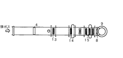
図7には従来技術の助燃バーナ付きの排熱回収ボイラの一部内部を示す側面図を示し、図8には図7の助燃バーナ付きの排熱回収ボイラの平面図を示す。
排ガスは、図示しないガスタービンより排ガスダクト2の入口ダクト3を通り、ボイラ本体7へ送られる。ボイラ本体7において伝熱管群13〜15から成る熱交換器(節炭器、蒸発器、再熱器、過熱器など)により排ガスの熱エネルギーを回収し、水から蒸気を発生させる。ボイラ本体7で熱回収された排ガスは、出口ダクト8を通り、煙突9より大気へ放出される。前記得られた蒸気は蒸気タービンに利用される。
FIG. 7 is a side view showing a part of a conventional exhaust heat recovery boiler with an auxiliary burner, and FIG. 8 is a plan view of the exhaust heat recovery boiler with an auxiliary burner of FIG.
Exhaust gas passes through the
図7に示すボイラ本体7には、入口ダクト3内に助燃バーナ4を設け、ボイラ本体7のガス最上流部に蒸発器13を設けている例を示している。ここで、ガスタービンを出た排ガスの温度は約600℃程度であるが、ボイラ本体7で要求される蒸発量に応じて助燃バーナ4へ燃料を供給し、その燃焼熱によってガスタービンからの排ガスを昇温する。なお、助燃バーナ4の点火時にはイグナイタを用いて着火させ、所定の温度に達した後は、燃料を供給し続けることで燃焼を保持する。
ガスタービンが一定の出力で運転され、排ガスの温度と流量が一定である場合には、助燃バーナ4からの入熱量は、要求される蒸発量(蒸気タービン出力要求)によって決まる。これに伴って助燃バーナ4へ供給する燃料の流量を加減するため、上記した従来技術では、要求される蒸発量と独立に助燃後の燃焼室R(助燃バーナ4の後流側の入口ダクト3内の空間)における排ガス温度を制御することはできない。
When the gas turbine is operated at a constant output and the temperature and flow rate of the exhaust gas are constant, the amount of heat input from the
ここで高炉ガス(BFG)等のカロリー(発熱量)の低い燃料を助燃用の燃料として燃焼させる場合、その点火時にはイグナイタを用いて気相燃焼させるが、連続運転時には燃焼室Rの温度を所定のガス温度以上に保持して燃焼性を良好に保つ必要がある。具体的には燃焼室Rのガス温度を約850℃以上に保持する必要がある。 Here, when fuel with low calories (calorific value) such as blast furnace gas (BFG) is burned as auxiliary combustion fuel, gas phase combustion is performed using an igniter at the time of ignition, but the temperature of the combustion chamber R is set to a predetermined value during continuous operation It is necessary to keep the gas temperature above the above to maintain good combustibility. Specifically, it is necessary to maintain the gas temperature in the combustion chamber R at about 850 ° C. or higher.
従って、上記従来技術では、蒸気タービンの出力要求が低下したとき等には、燃焼室Rの温度を所定のガス温度以上に保持できなくなり、高炉ガスの燃焼が不安定となったり、失火するという問題があった。 Therefore, in the above prior art, when the output demand of the steam turbine decreases, the temperature of the combustion chamber R cannot be maintained above a predetermined gas temperature, and the combustion of the blast furnace gas becomes unstable or misfires. There was a problem.
本発明の課題は、蒸気タービンの出力要求が低下したときでも燃焼室の温度を所定のガス温度以上に保持して高炉ガスの燃焼が不安定にならないようにした助燃バーナ付き排熱回収ボイラとその運転方法を提供することである。 An object of the present invention is to provide an exhaust heat recovery boiler with an auxiliary combustion burner that maintains the temperature of the combustion chamber at a predetermined gas temperature or higher so that the combustion of the blast furnace gas does not become unstable even when the output demand of the steam turbine decreases. It is to provide a driving method.
請求項1記載の発明は、ガスタービンからの燃焼排ガスの熱を回収して蒸気を発生させる複数の熱交換器(伝熱管群)を排ガス流路内に配置し、前記熱交換器(伝熱管群)を配置した排ガス流路(2)の前流側の入口ダクト部に高炉ガスを燃料として用いる助燃バーナ(4)を配置した助燃バーナ付き排熱回収ボイラにおいて、前記排ガス流路(2)を迂回して、前記助燃バーナ(4)の前流側の排ガス流路(2)から分岐し、前記複数の熱交換器(伝熱管群)の中の最上流側の熱交換器(13)の後流側の排ガス流路(2)に接続したバイパス流路(10)を設け、前記排ガス流路内の助燃バーナ配置部位の前流側と前記バイパス流路内の少なくともいずれか又は前記排ガス流路(2)とバイパス流路(10)との分岐部にガス流量配分調整手段(11a及び11b)を設け、前記排ガス流路内の助燃バーナ配置部位の後流側であって、前記複数の熱交換器(伝熱管群)の中の最上流側の熱交換器(13)の前流側(燃焼室)に温度計測手段(6a)を設け、更に、前記温度計測手段(6a)で計測される温度が一定値以上である場合は、該温度計測手段(6a)が設けられた排ガス流路(2)のガス流量を前記温度が一定値以上である時点のガス流量から増大させると共に、バイパス流路(10)のガス流量を前記温度が一定値以上である時点のガス流量から低減させるように前記ガス流量配分調整手段(11a及び11b)を調整し、前記温度計測手段(6a)で計測される温度が一定値未満である場合は、温度計測手段(6a)が設けられた排ガス流路(2)のガス流量を前記温度が一定値未満である時点のガス流量から低減させると共に、バイパス流路(10)のガス流量を前記温度が一定値未満である時点のガス流量から増大させるように前記ガス流量配分調整手段(11a及び11b)を調整する制御を行う制御装置を設けた助燃バーナ付き排熱回収ボイラである。 According to the first aspect of the present invention, a plurality of heat exchangers (heat transfer tube groups) that generate steam by collecting heat of the combustion exhaust gas from the gas turbine are arranged in the exhaust gas flow path, and the heat exchanger (heat transfer tube) In the exhaust heat recovery boiler with an auxiliary combustion burner in which an auxiliary combustion burner (4) using blast furnace gas as fuel is arranged in the inlet duct portion on the upstream side of the exhaust gas passage (2) in which the group) is disposed, the exhaust gas passage (2) , Branching from the exhaust gas flow path (2) on the upstream side of the auxiliary burner (4), and the heat exchanger (13) on the most upstream side in the plurality of heat exchangers (heat transfer tube group) A bypass passage (10) connected to the exhaust gas passage (2) on the downstream side is provided, and at least one of the upstream side of the auxiliary burner arrangement site in the exhaust gas passage and the bypass passage, or the exhaust gas Gas flow distribution adjustment at the branch of the flow path (2) and bypass flow path (10) Means (11a and 11b) are provided, and the heat exchanger (13 on the most upstream side in the plurality of heat exchangers (heat transfer tube group) on the downstream side of the auxiliary combustion burner arrangement portion in the exhaust gas passage. ) Is provided with a temperature measuring means (6a) on the upstream side (combustion chamber), and when the temperature measured by the temperature measuring means (6a) is a predetermined value or more, the temperature measuring means (6a) The gas flow rate in the provided exhaust gas flow path (2) is increased from the gas flow rate at the time when the temperature is above a certain value, and the gas flow rate in the bypass flow path (10) is increased at a time when the temperature is above a certain value. When the gas flow distribution adjusting means (11a and 11b) is adjusted to reduce the gas flow rate and the temperature measured by the temperature measuring means (6a) is less than a certain value, the temperature measuring means (6a) The gas flow rate in the provided exhaust gas flow path (2) The gas flow rate distribution adjusting means reduces the gas flow rate when the temperature is less than a certain value and increases the gas flow rate of the bypass passage (10) from the gas flow rate when the temperature is less than the certain value. It is a waste heat recovery boiler with an auxiliary burner provided with a control device that performs control to adjust (11a and 11b).
請求項2記載の発明は、前記バイパス流路(10)からの分岐排ガスを前記排ガス流路(2)に導入する接続部に前記両方の流路のガスを混合する1以上のミキシング部材(17)を設けた請求項1記載の助燃バーナ付き排熱回収ボイラである。
The invention according to
請求項3記載の発明は、各ミキシング部材(17)とバイパス流路(10)との連絡部にガス流量配分調整手段を設け、前記ミキシング部材(17)の後流側の排ガス流路内に温度計測手段(6b)を設けた請求項2記載の助燃バーナ付き排熱回収ボイラである。
According to a third aspect of the invention, each mixing member (17) and the bypass flow path connecting portion between the (10) provided with a gas flow distribution adjusting hand stage, the mixing member (17) of the downstream side of the exhaust gas flow path The exhaust heat recovery boiler with an auxiliary combustion burner according to
請求項4記載の発明は、ガスタービンからの燃焼排ガスの熱を回収して蒸気を発生させる複数の熱交換器(伝熱管群)を排ガス流路内に配置し、前記熱交換器(伝熱管群)を配置した排ガス流路(2)の前流側の入口ダクト部に高炉ガスを燃料として用いる助燃バーナ(4)を配置し、前記排ガス流路(2)を迂回して、前記助燃バーナ(4)の前流側の排ガス流路(2)から分岐し、前記複数の熱交換器(伝熱管群)の中の最上流側の熱交換器(13)の後流側の排ガス流路(2)に接続したバイパス流路(10)を設け、前記排ガス流路内の助燃バーナ配置部位の前流側と前記バイパス流路内の少なくともいずれか又は前記排ガス流路(2)とバイパス流路(10)との分岐部にガス流量配分調整手段(11a及び11b)を設け、前記排ガス流路内の助燃バーナ配置部位の後流側であって、前記複数の熱交換器(伝熱管群)の中の最上流側の熱交換器(13)の前流側に温度計測手段(6a)を設けた助燃バーナ付き排熱回収ボイラの運転方法であって、前記温度計測手段(6a)で計測される温度が一定値以上である場合は、該温度計測手段(6a)が設けられた排ガス流路(2)のガス流量を前記温度が一定値以上である時点のガス流量から増大させると共に、バイパス流路のガス流量を前記温度が一定値以上である時点のガス流量から低減させるように前記ガス流量配分調整手段(11a及び11b)を調整し、前記温度計測手段(6a)で計測される温度が一定値未満である場合は、温度計測手段(6a)が設けられた排ガス流路(2)のガス流量を前記温度が一定値未満である時点のガス流量から低減させると共に、バイパス流路のガス流量を前記温度が一定値未満である時点のガス流量から増大させるように前記ガス流量配分調整手段(11a及び11b)を調整する助燃バーナ付き排熱回収ボイラの運転方法である。 According to a fourth aspect of the present invention, a plurality of heat exchangers (heat transfer tube groups) for recovering heat of the combustion exhaust gas from the gas turbine and generating steam are disposed in the exhaust gas flow path, and the heat exchanger (heat transfer tube) The auxiliary combustion burner (4) using blast furnace gas as a fuel is disposed in the inlet duct portion on the upstream side of the exhaust gas flow path (2) where the group) is disposed, bypassing the exhaust gas flow path (2), and the auxiliary combustion burner The exhaust gas flow path on the upstream side of the heat exchanger (13) on the most upstream side of the plurality of heat exchangers (heat transfer tube group) is branched from the exhaust gas flow path (2) on the upstream side of (4). A bypass flow path (10) connected to (2) is provided, and at least one of the upstream flow side of the auxiliary burner arrangement site in the exhaust gas flow path and the bypass flow path, or the exhaust gas flow path (2) and the bypass flow Gas flow distribution adjusting means (11a and 11b) is provided at a branch portion with the passage (10), Temperature measuring means (on the downstream side of the auxiliary burner arrangement site in the gas flow path, on the upstream side of the most upstream heat exchanger (13) in the plurality of heat exchangers (heat transfer tube group)) 6a), the temperature measuring means (6a) is provided when the temperature measured by the temperature measuring means (6a) is equal to or higher than a certain value. The gas flow rate in the exhaust gas flow path (2) is increased from the gas flow rate at the time when the temperature is above a certain value, and the gas flow rate in the bypass flow path is reduced from the gas flow rate at the time when the temperature is above a certain value. When the gas flow distribution adjusting means (11a and 11b) is adjusted as described above and the temperature measured by the temperature measuring means (6a) is less than a certain value, the exhaust gas flow provided with the temperature measuring means (6a) The temperature is constant at the gas flow rate in the passage (2) The gas flow distribution adjusting means (11a and 11b) is adjusted so as to reduce the gas flow rate at the time when the temperature is less than the gas flow rate and increase the gas flow rate of the bypass passage from the gas flow rate at the time when the temperature is less than a certain value. This is a method for operating a waste heat recovery boiler with an auxiliary burner.
請求項5記載の発明は、更に、前記バイパス流路(10)からの分岐排ガスを前記排ガス流路(2)に導入する接続部に前記両方の流路のガスを混合する1以上のミキシング部材(17)を設け、各ミキシング部材(17)とバイパス流路との連絡部にガス流量配分調整手段を設け、前記ミキシング部材(17)の後流側の排ガス流路内に温度計測手段を設けた助燃バーナ付き排熱回収ボイラの運転方法であって、ミキシング部材(17)の後流側の排ガス流路内に設けた温度計測手段(6b)で計測される温度が一定値以上となるように前記各ミキシング部材(17)とバイパス流路(10)との連絡部に設けられたガス流量配分調整手段を用いて各ミキシング部材(17)から排ガス流路側に流れるガス流量を調整することを特徴とする請求項4記載の助燃バーナ付き排熱回収ボイラの運転方法である。
The invention according to
請求項1及び4記載の発明によれば、要求蒸発量が少ない場合、すなわち助燃量が少なくて良い場合には、ガスタービンからの排ガスをガス流量配分調整手段により一部をバイパス流路側に流し、排ガス流路(本流側である助燃バーナが設けられた入口ダクト)側を流れるガス流量をガス流量配分調整手段により低減させ、助燃バーナによる燃焼負荷を下げても助燃後の排ガス温度を所定温度以上に維持できる。また、助燃後の排ガス温度が設定温度以上に上昇した場合は、排ガス流路側を流れるガス流量を増大させ、バイパス流路側のガス流量を低減させることにより、助燃後の排ガス温度を設定温度以下とすることができる。
こうして発熱量の低い高炉ガス(BFG)でも助燃用の燃料として有効利用でき、製鉄所でコンバインドサイクルプラントとして本発明の助燃バーナ付き排熱回収ボイラを使用できる。また、助燃後の排ガス温度を所定温度以上に維持できる。
According to the first and fourth aspects of the present invention, when the required evaporation amount is small, that is, when the auxiliary combustion amount is small, a part of the exhaust gas from the gas turbine is caused to flow to the bypass flow path side by the gas flow distribution adjusting means. The flow rate of the gas flowing through the exhaust gas flow path (inlet duct provided with the auxiliary burner on the main stream side) is reduced by the gas flow distribution adjusting means, and the exhaust gas temperature after the auxiliary combustion is maintained at a predetermined temperature even if the combustion load by the auxiliary burner is reduced. This can be maintained. In addition, if the exhaust gas temperature after the auxiliary combustion rises above the set temperature, the exhaust gas temperature after the auxiliary combustion is reduced to the set temperature or lower by increasing the gas flow rate flowing through the exhaust gas flow channel side and reducing the gas flow rate on the bypass flow channel side. can do.
Thus, even blast furnace gas (BFG) having a low calorific value can be effectively used as a fuel for auxiliary combustion, and the exhaust heat recovery boiler with an auxiliary combustion burner of the present invention can be used as a combined cycle plant at an ironworks. Moreover, the exhaust gas temperature after auxiliary combustion can be maintained at a predetermined temperature or higher.
請求項2記載の発明によれば、バイパス流路を流れるガスと排ガス流路を流れるガスの合流部にはミキシング部材を設けて両方から流れてくるガスを混合して温度差を無くし、後流の管群の伝熱量を精度良く設定できるようにする。 According to the second aspect of the present invention, a mixing member is provided at the joining portion of the gas flowing in the bypass flow path and the gas flowing in the exhaust gas flow path to mix the gas flowing from both to eliminate the temperature difference, and The heat transfer amount of the tube group can be set accurately.
請求項3、5記載の発明によれば、ミキシング部材の後流側の排ガス流路内に設けた温度計測手段の測定温度に基づき、各ミキシング部材とバイパス流路との連絡部の中のガス流量配分調整手段をそれぞれ独自に作動することでガス配分を調整して、その下流側に流れるガスに温度分布が生じないようにすることができる。 According to the third and fifth aspects of the invention, the gas in the connecting portion between each mixing member and the bypass flow path is based on the measured temperature of the temperature measuring means provided in the exhaust gas flow path on the downstream side of the mixing member. The gas distribution can be adjusted by independently operating the flow distribution adjusting means so that the temperature distribution does not occur in the gas flowing downstream thereof.
本発明の実施例について図面と共に説明する。 Embodiments of the present invention will be described with reference to the drawings.
図1、図2、図3はそれぞれ、本実施例の排熱回収ボイラの一部内部構造を示す側面図と平面図と斜視図である。図1において排ガスは、排ガスダクト2と入口ダクト3を通り、ボイラ本体7へ送られる。ボイラ本体7において、排ガスの熱エネルギーを蒸発器などの伝熱管群13、14、15内を流れる水を加熱させて蒸気を発生させる。ボイラ本体7で熱回収された排ガスは出口ダクト8を通り、煙突9から大気へ放出される。入口ダクト3の内部にはボイラ本体7の蒸発量を増量させる目的で助燃バーナ4が設けられている。
1, 2, and 3 are a side view, a plan view, and a perspective view, respectively, showing a partial internal structure of the exhaust heat recovery boiler of this embodiment. In FIG. 1, the exhaust gas passes through the
また、排ガスダクト2から入口ダクト3へ流れる排ガス本流の他に排ガスダクト2から分岐し、ボイラ本体7へ排ガスの一部を流すためのバイパスダクト10を設ける。バイパスダクト10の入口側、すなわち排ガスダクト2との接続部側にはバイパスダクト側ダンパ11aを設け、また入口ダクト3内の助燃バーナ4の前流側には助燃バーナ側ダンパ11bを設ける。さらにバイパスダクト10とボイラ本体7との接続部側にはミキシング部材17を設けている。さらにミキシング部材17の前側のボイラ本体7の内部に配置された伝熱管群13の前流部には、排ガス温度計6aが設けられている。
Further, in addition to the exhaust gas main stream flowing from the
高炉ガスは発熱量が小さく、助燃用の燃料として適していなかったので従来は単純に燃焼させて廃棄されていた。その高炉ガスを助燃燃料として使用する場合は、その燃焼性があまり良くないので入口ダクト3内の燃焼室Rのガス温度を約850℃以上に保持する必要がある。助燃量は蒸気タービンでの要求蒸発量で決まるが、要求蒸発量が少ない場合、すなわち助燃量が少ない場合にはボイラ本体7内を流れる本流のガス全量と高炉ガスとを混合すると燃焼室Rの温度は850℃まで上がらない。
Since blast furnace gas has a small calorific value and was not suitable as a fuel for supplementary combustion, it has conventionally been simply burned and discarded. When the blast furnace gas is used as a supplementary fuel, the gas temperature in the combustion chamber R in the
そこで、燃焼室Rに設けた排ガス温度計6aの計測値を読み取り、850℃を保持できるように、助燃バーナ側ダンパ11bを絞り、バイパスダクト側ダンパ11aを開いて、前記本流側のガス流量を低減させ、バイパス側のガス流量を増大させるように調節する。
Therefore, the measured value of the exhaust gas thermometer 6a provided in the combustion chamber R is read, and the auxiliary
一方、排ガス温度計6aの計測値の温度が設定温度以上に上昇した場合は、助燃バーナ側ダンパ11bを開き、バイパスダクト側ダンパ11aを絞って、ボイラ本体7を流れる本流側のガス流量を増大させ、バイパスダクト10側のガス流量を低減させるか、または、参考例として、助燃量を低減させることにより、設定温度以下となるようにする。
On the other hand, when the temperature of the measured value of the exhaust gas thermometer 6a rises above the set temperature, the auxiliary combustion
助燃バーナ4で得られた熱ガスとタービン排ガスとの混合したガス5は伝熱管群13を通過する際に熱吸収され、温度が低下する。排ガスの中でバイパスダクト10に分岐されたガス12と伝熱管群13を通過する際に熱吸収され、温度が低下したガス16は通常では温度が相違するので、単純に混合すると管群13の入口ガスは大きな温度分布を生じることになる。すなわち、ボイラ本体7のガス流れ方向の横断断面形状は、例えば高さが20m以上で幅が6m以上と大きいので、ケーシングの一部に、そのままバイパスダクト10を接続したり、入口ダクト3からのガス16とバイパスダクト10内のガス12の流れを仕切るような構成としたのでは、合流前の前記二つのガス温度差により伝熱管群14、15の伝熱量を精度よく設定できない。そこでボイラ本体7とバイパスダクト10の接続部にミキシング部材17を設け、二つのガス12,16が混合したガスが管群14の入口で均一なガス温度になるようにする。これにより、二つのガス12、16の混合領域での温度差を小さくできる。
The
伝熱管群13としては、燃焼室Rのガス温度が高温となるので、熱吸収量が大きい蒸発器であることが望ましい。これにより当該材質は、他の熱交換器(過熱器、再熱器)とする場合に比べて耐熱性の低いものとすることができる。
The heat
ここで、助燃バーナ4は、例えば、入口ダクト3のガス流れの横断面の幅方向に複数の燃料供給口を有する配管が上下方向に数段配置された構成からなる。助燃バーナ4からの火炎が直接伝熱管群13に局部的に到達することが無いように、また、伝熱管群13が輻射熱を均等に受けることができるように、上流から下流へ拡大する形状の入口ダクト3の上流側に助燃バーナ4を設けることが望ましい。助燃バーナ4から下流側に向けて入口ダクト3の断面積が拡大してガス流速が低下する伝熱管群13までの間には、燃焼室Rとして十分な空間が設けられている。
Here, the
ミキシング部材17は翼形状で内部が空洞になっており、その中をバイパスダクト10から流入したガス12が流通する。またボイラ本体7内ではミキシング部材17の表面にある開口部からボイラ本体7内へガス12を導入するようになっている。なお、ミキシング部材17の翼形状は一例であり、この形状に限定されるものではない。
The mixing
ミキシング部材17のボイラ本体7の内部における配置、数、間隔およびその開口部の形状、数、間隔等はプラント毎に最適のものが選択される。ミキシング部材17は、その長手方向が水平方向に向けて配置されるが、その他にバイパスダクト10が入口ダクト3の上方に設けられるような場合、その長手方向を垂直方向に向けて配置しても良い。
The arrangement, number, and spacing of the mixing
ミキシング部材17の後流側のボイラ本体7内にある伝熱管群14の前流部には、複数の排ガス温度計6bを設けてもよい。この場合、バイパスダクト10側のダンパ11aに代えて、バイパスダクト10とミキシング部材17の連絡部に、ミキシング部材17毎にガス流量調節手段を設け(図示せず:例えばスライド式)、複数の排ガス温度計6bで測定される温度が適切な条件となるようにガス流量を個別に調節しても良い。これにより、例えば伝熱管群14を通過するガス温度に分布が生じないようにすることができる。
A plurality of
図4、図5、図6には、本発明からなるバイパスダクト10を設けた助燃バーナ付き排熱回収ボイラの一部内部構造を示す側面図、平面図及び斜視図を示す。本実施例の構成で実施例1のそれと同様のものは同一符号を付し、その説明を省略する。障害物等でバイパスダクトの配置が難しい場合には図4のようなバイパスダクトの配置となる。
4, 5, and 6 are a side view, a plan view, and a perspective view showing a partial internal structure of an exhaust heat recovery boiler with a combustion burner provided with a
排ガスダクト2から分岐し、ボイラ本体7へ繋ぐバイパスダクト10内にダンパ11aを設けている。助燃バーナ4の燃焼時には、ダンパ11aの開閉により排ガスのバイパスダクト10側への流量を調整することで、助燃バーナ4側に流れる排ガス流量を制御する。こうして、助燃後の排ガス5の温度を一定に制御できる。
A
また、助燃バーナ4を燃焼させていないとき(未使用時)には、ダンパ11aは閉となっている。
Further, when the
なお、ダンパ11aの代わりにダクトの分岐部に分配弁状のもの(図示せず)を設け、バイパス側と本流側のガス流量を調整するものでも良い。
In addition, instead of the
本発明ではバイパスダクト10の配置形状等は上記のものに限定されない。
In the present invention, the arrangement shape of the
本発明は、製鉄所に設置するコンバインドサイクルプラントで、高炉ガス等のカロリー(発熱量)の低い燃料の燃焼性を良好に保って燃焼させる助燃バーナ付き排熱回収ボイラに利用できる。 INDUSTRIAL APPLICABILITY The present invention is a combined cycle plant installed in an ironworks, and can be used for an exhaust heat recovery boiler with an auxiliary burner that burns while maintaining good combustibility of fuel with low calories (calorific value) such as blast furnace gas.
2 排ガスダクト 3 入口ダクト
4 助燃バーナ 6a、6b 排ガス温度計
7 ボイラ本体 8 出口ダクト
9 煙突 10 バイパスダクト
11a バイパスダクト側ダンパ
11b 助燃バーナ側ダンパ
13、14、15 伝熱管群
17 ミキシング部材
5、12、16 ガス
R 燃焼室
2
Claims (5)
前記排ガス流路を迂回して、前記助燃バーナの前流側の排ガス流路から分岐し、前記複数の熱交換器の中の最上流側の熱交換器の後流側の排ガス流路に接続したバイパス流路を設け、
前記排ガス流路内の助燃バーナ配置部位の前流側と前記バイパス流路内の少なくともいずれか又は前記排ガス流路とバイパス流路との分岐部にガス流量配分調整手段を設け、
前記排ガス流路内の助燃バーナ配置部位の後流側であって、前記複数の熱交換器の中の最上流側の熱交換器の前流側に温度計測手段を設け、
更に、前記温度計測手段で計測される温度が一定値以上である場合は、該温度計測手段が設けられた排ガス流路のガス流量を前記温度が一定値以上である時点のガス流量から増大させると共に、バイパス流路のガス流量を前記温度が一定値以上である時点のガス流量から低減させるように前記ガス流量配分調整手段を調整し、前記温度計測手段で計測される温度が一定値未満である場合は、温度計測手段が設けられた排ガス流路のガス流量を前記温度が一定値未満である時点のガス流量から低減させると共に、バイパス流路のガス流量を前記温度が一定値未満である時点のガス流量から増大させるように前記ガス流量配分調整手段を調整する制御を行う制御装置を設けたことを特徴とする助燃バーナ付き排熱回収ボイラ。 A plurality of heat exchangers for recovering the heat of the combustion exhaust gas from the gas turbine and generating steam are disposed in the exhaust gas flow path, and a blast furnace is provided at the inlet duct portion on the upstream side of the exhaust gas flow path where the heat exchanger is disposed. In an exhaust heat recovery boiler with an auxiliary burner in which an auxiliary burner that uses gas as fuel is arranged,
Bypassing the exhaust gas flow path, branching from the exhaust gas flow path on the upstream side of the auxiliary burner, and connecting to the exhaust gas flow path on the downstream side of the heat exchanger on the most upstream side of the plurality of heat exchangers Provided bypass flow path,
Gas flow distribution adjusting means is provided at a branch portion between the exhaust gas flow path and the bypass flow path or at least one of the auxiliary flow burner arrangement site in the exhaust gas flow path and at least one of the bypass flow path,
A temperature measuring means is provided on the upstream side of the heat exchanger on the most upstream side of the plurality of heat exchangers on the downstream side of the auxiliary combustion burner arrangement site in the exhaust gas flow path,
Further, when the temperature measured by the temperature measuring means is equal to or higher than a certain value, the gas flow rate of the exhaust gas passage provided with the temperature measuring means is increased from the gas flow rate at the time when the temperature is equal to or higher than the certain value. In addition, the gas flow distribution adjusting means is adjusted so as to reduce the gas flow rate in the bypass flow path from the gas flow rate at the time when the temperature is equal to or higher than a certain value, and the temperature measured by the temperature measuring means is less than a certain value. In some cases, the gas flow rate in the exhaust gas flow channel provided with temperature measuring means is reduced from the gas flow rate at the time when the temperature is less than a certain value, and the gas flow rate in the bypass flow channel is less than the certain value. An exhaust heat recovery boiler with an auxiliary burner, characterized in that a control device is provided for performing control to adjust the gas flow rate distribution adjusting means so as to increase from the gas flow rate at the time.
前記排ガス流路を迂回して、前記助燃バーナの前流側の排ガス流路から分岐し、前記複数の熱交換器の中の最上流側の熱交換器の後流側の排ガス流路に接続したバイパス流路を設け、
前記排ガス流路内の助燃バーナ配置部位の前流側と前記バイパス流路内の少なくともいずれか又は前記排ガス流路とバイパス流路との分岐部にガス流量配分調整手段を設け、
前記排ガス流路内の助燃バーナ配置部位の後流側であって、前記複数の熱交換器の中の最上流側の熱交換器の前流側に温度計測手段を設けた助燃バーナ付き排熱回収ボイラの運転方法であって、
前記温度計測手段で計測される温度が一定値以上である場合は、該温度計測手段が設けられた排ガス流路のガス流量を前記温度が一定値以上である時点のガス流量から増大させると共に、バイパス流路のガス流量を前記温度が一定値以上である時点のガス流量から低減させるように前記ガス流量配分調整手段を調整し、前記温度計測手段で計測される温度が一定値未満である場合は、温度計測手段が設けられた排ガス流路のガス流量を前記温度が一定値未満である時点のガス流量から低減させると共に、バイパス流路のガス流量を前記温度が一定値未満である時点のガス流量から増大させるように前記ガス流量配分調整手段を調整することを特徴とする助燃バーナ付き排熱回収ボイラの運転方法。 A plurality of heat exchangers for recovering the heat of the combustion exhaust gas from the gas turbine and generating steam are disposed in the exhaust gas flow path, and a blast furnace is provided at the inlet duct portion on the upstream side of the exhaust gas flow path where the heat exchanger is disposed. An auxiliary burner that uses gas as fuel is placed,
Bypassing the exhaust gas flow path, branching from the exhaust gas flow path on the upstream side of the auxiliary burner, and connecting to the exhaust gas flow path on the downstream side of the heat exchanger on the most upstream side of the plurality of heat exchangers Provided bypass flow path,
Gas flow distribution adjusting means is provided at a branch portion between the exhaust gas flow path and the bypass flow path or at least one of the auxiliary flow burner arrangement site in the exhaust gas flow path and at least one of the bypass flow path,
Exhaust heat with an auxiliary burner provided with a temperature measuring means on the upstream side of the heat exchanger on the uppermost stream side of the plurality of heat exchangers, on the downstream side of the auxiliary burner arrangement site in the exhaust gas flow path A method for operating a recovery boiler,
When the temperature measured by the temperature measuring means is a certain value or more, the gas flow rate of the exhaust gas flow path provided with the temperature measuring means is increased from the gas flow rate at the time when the temperature is more than a certain value, When the gas flow distribution adjusting means is adjusted to reduce the gas flow rate of the bypass flow path from the gas flow rate at the time when the temperature is equal to or higher than a certain value, and the temperature measured by the temperature measuring device is less than a certain value Reduces the gas flow rate of the exhaust gas flow path provided with the temperature measuring means from the gas flow rate at the time when the temperature is less than a certain value, and reduces the gas flow rate of the bypass flow path at the time when the temperature is less than the certain value. A method of operating an exhaust heat recovery boiler with an auxiliary burner, characterized in that the gas flow distribution adjusting means is adjusted so as to increase from the gas flow rate.
ミキシング部材の後流側の排ガス流路内に設けた温度計測手段で計測される温度が一定値以上となるように前記各ミキシング部材とバイパス流路との連絡部に設けられたガス流量配分調整手段を用いて各ミキシング部材から排ガス流路側に流れるガス流量を調整することを特徴とする請求項4記載の助燃バーナ付き排熱回収ボイラの運転方法。 Further, at least one mixing member that mixes the gas in both of the flow paths is provided at a connection portion that introduces the branched exhaust gas from the bypass flow path into the exhaust gas flow path, and a connection portion between each mixing member and the bypass flow path Provided with a gas flow distribution adjusting means, and an operating method of the exhaust heat recovery boiler with a combustion burner provided with a temperature measuring means in the exhaust gas flow path on the downstream side of the mixing member,
Gas flow distribution adjustment provided at the connecting portion between each mixing member and the bypass flow path so that the temperature measured by the temperature measuring means provided in the exhaust gas flow path on the downstream side of the mixing member becomes a certain value or more. 4. auxiliary burner with heat recovery steam generator operating method of the wherein that you adjust the gas flow through the exhaust gas flow path from the mixing member using means.
Priority Applications (1)
| Application Number | Priority Date | Filing Date | Title |
|---|---|---|---|
| JP2004132806A JP4404259B2 (en) | 2004-04-28 | 2004-04-28 | Exhaust heat recovery boiler with auxiliary burner and its operation method |
Applications Claiming Priority (1)
| Application Number | Priority Date | Filing Date | Title |
|---|---|---|---|
| JP2004132806A JP4404259B2 (en) | 2004-04-28 | 2004-04-28 | Exhaust heat recovery boiler with auxiliary burner and its operation method |
Publications (3)
| Publication Number | Publication Date |
|---|---|
| JP2005315492A JP2005315492A (en) | 2005-11-10 |
| JP2005315492A5 JP2005315492A5 (en) | 2007-06-07 |
| JP4404259B2 true JP4404259B2 (en) | 2010-01-27 |
Family
ID=35443103
Family Applications (1)
| Application Number | Title | Priority Date | Filing Date |
|---|---|---|---|
| JP2004132806A Expired - Fee Related JP4404259B2 (en) | 2004-04-28 | 2004-04-28 | Exhaust heat recovery boiler with auxiliary burner and its operation method |
Country Status (1)
| Country | Link |
|---|---|
| JP (1) | JP4404259B2 (en) |
Families Citing this family (5)
| Publication number | Priority date | Publication date | Assignee | Title |
|---|---|---|---|---|
| EP2930423B1 (en) * | 2012-12-06 | 2017-02-08 | Panasonic Intellectual Property Management Co., Ltd. | Combined heat and power system |
| JP6183759B2 (en) * | 2013-04-22 | 2017-08-23 | パナソニックIpマネジメント株式会社 | Combined heat and power system |
| CN104197301B (en) * | 2014-08-29 | 2016-05-11 | 安徽海螺川崎节能设备制造有限公司 | Cement kiln exhaust heat recovery power generation bypass boiler |
| CN104654385B (en) * | 2015-01-28 | 2017-02-01 | 广东合一新材料研究院有限公司 | Waste heat recycling device |
| CN109254108B (en) * | 2017-07-12 | 2023-02-17 | 株式会社堀场制作所 | Analysis device and analysis method |
-
2004
- 2004-04-28 JP JP2004132806A patent/JP4404259B2/en not_active Expired - Fee Related
Also Published As
| Publication number | Publication date |
|---|---|
| JP2005315492A (en) | 2005-11-10 |
Similar Documents
| Publication | Publication Date | Title |
|---|---|---|
| JP6266292B2 (en) | System and method for heating fuel in a combined cycle gas turbine | |
| KR20000070195A (en) | Combustion turbine with fuel heating system | |
| KR101530807B1 (en) | Exhaust heat recovery boiler and electricity generation plant | |
| WO2010036852A2 (en) | Process temperature control in oxy/fuel combustion system | |
| KR20000047469A (en) | Reheating Flue Gas for Selective Catalytic Systems | |
| JP6378477B2 (en) | System and method for heating combustor fuel | |
| CN101230985A (en) | Process for operating a steam power plant with a coal-fired steam generator as well as a steam power plant | |
| US9151185B2 (en) | Steam power plant with steam turbine extraction control | |
| JP5130145B2 (en) | Boiler plant, boiler plant control device and control method thereof | |
| JP2004162601A (en) | Steam turbine output estimating device in dual fuel type uniaxial combined plant | |
| JP4404259B2 (en) | Exhaust heat recovery boiler with auxiliary burner and its operation method | |
| JP2013245905A (en) | Boiler | |
| US10570823B2 (en) | Heat recovery unit and power plant | |
| JP4842007B2 (en) | Waste heat recovery boiler | |
| JP2015117844A (en) | Superheater and boiler | |
| JP6557491B2 (en) | Gas turbine, operating method thereof, and combined cycle plant | |
| JP2005315492A5 (en) | ||
| CA2894371C (en) | Multi-stage duct fired heat recovery steam generator and methods of use | |
| US7504260B1 (en) | Method and apparatus for controlling gas temperatures associated with pollution reduction processes | |
| PL417741A1 (en) | Method for recovery of heat from combustion gases from a steam boiler and the installation for recovery of heat from combustion gases from a steam boiler | |
| RU2267697C2 (en) | Structure of heating up air and water for steam boilers | |
| CN115899657A (en) | Boiler system suitable for heating steam | |
| RU2305816C2 (en) | Circuit for heating air and water in high-pressure steam boilers | |
| JPH0220572Y2 (en) | ||
| IT202100010919A1 (en) | RECOVERY STEAM GENERATOR AND PLANT INCLUDING SAID RECOVERY STEAM GENERATOR |
Legal Events
| Date | Code | Title | Description |
|---|---|---|---|
| A521 | Written amendment |
Free format text: JAPANESE INTERMEDIATE CODE: A523 Effective date: 20070417 |
|
| A621 | Written request for application examination |
Free format text: JAPANESE INTERMEDIATE CODE: A621 Effective date: 20070417 |
|
| A977 | Report on retrieval |
Free format text: JAPANESE INTERMEDIATE CODE: A971007 Effective date: 20080428 |
|
| A131 | Notification of reasons for refusal |
Free format text: JAPANESE INTERMEDIATE CODE: A131 Effective date: 20080514 |
|
| A521 | Written amendment |
Free format text: JAPANESE INTERMEDIATE CODE: A523 Effective date: 20080701 |
|
| A131 | Notification of reasons for refusal |
Free format text: JAPANESE INTERMEDIATE CODE: A131 Effective date: 20081126 |
|
| A521 | Written amendment |
Free format text: JAPANESE INTERMEDIATE CODE: A523 Effective date: 20090115 |
|
| A131 | Notification of reasons for refusal |
Free format text: JAPANESE INTERMEDIATE CODE: A131 Effective date: 20090708 |
|
| A521 | Written amendment |
Free format text: JAPANESE INTERMEDIATE CODE: A523 Effective date: 20090819 |
|
| TRDD | Decision of grant or rejection written | ||
| A01 | Written decision to grant a patent or to grant a registration (utility model) |
Free format text: JAPANESE INTERMEDIATE CODE: A01 Effective date: 20091028 |
|
| A01 | Written decision to grant a patent or to grant a registration (utility model) |
Free format text: JAPANESE INTERMEDIATE CODE: A01 |
|
| A61 | First payment of annual fees (during grant procedure) |
Free format text: JAPANESE INTERMEDIATE CODE: A61 Effective date: 20091028 |
|
| FPAY | Renewal fee payment (event date is renewal date of database) |
Free format text: PAYMENT UNTIL: 20121113 Year of fee payment: 3 |
|
| R150 | Certificate of patent or registration of utility model |
Free format text: JAPANESE INTERMEDIATE CODE: R150 |
|
| FPAY | Renewal fee payment (event date is renewal date of database) |
Free format text: PAYMENT UNTIL: 20121113 Year of fee payment: 3 |
|
| FPAY | Renewal fee payment (event date is renewal date of database) |
Free format text: PAYMENT UNTIL: 20131113 Year of fee payment: 4 |
|
| R250 | Receipt of annual fees |
Free format text: JAPANESE INTERMEDIATE CODE: R250 |
|
| R250 | Receipt of annual fees |
Free format text: JAPANESE INTERMEDIATE CODE: R250 |
|
| S111 | Request for change of ownership or part of ownership |
Free format text: JAPANESE INTERMEDIATE CODE: R313111 |
|
| R350 | Written notification of registration of transfer |
Free format text: JAPANESE INTERMEDIATE CODE: R350 |
|
| LAPS | Cancellation because of no payment of annual fees |