JP4403344B2 - Disk drive device - Google Patents
Disk drive device Download PDFInfo
- Publication number
- JP4403344B2 JP4403344B2 JP2000280144A JP2000280144A JP4403344B2 JP 4403344 B2 JP4403344 B2 JP 4403344B2 JP 2000280144 A JP2000280144 A JP 2000280144A JP 2000280144 A JP2000280144 A JP 2000280144A JP 4403344 B2 JP4403344 B2 JP 4403344B2
- Authority
- JP
- Japan
- Prior art keywords
- signal
- level
- header
- output
- detection
- Prior art date
- Legal status (The legal status is an assumption and is not a legal conclusion. Google has not performed a legal analysis and makes no representation as to the accuracy of the status listed.)
- Expired - Fee Related
Links
Images


Classifications
-
- G—PHYSICS
- G11—INFORMATION STORAGE
- G11B—INFORMATION STORAGE BASED ON RELATIVE MOVEMENT BETWEEN RECORD CARRIER AND TRANSDUCER
- G11B20/00—Signal processing not specific to the method of recording or reproducing; Circuits therefor
- G11B20/02—Analogue recording or reproducing
-
- G—PHYSICS
- G11—INFORMATION STORAGE
- G11B—INFORMATION STORAGE BASED ON RELATIVE MOVEMENT BETWEEN RECORD CARRIER AND TRANSDUCER
- G11B20/00—Signal processing not specific to the method of recording or reproducing; Circuits therefor
- G11B20/10—Digital recording or reproducing
-
- G—PHYSICS
- G11—INFORMATION STORAGE
- G11B—INFORMATION STORAGE BASED ON RELATIVE MOVEMENT BETWEEN RECORD CARRIER AND TRANSDUCER
- G11B7/00—Recording or reproducing by optical means, e.g. recording using a thermal beam of optical radiation by modifying optical properties or the physical structure, reproducing using an optical beam at lower power by sensing optical properties; Record carriers therefor
- G11B7/08—Disposition or mounting of heads or light sources relatively to record carriers
- G11B7/09—Disposition or mounting of heads or light sources relatively to record carriers with provision for moving the light beam or focus plane for the purpose of maintaining alignment of the light beam relative to the record carrier during transducing operation, e.g. to compensate for surface irregularities of the latter or for track following
- G11B7/0901—Disposition or mounting of heads or light sources relatively to record carriers with provision for moving the light beam or focus plane for the purpose of maintaining alignment of the light beam relative to the record carrier during transducing operation, e.g. to compensate for surface irregularities of the latter or for track following for track following only
-
- G—PHYSICS
- G11—INFORMATION STORAGE
- G11B—INFORMATION STORAGE BASED ON RELATIVE MOVEMENT BETWEEN RECORD CARRIER AND TRANSDUCER
- G11B7/00—Recording or reproducing by optical means, e.g. recording using a thermal beam of optical radiation by modifying optical properties or the physical structure, reproducing using an optical beam at lower power by sensing optical properties; Record carriers therefor
- G11B7/004—Recording, reproducing or erasing methods; Read, write or erase circuits therefor
- G11B7/005—Reproducing
Landscapes
- Engineering & Computer Science (AREA)
- Signal Processing (AREA)
- Optical Recording Or Reproduction (AREA)
- Signal Processing For Digital Recording And Reproducing (AREA)
Description
【0001】
【発明の属する技術分野】
本発明は光学ディスク状記録媒体に対応して記録又は再生が可能とされるディスクドライブ装置に関するもので、特に、反射光情報としての検出信号の振幅がそれぞれ異なる複数の信号面領域を有する光学ディスク状記録媒体に対応するディスクドライブ装置に関するものである。
【0002】
【従来の技術】
ディスクメディアとしてDVD(Digital Versataile Disc又はDigital Video Disc)が知られている。このDVDとしては、DVD−ROMといわれてデータの記録は不可の再生専用のほか、DVD−RAMといわれるデータの書き換えが可能なものも開発され、また、普及してきている。DVD−RAMは、いわゆる相変化方式によって記録ピットを形成することによりデータ記録を行うようにされる。
【0003】
DVD−RAMのトラックフォーマットとしては、データが記録再生される記録トラックが周回方向に沿ってセクタという単位によって分割されている。そして、セクタとしての記録可能領域の先頭に対してヘッダ領域が存在する。
ここで、ヘッダ領域はピット列によってデータが記録されている領域とされ、記録可能領域は相変化方式によってデータの書き換えが可能な領域とされる。つまり、ヘッダ領域と記録可能領域とではデータの記録方式が異なっているものであり、これによっては、照射されたレーザ光の反射光量も異なってくる。
【0004】
また、ここでの詳しい説明は省略するが、ヘッダ領域には物理アドレスを示すPID1,PID2,PID3,PID4の4つのアドレスが記録される。そして、PID1,PID2のピット列をグルーブトラックの中心線から外周方向に1/2トラックピッチずらして配置し、PID3,PID4は、逆に内周方向に1/2トラックピッチずらして配置させている。即ち、ヘッダ領域と記録可能領域とでは、ディスク半径方向におけるトラック位置は、1/2トラックピッチ分ずれているようにされている。なお、DVD−RAMにあっては、ランドとグルーブとの両者に記録を行う、いわゆるランド・グルーブ記録方式が採られる。
【0005】
このため、DVDに対応するディスクドライブ装置では、例えばデータ再生時においてトラックをトレースしているレーザ光がヘッダ領域を通過する際には、トラッキングサーボをホールドさせることが必要となる。つまり、ヘッダ領域通過時においてトラッキングサーボをホールドさせれば、トラッキング方向におけるレーザ光のトレース位置としては、記録可能領域のトラックに対するずれが生じないようにされるものである。
また、前述もしたように、各領域ではそれぞれ記録方式が異なっているため、再生信号処理回路系における各種パラメータの変更などを行う必要も生じる。
【0006】
そして、上記したようなトラッキングサーボ制御のホールド及び各種再生パラメータの変更などの処理をヘッダ領域の通過に対応する適正なタイミングで実行するには、レーザ光がヘッダ領域を通過するタイミングを検出することが更に必要となるものである。
なお、以降においては、このレーザ光がヘッダ領域を通過するタイミングの検出については、単に「ヘッダ検出」ともいう。
【0007】
図14及び図15を参照して従来例としてのヘッダ検出について説明する。
図14には、ヘッダ検出回路の構成の一例が示されている。
光学ピックアップ101は、DVDとしてのディスク1に対して再生のためのレーザ光を照射し、また、この照射されたレーザ光の反射光をフォトディテクタ(ここでは図示せず)により受光して検出を行い、受光信号を得る。そして、この受光信号は、プッシュプル信号生成回路102に対して入力される。プッシュプル信号生成回路102では、入力された受光信号を利用してプッシュプル信号PPを生成する。プッシュプル信号とは、ここでの詳しい説明は省略するが、例えばフォトディテクタをトラック方向に2分割して得られる各受光領域にて検出された検出信号の差分をとることによって得られる。
【0008】
プッシュプル信号生成回路102から出力されたプッシュプル信号PPは、この場合にはローパスフィルタ103を通過することによって、高周波成分が除去されて、滑らかなエンベロープ波形が得られるようにされる。そして、このローパスフィルタを通過したプッシュプル信号PPLは、分岐してコンパレータ104,105に対して入力される。
【0009】
ここで、プッシュプル信号PPLの波形としては、例えば適正にヘッダを検出している場合には、図15(a)に示すものとなる。つまり、ヘッダ領域を通過しているとされるヘッダ区間において、PID1,2のピット列の検出と、これに対して1トラックピッチ分ずれているPID3,4のピット列との検出に応じて、図示するように、前半区間と後半区間で検出波形が反転する。この場合には、例えば前半区間が正極性方向で後半区間が負極性方向となるように反転しているが、前半区間が負極性方向で後半区間が正極性方向となるように反転する場合もある。これは、後続する記録可能領域の記録トラックがランドであるかグルーブであるかによって決まるものである。
【0010】
図14において、プッシュプル信号PPLは、コンパレータ104,105に対して比較対象として分岐して入力される。そして、比較のための基準値として、コンパレータ104に対しては、正極性方向の検出波形に対応して設定された所定の閾値th1が入力される。一方、コンパレータ105に対しては、負極性方向の検出波形に対応して設定された所定の閾値th2が入力される。これら閾値th1,th2は共に予め決定された固定値であり、そのレベルは、例えば図15(a)においてそれぞれ破線によって示される。
【0011】
そして、コンパレータ104においては、入力されているプッシュプル信号PPLと閾値th1とを比較して、プッシュプル信号PPLのレベルの絶対値が、閾値th1の絶対値を越えたときに、図15(b)に示すようにして、検出信号DT・h1としてHレベルを出力するようにされている。
同様にして、コンパレータ105においても、入力されているプッシュプル信号PPLと閾値th2とを比較して、プッシュプル信号PPLのレベルの絶対値が閾値th2の絶対値を越えたときに、図15(c)に示すようにしてHレベルの検出信号DT・h2を出力する。
【0012】
このようにして、ヘッダ区間の前半期間と後半期間に対応して、検出信号DT・h1及び検出信号DT・h2がHレベルとなることで、ヘッダ区間としての期間が検出されることになる。つまりヘッダ検出が行われる。
【0013】
【発明が解決しようとする課題】
しかし、上述したヘッダ検出の構成の場合には、固定の閾値で、なおかつプッシュプル信号を用いた検出とされていることで、誤検出が生じる可能性が少なくない。この点について、図16を参照して説明する。
例えば、ディスクの偏芯によるデトラック、また、レーザ光のビームスポット位置の揺らぎ、ディスク上の傷やゴミなどのディフェクト等が生じると、この影響で、図16(a)のプッシュプル信号PPLとして示すように、プッシュプル信号自体に不要なオフセットレベルが与えられてしまうことがある。この場合には、レベルが増加する傾向でオフセットがかかった状態が示されている。
そして、例えばこのようなオフセットが与えられたプッシュプル信号PPLについて、コンパレータ104,105において閾値th1,th2により比較を行った場合には、例えば具体的には図16(a)に示されるように、本来はヘッダ区間の後半区間であるのに、プッシュプル信号PPLの絶対値レベルが閾値th2を越えないために、図16(c)に示すようにして、検出信号DT・h2としてはHレベルの出力ができていないという状態が生じてしまう。
【0014】
また、逆に図16(a)に示した場合では、プッシュプル信号PPLに対して正レベルにオフセットが与えられている。このため、本来のヘッダ区間の前半区間だけでなく、例えばヘッダ区間以外の区間Aで閾値th1のレベルを超えてしまったような場合には、図16(c)に示すようにして、ヘッダ区間以外の区間でHレベルが出力されてしまうような誤検出も生じる。
【0015】
上述もしたように、ヘッダ検出は、ヘッダ領域の通過に対応するトラッキングサーボのホールドや再生パラメータの変更などの処理のタイミング制御に利用されることから、誤検出の発生頻度が高くなるほど再生性能の信頼性が低下してしまう。従って、例えばこのヘッダ検出のような、ディスク上における特定領域についての検出は、できるだけ良好に行えるようにすることが要求される。
【0016】
【課題を解決するための手段】
そこで本発明は上記した課題を考慮して、ピット列によりアドレスが記録されるヘッダ領域と、該ヘッダ領域に続く、相変化方式によりデータの書き換えが可能な記録可能領域とから成るセクタが連続するトラックが周回して形成される光学ディスク状記録媒体の信号面にて反射された光の全光量を検出して反射光量検出信号を出力する反射光量検出手段と、上記反射光量検出信号について微分を行って微分出力を得る微分手段と、上記微分出力について、所定の時定数による積分を行うことで第1の積分出力を得る第1の積分手段と、上記第1の積分出力のレベルについて所定のオフセットを与えるためのオフセット手段と、上記微分出力について、上記第1の積分出力よりも小さいとされる所定の時定数による積分を行うことで第2の積分出力を得る第2の積分手段と、上記第1の積分出力のレベルについて一定のオフセットを与えるオフセット手段と、上記オフセットが与えられた上記第1の積分出力のレベルを閾値として、この閾値と上記第2の積分出力のレベルとについて比較を行い、上記第2の積分出力のレベルが上記閾値よりも大きいときに、規定レベルを出力するコンパレータ手段と、上記コンパレータ手段から上記規定レベルの出力が開始された時点に応じて計時を開始し、現在の線速度でヘッダを通過するとされる時間が経過した時点までをホールド期間として設定するホールド期間設定手段と、光学ディスク状記録媒体の信号面にて反射された光を検出して得られる信号に基づいて生成されたトラッキングエラー信号に基づいてトラッキングサーボ制御を実行するもので、上記ホールド期間においては、そのホールド期間の直前のトラッキングエラー信号値をホールドして、閉ループによるトラッキングサーボ制御を実行するトラッキングサーボ制御手段とを備えてディスクドライブ装置を構成することとした。
【0019】
上記構成では、特定の信号面領域を検出するための基となる信号としては、ディスク信号面からの全反射光量を検出した反射光量検出信号とされる。そしてこの場合には、先ず、反射光量検出信号を微分する。そして、この微分出力についての積分出力を閾値として、この閾値と微分出力に基づいた信号レベルと比較することで特定の信号面領域の検出を行っている。
従って、この構成においても、閾値は反射光量検出信号を基として積分等を行っていることから、固定値ではなく、例えば各種要因によってそのオフセットレベルが変動する反射光量検出信号のレベルに追随したものとなる。
そして、更にこの場合には、この微分出力を積分した積分値の閾値と、反射光量検出信号を微分した微分出力とについて比較を行っている。つまり、比較のための入力として微分出力が利用されている。これは、つまり、特定の信号面領域の検出に応じた反射光量検出信号波形の変化が強調される部分を利用して検出が行われるものであり、結果的にはより高い精度での検出が可能とされる。
【0021】
上記構成においては、反射光を分割受光して得られる検出信号に基づいて所定の演算を行うことで生成した反射光検出信号が、特定の信号面領域を検出するために利用されることになる。
そして、反射光検出信号を積分したうえでオフセットを与えた信号を閾値として、この閾値と反射光検出信号のレベルとについて比較を行うことで、識別信号を出力するようにされる。
反射光検出信号は、例えばそれ自体がデトラックなどの要因によってオフセット量が変動する振動であるが、上記構成のようにして、閾値を生成するのに反射光検出信号を利用していることで、閾値としては、このオフセット量の変動成分も含むようにして、元の反射光検出信号に追随するようにされる。これは換言すれば、信号レベルの比較時において、反射光検出信号のオフセット量の変動がキャンセルされることであり、従って、反射光検出信号のオフセット量の変動に影響されることなく、特定の信号面領域の検出に応じた反射光検出信号の波形変化をより正確に検出可能となるものである。
【0022】
【発明の実施の形態】
以下、本発明の実施の形態について説明を行っていくこととする。本発明の実施の形態としてのディスクドライブ装置としては、DVD−RAMの再生が可能に構成されているが、その実際としては、DVD−ROM、及びCD−DA(Digital Audio)及びCD−ROM等のCDフォーマットのディスクも再生可能とされる。
なお、以降の説明は次の順序で行う。
1.DVD−RAMのトラックフォーマット
2.ディスクドライブ装置の構成
3.ヘッダ検出部の構成
3−1.第1例
3−2.第2例
3−3.第3例
【0023】
1.DVD−RAMのトラックフォーマット
ここで先ず、本発明の実施の形態としてのディスクドライブ装置により再生可能とされるDVD−RAMのトラックフォーマットについて、図10〜図12を参照して概略的に説明しておく。
【0024】
DVD−RAMはいわゆる相変化方式による書き換え可能型のディスクメディアであり、その記憶容量としては、現状において、片面で4.7GB(アンフォーマット時)を有する。
図10には、DVD−RAMのトラックフォーマットとして、ディスク全体の構造を概念的に示している。
この図に示すディスク1はDVD−RAMとされる。そしてこのDVD−RAMにおける記録トラックは、いわゆるシングルスパイラルとされた上で、グルーブといわれる溝(凹部)が形成されており、また、2つの隣接するグルーブ間には凸部となるランドが形成される。そして、DVD−RAMにおいては、これらグルーブとランドの両者を記録トラックとしてデータの記録を行う、いわゆるランド・グルーブ記録方式を採っている。この方式の採用が記録密度を高める1つの要因となっている。
そして、ランド・トラックとグルーブ・トラックは、例えば図において矢印aで示すディスク半径に沿った所定の直線位置にて、1周ごとに交互に接続するようにされながら、ディスク内周側から外周側にかけて1本のトラックをスパイラル状に形成しているものである。
【0025】
また、ランド・トラックとグルーブ・トラックから成るとされる記録トラックは、図10にも示すように、周回方向において、複数のセクタに分割される。この1セクタ内の構造を図11及び図12に示す。
【0026】
図11に示すようにして、1セクタは、先ずヘッダ領域が設けられ、これに続けて記録可能領域が設けられる。ヘッダ領域においては、図示するように、ディスク上の物理アドレスを示すPIDが、ピット列によって記録される。また、記録可能領域は、相変化方式によりデータの書き換えが可能な領域であり、図示するようにしてランド・トラックとグルーブ・トラックがディスク半径方向に沿って交互に配置される状態となっている。また、ランド・トラックとグルーブ・トラックは1セクタ内において232サイクルの周期で以て蛇行した形状となっており、いわゆるウォブルが形成されているものである。DVD−RAMにあって、このウォブル形状によってクロックが記録されている。
【0027】
また、ヘッダ領域においては、PID1,2,3,4で1組となるヘッダを形成するようになっている。また、PID1,2は同じ内容が記録される。同様にして、PID3,4には同じ内容が記録される。そして、PID1,2としてのピット列は、グルーブ・トラックの中心線に対して1/2トラックピッチ外周方向にずれるようにして配置され、PID3,4としてのピット列は、PID1,2のピット列に対して後続するようにされた上で、1/2トラックピッチ内周方向にずれるようにして配置される。
このようなPIDの配置、即ちアドレスの配置は、CAPA(Complimentary Allocated Pit Address)といわれるもので、1セクタ内における或るグルーブ・トラックをトレースするときと、このグルーブ・トラックに隣接するランドトラックを操作するときのアドレスを共有しているものである。
このようなアドレスの配置によって、例えば隣接するピット列のアドレスのクロストークを解消している。また、ランド・トラックとグルーブ・トラックの各々に対してアドレスを割り当てる方法と比較して、そのヘッダ長は半分で済むことになり、それだけ冗長度を小さくして記録容量を増加させることができる。
【0028】
ここで、図11におけるPID1(m+N),PID2(m+N),PID3(m),PID4(m)から成る1組のヘッダを例に採ると、PID1(m+N),PID2(m+N)は、グルーブ・トラック(m)のトラック中心線に対して1/2トラックピッチ外周方向にずれるようにして配置され、PID3(m),PID4(m)としてのピット列は、1/2トラックピッチ内周方向にずれるようにして配置されている。
そして、PID1(m+N),PID2(m+N)によっては、グルーブ・トラック(m)に対して外周方向に隣接するランドトラック(m+N)としてのセクタ内のアドレス位置を示し、PID3(m),PID4(m)によっては、グルーブ・トラック(m)としてのセクタ内のアドレス位置を示すようにされる。
【0029】
また、図12には、1セクタ内におけるデータ配列構造が示される。
先ずヘッダ領域においては、図示するように4つのPID1,2,3,4が存在するが、PID1及びPID3の各々に対しては、その前にVFO(Variable Frequency Oscillator)1、アドレスマークAMが配置され、その後ろにはポストアンブルPA1が配置される。
また、PID2及びPID4の各々に対しても、その前にVFO(Variable Frequency Oscillator)2、アドレスマークAMが配置され、その後ろにポストアンブルPA2が配置される。
VFO1,2は、後述するディスクドライブ装置のPLL回路でのVFO(Variable Frequency Oscillator)を同期させるためのものであり、即ち、クロック再生のために利用される。
アドレスマークAMは、後続のPIDのバイト同期を装置に対して与えるために使用され、所定のパターンを有する。ポストアンブルPA1,2は、境界的な領域とされる。
【0030】
また、記録可能領域においては、先頭からギャップ、ガード1、VFO3が設けられる。ギャップ、ガード1の領域は、後述するデータ領域を物理的に保護するために設けられており、VFO3は、前述のVFO1,2と同様、クロック再生に利用される。
そして、VFO3の後ろに対しては、アンブルPSに続けて、データ(Data)領域が配置される。このデータ領域に対してユーザデータが記録される。このデータ領域に続けてはポストアンブルPA3が配置される。
【0031】
ポストアンブルPA3に続けてはガード2、バッファの領域が設けられる。バッファは、電気的、あるいは機械的な誤差に対する許容範囲として使用される。
【0032】
また、1セクタ内のデータ領域に記録されるデータは、図13に示すようにして26のフレームから構成される。各フレームの先頭にはフレームシンクが配置され、このフレームシンクには、図示するように、SY0〜7のシンクナンバーが与えられている。そして、このシンクナンバーとしての文脈から、フレームデータ内の位置を特定することができる。
【0033】
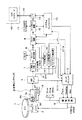
2.ディスクドライブ装置の構成
続いてDVD−RAMに対応して再生が可能とされるディスクドライブ装置の構成例について、図1のブロック図を参照して説明する。なお、本実施の形態のディスクドライブ装置の実際としては、DVD−RAMの再生のみに限定されるものではなく、DVD−ROMの再生も可能とされている。また、DVDだけではなく、CD−DA(Digital Audio)及びCD−ROMの再生も可能とされる。
但しここでは、説明の便宜上、主としては、DVD−RAMを再生するための構成についてのみ説明をおこなっていくこととする。但し実際には、以降説明する各機能回路部において、ディスク種別に応じて、再生信号処理系を切り換えたり、また、所要の再生パラメータを変更したりすることで、上記した各ディスクの再生が可能とされているものである。
【0034】
ここでの光学ディスク1は、上記したDVD−RAMとされる。この光学ディスク1は、図示しないターンテーブルに載置され、スピンドルモータ2によって回転制御される。
【0035】
ここで、DVD−RAMに対する回転制御方式としては、いわゆるZCAV(Zoned Constant Angular Velocity)が採用される。ZCAVは、周知のように、先ずディスクフォーマットとして、ディスクを半径方向に複数ゾーンに分割し、各ゾーンの1トラックあたりのセクタ数を外周方向に従って増加させるようにしておく。そして、各ゾーン内では、CAV(角速度一定:Constant Angular Verocity)で回転制御を行うようにされるが、線速度をディスク全面でほぼ一定とするように、CAVの回転速度は外周ゾーンに行くのに従って低速となるように制御されるものである。
【0036】
光学ピックアップ3では、レーザダイオード30によって、光学ディスク1の信号面にレーザ光を照射して、フォトディテクタ37によって上記信号面からの反射光を検出することで、光学ディスク1に記録されているデータの読み出しを行う。
【0037】
また、光学ピックアップ3においてレーザ光の出力端である対物レンズ34は二軸機構3aによってトラッキング方向及びフォーカス方向に移動可能に保持されている。2軸機構3aには、対物レンズ34を光学ディスク1に接離する方向に駆動するフォーカスコイルと、対物レンズ34を光学ディスク1の半径方向に駆動するトラッキングコイルとが形成されている。
また、光学ピックアップ3全体は、スレッド機構19によって光学ディスク1の半径方向に移動可能とされている。
【0038】
光学ヘッド3内にて検出した反射光はその反射光量に応じた電流信号とされてRFアンプ4に供給され、このRFアンプ4での電流−電圧変換、マトリクス演算処理により、フォーカスエラー信号FE、トラッキングエラー信号TEが生成されるとともに再生情報としてのRF信号、和信号であるPI(プルイン)信号等を生成することができる。
【0039】
RFアンプ4で生成されたフォーカスエラー信号FE、トラッキングエラー信号TEはサーボプロセッサ5にて位相補償、利得調整等の所要の処を施されたのちに駆動回路6に供給され、フォーカスドライブ信号、トラッキングドライブ信号として上述したフォーカスコイルと、トラッキングコイルとに出力される。
さらに上記トラッキングエラー信号TEをサーボプロセッサ5内にてLPF(low pass filter)を介してスレッドエラー信号を生成して、駆動回路6からスレッドドライブ信号としてスレッド機構19に出力される。
これによりいわゆるフォーカスサーボ制御、トラッキングサーボ制御、スレッドサーボ制御が実行される。
【0040】
またサーボプロセッサ5はシステムコントローラ11からの指示に基づいて、フォーカスサーチ動作、トラックジャンプ動作のための信号を駆動回路6に供給し、それに応じた、フォーカスドライブ信号、トラッキングドライブ信号、スレッドドライブ信号を発生させて、光学ヘッド3のフォーカスサーチやトラックジャンプ/アクセス等を実行させる。
【0041】
フォーカスサーチとは、フォーカスサーボ引込のために対物レンズ34をディスク1から最も遠い位置と最も近い位置の間を強制的に移動させながら、フォーカスエラー信号FEの波形として、いわゆるS字カーブを検出する動作である。既に知られているようにフォーカスエラー信号FEとしては、対物レンズ15がディスク1の記録層に対して合焦点位置となるポイントの前後の狭い区間においてS字カーブが観測されるものとなり、そのS字カーブのリニア領域でフォーカスサーボをオンとすることで、フォーカスサーボ引込が可能となる。このようなフォーカスサーボ引込のために、フォーカスサーチが行われるものであり、このためのフォーカスドライブ信号がフォーカスコイルに流され、対物レンズ15の移動が行われる。
【0042】
またトラックジャンプやアクセスの場合には、2軸機構3aによる対物レンズ34のディスク半径方向への移動や、スレッド機構19による光学ヘッド3のディスク半径方向への移動が行われるが、このためのドライブ信号がトラッキングドライブ信号、スレッドドライブ信号としてトラッキングコイルやスレッド機構19に出力されることになる。
【0043】
RFアンプ4にて生成された再生RF信号は、二値化回路7に対して出力されることで二値化され、いわゆるEFMプラス信号となる。そして、このEFMプラス信号は、クロック再生回路8に対して出力される。
クロック再生回路8では、入力されたEFMプラス信号に基づいて、PLL回路などによって、EFMプラス信号に同期した再生クロックCLKを抽出生成して出力する。この再生クロックCLKは、デコード回路やサーボプロセッサ5をはじめとする各種回路における動作クロックとして供給される。クロックが抽出されたEFMプラス信号は、デコード回路9に入力される。また、分岐して、後述するRAM用ブロック14のPID検出部16に対しても入力される。
【0044】
デコード回路9においては、入力されたEFMプラス信号について、EFM-Plus復調(eight to fourteen demodulation Plus:8/16変調に対する復調)を施して、エラー訂正回路10に対して出力する。
エラー訂正回路10においては、バッファメモリ11を作業領域として利用しながら、RS−PC方式に従っての誤り訂正処理を実行する。
【0045】
エラー訂正が行われた2値化データ、つまり再生データは、例えばこの図の場合であれば、エラー訂正処理回路10を介するようにして、バッファメモリ11からデータインターフェイス12を介して転送される。
データインターフェイス12は、外部データバス18を介して接続されるホストコンピュータ40等の外部情報処理装置との通信のために設けられるもので、上述のようにして再生データが転送されてきた場合には、更にこの再生データに対して外部データバス18を介してホストコンピュータ40に転送することができる。
また、データインターフェイス12を介しては、例えば当該ディスクドライブ装置とホストコンピュータ40とのコマンドの送受信も可能とされている。当該ディスクドライブ装置にあっては、このコマンドの送受信は、システムコントローラ13が処理を実行する。
【0046】
システムコントローラ13は全体を制御する部位としてマイクロコンピュータにより形成される。
システムコントローラ11は現在の動作状況、また、ホストコンピュータ40からの指示等に基づいて、各種再生動作のための所要の制御を行うことになる。
【0047】
また、本実施の形態のディスクドライブ装置では、DVD−RAMの再生に対応して、図示するように、RAM用ブロック14が設けられる。
本実施の形態のRAM用ブロック14は、ヘッダ検出部15、PID検出部16、及びランド・グルーブ検出部17を備えて成る。
【0048】
ヘッダ検出部15は、ヘッダ検出を行うための部位とされる。つまり、レーザ光のトレース位置として、DVD−RAMのヘッダ領域を通過しているタイミングを検出する。
この場合、ヘッダ検出部15では、RFアンプにより得られるプルイン信号PI、若しくはプッシュプル信号PPを入力してヘッダ検出を行い、ヘッダ検出信号DT・Hをサーボプロセッサ5及びシステムコントローラ13に対して出力する。
【0049】
サーボプロセッサ5においては、入力されたヘッダ検出信号DT・Hに基づいて、ヘッダを再生しているとされる期間に対応して、トラッキングサーボ制御動作をホールドさせる。つまり、例えばヘッダ領域が検出された直前のトラッキングエラー信号TEの値をホールドして、閉ループによるトラッキングサーボ制御を実行するものである。これによって、トラッキングサーボ制御としては、記録可能領域のトラックに対して1/2トラックピッチ分シフトしているヘッダ領域のトラック(アドレスのピット列)には追随しないようにされ、そのヘッダに続いてトレースすべきランド・トラック又はグルーブ・トラックのトレースを適正かつ良好に実行できることになる。
【0050】
また、システムコントローラ13では、記録再生可能領域とヘッダ領域とのそれぞれに適合させるようにして、所定の再生パラメータについての切り換え制御を実行可能とされている。この制御は例えばデコード回路9をはじめとする所要の機能回路部に対して再生パラメータ切り換えのための制御信号を出力することで行われる。
そして、システムコントローラ13は、ヘッダ検出部15から入力されたヘッダ検出信号DT・Hに基づき、ヘッダ領域を再生しているとされる期間においては、ヘッダ領域に対応した再生用パラメータへの切り換えが行われるように制御を実行する。
【0051】
PID検出部16では、ヘッダ領域に記録された物理アドレスである、PID(1,2,3,4)を検出する。このために、PID検出部16では、アドレスマークAMを検出して、その検出に基づいて、PID信号をデコード回路9に対して出力する。デコード回路9では、このEFMプラス復調処理の過程において、入力されたPID信号についてデコードを行い、PIDとしてのデータを得る。このようにして取得したPIDを利用することで、例えばデコード回路9及びシステムコントローラ13等においては、ヘッダ領域に続く記録可能領域の物理アドレスを認識することが可能になる。
【0052】
また、図10によっても説明したように、DVD−RAMでは、トラックを1周するごとにランドとグルーブが交代する。このため、再生時にあっては、現セクタの記録可能領域としてはランド/グルーブの何れであるのかを検出し、その検出結果に基づいて、例えばランドとグルーブとに対応させてトラッキングサーボ制御で利用されるトラッキングエラー信号TEの極性を反転させることが必要となる。
そして、このランド/グルーブについての検出を行うのがランド/グルーブ検出部17とされる。この場合には、ランド/グルーブ検出部17は、例えばRFアンプ4にて生成したとされるプッシュプル信号PPを入力するようにされる。
【0053】
1つのセクタにおいてランド・トラックをトレースする場合と、グルーブ・トラックをトレースする場合とでは、プッシュプル信号PPは、セクタのヘッダ領域を検出したときには、PID1,2のピット列と、PID3,4のピット列とで、検出波形が互いに反転する。そして、その反転パターンとして、正極性→負極性の順となるのか、或いは負極性→正極性の順となるのかについては、そのヘッダに続くトラックが、ランド・セクタとグルーブセクタの何れとなるのかによって一義的に決まる。そこで、ランド/グルーブ検出部17では、入力されたプッシュプル信号PPについて、上記したヘッダ領域に対応する波形の反転のパターンを検出し、その検出結果に基づいて、ランド又はグルーブであることを示す検出信号を生成する。この検出信号は、例えばサーボプロセッサ5が入力して、前述したようにトラッキングエラー信号TEの極性を適正タイミングで反転させるのに利用する。
なお、ランド/グルーブ検出の方法、構成はほかにも各種考えられ、例えばPIDのデコード結果によっても検出可能であるし、ディスク回転の周期性からも判定することができる。従って、ランド/グルーブ検出部17としては、上記した構成に限定されるものではない。
【0054】
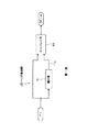
また、ここでDVD−RAMの再生に対応した光学系の構成例について説明しておく。
図2は、光学ピックアップ3における光学系の構成を示している。
この図に示す光学系としては、レーザーダイオード30から出力されるレーザービームは、コリメータレンズ31で平行光にされた後、ビームスプリッタ33に入射する。ビームスプリッタ33の入射光は、光学ディスク1側に90度反射され、更に対物レンズ34を透過することで、収束される状態で光学ディスク1に照射される。
光学ディスク1にて反射された反射光は、対物レンズ34を介してビームスプリッタ33に入射し、そのまま透過して集光レンズ35に達する。そして集光レンズ35で集光された後、円筒レンズ(シリンドリカルレンズ)36を介してフォトディテクタ37に入射される。
【0055】
ここで、レーザーダイオード30は前述したように、DVDに準拠したHDレイヤーの再生を可能とすることを前提として、例えば中心波長が650nmのものとされ、対物レンズ34はNA=0.6とされているものである。
【0056】
また、図3に、フォトディテクタ37の構造例を示す。
この場合のフォトディテクタ37としては、図示するように、少なくとも検出部A,B,C,Dから成る4分割ディテクタを備えて成る。このフォトディテクタ37における4つの検出部A,B,C,Dは、図示する配列形態とされると共に、図の左側に示される記録トラックとの位置関係が得られる方向によって配置される。
なお、以降においては、検出部A〜Dにて得られる検出信号については、それぞれ検出信号A〜Dと表記する。
【0057】
本実施の形態では、後述するヘッダ検出のためにプルイン信号PIを利用する構成を採り得るが、このプルイン信号PIについては、図において等価回路的に示すように、検出部A,B,C,Dの出力である検出信号A,B,C,Dを利用してPI=(A+B+C+D)の演算によって生成することが可能である。
【0058】
また、DVD−RAMにあっては、トラッキングサーボ制御としていわゆるプッシュプル方式が採られる。この方式ではプッシュプル信号PPを利用してサーボ制御を行うが、このプッシュプル信号PPを生成する場合は、図においてこれも等価回路的に示すように、検出部A,B,C,Dの出力である検出信号A,B,C,Dを利用して、差動アンプにより、PP=(A+D)−(B+C)の演算を行うことにより生成することができる。なお、DVD−ROMにあっては、位相差法が利用される。
また、フォーカスエラー信号FEは、演算のための等価回路図は示していないが、検出信号A,B,C,Dを利用して、FE=(A+C)−(B+D)の演算により生成することができる。
なお、上記各信号を生成するための演算は、実際にはRFアンプ4において行われる。
【0059】
3.ヘッダ検出部の構成
3−1.第1例
本実施の形態のディスクドライブ装置としては、図1に示したRAM用ブロック14内のヘッダ検出部15の構成に特徴を有する。そこで以降において、本実施の形態としてのヘッダ検出部15の構成について説明していくこととする。本実施の形態のヘッダ検出部15の構成としては、第1例〜第3例までの3例を挙げる。
【0060】
先ず第1例のヘッダ検出部15の構成及び動作について説明する。
図4のブロック図は、第1例としてのヘッダ検出部15の構成を示している。
この図に示すように、第1例としてのヘッダ検出部4では、RFアンプ4にて生成されるプルイン信号PIを入力する。確認のために記しておくが、プルイン信号PIは、図3にて説明したように、フォトディテクタ37の検出部A,B,C,Dの各出力である検出信号A,B,C,Dについて、
PI=(A+B+C+D)
で表される演算によって生成される信号であり、ディスク信号面から反射される全反射光量を示す。
【0061】
このプルイン信号PIは、積分器51に対して入力されると共に、分岐してコンパレータ52に対して比較対象信号として入力される。
積分器51は所定の時定数を有しており、入力されたプルイン信号PIのレベルをほぼ平均化する。そして、このプルイン信号PIについての積分出力が、コンパレータ52の閾値THとして入力される。
【0062】
コンパレータ52においては、比較対象信号として入力されたプルイン信号PIのレベルを閾値THと比較し、プルイン信号PIのレベルが閾値THを越えていないときにはLレベルで、越えたときにはHレベルとなる信号を出力する。この出力信号が、ヘッダ検出信号DT・Hとされ、Hレベルの区間がヘッダ領域の区間に対応していることを示す。
【0063】
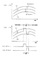
図5のタイミングチャートは、上記図4に示す構成によるヘッダ検出部15の動作を示している。
DVD−RAMとしての光学ディスク1を再生している際に得られるプッシュプル信号PIとしては、図5(a)に示すものとなる。即ち、ディスクのヘッダ領域と記録可能領域とでは光反射率が異なっており、ヘッダ領域のほうが光反射率が高い。このため、例えば図5(a)における期間t1〜t2、t3〜t4、t5〜t6、t7〜t8のように、ヘッダ領域を通過する期間に応じては、或るほぼ決まった値程度にまで信号レベルが高くなる。これに対して、期間t2〜t3、t4〜t5、t6〜t7のように、記録可能領域を通過している際には、ヘッダ領域通過時よりも低いとされる、ほぼ決まったレベルとなる。
また、記録可能領域としては、データが記録済みとされている場合と未記録とされている場合とで光反射率が異なっており、記録済み状態のほうが、未記録状態の場合よりも光反射率は低くなる。このため、例えば図5(a)における期間t2〜t3と、t6〜t7を比較して分かるように、記憶可能領域が記録済みとされている場合よりも、未記録の状態の場合のほうが、プルイン信号PIとしては、高いレベルが得られている。
【0064】
そして、上記プルイン信号PIを入力する積分器51の出力である閾値THは、図5(b)に示される。この図から分かるように、積分器51の時定数が比較的大きいものとされていることで、閾値THとしては、図5(a)に示すプルイン信号PIのレベルをほぼ平均化したような滑らかな波形となる。つまり、プルイン信号PIにおいてヘッダ領域に対応する突出したレベルが平坦化されたうえで、記録可能領域に対応するプルイン信号PIのレベルよりもほぼ一定レベル増加しているような波形となるものである。
また、上記もしたように、プルイン信号PIとしては、セクタにおける記録可能領域が記録済みの場合には低レベルで、未記録の場合にはこれよりも高いレベルとなるのであるが、閾値THは積分出力であることから、この閾値THもまた、図5(b)に示すように、記録済みの記録可能領域を含むセクタを通過している期間t1〜t5においては低レベルで、未記録の記録可能領域を含むセクタを通過している期間t5以降においてはより高いレベルに変化するものとなる。つまり、記録可能領域が記録済みである場合と未記録である場合とに応じたプルイン信号PIの平均レベルの変動に追随するようにして、閾値THのレベルも変動するようにされているものである。
【0065】
そして、コンパレータ52においては、図5(c)に示すようにして入力されるプルイン信号PIと閾値THについて比較を行うことになる。なお、図5(c)においては、閾値THは破線により示している。
この図から分かるように、閾値THのレベルは、プルイン信号PIにおいて記録可能領域を通過しているときのレベルよりも高く、かつ、ヘッダ領域を通解しているときのレベルよりも低いものとなる。
従って、コンパレータ52の出力であるヘッダ検出信号DT・HがHレベルとなるのは、図5(d)に示されるように、ほぼちょうどヘッダ領域を通過しているとされる期間t1〜t2、t3〜t4、t5〜t6、t7〜t8となるものである。
【0066】
例えば、図14及び図15により説明した従来のヘッダ検出のための構成では、閾値(th1,th2)が固定値とされていたことから、検出のための源信号であるプッシュプル信号PPのオフセットには追随することができず、図16により説明したような誤検出が発生する確率は相応に高いものであった。
これに対して、上記図4及び図5により説明したヘッダ検出の構成であれば、検出のための源信号であるプルイン信号PIに対してオフセット的なレベル変動が生じたとしても、閾値THは、このレベル変動に追随して、ほぼ常に適正なレベルを維持することが可能になる。従って、誤検出の発生を従来のばあいよりも大幅に抑制することが可能となるものである。
【0067】
そして、例えばサーボプロセッサ5は、入力されるヘッダ検出信号DT・HがHレベルとなっているホールド期間としてのタイミングで、トラッキングサーボ制御をホールドするのであるが、上記したように、本実施の形態では、ヘッダ検出がより正確に実行されていることから、トラッキングサーボ制御のホールド動作も、実際のヘッダ領域の通過に応じて、より正確に実行されることになる。
【0068】
3−2.第2例
続いて本実施の形態の第2例としてのヘッダ検出部15について説明する。
図6は、第2例としてのヘッダ検出部15の構成を示している。この第2例にあっても、検出のために利用する源信号としてはプルイン信号PIとなる。
【0069】
この場合、RFアンプ4から出力されたプルイン信号PIは、微分器61に対して入力される。そして、この微分器61により微分波形とされたプルイン信号PI−1は、第1積分器62及び第2積分器63に対して入力される。
【0070】
ここで、第1積分器62と第2積分器63においては、それぞれ異なるとされる所定の時定数が設定されており、その大小関係としては、第1積分器62の時定数のほうが、第2積分器63の時定数よりも小さなものとなっている。
第1積分器62からの積分出力PI−2は、比較対象入力としてコンパレータ64に対して入力され、第2積分器63からの積分出力PI−3は、加算器65に対して入力される。
【0071】
加算器65では、積分出力PI−3に対して、所定のレベルのオフセットが与えられるように、例えば予め設定されたオフセット値を加算する。そして、この積分出力PI−3にオフセットを与えることで得られるレベルの信号を閾値THとしてコンパレータ64に入力する。
コンパレータ64では、第1積分器62からの積分出力PI−2のレベルと閾値THとを比較して、この場合にも、閾値THよりも積分出力PI−2のレベルが高いときにはHレベルとされ、低いときにはLレベルとなるヘッダ検出信号DT・Hを出力する。
【0072】
次に、図7のタイミングチャートにより、上記図6に示した構成によるヘッダ検出部15の動作を説明する。
ここで、ヘッダ検出のための源信号として入力されるプルイン信号PIは、図7(a)に示されているが、ここでは、先に図5(a)に示したのと同一の波形を示している。
【0073】
このプルイン信号PIを入力して微分する微分器61の微分出力PI−1は、図7(b)に示すように、プルイン信号PI(図5(a))の波形(レベル)変化が大きいとされる、ヘッダ領域の開始位置と終了位置において微分パルスが得られる波形となる。例えば、時点t1のヘッダ領域の開始位置ではプルイン信号PIが急峻に立ち上がるために、これに応じて、微分出力PI−1は正極性の方向に微分パルスが得られ、これに続く時点t2のヘッダ領域の終了位置ではプルイン信号PIが急峻に立ち下がるのに応じて、微分出力PI−1は負極性の方向に微分パルスが得られることになる。
【0074】
上記時点t1,t2については、その前後の記録可能領域が記録済みとされて、その反射率が低い状態の場合であるが、例えば時点t7及びt8の場合のように、その時点の前後の記録可能領域が未記録である場合にも、ヘッダ領域の開始/終了位置に対応する時点t7及び時点t8のタイミングで、図7(b)に示すようにして、時点t1,t2の場合と同様のタイミングで正負の微分波形が得られる。但し、時点t1,t2のときに対して、時点t7,t8のときのほうがプルイン信号PIのレベル変化量が小さいために、これに対応して得られる微分パルスも、時点t1,t2のときよりも、時点t7,t8のときのほうがレベルが小さいものとなってはいる。
そして、このような波形の微分出力PI−1が、第1積分器62,第2積分器63に対して入力される。
【0075】
第1積分器62から出力される積分出力PI−2は、第1積分器62の時定数設定によって、図7(c)に示すようにして、微分出力PI−1の微分パルスを積分することで、この微分パルスの立ち下がりが緩やかなものとなるようにし、その幅を拡大させている。なお、この拡大幅は、ほぼヘッダ領域の通過期間(ホールド期間)に対応する期間t1〜t2に対応したものとされ、第1積分器62の時定数によって決定される。
【0076】
また、第2積分器63から出力される積分出力PI−3は、微分出力PI−1を微分パルスを除去するようにして、そのレベルを平均化した波形となる。そして、結果的には、図7(c)に示されるように、積分出力PI−2における拡大された微分パルスを除去するようにしてそのレベルを平均化した波形となる。また、この積分出力PI−3のレベルとしては、実際には、積分出力PI−2の平坦部分とされるレベルに対して若干増加させたものとなる。
【0077】
ここで、例えばコンパレータ64としては、閾値THとして積分出力PI−3を利用して積分出力PI−2と比較するようにしても、ヘッダ領域の検出は可能とされる。但し、積分出力PI−3のレベルは、積分出力PI−2の平坦部分のレベルに対する増加分が比較的僅かなものであることから、例えば積分出力PI−2の平坦部分において或る程度のレベル変動が現れた波形部分を誤検出してしまう可能性が生じる。
そこで、本実施の形態においては、ヘッダ検出の信頼性を向上させるために、積分出力PI−3に対してオフセットを与えたレベルの信号を閾値THとしている。この閾値THもまた、図7(c)に示されている。
この図から分かるように、閾値THは、積分出力PI−3に対して増加方向のオフセットが与えられたレベルを有しており、これによって、積分出力PI−2の平坦部分の波形が閾値TH以上となることが無いようにしているものである。
【0078】
そして、コンパレータ64において、図7(c)に示す積分出力PI−2と閾値THとを比較する。ここで、例えば、期間t1〜t2に対応して得られている、積分出力PI−2の正極性の拡大パルス波形は、閾値THのレベルを越えていることから、このタイミングで、図7(d)に示すようにしてHレベルのヘッダ検出信号DT・Hが出力されることになる。つまり、ヘッダ領域であることを示す信号を出力するものである。また、期間t3〜t4、t5〜t6についても同様の動作によって、Hレベルのヘッダ検出信号DT・Hが得られていることで、適正にヘッダ領域を検出している。
そしてこの場合にも、ヘッダ検出信号DT・HがHレベルとされる期間がホールド期間に対応し、このホールド期間にわたって、トラッキングサーボ制御がホールドされる。
【0079】
このような構成では、ヘッダ検出に利用される源信号を微分したうえで、この微分波形に基づいてヘッダ検出を行うようにされている。ヘッダ検出の基となる信号を微分するということは、ヘッダ領域と記録可能領域との境界に対応する源信号のレベルの変化を強調していることにほかならず、従って、この強調されたレベル変化を利用して信号レベルの比較を行うようにすれば、その検出精度はより高いものとなる。
また、この第2例にあっても、閾値THとしては、源信号を微分した微分出力PI−1を積分していることで、結果的には、コンパレータ64に対して入力される積分出力PI−2の平坦波形部のレベル変動に追随させたレベルを得ることができているものである。
【0080】
但し、第2例の構成にあっては、図7に示すように、その前後の記録可能領域が未記録エリアとされている期間t7〜t8においては、積分出力PI−2の拡大された微分パルス波形のピークレベルが小さくなることから、この期間t7〜t8においてヘッダ検出信号DT・HがHレベルとなる期間は、ヘッダ領域の終了位置に対応する時点t8よりも前の時点で終了してしまっている。つまり、この場合には、ヘッダ検出信号DT・HがHレベルとなる期間長が対応するとされるホールド期間は、実際よりも短いものとなってしまっている。
そこでこのような場合に対応して、例えばこの第2例にあっては、ヘッダ検出信号DT・HがHレベルに立ち上がった時点から計時を開始し、この計時開始時点から例えば現在の線速度でヘッダを通過するとされる時間が経過した時点までをホールド期間とするようにされる。このようにすれば、期間t7〜t8のようなヘッダ検出信号DT・Hが出現したとしても、ヘッダ領域通過時に対応した適正タイミングでトラッキングサーボ制御をホールドさせることが可能となるものである。
【0081】
3−3.第3例
続いて第3例としてのヘッダ検出部15の構成について説明する。
図8のブロック図は、第3例としてのヘッダ検出部15の構成を示している。この第3例にあっては、図示するように、源信号としてはプルイン信号PIではなく、プッシュプル信号PPとされる。プッシュプル信号PPは、図3にも示したように、トラック方向に沿ってフォトディテクタを2分割した検出部において得られる検出信号の差分を取ることで得られる。
【0082】
当該ヘッダ検出部15に入力されたプッシュプル信号PPは、積分器71に対して入力されると共に、コンパレータ73,75の各々に対しても分岐して入力される。
積分器71においては、入力されたプッシュプル信号PPについて積分して出力する。
この積分器71に入力されるプッシュプル信号PPとしては、例えば時間経過に応じて図9(b)に示す変化を有する波形となる。つまり、プッシュプル信号PPは、記録可能領域に対応しては平坦な波形となり、ヘッダ領域に対応しては、正極性と負極性の方向で交互に反転するパターンの波形が得られる。なお、先にも述べたが、この極性の反転は、PID1,2のピット列と、PID3,4のピット列とがグルーブ中心線から互いに1/2トラックピッチずれるようにして配置されていることに起因している。また、ヘッダに続くトラックが、ランド・セクタとグルーブセクタの何れとなるのかによって、その反転パターンが、正極性→負極性の順となるのか、或いは負極性→正極性の順となるのかが決まる。
【0083】
そして、上記プッシュプル信号PPを積分する積分器71の積分出力Skは、図9(a)に示されるものとなる。これは、図9(b)に示すプッシュプル信号PPの波形と比較して分かるように、ヘッダ領域において得られる反転パターンが平均化されるようにしてほぼ除去された波形となるものである。
【0084】
上記のような波形とされた積分器71の積分出力Skは、分岐して加算器72,74に対して入力される。そして、加算器72においては、積分出力Skのレベルに対して第1オフセットレベルを加算し、加算器74においては、積分出力Skのレベルに対して第2オフセットレベルを加算する。第1オフセットレベルは、所定のプラス方向にオフセットを与える値とされ、第2オフセットレベルは、所定のマイナス方向にオフセットを与える値とされる。そして、加算器72の出力が第1の閾値TH1とされ、加算器74の出力が第1の閾値TH2とされる。
【0085】
図9(a)には、先に説明した積分出力Skと共に閾値TH1,TH2が示されている。上記説明のとおり、閾値TH1は、積分出力Skに対して第1オフセットレベル分、増加方向にシフトした波形を有することとなり、一方の閾値TH2は、積分出力Skに対して第2オフセットレベル分、減少方向にシフトした波形を有することとなる。
【0086】
コンパレータ73においては、図8に示すように、プッシュプル信号PPを比較対象として入力し、加算器72から出力される閾値TH1との比較を行う。これについては、図9(b)に示されている。即ち、コンパレータ73では、プッシュプル信号PPの波形として、ヘッダ領域において出現する正極性の略矩形波形を検出対象としており、この正極性の略矩形波形(検出波形)が閾値TH1を越えた状態が得られたときに、図9(c)に示すようにして、ヘッダ検出信号DT・H−1としてHレベルを出力する。このHレベルのヘッダ検出信号DT・H−1は、ヘッダ領域におけるPID1,2のピット列と、PID3,4のピット列の何れか一方の領域を検出したことを示している。
【0087】
これ対して、コンパレータ75は、図8に示されるように、プッシュプル信号PPを比較対象として入力し、加算器72から出力される閾値TH2との比較を行うようにされている。そして、これについても図9(b)に示されている。
コンパレータ73では、プッシュプル信号PPにつき、ヘッダ領域において出現する負極性の略矩形波形(検出波形)を検出対象としている。そして、この負極性の略矩形波形(検出波形)が閾値TH2を越えた状態が得られたときに、図9(d)に示すようにして、ヘッダ検出信号DT・H−2としてHレベルを出力する。このHレベルのヘッダ検出信号DT・H−2は、例えばヘッダ検出信号DT・H−1として、ヘッダ領域におけるPID1,2のピット列を検出したものであるとすれば、他方のPID3,4のピット列を検出したことを示していることになる。
そして、このヘッダ検出信号DT・H−1の立ち上がり時点から、DT・H−2の立ち下がり時点までの期間がホールド期間となり、この期間にわたってトラッキングサーボ制御をホールドさせれば、実際のヘッダ領域に応じた正確な動作を得ることができる。
【0088】
そして、このような構成においても、閾値TH1,TH2は源信号であるプッシュプル信号PPを積分した信号に基づいて生成されることから、プッシュプル信号PPにオフセットが与えられたとしても、このレベル変動に追随したレベルを有することになる。従って、この構成においてもヘッダ検出を従来より高精度で行うことができるものである。
また、この構成の場合には、ヘッダ領域においてPID1,2のピット列とPID3,4のピット列とに応じて反転する波形部分を個別に検出できるようになっているために、各検出出力であるヘッダ検出信号DT・H−1,DT・H−2をそれぞれ利用することで、より詳細なヘッダ検出を行い、これに基づいた細かな所定の動作制御等を実行させるようにもすることができる。
【0089】
なお、上記実施の形態としては、DVD−RAMを再生する場合を例に挙げているが、再生対象となるディスクの種別はこれに限定されるものではなく、例えば周回トラック上で光反射率が異なる複数領域を有しているトラックフォーマットのディスクでありさえすれば本発明の適用は可能である。また、ここでは、再生時における動作として説明しているが、記録時においても、同様に、周回トラック上で光反射率が異なる複数領域のうちの特定領域を検出する必要のある場合には本発明を適用できる。
【0090】
【発明の効果】
以上説明したように本発明は、例えばヘッダ領域と記録可能領域のように、光反射率、つまり、反射光量に基づいて検出される信号の振幅が異なるとされる複数の信号面領域を有するディスクに対応するディスクドライブ装置において、上記ヘッダ領域のような特定の信号面領域を検出するのにあたって、プルイン信号(反射光量検出信号)を積分して得られる積分出力を閾値として、この閾値とプルイン信号とを比較した結果に基づいて、ヘッダ領域を検出するように構成される。
この構成であれば、閾値としては固定ではなく、プルイン信号に重畳するオフセットによるレベル変動に追随して変動することになるため、プルイン信号のオフセットに関わらず、従来よりも的確にヘッダ検出を行うことが可能となるという効果を有している。
【0091】
また、本発明としては、ヘッダ領域を検出するのにあたり、プルイン信号を微分して得られる微分出力を第1の積分手段(積分器)により積分して閾値を生成し、この閾値と微分出力とを比較した結果に基づいてヘッダ検出を行うようにもされる。この構成では、積分出力を閾値としていることで、上記した発明の場合と同様に、プルイン信号のオフセットに追随する閾値を得ることが可能とされている。そして更に本発明では、プルイン信号を微分していることから、例えばヘッダ領域と記録可能領域の境界でのプルイン信号のレベル変化を強調した信号を比較対象信号として利用することになり、それだけ、誤検出の可能性も低いものとすることができる。
【0092】
また、上記発明のもとで、閾値生成のための第1の積分手段の時定数よりも小さいとされる所定の時定数による第2の積分手段を設けて、この第2の積分手段を閾値と比較して、検出結果を得るようにされる。
この構成であれば、例えばプルイン信号を微分して得られる微分出力の微分パルスの幅を、実際のヘッダ領域の通過期間と同等となるように拡大させることが可能となり、より正確なヘッダ領域の検出を行うことが可能となる。
更に、上記した発明のもとで、第1の積分手段による積分出力のレベルについて所定のオフセットを与えるようにすれば、閾値と比較される信号の記録可能領域(検出対象では無い信号面領域である)に対応する波形部分を誤検出することが防止され、これによっても、ヘッダ領域の検出を更に正確なものとすることができる。
【0093】
また、本発明としては、ヘッダ検出に利用する信号として、例えばプッシュプル信号といわれる、ディスク信号面からの反射光を分割受光して得られる検出信号に基づいて得られる反射光検出信号を利用するようにもされる。そしてこの場合には、上記プッシュプル信号を積分した積分出力について所定レベルのオフセットを与えたレベルを閾値として、この閾値とプッシュプル信号とについて比較を行うことでヘッダ領域を検出するようにされる。
プッシュプル信号は、例えばヘッダ検出にあたって、ヘッダ領域に記録されたピット列の配置に応じて波形が反転するために、この反転パターンをより詳細なヘッダ検出に利用できるという利点は有するのであるが、その一方で、各種要因による信号レベルのオフセットが生じやすい。
しかし、本発明によっても、プッシュプル信号の積分出力に基づいて閾値を生成していることから、閾値としては、プッシュプル信号のオフセットに追随したレベルを維持でき、従ってこの場合にも、従来よりも正確にヘッダ検出を行うことができる。
また、上記発明の構成のもとで、ヘッダ領域に対応して得られるプッシュプル信号の波形が反転するのに応じて、一方のの反転波形について検出を行う系と、他方の反転波形の検出を行う系との2系統の検出回路系を備えるようにすれば、単にヘッダ領域の区間を検出するだけではなく、ヘッダ領域内のデータ列の配置パターンの変化も識別することを実現でき、これにより、結果的にはヘッダ検出の信頼性をより高いものとすることが可能になる。
【図面の簡単な説明】
【図1】本発明の実施の形態としてのディスクドライブ装置の構成例を示すブロック図である。
【図2】本実施の形態のディスクドライブ装置における光学系の構成例を示す概念図である。
【図3】本実施の形態のディスクドライブ装置におけるフォトディテクタ及び信号の生成方法を示す説明図である。
【図4】本実施の形態のディスクドライブ装置に備えられるヘッダ検出部の第1例としての構成を示すブロック図である。
【図5】第1例としてのヘッダ検出部の動作を示すタイミングチャートである。
【図6】本実施の形態のディスクドライブ装置に備えられるヘッダ検出部の第2例としての構成を示すブロック図である。
【図7】第2例としてのヘッダ検出部の動作を示すタイミングチャートである。
【図8】本実施の形態のディスクドライブ装置に備えられるヘッダ検出部の第3例としての構成を示すブロック図である。
【図9】第3例としてのヘッダ検出部の動作を示す説明図である。
【図10】DVD−RAMについて、ディスク全体に関してのトラックフォーマットを示す説明図である。
【図11】DVD−RAMのトラックフォーマットとして、1セクタ内のトラック配列をを概念的に示す説明図である。
【図12】DVD−RAMのトラックフォーマットとして、1セクタを形成するデータ構造を概念的に示す説明図である。
【図13】1セクタ内のデータ領域に記録されるデータの構造を示す説明図である。
【図14】従来例におけるヘッダ検出のための構成例を示すブロック図である。
【図15】図14に示す構成の回路によるヘッダ検出動作を示す説明図である。
【図16】図14に示す構成の回路によるヘッダ検出動作として誤検出が行われた場合を示す説明図である。
【符号の説明】
1 光学ディスク、2 スピンドルモータ、3 光学ピックアップ、3a 二軸機構、4 RFアンプ、5 サーボプロセッサ、6 駆動回路、10 エラー訂正回路、11 バッファメモリ、12 データインターフェイス、13 システムコントローラ、14 RAM用ブロック、15 ヘッダ検出部、16 PID検出部、17 ランド・グルーブ検出部、18 外部データバス、19 スレッド機構、30 レーザダイオード、34 対物レンズ、37 フォトディテクタ、40 ホストコンピュータ、51 積分器、52 コンパレータ、61 微分器、62,63,71 積分器、64、73,75 コンパレータ、72,74 加算器[0001]
BACKGROUND OF THE INVENTION
The present invention relates to a disk drive device capable of recording or reproducing corresponding to an optical disk-shaped recording medium, and in particular, an optical disk having a plurality of signal surface areas with different amplitudes of detection signals as reflected light information. The present invention relates to a disk drive device corresponding to a recording medium.
[0002]
[Prior art]
A DVD (Digital Versataile Disc or Digital Video Disc) is known as a disk medium. As this DVD, in addition to reproduction-only, which is called DVD-ROM, which cannot record data, a DVD-RAM capable of rewriting data has been developed and has become widespread. The DVD-RAM performs data recording by forming recording pits by a so-called phase change method.
[0003]
As a track format of DVD-RAM, a recording track on which data is recorded and reproduced is circular.directionAre divided by units called sectors. A header area exists at the head of the recordable area as a sector.
Here, the header area is an area where data is recorded by a pit row, and the recordable area is an area where data can be rewritten by a phase change method. That is, the data recording method is different between the header area and the recordable area, and the amount of reflected laser light is also different depending on this.
[0004]
Although detailed description is omitted here, four addresses PID1, PID2, PID3, and PID4 indicating physical addresses are recorded in the header area. The pit rows of PID1 and PID2 are arranged with a 1/2 track pitch shifted in the outer circumferential direction from the center line of the groove track, and PID3 and PID4 are arranged with a 1/2 track pitch shifted in the inner circumferential direction. . In other words, the track position in the disc radial direction is shifted by 1/2 track pitch between the header area and the recordable area. The DVD-RAM employs a so-called land / groove recording method in which recording is performed on both lands and grooves.
[0005]
For this reason, in a disk drive device compatible with DVD, for example, when a laser beam tracing a track during data reproduction passes through the header area, it is necessary to hold the tracking servo. In other words, if the tracking servo is held when passing through the header area, the trace position of the laser beam in the tracking direction is prevented from being shifted from the track of the recordable area.
Further, as described above, since the recording method is different in each area, it is necessary to change various parameters in the reproduction signal processing circuit system.
[0006]
In order to execute processing such as tracking servo control hold and various reproduction parameter changes as described above at an appropriate timing corresponding to the passage of the header area, the timing at which the laser beam passes the header area must be detected. Is even more necessary.
Hereinafter, the detection of the timing at which the laser light passes through the header area is also simply referred to as “header detection”.
[0007]
The header detection as a conventional example will be described with reference to FIGS.
FIG. 14 shows an example of the configuration of the header detection circuit.
The
[0008]
In this case, the push-pull signal PP output from the push-pull
[0009]
Here, as a waveform of the push-pull signal PPL, for example, when a header is properly detected, the waveform is as shown in FIG. In other words, in the header section that is supposed to pass through the header area, according to the detection of the pit rows of
[0010]
In FIG. 14, the push-pull signal PPL is branched and input as a comparison target to the
[0011]
Then, the
Similarly, the
[0012]
In this way, the detection signal DT · h1 and the detection signal DT · h2 are at the H level corresponding to the first half period and the second half period of the header section, so that the period as the header section is detected. That is, header detection is performed.
[0013]
[Problems to be solved by the invention]
However, in the case of the above-described header detection configuration, detection with a fixed threshold and using a push-pull signal is likely to cause erroneous detection. This point will be described with reference to FIG.
For example, detracking due to eccentricity of the disc, fluctuation of the laser beam spot position,WoundWhen a defect such as dust or the like occurs, an unnecessary offset level may be given to the push-pull signal itself as shown by the push-pull signal PPL in FIG. In this case, a state in which an offset is applied due to the tendency of the level to increase is shown.
For example, when the push-pull signal PPL to which such an offset is given is compared with the threshold values th1 and th2 in the
[0014]
Conversely, in the case shown in FIG. 16A, an offset is given to the positive level with respect to the push-pull signal PPL. For this reason, in the case where the level of the threshold value th1 is exceeded not only in the first half of the original header section but also in the section A other than the header section, for example, as shown in FIG. An erroneous detection in which an H level is output in a section other than that also occurs.
[0015]
As described above, since the header detection is used for timing control of processing such as tracking servo hold corresponding to passage of the header area and change of the reproduction parameter, the higher the frequency of erroneous detection, the higher the reproduction performance. Reliability will be reduced. Therefore, it is required that detection of a specific area on the disk, such as this header detection, be performed as well as possible.
[0016]
[Means for Solving the Problems]
Therefore, the present invention takes the above-mentioned problems into consideration,Optical disc-shaped recording formed by a track in which a sector consisting of a header area in which addresses are recorded by a pit row and a recordable area in which data can be rewritten by a phase change method follows the header area. A reflected light amount detecting means for detecting a total light amount of light reflected by the signal surface of the medium and outputting a reflected light amount detection signal; a differentiating means for performing differentiation on the reflected light amount detection signal to obtain a differential output; and A first integrating means for obtaining a first integrated output by performing integration with a predetermined time constant, an offset means for giving a predetermined offset with respect to the level of the first integrated output, and the differential output , Second integration means for obtaining a second integrated output by performing integration with a predetermined time constant which is smaller than the first integrated output, and the first An offset means for giving a constant offset with respect to the level of the integrated output, and using the level of the first integrated output to which the offset is given as a threshold, the threshold is compared with the level of the second integrated output, and Comparator means for outputting a specified level when the level of the second integrated output is greater than the threshold value, and timing is started according to the time point when the output of the specified level is started from the comparator means. Based on the signal obtained by detecting the light reflected on the signal surface of the optical disk-shaped recording medium, and the hold period setting means for setting as a hold period until the time when it is supposed to pass through the header at speed Tracking servo control is executed based on the generated tracking error signal. , And holding the tracking error signal value immediately before the hold period, it was decided to constitute a disc drive device and a tracking servo control means for performing tracking servo control by the closed loop.
[0019]
In the above configuration, the signal that becomes the basis for detecting a specific signal surface area is a reflected light amount detection signal obtained by detecting the total reflected light amount from the disk signal surface. In this case, first, the reflected light amount detection signal is differentiated. A specific signal surface area is detected by comparing the differential output with a signal level based on the integrated output of the differential output and a signal level based on the threshold and the differential output.
Therefore, even in this configuration, since the threshold is integrated based on the reflected light amount detection signal, it is not a fixed value, for example, it follows the level of the reflected light amount detection signal whose offset level varies depending on various factors. It becomes.
Further, in this case, a comparison is made between an integrated value threshold obtained by integrating the differential output and a differential output obtained by differentiating the reflected light amount detection signal. That is, the differential output is used as an input for comparison. In other words, the detection is performed by using the portion where the change in the reflected light amount detection signal waveform corresponding to the detection of the specific signal surface area is emphasized, and as a result, the detection with higher accuracy is performed. It is possible.
[0021]
In the above configuration, the reflected light detection signal generated by performing a predetermined calculation based on the detection signal obtained by dividing and receiving the reflected light is used to detect a specific signal surface area. .
Then, by integrating the reflected light detection signal and giving a signal with an offset as a threshold, a comparison is made between the threshold and the level of the reflected light detection signal to output an identification signal.
The reflected light detection signal itself is a vibration whose offset amount fluctuates due to factors such as detracking. For example, the reflected light detection signal is used to generate a threshold value as described above. The threshold value includes the fluctuation component of the offset amount so as to follow the original reflected light detection signal. In other words, when the signal level is compared, the fluctuation of the offset amount of the reflected light detection signal is canceled, and therefore, the specific amount is not affected by the fluctuation of the offset amount of the reflected light detection signal. It is possible to detect the change in the waveform of the reflected light detection signal in accordance with the detection of the signal surface area more accurately.
[0022]
DETAILED DESCRIPTION OF THE INVENTION
Hereinafter, embodiments of the present invention will be described. The disk drive apparatus according to the embodiment of the present invention is configured to be able to reproduce a DVD-RAM. In practice, however, a DVD-ROM, a CD-DA (Digital Audio), a CD-ROM, etc. CD format discs can also be played.
The following description will be given in the following order.
1. DVD-RAM track format
2. Configuration of disk drive device
3. Configuration of header detector
3-1. First example
3-2. Second example
3-3. Third example
[0023]
1. DVD-RAM track format
First, the track format of the DVD-RAM that can be reproduced by the disk drive device according to the embodiment of the present invention will be schematically described with reference to FIGS.
[0024]
The DVD-RAM is a rewritable disc medium based on a so-called phase change method, and currently has a storage capacity of 4.7 GB (unformatted) on one side.
FIG. 10 conceptually shows the structure of the entire disc as a track format of DVD-RAM.
The
The land track and the groove track are connected to each other one by one at a predetermined linear position along the disc radius indicated by an arrow a in the figure, for example, from the disc inner periphery side to the outer periphery side. In this case, one track is formed in a spiral shape.
[0025]
Further, a recording track composed of a land track and a groove track is divided into a plurality of sectors in the circulation direction as shown in FIG. The structure in one sector is shown in FIGS.
[0026]
As shown in FIG. 11, in one sector, a header area is first provided, followed by a recordable area. In the header area, as shown in the figure, a PID indicating a physical address on the disc is recorded by a pit string. The recordable area is an area where data can be rewritten by the phase change method, and the land track and the groove track are alternately arranged along the disk radial direction as shown in the figure. . Further, the land track and the groove track have a meandering shape with a cycle of 232 cycles in one sector, and a so-called wobble is formed. In the DVD-RAM, the clock is recorded by this wobble shape.
[0027]
In the header area, a set of headers is formed with
Such PID arrangement, that is, address arrangement, is called CAPA (Complimentary Allocated Pit Address). When tracing a certain groove track within one sector, a land track adjacent to this groove track is assigned. It shares the address when operating.
By such an address arrangement, for example, crosstalk between addresses of adjacent pit rows is eliminated. Compared with the method of assigning addresses to each of the land track and the groove track, the header length can be halved, and the redundancy can be reduced and the recording capacity can be increased accordingly.
[0028]
Here, taking a set of headers consisting of PID1 (m + N), PID2 (m + N), PID3 (m), and PID4 (m) in FIG. 11 as an example, PID1 (m + N) and PID2 (m + N) The pit rows as PID3 (m) and PID4 (m) are arranged in the inner circumferential direction of the ½ track pitch. They are arranged so as to be displaced.
Depending on PID1 (m + N) and PID2 (m + N), the address position in the sector as the land track (m + N) adjacent to the groove track (m) in the outer circumferential direction is indicated, and PID3 (m), PID4 ( Depending on m), the address position in the sector as the groove track (m) is indicated.
[0029]
FIG. 12 shows the data arrangement structure in one sector.
First, in the header area, there are four
Also, before each of PID2 and PID4, VFO(Variable Frequency Oscillator) 2 and an address mark AM are arranged, and a postamble PA2 is arranged behind the address mark AM.
The address mark AM is used to provide the device with byte synchronization of the subsequent PID and has a predetermined pattern. The postambles PA1 and PA2 are defined as boundary areas.
[0030]
In the recordable area, a gap,
A data area is arranged after the amble PS behind the
[0031]
Following the postamble PA3, a
[0032]
The data recorded in the data area within one sector is composed of 26 frames as shown in FIG. A frame sync is arranged at the head of each frame, and sync numbers of SY0 to SY7 are given to the frame sync as shown in the figure. The position in the frame data can be specified from the context as the sync number.
[0033]
2. Configuration of disk drive device
Next, a configuration example of a disk drive device that can be played back in accordance with the DVD-RAM will be described with reference to the block diagram of FIG. Note that the actual disk drive device of the present embodiment is not limited to DVD-RAM playback, but DVD-ROM playback is also possible. Further, not only DVD but also CD-DA (Digital Audio) and CD-ROM can be reproduced.
However, for convenience of explanation, only the configuration for reproducing a DVD-RAM will be mainly explained. In practice, however, each of the above-described discs can be played back by switching the playback signal processing system or changing the required playback parameters according to the disc type in each functional circuit section described below. It is what is said.
[0034]
The
[0035]
Here, a so-called ZCAV (Zoned Constant Angular Velocity) is adopted as a rotation control method for the DVD-RAM. As is well known, ZCAV first divides a disk into a plurality of zones in the radial direction as a disk format, and increases the number of sectors per track in each zone in the outer circumferential direction. In each zone, rotation control is performed with CAV (Constant Angular Velocity), but the rotation speed of CAV goes to the outer zone so that the linear velocity is almost constant over the entire disk surface. It is controlled so that it becomes low speed according to.
[0036]
In the
[0037]
In the
The entire
[0038]
The reflected light detected in the
[0039]
The focus error signal FE and the tracking error signal TE generated by the
Further, a thread error signal is generated from the tracking error signal TE in the
As a result, so-called focus servo control, tracking servo control, and thread servo control are executed.
[0040]
The
[0041]
Focus search is to detect a so-called S-curve as the waveform of the focus error signal FE while forcibly moving the
[0042]
Further, in the case of track jump or access, the biaxial mechanism 3a moves the
[0043]
The reproduction RF signal generated by the
The clock recovery circuit 8 extracts, generates and outputs a recovery clock CLK synchronized with the EFM plus signal by a PLL circuit or the like based on the input EFM plus signal. The reproduction clock CLK is supplied as an operation clock in various circuits including the decode circuit and the
[0044]
In the
The
[0045]
For example, in the case of this figure, binarized data that has been subjected to error correction is transferred from the
The data interface 12 is provided for communication with an external information processing apparatus such as the
Also, via the
[0046]
The
The
[0047]
Further, in the disk drive device of the present embodiment, a
The
[0048]
The
In this case, the
[0049]
The
[0050]
Further, the
Based on the header detection signal DT · H input from the
[0051]
The
[0052]
Further, as described with reference to FIG. 10, in the DVD-RAM, the land and the groove alternate every time the track goes around. For this reason, at the time of reproduction, it is detected whether the recordable area of the current sector is land / groove, and based on the detection result, for example, it is used for tracking servo control corresponding to land and groove. It is necessary to reverse the polarity of the tracking error signal TE to be performed.
The land /
[0053]
In the case where the land track is traced in one sector and the case where the groove track is traced, the push-pull signal PP detects the pit row of
Various other land / groove detection methods and configurations are conceivable. For example, detection can also be performed based on a PID decoding result, and determination can also be made from the periodicity of disk rotation. Therefore, the land /
[0054]
Here, a configuration example of an optical system corresponding to reproduction of the DVD-RAM will be described.
FIG. 2 shows the configuration of the optical system in the
In the optical system shown in this figure, the laser beam output from the
The reflected light reflected by the
[0055]
Here, as described above, the
[0056]
FIG. 3 shows a structural example of the
As shown in the figure, the
Hereinafter, the detection signals obtained by the detection units A to D will be referred to as detection signals A to D, respectively.
[0057]
In the present embodiment, a configuration using a pull-in signal PI for header detection, which will be described later, can be adopted. However, the pull-in signal PI is detected by the detection units A, B, C, The detection signals A, B, C, and D, which are the outputs of D, can be used to generate PI = (A + B + C + D).
[0058]
In addition, the DVD-RAM employs a so-called push-pull method as tracking servo control. In this method, the servo control is performed using the push-pull signal PP. However, when the push-pull signal PP is generated, the detection units A, B, C, and D are detected as shown in an equivalent circuit in the figure. The detection signals A, B, C, and D that are outputs can be used to calculate PP = (A + D) − (B + C) by a differential amplifier. In the DVD-ROM, a phase difference method is used.
The focus error signal FE is not shown in an equivalent circuit diagram for calculation, but is generated by calculation of FE = (A + C) − (B + D) using the detection signals A, B, C, and D. Can do.
The calculation for generating each signal is actually performed in the
[0059]
3. Configuration of header detector
3-1. First example
The disk drive device according to the present embodiment is characterized by the configuration of the
[0060]
First, the configuration and operation of the
The block diagram of FIG. 4 shows the configuration of the
As shown in this figure, the
PI = (A + B + C + D)
The total reflection light amount reflected from the disk signal surface.
[0061]
The pull-in signal PI is input to the
The
[0062]
In the
[0063]
The timing chart of FIG. 5 shows the operation of the
The push-pull signal PI obtained when reproducing the
In addition, as the recordable area, the light reflectance differs depending on whether the data is recorded or not recorded, and the recorded state is more reflective than the unrecorded state. The rate is low. For this reason, for example, as can be seen by comparing the periods t2 to t3 and t6 to t7 in FIG. 5A, in the case of the unrecorded state, compared to the case where the storable area is recorded, A high level is obtained as the pull-in signal PI.
[0064]
The threshold value TH, which is the output of the
As described above, the pull-in signal PI has a low level when the recordable area in the sector has been recorded, and a higher level when the recordable area has not been recorded. Since this is an integral output, this threshold value TH is also low and unrecorded during the period t1 to t5 passing through the sector including the recorded recordable area, as shown in FIG. 5B. It changes to a higher level after the period t5 passing through the sector including the recordable area. That is, the level of the threshold TH is also changed so as to follow the change in the average level of the pull-in signal PI depending on whether the recordable area has been recorded or not recorded. is there.
[0065]
In the
As can be seen from this figure, the level of the threshold value TH is higher than the level when passing through the recordable area in the pull-in signal PI and lower than the level when passing through the header area. .
Therefore, the header detection signal DT · H, which is the output of the
[0066]
For example, in the conventional configuration for header detection described with reference to FIGS. 14 and 15, since the threshold values (th1, th2) are fixed values, the offset of the push-pull signal PP, which is the source signal for detection, is offset. Therefore, the probability of the erroneous detection described with reference to FIG. 16 is correspondingly high.
On the other hand, in the header detection configuration described with reference to FIGS. 4 and 5, even if an offset level fluctuation occurs with respect to the pull-in signal PI that is a source signal for detection, the threshold value TH is Following this level fluctuation, it becomes possible to maintain an appropriate level almost always. Therefore, the occurrence of erroneous detection can be greatly suppressed as compared with the conventional case.
[0067]
Then, for example, the
[0068]
3-2. Second example
Next, the
FIG. 6 shows the configuration of the
[0069]
In this case, the pull-in signal PI output from the
[0070]
Here, in the
The integration output PI-2 from the
[0071]
The
The
[0072]
Next, the operation of the
Here, the pull-in signal PI input as a source signal for header detection is shown in FIG. 7A. Here, the same waveform as that shown in FIG. Show.
[0073]
The differential output PI-1 of the
[0074]
The time points t1 and t2 are the cases where the recordable areas before and after the recording are already recorded and the reflectance is low. For example, as in the case of the time points t7 and t8, the recordings before and after the time points are recorded. Even when the possible area has not been recorded, the timings at the time points t7 and t8 corresponding to the start / end positions of the header area are the same as those at the time points t1 and t2 as shown in FIG. 7B. Positive and negative differential waveforms are obtained at the timing. However, since the level change amount of the pull-in signal PI is smaller at the time points t7 and t8 than at the time points t1 and t2, the differential pulse obtained corresponding thereto is also different from that at the time points t1 and t2. However, the level is smaller at times t7 and t8.
Then, the differential output PI-1 having such a waveform is input to the
[0075]
The integral output PI-2 output from the
[0076]
Further, the integral output PI-3 output from the
[0077]
Here, for example, even if the
Therefore, in this embodiment, in order to improve the reliability of header detection, a signal having a level obtained by adding an offset to the integral output PI-3 is set as the threshold value TH. This threshold value TH is also shown in FIG.
As can be seen from this figure, the threshold value TH has a level to which an offset in the increasing direction is given to the integral output PI-3, whereby the waveform of the flat portion of the integral output PI-2 becomes the threshold value TH. This is to prevent the above situation.
[0078]
Then, the
Also in this case, the period during which the header detection signal DT · H is at the H level corresponds to the hold period, and the tracking servo control is held over this hold period.
[0079]
In such a configuration, the source signal used for header detection is differentiated, and header detection is performed based on this differentiated waveform. Differentiating the signal that is the basis for header detection emphasizes the change in the level of the source signal corresponding to the boundary between the header area and the recordable area, and therefore this enhanced level change. If the signal level is compared by using, the detection accuracy becomes higher.
Also in this second example, as the threshold TH, the differential output PI-1 obtained by differentiating the source signal is integrated, and as a result, the integrated output PI input to the
[0080]
However, in the configuration of the second example, as shown in FIG. 7, in the period t7 to t8 in which the recordable area before and after the area is an unrecorded area, the differential of the integral output PI-2 is expanded. Since the peak level of the pulse waveform becomes small, the period in which the header detection signal DT · H is at the H level in the period t7 to t8 ends at a time before the time t8 corresponding to the end position of the header area. I'm stuck. In other words, in this case, the hold period corresponding to the period length during which the header detection signal DT · H is at the H level is shorter than the actual hold period.
Accordingly, in response to such a case, for example, in the second example, the time measurement is started from the time when the header detection signal DT · H rises to the H level, and for example, at the current linear velocity from the time measurement start time. The hold period is set to the time point when the time for passing through the header has elapsed. In this way, even if the header detection signal DT · H appears during the period t7 to t8, the tracking servo control can be held at an appropriate timing corresponding to the time when the header area passes.
[0081]
3-3. Third example
Next, the configuration of the
The block diagram of FIG. 8 shows the configuration of the
[0082]
The push-pull signal PP input to the
The
The push-pull signal PP input to the
[0083]
The integrated output Sk of the
[0084]
The integration output Sk of the
[0085]
FIG. 9A shows threshold values TH1 and TH2 together with the integral output Sk described above. As described above, the threshold value TH1 has a waveform shifted in the increasing direction by the first offset level with respect to the integral output Sk, and one threshold value TH2 has a waveform corresponding to the second offset level with respect to the integral output Sk. It has a waveform shifted in the decreasing direction.
[0086]
In the
[0087]
On the other hand, as shown in FIG. 8, the comparator 75 receives the push-pull signal PP as a comparison target and compares it with the threshold value TH2 output from the
The
A period from the rising point of the header detection signal DT · H-1 to the falling point of DT · H-2 is a hold period. If tracking servo control is held over this period, the actual header area is set. It is possible to obtain an accurate operation in response.
[0088]
Even in such a configuration, the thresholds TH1 and TH2 are generated based on a signal obtained by integrating the push-pull signal PP that is the source signal. Therefore, even if an offset is given to the push-pull signal PP, this level It will have a level that follows the fluctuations. Therefore, even in this configuration, header detection can be performed with higher accuracy than in the past.
Further, in this configuration, since the waveform portions that are inverted in accordance with the pit rows of
[0089]
In the above embodiment, DVD-RAM is played back as an example. However, the type of disk to be played back is not limited to this. For example, the light reflectance is on a circular track. The present invention can be applied only to a track format disc having a plurality of different areas. In addition, here, the operation is described as the operation at the time of reproduction. Similarly, at the time of recording, when it is necessary to detect a specific area of a plurality of areas having different light reflectivities on the circular track, this operation is performed. The invention can be applied.
[0090]
【The invention's effect】
As described above, the present invention is a disc having a plurality of signal surface areas, such as a header area and a recordable area, in which the light reflectance, that is, the amplitude of a signal detected based on the amount of reflected light is different. In the disk drive device corresponding to the above, when detecting a specific signal surface area such as the header area, an integrated output obtained by integrating the pull-in signal (reflected light amount detection signal) is used as a threshold value, and the threshold value and the pull-in signal are detected. The header region is detected based on the result of the comparison.
With this configuration, the threshold value is not fixed, but changes following the level fluctuation due to the offset superimposed on the pull-in signal. Therefore, header detection is performed more accurately than before regardless of the offset of the pull-in signal. It has the effect that it becomes possible.
[0091]
Further, in the present invention, when detecting the header region, a differential output obtained by differentiating the pull-in signal is integrated by a first integrating means (integrator) to generate a threshold value. The header is also detected based on the comparison result. In this configuration, by using the integral output as a threshold value, a threshold value that follows the offset of the pull-in signal can be obtained as in the case of the above-described invention. Further, in the present invention, since the pull-in signal is differentiated, for example, a signal that emphasizes the level change of the pull-in signal at the boundary between the header area and the recordable area is used as the comparison target signal. The possibility of detection can also be low.
[0092]
Also, based on the above invention, there is provided second integration means having a predetermined time constant which is smaller than the time constant of the first integration means for generating the threshold value, and this second integration means is set to the threshold value. As compared with, the detection result is obtained.
With this configuration, for example, the width of the differential pulse of the differential output obtained by differentiating the pull-in signal can be expanded so as to be equivalent to the passing period of the actual header region, and a more accurate header region can be obtained. Detection can be performed.
Further, under the above-described invention, if a predetermined offset is given to the level of the integrated output by the first integrating means, the recordable area of the signal to be compared with the threshold value (in the signal surface area that is not the detection target). It is possible to prevent erroneous detection of the waveform portion corresponding to (A), and it is possible to further accurately detect the header region.
[0093]
In the present invention, a reflected light detection signal obtained based on a detection signal obtained by dividing and receiving reflected light from a disk signal surface, for example, called a push-pull signal, is used as a signal used for header detection. It is also done. In this case, the header region is detected by comparing the threshold value and the push-pull signal with a level obtained by giving a predetermined level offset to the integrated output obtained by integrating the push-pull signal. .
The push-pull signal has an advantage that, for example, in the header detection, the waveform is inverted in accordance with the arrangement of the pit rows recorded in the header area, so that this inversion pattern can be used for more detailed header detection. On the other hand, signal level offsets easily occur due to various factors.
However, according to the present invention, since the threshold value is generated based on the integrated output of the push-pull signal, the threshold value can be maintained at a level following the offset of the push-pull signal. Can accurately detect the header.
In addition, in the configuration of the above invention, a system that detects one inverted waveform in response to inversion of the push-pull signal waveform obtained corresponding to the header region, and detection of the other inverted waveform If two detection circuit systems with a system for performing the above are provided, it is possible not only to detect the section of the header area, but also to identify the change in the arrangement pattern of the data string in the header area. As a result, the reliability of header detection can be made higher.
[Brief description of the drawings]
FIG. 1 is a block diagram showing a configuration example of a disk drive device according to an embodiment of the present invention.
FIG. 2 is a conceptual diagram showing a configuration example of an optical system in the disk drive device of the present embodiment.
FIG. 3 is an explanatory diagram showing a photodetector and a signal generation method in the disk drive device according to the present embodiment;
FIG. 4 is a block diagram showing a configuration as a first example of a header detection unit provided in the disk drive device of the present embodiment;
FIG. 5 is a timing chart showing an operation of a header detection unit as a first example;
FIG. 6 is a block diagram showing a configuration as a second example of a header detection unit provided in the disk drive device of the present embodiment;
FIG. 7 is a timing chart showing an operation of a header detection unit as a second example.
FIG. 8 is a block diagram showing a configuration as a third example of a header detection unit provided in the disk drive device of the present embodiment;
FIG. 9 is an explanatory diagram illustrating an operation of a header detection unit as a third example;
FIG. 10 is an explanatory diagram showing a track format for the entire disc in a DVD-RAM.
FIG. 11 is an explanatory diagram conceptually showing a track arrangement within one sector as a DVD-RAM track format.
FIG. 12 is an explanatory diagram conceptually showing a data structure forming one sector as a track format of a DVD-RAM.
FIG. 13 is an explanatory diagram showing a structure of data recorded in a data area in one sector.
FIG. 14 is a block diagram illustrating a configuration example for header detection in a conventional example.
15 is an explanatory diagram showing a header detection operation by the circuit having the configuration shown in FIG. 14;
16 is an explanatory diagram showing a case where a false detection is performed as a header detection operation by the circuit having the configuration shown in FIG. 14;
[Explanation of symbols]
1 optical disk, 2 spindle motor, 3 optical pickup, 3a biaxial mechanism, 4 RF amplifier, 5 servo processor, 6 drive circuit, 10 error correction circuit, 11 buffer memory, 12 data interface, 13 system controller, 14 block for RAM , 15 Header detector, 16 PID detector, 17 Land / groove detector, 18 External data bus, 19 Thread mechanism, 30 Laser diode, 34 Objective lens, 37 Photo detector, 40 Host computer, 51 Integrator, 52 Comparator, 61 Differentiator, 62, 63, 71 Integrator, 64, 73, 75 Comparator, 72, 74 Adder
Claims (1)
上記反射光量検出信号について微分を行って微分出力を得る微分手段と、
上記微分出力について、所定の時定数による積分を行うことで第1の積分出力を得る第1の積分手段と、
上記第1の積分出力のレベルについて所定のオフセットを与えるためのオフセット手段と、
上記微分出力について、上記第1の積分出力よりも小さいとされる所定の時定数による積分を行うことで第2の積分出力を得る第2の積分手段と、
上記第1の積分出力のレベルについて一定のオフセットを与えるオフセット手段と、
上記オフセットが与えられた上記第1の積分出力のレベルを閾値として、この閾値と上記第2の積分出力のレベルとについて比較を行い、上記第2の積分出力のレベルが上記閾値よりも大きいときに、規定レベルを出力するコンパレータ手段と、
上記コンパレータ手段から上記規定レベルの出力が開始された時点に応じて計時を開始し、現在の線速度でヘッダを通過するとされる時間が経過した時点までをホールド期間として設定するホールド期間設定手段と、
光学ディスク状記録媒体の信号面にて反射された光を検出して得られる信号に基づいて生成されたトラッキングエラー信号に基づいてトラッキングサーボ制御を実行するもので、上記ホールド期間においては、そのホールド期間の直前のトラッキングエラー信号値をホールドして、閉ループによるトラッキングサーボ制御を実行するトラッキングサーボ制御手段と、
を備えるディスクドライブ装置。Optical disk-like recording formed by a track in which a sector consisting of a header area in which addresses are recorded by a pit row and a recordable area in which data can be rewritten by a phase change method follows the header area. A reflected light amount detecting means for detecting a total light amount of light reflected by the signal surface of the medium and outputting a reflected light amount detection signal;
Differentiating means for differentiating the reflected light amount detection signal to obtain a differential output;
A first integrating means for obtaining a first integrated output by performing integration with a predetermined time constant for the differential output;
Offset means for providing a predetermined offset for the level of the first integral output;
A second integrating means for obtaining a second integrated output by performing an integration with a predetermined time constant that is smaller than the first integrated output with respect to the differential output;
Offset means for providing a constant offset for the level of the first integral output;
When the level of the first integrated output to which the offset is given is used as a threshold, the threshold is compared with the level of the second integrated output, and the level of the second integrated output is greater than the threshold Comparator means for outputting a specified level;
Hold period setting means for starting time measurement according to the time when the output of the specified level is started from the comparator means, and setting as a hold period until the time when passing the header at the current linear velocity has elapsed ,
The tracking servo control is executed based on the tracking error signal generated based on the signal obtained by detecting the light reflected from the signal surface of the optical disc-shaped recording medium. Tracking servo control means for holding a tracking error signal value immediately before the period and executing tracking servo control by a closed loop;
A disk drive device comprising:
Priority Applications (4)
| Application Number | Priority Date | Filing Date | Title |
|---|---|---|---|
| JP2000280144A JP4403344B2 (en) | 2000-09-11 | 2000-09-11 | Disk drive device |
| TW090121509A TW512313B (en) | 2000-09-11 | 2001-08-30 | Disc drive apparatus |
| US09/948,400 US6847599B2 (en) | 2000-09-11 | 2001-09-07 | Disc drive apparatus |
| KR1020010055410A KR100768614B1 (en) | 2000-09-11 | 2001-09-10 | Disc drive apparatus |
Applications Claiming Priority (1)
| Application Number | Priority Date | Filing Date | Title |
|---|---|---|---|
| JP2000280144A JP4403344B2 (en) | 2000-09-11 | 2000-09-11 | Disk drive device |
Publications (3)
| Publication Number | Publication Date |
|---|---|
| JP2002092884A JP2002092884A (en) | 2002-03-29 |
| JP2002092884A5 JP2002092884A5 (en) | 2007-02-01 |
| JP4403344B2 true JP4403344B2 (en) | 2010-01-27 |
Family
ID=18765039
Family Applications (1)
| Application Number | Title | Priority Date | Filing Date |
|---|---|---|---|
| JP2000280144A Expired - Fee Related JP4403344B2 (en) | 2000-09-11 | 2000-09-11 | Disk drive device |
Country Status (4)
| Country | Link |
|---|---|
| US (1) | US6847599B2 (en) |
| JP (1) | JP4403344B2 (en) |
| KR (1) | KR100768614B1 (en) |
| TW (1) | TW512313B (en) |
Families Citing this family (8)
| Publication number | Priority date | Publication date | Assignee | Title |
|---|---|---|---|---|
| DE10062078A1 (en) * | 2000-12-13 | 2002-06-20 | Thomson Brandt Gmbh | Method for generating a lens position signal and corresponding device for reading and / or writing to an optical recording medium |
| TWI228709B (en) * | 2002-09-23 | 2005-03-01 | Mediatek Inc | Detection system and method for judging areas of optical storage medium |
| TWI261822B (en) * | 2003-01-21 | 2006-09-11 | Hitachi Maxell | Optical disk and optical disk recording method, optical disk reproduction method, and optical disk driver |
| KR100499586B1 (en) | 2003-05-20 | 2005-07-07 | 엘지전자 주식회사 | Method for managing a copy protection information of high density optical disc and high density optical disc therof and apparatus for detecting a copy protection information |
| TWI303807B (en) * | 2004-09-22 | 2008-12-01 | Lite On It Corp | An optical disk drive for compensating wobble signal and method thereof |
| TWI299493B (en) * | 2004-09-23 | 2008-08-01 | Lite On It Corp | An optical disk drive for compensating wobble signal and method thereof |
| JP2006147016A (en) * | 2004-11-18 | 2006-06-08 | Matsushita Electric Ind Co Ltd | Defect detecting circuit |
| JP2009516316A (en) * | 2005-11-14 | 2009-04-16 | コーニンクレッカ フィリップス エレクトロニクス エヌ ヴィ | Method and optical drive for detecting a header area on an optical carrier |
Family Cites Families (2)
| Publication number | Priority date | Publication date | Assignee | Title |
|---|---|---|---|---|
| US4833662A (en) * | 1985-05-02 | 1989-05-23 | Olympus Optical Co., Ltd. | Reproduction apparatus for a magneto-optical recording medium |
| JP2836539B2 (en) * | 1995-09-06 | 1998-12-14 | 日本電気株式会社 | Verify device during recording |
-
2000
- 2000-09-11 JP JP2000280144A patent/JP4403344B2/en not_active Expired - Fee Related
-
2001
- 2001-08-30 TW TW090121509A patent/TW512313B/en not_active IP Right Cessation
- 2001-09-07 US US09/948,400 patent/US6847599B2/en not_active Expired - Fee Related
- 2001-09-10 KR KR1020010055410A patent/KR100768614B1/en not_active IP Right Cessation
Also Published As
| Publication number | Publication date |
|---|---|
| US20020031070A1 (en) | 2002-03-14 |
| JP2002092884A (en) | 2002-03-29 |
| KR20020020853A (en) | 2002-03-16 |
| TW512313B (en) | 2002-12-01 |
| KR100768614B1 (en) | 2007-10-18 |
| US6847599B2 (en) | 2005-01-25 |
Similar Documents
| Publication | Publication Date | Title |
|---|---|---|
| JP3560410B2 (en) | Optical disk device and optical disk | |
| JP2002117534A (en) | Optical disk reproducing device and kind of disk discriminating method | |
| KR19990016487A (en) | Track Discrimination Method and Apparatus | |
| JP4403344B2 (en) | Disk drive device | |
| JP4095514B2 (en) | Optical disc playback apparatus and optical disc playback method | |
| JP3714117B2 (en) | Pre-pit detection device, pre-pit detection method, position and frequency signal detection circuit | |
| KR100686066B1 (en) | Apparatus for controlling of optical record medium | |
| JP3833372B2 (en) | Mirror signal generating apparatus and information reproducing apparatus | |
| KR100651965B1 (en) | Method and apparatus for recording/playing of optical record medium | |
| JP3091198B2 (en) | Optical disk device and optical disk tracking method | |
| JP3858616B2 (en) | Disk drive device | |
| JP4189098B2 (en) | Optical disk drive | |
| JPH08185634A (en) | Focus offset adjusting device | |
| JP4348864B2 (en) | Disk drive device | |
| JP3090925B2 (en) | Optical disk drive | |
| JPH11316957A (en) | Optical disk device, dvd-ram drive device, and tracking method of optical disk device and tracking method of dvd-ram drive device | |
| JP4694087B2 (en) | Disc recording / reproducing apparatus and reproducing method | |
| JP3914223B2 (en) | Focus position adjusting method and recording / reproducing apparatus | |
| JP2001250249A (en) | Disk drive device | |
| JP2002298367A (en) | Disk drive device | |
| JP2000003555A (en) | Optical disk device | |
| JPH11328690A (en) | Optical disk apparatus | |
| JP2002208230A (en) | Disk drive device | |
| JP2002298346A (en) | Disk drive device | |
| JP2005011518A (en) | Focusing position adjusting method, and recording and reproducing device |
Legal Events
| Date | Code | Title | Description |
|---|---|---|---|
| A521 | Written amendment |
Free format text: JAPANESE INTERMEDIATE CODE: A523 Effective date: 20061211 |
|
| A621 | Written request for application examination |
Free format text: JAPANESE INTERMEDIATE CODE: A621 Effective date: 20061211 |
|
| A977 | Report on retrieval |
Free format text: JAPANESE INTERMEDIATE CODE: A971007 Effective date: 20081208 |
|
| A131 | Notification of reasons for refusal |
Free format text: JAPANESE INTERMEDIATE CODE: A131 Effective date: 20081224 |
|
| A521 | Written amendment |
Free format text: JAPANESE INTERMEDIATE CODE: A523 Effective date: 20090205 |
|
| A131 | Notification of reasons for refusal |
Free format text: JAPANESE INTERMEDIATE CODE: A131 Effective date: 20090818 |
|
| A521 | Written amendment |
Free format text: JAPANESE INTERMEDIATE CODE: A523 Effective date: 20090910 |
|
| TRDD | Decision of grant or rejection written | ||
| A01 | Written decision to grant a patent or to grant a registration (utility model) |
Free format text: JAPANESE INTERMEDIATE CODE: A01 Effective date: 20091006 |
|
| A01 | Written decision to grant a patent or to grant a registration (utility model) |
Free format text: JAPANESE INTERMEDIATE CODE: A01 |
|
| A61 | First payment of annual fees (during grant procedure) |
Free format text: JAPANESE INTERMEDIATE CODE: A61 Effective date: 20091019 |
|
| FPAY | Renewal fee payment (event date is renewal date of database) |
Free format text: PAYMENT UNTIL: 20121113 Year of fee payment: 3 |
|
| FPAY | Renewal fee payment (event date is renewal date of database) |
Free format text: PAYMENT UNTIL: 20121113 Year of fee payment: 3 |
|
| FPAY | Renewal fee payment (event date is renewal date of database) |
Free format text: PAYMENT UNTIL: 20131113 Year of fee payment: 4 |
|
| LAPS | Cancellation because of no payment of annual fees |