JP4402619B2 - Multicast communication flow control method and apparatus - Google Patents
Multicast communication flow control method and apparatus Download PDFInfo
- Publication number
- JP4402619B2 JP4402619B2 JP2005162798A JP2005162798A JP4402619B2 JP 4402619 B2 JP4402619 B2 JP 4402619B2 JP 2005162798 A JP2005162798 A JP 2005162798A JP 2005162798 A JP2005162798 A JP 2005162798A JP 4402619 B2 JP4402619 B2 JP 4402619B2
- Authority
- JP
- Japan
- Prior art keywords
- shaper
- data
- packet
- owt
- rate
- Prior art date
- Legal status (The legal status is an assumption and is not a legal conclusion. Google has not performed a legal analysis and makes no representation as to the accuracy of the status listed.)
- Expired - Fee Related
Links
Images


Landscapes
- Data Exchanges In Wide-Area Networks (AREA)
Description
本発明は、マルチキャスト通信におけるフロー制御に利用する。 The present invention is used for flow control in multicast communication.
1つの送信端末から複数の受信端末へのデータ送信方法としてマルチキャスト通信が知られている。マルチキャスト通信は1つのパケットを途中のルータで複製することにより、ネットワークに流れるパケット量を減らし、トラヒックを削減することができる。 Multicast communication is known as a data transmission method from one transmitting terminal to a plurality of receiving terminals. In multicast communication, one packet is duplicated by a router on the way, thereby reducing the amount of packets flowing in the network and reducing traffic.
また、ネットワークの混雑を回避するためのフロー制御方法の一つにTCP Vegas(例えば、非特許文献1参照)が知られている。図13〜図15はTCP Vegasの処理の流れを示している。送信端末と受信端末とがデータの送受信を行う場合に、送信端末がデータ送信に対する正常な確認応答であるACK(ACKnowledgement)を受信端末から受信する際に図13の処理が開始される。図13〜図15に記載の変数については、BaseRTTはネットワークに輻輳が起きていない場合のデータ往復遅延時間(以下、RTT:Round
Trip Timeという)と定義されるが、実際は測定したRTTの中で最も小さい値である。cwndは輻輳ウィンドウサイズであり、送信端末はウィンドウサイズの値の数のパケットをまとめて送信する。rwndは受信端末で設定される広告ウィンドウサイズであり、送信端末はrwndより大きな値をcwndに設定しないようにする。
Further, TCP Vegas (for example, see Non-Patent Document 1) is known as one of flow control methods for avoiding network congestion. 13 to 15 show the processing flow of TCP Vegas. When the transmitting terminal and the receiving terminal transmit and receive data, the process of FIG. 13 is started when the transmitting terminal receives an ACK (ACKnowledgement), which is a normal acknowledgment for data transmission, from the receiving terminal. For the variables described in FIGS. 13 to 15, BaseRTT is a data round-trip delay time (hereinafter referred to as RTT: Round) when there is no congestion in the network.
This is actually the smallest value of the measured RTT. cwnd is a congestion window size, and the transmitting terminal transmits a number of packets of the window size value in a lump. rwnd is an advertisement window size set at the receiving terminal, and the transmitting terminal does not set a value larger than rwnd to cwnd.
ssthreshはウィンドウサイズ増加の2つのアルゴリズム、スロースタートアルゴリズムと輻輳回避アルゴリズムのどちらを使用するかを決定する閾値である。gammaはスロースタートアルゴリズムから輻輳回避アルゴリズムへ移行する判断のための閾値である。alphaとbetaとはcwndの増減を決定する際の閾値をそれぞれ表す。ssthreshとgammaとalphaとbetaの初期値についてはそれぞれユーザが任意に設定可能である。 ssthresh is a threshold value that determines whether to use two algorithms for increasing the window size, the slow start algorithm or the congestion avoidance algorithm. gamma is a threshold value for determining the transition from the slow start algorithm to the congestion avoidance algorithm. Alpha and beta represent threshold values for determining increase / decrease in cwnd, respectively. The initial values of ssthresh, gamma, alpha, and beta can be arbitrarily set by the user.
まず、送信端末は現在の時刻と受信したACKに対応するパケットを送信したときに記録した送信時刻からRTTを算出する(ステップS10)。 First, the transmitting terminal calculates the RTT from the current time and the transmission time recorded when the packet corresponding to the received ACK is transmitted (step S10).
次に、RTTがBaseRTTより小さいか判断し(ステップS11)、真であればRTTの値を新たなBaseRTTの値とする(ステップS12)。 Next, it is determined whether RTT is smaller than BaseRTT (step S11). If true, the value of RTT is set as a new value of BaseRTT (step S12).
次に、ネットワークに輻輳が起きていない場合に期待されるスループットを表すExpectedを、cwndをBaseRTTで除算して算出し、実際のスループットを表すActualを、cwndをRTTで除算して算出し、さらにそれらの差であるDeltaを算出する(ステップS13)。cwndがssthreshより小さいか判断し、真であればスロースタートアルゴリズムである処理1へ、偽であれば輻輳回避アルゴリズムである処理2へ移る(ステップS14)。 Next, Expected representing the throughput expected when there is no congestion in the network is calculated by dividing cwnd by BaseRTT, and Actual representing the actual throughput is calculated by dividing cwnd by RTT. Delta which is the difference between them is calculated (step S13). It is determined whether cwnd is smaller than ssthresh. If true, the process proceeds to process 1 which is a slow start algorithm, and if false, the process proceeds to process 2 which is a congestion avoidance algorithm (step S14).
スロースタートアルゴリズムでは、まず、Deltaがgammaより小さいか判断し(ステップS20)、偽であれば今後の処理を輻輳回避アルゴリズムに移行させるためにssthresh=2として(ステップS24)、処理を終了する。真であればcwndを2倍にして(ステップS21)、cwndがrwndを越えているか判断し(ステップS22)、越えていればrwndの値をcwndに設定し(ステップS23)、処理を終了する。 In the slow start algorithm, first, it is determined whether Delta is smaller than gamma (step S20). If false, sthresh = 2 is set in order to shift the future processing to the congestion avoidance algorithm (step S24), and the processing ends. If true, cwnd is doubled (step S21), and it is determined whether cwnd exceeds rwnd (step S22). If it exceeds, rwnd is set to cwnd (step S23), and the process ends. .
輻輳回避アルゴリズムでは、まず、Deltaがalphaより小さいか判断し(ステップS30)、真であればcwndを1増加させて(ステップS31)、cwndがrwndを越えているか判断し(ステップS32)、越えていればrwndの値をcwndに設定し(ステップS33)、処理を終了する。Deltaがalphaより大きければ、次に、Deltaがbetaより小さいか判断し(ステップS34)、真であれば処理は終了、偽であればcwndを1減少させて(ステップS35)、cwndが2より小さいか判断し(ステップS36)、真であればcwndの値を2として(ステップS37)、処理を終了する。 In the congestion avoidance algorithm, first, it is determined whether Delta is smaller than alpha (step S30). If true, cwnd is incremented by 1 (step S31), and it is determined whether cwnd exceeds rwnd (step S32). If so, the value of rwnd is set to cwnd (step S33), and the process ends. If Delta is greater than alpha, then it is determined whether Delta is less than beta (step S34). If true, the process ends. If false, cwnd is decremented by 1 (step S35), and cwnd is greater than 2. It is determined whether it is smaller (step S36). If true, the value of cwnd is set to 2 (step S37), and the process is terminated.
このような処理を行うことにより、ネットワークが混雑してきてキューイング遅延が大きくなり、RTTの値が大きくなると、Actualの値は小さくなるが、Expectedの値は変わらないため、Deltaの値は大きくなり、閾値betaを越えるとcwndを減少させて、送信するパケット数を減らすので、ネットワークの流量は減少し、輻輳を回避することができる。 By performing such processing, the network becomes congested, the queuing delay increases, and when the RTT value increases, the Actual value decreases, but the Expected value does not change, so the Delta value increases. When the threshold beta is exceeded, the cwnd is reduced and the number of packets to be transmitted is reduced, so that the network flow rate is reduced and congestion can be avoided.
逆に、ネットワークに空きが出てきて、RTTの値が小さくなると、Deltaの値が小さくなり、alphaより小さくなるとcwndを増加させてパケットの流量を増加させるので、ネットワークの帯域を有効に利用できる。 On the other hand, when the network becomes empty and the RTT value decreases, the Delta value decreases. When the RTT value decreases below alpha, the cwnd is increased to increase the packet flow rate, so that the network bandwidth can be used effectively. .
最終的にはDeltaはalphaとbetaとの間の値をとるようになり、cwndは変化せずに安定した状態に収束する。 Eventually, Delta takes a value between alpha and beta, and cwnd converges to a stable state without changing.
ところが、既存のコネクションに対し、新たにコネクションが加わった場合には、一般的にウィンドウサイズは異なる値で収束してしまい、コネクション間でウィンドウサイズが不公平なまま安定してしまう。この問題を解決するために、図15におけるパラメータalphaとbetaの値を等しくする方法(例えば、非特許文献2参照)が知られている。alphaとbetaの値を等しくすることにより、ウィンドウサイズが固定しないため、不公平なまま安定することを防いでいる。 However, when a new connection is added to an existing connection, the window size generally converges with a different value, and the window size is stabilized between the connections without being unfair. In order to solve this problem, a method of making the values of the parameters alpha and beta in FIG. 15 equal (for example, refer to Non-Patent Document 2) is known. By making the values of alpha and beta equal, the window size is not fixed, so that it is prevented from stabilizing unfairly.
マルチキャスト通信は、コネクションレス型の通信であるため、パケットロスを検出したり、RTTを測定したりすることができない。よって、フロー制御は困難であり、トラヒックが増加して、ネットワークに輻輳が起きると、マルチキャスト通信のパケットロスが発生してしまうという問題点がある。 Since multicast communication is connectionless communication, packet loss cannot be detected and RTT cannot be measured. Therefore, flow control is difficult, and there is a problem that packet loss of multicast communication occurs when traffic increases and congestion occurs in the network.
また、複数のマルチキャスト通信が混在した場合には、マルチキャスト通信間での公平性を保つことが困難であるという問題点もある。 Further, when a plurality of multicast communications are mixed, there is a problem that it is difficult to maintain fairness among the multicast communications.
ネットワークの帯域を有効に利用しつつ、ネットワークの輻輳を防ぐことができるフロー制御方法であるTCP VegasはACKを受信してRTTを測定することによって動作する方法であり、ACKを用いないコネクションレス型の通信であるマルチキャスト通信にそのまま適用することは不可能である。 TCP Vegas, which is a flow control method capable of preventing network congestion while effectively using network bandwidth, is a method that operates by receiving ACK and measuring RTT, and is a connectionless type that does not use ACK. It is impossible to directly apply to multicast communication that is communication of
本発明は、上記の問題点を解決するためになされたもので、TCP Vegasのアルゴリズムと同等のフロー制御を行い、ネットワークを有効に利用し、複数マルチキャスト通信間の公平性を保つマルチキャスト通信を提供することにある。 The present invention has been made to solve the above problems, and provides multicast communication that performs flow control equivalent to the TCP Vegas algorithm, effectively uses the network, and maintains fairness among multiple multicast communications. There is to do.
本発明の第一の観点は、送信端末と複数の受信端末とがそれぞれの端末装置に接続されたシェーパを経由してデータ送受信を行うマルチキャスト通信に適用されるフロー制御方法である。 A first aspect of the present invention is a flow control method applied to multicast communication in which a transmitting terminal and a plurality of receiving terminals perform data transmission / reception via a shaper connected to each terminal device.
ここで、本発明の特徴とするところは、送信端末に接続されているシェーパは、予め設定された時間間隔毎に送信時刻を記録したRTT測定パケットを受信端末に接続されている複数のシェーパに送信し、受信端末に接続されているシェーパは、受信したRTT測定パケットに記録してある送信時刻を記録した応答パケットを送信端末に接続されているシェーパに送信し、送信端末に接続されているシェーパは、複数の応答パケットを受信し、その中で最も遅く受信した応答パケットの受信時刻と当該応答パケットに記録してある送信時刻との差分からRTTを算出し、このRTTが自シェーパで保持している最短RTTよりも短い場合には、当該RTTを新しい最短RTTとして保持し、前記RTTを最短RTTで除算したものにデータの優先度毎に設定されるデータ送信レートを乗算して期待されるデータ送信レートを得て、期待されるデータ送信レートから現在のデータ送信レートを減算してレート差分を得て、レート差分が優先度毎の所定の閾値よりも小さい場合にはデータ送信レートを増やし、レート差分が優先度毎の所定の閾値よりも大きい場合にはデータ送信レートを減らし、当該データ送信レートの増減により求めたデータ送信レートを最適データ送信レートとして採用するところにある。 Here, the feature of the present invention is that the shaper connected to the transmitting terminal transmits the RTT measurement packet in which the transmission time is recorded at each preset time interval to a plurality of shapers connected to the receiving terminal. The shaper that is transmitting and connected to the receiving terminal transmits a response packet that records the transmission time recorded in the received RTT measurement packet to the shaper connected to the transmitting terminal, and is connected to the transmitting terminal. The shaper receives a plurality of response packets, calculates the RTT from the difference between the reception time of the latest response packet received and the transmission time recorded in the response packet, and holds this RTT in its own shaper If the RTT is shorter than the shortest RTT, the RTT is held as a new shortest RTT, and the RTT is divided by the shortest RTT to obtain the data Multiply the data transmission rate set for each advance to obtain the expected data transmission rate, subtract the current data transmission rate from the expected data transmission rate to obtain the rate difference, and the rate difference has priority If the data transmission rate is smaller than the predetermined threshold for each time, the data transmission rate is increased, and if the rate difference is larger than the predetermined threshold for each priority, the data transmission rate is decreased, and the data obtained by increasing or decreasing the data transmission rate The transmission rate is adopted as the optimum data transmission rate.
これにより、マルチキャスト通信においてもRTTを測定し、最適なデータ送信レートを算出することができる。したがって、TCP Vegasのアルゴリズムと同等のフロー制御を行い、ネットワークを有効に利用し、複数マルチキャスト通信間の公平性を保つマルチキャスト通信を提供することができる。 Thereby, RTT can be measured also in multicast communication, and an optimal data transmission rate can be calculated. Therefore, it is possible to provide multicast communication that performs flow control equivalent to the algorithm of the TCP Vegas, uses the network effectively, and maintains fairness among a plurality of multicast communications.
あるいは、送信端末に接続されているシェーパが予め設定された時間間隔毎に送信時刻を記録したRTT測定パケットを受信端末に接続されている複数のシェーパに送信する代わりに、送信端末に接続されているシェーパは、送信時刻を記録したRTT測定パケットを受信端末に接続されている複数のシェーパに送信し、受信端末に接続されているシェーパは、受信したRTT測定パケットに記録してある送信時刻を記録した応答パケットを送信端末に接続されているシェーパに送信し、送信端末に接続されているシェーパは、複数の応答パケットを受信し、その中で最も遅く受信した応答パケットの送信元のシェーパを測定対象シェーパとし、予め設定された時間間隔毎に、予め設定された回数だけ、当該測定対象シェーパに対し送信時刻を記録したRTT測定パケットを送信し、このRTT測定パケットを受信した測定対象シェーパは、RTT測定パケットに記録されている送信時刻を記録した応答パケットを前記送信端末に接続されているシェーパに送信し、送信端末に接続されているシェーパは、この応答パケットに基づきRTTを算出して前記最適データ送信レートを算出することを前記予め設定された回数繰り返し、前記予め設定された回数のRTT測定パケットの送信後は、再び、受信端末に接続されている複数のシェーパに送信時刻を記録したRTT測定パケットを送信し、新たな測定対象シェーパを決定するという処理を繰り返すこともできる。 Alternatively, the shaper connected to the transmission terminal is connected to the transmission terminal instead of transmitting the RTT measurement packet in which the transmission time is recorded at predetermined time intervals to the plurality of shapers connected to the reception terminal. The shaper transmits the RTT measurement packet in which the transmission time is recorded to a plurality of shapers connected to the receiving terminal, and the shaper connected to the receiving terminal uses the transmission time recorded in the received RTT measurement packet. The recorded response packet is transmitted to the shaper connected to the transmission terminal, and the shaper connected to the transmission terminal receives a plurality of response packets, and selects the shaper that is the latest response packet transmission source among them. A measurement target shaper, and a transmission time for the measurement target shaper for a preset number of times at preset time intervals. The measurement target shaper that has transmitted the recorded RTT measurement packet and has received the RTT measurement packet transmits a response packet in which the transmission time recorded in the RTT measurement packet is recorded to the shaper connected to the transmission terminal, The shaper connected to the transmitting terminal repeatedly calculates the RTT based on the response packet and calculates the optimum data transmission rate for the preset number of times, and transmits the preset number of RTT measurement packets. Thereafter, the process of transmitting the RTT measurement packet in which the transmission time is recorded to a plurality of shapers connected to the receiving terminal and determining a new measurement target shaper can be repeated.
これによれば、測定対象シェーパを限定し、送信端末に接続されているシェーパは、当該測定対象シェーパに対してのみRTT測定パケットを繰り返し送信して当該測定対象シェーパからの応答パケットを受信するという処理を行うことができるため、RTT測定に要するネットワーク資源および通信帯域を低減させて有効利用することができる。 According to this, the shaper limited to the measurement target, and the shaper connected to the transmission terminal repeatedly transmits the RTT measurement packet only to the measurement target shaper and receives the response packet from the measurement target shaper. Since processing can be performed, network resources and communication bandwidth required for RTT measurement can be reduced and effectively used.
また、送信端末に接続されているシェーパは、RTT測定パケットに代えて、送信端末から送信されるデータパケットにシェーパでの送信時刻を記録し、受信端末に接続されているシェーパは、受信したデータパケットに記録されている送信時刻を記録した応答パケットを前記送信端末に接続されているシェーパに送信することもできる。 In addition, the shaper connected to the transmission terminal records the transmission time at the shaper in the data packet transmitted from the transmission terminal instead of the RTT measurement packet, and the shaper connected to the reception terminal receives the received data A response packet in which the transmission time recorded in the packet is recorded can be transmitted to the shaper connected to the transmission terminal.
これによれば、RTT測定専用のパケットを用意する必要がなく、RTT測定のためだけに通信帯域を使用することがないため、通信帯域を有効利用することができる。 According to this, it is not necessary to prepare a dedicated packet for the RTT measurement, and the communication band is not used only for the RTT measurement, so that the communication band can be effectively used.
また、送信端末に接続されているシェーパは、送信時刻を記録したRTT測定パケットあるいはデータパケットを送信してから、予め設定されたRTT最大許容値を越えても、受信端末に接続されているシェーパからの応答パケットの受信がない場合には、そのシェーパへのデータパケット送信を中止することができる。 In addition, the shaper connected to the transmitting terminal transmits the RTT measurement packet or data packet in which the transmission time is recorded, and the shaper connected to the receiving terminal even if the RTT maximum allowable value set in advance is exceeded. When there is no reception of a response packet from, data packet transmission to the shaper can be stopped.
例えば、受信端末または伝送路またはシェーパ自身の障害などにより、RTTが異常に大きくなった場合には、このようなシェーパへのデータパケットの送信は無意味であるから、予め設定されたRTT最大許容値を越えたシェーパに対してはデータパケットの送信を中止することにより、無効となる通信を回避することができる。 For example, if the RTT becomes abnormally large due to a failure of the receiving terminal, the transmission path, or the shaper itself, the transmission of the data packet to such a shaper is meaningless. By canceling the transmission of data packets for shapers exceeding the value, invalid communication can be avoided.
あるいは、本発明のフロー制御方法は、送信端末に接続されているシェーパは、予め設定された時間間隔毎に送信時刻を記録したデータ片方向遅延時間(以下、OWT:One Way trip Timeという)測定パケットを受信端末に接続されている複数のシェーパに送信し、受信端末に接続されているシェーパは、受信したOWT測定パケットに記録してある送信時刻と当該OWT測定パケットの受信時刻との差分からOWTを算出し、OWTを記録したOWT通知パケットを送信端末に接続されているシェーパに送信し、送信端末に接続されているシェーパは、受信した複数のOWT通知パケットに記録してあるOWTを比較し、その中で最大の値を代表OWTとし、代表OWTが自シェーパで保持している最短OWTよりも短い場合には、当該代表OWTを新しい最短OWTとして保持し、代表OWTを最短OWTで除算したものにデータの優先度毎に設定されるデータ送信レートを乗算して期待されるデータ送信レートを得て、期待されるデータ送信レートから現在のデータ送信レートを減算してレート差分を得て、レート差分が優先度毎の所定の閾値よりも小さい場合にはデータ送信レートを増やし、レート差分が優先度毎の所定の閾値よりも大きい場合にはデータ送信レートを減らし、当該データ送信レートの増減により求めたデータ送信レートを最適データ送信レートとして採用することを特徴とする。 Alternatively, according to the flow control method of the present invention, the shaper connected to the transmitting terminal measures a data one-way delay time (hereinafter referred to as OWT: One Way trip Time) in which a transmission time is recorded at each preset time interval. The packet is transmitted to a plurality of shapers connected to the receiving terminal, and the shaper connected to the receiving terminal calculates the difference between the transmission time recorded in the received OWT measurement packet and the reception time of the OWT measurement packet. The OWT is calculated, and the OWT notification packet in which the OWT is recorded is transmitted to the shaper connected to the transmission terminal. The shaper connected to the transmission terminal compares the OWT recorded in the plurality of received OWT notification packets. If the representative OWT is shorter than the shortest OWT held by the own shaper, the maximum value among them is the representative OWT. Hold T as the new shortest OWT, multiply the representative OWT by the shortest OWT, and multiply by the data transmission rate set for each data priority to obtain the expected data transmission rate, and the expected data transmission The current data transmission rate is subtracted from the rate to obtain a rate difference. If the rate difference is smaller than a predetermined threshold value for each priority, the data transmission rate is increased, and the rate difference is larger than the predetermined threshold value for each priority. Is larger, the data transmission rate is reduced, and the data transmission rate obtained by increasing or decreasing the data transmission rate is adopted as the optimum data transmission rate.
これにより、マルチキャスト通信においてもOWTを測定し、最適なデータ送信レートを算出することができる。 Thereby, the OWT can be measured even in the multicast communication, and the optimum data transmission rate can be calculated.
あるいは、送信端末に接続されているシェーパが予め設定された時間間隔毎に送信時刻を記録したOWT測定パケットを受信端末に接続されている複数のシェーパに送信する代わりに、送信端末に接続されているシェーパは、送信時刻を記録したOWT測定パケットを受信端末に接続されている複数のシェーパに送信し、受信端末に接続されているシェーパは、受信したOWT測定パケットに記録してある送信時刻と当該OWT測定パケットの受信時刻との差分からOWTを算出し、当該OWTを記録したOWT通知パケットを前記送信端末に接続されているシェーパに送信し、送信端末に接続されているシェーパは、複数のOWT通知パケットを受信し、その中で最も大きなOWTが記録されたOWT通知パケットの送信元のシェーパを測定対象シェーパとし、予め設定された時間間隔毎に、予め設定された回数だけ、当該測定対象シェーパに対し送信時刻を記録したOWT測定パケットを送信し、このOWT測定パケットを受信した測定対象シェーパは、OWT測定パケットに記録されている送信時刻と当該OWT測定パケットの受信時刻との差分からデータ片方方向遅延時間を算出した結果を記録したOWT通知パケットを前記送信端末に接続されているシェーパに送信し、送信端末に接続されているシェーパは、このOWT通知パケットに記録されたOWTに基づき前記最適データ送信レートを算出することを前記予め設定された回数繰り返し、前記予め設定された回数のOWT測定パケットの送信後は、再び、受信端末に接続されている複数のシェーパに送信時刻を記録したOWT測定パケットを送信し、新たな測定対象シェーパを決定するという処理を繰り返すこともできる。 Alternatively, the shaper connected to the transmission terminal is connected to the transmission terminal instead of transmitting the OWT measurement packet in which the transmission time is recorded at predetermined time intervals to the plurality of shapers connected to the reception terminal. And the shaper connected to the receiving terminal transmits the OWT measurement packet in which the transmission time is recorded to the plurality of shapers connected to the receiving terminal, and the shaper connected to the receiving terminal includes the transmission time recorded in the received OWT measurement packet. The OWT is calculated from the difference from the reception time of the OWT measurement packet, the OWT notification packet in which the OWT is recorded is transmitted to the shaper connected to the transmission terminal, and the shaper connected to the transmission terminal has a plurality of The OWT notification packet is received, and the shaper of the transmission source of the OWT notification packet in which the largest OWT is recorded is measured. As a target shaper, for each preset time interval, a measurement target shaper that transmits an OWT measurement packet in which a transmission time is recorded to the measurement target shaper for a predetermined number of times and receives the OWT measurement packet, An OWT notification packet in which a result of calculating a data one-way delay time is calculated from the difference between the transmission time recorded in the OWT measurement packet and the reception time of the OWT measurement packet is transmitted to the shaper connected to the transmission terminal. The shaper connected to the transmitting terminal repeats the preset number of times to calculate the optimum data transmission rate based on the OWT recorded in the OWT notification packet, and the preset number of OWT measurement packets. After transmission, the transmission time is recorded again on multiple shapers connected to the receiving terminal. Was OWT transmits the measurement packet may be repeated a process of determining a new measured shaper.
これによれば、測定対象シェーパを限定し、当該測定対象シェーパに対してのみOWT測定パケットを繰り返し送信して当該測定対象シェーパからのOWT通知パケットを受信するという処理を行うことができるため、OWT測定に要するネットワーク資源および通信帯域を低減させて有効利用することができる。 According to this, since the measurement target shaper is limited, the OWT measurement packet can be repeatedly transmitted only to the measurement target shaper, and the OWT notification packet from the measurement target shaper can be received. Network resources and communication bandwidth required for measurement can be reduced and effectively used.
また、送信端末に接続されているシェーパは、OWT測定パケットに代えて、送信端末から送信されるデータパケットにシェーパでの送信時刻を記録し、受信端末に接続されているシェーパは、受信したデータパケットに記録されている送信時刻と当該データパケットの受信時刻との差分から算出したOWTを記録したOWT通知パケットを前記送信端末に接続されているシェーパに送信することもできる。 Also, the shaper connected to the transmission terminal records the transmission time at the shaper in the data packet transmitted from the transmission terminal instead of the OWT measurement packet, and the shaper connected to the reception terminal receives the received data An OWT notification packet in which the OWT calculated from the difference between the transmission time recorded in the packet and the reception time of the data packet is also transmitted to the shaper connected to the transmission terminal.
これによれば、OWT測定専用のパケットを用意する必要がなく、OWT測定のためだけに通信帯域を使用することがないため、通信帯域を有効利用することができる。 According to this, it is not necessary to prepare a packet dedicated to OWT measurement, and the communication band is not used only for OWT measurement, so that the communication band can be effectively used.
また、送信端末に接続されているシェーパは、OWT通知パケットに記録されているOWTが、予め設定されたOWT最大許容値を越えている場合には、そのシェーパへのデータパケット送信を中止することができる。 In addition, when the OWT recorded in the OWT notification packet exceeds the preset OWT maximum allowable value, the shaper connected to the transmission terminal stops transmission of the data packet to the shaper. Can do.
例えば、受信端末または伝送路またはシェーパ自身の障害などにより、OWTが異常に大きくなった場合には、このようなシェーパへのデータパケットの送信は無意味であるから、予め設定されたOWT最大許容値を越えたシェーパに対してはデータパケットの送信を中止することにより、無効となる通信を回避することができる。 For example, if the OWT becomes abnormally large due to a failure of the receiving terminal, the transmission path, or the shaper itself, the transmission of the data packet to such a shaper is meaningless. By canceling the transmission of data packets for shapers exceeding the value, invalid communication can be avoided.
あるいは、本発明のフロー制御方法は、送信端末に接続されているシェーパは、予め設定された時間間隔毎に送信時刻を記録したOWT測定パケットを受信端末に接続されている複数のシェーパに送信し、受信端末に接続されているシェーパは、受信したOWT測定パケットに記録してある送信時刻と当該OWT測定パケットの受信時刻との差分からOWTを算出し、当該OWTが自シェーパで保持している最短OWTよりも短い場合には、当該OWTを新しい最短OWTとして保持し、OWTを最短OWTで除算したものにデータの優先度毎に設定されるデータ送信レートを乗算して期待されるデータ送信レートを得て、期待されるデータ送信レートから現在のデータ送信レートを減算してレート差分を得て、レート差分が優先度毎の所定の閾値よりも小さい場合にはデータ送信レートを増やし、レート差分が優先度毎の所定の閾値よりも大きい場合にはデータ送信レートを減らし、当該データ送信レートの増減により求めたデータ送信レートを記録したレート通知パケットを送信端末に接続されているシェーパに送信し、送信端末に接続されているシェーパは、受信した複数のレート通知パケットに記録されているデータ送信レートを比較し、その中で最小の値を最適データ送信レートとして採用することを特徴とする。 Alternatively, in the flow control method of the present invention, a shaper connected to a transmitting terminal transmits an OWT measurement packet in which a transmission time is recorded at a preset time interval to a plurality of shapers connected to the receiving terminal. The shaper connected to the receiving terminal calculates the OWT from the difference between the transmission time recorded in the received OWT measurement packet and the reception time of the OWT measurement packet, and the OWT holds the own shaper. If the OWT is shorter than the shortest OWT, the data transmission rate that is expected is obtained by holding the OWT as a new shortest OWT and multiplying the OWT divided by the shortest OWT by the data transmission rate set for each data priority And subtracting the current data transmission rate from the expected data transmission rate to obtain a rate difference, and the rate difference is predetermined for each priority. When the data transmission rate is smaller than the threshold, the data transmission rate is increased. When the rate difference is larger than the predetermined threshold for each priority, the data transmission rate is decreased, and the data transmission rate obtained by increasing or decreasing the data transmission rate is recorded. The rate notification packet is transmitted to the shaper connected to the transmission terminal, and the shaper connected to the transmission terminal compares the data transmission rates recorded in the plurality of received rate notification packets, The value is adopted as the optimum data transmission rate.
これによれば、受信端末に接続されているシェーパがOWTを算出するため、送信端末に接続されているシェーパにおける演算処理の負荷を軽減させることができる。特に、本発明が適用されるマルチキャスト通信は、1対多通信であることから、受信端末に接続されている多数のシェーパに演算処理の負荷を分散させることによる送信端末に接続されているシェーパにおける演算処理の負荷軽減効果は大きい。 According to this, since the shaper connected to the receiving terminal calculates the OWT, it is possible to reduce the processing load on the shaper connected to the transmitting terminal. In particular, since multicast communication to which the present invention is applied is one-to-many communication, in a shaper connected to a transmitting terminal by distributing the processing load to a large number of shapers connected to the receiving terminal. The load reduction effect of arithmetic processing is great.
あるいは、送信端末に接続されているシェーパが予め設定された時間間隔毎に送信時刻を記録したOWT測定パケットを受信端末に接続されている複数のシェーパに送信する代わりに、送信端末に接続されているシェーパは、送信時刻を記録したOWT測定パケットを受信端末に接続されている複数のシェーパに送信し、受信端末に接続されているシェーパは、受信したOWT測定パケットに記録してある送信時刻と当該OWT測定パケットの受信時刻との差分からOWTを算出し、当該OWTが自シェーパで保持している最短OWTよりも短い場合には、当該OWTを新しい最短OWTとして保持し、OWTを最短OWTで除算したものにデータの優先度毎に設定されるデータ送信レートを乗算して期待されるデータ送信レートを得て、期待されるデータ送信レートから現在のデータ送信レートを減算してレート差分を得て、レート差分が優先度毎の所定の閾値よりも小さい場合にはデータ送信レートを増やし、レート差分が優先度毎の所定の閾値よりも大きい場合にはデータ送信レートを減らし、当該データ送信レートの増減により求めたデータ送信レートを記録したレート通知パケットを送信端末に接続されているシェーパに送信し、送信端末に接続されているシェーパは、受信した複数のレート通知パケットに記録されているデータ送信レートの中で最も小さな値のデータ送信レートを記録したレート通知パケットの送信元のシェーパを測定対象シェーパとし、当該測定対象シェーパに、予め設定された時間間隔毎に、予め設定された回数だけ、送信時刻を記録したOWT測定パケットを送信し、測定対象シェーパは、OWTを算出し、データ送信レートを算出し、データ送信レートを記録したレート通知パケットを前記送信端末に接続されているシェーパに送信し、送信端末に接続されているシェーパは、受信したレート通知パケットに記録されているデータ送信レートを採用することを繰り返し、予め設定された回数の送信後は、再び受信端末に接続されている複数のシェーパに送信時刻を記録したパケットを送信し、新たな測定対象シェーパを決定するという処理を繰り返すこともできる。 Alternatively, the shaper connected to the transmission terminal is connected to the transmission terminal instead of transmitting the OWT measurement packet in which the transmission time is recorded at predetermined time intervals to the plurality of shapers connected to the reception terminal. And the shaper connected to the receiving terminal transmits the OWT measurement packet in which the transmission time is recorded to the plurality of shapers connected to the receiving terminal, and the shaper connected to the receiving terminal includes the transmission time recorded in the received OWT measurement packet. The OWT is calculated from the difference from the reception time of the OWT measurement packet, and when the OWT is shorter than the shortest OWT held by the own shaper, the OWT is held as a new shortest OWT, and the OWT is the shortest OWT. Multiply the product by the data transmission rate set for each data priority to obtain the expected data transmission rate. The current data transmission rate is subtracted from the data transmission rate to obtain a rate difference. If the rate difference is smaller than a predetermined threshold value for each priority, the data transmission rate is increased. If it is larger than the predetermined threshold, the data transmission rate is reduced, and a rate notification packet recording the data transmission rate obtained by increasing or decreasing the data transmission rate is transmitted to the shaper connected to the transmission terminal, and connected to the transmission terminal. The measured shaper is the shaper that is the source of the rate notification packet that records the smallest data transmission rate among the data transmission rates recorded in the received multiple rate notification packets. OWT in which the transmission time is recorded in the target shaper for a preset number of times at a preset time interval. The measurement target shaper calculates the OWT, calculates the data transmission rate, transmits the rate notification packet recording the data transmission rate to the shaper connected to the transmission terminal, and connects to the transmission terminal. The shaper that has been used repeatedly adopts the data transmission rate recorded in the received rate notification packet, and after transmitting a preset number of times, the transmission time is again transmitted to a plurality of shapers connected to the receiving terminal. It is also possible to repeat the process of transmitting a packet in which is recorded and determining a new shaper to be measured.
これによれば、測定対象シェーパを限定し、当該測定対象シェーパに対してのみOWT測定パケットを繰り返し送信して当該測定対象シェーパからのレート通知パケットを受信するという処理を行うことができるため、OWT測定に要するネットワーク資源および通信帯域を低減させて有効利用することができる。 According to this, since the measurement target shaper is limited and the OWT measurement packet is repeatedly transmitted only to the measurement target shaper and the rate notification packet from the measurement target shaper can be received, the OWT can be performed. Network resources and communication bandwidth required for measurement can be reduced and effectively used.
また、送信端末に接続されているシェーパは、OWT測定パケットに代えて、送信端末から送信されるデータパケットにシェーパでの送信時刻を記録し、受信端末に接続されているシェーパは、受信したデータパケットに記録されている送信時刻と当該データパケットの受信時刻との差分からOWTを算出してデータ送信レートの算出を行い、当該データ送信レートを記録したレート通知パケットを前記送信端末に接続されているシェーパに送信することもできる。 Also, the shaper connected to the transmission terminal records the transmission time at the shaper in the data packet transmitted from the transmission terminal instead of the OWT measurement packet, and the shaper connected to the reception terminal receives the received data The data transmission rate is calculated by calculating the OWT from the difference between the transmission time recorded in the packet and the reception time of the data packet, and the rate notification packet in which the data transmission rate is recorded is connected to the transmission terminal. It can also be sent to existing shapers.
これによれば、OWT測定専用のパケットを用意する必要がなく、OWT測定のためだけに通信帯域を使用することがないため、通信帯域を有効利用することができる。 According to this, it is not necessary to prepare a packet dedicated to OWT measurement, and the communication band is not used only for OWT measurement, so that the communication band can be effectively used.
また、送信端末に接続されているシェーパは、レート通知パケットに記録されているデータ送信レートが、予め設定されたデータ送信レート最小許容値より小さい場合には、そのデータ送信レートを通知したシェーパへのデータパケット送信を中止することができる。 In addition, when the data transmission rate recorded in the rate notification packet is smaller than a preset data transmission rate minimum allowable value, the shaper connected to the transmission terminal transmits the data transmission rate to the shaper that has notified the data transmission rate. Data packet transmission can be stopped.
例えば、受信端末または伝送路またはシェーパ自身の障害などにより、OWTが異常に大きくなった場合には、このようなシェーパへのデータパケットの送信は無意味であるから、予め設定されたデータ送信レート最小許容値より小さいデータ送信レートとなるシェーパに対してはデータパケットの送信を中止することにより、無効となる通信を回避することができる。 For example, when the OWT becomes abnormally large due to a failure of the receiving terminal, the transmission path, or the shaper itself, the transmission of the data packet to such a shaper is meaningless. By canceling data packet transmission for a shaper having a data transmission rate smaller than the minimum allowable value, invalid communication can be avoided.
本発明の第二の観点は、本発明のフロー制御方法を実行する手段を備えたシェーパ装置である。 A second aspect of the present invention is a shaper device including means for executing the flow control method of the present invention.
本発明の第三の観点は、情報処理装置にインストールすることにより、その情報処理装置に、本発明のシェーパ装置に相応する機能を実現させるプログラムである。本発明のプログラムは記録媒体に記録されることにより、前記情報処理装置は、この記録媒体を用いて本発明のプログラムをインストールすることができる。あるいは、本発明のプログラムを保持するサーバからネットワークを介して直接前記情報処理装置に本発明のプログラムをインストールすることもできる。 A third aspect of the present invention is a program that, when installed in an information processing apparatus, causes the information processing apparatus to realize a function corresponding to the shaper apparatus of the present invention. By recording the program of the present invention on a recording medium, the information processing apparatus can install the program of the present invention using the recording medium. Alternatively, the program of the present invention can be directly installed in the information processing apparatus via a network from a server holding the program of the present invention.
これにより、汎用の情報処理装置を用いて、本発明のシェーパ装置を実現することができる。 Thereby, the shaper apparatus of this invention is realizable using a general purpose information processing apparatus.
本発明によれば、シェーパがRTTもしくはOWTを測定し、それを用いてTCP Vegasと同等のフロー制御を行うことにより、ネットワークを有効に利用し、複数マルチキャスト通信間の公平性を保ち、ネットワークの輻輳を防ぐマルチキャスト通信を実現することが可能となる。 According to the present invention, the shaper measures RTT or OWT and uses it to perform flow control equivalent to TCP Vegas, thereby effectively using the network and maintaining fairness among multiple multicast communications. It is possible to realize multicast communication that prevents congestion.
(第一の実施の形態)
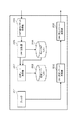
図1は本発明の実施形態の構成を表している。送信端末1−1、1−2はシェーパ11を経由してデータパケットのマルチキャスト送信を行う装置であり、受信端末2−1〜2−n2と、受信端末3−1〜3−n3と、受信端末4−1〜4−n4とはシェーパ12とシェーパ13とシェーパ14とを経由してデータパケットの受信を行う装置である。
(First embodiment)
FIG. 1 shows a configuration of an embodiment of the present invention. The transmission terminals 1-1 and 1-2 are apparatuses that perform multicast transmission of data packets via the
図2は送信側シェーパであるシェーパ11のブロック図を表し、図3は受信側シェーパであるシェーパ12とシェーパ13とシェーパ14のブロック図を表している。
FIG. 2 is a block diagram of the shaper 11 that is a transmission-side shaper, and FIG. 3 is a block diagram of the
シェーパ11はRTTの測定を行うが、その中で最短のRTTを表すBaseRTTを受信側シェーパ毎の値としてBaseRTTリスト106に保持し、優先度毎に決定されるデータ送信レートを表すrateを送信レートリスト108に保持し、RTTの測定間隔時間を表すintervalと、パケットの最大転送単位を表すMTU(Maximum Transmission Unit:最大転送単位)と、データの送信レートの増減に関わる閾値alphaを記憶領域に格納する。
The shaper 11 measures the RTT, and holds the BaseRTT representing the shortest RTT in the
また、シェーパ11はデータパケットのTOSフィールド中の優先度毎にパケットをキューに格納し、送信レートリスト108で保持しているデータ送信レートに則って、キューから順次パケットを読み込んで送信を行う。
Further, the shaper 11 stores the packet in the queue for each priority in the TOS field of the data packet, and sequentially reads and transmits the packet from the queue according to the data transmission rate held in the
また、intervalの値とrateの初期値とalphaの値とMTUの値とはユーザがあらかじめ設定しておく。 Also, the interval value, the initial rate value, the alpha value, and the MTU value are set in advance by the user.
図1において、送信端末1−1が受信端末2−1〜2−n2と受信端末3−1〜3−n3と受信端末4−1〜4−n4とにパケットをマルチキャスト送信すると、シェーパ11は送信端末1−1から送信されるパケットを取り込み、キューに格納し、送信レートリスト108に保持してあるデータ送信レートでパケットを送信しつつ、RTT測定を開始し、以後、測定間隔時間であるintervalの時間経過毎にRTT測定を行う。
In FIG. 1, when the transmitting terminal 1-1 multicasts a packet to the receiving terminals 2-1 to 2-n2, the receiving terminals 3-1 to 3-n3, and the receiving terminals 4-1 to 4-n4, the
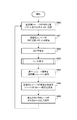
図4、図5はRTTを測定して適切なデータ送信レートを設定する処理の流れを示している。以下、図4の処理について説明する。まず、シェーパ11はクロック101から時刻情報を得て、送信時刻を記録したUDPパケット(以後、RTT測定パケットと呼ぶ)をRTT測定パケット生成部102にて生成し、RTT測定パケット送信部103からシェーパ12とシェーパ13とシェーパ14とにマルチキャスト送信する(ステップS40)。
4 and 5 show the flow of processing for measuring the RTT and setting an appropriate data transmission rate. Hereinafter, the process of FIG. 4 will be described. First, the
シェーパ12とシェーパ13とシェーパ14とはRTT測定パケット受信部109にてRTT測定パケットを受信する(ステップS41)。シェーパ12とシェーパ13とシェーパ14とは受信したRTTパケットに記録されている送信時刻を記録したUDPパケット(以後、応答パケットと呼ぶ)を応答パケット生成部110にて生成し、応答パケット送信部111からシェーパ11にユニキャスト送信する(ステップS42)。
The
シェーパ11はシェーパ12とシェーパ13とシェーパ14とからの応答パケットを応答パケット受信部104にて受信する(ステップS43)。シェーパ11はRTT演算部105にて、最も遅くに受信した応答パケットに記録されている送信時刻とクロック101から得た応答パケットの受信時刻との差分からRTTを算出し(ステップS44)、送信レート演算部107にてレート算出を行う(ステップS45)。算出した送信レートをrateに設定し、送信レートリスト108に格納する(ステップS46)。次回以降のデータ送信においては、ここまでの処理で得られたrateを適用する。
The
以下、図5を用いて図4のステップS45のレート算出処理について詳細を説明する。 Hereinafter, the rate calculation process in step S45 in FIG. 4 will be described in detail with reference to FIG.
シェーパ11はBaseRTTリスト106で保持している該当シェーパに対応するBaseRTTと算出したRTTとを比較し(ステップS50)、算出したRTTがBaseRTTより短い時間の場合には、BaseRTTに算出したRTTを設定し、BaseRTTリスト106に格納する(ステップS51)。ここで、BaseRTTの方がRTTより短い時間である場合にはBaseRTTの更新は行わない。
The
次に、シェーパ11はRTTとBaseRTTとrateとから、ネットワークに輻輳が起きていない場合に期待されるデータ送信レートであるExpectedと実際のデータ送信レートであるActualとを算出し、ExpectedとActualとの差分にBaseRTTを乗算し、期待されるデータ送信と実際のデータ送信とのレート差分にあたるDeltaを算出し(ステップS52)、Deltaとalphaとを比較する(ステップS53)。
Next, the
Deltaがalphaより小さい場合には、データ送信レートを増やしてもよいと判断し、最大転送単位MTUの大きさのパケット1つを送信した場合のレート分、すなわち、MTUをRTTで除算した値をrateに加算し、送信レートリスト108に格納する(ステップS54)。逆に、ネットワークが混雑してくると、RTTが増加するため、これに伴いDeltaはalphaより大きくなり、データ送信レートを減らす必要があると判断し、最大転送単位MTUの大きさのパケット1つを送信した場合のレート分、すなわち、MTUをRTTで除算した値をrateから減算し(ステップS55)、パケットの流量を減らすため、ネットワークの輻輳を回避することができる。 When Delta is smaller than alpha, it is determined that the data transmission rate may be increased, and the amount corresponding to the rate when one packet having the maximum transfer unit MTU size is transmitted, that is, the value obtained by dividing MTU by RTT is calculated. It is added to the rate and stored in the transmission rate list 108 (step S54). Conversely, when the network is congested, the RTT increases, and accordingly, Delta becomes larger than alpha, and it is determined that the data transmission rate needs to be reduced, and one packet having the size of the maximum transfer unit MTU is determined. Since the rate is equal to the rate of transmission, that is, the value obtained by dividing the MTU by RTT is subtracted from the rate (step S55), the packet flow rate is reduced, so that network congestion can be avoided.
また、シェーパ11は優先度毎に分けたキュー毎にrateとalphaとの値を設定して、rateを算出することにより、rateに差をつけて、優先度別の制御を行うことができる。alphaの値を大きくするほどrateは大きくなり易いため、alphaの値を大きく設定したキューに優先度の高いパケットを格納してalphaの値を小さく設定したキューに優先度の低いパケットを格納することにより、QoS制御を行うことができる。
Further, the
また、シェーパ11に送信端末1−1と送信端末1−2と複数の送信端末が接続され、送信端末1−1と送信端末1−2とが同じ優先度でマルチキャスト送信を行う場合には、送信端末1−1から送信されるパケットと送信端末1−2から送信されるパケットをシェーパ11の同じキューに格納し、同じrateを用いて送信制御を行うことにより、送信端末1−1と送信端末1−2との公平性を実現することができる。
When the transmission terminal 1-1, the transmission terminal 1-2, and a plurality of transmission terminals are connected to the
また、まずは、シェーパ11がRTT測定パケットをシェーパ12とシェーパ13とシェーパ14とにマルチキャスト送信し、シェーパ12とシェーパ13とシェーパ14とが応答パケットを送信し、シェーパ11はそれぞれのシェーパからの応答パケットを受信するが、例えば、シェーパ12からの応答パケットを最も遅く受信した場合には、シェーパ12を測定対象シェーパに設定し、次回から予め設定しておいた回数であるN回は測定対象シェーパであるシェーパ12だけにRTT測定パケットをユニキャスト送信して、RTTを算出し、レート算出を行い、N回の測定後は、再びシェーパ12とシェーパ13とシェーパ14とにRTT測定パケットをマルチキャスト送信し、測定対象シェーパを新たに設定するということを繰り返す方法もある。この方法により、測定対象シェーパのみにRTT測定パケットを送信すればよいので、ネットワーク上に流れるパケット量を減らすことができる。
First, the
また、シェーパ11は予めRTT最大許容値を設定しておき、RTT測定パケットを送信してから、RTT最大許容値の時間を過ぎても、応答パケットの返信がないシェーパがあった場合には、そのシェーパへの経路のネットワークに何らかの問題が発生していると判断し、ネットワークに問題のないシェーパへの送信に影響することを防ぐため、応答パケットの返信がないシェーパへのマルチキャスト送信を中止する方法もある。 In addition, when the shaper 11 sets an RTT maximum permissible value in advance and transmits a RTT measurement packet and there is a shaper that does not return a response packet even after the RTT maximum permissible time has elapsed, Determines that a problem has occurred in the network of the route to the shaper, and cancels multicast transmission to a shaper that does not return a response packet in order to prevent transmission to a shaper that does not have a problem with the network. There is also a method.
また、シェーパ11はRTT測定の際に、RTT測定パケットを用いず、送信端末1−1が送信するデータパケットにシェーパ11での送信時刻を記録し、シェーパ12とシェーパ13とシェーパ14とは、このデータパケットを受信し、記録されている送信時刻を記録した応答パケットをシェーパ11に送信する方法もある。この方法により、データパケットを用いてRTTを測定することで、ネットワークの流量を増やさずにRTT測定を行うことができる。
Further, the
(第二の実施の形態)
図1は本発明の実施形態の構成を表している。送信端末1−1、1−2はシェーパ11を経由してデータパケットのマルチキャスト送信を行う装置であり、受信端末2−1〜2−n2と、受信端末3−1〜3−n3と、受信端末4−1〜4−n4とはシェーパ12とシェーパ13とシェーパ14とを経由してデータパケットの受信を行う装置である。
(Second embodiment)
FIG. 1 shows a configuration of an embodiment of the present invention. The transmission terminals 1-1 and 1-2 are apparatuses that perform multicast transmission of data packets via the
図6は送信側シェーパであるシェーパ11のブロック図を表し、図7は受信側シェーパであるシェーパ12とシェーパ13とシェーパ14のブロック図を表している。
FIG. 6 shows a block diagram of the shaper 11 which is a transmission side shaper, and FIG. 7 shows a block diagram of the
シェーパ11はOWTの測定を行うが、その中で最短のOWTを表すBaseOWTを受信側シェーパ毎の値としてBaseOWTリスト206に保持し、優先度毎に決定されるデータ送信レートを表すrateを送信レートリスト208に保持し、OWTの測定間隔時間を表すintervalと、パケットの最大転送単位を表すMTU(Maximum Transmission Unit:最大転送単位)と、データの送信レートの増減に関わる閾値alphaを記憶領域に格納する。
The
また、シェーパ11はデータパケットのTOSフィールド中の優先度毎にパケットをキューに格納し、送信レートリスト208で保持しているデータ送信レートに則って、キューから順次パケットを読み込んで送信を行う。
Further, the shaper 11 stores the packet in the queue for each priority in the TOS field of the data packet, and sequentially reads and transmits the packet from the queue according to the data transmission rate held in the
また、intervalの値とrateの初期値とalphaの値とMTUの値とはユーザが予め設定しておく。図1において、送信端末1−1が受信端末2−1〜2−n2と受信端末3−1〜3−n3と受信端末4−1〜4−n4とにパケットをマルチキャスト送信すると、シェーパ11は送信端末1−1から送信されるパケットを取り込み、キューに格納し、送信レートリスト208に保持してあるデータ送信レートでパケットを送信しつつ、OWT測定を開始し、以後、測定間隔時間であるintervalの時間経過毎にOWT測定を行う。
The interval value, the initial rate value, the alpha value, and the MTU value are set in advance by the user. In FIG. 1, when the transmitting terminal 1-1 multicasts a packet to the receiving terminals 2-1 to 2-n2, the receiving terminals 3-1 to 3-n3, and the receiving terminals 4-1 to 4-n4, the
図8、図9はOWTを測定して適切なデータ送信レートを設定する処理の流れを示している。以下、図8の処理について説明する。まず、シェーパ11はクロック201から時刻情報を得て、送信時刻を記録したUDPパケット(以後、OWT測定パケットと呼ぶ)をOWT測定パケット生成部202にて生成し、OWT測定パケット送信部203からシェーパ12とシェーパ13とシェーパ14とにマルチキャスト送信する(ステップS60)。シェーパ12とシェーパ13とシェーパ14とはOWT測定パケット受信部209にてOWT測定パケットを受信する(ステップS61)。シェーパ12とシェーパ13とシェーパ14とはクロック211から得たOWT測定パケットの受信時刻とOWT測定パケットに記録されている送信時刻からOWT演算部210にてOWTを算出する(ステップS62)。
8 and 9 show the flow of processing for measuring an OWT and setting an appropriate data transmission rate. Hereinafter, the process of FIG. 8 will be described. First, the
シェーパ12とシェーパ13とシェーパ14とは算出したOWTを記録したUDPパケット(以後、OWT通知パケットと呼ぶ)をOWT通知パケット生成部212にて生成し、OWT通知パケット送信部213からシェーパ11にユニキャスト送信する(ステップS63)。シェーパ11はシェーパ12とシェーパ13とシェーパ14とからのOWT通知パケットをOWT通知パケット受信部204にて受信する(ステップS64)。シェーパ11はOWT比較部205にて、受信したOWT通知パケットに記録されているOWTの中で最も大きな値を代表OWTに設定し(ステップS65)、代表OWTを用いて送信レート演算部207にてレート算出を行う(ステップS66)。算出したレートの値をrateに設定し、送信レートリスト208に格納する(ステップS67)。次回以降のデータ送信においては、ここまでの処理で得られたrateを適用する。
The
以下、図9を用いて図8のステップS66のレート算出処理について詳細を説明する。 Hereinafter, the rate calculation process in step S66 of FIG. 8 will be described in detail with reference to FIG.
シェーパ11はBaseOWTリスト206で保持している該当シェーパに対応するBaseOWTと代表OWTとを比較し(ステップS70)、代表OWTがBaseOWTより短い時間の場合に、BaseOWTに代表OWTを設定し、BaseOWTリスト206に格納する(ステップS71)。ここで、BaseOWTの方が代表OWTより短い時間である場合にはBaseOWTの更新は行わない。
The
次に、シェーパは代表OWTとBaseOWTとrateとから、ネットワークに輻輳が起きていない場合に期待されるデータ送信レートであるExpectedと実際のデータ送信レートであるActualとを算出し、ExpectedとActualとの差分にBaseOWTを乗算し、期待されるデータ送信と実際のデータ送信とのレート差分にあたるDeltaを算出し(ステップS72)、Deltaとalphaとを比較する(ステップS73)。 Next, the shaper calculates Expected and Actual from the representative OWT, BaseOWT, and rate, and Expected, which is the expected data transmission rate when the network is not congested, and Actual, which is the actual data transmission rate. Delta is multiplied by BaseOWT, Delta corresponding to the rate difference between expected data transmission and actual data transmission is calculated (step S72), and Delta and alpha are compared (step S73).
Deltaがalphaより小さい場合には、データ送信レートを増やしてもよいと判断し、最大転送単位MTUの大きさのパケット1つを送信した場合のレート分、すなわち、MTUをOWTで除算した値をrateに加算し、送信レートリスト208に格納する(ステップS74)。逆に、ネットワークが混雑してくると、OWTが増加するため、これに伴いDeltaはalphaより大きくなり、データ送信レートを減らす必要があると判断し、最大転送単位MTUの大きさのパケット1つを送信した場合のレート分、すなわち、MTUをOWTで除算した値をrateから減算し(ステップS75)、パケットの流量を減らすため、ネットワークの輻輳を回避することができる。 When Delta is smaller than alpha, it is determined that the data transmission rate may be increased, and a value corresponding to the rate when one packet having the maximum transfer unit MTU size is transmitted, that is, a value obtained by dividing MTU by OWT is calculated. It is added to the rate and stored in the transmission rate list 208 (step S74). On the other hand, when the network is congested, OWT increases. Accordingly, Delta becomes larger than alpha, and it is determined that the data transmission rate needs to be reduced, and one packet having the size of the maximum transfer unit MTU is determined. The rate corresponding to the transmission rate, that is, the value obtained by dividing the MTU by OWT is subtracted from the rate (step S75), and the packet flow rate is reduced, so that network congestion can be avoided.
また、シェーパ11は優先度毎に分けたキュー毎にrateとalphaとの値を設定して、rateを算出することにより、rateに差をつけて、優先度別の制御を行うことができる。alphaの値を大きくするほどrateは大きくなり易いため、alphaの値を大きく設定したキューに優先度の高いパケットを格納して、alphaの値を小さく設定したキューに優先度の低いパケットを格納することにより、QoS制御を行うことができる。
Further, the
また、シェーパ11に送信端末1−1と送信端末1−2と複数の送信端末が接続され、送信端末1−1と送信端末1−2とが同じ優先度でマルチキャスト送信を行う場合には、送信端末1−1から送信されるパケットと送信端末1−2から送信されるパケットをシェーパ11の同じキューに格納し、同じrateを用いて送信制御を行うことにより、送信端末1−1と送信端末1−2との公平性を実現することができる。
When the transmission terminal 1-1, the transmission terminal 1-2, and a plurality of transmission terminals are connected to the
また、まずは、シェーパ11がOWT測定パケットをシェーパ12とシェーパ13とシェーパ14とにマルチキャスト送信し、シェーパ12とシェーパ13とシェーパ14とがOWTを算出し、OWT通知パケットを送信し、シェーパ11はシェーパ12とシェーパ13とシェーパ14とから通知されたOWTを比較するが、例えば、シェーパ12から通知されたOWTが最も大きい値だった場合には、シェーパ12を測定対象シェーパに設定し、次回から予め設定しておいた回数であるN回は測定対象シェーパであるシェーパ12だけにOWT測定パケットをユニキャスト送信してレート算出を行う。N回の測定後は、再びシェーパ12とシェーパ13とシェーパ14とにOWT測定パケットをマルチキャスト送信し、測定対象シェーパを新たに設定するということを繰り返す方法もある。この方法により、測定対象シェーパのみにOWT測定パケットを送信すればよいので、ネットワーク上に流れるパケット量を減らすことができる。
First, the
また、シェーパ11は予めOWT最大許容値を設定しておき、シェーパ12とシェーパ13とシェーパ14とから通知されるOWTを比較するときに、OWT最大許容値より通知されたOWTが大きい場合には、そのOWTを通知したシェーパへの経路のネットワークに何らかの問題が発生していると判断し、ネットワークに問題のないシェーパへの送信に影響することを防ぐため、OWT最大許容値より大きいOWTを通知したシェーパへのマルチキャスト送信を中止する方法もある。
In addition, when the shaper 11 sets an OWT maximum allowable value in advance and compares OWTs notified from the
また、シェーパ11はOWT測定の際に、OWT測定パケットを用いず、送信端末1−1が送信するデータパケットにシェーパ11での送信時刻を記録し、シェーパ12とシェーパ13とシェーパ14とはこのデータパケットを受信し、記録されている送信時刻と、データパケットの受信時刻との差分からOWTを算出する方法もある。この方法により、データパケットを用いてOWTを測定することで、ネットワーク流量を増やさずにOWT測定を行うことができる。
Also, the
(第三の実施の形態)
図1は本発明の実施形態の構成を表している。送信端末1−1、1−2はシェーパ11を経由してデータパケットのマルチキャスト送信を行う装置であり、受信端末2−1〜2−n2と、受信端末3−1〜3−n3と、受信端末4−1〜4−n4とはシェーパ12とシェーパ13とシェーパ14とを経由してデータパケットの受信を行う装置である。
(Third embodiment)
FIG. 1 shows a configuration of an embodiment of the present invention. The transmission terminals 1-1 and 1-2 are apparatuses that perform multicast transmission of data packets via the
図10は送信側シェーパであるシェーパ11のブロック図を表し、図11は受信側シェーパであるシェーパ12とシェーパ13とシェーパ14のブロック図を表している。
FIG. 10 is a block diagram of the shaper 11 that is a transmission-side shaper, and FIG. 11 is a block diagram of the
シェーパ11は優先度毎に決定されるデータ送信レートを表すrateを送信レートリスト306に保持し、OWTの測定間隔時間を表すintervalを記憶領域に格納する。シェーパ12とシェーパ13とシェーパ14とはそれぞれ、データの片方向遅延時間を表すOWTの中で最短のOWTを表すBaseOWTを送信側シェーパ毎の値としてBaseOWTリスト310に保持し、パケットの最大転送単位を表すMTUと、データの送信レートの増減に関わる閾値alphaを記憶領域に格納する。
The
また、シェーパ11はデータパケットのTOSフィールド中の優先度毎にパケットをキューに格納し、送信レートリスト306で保持しているデータ送信レートに則って、キューから順次パケットを読み込んで送信を行う。
Further, the shaper 11 stores the packet in the queue for each priority in the TOS field of the data packet, and sequentially reads and transmits the packet from the queue according to the data transmission rate held in the
また、intervalの値とrateの初期値とalphaの値とMTUの値とはユーザが予め設定しておく。図1において、送信端末1−1が受信端末2−1〜2−n2と受信端末3−1〜3−n3と受信端末4−1〜4−n4とにパケットをマルチキャスト送信すると、シェーパ11は送信端末1−1から送信されるパケットを取り込み、キューに格納し、送信レートリスト306に保持してあるデータ送信レートでパケットを送信しつつ、OWT測定を開始し、以後、測定間隔時間であるintervalの時間経過毎にOWTの測定を行う。
The interval value, the initial rate value, the alpha value, and the MTU value are set in advance by the user. In FIG. 1, when the transmitting terminal 1-1 multicasts a packet to the receiving terminals 2-1 to 2-n2, the receiving terminals 3-1 to 3-n3, and the receiving terminals 4-1 to 4-n4, the
図12、図9はOWTを測定して適切なデータ送信レートを設定する処理の流れを示している。以下、図12の処理について説明する。まず、シェーパ11はクロック301から時刻情報を得て、送信時刻と送信レートリスト306から得た現在のデータ送信レートを記録したUDPパケット(以後、OWT測定パケットと呼ぶ)をOWT測定パケット生成部302にて生成し、OWT測定パケット送信部303からシェーパ12とシェーパ13とシェーパ14とにマルチキャスト送信する(ステップS80)。
FIGS. 12 and 9 show the flow of processing for measuring an OWT and setting an appropriate data transmission rate. Hereinafter, the process of FIG. 12 will be described. First, the
シェーパ12とシェーパ13とシェーパ14とはOWT測定パケット受信部307にてOWT測定パケットを受信する(ステップS81)。シェーパ12とシェーパ13とシェーパ14とはクロック309から得たOWT測定パケットの受信時刻とOWT測定パケットに記録されている送信時刻からOWT演算部308にてOWTを算出し(ステップS82)、レート算出部311にてレート算出を行う(ステップS83)。
The
シェーパ12とシェーパ13とシェーパ14とは算出したレート結果を記録したUDPパケット(以後、レート通知パケットと呼ぶ)をレート通知パケット生成部312にて生成し、レート通知パケット送信部313からシェーパ11へユニキャスト送信する(ステップS84)。シェーパ11はシェーパ12とシェーパ13とシェーパ14とからのレート通知パケットをレート通知パケット受信部304にて受信する(ステップS85)。シェーパ11はレート比較部305にて、受信したレート通知パケットに記録されているレートの中で最も小さい値をrateに設定し、送信レートリスト306に格納する(ステップS86)。次回以降のデータ送信においては、ここまでの処理で得られたrateを適用する。
The
以下、図9を用いて図12のステップS83のレート算出処理について詳細を説明する。 Hereinafter, the rate calculation process in step S83 in FIG. 12 will be described in detail with reference to FIG.
シェーパ12とシェーパ13とシェーパ14とはBaseOWTリスト310で保持している該当シェーパに対応するBaseOWTと算出したOWTとを比較し(ステップS70)、OWTがBaseOWTより短い時間の場合には、BaseOWTにOWTを設定し、BaseOWTリスト310に格納する(ステップS71)。ここで、BaseOWTの方がOWTより短い時間である場合にはBaseOWTの更新は行わない。
The
次に、シェーパはOWTとBaseOWTとOWT測定パケットに記録されているデータ送信レートrateとから、ネットワークに輻輳が起きていない場合に期待されるデータ送信レートであるExpectedと実際のデータ送信レートであるActualとを算出し、ExpectedとActualとの差分にBaseOWTを乗算し、期待されるデータ送信と実際のデータ送信とのレート差分にあたるDeltaを算出し(ステップS72)、Deltaとalphaとを比較する(ステップS73)。 Next, from the data transmission rate rate recorded in the OWT, BaseOWT, and OWT measurement packet, the shaper is Expected, which is a data transmission rate expected when the network is not congested, and the actual data transmission rate. Actual is calculated, the difference between Expected and Actual is multiplied by BaseOWT, Delta corresponding to the rate difference between expected data transmission and actual data transmission is calculated (step S72), and Delta is compared with alpha ( Step S73).
Deltaがalphaより小さい場合には、データ送信レートを増やしてもよいと判断し、最大転送単位MTUの大きさのパケット1つを送信した場合のレート分、すなわち、MTUをOWTで除算した値をrateに加算する(ステップS74)。逆に、ネットワークが混雑してくると、OWTが増加するため、これに伴いDeltaはalphaより大きくなり、データ送信レートを減らす必要があると判断し、最大転送単位MTUの大きさのパケット1つを送信した場合のレート分、すなわち、MTUをOWTで除算した値をrateから減算し(ステップS75)、パケットの流量を減らすため、ネットワークの輻輳を回避することができる。 When Delta is smaller than alpha, it is determined that the data transmission rate may be increased, and a value corresponding to the rate when one packet having the maximum transfer unit MTU size is transmitted, that is, a value obtained by dividing MTU by OWT is calculated. Add to rate (step S74). On the other hand, when the network is congested, OWT increases. Accordingly, Delta becomes larger than alpha, and it is determined that the data transmission rate needs to be reduced, and one packet having the size of the maximum transfer unit MTU is determined. The rate corresponding to the transmission rate, that is, the value obtained by dividing the MTU by OWT is subtracted from the rate (step S75), and the packet flow rate is reduced, so that network congestion can be avoided.
また、シェーパ12とシェーパ13とシェーパ14とは優先度毎にalphaの値を設定して、rateを算出することにより、rateに差をつけて、優先度別の制御を行うことができる。alphaの値を大きくするほどrateは大きくなりやすいため、alphaの値を大きく設定したキューに優先度の高いパケットを格納して、alphaの値を小さく設定したキューに優先度の低いパケットを格納することにより、QoS制御をすることができる。
In addition, the
また、シェーパ11に送信端末1−1と送信端末1−2と複数の送信端末が接続され、送信端末1−1と送信端末1−2とが同じ優先度でマルチキャスト送信を行う場合には、送信端末1−1から送信されるパケットと送信端末1−2から送信されるパケットとをシェーパ11の同じキューに格納し、同じrateを用いて送信制御を行うことにより、送信端末1−1と送信端末1−2との公平性を実現することができる。
When the transmission terminal 1-1, the transmission terminal 1-2, and a plurality of transmission terminals are connected to the
また、まずは、シェーパ11からOWT測定パケットをシェーパ12とシェーパ13とシェーパ14とにマルチキャスト送信し、シェーパ11はシェーパ12とシェーパ13とシェーパ14とから通知されたレートを比較するが、例えば、シェーパ12から通知されたレートが最も小さい値だった場合には、シェーパ12を測定対象シェーパに設定し、次回から予め設定しておいた回数であるN回は測定対象シェーパであるシェーパ12だけにOWT測定パケットをユニキャスト送信してレート算出を行う。N回の測定後は、再びシェーパ12とシェーパ13とシェーパ14とにOWT測定パケットをマルチキャスト送信し、測定対象シェーパを新たに設定するということを繰り返す方法もある。この方法により、測定対象シェーパのみにOWT測定パケットを送信すればよいので、ネットワーク上に流れるパケット量を減らすことができる。
First, the OWT measurement packet is multicast-transmitted from the shaper 11 to the
また、シェーパ11は予めデータ送信レート最小許容値を設定しておき、シェーパ12とシェーパ13とシェーパ14とから通知されるレートを比較するときに、データ送信レート最小許容値より通知されたデータ送信レートが小さい場合には、そのレートを通知したシェーパへの経路のネットワークに何らかの問題が発生していると判断し、ネットワークに問題のないシェーパへの送信に影響することを防ぐため、データ送信レート最小許容値より小さいデータ送信レートを通知したシェーパへのマルチキャスト送信を中止する方法もある。
Further, the
また、シェーパ11はOWT測定の際に、OWT測定パケットを用いず、送信端末1−1が送信するデータパケットにシェーパ11での送信時刻を記録し、シェーパ12とシェーパ13とシェーパ14とはこのデータパケットを受信し、記録されている送信時刻と、データパケットの受信時刻との差分からOWTを算出する方法もある。この方法により、データパケットを用いてOWTを測定することで、ネットワークの流量を増やさずにOWT測定を行うことができる。
Also, the
(第四の実施の形態)
第四の実施の形態は、汎用の情報処理装置にインストールすることにより、その情報処理装置にシェーパ11〜14に相応する機能を実現させるプログラムである。このプログラムは、記録媒体に記録されて情報処理装置にインストールされ、あるいは通信回線を介して情報処理装置にインストールされることにより当該情報処理装置に、シェーパ11〜14にそれぞれ相応する機能を実現させることができる。
(Fourth embodiment)
The fourth embodiment is a program that, when installed in a general-purpose information processing apparatus, causes the information processing apparatus to realize functions corresponding to the
本発明によれば、シェーパがRTTもしくはOWTを測定し、それを用いてTCP Vegasと同等のフロー制御を行うことにより、ネットワークを有効に利用し、複数マルチキャスト通信間の公平性を保ち、ネットワークの輻輳を防ぐマルチキャスト通信を実現することが可能となる。 According to the present invention, the shaper measures RTT or OWT and uses it to perform flow control equivalent to TCP Vegas, thereby effectively using the network and maintaining fairness among multiple multicast communications. It is possible to realize multicast communication that prevents congestion.
1−1、1−2 送信端末
2−1〜2−n2、3−1〜3−n3、4−1〜4−n4 受信端末
11〜14 シェーパ
101、201、211、301、309 クロック
102 RRT測定パケット生成部
103 RTT測定パケット送信部
104 応答パケット受信部
105 RRT演算部
106 BaseRTTリスト
107、207 送信レート演算部
108、208、306 送信レートリスト
109 RTT測定パケット受信部
110 応答パケット生成部
111 応答パケット送信部
202、302 OWT測定パケット生成部
203、303 OWT測定パケット送信部
204 OWT通知パケット受信部
205 OWT比較部
206、310 BaseOUTリスト
209、307 OWT測定パケット受信部
210、308 OWT演算部
212 OWT通知パケット生成部
213 OWT通知パケット送信部
304 レート通知パケット受信部
305 レート比較部
311 レート演算部
312 レート通知パケット生成部
313 レート通知パケット送信部
1-1, 1-2 Transmission terminals 2-1 to 2-n2, 3-1 to 3-n3, 4-1 to 4-
Claims (16)
送信端末に接続されているシェーパは、予め設定された時間間隔毎に送信時刻を記録したRTT(Round Trip Time)測定パケットを受信端末に接続されている複数のシェーパに送信し、
受信端末に接続されているシェーパは、受信したRTT測定パケットに記録してある送信時刻を記録した応答パケットを送信端末に接続されているシェーパに送信し、
送信端末に接続されているシェーパは、
複数の応答パケットを受信し、その中で最も遅く受信した応答パケットの受信時刻と当該応答パケットに記録してある送信時刻との差分からデータ往復遅延時間を算出し、
このデータ往復遅延時間が自シェーパで保持している最短データ往復遅延時間よりも短い場合には、当該データ往復遅延時間を新しい最短データ往復遅延時間として保持し、
前記データ往復遅延時間を最短データ往復遅延時間で除算したものにデータの優先度毎に設定されるデータ送信レートを乗算して期待されるデータ送信レートを得て、
期待されるデータ送信レートから現在のデータ送信レートを減算してレート差分を得て、
レート差分が優先度毎の所定の閾値よりも小さい場合にはデータ送信レートを増やし、
レート差分が優先度毎の所定の閾値よりも大きい場合にはデータ送信レートを減らし、
当該データ送信レートの増減により求めたデータ送信レートを最適データ送信レートとして採用する
ことを特徴とするフロー制御方法。 In a flow control method applied to multicast communication in which a transmitting terminal and a plurality of receiving terminals perform data transmission / reception via a shaper connected to each terminal device,
The shaper connected to the transmitting terminal transmits an RTT (Round Trip Time) measurement packet in which the transmission time is recorded every preset time interval to a plurality of shapers connected to the receiving terminal,
The shaper connected to the receiving terminal transmits a response packet recording the transmission time recorded in the received RTT measurement packet to the shaper connected to the transmitting terminal,
The shaper connected to the sending terminal
Receive a plurality of response packets, calculate the data round-trip delay time from the difference between the reception time of the response packet received the latest and the transmission time recorded in the response packet,
When this data round trip delay time is shorter than the shortest data round trip delay time held by the own shaper, the data round trip delay time is held as a new shortest data round trip delay time,
Multiplying the data round-trip delay time by the shortest data round-trip delay time multiplied by the data transmission rate set for each data priority to obtain the expected data transmission rate,
Subtract the current data transmission rate from the expected data transmission rate to get the rate difference,
If the rate difference is smaller than the predetermined threshold for each priority, increase the data transmission rate,
If the rate difference is greater than a predetermined threshold for each priority, reduce the data transmission rate,
A flow control method characterized in that a data transmission rate obtained by increasing or decreasing the data transmission rate is adopted as an optimum data transmission rate.
送信端末に接続されているシェーパは、送信時刻を記録したRTT測定パケットを受信端末に接続されている複数のシェーパに送信し、
受信端末に接続されているシェーパは、受信したRTT測定パケットに記録してある送信時刻を記録した応答パケットを送信端末に接続されているシェーパに送信し、
送信端末に接続されているシェーパは、
複数の応答パケットを受信し、その中で最も遅く受信した応答パケットの送信元のシェーパを測定対象シェーパとし、
予め設定された時間間隔毎に、予め設定された回数だけ、当該測定対象シェーパに対し送信時刻を記録したRTT測定パケットを送信し、
このRTT測定パケットを受信した測定対象シェーパは、RTT測定パケットに記録されている送信時刻を記録した応答パケットを前記送信端末に接続されているシェーパに送信し、
送信端末に接続されているシェーパは、
この応答パケットに基づきデータ往復遅延時間を算出して前記最適データ送信レートを算出することを前記予め設定された回数繰り返し、
前記予め設定された回数のRTT測定パケットの送信後は、再び、受信端末に接続されている複数のシェーパに送信時刻を記録したRTT測定パケットを送信し、新たな測定対象シェーパを決定する
という処理を繰り返す請求項1記載のフロー制御方法。 Instead of transmitting the RTT measurement packet in which the shaper connected to the transmission terminal records the transmission time at preset time intervals to the plurality of shapers connected to the reception terminal,
The shaper connected to the transmission terminal transmits an RTT measurement packet recording the transmission time to a plurality of shapers connected to the reception terminal,
The shaper connected to the receiving terminal transmits a response packet recording the transmission time recorded in the received RTT measurement packet to the shaper connected to the transmitting terminal,
The shaper connected to the sending terminal
Multiple response packets are received, and the shaper that is the source of the response packet that has been received the latest is the shaper to be measured,
For each preset time interval, send the RTT measurement packet recording the transmission time to the measurement target shaper for a preset number of times,
The measurement target shaper that has received this RTT measurement packet transmits a response packet that records the transmission time recorded in the RTT measurement packet to the shaper connected to the transmission terminal,
The shaper connected to the sending terminal
Calculating the data round-trip delay time based on the response packet to calculate the optimum data transmission rate is repeated the preset number of times,
After transmitting the RTT measurement packet for the preset number of times, the RTT measurement packet in which the transmission time is recorded is transmitted again to a plurality of shapers connected to the receiving terminal, and a new measurement target shaper is determined. The flow control method according to claim 1, wherein:
受信端末に接続されているシェーパは、受信したデータパケットに記録されている送信時刻を記録した応答パケットを前記送信端末に接続されているシェーパに送信する
請求項1または2記載のフロー制御方法。 The shaper connected to the transmission terminal records the transmission time at the shaper in the data packet transmitted from the transmission terminal instead of the RTT measurement packet,
The flow control method according to claim 1, wherein the shaper connected to the receiving terminal transmits a response packet in which the transmission time recorded in the received data packet is recorded to the shaper connected to the transmitting terminal.
請求項1ないし3のいずれかに記載のフロー制御方法。 The shaper connected to the transmitting terminal transmits the RTT measurement packet or data packet in which the transmission time is recorded, and the shaper connected to the receiving terminal does not exceed the preset RTT maximum allowable value. The flow control method according to claim 1, wherein when no response packet is received, data packet transmission to the shaper is stopped.
送信端末に接続されているシェーパは、予め設定された時間間隔毎に送信時刻を記録したOWT(One Way trip Time)測定パケットを受信端末に接続されている複数のシェーパに送信し、
受信端末に接続されているシェーパは、受信したOWT測定パケットに記録してある送信時刻と当該OWT測定パケットの受信時刻との差分からデータ片方向遅延時間を算出し、データ片方向遅延時間を記録したOWT通知パケットを送信端末に接続されているシェーパに送信し、
送信端末に接続されているシェーパは、
受信した複数のOWT通知パケットに記録してあるデータ片方向遅延時間を比較し、その中で最大の値を代表データ片方向遅延時間とし、
代表データ片方向遅延時間が自シェーパで保持している最短データ片方向遅延時間よりも短い場合には、当該代表データ片方向遅延時間を新しい最短データ片方向遅延時間として保持し、
代表データ片方向遅延時間を最短データ片方向遅延時間で除算したものにデータの優先度毎に設定されるデータ送信レートを乗算して期待されるデータ送信レートを得て、
期待されるデータ送信レートから現在のデータ送信レートを減算してレート差分を得て、
レート差分が優先度毎の所定の閾値よりも小さい場合にはデータ送信レートを増やし、
レート差分が優先度毎の所定の閾値よりも大きい場合にはデータ送信レートを減らし、
当該データ送信レートの増減により求めたデータ送信レートを最適データ送信レートとして採用する
ことを特徴とするフロー制御方法。 In a flow control method applied to multicast communication in which a transmitting terminal and a plurality of receiving terminals perform data transmission / reception via a shaper connected to each terminal device,
The shaper connected to the transmitting terminal transmits an OWT (One Way trip Time) measurement packet in which the transmission time is recorded at a preset time interval to a plurality of shapers connected to the receiving terminal,
The shaper connected to the receiving terminal calculates the data one-way delay time from the difference between the transmission time recorded in the received OWT measurement packet and the reception time of the OWT measurement packet, and records the data one-way delay time. Send the OWT notification packet to the shaper connected to the sending terminal,
The shaper connected to the sending terminal
The data one-way delay times recorded in the received OWT notification packets are compared, and the maximum value among them is set as the representative data one-way delay time.
If the representative data one-way delay time is shorter than the shortest data one-way delay time held by the own shaper, the representative data one-way delay time is held as a new shortest data one-way delay time,
Obtain the expected data transmission rate by multiplying the representative data one-way delay time divided by the shortest data one-way delay time by the data transmission rate set for each data priority,
Subtract the current data transmission rate from the expected data transmission rate to get the rate difference,
If the rate difference is smaller than the predetermined threshold for each priority, increase the data transmission rate,
If the rate difference is greater than a predetermined threshold for each priority, reduce the data transmission rate,
A flow control method characterized in that a data transmission rate obtained by increasing or decreasing the data transmission rate is adopted as an optimum data transmission rate.
送信端末に接続されているシェーパは、送信時刻を記録したOWT測定パケットを受信端末に接続されている複数のシェーパに送信し、
受信端末に接続されているシェーパは、受信したOWT測定パケットに記録してある送信時刻と当該OWT測定パケットの受信時刻との差分からデータ片方向遅延時間を算出し、当該データ片方向遅延時間を記録したOWT通知パケットを前記送信端末に接続されているシェーパに送信し、
送信端末に接続されているシェーパは、
複数のOWT通知パケットを受信し、その中で最も大きなデータ片方向遅延時間が記録されたOWT通知パケットの送信元のシェーパを測定対象シェーパとし、
予め設定された時間間隔毎に、予め設定された回数だけ、当該測定対象シェーパに対し送信時刻を記録したOWT測定パケットを送信し、
このOWT測定パケットを受信した測定対象シェーパは、OWT測定パケットに記録されている送信時刻と当該OWT測定パケットの受信時刻との差分からデータ片方方向遅延時間を算出した結果を記録したOWT通知パケットを前記送信端末に接続されているシェーパに送信し、
送信端末に接続されているシェーパは、このOWT通知パケットに記録されたデータ片方向遅延時間に基づき前記最適データ送信レートを算出することを前記予め設定された回数繰り返し、
前記予め設定された回数のOWT測定パケットの送信後は、再び、受信端末に接続されている複数のシェーパに送信時刻を記録したOWT測定パケットを送信し、新たな測定対象シェーパを決定する
という処理を繰り返す請求項5記載のフロー制御方法。 Instead of transmitting the OWT measurement packet in which the shaper connected to the transmission terminal records the transmission time at preset time intervals to the plurality of shapers connected to the reception terminal,
The shaper connected to the transmitting terminal transmits an OWT measurement packet recording the transmission time to a plurality of shapers connected to the receiving terminal,
The shaper connected to the receiving terminal calculates the data one-way delay time from the difference between the transmission time recorded in the received OWT measurement packet and the reception time of the OWT measurement packet, and calculates the data one-way delay time. Send the recorded OWT notification packet to the shaper connected to the sending terminal;
The shaper connected to the sending terminal
A plurality of OWT notification packets are received, and the shaper of the transmission source of the OWT notification packet in which the largest data one-way delay time is recorded is set as a measurement target shaper.
For each preset time interval, an OWT measurement packet in which the transmission time is recorded is transmitted to the measurement target shaper a preset number of times.
The measurement target shaper that has received the OWT measurement packet receives the OWT notification packet that records the result of calculating the data one-way delay time from the difference between the transmission time recorded in the OWT measurement packet and the reception time of the OWT measurement packet. Send to the shaper connected to the sending terminal,
The shaper connected to the transmitting terminal repeatedly calculates the optimum data transmission rate based on the data one-way delay time recorded in the OWT notification packet, the preset number of times,
After transmitting the OWT measurement packet for the preset number of times, the OWT measurement packet in which the transmission time is recorded is transmitted again to a plurality of shapers connected to the receiving terminal, and a new measurement target shaper is determined. The flow control method according to claim 5, wherein:
受信端末に接続されているシェーパは、受信したデータパケットに記録されている送信時刻と当該データパケットの受信時刻との差分から算出したデータ片方向遅延時間を記録したOWT通知パケットを前記送信端末に接続されているシェーパに送信する
請求項5または6記載のフロー制御方法。 The shaper connected to the transmission terminal records the transmission time at the shaper in the data packet transmitted from the transmission terminal instead of the OWT measurement packet,
The shaper connected to the receiving terminal sends an OWT notification packet in which the data one-way delay time calculated from the difference between the transmission time recorded in the received data packet and the reception time of the data packet is recorded to the transmitting terminal. The flow control method according to claim 5, wherein the flow control method is transmitted to a connected shaper.
請求項5ないし7のいずれかに記載のフロー制御方法。 When the data one-way delay time recorded in the response packet exceeds a preset data one-way delay time maximum allowable value, the shaper connected to the transmission terminal transmits a data packet to the shaper. The flow control method according to claim 5, wherein transmission is stopped.
送信端末に接続されているシェーパは、予め設定された時間間隔毎に送信時刻を記録したOWT測定パケットを受信端末に接続されている複数のシェーパに送信し、
受信端末に接続されているシェーパは、
受信したOWT測定パケットに記録してある送信時刻と当該OWT測定パケットの受信時刻との差分からデータ片方向遅延時間を算出し、
当該データ片方向遅延時間が自シェーパで保持している最短データ片方向遅延時間よりも短い場合には、当該データ片方向遅延時間を新しい最短データ片方向遅延時間として保持し、
データ片方向遅延時間を最短データ片方向遅延時間で除算したものにデータの優先度毎に設定されるデータ送信レートを乗算して期待されるデータ送信レートを得て、
期待されるデータ送信レートから現在のデータ送信レートを減算してレート差分を得て、
レート差分が優先度毎の所定の閾値よりも小さい場合にはデータ送信レートを増やし、
レート差分が優先度毎の所定の閾値よりも大きい場合にはデータ送信レートを減らし、
当該データ送信レートの増減により求めたデータ送信レートを記録したレート通知パケットを送信端末に接続されているシェーパに送信し、
送信端末に接続されているシェーパは、受信した複数のレート通知パケットに記録されているデータ送信レートを比較し、その中で最小の値を最適データ送信レートとして採用する
ことを特徴とするフロー制御方法。 In a flow control method applied to multicast communication in which a transmitting terminal and a plurality of receiving terminals perform data transmission / reception via a shaper connected to each terminal device,
The shaper connected to the transmitting terminal transmits an OWT measurement packet in which the transmission time is recorded at a preset time interval to a plurality of shapers connected to the receiving terminal,
The shaper connected to the receiving terminal
A data one-way delay time is calculated from the difference between the transmission time recorded in the received OWT measurement packet and the reception time of the OWT measurement packet,
When the data one-way delay time is shorter than the shortest data one-way delay time held by the own shaper, the data one-way delay time is held as a new shortest data one-way delay time,
Multiply the data one-way delay time by the shortest data one-way delay time and multiply the data transmission rate set for each data priority to obtain the expected data transmission rate,
Subtract the current data transmission rate from the expected data transmission rate to get the rate difference,
If the rate difference is smaller than the predetermined threshold for each priority, increase the data transmission rate,
If the rate difference is greater than a predetermined threshold for each priority, reduce the data transmission rate,
Send a rate notification packet that records the data transmission rate obtained by increasing or decreasing the data transmission rate to the shaper connected to the transmitting terminal,
The shaper connected to the transmitting terminal compares the data transmission rates recorded in the received multiple rate notification packets, and adopts the minimum value among them as the optimum data transmission rate. Method.
送信端末に接続されているシェーパは、送信時刻を記録したOWT測定パケットを受信端末に接続されている複数のシェーパに送信し、
受信端末に接続されているシェーパは、
受信したOWT測定パケットに記録してある送信時刻と当該OWT測定パケットの受信時刻との差分からデータ片方向遅延時間を算出し、
当該データ片方向遅延時間が自シェーパで保持している最短データ片方向遅延時間よりも短い場合には、当該データ片方向遅延時間を新しい最短データ片方向遅延時間として保持し、
データ片方向遅延時間を最短データ片方向遅延時間で除算したものにデータの優先度毎に設定されるデータ送信レートを乗算して期待されるデータ送信レートを得て、
期待されるデータ送信レートから現在のデータ送信レートを減算してレート差分を得て、
レート差分が優先度毎の所定の閾値よりも小さい場合にはデータ送信レートを増やし、
レート差分が優先度毎の所定の閾値よりも大きい場合にはデータ送信レートを減らし、
当該データ送信レートの増減により求めたデータ送信レートを記録したレート通知パケットを送信端末に接続されているシェーパに送信し、
送信端末に接続されているシェーパは、
受信した複数のレート通知パケットに記録されているデータ送信レートを比較し、その中で最も小さな値のデータ送信レートを記録したレート通知パケットの送信元のシェーパを測定対象シェーパとし、
当該測定対象シェーパに、予め設定された時間間隔毎に、予め設定された回数だけ、送信時刻を記録したOWT測定パケットを送信し、
測定対象シェーパは、データ片方向遅延時間を算出し、データ送信レートを算出し、データ送信レートを記録したレート通知パケットを前記送信端末に接続されているシェーパに送信し、
送信端末に接続されているシェーパは、
受信したレート通知パケットに記録されているデータ送信レートを採用することを繰り返し、
予め設定された回数の送信後は、再び受信端末に接続されている複数のシェーパに送信時刻を記録したパケットを送信し、新たな測定対象シェーパを決定する
という処理を繰り返す
請求項9記載のフロー制御方法。 Instead of transmitting the OWT measurement packet in which the shaper connected to the transmission terminal records the transmission time at preset time intervals to the plurality of shapers connected to the reception terminal,
The shaper connected to the transmitting terminal transmits an OWT measurement packet recording the transmission time to a plurality of shapers connected to the receiving terminal,
The shaper connected to the receiving terminal
A data one-way delay time is calculated from the difference between the transmission time recorded in the received OWT measurement packet and the reception time of the OWT measurement packet,
When the data one-way delay time is shorter than the shortest data one-way delay time held by the own shaper, the data one-way delay time is held as a new shortest data one-way delay time,
Multiply the data one-way delay time by the shortest data one-way delay time and multiply the data transmission rate set for each data priority to obtain the expected data transmission rate,
Subtract the current data transmission rate from the expected data transmission rate to get the rate difference,
If the rate difference is smaller than the predetermined threshold for each priority, increase the data transmission rate,
If the rate difference is greater than a predetermined threshold for each priority, reduce the data transmission rate,
Send a rate notification packet that records the data transmission rate obtained by increasing or decreasing the data transmission rate to the shaper connected to the transmission terminal,
The shaper connected to the sending terminal
Compare the data transmission rate recorded in the received multiple rate notification packets, the shaper of the source of the rate notification packet that recorded the data transmission rate of the smallest value among them as the measurement target shaper,
The OWT measurement packet in which the transmission time is recorded is transmitted to the measurement target shaper at a preset time interval for a preset number of times.
The measurement target shaper calculates a data one-way delay time, calculates a data transmission rate, transmits a rate notification packet in which the data transmission rate is recorded to a shaper connected to the transmission terminal,
The shaper connected to the sending terminal
Repeatedly adopt the data transmission rate recorded in the received rate notification packet,
The flow according to claim 9, wherein after the preset number of transmissions, the process of transmitting a packet recording transmission times to a plurality of shapers connected to the receiving terminal again and determining a new measurement target shaper is repeated. Control method.
受信端末に接続されているシェーパは、受信したデータパケットに記録されている送信時刻と当該データパケットの受信時刻との差分からデータ片方向遅延時間を算出してデータ送信レートの算出を行い、当該データ送信レートを記録したレート通知パケットを前記送信端末に接続されているシェーパに送信する
請求項9または10記載のフロー制御方法。 The shaper connected to the transmission terminal records the transmission time at the shaper in the data packet transmitted from the transmission terminal instead of the OWT measurement packet,
The shaper connected to the receiving terminal calculates the data transmission rate by calculating the data one-way delay time from the difference between the transmission time recorded in the received data packet and the reception time of the data packet, The flow control method according to claim 9 or 10, wherein a rate notification packet in which a data transmission rate is recorded is transmitted to a shaper connected to the transmitting terminal.
請求項9ないし11のいずれかに記載のフロー制御方法。 When the data transmission rate recorded in the rate notification packet is smaller than the preset data transmission rate minimum allowable value, the shaper connected to the transmission terminal transmits data to the shaper that has notified the data transmission rate. The flow control method according to claim 9, wherein packet transmission is stopped.
Priority Applications (1)
| Application Number | Priority Date | Filing Date | Title |
|---|---|---|---|
| JP2005162798A JP4402619B2 (en) | 2005-06-02 | 2005-06-02 | Multicast communication flow control method and apparatus |
Applications Claiming Priority (1)
| Application Number | Priority Date | Filing Date | Title |
|---|---|---|---|
| JP2005162798A JP4402619B2 (en) | 2005-06-02 | 2005-06-02 | Multicast communication flow control method and apparatus |
Publications (2)
| Publication Number | Publication Date |
|---|---|
| JP2006340081A JP2006340081A (en) | 2006-12-14 |
| JP4402619B2 true JP4402619B2 (en) | 2010-01-20 |
Family
ID=37560217
Family Applications (1)
| Application Number | Title | Priority Date | Filing Date |
|---|---|---|---|
| JP2005162798A Expired - Fee Related JP4402619B2 (en) | 2005-06-02 | 2005-06-02 | Multicast communication flow control method and apparatus |
Country Status (1)
| Country | Link |
|---|---|
| JP (1) | JP4402619B2 (en) |
Cited By (1)
| Publication number | Priority date | Publication date | Assignee | Title |
|---|---|---|---|---|
| KR102011469B1 (en) * | 2019-04-25 | 2019-08-16 | 한화시스템(주) | Method and apparatus for communication status measuring in naval combat system |
Families Citing this family (9)
| Publication number | Priority date | Publication date | Assignee | Title |
|---|---|---|---|---|
| JP2006340078A (en) * | 2005-06-02 | 2006-12-14 | Nippon Telegr & Teleph Corp <Ntt> | Flow control method and apparatus thereof |
| JP4815534B2 (en) * | 2007-07-13 | 2011-11-16 | 富士通株式会社 | Packet delay characteristic measuring apparatus and method |
| JP2009159499A (en) * | 2007-12-27 | 2009-07-16 | Nec Corp | Method, system and station, for measuring delay time of echo request/response in network |
| JP6205912B2 (en) * | 2013-07-05 | 2017-10-04 | 富士通株式会社 | Information processing apparatus, distribution method, and distribution program |
| JP6004116B2 (en) | 2013-09-26 | 2016-10-05 | 富士通株式会社 | Measuring device, communication device, relay device, measuring method and measuring program |
| KR20190005833A (en) * | 2016-05-11 | 2019-01-16 | 광동 오포 모바일 텔레커뮤니케이션즈 코포레이션 리미티드 | Communication method and communication device |
| JP7251182B2 (en) * | 2019-02-06 | 2023-04-04 | 日本電気株式会社 | CONTROLLER, PROCESSING DEVICE CONTROL METHOD AND PROGRAM |
| CN112217686B (en) * | 2019-07-12 | 2022-12-27 | 华为技术有限公司 | System, method and device for evaluating round trip delay |
| CN113542129B (en) * | 2021-07-15 | 2023-01-24 | 无锡思朗电子科技有限公司 | Single transmission method using signal linked list |
-
2005
- 2005-06-02 JP JP2005162798A patent/JP4402619B2/en not_active Expired - Fee Related
Cited By (1)
| Publication number | Priority date | Publication date | Assignee | Title |
|---|---|---|---|---|
| KR102011469B1 (en) * | 2019-04-25 | 2019-08-16 | 한화시스템(주) | Method and apparatus for communication status measuring in naval combat system |
Also Published As
| Publication number | Publication date |
|---|---|
| JP2006340081A (en) | 2006-12-14 |
Similar Documents
| Publication | Publication Date | Title |
|---|---|---|
| JP4402619B2 (en) | Multicast communication flow control method and apparatus | |
| Al-Saadi et al. | A survey of delay-based and hybrid TCP congestion control algorithms | |
| JP3590044B2 (en) | Dynamic data packet transmission method using RTP and RTCP protocols | |
| US20030026207A1 (en) | Method for supporting non-linear, highly scalable increase-decrease congestion control scheme | |
| Gao et al. | A state feedback control approach to stabilizing queues for ECN-enabled TCP connections | |
| JP2006014329A (en) | Communication terminal | |
| Kanagarathinam et al. | D-TCP: Dynamic TCP congestion control algorithm for next generation mobile networks | |
| Mamatas et al. | Approaches to congestion control in packet networks | |
| US20100202469A1 (en) | Queue management system and methods | |
| CN108494699B (en) | Network congestion control method with central control node | |
| Weigle et al. | Delay-based early congestion detection and adaptation in TCP: impact on web performance | |
| CN113438180B (en) | Transmission control method, device and equipment for UDP (user Datagram protocol) data packet and readable storage medium | |
| Šošić et al. | Resolving poor TCP performance on high-speed long distance links—Overview and comparison of BIC, CUBIC and Hybla | |
| JP2004297127A (en) | Portable terminal and server | |
| Na et al. | TCP-like flow control algorithm for real-time applications | |
| JP3853784B2 (en) | Data communication management method | |
| Gosai et al. | Evolution of Congestion Control Mechanisms for TCP and Non TCP Protocols | |
| Lu et al. | EQF: An explicit queue-length feedback for TCP congestion control in datacenter networks | |
| Jaiswal et al. | A comparative performance analysis of TCP congestion control algorithm: elastic TCP vs. e-Elastic TCP | |
| Abbasov | AHRED: A robust AQM algorithm for wireless ad hoc networks | |
| Adesanmi et al. | Controlling TCP Incast congestion in data centre networks | |
| JP6897769B2 (en) | Data transmitters, methods and programs | |
| Tsao et al. | A fast-converging tcp-equivalent window-averaging rate control scheme | |
| Santhi et al. | A new approach to Active Queue Management for TCP with ECN | |
| Gholizadeh | Congestion Control in Software-Defined Networks: A Simulation Study |
Legal Events
| Date | Code | Title | Description |
|---|---|---|---|
| A621 | Written request for application examination |
Free format text: JAPANESE INTERMEDIATE CODE: A621 Effective date: 20070914 |
|
| RD01 | Notification of change of attorney |
Free format text: JAPANESE INTERMEDIATE CODE: A7426 Effective date: 20090910 |
|
| RD02 | Notification of acceptance of power of attorney |
Free format text: JAPANESE INTERMEDIATE CODE: A7422 Effective date: 20090910 |
|
| RD04 | Notification of resignation of power of attorney |
Free format text: JAPANESE INTERMEDIATE CODE: A7424 Effective date: 20090910 |
|
| A977 | Report on retrieval |
Free format text: JAPANESE INTERMEDIATE CODE: A971007 Effective date: 20091001 |
|
| TRDD | Decision of grant or rejection written | ||
| A521 | Written amendment |
Free format text: JAPANESE INTERMEDIATE CODE: A821 Effective date: 20090910 |
|
| A01 | Written decision to grant a patent or to grant a registration (utility model) |
Free format text: JAPANESE INTERMEDIATE CODE: A01 Effective date: 20091027 |
|
| A01 | Written decision to grant a patent or to grant a registration (utility model) |
Free format text: JAPANESE INTERMEDIATE CODE: A01 |
|
| A61 | First payment of annual fees (during grant procedure) |
Free format text: JAPANESE INTERMEDIATE CODE: A61 Effective date: 20091029 |
|
| R150 | Certificate of patent or registration of utility model |
Ref document number: 4402619 Country of ref document: JP Free format text: JAPANESE INTERMEDIATE CODE: R150 Free format text: JAPANESE INTERMEDIATE CODE: R150 |
|
| FPAY | Renewal fee payment (event date is renewal date of database) |
Free format text: PAYMENT UNTIL: 20121106 Year of fee payment: 3 |
|
| FPAY | Renewal fee payment (event date is renewal date of database) |
Free format text: PAYMENT UNTIL: 20121106 Year of fee payment: 3 |
|
| FPAY | Renewal fee payment (event date is renewal date of database) |
Free format text: PAYMENT UNTIL: 20131106 Year of fee payment: 4 |
|
| S531 | Written request for registration of change of domicile |
Free format text: JAPANESE INTERMEDIATE CODE: R313531 |
|
| R350 | Written notification of registration of transfer |
Free format text: JAPANESE INTERMEDIATE CODE: R350 |
|
| S531 | Written request for registration of change of domicile |
Free format text: JAPANESE INTERMEDIATE CODE: R313531 |
|
| R350 | Written notification of registration of transfer |
Free format text: JAPANESE INTERMEDIATE CODE: R350 |
|
| S111 | Request for change of ownership or part of ownership |
Free format text: JAPANESE INTERMEDIATE CODE: R313117 |
|
| R350 | Written notification of registration of transfer |
Free format text: JAPANESE INTERMEDIATE CODE: R350 |
|
| LAPS | Cancellation because of no payment of annual fees |