JP4401884B2 - Video signal processing apparatus and method - Google Patents
Video signal processing apparatus and method Download PDFInfo
- Publication number
- JP4401884B2 JP4401884B2 JP2004210592A JP2004210592A JP4401884B2 JP 4401884 B2 JP4401884 B2 JP 4401884B2 JP 2004210592 A JP2004210592 A JP 2004210592A JP 2004210592 A JP2004210592 A JP 2004210592A JP 4401884 B2 JP4401884 B2 JP 4401884B2
- Authority
- JP
- Japan
- Prior art keywords
- image information
- video signal
- character image
- video
- signal
- Prior art date
- Legal status (The legal status is an assumption and is not a legal conclusion. Google has not performed a legal analysis and makes no representation as to the accuracy of the status listed.)
- Expired - Fee Related
Links
Images


Classifications
-
- H—ELECTRICITY
- H04—ELECTRIC COMMUNICATION TECHNIQUE
- H04N—PICTORIAL COMMUNICATION, e.g. TELEVISION
- H04N5/00—Details of television systems
- H04N5/44—Receiver circuitry for the reception of television signals according to analogue transmission standards
- H04N5/445—Receiver circuitry for the reception of television signals according to analogue transmission standards for displaying additional information
- H04N5/44504—Circuit details of the additional information generator, e.g. details of the character or graphics signal generator, overlay mixing circuits
-
- G—PHYSICS
- G06—COMPUTING; CALCULATING OR COUNTING
- G06T—IMAGE DATA PROCESSING OR GENERATION, IN GENERAL
- G06T3/00—Geometric image transformation in the plane of the image
- G06T3/40—Scaling the whole image or part thereof
- G06T3/4023—Decimation- or insertion-based scaling, e.g. pixel or line decimation
-
- H—ELECTRICITY
- H04—ELECTRIC COMMUNICATION TECHNIQUE
- H04N—PICTORIAL COMMUNICATION, e.g. TELEVISION
- H04N21/00—Selective content distribution, e.g. interactive television or video on demand [VOD]
- H04N21/40—Client devices specifically adapted for the reception of or interaction with content, e.g. set-top-box [STB]; Operations thereof
- H04N21/41—Structure of client; Structure of client peripherals
- H04N21/4104—Peripherals receiving signals from specially adapted client devices
- H04N21/4122—Peripherals receiving signals from specially adapted client devices additional display device, e.g. video projector
-
- H—ELECTRICITY
- H04—ELECTRIC COMMUNICATION TECHNIQUE
- H04N—PICTORIAL COMMUNICATION, e.g. TELEVISION
- H04N21/00—Selective content distribution, e.g. interactive television or video on demand [VOD]
- H04N21/40—Client devices specifically adapted for the reception of or interaction with content, e.g. set-top-box [STB]; Operations thereof
- H04N21/41—Structure of client; Structure of client peripherals
- H04N21/418—External card to be used in combination with the client device, e.g. for conditional access
- H04N21/4184—External card to be used in combination with the client device, e.g. for conditional access providing storage capabilities, e.g. memory stick
-
- H—ELECTRICITY
- H04—ELECTRIC COMMUNICATION TECHNIQUE
- H04N—PICTORIAL COMMUNICATION, e.g. TELEVISION
- H04N21/00—Selective content distribution, e.g. interactive television or video on demand [VOD]
- H04N21/40—Client devices specifically adapted for the reception of or interaction with content, e.g. set-top-box [STB]; Operations thereof
- H04N21/41—Structure of client; Structure of client peripherals
- H04N21/422—Input-only peripherals, i.e. input devices connected to specially adapted client devices, e.g. global positioning system [GPS]
- H04N21/4223—Cameras
-
- H—ELECTRICITY
- H04—ELECTRIC COMMUNICATION TECHNIQUE
- H04N—PICTORIAL COMMUNICATION, e.g. TELEVISION
- H04N21/00—Selective content distribution, e.g. interactive television or video on demand [VOD]
- H04N21/40—Client devices specifically adapted for the reception of or interaction with content, e.g. set-top-box [STB]; Operations thereof
- H04N21/41—Structure of client; Structure of client peripherals
- H04N21/426—Internal components of the client ; Characteristics thereof
- H04N21/42653—Internal components of the client ; Characteristics thereof for processing graphics
-
- H—ELECTRICITY
- H04—ELECTRIC COMMUNICATION TECHNIQUE
- H04N—PICTORIAL COMMUNICATION, e.g. TELEVISION
- H04N21/00—Selective content distribution, e.g. interactive television or video on demand [VOD]
- H04N21/40—Client devices specifically adapted for the reception of or interaction with content, e.g. set-top-box [STB]; Operations thereof
- H04N21/41—Structure of client; Structure of client peripherals
- H04N21/426—Internal components of the client ; Characteristics thereof
- H04N21/42692—Internal components of the client ; Characteristics thereof for reading from or writing on a volatile storage medium, e.g. Random Access Memory [RAM]
-
- H—ELECTRICITY
- H04—ELECTRIC COMMUNICATION TECHNIQUE
- H04N—PICTORIAL COMMUNICATION, e.g. TELEVISION
- H04N21/00—Selective content distribution, e.g. interactive television or video on demand [VOD]
- H04N21/40—Client devices specifically adapted for the reception of or interaction with content, e.g. set-top-box [STB]; Operations thereof
- H04N21/43—Processing of content or additional data, e.g. demultiplexing additional data from a digital video stream; Elementary client operations, e.g. monitoring of home network or synchronising decoder's clock; Client middleware
- H04N21/431—Generation of visual interfaces for content selection or interaction; Content or additional data rendering
-
- H—ELECTRICITY
- H04—ELECTRIC COMMUNICATION TECHNIQUE
- H04N—PICTORIAL COMMUNICATION, e.g. TELEVISION
- H04N21/00—Selective content distribution, e.g. interactive television or video on demand [VOD]
- H04N21/40—Client devices specifically adapted for the reception of or interaction with content, e.g. set-top-box [STB]; Operations thereof
- H04N21/43—Processing of content or additional data, e.g. demultiplexing additional data from a digital video stream; Elementary client operations, e.g. monitoring of home network or synchronising decoder's clock; Client middleware
- H04N21/432—Content retrieval operation from a local storage medium, e.g. hard-disk
- H04N21/4325—Content retrieval operation from a local storage medium, e.g. hard-disk by playing back content from the storage medium
-
- H—ELECTRICITY
- H04—ELECTRIC COMMUNICATION TECHNIQUE
- H04N—PICTORIAL COMMUNICATION, e.g. TELEVISION
- H04N21/00—Selective content distribution, e.g. interactive television or video on demand [VOD]
- H04N21/40—Client devices specifically adapted for the reception of or interaction with content, e.g. set-top-box [STB]; Operations thereof
- H04N21/43—Processing of content or additional data, e.g. demultiplexing additional data from a digital video stream; Elementary client operations, e.g. monitoring of home network or synchronising decoder's clock; Client middleware
- H04N21/44—Processing of video elementary streams, e.g. splicing a video clip retrieved from local storage with an incoming video stream, rendering scenes according to MPEG-4 scene graphs
- H04N21/4402—Processing of video elementary streams, e.g. splicing a video clip retrieved from local storage with an incoming video stream, rendering scenes according to MPEG-4 scene graphs involving reformatting operations of video signals for household redistribution, storage or real-time display
- H04N21/440263—Processing of video elementary streams, e.g. splicing a video clip retrieved from local storage with an incoming video stream, rendering scenes according to MPEG-4 scene graphs involving reformatting operations of video signals for household redistribution, storage or real-time display by altering the spatial resolution, e.g. for displaying on a connected PDA
- H04N21/440272—Processing of video elementary streams, e.g. splicing a video clip retrieved from local storage with an incoming video stream, rendering scenes according to MPEG-4 scene graphs involving reformatting operations of video signals for household redistribution, storage or real-time display by altering the spatial resolution, e.g. for displaying on a connected PDA for performing aspect ratio conversion
-
- H—ELECTRICITY
- H04—ELECTRIC COMMUNICATION TECHNIQUE
- H04N—PICTORIAL COMMUNICATION, e.g. TELEVISION
- H04N21/00—Selective content distribution, e.g. interactive television or video on demand [VOD]
- H04N21/40—Client devices specifically adapted for the reception of or interaction with content, e.g. set-top-box [STB]; Operations thereof
- H04N21/45—Management operations performed by the client for facilitating the reception of or the interaction with the content or administrating data related to the end-user or to the client device itself, e.g. learning user preferences for recommending movies, resolving scheduling conflicts
- H04N21/462—Content or additional data management, e.g. creating a master electronic program guide from data received from the Internet and a Head-end, controlling the complexity of a video stream by scaling the resolution or bit-rate based on the client capabilities
- H04N21/4621—Controlling the complexity of the content stream or additional data, e.g. lowering the resolution or bit-rate of the video stream for a mobile client with a small screen
-
- G—PHYSICS
- G06—COMPUTING; CALCULATING OR COUNTING
- G06F—ELECTRIC DIGITAL DATA PROCESSING
- G06F3/00—Input arrangements for transferring data to be processed into a form capable of being handled by the computer; Output arrangements for transferring data from processing unit to output unit, e.g. interface arrangements
- G06F3/14—Digital output to display device ; Cooperation and interconnection of the display device with other functional units
- G06F3/1423—Digital output to display device ; Cooperation and interconnection of the display device with other functional units controlling a plurality of local displays, e.g. CRT and flat panel display
- G06F3/1431—Digital output to display device ; Cooperation and interconnection of the display device with other functional units controlling a plurality of local displays, e.g. CRT and flat panel display using a single graphics controller
-
- G—PHYSICS
- G09—EDUCATION; CRYPTOGRAPHY; DISPLAY; ADVERTISING; SEALS
- G09G—ARRANGEMENTS OR CIRCUITS FOR CONTROL OF INDICATING DEVICES USING STATIC MEANS TO PRESENT VARIABLE INFORMATION
- G09G2340/00—Aspects of display data processing
- G09G2340/04—Changes in size, position or resolution of an image
- G09G2340/0407—Resolution change, inclusive of the use of different resolutions for different screen areas
-
- G—PHYSICS
- G09—EDUCATION; CRYPTOGRAPHY; DISPLAY; ADVERTISING; SEALS
- G09G—ARRANGEMENTS OR CIRCUITS FOR CONTROL OF INDICATING DEVICES USING STATIC MEANS TO PRESENT VARIABLE INFORMATION
- G09G2340/00—Aspects of display data processing
- G09G2340/04—Changes in size, position or resolution of an image
- G09G2340/0464—Positioning
-
- G—PHYSICS
- G09—EDUCATION; CRYPTOGRAPHY; DISPLAY; ADVERTISING; SEALS
- G09G—ARRANGEMENTS OR CIRCUITS FOR CONTROL OF INDICATING DEVICES USING STATIC MEANS TO PRESENT VARIABLE INFORMATION
- G09G2340/00—Aspects of display data processing
- G09G2340/12—Overlay of images, i.e. displayed pixel being the result of switching between the corresponding input pixels
- G09G2340/125—Overlay of images, i.e. displayed pixel being the result of switching between the corresponding input pixels wherein one of the images is motion video
-
- H—ELECTRICITY
- H04—ELECTRIC COMMUNICATION TECHNIQUE
- H04N—PICTORIAL COMMUNICATION, e.g. TELEVISION
- H04N7/00—Television systems
- H04N7/01—Conversion of standards, e.g. involving analogue television standards or digital television standards processed at pixel level
- H04N7/0117—Conversion of standards, e.g. involving analogue television standards or digital television standards processed at pixel level involving conversion of the spatial resolution of the incoming video signal
- H04N7/0122—Conversion of standards, e.g. involving analogue television standards or digital television standards processed at pixel level involving conversion of the spatial resolution of the incoming video signal the input and the output signals having different aspect ratios
-
- H—ELECTRICITY
- H04—ELECTRIC COMMUNICATION TECHNIQUE
- H04N—PICTORIAL COMMUNICATION, e.g. TELEVISION
- H04N7/00—Television systems
- H04N7/01—Conversion of standards, e.g. involving analogue television standards or digital television standards processed at pixel level
- H04N7/0125—Conversion of standards, e.g. involving analogue television standards or digital television standards processed at pixel level one of the standards being a high definition standard
Description
本発明は、映像信号処理装置及び方法に関する。 The present invention relates to a video signal processing apparatus and method .
従来のビットマップ画像処理構成には、特許文献1に記載されるように、アスペクト比16:9の表示とアスペクト比4:3の表示においてそれぞれのパーツを使ってユーザに違和感を与えないで見てもらうシステムがあった。 In the conventional bitmap image processing configuration, as described in Japanese Patent Application Laid-Open No. 2004-228561, each part is used for display with an aspect ratio of 16: 9 and display with an aspect ratio of 4: 3 without giving a sense of incongruity to the user. There was a system.
図12を参照して、従来の構成を簡単に説明する。ワイド用パーツ911と共通パーツ912とノーマルパーツ913を準備する。914であるワイドモニタ914への出力には、ワイド用パーツ911と共通パーツ912を使用して、GUI画面を形成する。ノーマルモニタ915には、共通パーツ912とノーマルパーツ913を使用して、GUI画面を形成する。
従来の構成では、ワイド用パーツ911と共通パーツ912とノーマルパーツ913を準備するので、画素数が増えるとデータ量も2乗で増えて、メモリを多量に必要とするという問題点があった。
In the conventional configuration, since the
本発明は、このような問題点を解決する映像信号処理装置及び方法を提示することを目的とする。 An object of the present invention is to provide a video signal processing apparatus and method for solving such problems.
本発明に係る映像信号処理装置は、第1の解像度の第1のビデオフォーマットの映像信号を入力する入力手段と、前記入力手段により入力された前記第1のビデオフォーマットの映像信号を前記第1の解像度よりも低い第2の解像度の第2のビデオフォーマットの映像信号に変換する映像信号変換手段と、文字画像情報を保持するメモリと、前記第1のビデオフォーマットの映像信号に前記メモリより読み出した文字画像情報を合成する第1の合成手段と、前記第1の合成手段により合成された信号を出力する第1の出力手段と、前記メモリより読み出した文字画像情報を2×2の4画素単位に縮小する縮小手段と、前記第2のビデオフォーマットの映像信号に前記縮小手段により縮小された文字画像情報を合成する第2の合成手段と、前記第1の出力手段による出力と並列して、前記第2の合成手段により合成された信号を出力する、前記第1の出力手段とは別の第2の出力手段とを有することを特徴とする。 The video signal processing apparatus according to the present invention includes an input means for inputting a video signal of a first video format having a first resolution, and the video signal of the first video format input by the input means. Video signal converting means for converting to a video signal of a second video format having a second resolution lower than the resolution of the video, a memory for storing character image information, and reading the video signal of the first video format from the memory a first combining means for combining the character image information, said first output means and the four pixels of the character image information 2 × 2 read from the memory and outputting the combined signal by the first combining means and reduction means for reducing the unit, and second combining means for combining the character image information is reduced by the reduction means to the video signal of the second video format, the In parallel with the output by the first output means, for outputting a signal combined by the second combining means, and having a further second output means and said first output means.
本発明に係る映像信号処理装置は、第1の解像度の第1のビデオフォーマットの映像信号を入力する入力手段と、前記入力手段により入力された前記第1のビデオフォーマットの映像信号を前記第1の解像度よりも低い第2の解像度の第2のビデオフォーマットの映像信号に変換する映像信号変換手段と、文字画像情報を保持するメモリと、前記第2のビデオフォーマットの映像信号に前記メモリより読み出した文字画像情報を合成する第1の合成手段と、前記第1の合成手段により合成された信号を出力する第1の出力手段と、前記メモリより読み出した文字画像情報の合成位置に関する情報を変更する位置情報変更手段と、前記メモリより読み出した文字画像情報を拡大する拡大手段と、前記位置情報変更手段により合成位置に関する情報が変更された文字画像情報と前記拡大手段からの文字画像情報のうちの一部を選択する選択手段と、前記第1のビデオフォーマットの映像信号に前記選択手段により選択された文字画像情報を合成する第2の合成手段と、前記第2の合成手段により合成された信号を出力する第2の出力手段とを有することを特徴とする。 The video signal processing apparatus according to the present invention includes an input means for inputting a video signal of a first video format having a first resolution, and the video signal of the first video format input by the input means. Video signal converting means for converting to a video signal of the second video format having a second resolution lower than the resolution of the video, a memory for storing character image information, and reading the video signal of the second video format from the memory A first combining unit that combines the character image information, a first output unit that outputs a signal combined by the first combining unit, and information relating to a combining position of the character image information read from the memory is changed. and position information changing means for, an enlarging unit for enlarging the character image information read from the memory, information about the combined position by the position information changing means Synthesis There selection means for selecting a part of the character image information from the expansion unit and changed character image information, the character image information selected by said selecting means into a video signal of the first video format And a second output means for outputting the signal synthesized by the second synthesis means.
本発明に係る映像信号処理装置は、第1の解像度の第1のビデオフォーマットの映像信号を入力する入力手段と、前記入力手段により入力された前記第1のビデオフォーマットの映像信号を前記第1の解像度よりも低い第2の解像度の第2のビデオフォーマットの映像信号に変換する映像信号変換手段と、文字画像情報を保持するメモリと、前記第2のビデオフォーマットの映像信号に前記メモリより読み出した文字画像情報を合成する第1の合成手段と、前記第1の合成手段により合成された信号を出力する第1の出力手段と、前記メモリより読み出した文字画像情報を拡大する拡大手段と、前記拡大手段により拡大された文字画像情報と、前記メモリより読み出した文字画像情報の一方を選択する選択手段と、前記第1のビデオフォーマットの映像信号に前記選択手段により選択された文字画像情報を合成する第2の合成手段と、前記第1の出力手段による出力と並列して、前記第2の合成手段により合成された信号を出力する、前記第1の出力手段とは別の第2の出力手段とを有することを特徴とする。 The video signal processing apparatus according to the present invention includes an input means for inputting a video signal of a first video format having a first resolution, and the video signal of the first video format input by the input means. Video signal converting means for converting to a video signal of the second video format having a second resolution lower than the resolution of the video, a memory for storing character image information, and reading the video signal of the second video format from the memory First combining means for combining the character image information, first output means for outputting the signal combined by the first combining means, enlargement means for expanding the character image information read from the memory, Selecting means for selecting one of the character image information enlarged by the enlargement means and the character image information read from the memory; and the first video format In parallel with the output from the first output means, the signal synthesized by the second synthesis means is combined with the second synthesis means for synthesizing the character image information selected by the selection means with the video signal of the second video signal. It has the 2nd output means different from the said 1st output means to output, It is characterized by the above-mentioned.
本発明に係る映像信号処理装置は、第1の解像度の第1のビデオフォーマットの映像信号を入力する入力手段と、前記入力手段により入力された前記第1のビデオフォーマットの映像信号を前記第1の解像度よりも低い第2の解像度の第2のビデオフォーマットの映像信号に変換する映像信号変換手段と、文字画像情報を保持するメモリと、前記第2のビデオフォーマットの映像信号に前記メモリより読み出した文字画像情報を合成する第1の合成手段と、前記第1の合成手段により合成された信号を出力する第1の出力手段と、前記メモリより読み出した文字画像情報を拡大する拡大手段と、前記第1のビデオフォーマットの映像信号に前記拡大手段により拡大された文字画像情報を合成する第2の合成手段と、前記第2の合成手段により合成された信号を出力する第2の出力手段と、前記第1のビデオフォーマットの映像信号に前記文字画像情報を合成する際に、合成する位置に応じて前記文字画像情報の表示のオンオフを切換えるよう前記第2の合成手段を制御する制御手段とを有することを特徴とする。 The video signal processing apparatus according to the present invention includes an input means for inputting a video signal of a first video format having a first resolution, and the video signal of the first video format input by the input means. Video signal converting means for converting to a video signal of the second video format having a second resolution lower than the resolution of the video, a memory for storing character image information, and reading the video signal of the second video format from the memory First combining means for combining the character image information, first output means for outputting the signal combined by the first combining means, enlargement means for expanding the character image information read from the memory, A second synthesizing unit that synthesizes character image information enlarged by the enlarging unit with the video signal of the first video format; and a second synthesizing unit. When the character image information is combined with the second output means for outputting the formed signal and the video signal of the first video format, the display of the character image information is switched on and off according to the position to be combined. And control means for controlling the second synthesizing means.
本発明に係る映像信号処理方法は、第1の解像度の第1のビデオフォーマットの映像信号を前記第1の解像度よりも低い第2の解像度の第2のビデオフォーマットの映像信号に変換する映像信号変換ステップと、前記第1のビデオフォーマットの映像信号に、文字画像情報を保持するメモリより読み出した前記文字画像情報を合成する第1の合成ステップと、前記メモリより読み出した前記文字画像情報を2×2の4画素単位に縮小する縮小ステップと、前記第2のビデオフォーマットの映像信号に前記縮小ステップにより縮小された文字画像情報を合成する第2の合成ステップと、前記第1の合成ステップにより合成された信号及び前記第2の合成ステップにより合成された信号を互いに異なる出力手段から出力するステップとを有することを特徴とする。 A video signal processing method according to the present invention converts a video signal of a first video format having a first resolution into a video signal having a second video format having a second resolution lower than the first resolution. a conversion step, the the first video format of the video signal, a first synthesis step of synthesizing the character image information read out from the memory for holding the character image information, the character image information read from the memory 2 A reduction step of reducing the image data in units of × 2 by four pixels, a second combination step of combining the image signal of the second video format with the character image information reduced by the reduction step, and the first combination step Outputting the synthesized signal and the signal synthesized in the second synthesizing step from different output means. The features.
本発明に係る映像信号処理方法は、第1の解像度の第1のビデオフォーマットの映像信号を前記第1の解像度よりも低い第2の解像度の第2のビデオフォーマットの映像信号に変換する映像信号変換ステップと、前記第2のビデオフォーマットの映像信号に、文字画像情報を保持するメモリより読み出した前記文字画像情報を合成する第1の合成ステップと、前記メモリより読み出した前記文字画像情報の合成位置に関する情報を変更する位置情報変更ステップと、前記第1のビデオフォーマットの映像信号に、前記位置情報変更ステップにより変更された合成位置に関する情報に基づいて前記文字画像情報を合成する第2の合成ステップと、前記第1の合成ステップにより合成された信号及び前記第2の合成ステップにより合成された信号を出力するステップと、前記第1のビデオフォーマットの映像信号に前記文字画像情報を合成する際に、合成する位置に応じて前記文字画像情報の表示のオンオフを切換えるよう前記第2の合成ステップを制御する制御ステップとを有することを特徴とする。
本発明に係る映像信号処理方法は、第1の解像度の第1のビデオフォーマットの映像信号を前記第1の解像度よりも低い第2の解像度の第2のビデオフォーマットの映像信号に変換する映像信号変換ステップと、前記第2のビデオフォーマットの映像信号に、文字画像情報を保持するメモリより読み出した前記文字画像情報を合成する第1の合成ステップと、前記メモリより読み出した前記文字画像情報を拡大する拡大ステップと、前記拡大ステップにより拡大された文字画像情報と、前記メモリより読み出した前記文字画像情報の一方を選択する選択ステップと、前記第1のビデオフォーマットの映像信号に前記選択ステップにより選択された文字画像情報を合成する第2の合成ステップと、前記第1の合成ステップにより合成された信号及び前記第2の合成ステップにより合成された信号を互いに異なる出力手段から出力するステップとを有することを特徴とする。
本発明に係る映像信号処理方法は、第1の解像度の第1のビデオフォーマットの映像信号を前記第1の解像度よりも低い第2の解像度の第2のビデオフォーマットの映像信号に変換する映像信号変換ステップと、前記第2のビデオフォーマットの映像信号に、文字画像情報を保持するメモリより読み出した前記文字画像情報を合成する第1の合成ステップと、前記メモリより読み出した前記文字画像情報を拡大する拡大ステップと、前記第1のビデオフォーマットの映像信号に前記拡大ステップにより拡大された文字画像情報を合成する第2の合成ステップと、前記第1の合成ステップにより合成された信号及び前記第2の合成ステップにより合成された信号を出力するステップと、前記第1のビデオフォーマットの映像信号に前記文字画像情報を合成する際に、合成する位置に応じて前記文字画像情報の表示のオンオフを切換えるよう前記第2の合成ステップを制御する制御ステップとを有することを特徴とする。
A video signal processing method according to the present invention converts a video signal of a first video format having a first resolution into a video signal having a second video format having a second resolution lower than the first resolution. A conversion step; a first synthesis step of synthesizing the character image information read from the memory holding the character image information with the video signal of the second video format; and synthesis of the character image information read from the memory. A position information changing step for changing information on the position; and a second composition for synthesizing the character image information with the video signal of the first video format based on the information on the composition position changed by the position information changing step. Step, a signal synthesized by the first synthesis step and a signal synthesized by the second synthesis step Control and outputting, when synthesizing the character image information to the video signal of the first video format, said second synthetic step so as to switch the display on and off of the character image information in accordance with the position to synthesize And a control step .
A video signal processing method according to the present invention converts a video signal of a first video format having a first resolution into a video signal having a second video format having a second resolution lower than the first resolution. A conversion step; a first synthesis step of synthesizing the character image information read from the memory holding the character image information with the video signal of the second video format; and expanding the character image information read from the memory. An enlargement step, a character image information enlarged by the enlargement step, a selection step of selecting one of the character image information read from the memory, and a video signal of the first video format selected by the selection step A second synthesizing step for synthesizing the character image information, and a signal synthesized by the first synthesizing step Characterized by a step of outputting a signal synthesized by the fine second synthetic steps from different output means.
A video signal processing method according to the present invention converts a video signal of a first video format having a first resolution into a video signal having a second video format having a second resolution lower than the first resolution. A conversion step; a first synthesis step of synthesizing the character image information read from the memory holding the character image information with the video signal of the second video format; and expanding the character image information read from the memory. An enlarging step, a second synthesizing step of synthesizing the character image information enlarged by the enlarging step with the video signal of the first video format, the signal synthesized by the first synthesizing step, and the second Outputting a signal synthesized by the synthesis step, and adding the character image to the video signal of the first video format. In the synthesis of the broadcast, characterized in that a control step of controlling the second synthetic step so as to switch the display on and off of the character image information in accordance with the position to synthesize.
本発明によれば、キャラクタを複数持たずに従来のSD時のキャラクターのままでHD表示を行う事が可能となる。また、キャラクタ記憶手段及びビットマップ一時記憶手段を削減でき、メモリを効率的に使用でき、低コストで高画素のビットマップを実現できる。また、HD表示時にSDと同じビットマップから異なる大きさの表示を任意の場所に表示することが可能となる。 According to the present invention, it is possible to perform HD display while maintaining a conventional SD character without having a plurality of characters. Further, the character storage means and the bitmap temporary storage means can be reduced, the memory can be used efficiently, and a high pixel bitmap can be realized at low cost. Further, at the time of HD display, it is possible to display a display having a different size from the same bitmap as the SD at an arbitrary place.
以下、図面を参照して、本発明の実施例を詳細に説明する。 Hereinafter, embodiments of the present invention will be described in detail with reference to the drawings.
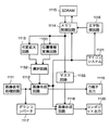
図1は、本発明の一実施例の概略構成ブロック図を示す。画像信号処理回路111は、図7に示すレンズ401、撮像素子402及びカメラ信号処理回路403からなり、HD(高品位)デジタル画像信号を出力する。即ち、画像信号処理回路111が出力するHDデジタル画像信号は、レンズ401によりCCD撮像素子402に結像することによりCCD撮像素子402から出力される映像信号をカメラ信号処理回路403でHD信号処理したものである。
FIG. 1 shows a schematic block diagram of an embodiment of the present invention. The image
画像信号処理回路111から出力されたデジタル信号は、2系統に分離されその一方は、ダウンコンバート回路117によりHDフォーマットからSDフォーマットにダウンコンバートされ、画像合成回路118でSDビットマップを合成され、コンポジット出力120となる。もう一方の信号は、画像合成回路112によりHDビットマップを合成され、D端子出力119となる。
The digital signal output from the image
マイコンシステム121は、図6に示すように、マイクロコンピュータ(マイコン)311とマイコン311を動作させるためのプログラムを記憶するメモリ312から構成されている。メモリ312上には、キャラクタ情報313も記憶されている。更に、マイコン311は、スイッチ手段314で制御され、各種デバイス315を制御する。このマイコンシステム121は、文字制御回路116(図1)を制御し、キャラクタ情報をSDRAM115に展開して一時記憶させ、ビットマップを表示させる。
As shown in FIG. 6, the
また、マイコンシステム121は、表示位置の情報によりメモリ制御回路114を動作させる。メモリ制御回路114からのビットマップ情報は、二つに分離される。分離された一方の情報は、可変拡大回路113で図5にある様に縦横2倍の4倍角キャラクタに変換され、HDデジタル信号に対応したHDキャラクタとなり、画像合成回路112で生成され、マイコンシステム121からのエリアに応じた表示のオン/オフ制御の下で画像データに合成され、D端子出力119となる。他方の情報は、画像合成回路118で生成され、マイコン311からのエリアに応じた表示のオン/オフ制御の下で画像データに合成され、コンポジット出力120となる。
Further, the
各出力は、図7に示すコンポジット出力回路410を通して、アスペクト比4:3のスタンダードモニタ412に出力される。D端子出力119は、D端子出力回路411を介してHDモニタ413に印加される。
Each output is output to the
実際に記録される信号は、カメラ信号処理回路403及び記録信号処理回路405を介して、磁気テープ406などの磁気媒体、又は、SDカード407などの外部メモリ回路に記録され、又は、USB408を介して外部接続機器に出力される。
The actually recorded signal is recorded on a magnetic medium such as
記録信号処理は、SDフォーマットとHDフォーマットの両方に対応する。再生時は、各フォーマットから変換されたデジタル画像信号を再生信号処理回路でHD又はSDデジタル画像信号に変換し、記録時と同様にビデオ出力にビットマップを重畳する為のビットマップ信号処理回路404を介して、それぞれ、HDモニタ413又はスタンダードモニタ412に出力される。
The recording signal processing corresponds to both the SD format and the HD format. At the time of reproduction, a digital image signal converted from each format is converted into an HD or SD digital image signal by a reproduction signal processing circuit, and a bitmap
図8を参照して、表示エリアとビットマップエリアの関係を説明する。SD時のモニタ表示エリア503の少し内側にSD時のビットマップ表示エリア504が位置し、左右上下均等に文字を表示できる。キャラクタの同じビットマップを使ってHD信号に4倍角として表示した場合、SD時のビットマップを上下左右にそれぞれ2倍した表示エリア502に文字を表示可能である。この時のHDモニタの表示エリア501は、表示エリア502を囲むように配置される。これらを通常モニタに表示すると、図10に例示するような表示となる。HDモニタでは、図8に示すように表示される。 The relationship between the display area and the bitmap area will be described with reference to FIG. A bit map display area 504 at the time of SD is located slightly inside the monitor display area 503 at the time of SD, so that characters can be displayed evenly from left to right and up and down. When the same bit map of the character is used to display the HD signal as a quadruple angle, the character can be displayed in the display area 502 in which the bit map at the time of SD is doubled vertically and horizontally. The display area 501 of the HD monitor at this time is arranged so as to surround the display area 502. When these are displayed on a normal monitor, the display illustrated in FIG. 10 is obtained. On the HD monitor, it is displayed as shown in FIG.
図2は、本発明の第2実施例の概略構成ブロック図を示す。画像信号処理回路211は、図7に示すレンズ401、撮像素子402及びカメラ信号処理回路403からなり、HD(高品位)デジタル画像信号を出力する。即ち、画像信号処理回路211が出力するHDデジタル画像信号は、レンズ401によりCCD撮像素子402に結像することによりCCD撮像素子402から出力される映像信号をカメラ信号処理回路403でHD信号処理したものである。
FIG. 2 shows a schematic block diagram of the second embodiment of the present invention. The image
画像信号処理回路211から出力されたデジタル信号は、2系統に分離されその一方は、ダウンコンバート回路217によりHDフォーマットからSDフォーマットにダウンコンバートされ、画像合成回路218でSDビットマップを合成され、コンポジット出力220となる。もう一方の信号は、画像合成回路212によりHDビットマップを合成され、D端子出力219となる。
The digital signal output from the image
マイコンシステム221は、図6に示すように、マイクロコンピュータ(マイコン)311とマイコン311を動作させるためのプログラムを記憶するメモリ312から構成されている。メモリ312上には、キャラクタ情報313も記憶されている。更に、マイコン311は、スイッチ手段314で制御され、各種デバイス315を制御する。このマイコンシステム221は、文字制御回路216を制御し、キャラクタ情報をSDRAM215に展開して一時記憶させ、ビットマップを表示させる。
As shown in FIG. 6, the
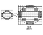
また、マイコンシステム221は、表示位置の情報によりメモリ制御回路214を動作させる。メモリ制御回路214からのビットマップ情報は、二つに分離される。分離された一方の情報は、可変拡大回路213で図4にある様に縦横1/2倍の1/4倍角キャラクタに変換される。ライン間引きでは画像が乱れるため4画素平均間引きで縮小キャラクターが生成される。これにより、SDデジタル信号に対応したSDキャラクタとなり、画像合成回路218で生成され、マイコンシステム221からのエリアに応じた表示のオン/オフ制御の下で画像データに合成され、コンポジット出力220となる。他方の情報は、画像合成回路212で生成され、マイコンシステム221からのエリアに応じた表示のオン/オフ制御の下で画像データに合成され、D端子出力219となる。
Further, the
各出力は、図7に示すコンポジット出力回路410を通して、アスペクト比4:3のスタンダードモニタ412に出力される。D端子出力219は、D端子出力回路411を介してHDモニタ413に印加される。
Each output is output to the
実際に記録される信号は、カメラ信号処理回路403及び記録信号処理回路405を介して、磁気テープ406などの磁気媒体、又は、SDカード407などの外部メモリ回路に記録され、又は、USB408を介して外部接続機器に出力される。
The actually recorded signal is recorded on a magnetic medium such as
記録信号処理は、SDフォーマットとHDフォーマットの両方に対応する。再生時は、各フォーマットから変換されたデジタル画像信号を再生信号処理回路でHD又はSDデジタル画像信号に変換し、記録時と同様にビデオ出力にビットマップを重畳する為のビットマップ信号処理回路404を介して、それぞれ、HDモニタ413又はスタンダードモニタ412に出力される。
The recording signal processing corresponds to both the SD format and the HD format. At the time of reproduction, a digital image signal converted from each format is converted into an HD or SD digital image signal by a reproduction signal processing circuit, and a bitmap
図8を参照して、表示エリアとビットマップエリアの関係を説明する。SD時のモニタ表示エリア503の少し内側にSD時のビットマップ表示エリア504が位置し、左右上下均等に文字を表示できる。キャラクタの同じビットマップを使ってHD信号に4倍角として表示した場合、SD時のビットマップを上下左右にそれぞれ2倍した表示エリア502に文字を表示可能である。この時のHDモニタの表示エリア501は、表示エリア502を囲むように配置される。これらを通常モニタに表示すると、図10に例示するような表示となる。HDモニタでは、図9に示すように表示される。 The relationship between the display area and the bitmap area will be described with reference to FIG. A bit map display area 504 at the time of SD is located slightly inside the monitor display area 503 at the time of SD, so that characters can be displayed evenly from left to right and up and down. When the same bit map of the character is used to display the HD signal as a quadruple angle, the character can be displayed in the display area 502 in which the bit map at the time of SD is doubled vertically and horizontally. The display area 501 of the HD monitor at this time is arranged so as to surround the display area 502. When these are displayed on a normal monitor, the display illustrated in FIG. 10 is obtained. On the HD monitor, it is displayed as shown in FIG.
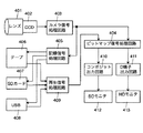
図3は、本発明の第3実施例の概略構成ブロック図を示す。画像信号処理回路1111は、図7に示すレンズ401、撮像素子402及びカメラ信号処理回路403からなり、HD(高品位)デジタル画像信号を出力する。即ち、画像信号処理回路1111が出力するHDデジタル画像信号は、レンズ401によりCCD撮像素子402に結像することによりCCD撮像素子402から出力される映像信号をカメラ信号処理回路403でHD信号処理したものである。
FIG. 3 shows a schematic block diagram of a third embodiment of the present invention. The image
画像信号処理回路1111から出力されたデジタル信号は、2系統に分離されその一方は、ダウンコンバート回路1117によりHDフォーマットからSDフォーマットにダウンコンバートされ、画像合成回路1118でSDビットマップを合成され、コンポジット出力1120となる。もう一方の信号は、画像合成回路1112によりHDビットマップを合成され、D端子出力1119となる。
The digital signal output from the image
マイコンシステム1121は、図6に示すように、マイクロコンピュータ(マイコン)311とマイコン311を動作させるためのプログラムを記憶するメモリ312から構成されている。メモリ312上には、キャラクタ情報313も記憶されている。更に、マイコン311は、スイッチ手段314で制御され、各種デバイス315を制御する。このマイコンシステム1121は、文字制御回路1116を制御し、キャラクタ情報をSDRAM1115に展開して一時記憶させ、ビットマップを表示させる。
As shown in FIG. 6, the
また、マイコンシステム1121は、表示位置の情報によりメモリ制御回路1114を動作させる。メモリ制御回路1114からのビットマップ情報は、三つに分離される。分離された第一の情報は、可変拡大回路1113で図5にある様に縦横2倍の4倍角キャラクタに変換され、HDデジタル信号に対応したHDキャラクタとなる。分離された第二の情報は、位置情報変換手段1131でビットマップの位置をSD時のビットマップ表示エリアを右上に移動した時で表される様な位置505、又は、SD時のビットマップ表示エリアを左下に移動した時で表される様な位置506に移動してHDデジタル信号に合成するため、HDキャラクタの1/4倍角の大きさのキャラクタとなる。このHDキャラクタと1/4倍角のキャラクタが選択回路1132で部分的に選択され、画像合成回路1112で生成され、マイコン回路1121からのエリアに応じた表示のオン/オフ制御の下で画像データに合成され、D端子出力1119となる。
Further, the
分離された第三の情報は、マスク回路1133で不要な部分をマスクされ、不要部分を削除したデータとなる。画像合成回路1118は、マイコンシステム1121からのエリアに応じた表示のオン/オフ制御の下で、画像データを合成し、コンポジット出力1120を出力する。
The separated third information is data in which unnecessary portions are masked by the
各出力は、図7に示すコンポジット出力回路410を通して、アスペクト比4:3のスタンダードモニタ412に出力される。D端子出力1119は、D端子出力回路411を介してHDモニタ413に印加される。
Each output is output to the
実際に記録される信号は、カメラ信号処理回路403及び記録信号処理回路405を介して、磁気テープ406などの磁気媒体、又は、SDカード407などの外部メモリ回路に記録され、又は、USB408を介して外部接続機器に出力される。
The actually recorded signal is recorded on a magnetic medium such as
記録信号処理は、SDフォーマットとHDフォーマットの両方に対応する。再生時は、各フォーマットから変換されたデジタル画像信号を再生信号処理回路でHD又はSDデジタル画像信号に変換し、記録時と同様にビデオ出力にビットマップを重畳する為のビットマップ信号処理回路404を介して、それぞれ、HDモニタ413又はスタンダードモニタ412に出力される。
The recording signal processing corresponds to both the SD format and the HD format. At the time of reproduction, a digital image signal converted from each format is converted into an HD or SD digital image signal by a reproduction signal processing circuit, and a bitmap
図8を参照して、表示エリアとビットマップエリアの関係を説明する。SD時のモニタ表示エリア503の少し内側にSD時のビットマップ表示エリア504が位置し、左右上下均等に文字を表示できる。キャラクタの同じビットマップを使ってHD信号に4倍角として表示した場合、SD時のビットマップを上下左右にそれぞれ2倍した表示エリア502に文字を表示可能である。更に、位置情報変換回路1131を用いることで、HDモニタの表示エリア501内で、SD時のビットマップ表示エリアを右上に移動した時で表される様な位置505、又は、SD時のビットマップ表示エリアを左下に移動した時で表される様な位置506に移動して、小さい文字を表示する事が可能となる。
The relationship between the display area and the bitmap area will be described with reference to FIG. A bit map display area 504 at the time of SD is located slightly inside the monitor display area 503 at the time of SD, so that characters can be displayed evenly from left to right and up and down. When the same bit map of the character is used to display the HD signal as a quadruple angle, the character can be displayed in the display area 502 in which the bit map at the time of SD is doubled vertically and horizontally. Further, by using the position
通常モニタでは、図10に示すように表示される。HDモニタでは、図11に示すように表示されるが、選択回路1132により、四角く囲んだ部分802,803は同時には表示しないで、四角く囲んだ部分804を表示する。
On the normal monitor, the display is as shown in FIG. In the HD monitor, the screen is displayed as shown in FIG. 11, but the
特定の説明用の実施例を参照して本発明を説明したが、特許請求の範囲に規定される本発明の技術的範囲を逸脱しないで、上述の実施例に種々の変更・修整を施しうることは、本発明の属する技術分野の技術者にとって自明であり、このような変更・修整も本発明の技術的範囲に含まれる。 Although the invention has been described with reference to specific illustrative embodiments, various modifications and alterations may be made to the above-described embodiments without departing from the scope of the invention as defined in the claims. This is obvious to an engineer in the technical field to which the present invention belongs, and such changes and modifications are also included in the technical scope of the present invention.
111:画像信号処理回路
113:可変拡大回路
114:メモリ制御回路
115:SDRAM
116:文字制御回路
117:ダウンコンバート回路
118:画像合成回路
119:D端子出力
120:コンポジット出力
121:マイコンシステム
211:画像信号処理回路
212:画像合成回路
213:可変拡大回路
214:メモリ制御回路
215:SDRAM
216:文字制御回路
217:ダウンコンバート回路
218:画像合成回路
219:D端子出力
220:コンポジット出力
221:マイコンシステム
311:マイクロコンピュータ(マイコン)
312:メモリ
313:キャラクタ情報
314:スイッチ手段
315:各種デバイス
401:レンズ
402:撮像素子
403:カメラ信号処理回路
404:ビットマップ信号処理回路
405:記録信号処理回路
406:磁気テープ
407:SDカード
408:USB
410:コンポジット出力回路
411:D端子出力回路
412:スタンダードモニタ
413:HDモニタ
911:ワイド用パーツ
912:共通パーツ
913:ノーマルパーツ
1111:画像信号処理回路
1112:画像合成回路
1113:可変拡大回路
1114:メモリ制御回路
1115:SDRAM
1116:文字制御回路
1117:ダウンコンバート回路
1118:画像合成回路
1119:D端子出力
1120:コンポジット出力
1121:マイコンシステム
1131:位置情報変換手段
1132:選択回路
1133:マスク回路
111: Image signal processing circuit 113: Variable enlargement circuit 114: Memory control circuit 115: SDRAM
116: Character control circuit 117: Down-conversion circuit 118: Image composition circuit 119: D terminal output 120: Composite output 121: Microcomputer system 211: Image signal processing circuit 212: Image composition circuit 213: Variable enlargement circuit 214: Memory control circuit 215 : SDRAM
216: Character control circuit 217: Down-conversion circuit 218: Image composition circuit 219: D terminal output 220: Composite output 221: Microcomputer system 311: Microcomputer (microcomputer)
312: Memory 313: Character information 314: Switch means 315: Various devices 401: Lens 402: Image sensor 403: Camera signal processing circuit 404: Bitmap signal processing circuit 405: Recording signal processing circuit 406: Magnetic tape 407: SD card 408 : USB
410: Composite output circuit 411: D terminal output circuit 412: Standard monitor 413: HD monitor 911: Wide part 912: Common part 913: Normal part 1111: Image signal processing circuit 1112: Image composition circuit 1113: Variable enlargement circuit 1114: Memory control circuit 1115: SDRAM
1116: Character control circuit 1117: Down-conversion circuit 1118: Image composition circuit 1119: D terminal output 1120: Composite output 1121: Microcomputer system 1131: Position information conversion means 1132: Selection circuit 1133: Mask circuit
Claims (14)
前記入力手段により入力された前記第1のビデオフォーマットの映像信号を前記第1の解像度よりも低い第2の解像度の第2のビデオフォーマットの映像信号に変換する映像信号変換手段と、
文字画像情報を保持するメモリと、
前記第1のビデオフォーマットの映像信号に前記メモリより読み出した文字画像情報を合成する第1の合成手段と、
前記第1の合成手段により合成された信号を出力する第1の出力手段と、
前記メモリより読み出した文字画像情報を2×2の4画素単位に縮小する縮小手段と、
前記第2のビデオフォーマットの映像信号に前記縮小手段により縮小された文字画像情報を合成する第2の合成手段と、
前記第1の出力手段による出力と並列して、前記第2の合成手段により合成された信号を出力する、前記第1の出力手段とは別の第2の出力手段
とを有することを特徴とする映像信号処理装置。 Input means for inputting a video signal of a first video format having a first resolution;
Video signal conversion means for converting the video signal of the first video format input by the input means into a video signal of a second video format having a second resolution lower than the first resolution;
A memory for storing character image information;
First combining means for combining the character image information read from the memory with the video signal of the first video format;
First output means for outputting a signal synthesized by the first synthesis means;
Reduction means for reducing the character image information read out from the memory in units of 2 × 2 pixels ;
Second combining means for combining the image signal of the second video format with the character image information reduced by the reducing means;
And a second output means different from the first output means for outputting the signal synthesized by the second synthesis means in parallel with the output by the first output means. Video signal processing device.
前記入力手段により入力された前記第1のビデオフォーマットの映像信号を前記第1の解像度よりも低い第2の解像度の第2のビデオフォーマットの映像信号に変換する映像信号変換手段と、
文字画像情報を保持するメモリと、
前記第2のビデオフォーマットの映像信号に前記メモリより読み出した文字画像情報を合成する第1の合成手段と、
前記第1の合成手段により合成された信号を出力する第1の出力手段と、
前記メモリより読み出した文字画像情報の合成位置に関する情報を変更する位置情報変更手段と、
前記メモリより読み出した文字画像情報を拡大する拡大手段と、
前記位置情報変更手段により合成位置に関する情報が変更された文字画像情報と前記拡大手段からの文字画像情報のうちの一部を選択する選択手段と、
前記第1のビデオフォーマットの映像信号に前記選択手段により選択された文字画像情報を合成する第2の合成手段と、
前記第2の合成手段により合成された信号を出力する第2の出力手段
とを有することを特徴とする映像信号処理装置。 Input means for inputting a video signal of a first video format having a first resolution;
Video signal conversion means for converting the video signal of the first video format input by the input means into a video signal of a second video format having a second resolution lower than the first resolution;
A memory for storing character image information;
First synthesizing means for synthesizing the character image information read from the memory with the video signal of the second video format;
First output means for outputting a signal synthesized by the first synthesis means;
Position information changing means for changing information related to the combined position of the character image information read from the memory;
Enlarging means for enlarging the character image information read from the memory;
Selecting means for selecting part of the character image information in which the information on the composite position is changed by the position information changing means and the character image information from the enlarging means;
Second synthesizing means for synthesizing the character image information selected by the selecting means with the video signal of the first video format;
And a second output means for outputting the signal synthesized by the second synthesis means.
前記入力手段により入力された前記第1のビデオフォーマットの映像信号を前記第1の解像度よりも低い第2の解像度の第2のビデオフォーマットの映像信号に変換する映像信号変換手段と、
文字画像情報を保持するメモリと、
前記第2のビデオフォーマットの映像信号に前記メモリより読み出した文字画像情報を合成する第1の合成手段と、
前記第1の合成手段により合成された信号を出力する第1の出力手段と、
前記メモリより読み出した文字画像情報を拡大する拡大手段と、
前記拡大手段により拡大された文字画像情報と、前記メモリより読み出した文字画像情報の一方を選択する選択手段と、
前記第1のビデオフォーマットの映像信号に前記選択手段により選択された文字画像情報を合成する第2の合成手段と、
前記第1の出力手段による出力と並列して、前記第2の合成手段により合成された信号を出力する、前記第1の出力手段とは別の第2の出力手段
とを有することを特徴とする映像信号処理装置。 Input means for inputting a video signal of a first video format having a first resolution;
Video signal conversion means for converting the video signal of the first video format input by the input means into a video signal of a second video format having a second resolution lower than the first resolution;
A memory for storing character image information;
First synthesizing means for synthesizing the character image information read from the memory with the video signal of the second video format;
First output means for outputting a signal synthesized by the first synthesis means;
Enlarging means for enlarging the character image information read from the memory;
Selection means for selecting one of the character image information enlarged by the enlargement means and the character image information read from the memory;
Second synthesizing means for synthesizing the character image information selected by the selecting means with the video signal of the first video format;
And a second output means different from the first output means for outputting the signal synthesized by the second synthesis means in parallel with the output by the first output means. Video signal processing device.
前記入力手段により入力された前記第1のビデオフォーマットの映像信号を前記第1の解像度よりも低い第2の解像度の第2のビデオフォーマットの映像信号に変換する映像信号変換手段と、
文字画像情報を保持するメモリと、
前記第2のビデオフォーマットの映像信号に前記メモリより読み出した文字画像情報を合成する第1の合成手段と、
前記第1の合成手段により合成された信号を出力する第1の出力手段と、
前記メモリより読み出した文字画像情報を拡大する拡大手段と、
前記第1のビデオフォーマットの映像信号に前記拡大手段により拡大された文字画像情報を合成する第2の合成手段と、
前記第2の合成手段により合成された信号を出力する第2の出力手段と、
前記第1のビデオフォーマットの映像信号に前記文字画像情報を合成する際に、合成する位置に応じて前記文字画像情報の表示のオンオフを切換えるよう前記第2の合成手段を制御する制御手段
とを有することを特徴とする映像信号処理装置。 Input means for inputting a video signal of a first video format having a first resolution;
Video signal conversion means for converting the video signal of the first video format input by the input means into a video signal of a second video format having a second resolution lower than the first resolution;
A memory for storing character image information;
First synthesizing means for synthesizing the character image information read from the memory with the video signal of the second video format;
First output means for outputting a signal synthesized by the first synthesis means;
Enlarging means for enlarging the character image information read from the memory;
Second synthesizing means for synthesizing the character image information enlarged by the enlarging means with the video signal of the first video format;
Second output means for outputting the signal synthesized by the second synthesis means;
Control means for controlling the second combining means so as to switch on / off the display of the character image information in accordance with a position to be combined when the character image information is combined with the video signal of the first video format. A video signal processing apparatus comprising:
前記第1のビデオフォーマットの映像信号に、文字画像情報を保持するメモリより読み出した前記文字画像情報を合成する第1の合成ステップと、
前記メモリより読み出した前記文字画像情報を2×2の4画素単位に縮小する縮小ステップと、
前記第2のビデオフォーマットの映像信号に前記縮小ステップにより縮小された文字画像情報を合成する第2の合成ステップと、
前記第1の合成ステップにより合成された信号及び前記第2の合成ステップにより合成された信号を互いに異なる出力手段から出力するステップ
とを有することを特徴とする映像信号処理方法。 A video signal converting step of converting a video signal of a first video format having a first resolution into a video signal having a second video format having a second resolution lower than the first resolution;
A first synthesizing step of synthesizing the character image information read from a memory holding character image information with the video signal of the first video format;
A reduction step of reducing the character image information read from the memory into 2 × 2 pixel units ;
A second combining step of combining the image signal of the second video format with the character image information reduced by the reducing step;
A video signal processing method comprising: outputting the signal synthesized by the first synthesis step and the signal synthesized by the second synthesis step from different output means.
前記第2のビデオフォーマットの映像信号に、文字画像情報を保持するメモリより読み出した前記文字画像情報を合成する第1の合成ステップと、
前記メモリより読み出した前記文字画像情報の合成位置に関する情報を変更する位置情報変更ステップと、
前記第1のビデオフォーマットの映像信号に、前記位置情報変更ステップにより変更された合成位置に関する情報に基づいて前記文字画像情報を合成する第2の合成ステップと、
前記第1の合成ステップにより合成された信号及び前記第2の合成ステップにより合成された信号を出力するステップと、
前記第1のビデオフォーマットの映像信号に前記文字画像情報を合成する際に、合成する位置に応じて前記文字画像情報の表示のオンオフを切換えるよう前記第2の合成ステップを制御する制御ステップ
とを有することを特徴とする映像信号処理方法。 A video signal converting step of converting a video signal of a first video format having a first resolution into a video signal having a second video format having a second resolution lower than the first resolution;
A first synthesis step of synthesizing the character image information read from a memory holding character image information with the video signal of the second video format;
A position information changing step for changing information related to the composition position of the character image information read from the memory;
A second synthesizing step of synthesizing the character image information with the video signal of the first video format based on information relating to the synthesizing position changed by the position information changing step;
Outputting the signal synthesized by the first synthesis step and the signal synthesized by the second synthesis step ;
A control step of controlling the second combining step so as to switch on / off the display of the character image information in accordance with a position to be combined when the character image information is combined with the video signal of the first video format. A video signal processing method characterized by comprising:
前記第2のビデオフォーマットの映像信号に、文字画像情報を保持するメモリより読み出した前記文字画像情報を合成する第1の合成ステップと、
前記メモリより読み出した前記文字画像情報を拡大する拡大ステップと、
前記拡大ステップにより拡大された文字画像情報と、前記メモリより読み出した前記文字画像情報の一方を選択する選択ステップと、
前記第1のビデオフォーマットの映像信号に前記選択ステップにより選択された文字画像情報を合成する第2の合成ステップと、
前記第1の合成ステップにより合成された信号及び前記第2の合成ステップにより合成された信号を互いに異なる出力手段から出力するステップ
とを有することを特徴とする映像信号処理方法。 A video signal converting step of converting a video signal of a first video format having a first resolution into a video signal having a second video format having a second resolution lower than the first resolution;
A first synthesis step of synthesizing the character image information read from a memory holding character image information with the video signal of the second video format;
An enlargement step of enlarging the character image information read from the memory;
A selection step of selecting one of the character image information enlarged by the enlargement step and the character image information read from the memory;
A second synthesis step of synthesizing the character image information selected in the selection step with the video signal of the first video format;
A video signal processing method comprising: outputting the signal synthesized by the first synthesis step and the signal synthesized by the second synthesis step from different output means.
前記第2のビデオフォーマットの映像信号に、文字画像情報を保持するメモリより読み出した前記文字画像情報を合成する第1の合成ステップと、
前記メモリより読み出した前記文字画像情報を拡大する拡大ステップと、
前記第1のビデオフォーマットの映像信号に前記拡大ステップにより拡大された文字画像情報を合成する第2の合成ステップと、
前記第1の合成ステップにより合成された信号及び前記第2の合成ステップにより合成された信号を出力するステップと、
前記第1のビデオフォーマットの映像信号に前記文字画像情報を合成する際に、合成する位置に応じて前記文字画像情報の表示のオンオフを切換えるよう前記第2の合成ステップを制御する制御ステップ
とを有することを特徴とする映像信号処理方法。 A video signal converting step of converting a video signal of a first video format having a first resolution into a video signal having a second video format having a second resolution lower than the first resolution;
A first synthesis step of synthesizing the character image information read from a memory holding character image information with the video signal of the second video format;
An enlargement step of enlarging the character image information read from the memory;
A second combining step of combining the image signal of the first video format with the character image information expanded by the expanding step;
Outputting the signal synthesized by the first synthesis step and the signal synthesized by the second synthesis step;
A control step of controlling the second combining step so as to switch on / off the display of the character image information in accordance with the position to be combined when the character image information is combined with the video signal of the first video format. A video signal processing method comprising:
Priority Applications (2)
| Application Number | Priority Date | Filing Date | Title |
|---|---|---|---|
| JP2004210592A JP4401884B2 (en) | 2004-07-16 | 2004-07-16 | Video signal processing apparatus and method |
| US11/182,922 US7389004B2 (en) | 2004-07-16 | 2005-07-15 | Image processing apparatus |
Applications Claiming Priority (1)
| Application Number | Priority Date | Filing Date | Title |
|---|---|---|---|
| JP2004210592A JP4401884B2 (en) | 2004-07-16 | 2004-07-16 | Video signal processing apparatus and method |
Publications (3)
| Publication Number | Publication Date |
|---|---|
| JP2006030683A JP2006030683A (en) | 2006-02-02 |
| JP2006030683A5 JP2006030683A5 (en) | 2007-08-16 |
| JP4401884B2 true JP4401884B2 (en) | 2010-01-20 |
Family
ID=35599017
Family Applications (1)
| Application Number | Title | Priority Date | Filing Date |
|---|---|---|---|
| JP2004210592A Expired - Fee Related JP4401884B2 (en) | 2004-07-16 | 2004-07-16 | Video signal processing apparatus and method |
Country Status (2)
| Country | Link |
|---|---|
| US (1) | US7389004B2 (en) |
| JP (1) | JP4401884B2 (en) |
Families Citing this family (3)
| Publication number | Priority date | Publication date | Assignee | Title |
|---|---|---|---|---|
| KR101207148B1 (en) | 2007-09-28 | 2012-11-30 | 리달, 아이엔씨. | A molded and shaped acoustical insulating vehicle panel and method of making the same |
| JP5718012B2 (en) * | 2010-10-13 | 2015-05-13 | オリンパス株式会社 | Scanning laser microscope |
| CN106105177B (en) * | 2014-06-10 | 2019-09-27 | 松下知识产权经营株式会社 | Transform method and converting means |
Family Cites Families (11)
| Publication number | Priority date | Publication date | Assignee | Title |
|---|---|---|---|---|
| JPH10124021A (en) | 1996-10-16 | 1998-05-15 | Sony Corp | Image processor, image processing method and display system |
| JP2001042852A (en) * | 1999-05-21 | 2001-02-16 | Canon Inc | Display device, display method and computer-readable storage medium |
| JP2001016521A (en) * | 1999-06-30 | 2001-01-19 | Matsushita Electric Ind Co Ltd | Digital video reception display device |
| JP2001134262A (en) * | 1999-11-08 | 2001-05-18 | Canon Inc | Image display device and method thereof and storage medium |
| JP2001275043A (en) * | 2000-03-24 | 2001-10-05 | Matsushita Electric Ind Co Ltd | Recording device |
| JP3821641B2 (en) * | 2000-09-29 | 2006-09-13 | 松下電器産業株式会社 | On-screen display device |
| JP4215423B2 (en) * | 2000-10-19 | 2009-01-28 | 三洋電機株式会社 | Image data output device |
| US7219309B2 (en) * | 2001-05-02 | 2007-05-15 | Bitstream Inc. | Innovations for the display of web pages |
| JP5259032B2 (en) * | 2001-07-13 | 2013-08-07 | オリンパス株式会社 | Image processing device |
| JP3564087B2 (en) * | 2001-08-20 | 2004-09-08 | キヤノン株式会社 | Video recording and playback device |
| JP2004029263A (en) * | 2002-06-25 | 2004-01-29 | Matsushita Electric Ind Co Ltd | On-screen display device |
-
2004
- 2004-07-16 JP JP2004210592A patent/JP4401884B2/en not_active Expired - Fee Related
-
2005
- 2005-07-15 US US11/182,922 patent/US7389004B2/en not_active Expired - Fee Related
Also Published As
| Publication number | Publication date |
|---|---|
| US20060012706A1 (en) | 2006-01-19 |
| JP2006030683A (en) | 2006-02-02 |
| US7389004B2 (en) | 2008-06-17 |
Similar Documents
| Publication | Publication Date | Title |
|---|---|---|
| JP4919978B2 (en) | Distortion correction device | |
| JP4593820B2 (en) | Imaging apparatus, image processing apparatus, and image processing method | |
| JP4515559B2 (en) | Image data recording apparatus and method, and zoom image reproducing apparatus and method | |
| WO2004090860A1 (en) | Video combining circuit | |
| JP4410981B2 (en) | Video signal processing apparatus and method | |
| JP4652210B2 (en) | Image data output control device | |
| JP4401884B2 (en) | Video signal processing apparatus and method | |
| JP2008227562A (en) | Image processor, camera apparatus and camera system | |
| JP4641515B2 (en) | Image reproducing apparatus and image reproducing method | |
| US20050140990A1 (en) | Image processing apparatus and method and image data display method for digital camera | |
| JP2007221295A (en) | Camera device and recording format | |
| JP2007267177A (en) | Imaging apparatus | |
| JP2000209512A (en) | Electronic zoom circuit | |
| JP2002354299A (en) | Digital still camera | |
| JP3821641B2 (en) | On-screen display device | |
| JP5645343B2 (en) | Imaging device | |
| JP4239811B2 (en) | Imaging device | |
| JP2006211037A (en) | Image processing method and apparatus | |
| JP3543657B2 (en) | Electronic zoom circuit | |
| JP2004282305A (en) | Image processing system | |
| JP4804562B2 (en) | Video signal processing apparatus and method | |
| JP4140142B2 (en) | Image composition apparatus and method, and imaging apparatus | |
| JP2003116055A (en) | Video output apparatus | |
| WO2012011211A1 (en) | Thumbnail image generation device, magnified image generation device, thumbnail image generation method, and magnified image generation method | |
| JP5008380B2 (en) | Image processing apparatus and image processing method |
Legal Events
| Date | Code | Title | Description |
|---|---|---|---|
| A521 | Request for written amendment filed |
Free format text: JAPANESE INTERMEDIATE CODE: A523 Effective date: 20070628 |
|
| A621 | Written request for application examination |
Free format text: JAPANESE INTERMEDIATE CODE: A621 Effective date: 20070628 |
|
| A977 | Report on retrieval |
Free format text: JAPANESE INTERMEDIATE CODE: A971007 Effective date: 20090625 |
|
| A131 | Notification of reasons for refusal |
Free format text: JAPANESE INTERMEDIATE CODE: A131 Effective date: 20090701 |
|
| A521 | Request for written amendment filed |
Free format text: JAPANESE INTERMEDIATE CODE: A523 Effective date: 20090826 |
|
| TRDD | Decision of grant or rejection written | ||
| A01 | Written decision to grant a patent or to grant a registration (utility model) |
Free format text: JAPANESE INTERMEDIATE CODE: A01 Effective date: 20091013 |
|
| A01 | Written decision to grant a patent or to grant a registration (utility model) |
Free format text: JAPANESE INTERMEDIATE CODE: A01 |
|
| A61 | First payment of annual fees (during grant procedure) |
Free format text: JAPANESE INTERMEDIATE CODE: A61 Effective date: 20091028 |
|
| R150 | Certificate of patent or registration of utility model |
Ref document number: 4401884 Country of ref document: JP Free format text: JAPANESE INTERMEDIATE CODE: R150 Free format text: JAPANESE INTERMEDIATE CODE: R150 |
|
| FPAY | Renewal fee payment (event date is renewal date of database) |
Free format text: PAYMENT UNTIL: 20121106 Year of fee payment: 3 |
|
| FPAY | Renewal fee payment (event date is renewal date of database) |
Free format text: PAYMENT UNTIL: 20131106 Year of fee payment: 4 |
|
| RD03 | Notification of appointment of power of attorney |
Free format text: JAPANESE INTERMEDIATE CODE: R3D03 |
|
| LAPS | Cancellation because of no payment of annual fees |