JP4401676B2 - Positioning mechanism for MRI compatible biopsy device - Google Patents
Positioning mechanism for MRI compatible biopsy device Download PDFInfo
- Publication number
- JP4401676B2 JP4401676B2 JP2003117348A JP2003117348A JP4401676B2 JP 4401676 B2 JP4401676 B2 JP 4401676B2 JP 2003117348 A JP2003117348 A JP 2003117348A JP 2003117348 A JP2003117348 A JP 2003117348A JP 4401676 B2 JP4401676 B2 JP 4401676B2
- Authority
- JP
- Japan
- Prior art keywords
- biopsy
- slide
- probe
- depth
- guide
- Prior art date
- Legal status (The legal status is an assumption and is not a legal conclusion. Google has not performed a legal analysis and makes no representation as to the accuracy of the status listed.)
- Expired - Fee Related
Links
- 238000001574 biopsy Methods 0.000 title claims description 161
- 230000007246 mechanism Effects 0.000 title claims description 25
- 239000000523 sample Substances 0.000 claims description 199
- 230000006835 compression Effects 0.000 claims description 50
- 238000007906 compression Methods 0.000 claims description 50
- NJPPVKZQTLUDBO-UHFFFAOYSA-N novaluron Chemical compound C1=C(Cl)C(OC(F)(F)C(OC(F)(F)F)F)=CC=C1NC(=O)NC(=O)C1=C(F)C=CC=C1F NJPPVKZQTLUDBO-UHFFFAOYSA-N 0.000 claims description 30
- 238000000034 method Methods 0.000 claims description 26
- 239000003550 marker Substances 0.000 claims description 22
- 230000005291 magnetic effect Effects 0.000 claims description 14
- 238000002595 magnetic resonance imaging Methods 0.000 description 64
- 210000001519 tissue Anatomy 0.000 description 52
- 210000000481 breast Anatomy 0.000 description 38
- 238000003780 insertion Methods 0.000 description 28
- 230000037431 insertion Effects 0.000 description 28
- 230000003902 lesion Effects 0.000 description 21
- 230000008901 benefit Effects 0.000 description 11
- 238000003384 imaging method Methods 0.000 description 10
- 238000005070 sampling Methods 0.000 description 10
- 238000011282 treatment Methods 0.000 description 10
- 230000001012 protector Effects 0.000 description 9
- 210000000038 chest Anatomy 0.000 description 7
- 230000001225 therapeutic effect Effects 0.000 description 7
- 206010018852 Haematoma Diseases 0.000 description 6
- 238000005520 cutting process Methods 0.000 description 6
- 239000012530 fluid Substances 0.000 description 6
- 210000004027 cell Anatomy 0.000 description 5
- 238000003745 diagnosis Methods 0.000 description 5
- 229910052751 metal Inorganic materials 0.000 description 5
- 239000002184 metal Substances 0.000 description 5
- 238000012360 testing method Methods 0.000 description 5
- 239000000463 material Substances 0.000 description 4
- 238000003752 polymerase chain reaction Methods 0.000 description 4
- 210000000779 thoracic wall Anatomy 0.000 description 4
- 238000013519 translation Methods 0.000 description 4
- 238000002604 ultrasonography Methods 0.000 description 4
- 206010028980 Neoplasm Diseases 0.000 description 3
- 230000005540 biological transmission Effects 0.000 description 3
- 238000004891 communication Methods 0.000 description 3
- 239000002872 contrast media Substances 0.000 description 3
- 238000010586 diagram Methods 0.000 description 3
- 239000003193 general anesthetic agent Substances 0.000 description 3
- 230000006872 improvement Effects 0.000 description 3
- 102000004169 proteins and genes Human genes 0.000 description 3
- 108090000623 proteins and genes Proteins 0.000 description 3
- 230000005855 radiation Effects 0.000 description 3
- 210000003813 thumb Anatomy 0.000 description 3
- 239000000853 adhesive Substances 0.000 description 2
- 230000001070 adhesive effect Effects 0.000 description 2
- 230000003444 anaesthetic effect Effects 0.000 description 2
- 229940035674 anesthetics Drugs 0.000 description 2
- 201000011510 cancer Diseases 0.000 description 2
- SOYKEARSMXGVTM-UHFFFAOYSA-N chlorphenamine Chemical compound C=1C=CC=NC=1C(CCN(C)C)C1=CC=C(Cl)C=C1 SOYKEARSMXGVTM-UHFFFAOYSA-N 0.000 description 2
- 229960003291 chlorphenamine Drugs 0.000 description 2
- 238000001514 detection method Methods 0.000 description 2
- 238000012377 drug delivery Methods 0.000 description 2
- 235000019589 hardness Nutrition 0.000 description 2
- 239000007788 liquid Substances 0.000 description 2
- 230000003211 malignant effect Effects 0.000 description 2
- 230000037361 pathway Effects 0.000 description 2
- 238000002600 positron emission tomography Methods 0.000 description 2
- 230000001681 protective effect Effects 0.000 description 2
- 210000004872 soft tissue Anatomy 0.000 description 2
- 238000001356 surgical procedure Methods 0.000 description 2
- 238000012285 ultrasound imaging Methods 0.000 description 2
- 102000004127 Cytokines Human genes 0.000 description 1
- 108090000695 Cytokines Proteins 0.000 description 1
- 238000000018 DNA microarray Methods 0.000 description 1
- 239000004606 Fillers/Extenders Substances 0.000 description 1
- 208000032843 Hemorrhage Diseases 0.000 description 1
- 125000002066 L-histidyl group Chemical group [H]N1C([H])=NC(C([H])([H])[C@](C(=O)[*])([H])N([H])[H])=C1[H] 0.000 description 1
- 239000002616 MRI contrast agent Substances 0.000 description 1
- 238000012307 MRI technique Methods 0.000 description 1
- 206010029113 Neovascularisation Diseases 0.000 description 1
- 208000006994 Precancerous Conditions Diseases 0.000 description 1
- 238000001069 Raman spectroscopy Methods 0.000 description 1
- RTAQQCXQSZGOHL-UHFFFAOYSA-N Titanium Chemical compound [Ti] RTAQQCXQSZGOHL-UHFFFAOYSA-N 0.000 description 1
- 229920004738 ULTEM® Polymers 0.000 description 1
- 230000002159 abnormal effect Effects 0.000 description 1
- 230000005856 abnormality Effects 0.000 description 1
- 229910052782 aluminium Inorganic materials 0.000 description 1
- XAGFODPZIPBFFR-UHFFFAOYSA-N aluminium Chemical compound [Al] XAGFODPZIPBFFR-UHFFFAOYSA-N 0.000 description 1
- 238000004458 analytical method Methods 0.000 description 1
- 239000002246 antineoplastic agent Substances 0.000 description 1
- 229940041181 antineoplastic drug Drugs 0.000 description 1
- 230000004888 barrier function Effects 0.000 description 1
- 239000000090 biomarker Substances 0.000 description 1
- 230000000740 bleeding effect Effects 0.000 description 1
- HJJVPARKXDDIQD-UHFFFAOYSA-N bromuconazole Chemical compound ClC1=CC(Cl)=CC=C1C1(CN2N=CN=C2)OCC(Br)C1 HJJVPARKXDDIQD-UHFFFAOYSA-N 0.000 description 1
- 230000004663 cell proliferation Effects 0.000 description 1
- 239000000919 ceramic Substances 0.000 description 1
- 238000012512 characterization method Methods 0.000 description 1
- 238000000701 chemical imaging Methods 0.000 description 1
- 239000003795 chemical substances by application Substances 0.000 description 1
- 238000013170 computed tomography imaging Methods 0.000 description 1
- 210000004748 cultured cell Anatomy 0.000 description 1
- 230000002380 cytological effect Effects 0.000 description 1
- 238000002059 diagnostic imaging Methods 0.000 description 1
- 238000007599 discharging Methods 0.000 description 1
- 238000006073 displacement reaction Methods 0.000 description 1
- 239000003814 drug Substances 0.000 description 1
- 230000000694 effects Effects 0.000 description 1
- 229910000701 elgiloys (Co-Cr-Ni Alloy) Inorganic materials 0.000 description 1
- 102000015694 estrogen receptors Human genes 0.000 description 1
- 108010038795 estrogen receptors Proteins 0.000 description 1
- 230000005294 ferromagnetic effect Effects 0.000 description 1
- 239000000835 fiber Substances 0.000 description 1
- 238000000684 flow cytometry Methods 0.000 description 1
- 239000012634 fragment Substances 0.000 description 1
- 230000008014 freezing Effects 0.000 description 1
- 238000007710 freezing Methods 0.000 description 1
- 230000005251 gamma ray Effects 0.000 description 1
- 230000002068 genetic effect Effects 0.000 description 1
- 239000003102 growth factor Substances 0.000 description 1
- 238000003306 harvesting Methods 0.000 description 1
- 238000003364 immunohistochemistry Methods 0.000 description 1
- 238000002513 implantation Methods 0.000 description 1
- 238000011273 incision biopsy Methods 0.000 description 1
- 238000007386 incisional biopsy Methods 0.000 description 1
- 238000002347 injection Methods 0.000 description 1
- 239000007924 injection Substances 0.000 description 1
- 238000001499 laser induced fluorescence spectroscopy Methods 0.000 description 1
- 238000009607 mammography Methods 0.000 description 1
- 238000004519 manufacturing process Methods 0.000 description 1
- 230000002438 mitochondrial effect Effects 0.000 description 1
- 238000013188 needle biopsy Methods 0.000 description 1
- 210000005036 nerve Anatomy 0.000 description 1
- HLXZNVUGXRDIFK-UHFFFAOYSA-N nickel titanium Chemical compound [Ti].[Ti].[Ti].[Ti].[Ti].[Ti].[Ti].[Ti].[Ti].[Ti].[Ti].[Ni].[Ni].[Ni].[Ni].[Ni].[Ni].[Ni].[Ni].[Ni].[Ni].[Ni].[Ni].[Ni].[Ni] HLXZNVUGXRDIFK-UHFFFAOYSA-N 0.000 description 1
- 229910001000 nickel titanium Inorganic materials 0.000 description 1
- 238000012633 nuclear imaging Methods 0.000 description 1
- 238000010899 nucleation Methods 0.000 description 1
- 238000002559 palpation Methods 0.000 description 1
- 239000012188 paraffin wax Substances 0.000 description 1
- 230000001575 pathological effect Effects 0.000 description 1
- 230000010287 polarization Effects 0.000 description 1
- 238000003825 pressing Methods 0.000 description 1
- 230000008569 process Effects 0.000 description 1
- 238000004393 prognosis Methods 0.000 description 1
- 230000035755 proliferation Effects 0.000 description 1
- 238000001959 radiotherapy Methods 0.000 description 1
- 239000011347 resin Substances 0.000 description 1
- 229920005989 resin Polymers 0.000 description 1
- 238000002603 single-photon emission computed tomography Methods 0.000 description 1
- 238000004611 spectroscopical analysis Methods 0.000 description 1
- 230000000087 stabilizing effect Effects 0.000 description 1
- 229910001220 stainless steel Inorganic materials 0.000 description 1
- 239000010935 stainless steel Substances 0.000 description 1
- 230000001629 suppression Effects 0.000 description 1
- 229940124597 therapeutic agent Drugs 0.000 description 1
- 238000001931 thermography Methods 0.000 description 1
- 210000000115 thoracic cavity Anatomy 0.000 description 1
- 239000010936 titanium Substances 0.000 description 1
- 229910052719 titanium Inorganic materials 0.000 description 1
- 238000003325 tomography Methods 0.000 description 1
Images


Classifications
-
- A—HUMAN NECESSITIES
- A61—MEDICAL OR VETERINARY SCIENCE; HYGIENE
- A61B—DIAGNOSIS; SURGERY; IDENTIFICATION
- A61B10/00—Other methods or instruments for diagnosis, e.g. instruments for taking a cell sample, for biopsy, for vaccination diagnosis; Sex determination; Ovulation-period determination; Throat striking implements
- A61B10/02—Instruments for taking cell samples or for biopsy
- A61B10/0233—Pointed or sharp biopsy instruments
- A61B10/0266—Pointed or sharp biopsy instruments means for severing sample
- A61B10/0275—Pointed or sharp biopsy instruments means for severing sample with sample notch, e.g. on the side of inner stylet
-
- A—HUMAN NECESSITIES
- A61—MEDICAL OR VETERINARY SCIENCE; HYGIENE
- A61B—DIAGNOSIS; SURGERY; IDENTIFICATION
- A61B17/00—Surgical instruments, devices or methods, e.g. tourniquets
- A61B17/34—Trocars; Puncturing needles
- A61B17/3403—Needle locating or guiding means
-
- A—HUMAN NECESSITIES
- A61—MEDICAL OR VETERINARY SCIENCE; HYGIENE
- A61B—DIAGNOSIS; SURGERY; IDENTIFICATION
- A61B5/00—Measuring for diagnostic purposes; Identification of persons
- A61B5/70—Means for positioning the patient in relation to the detecting, measuring or recording means
- A61B5/708—Breast positioning means
-
- A—HUMAN NECESSITIES
- A61—MEDICAL OR VETERINARY SCIENCE; HYGIENE
- A61B—DIAGNOSIS; SURGERY; IDENTIFICATION
- A61B90/00—Instruments, implements or accessories specially adapted for surgery or diagnosis and not covered by any of the groups A61B1/00 - A61B50/00, e.g. for luxation treatment or for protecting wound edges
- A61B90/10—Instruments, implements or accessories specially adapted for surgery or diagnosis and not covered by any of the groups A61B1/00 - A61B50/00, e.g. for luxation treatment or for protecting wound edges for stereotaxic surgery, e.g. frame-based stereotaxis
- A61B90/14—Fixators for body parts, e.g. skull clamps; Constructional details of fixators, e.g. pins
- A61B90/17—Fixators for body parts, e.g. skull clamps; Constructional details of fixators, e.g. pins for soft tissue, e.g. breast-holding devices
-
- A—HUMAN NECESSITIES
- A61—MEDICAL OR VETERINARY SCIENCE; HYGIENE
- A61B—DIAGNOSIS; SURGERY; IDENTIFICATION
- A61B10/00—Other methods or instruments for diagnosis, e.g. instruments for taking a cell sample, for biopsy, for vaccination diagnosis; Sex determination; Ovulation-period determination; Throat striking implements
- A61B10/02—Instruments for taking cell samples or for biopsy
- A61B2010/0208—Biopsy devices with actuators, e.g. with triggered spring mechanisms
-
- A—HUMAN NECESSITIES
- A61—MEDICAL OR VETERINARY SCIENCE; HYGIENE
- A61B—DIAGNOSIS; SURGERY; IDENTIFICATION
- A61B17/00—Surgical instruments, devices or methods, e.g. tourniquets
- A61B2017/00831—Material properties
- A61B2017/00902—Material properties transparent or translucent
- A61B2017/00911—Material properties transparent or translucent for fields applied by a magnetic resonance imaging system
-
- A—HUMAN NECESSITIES
- A61—MEDICAL OR VETERINARY SCIENCE; HYGIENE
- A61B—DIAGNOSIS; SURGERY; IDENTIFICATION
- A61B17/00—Surgical instruments, devices or methods, e.g. tourniquets
- A61B17/34—Trocars; Puncturing needles
- A61B17/3403—Needle locating or guiding means
- A61B2017/3405—Needle locating or guiding means using mechanical guide means
- A61B2017/3411—Needle locating or guiding means using mechanical guide means with a plurality of holes, e.g. holes in matrix arrangement
-
- A—HUMAN NECESSITIES
- A61—MEDICAL OR VETERINARY SCIENCE; HYGIENE
- A61B—DIAGNOSIS; SURGERY; IDENTIFICATION
- A61B17/00—Surgical instruments, devices or methods, e.g. tourniquets
- A61B17/34—Trocars; Puncturing needles
- A61B2017/347—Locking means, e.g. for locking instrument in cannula
-
- A—HUMAN NECESSITIES
- A61—MEDICAL OR VETERINARY SCIENCE; HYGIENE
- A61B—DIAGNOSIS; SURGERY; IDENTIFICATION
- A61B90/00—Instruments, implements or accessories specially adapted for surgery or diagnosis and not covered by any of the groups A61B1/00 - A61B50/00, e.g. for luxation treatment or for protecting wound edges
- A61B90/39—Markers, e.g. radio-opaque or breast lesions markers
- A61B2090/3954—Markers, e.g. radio-opaque or breast lesions markers magnetic, e.g. NMR or MRI
-
- A—HUMAN NECESSITIES
- A61—MEDICAL OR VETERINARY SCIENCE; HYGIENE
- A61B—DIAGNOSIS; SURGERY; IDENTIFICATION
- A61B5/00—Measuring for diagnostic purposes; Identification of persons
- A61B5/05—Detecting, measuring or recording for diagnosis by means of electric currents or magnetic fields; Measuring using microwaves or radio waves
- A61B5/055—Detecting, measuring or recording for diagnosis by means of electric currents or magnetic fields; Measuring using microwaves or radio waves involving electronic [EMR] or nuclear [NMR] magnetic resonance, e.g. magnetic resonance imaging
-
- Y—GENERAL TAGGING OF NEW TECHNOLOGICAL DEVELOPMENTS; GENERAL TAGGING OF CROSS-SECTIONAL TECHNOLOGIES SPANNING OVER SEVERAL SECTIONS OF THE IPC; TECHNICAL SUBJECTS COVERED BY FORMER USPC CROSS-REFERENCE ART COLLECTIONS [XRACs] AND DIGESTS
- Y10—TECHNICAL SUBJECTS COVERED BY FORMER USPC
- Y10S—TECHNICAL SUBJECTS COVERED BY FORMER USPC CROSS-REFERENCE ART COLLECTIONS [XRACs] AND DIGESTS
- Y10S128/00—Surgery
- Y10S128/915—Ultrasound mammography
-
- Y—GENERAL TAGGING OF NEW TECHNOLOGICAL DEVELOPMENTS; GENERAL TAGGING OF CROSS-SECTIONAL TECHNOLOGIES SPANNING OVER SEVERAL SECTIONS OF THE IPC; TECHNICAL SUBJECTS COVERED BY FORMER USPC CROSS-REFERENCE ART COLLECTIONS [XRACs] AND DIGESTS
- Y10—TECHNICAL SUBJECTS COVERED BY FORMER USPC
- Y10S—TECHNICAL SUBJECTS COVERED BY FORMER USPC CROSS-REFERENCE ART COLLECTIONS [XRACs] AND DIGESTS
- Y10S128/00—Surgery
- Y10S128/916—Ultrasound 3-D imaging
Landscapes
- Health & Medical Sciences (AREA)
- Life Sciences & Earth Sciences (AREA)
- Surgery (AREA)
- Biomedical Technology (AREA)
- Medical Informatics (AREA)
- Veterinary Medicine (AREA)
- Public Health (AREA)
- Engineering & Computer Science (AREA)
- General Health & Medical Sciences (AREA)
- Heart & Thoracic Surgery (AREA)
- Pathology (AREA)
- Molecular Biology (AREA)
- Animal Behavior & Ethology (AREA)
- Nuclear Medicine, Radiotherapy & Molecular Imaging (AREA)
- Neurosurgery (AREA)
- Oral & Maxillofacial Surgery (AREA)
- Physics & Mathematics (AREA)
- Biophysics (AREA)
- Magnetic Resonance Imaging Apparatus (AREA)
Description
【0001】
【発明の属する技術分野】
関連出願についてのクロスリファレンス
本願明細書は、2002年4月23に出願の発明の名称が本出願と同一である米国仮特許出願第60/374,728号の恩典を請求するものである。本願明細書は同日に出願された、Hibnerによる名称が「取り外し可能なプローブを備えたMRI適合性生検装置(AN MRI COMPATIBLE BIOPSY DEVICE WITH DETACHABLE PROBE)」及び「MRI装置において最小の侵襲性で実施するための方法(METHOD FOR PERFORMING MINIMALLY INVASIVE BIOPSY IN AN MRI MACHINE)」である自己のそれぞれの同時係属出願に関連する。これらの出願を参照することを以って、その内容の全てを本明細書の一部とする。
【0002】
本発明は、組織をサンプリングするための装置に関し、特に、経皮生検を実施するため及び病変を除去するために、磁気共鳴映像法(MRI)乳房コイルに対して生検プローブを配置するための改良された装置に関する。
【0003】
【従来の技術】
癌性腫瘍、前癌症状、及びその他の異常のある患者の診断及び治療は、長い間、熱心に研究されてきた分野である。組織を検査するための非侵襲性の方法には、触診、サーモグラフィ、ポジトロン放射形断層撮影法(PET:positron emission tomography)、単一光子放射形コンピュータ断層撮影法(SPECT:single photon emission computed tomography)、核撮像法(Neuclear imaging)、X線、MRI、CT、及び超音波映像法がある。医師が、組織に癌性細胞が含まれていると疑いを持った場合、切開法或いは経皮的方法の何れかで生検が実施される。切開生検の場合は、外科医がメスを用いて組織を大きく切開して、目的の組織腫瘤を直接視認してアクセスできるようにする。次に、腫瘤全体(切除生検)或いは腫瘤の一部(切開生検)を除去する。経皮生検の場合は、針状の器具を用いて、微小な切れ目を通し、目的の組織腫瘤に到達させ、後の検査及び分析のために組織を採取する。経皮的方法は切開法に比べて顕著な利点が多数ある。例えば、患者の回復に必要な時間が短くて済む、苦痛が少ない、手術時間が短い、低コスト、神経等の近傍の組織を損傷するリスクが小さい、患者の身体構造を変えてしまうことがない等である。X線や超音波等の映像装置と共に経皮的方法を用いると、信頼性の高い診断及び治療を行うことができる。
【0004】
体の組織の一部を経皮的に採取する方法は、大きく分けて吸引法とコアサンプリング法(core sampling)の2つがある。細い針を用いる組織の吸引では、液状媒体の中に引き込むために組織を十分に小さく断片化しなければならない。この方法は、他の既知のサンプリング法に比べて侵襲性が低いが、液中の細胞の検査(細胞学的検査)を行うことはできても、細胞及び構造の検査(病理学的検査)を行うことができない。コアサンプリングでは、組織検査及び遺伝子検査のために、組織のコア或いは断片を凍結切断或いはパラフィン切断により採取する。用いる生検の種類は、主に患者に現れている様々な因子によって決められ、すべてのケースに理想的な方法は存在しない。しかしながら、医師は、コア生検を用いる場合が多いようである。
【0005】
近年、病変のターゲットを改善するためにコア生検装置が撮像技術と共に用いられるようになってきた。このような装置は、多数販売されている。そのような製品の1つに、エシコンエンド−サージェリィ社(Ethicon End-Surgery, Inc.)が販売するMAMMOTOME(商標)がある。このような装置の実施形態が、特許文献1に開示されており、これに参照することを以ってその内容を本明細書の一部とする。
【0006】
上記特許文献1から明らかなように、この器具は、映像誘導を利用した経皮的なコア・乳房生検器具の一種である。この器具は真空を利用しており、組織サンプルを回収するための幾つかのステップが自動化されている。医師はこの装置を用いて、組織を体から切除する前に、真空を利用してその組織を積極的に捕獲する。これにより、様々な硬さの組織をサンプリングすることができる。この装置を用いると、体から装置を取り外さずにその長軸の周りの様々な位置で複数の試料を採取することができる。これらの特徴により、大きな病変の十分なサンプリングができ、小さな組織を完全に除去することができる。
【0007】
参照することを以って本明細書の一部とする1997年4月2日に出願の同時係属出願第09/825,899号には、成形組織カセットハウジングを含む装置の別の特徴及び有望な改良点が記載されている。このカセットハウジングにより、操作者が物理的に接触しなくとも複数の組織サンプルの操作及び視認ができるようになっている。また、サムホイールを用いてハウジングと突刺ニードルとを相互に接続することにより、ハウジングに対してニードルが回動できるようして、真空チューブがハウジングの周りに巻き付くのが防止されている。使用中に、サムホイールを回動させて病変内で装置を回動させ、病変内の様々な点で試料を採取することができる。
【0008】
臨床で実際に乳房生検を行う場合は、器具(プローブ及びドライバ組立体)がX線撮像装置の3軸−位置決めヘッドに固定される。3軸−位置決めヘッドは、X線源とイメージプレートとの間に位置する。X線装置には、コンピュータシステムが装備されている。このコンピュータシステムは、疑いのある異常部位のx軸、y軸、及びz軸の座標を求めるために、2つの異なった位置のX線源で撮られた乳房の2つのX線像を必要とする。ステレオX線像を撮るためには、X線源を自在に動かすことができなければならない。従って、X線源が、通常はX線源の反対側のアームの端部に取り付けられる。このアームは、撮像プレートの領域の装置のフレームに回動自在に取り付けられる。
【0009】
近年、ハンドヘルド・コアサンプリング生検装置が要望されている。この要望は、参照することを以ってその内容を本明細書の一部とする特許文献2によって満たされた。この特許文献2には、ハンドヘルドMAMMOTOME(商標)が開示されている。このMAMMOTOME(商標)は患者の胸壁に概ね平行に保持され、電気機械的なアームに備え付けの器具を用いて採取する時よりも胸壁に近接した組織部分を採取するためにアームではなく操作者の手で操作される。従って、操作者は、MAMMOTOME(商標)のハンドピースの先端を目的の組織腫瘤に対して自在に操作することができる。更に、ハンドヘルドMAMMOTOME(商標)は、そのハンドピースが患者の胸壁に概ね平行に保持され、電気機械的なアームに取り付けられた器具を用いて採取する時よりも胸壁に近接した組織部分を採取することができるため理想的である。
【0010】
近年、X線映像装置の代わりにMRI撮像装置と共に上記した生検装置を使用したいという要望がある。しかしながら、既存の医療用生検サンプリング装置は、殆ど金属からなる大量生産された、小さな複数の内腔を備えたプローブを用いている。疑いの或る乳房病変の侵襲性が最小で正確な診断は、採取する試料の大きさ及びサンプリング装置の正確な位置決めに依存する。
【0011】
これらのプローブは、その金属の性質から多くの短所を有する。通常は、これらの金属プローブは導電性であるため磁気的に弱く、MRIと共に用いる際の障害となる。導電性で磁気的に弱い金属プローブは、像にアーチファクトと呼ばれる磁界の歪みをしばしば生じさせる。病変の像が金属プローブを含むため、病変の像の邪魔になり、これが問題となる。
【0012】
従来の生検針はサンプリングサイズが小さいため、処置の時間が長くなるという制限がある。造影剤が疑いのある病変を「洗い落とす」傾向がある。つまり、周囲の非悪性の乳房実質に急速に広がってしまい、2,3分の内に疑いのある病変を乳房実質と区別できなくなる。このため、直接的な映像誘導下で従来のばね荷重コア生検針を用いて回収できる試料の数量が制限される。
【0013】
コアニードル生検中にしばしば起こる更なる問題は、生検中に生検部位で血腫が生成されることである。血腫の増大は、その血腫を循環する造影剤が疑いのある病変を模擬的に増大するため、MRI誘導下生検中に問題となることがある。更に、生検部位における空気の増大により、感受性アーチファクトが生じることがあり、このアーチファクトにより、生検部位腔における脂肪抑制MRI技術が妨げられることがある。
【0014】
これらの従来の生検針の制限から、研究者達は、MRI誘導生検装置が疑いのある標的内に存在する(近接するのではなく)ことを映像で確認するには、病変の直径が少なくとも1cm以上でなければならないと結論した。しかしながら、最小の侵襲性のMRI誘導コア生検の要望は、小さな病変に対するものが極めて多い。なぜなら、小さい病変が一般的であり、小さい病変をMRIのみで特定するのが困難であり、またそれらが悪性と分かった場合に予後が最も良いためである。
【0015】
従って、上記アーチファクトを排除するために、上記したような種類であって全体的に非金属(特に非強磁性)の生検針が要望されている。このような要望は、2001年12月12日に出願のHuitemaらによる自己の同時継続出願(出願番号は未定)(名称、「MRI適合性外科生検装置(AN MRI COMPATIBLE SURGICAL BIOPSY DEVICE)」)によって満たされた。この特許出願を参照することを以って、その全てを本明細書の一部とする。開示されたこのハンドヘルド生検装置には不所望のアーチファクトがないため、プローブの正確な配置が可能となる。更に、開示された真空の利用により、血腫或いは空気腔に関連した問題を回避できるのはもちろん、病変がプローブのボウル内に入るのを映像化でき、正確なプローブの配置を確認することができる。更に、プローブの容量及びその開いた切断ボウルを迅速に回動できることから、プローブを取り外さなくても連続して複数の試料を採取できる。従って、生検の時間を短縮できる。
【0016】
しかしながら、金属プローブにより生成されるアーチファクトを完全に排除することにも問題がある。なぜなら、医師が、プローブの先端が病変に対してどこにあるかを示すある種のアーチファクトに大きく依存しているためである。これらの要望は、2001年12月12日に出願のRhadらによる自己の同時係属出願第10/021,407号(名称、「アーチファクトを残した先端部を備えたMRI適合性生検装置(AN MRI COMPATIBLE BIOPSY DEVICE HAVING A TIP WHICH LEAVES AN ARTIFACT)」)によって満たされた。この特許出願を参照することを以って、その全てを本明細書の一部とする。プローブの先端部のカッター内に標的を入れることができるため、切断ボウル内に疑いのある組織を引き込むべくその組織に近接してプローブのボウルを正確に配置できるのはもちろん、プローブの胸腔の貫通を防止することができる。
【0017】
前記ハンドヘルドMRI適合性生検装置について多くの利点を説明してきたが、臨床上の機能を付加するなど改良の余地がある。例えば、ハンドヘルド生検装置は、閉鎖型磁気MRI(closed magnet MRI)装置には不適当な長い外部ハンドルを有する。更に、ハンドヘルド生検装置は、横方向の移動及び角度の調節が自由であるが、時には生検針を特別に配置するのが望ましい場合もある。このMRI装置は、極めて正確な定位的なMRI誘導配置情報を提供するが、プローブの挿入にはその情報の一部しか用いられない。具体的には、ハンドヘルド生検装置は、圧迫プレートの開口を介して挿入されるため、2次元に整合される。しかしながら、プローブ挿入の角度及び深さが、特に挿入中に連続的にプローブを映像化しないと様々になる。これは、閉鎖型MRIに不適当である。
【0018】
更に、真空の利用により、血腫の発生が減少し、プローブを再配置しなくとも組織を吸引して大きな試料を得ることが可能となる。しかしながら、現在の臨床処置では、麻酔薬を投与するため或いは別の診断や治療を行うために生検部位に追加的な侵襲性の処置が必要になる場合が多い。
【0019】
【特許文献1】
米国特許第5,526,822号明細書
【非特許文献2】
米国特許第6,086,544号明細書
【0020】
【発明が解決しようとする課題】
従って、MRI誘導生検装置を正確に配置するための装置であって、特に開放型及び閉鎖型MRI装置の両方に適し、かつ更なる侵襲性の処置を必要とすることなく生検部位の別の診断及び治療処置を行えるようにする、該装置が強く要望されている。
【0021】
【課題を解決するための手段】
本発明は、従来技術の上記した不都合及び他の不都合を解消するべく、たとえ閉鎖型MRI装置を用いた場合であっても、MRI誘導生検に用いられる生検プローブの挿入の精度を高める位置決め装置を提供する。更に、生検針の正確な配置を、追加サンプル或いは他の診断及び治療のために維持できる。また、生検針を手動で挿入するため、医師が触覚フィードバックを得ることができる。
【0022】
本発明の一態様では、MRI誘導生検用の医療用圧迫装置に用いられる位置決め機構は、生検プローブが通るための複数の開口を備えた圧迫プレートを含む。プローブハウジングが生検プローブを受容する。位置決め機構の取付装置は、プローブハウジングを受容し、前記プレートにプローブの向きを合わせるため整合位置決めガイドを含む。生検器具支持体は、生検器具の基端部を支持し、その先端部はプローブハウジングと係合する。
【0023】
本発明の別の態様では、MRI誘導生検用の生検プローブを配置するための位置決め機構は、MRIスキャン上にアーチファクトを生成する基準マーカーを含む。位置決め機構上に視認できるアーチファクトを生成することにより、医師が位置決めプレートに対する疑いの或る病変の位置を知ることができ、生検プローブを正確に配置できる。
【0024】
本発明の更なる態様では、位置決め機構が、診断映像誘導生検のための乳房圧迫装置に用いられる。具体的には、内側及び側面圧迫プレートで患者の乳房を固定する。支持部材が、側面圧迫プレートに対して直交するように取り付けられ、プローブを圧迫プレートの所望の挿入点に配置するためのプローブ位置決め装置を支持し、プローブの挿入角を制限する。従って、プローブを軟組織に正確に配置することができる。
【0025】
【発明の実施の形態】
本発明の上記及び他の目的及び効果が添付の図面を用いた以降の詳細な説明により明らかになるであろう。
【0026】
図1は、閉鎖型MRI装置12などの磁気共鳴映像(MRI)装置と共に用いることができ、そのMRI装置に着脱自在であって真空を利用するコア生検器具システム10を示す図である。例示的な実施形態では、コア生検器具システム10はMRI適合性生検器具14を含む。このコア生検器具システム10は、生検プローブの挿入を最小にして乳房組織のコア生検を正確かつ迅速に行うために、位置決め機構即ち取付具16に選択的に取り付けられている。制御モジュール(図示せず)が、生検器具14からのスイッチ信号及びエンコーダの位置信号を検出して、電源コード18を介して生検器具14に機械的な力及び真空を提供する。
【0027】
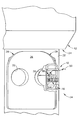
図1及び図2を参照すると、MRI装置12の磁気ボア24の外で、図1に示されている患者支持台22の上に患者20がうつ伏せに寝ている。患者の胸が胸部支持台28の上面26に支持されている。この上面24は、撮像及び治療のために患者の乳房を下垂させるための開口30及び開口32を有する。特に図2を参照すると、右の開口30が位置決め取付具16と共に示されている。この位置決め取付具16は、患者の右乳房を長手方向に固定及び圧迫するために内側圧迫プレート(図示せず)と協働するように横方向に配置されている。複数のアンテナ要素(図示せず)が、MRIボア24からの強い磁界によって誘導された乳房組織から発せられた高周波(RF)信号を検出するために開口30の周りに配置されている。胸部支持台28、位置決め取付具16、及びアンテナは、総称して乳房コイル34と呼ばれる。
【0028】
生検器具14は、プローブ組立体38に取り付けることができる生検ハンドル36を含む。位置決め取付具16は、プローブ組立体38の先端部40を特定の生検部位に配置する定位MRI誘導生検のためにプローブ組立体38を正確に配置する。この位置は、患者に対して水平方向及び長手方向であるX軸座標によって表される(図1及び図2の右から左の方向)。Z軸は垂直方向の高さと定義され、X軸とZ軸は、位置決め取付具16の横方向の圧迫プレート42上で交差する。横方向の圧迫プレート42は、内側圧迫プレート(図示せず)と協働して患者の乳房を固定及び圧迫する。この位置はまた、図1及び図2の上下方向として示される挿入の深さ即ちY軸についても表される。プローブ組立体取付装置44により、プローブ組立体38が生検器具14のプローブハウジング46に取り付けられている。
【0029】
この取付装置44は、プローブハウジング46、従ってプローブ組立体38を所望のX,Y,Z座標に合わせるための整合位置合わせガイド(詳細は後述)を含む。例えば、深さスライド48により、先端部40が開口30及び横方向の圧迫プレート42の先に突出するようにプローブ組立体38を配置できる。次に、選択されたX軸及びZ軸の座標を維持したまま、プローブ組立体38を深さスライド48によってY軸方向に移動させる。更に、取付装置44は、図2に示されているようにプローブ組立体38に取り付けられると、生検ハンドル36を支持して、プローブ組立体38の挿入の角度を維持する。プローブハウジング46により、麻酔薬などの流体を注入或いは排出するための真空内腔アクセス管50を介してプローブ組立体38の内部にアクセスできる。
【0030】
図3は、MRI磁気ボア24の狭い制限内に患者支持台22を挿入できるように、生検ハンドル36が取り外され深さスライド48が内側に移動したコア生検器具システム10を示す図である。更に、外科医は、たとえ閉鎖型磁気ボア24を用いたとしても、MRI装置12によって提供される定位座標の利点を十分に利用できる。具体的には、挿入する際にプローブ組立体38の映像がなくても、定位的に得られた座標を用いることができる。位置決め取付具16により、外科医が現在の深さを確認しながらプローブ組立体38を手動で挿入することができる。外科医は触覚フィードバックにより、接触している組織の密度及び硬さを正確に知ることができる。更に、挿入後も、プローブ組立体38が正確な位置に保持されるため、このプローブ組立体38により、その他の診断及び治療器具、並びに流体処置のためのアクセスが提供される。
【0031】
代替或いはそれに加えて、Y軸調節機構を位置決め取付具16に組み込むことができ、これにより機械的な優位性が得られ、プローブ組立体38を制御して意図するように挿入することができる。更に、Y軸調整機構は、所望の生検位置に配置した後、プローブ組立体38を逆方向に移動しないようにするための摩擦、ラチェット、または固定機構を含み得る。このようなY軸調節の例として、限定するものではないが、プローブ組立体取付装置150と位置決め支持フレーム126との間を歯車伝達するサムホイールがあげられる。
【0032】
図4は、プローブハウジング46、続いてプローブ組立体38を取り付けることができる生検ハンドル36を含む生検器具14を示す図である。プローブ組立体38は、基端部に中心カッター開口54を備えたオス型円筒係合部分52を含む。このカッター開口54は、細長いニードル58の長手方向のカッター内腔56と整合している。カッター内腔56は、ニードル58の先端部におけるニードル先端62に近接した横方向に設けられたサンプルポート60と連通している。このニードル先端62は、患者の軟組織に突き刺すために用いられる。ニードル先端62は尖っていて、ULTEMやVECTRA等のMRI適合性樹脂から形成されるのが好ましい。例示されている実施形態では、ニードル先端62は3つのピラミッド型の刃を含むが、別の形状及び/または挿入部を含む構造であっても良い。更に、上記した同時係属出願第10/021,407号(名称、「アーチファクトを残した先端部を備えたMRI適合性生検装置(AN MRI COMPATIBLE BIOPSY DEVICE HAVING A TIP WHICH LEAVES AN ARTIFACT)」)に記載されているように、例示目的の実施形態は、邪魔にならない小さなアーチファクトをMRIスキャン上に示す材料を含むという利点を有する。
【0033】
図5は、プローブを組織内に挿入する際の力を低減する尖った刃65を受容するためのX型スロット63を先端側に備えた円錐形のニードル先端62’を示す図である。刃65は、チタン、ステンレス鋼、ニチノール、アルミニウム、Elgiloy(登録商標)、及びセラミック等から形成することができる。図示したような2つの刃の表面が交わるのではなく、先端側の1つのスロットに1つの尖った刃の表面が設けられるなど、別の鋭利な刃65の形状を用いても良いことを理解されたい。
【0034】
挿入中にサンプルポート60をブロックするために、切断部材即ちオブトラトールスタイレットをカッター内腔56内に前進させることを理解されたい。ニードル58が一旦配置されたら、サンプルポート60を露出させ、その中に組織を引き入れることができる。具体的には、ニードル58の長手方向の長さに沿ってオス型円筒係合部分52に連通した真空チャンバー内腔64を介して、サンプルポート60に近接したカッター内腔56内のサンプルボウルを真空引きする。具体的には、一連の小さな孔により、サンプルポート60から真空チャンバー内腔64内に気体や液体は進入し得るが、組織サンプルは進入できないようになっている。
【0035】
円筒係合部分52の周りのリング66が、プローブハウジング46のメス型円筒係合部分68の内面と嵌合し密封される。リング間で、基端側真空ポート(図4には示されていない)とプローブハウジング46の真空経路(図示せず)とが連通している。係合部分52と係合部分68との間の係合により、ニードル58の基端部に近接して設けられたサムホイール70と共にニードル58が回転できる。リング66に設けられた円形の開口により、ニードル58の回転角度に関係なくプローブハウジング46の真空経路と真空チャンバー内腔64との連通が維持される。従って、サンプルポート60が、ニードル58の先端部の周りの全ての方向における組織に接触できる。真空の利用により、生検サンプリングの際に体積の大きい組織をサンプルボウルの中に選択的に引き込むことができる。
【0036】
プローブハウジング46には、位置決め取付具16に取り付けるための取り付けプロング72が横方向に設けられている。更にプローブハウジング46は、生検ハンドル36のフランジ78に対して長手方向に整合する基端側を向いた立方体様係合部材74を備えている。この立方体様係合部材74は、垂直及び水平方向の溝76を備えている。プローブハウジング46はまた、タブ80及びタブ82のそれぞれに取り付けられた反対方向を向いた一対の凹状グリップ84及びグリップ86を利用して、生検ハンドル36の先端側係合端部のかぎ状の固定タブ80及び82を受容して生検ハンドル36を選択的に固定したり、解放して取り外したりできる。生検ハンドル36は、詳細を後述するように、カッター内の経路を介した真空引きによりカッター内腔52から引き込まれたあらゆる組織サンプルを取り出すためのサンプルウインドウ88を含む。
【0037】
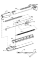
図6は、カッター内腔56内でカッター90を平行移動及び回転させるための手段を含む分解された生検ハンドル36を示す図である。電源コード18を介して2つの回転機構用電源が生検ハンドル36の基端部に接続されているため、横方向の動きと回転方向の動きを別々に達成することができる。これらの2つの回転機構用電源は、ねじで互いに固定される取り外し可能なシェル94と下側のシェル96との間に画定された配線用開口92からハンドル36内に延びている。取り外し可能なシェル94は、電源コード18をハンドル36に接続する際に取り外される。下側ギアハウジング98は下側シェル96に支持されており、上側シェル100と協働して、細長い駆動ねじ102、細長い軸方向のねじ104、及びカッターキャリッジ106の動きを制限している。具体的には、ねじ102及びねじ104は共に回転可能であり、互いに平行に配置されていると共にカッター内腔56の長手方向の軸に平行に配置されている。それぞれのねじ102及びねじ104は、電源コード18からのそれぞれの電力により駆動される。駆動ねじ102は、キャリッジ106に挿入され、その対応するリッジと相互作用して、駆動ねじ102の回転の方向及び速度に応じてキャリッジ106が長手方向に移動する。
【0038】
或る適用例では、2つの独立した回転機構用電源の代わりに1つの回転用電源を用いても良い。生検ハンドル36における伝達機構により、1つの回転用電源を平行移動と回転運動の2つの動きに変換することが可能である。更に別の適用例では、1つの回転用電源が、直接平行移動及び回転運動の両方に供給される。このような平行移動及び回転用の電源ケーブルをカッター90に接続してその動きを直接制御することができる。
【0039】
カッター90は、カッター内腔56の先端部内の組織を切断するための鋭利な先端部を備えた細長いチューブである。カッター90の基端部には、軸方向の回転のために軸ねじ104と噛合するカッターギア108が設けられている。このカッターギア108は、キャリッジ106のギアウインドウ110によって露出されている。チューブ状の組織リムーバー111が、カッター90の基端部から挿入され、長手軸と整合するように配置されている。組織リムーバー111は、サンプルウインドウ88まで延びており、制御モジュールによって選択的に真空引きされる。従って、カッター90が引き戻されると、組織リムーバー111の真空引きにより、カッター90の先端部の試料がサンプルウインドウ88まで吸引され、吸引された試料が組織リムーバー111と接触し、その試料が生検器具14から取り出される。
【0040】
キャリッジ106は先端側に突き出たガイド112及びガイド114を含み、これにより生検ハンドル36とプローブハウジング46との間の遊びをなくすと共にカッター90の平行移動の深さを外科医に示す。ハンドル36及びハウジング46の組み立てられた部品間の遊びをなくすことにより、ニードル58の先端部のデッドゾーン長さを最小にできる。カッター90は、試料を確実に切除するためにサンプルポート60を完全に通過すべきである。完全に切除するために、カッター90は、組立体として可能な最大距離移動すべきである。係合する部材間の製造誤差にバラつきがある場合は、過度に移動できるようにサンプルポート60の先端側のカッター内腔56の距離を長くするべきである。ニードル先端62を理想的な位置よりも更に先に進めて、重要な組織付近へのサンプルポート60の配置を防止しなければならない場合もある。完全或いはほぼ完全に移動すると、ガイド112及びガイド114がプローブハウジング46と接触し、ハウジング46が最も先端側に移動する。従って集合誤差を最小にするために臨界次元を求めるのが簡単になる。
【0041】
図6はまた、位置決め取付具16の一形態で用いられるブレース116及びブレースアーム118を示す図である。ブレース116及びブレースアーム118は、ハンドル36の重量を支持し、整合を維持するために用いられる。従って、プローブ組立体38に荷重がかかるような撓みがこの組立体に生じないため、ニードル58が目的の生検部位から不所望に移動してしまうことがない。
【0042】
図7及び図8は、図4のニードル58を示す図である。これについての詳細は、名称が「MRI適合性外科生検装置(AN MRI COMPATIBLE SURGICAL BIOPSY DEVICE)」である前記出願に示されている。具体的には、細長いニードル58が、長手方向の軸の両側にある左側本体部材120と右側本体部材121とから形成されている。半部分120及び半部分121の縁を部分注入し易いようにゲート型であり、それらの縁がリッジを備えた段になっているため、容易に2つの半部分120,121を互いに組み付けることができる。2つの半部分120,121は互いに接着される。カッター90に平滑な表面を提供するカッターチューブライナー122が2つの半部分120,121の間に挿入され、特に組み立て中にカッター内腔56への接着剤の流入を防止することができる。
【0043】
図9は、前進したカッター90がウインドウ88を通り、ハンドル36とプローブハウジング46とが係合した拡大図を示す。更に、ガイド112及びガイド114がプローブハウジング46と殆ど接触するように前進し、カッター90の先端部がその最も先端側に位置している。全ての許容差が取り除かれた極値或いはその近傍で、ガイド112及びガイド114がプローブハウジング46に接触する。外科医は、ガイド112及びガイド114の側面の目盛りを見てカッターの位置を知ることができる。更に、プローブハウジング46内に挿入されたかぎ状の固定タブ80及び固定タブ82と、ニードル80を回転するために用いられるサムホイール70と、排気する或いはその他の方法で真空内腔60にアクセスするために用いられる真空内腔アクセス管50とが詳細に示されている。
【0044】
図9〜図11は、それぞれ内側に突出した部材124及び部材125を備えたグリップ84及びグリップ86を示す図である。カッター90が先端方向に前進すると、この部材124及び部材125がそれぞれ、ガイド112及びガイド114に接触し、ハンドル36が外れないようになる。図10では、カッター90が引き戻されているため、グリップ84及びグリップ86を内側に押して、プローブハウジング46からかぎ状の固定タブ80及び固定タブ82を取り外すことができる。図11では、カッターキャリッジ106が前進して、ガイド112及びガイド114がプローブハウジング46に接触しているため、かぎ状の固定タブ80,86とプローブハウジング46との間の全ての長手方向の隙間がなくなっている。
【0045】
図12〜図15は、プローブ組立体38を正確に位置決めし、生検ハンドル36を支持するための手段を含む位置決め取付具16を示す図である。具体的には、位置決め支持フレーム126が、ガセット130及びガセット132により互いに側部が固定された垂直なスライドプレート128とそれと直交する圧迫プレート42から構成されている。ロッド134及びロッド136が、圧迫プレートを貫通して患者の乳房を圧迫するために内側圧迫プレート(図示せず)に調節可能に取り付けられている。圧迫プレート42に設けられた平行なスロット138の列として示されている開口により、所望の生検部位にアクセスすることができる一方で、患者の乳房に十分に接触できるように圧迫プレート42構造が十分に保たれている。別法では、開口は、垂直方向に整合し、かつ垂直方向に平行なスロットの列に整合した一連の孔、或いは他の形状の大きな開口であってもよい。更なる別法では、圧迫プレート42の一部を、必要に応じて孔を形成することができるように透過性としてもよい。
【0046】
所望の生検部位は、小さなアーチファクトを生成する基準マーカー140を見てMRIスキャン中に定位的に決めることができる。基準マーカー140は、圧迫プレート42の都合の良い位置に配置可能な基準マーカーホルダー142内に受容される。この基準マーカーホルダー142は、スロット138に沿って設けられた凹部に正確に配置される。別法では、基準マーカーは、圧迫プレート42に埋め込む即ち固定しても良い。
【0047】
位置決め支持フレーム126は、プローブ組立体38を位置合わせするためのガイドを提供する。スロット138及び圧迫プレート42についてのX,Y,Z軸が決定される。具体的には、垂直方向即ちZ軸と水平方向即ちX軸が、圧迫プレート42の表面によって決まる。深さ方向即ちY軸は、圧迫プレート42の面からの距離として決定される。水平スライドプレート128は、X座標をセットするために横方向に整合した前レール144及び後レール146を含む。前レール144に沿って設けられた水平方向の目盛り148により、プローブ組立体取付装置150の正確な位置を外科医が知ることができる。
【0048】
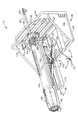
第1の形態の取付装置150は、プローブ組立体38を固定するために1つの垂直ペデスタル152を用いている。更に、生検ハンドル36は、その基端側底部がハンドル支持ロッド156に接続されたブレース116によって支持されている。ハンドル支持ロッド156は、垂直ペデスタル152の一側のロッド孔158に挿通されている。ブレース116の適切な高さは、ハンドルの下側に沿って整列された一連のスロットのどのスロットを選択するかによって決まり、ブレース116がブレースアーム118に対して移動する。ブレースアーム118の第1の端部は、ブレース116の中間のスロット162内にスライド可能に取り付けられており、その第2の端部はハンドル36の先端部に取り付けられている。
【0049】
図12に示されているようにプローブ組立体38からハンドル36が取り外され、オブトラトールスタイレット164がカッター内腔56内に挿入され、カッターポート88が閉じられている。このスタイレット164は、真空内腔チャンバー64とカッター内腔56との間の連通を維持するべくその先端部近傍の径方向を向いた貫通孔を有するようにできる。別法では、スタイレット164を部分的に引き抜いて、カッターポート88と管50とが連通するようにできる。
【0050】
スライド166には、サイドプレート128のレール144及びレール146上を水平方向にスライドできるように底面に溝が設けられている。スライド166はまた、ペデスタル152のY軸方向のスライドを案内するために、Y軸方向に設けられた中央の溝168を含む。スライド166に整合して回動可能に取り付けられた回動可能な深さスライド170により、ペデスタル152が深さ方向に十分な範囲移動することができる。深さスライド170が水平方向に最も低い位置では、ペデステタル152は、プローブ組立体38が圧迫プレート42から外側に離れる方向に十分にスライド可能である。ペデスタル152がスライド166上を先端方向にスライドした位置では、深さスライド170を上方に回動させたり、或いはその他の方法で取り外すこともできる。中央の溝168に沿った深さ目盛り172により、外科医がプローブ組立体38の挿入深さを知ることができる。
【0051】
ペデスタル152上の垂直目盛り176を読みながら、垂直スライド174をペデスタル152上をスライドさせて、Z軸に沿って垂直方向の位置を合わせすることができる。垂直スライド174の両側面の孔178の一方の孔178から取付プローブ72を挿入して、プローブハウジング46を取り付けることができる。
【0052】
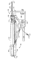
図16及び図17は、第2の形態の取付装置150を示す図である。この取付装置150は、ブレース組立体の代わりに第2の垂直ペデスタル180を用いてハンドル36を支持している。また、プローブハウジング46は、第1の垂直ペデスタル152の向かい側に取り付けられている。第2の垂直ペデスタル180の第2の垂直スライド181を、図17に示されているように第1の垂直スライド174と接触させることができるため、両方の高さの設定が一度にできる。垂直スライド174及び垂直スライド181はそれぞれ、垂直ペデスタル152及び垂直ペデスタル180に対してラチェット式に動くようになっているため、図16に示されているように互いに分離されても位置が維持される。更に、2つの垂直ペデスタル152及び垂直ペデスタル180が互いに密着する入れ子状になっているため、閉鎖型MRI磁気ボア24の閉じた領域内で用いられる場合、位置決め取付具16の基端方向への変位を最小に抑えることができる。第2の垂直スライド181が、プローブ組立体38と同じX軸水平方向に正確にハンドル36を整合できるように、ハンドル36の底面と係合する成形領域を含むことに留意されたい。
【0053】
図18及び図19は、第3の形態の取付装置150を示す図である。この取付装置150では、スライド166及びペデスタル152の代わりに、スライドプレート128上を水平方向に動かすための第1のスライド184を備えた交差テーブル組立体182が用いられている。深さスライド186は、第1のスライド182の上部溝内に受容されている。図19を参照すると、ねじ192で互いに押されて一対の交差ブレース190が延び、深さスライド186が第1のスライド184に対して上昇する。第3の形態の取付装置150は、2つの垂直調節器具、並びにハンドル36及びプローブ組立体38のそれぞれのために別々に取付具を用いなくとも、取り外し可能なプローブ組立体38及び生検ハンドル36の両方を目的の高さに支持できるという利点があることに留意されたい。
【0054】
図20は、閉鎖型MRIであってもコア生検を正確かつ迅速に行うことができるMRI誘導乳房コア生検を行うための一連の動作即ち方法200を示す図である。更に、MRIからの定位的な位置情報を最大限利用して、生検プローブの先端部を連続的に映像化する必要なく、MRI適合性コア生検プローブを位置合わせするための方法である。
【0055】
臨床的な乳房生検を実行する前に、装置が適切に機能するように装置の初期化を行う。従って、まずブロック202で、ニードル、サムホイール、及びハウジングを含むプローブをハンドルに取り付ける。組み立てた生検器具を、電源コードを介して制御モジュールに接続し、そのシステムに電力を供給し、制御モジュールの論理回路を起動する(ブロック204)。回転速度及び移動距離についてのパラメーターを入力する。システムが、例えば60分停止していたと制御モジュールが判断すると、論理回路の初期化を実施する。従って、移動伝達系の初期化を実施し(ブロック206)、回転伝達系の初期化を実施し(ブロック208)、更に真空システムの初期化を実施する(ブロック210)。初期化が必要でない場合は、ブロック206〜ブロック210をバイパスする。
【0056】
次に、患者の乳房を位置決め機構に固定し(ブロック212)、患者をMRI磁気ボア内に入れる(ブロック214)。MRIスキャンを実行して、位置決め機構上の移動可能な基準マーカーに対する疑いのある組織の位置を定位的に求める(ブロック216)。開放型MRIの場合は必要ないが、閉鎖型MRI磁気ボアの場合は患者を磁気ボアの外に出す(ブロック218)。最小の侵襲性の真空を用いるコア生検の前に麻酔薬を投与する(ブロック220)。位置決め機構のX,Y,Z座標位置合わせ機能を用いて、その位置決め機構の位置合わせガイドを、所定の生検部位に挿入するために配置する(ブロック222)。
【0057】
必要に応じて、プローブ組立体38に取り付けられる挿入器具を用いて挿入を容易にすることもできる(ブロック224)。例えば、超音波切断先端(ultrasonic cutting tip)、エクステンダー、及び外部チューブから成る組立体をプローブ組立体38及びニードル先端62のスロット内に挿入するか、或いはサンプルポート60から出してニードル先端62にスナップ止めする。これは、ニードル58にスナップ止めされるように構成された超音波装置のハウジングで達成することができ、トロカールオブトラトールをトロカールカニューラ上にスナップ止めするのに類似している。次に、超音波先端を患者に挿入する前にエネルギーを加える。
【0058】
取付装置を深さ方向に引いた状態で、プローブ組立体を位置決め機構の指定されたXZ座標に取り付ける(ブロック226)。ブロック224で密閉されなかった場合は、カッター内腔にオブトラトールスタイレットを挿入して密閉する(ブロック228)。真空内腔は、同様に密閉するか(例えば、真空内腔アクセス管50に取り付けられる止め栓)、或いは挿入中に流体や組織を吸入するために用いる。次に、整合不良とならないように、位置決め機構を用いてY軸方向にプローブを進める(ブロック230)。適切に配置したら、ブロック224で挿入補助器具を取り付けた場合はその挿入補助器具をプローブ組立体のカッター内腔から引き戻して取り外す(ブロック232)。
【0059】
プローブを配置したら、プローブ組立体内に様々な流体を移送することができる(ブロック234)。例えば、サンプルポートが露出した状態で、真空内腔を介して真空引きし、生検部位に生じたあらゆる血腫或いは気泡を吸引する。麻酔薬やMRI造影剤等の治療剤を生検部位に直接注入することができる。患者を閉鎖型磁気ボアでスキャンする場合は、スキャンするために患者をボア内に戻す(ブロック236)。更に、試料を切除する前に、確認のために必要に応じて生検部位を真空引きしてサンプルポートのボウル内に疑いのある組織を吸引することもできる(ブロック238)。次に、MRIスキャンを実施して、プローブ組立体のボウルにおける組織の配置を確認し、必要であればプローブ組立体の位置を調整して再びスキャンを実施する(ブロック240)。
【0060】
制御モジュールによりサンプルモードを選択して、所定の設定に従ってカッターの平行移動及び回転の一連のステップを実行する。この時、真空を利用してサンプルを吸引し、サンプルウインドウの方にカッターと共に試料を引き戻す(ブロック244)。診断或いは治療目的のためにこの生検部位における試料が更に必要な場合は(ブロック246)、サムホイールを回転させて別の角度にサンプルポートを向け(ブロック248)、ブロック244に戻って再びサンプルモードを選択して一連のステップを実施する。
【0061】
コア生検を実施した後、更に挿入しないでも、プローブ組立体を用いて他の最小の侵襲性の診断及び治療を行うことができる。生検ハンドルが開放型MRI磁気ボア等に装着された場合は、このハンドルを取り外して、取り外し可能なプローブ組立体にアクセスできるようにする(ブロック250)。プローブ組立体内に挿入できる器具として、(1)ガンマ線検出器、(2)穿刺に必要な力を低減するためにエネルギーが加えられた穿刺用先端、(3)除去した組織の再形成を助ける挿入物(例えば、一面或いは二面のシェイバー挿入物(one or two sided shaver inserts))、(4)分光イメージング装置、(5)一般的な組織特徴付けセンサー(例えば、(a)マンモグラフィー、(b)超音波、断層撮影、造影剤、パワードップラー、(c)PET及びFDG([Flourine−18]‐2−デオキシ‐2‐フルオロ‐グルコース)、(d)MRIまたはNMR、乳房コイル、(e)機械的なインピーダンス或いは弾性率、(f)電気的なインピーダンス、(g)光波分光法、ラマン分光法、位相、偏光、波長/周波数、反射率、(h)レーザー誘導蛍光法或いは自動蛍光法、(i)放射線放出/検出、放射線シードの埋め込み、(j)フローサイトメトリ、(k)ゲノム化学、PCR(ポリメラーゼ連鎖反応)‐brca1、brca2、(l)プロテオミクス、タンパク質経路)、(6)組織マーカー検出装置、(7)MRI増強のための挿入物或いは装置、(8)スティックに設けられたバイオチップ、(9)内視鏡、(10)診断用薬物送達装置、(11)抗癌剤送達装置、(12)放射線治療送達装置、放射線シード、(13)成長因子及び/またはサイトカインの放出をブロックするための治療生検用の抗播種剤(例えば、クロルフェニラミン(CPA)は、播種された癌細胞の増殖を培養細胞において75%低減することが分かっているタンパク質である)、(14)蛍光標識された抗体、残っている癌細胞を検出するためにレーザー光源からの蛍光を刺激して蛍光信号を検出する結合光ファイバー(couple fiber optics)、(15)超音波映像化を助けるべく体腔内に流体を供給するため、体腔の形状を正常にするため、或いは出血を低減するべく膨張させるための正の圧力源、(16)生物学的標識の送達装置(例えば、(a)細胞増殖、新血管分布、ミトコンドリア密度、及び糖代謝の機能のイメージング、(b)エストロゲン受容体の免疫組織化学、her2neu、(c)ゲノム化学、PCR(ポリメラーゼ連鎖反応)‐brca1、brca2、(d)プロテオミクス、タンパク質経路)、及び(17)マーキングクリップが挙げられる。
【0062】
次の超音波、X線、またはMRIスキャンでその生検位置を識別できるように組織マーカーをプローブ組立体内に挿入し(ブロック252)、次にそのプローブを取り外す(ブロック254)。
【0063】
図21及び図22は、挿入する前にプローブ組立体38のニードル先端62を保護し、場合によってはプローブ組立体38の位置決めを容易にする先端プロテクター260を示す図である。更に、この先端プロテクター260は、臨床前の設定等(例えば、真空の漏れのテスト)に邪魔にならない。具体的には、先端プロテクター260は、サンプルポート60を塞がないニードル58上にクリップを備えた取付部材262を含む。先端プロテクターの先端部分は、半球状のディスク264として示される保護部材でニードル先端62を完全に覆うことができる。この保護部材は、患者に不快感を与えずに患者の乳房と接触するように配置できる。更に、ある適用例では、半球状ディスク264は、上記したようなMRIアーチファクト生成物質から成る、或いはそのような物質を含み得る。半球状ディスク264は、患者の乳房の外側からMRIでスキャンされるため、疑いの或る病変の邪魔にならず、そのアーチファクトの位置を迅速に求める助けとなる強力なアーチファクトが生成される。
【0064】
先端プロテクター260に組み込まれた新規の基準マーカーを用いるとことにより、挿入の前に疑いのある病変に最も近い挿入位置に基準マーカーを配置することを好む操作者のために、位置決めプロセスの1つのステップを減らすことができる。手順としては、先端プロテクター260を装着し、操作者がプローブ組立体38をペデスタル152に取り付け、そのプローブ組立体38を、初めの診断映像に基づいて、疑いのある組織があると思われる部位の近傍の乳房組織に向けて移動させる。次に、基準マーカーから病変までの距離を求める。この距離Δはプローブの現在の位置に基づいている。基準マーカーからボウルの中心までの距離を考えなければならないため、Y軸方向に一定の偏差がある。取付部材262により半球状ディスク264を正確に配置して、Y軸の偏差を推定できるようにする。これはより直観的である。なぜなら、Δ位置が、プローブの現在位置に依存するためである。
【0065】
本発明は幾つかの詳細な実施形態の説明により明らかにしてきたが、請求の範囲がそのような細部によって制限されるものではないことを理解されたい。当業者であれば、更なる利点及び改良が明らかであろう。例えば、取り外し可能なプローブ組立体は様々な利点を有するが、本発明の評価されるべき点は、単一体の生検器具であることである。例えば、診断及び治療用器具のためのカッター内腔へのアクセスは、カッター開口或いは類似の開口を介して実施可能である。
【0066】
別の例では、位置決め機構16は、下垂した患者の乳房を横方向に圧迫するように示されているが、本発明の態様では、別の方向の位置決め及び撮像のためにも用いることができる。
【0067】
更に別の例として、MRIが定位的にコア生検を誘導するための撮像手段として記載されたが、本発明のある態様では、他の撮像手段を用いることもできる。
【0068】
更なる例として、カーテシアン座標(X,Y,Z)位置合わせ法を開示してきたが、極座標法或いは球面座標法の全て或いはその一部を用いて、所定の角度で取り外し可能なプローブ組立体を挿入できることを理解されたい。
【0069】
更なる例として、腹臥乳房圧迫装置を示してきたが、本発明の応用例では、立位、側臥位、または仰臥を含む様々な位置で用いることができる医療用圧迫装置を用いても良い。更に、本発明の或る態様では、横方向の圧迫プレートの代わりに内側圧迫プレート或いは上部及び下部圧迫プレート対を用いて生検プローブを位置合わせしても良い。更に、本発明の或る態様では、現在用いられている或いは将来利用可能になる別の診断撮像手段を用いることもできる。更に、本発明の或る態様では、最小の侵襲性の方法で他の診断及び治療装置のためにプローブを位置合わせすることは勿論、体の他の部分における診断のための誘導生検にも用いることもできる。
【0070】
更なる例として、真空チャンバー内腔とカッター内腔との間に、細長いニードルを長手方向の構造的な障壁を設けずに形成しても良い。その代わりに、前進するカッター90が、細長いニードルの内部キャビティの非円形断面(例えば楕円形)内において円形断面を有するカッター内腔を画定するようにできる。更に、非円形ライナーを用いて、分かれていない内部キャビティ内に接着剤が進入するのを防止することもできる。
【0071】
本発明の実施態様は以下の通りである。
(A)定位生検法において生検プローブを位置合わせするために医療用圧迫装置に用いられる位置決め装置であって、
複数の開口を有するプレートと、
前記生検プローブを受容し、係合するように構成され、かつ前記プレートに対して前記生検プローブを合わせるための整合位置決めガイドを含む取付装置と、
生検器具の基端部を支持するように構成され、かつプローブハウジングに係合可能な先端部を有する生検器具支持体とを含むことを特徴とする位置決め装置。
(1)磁気共鳴映像にアーチファクトを生成する基準マーカーを更に含み、この標的を前記プレートに取り付けできることを特徴とする実施態様(A)に記載の位置決め装置。
(2)前記取付装置が、水平方向のガイド、垂直方向のガイド、及び深さ方向のガイドを含むことを特徴とする実施態様(A)に記載の位置決め装置。
(3)前記取付装置が、前記プレートに対して水平方向或いは深さ方向の内の第1の方向にスライド可能とするように構成されたスライドプレートと、前記スライドプレート上において前記第1の方向に移動する第1のスライドとを含むことを特徴とする実施態様(A)に記載の位置決め装置。
(4)前記第1のスライドが、前記プレートに対して水平方向及び深さ方向の内の前記第1の方向ではない第2の方向にスライドできるようにするガイドを含み、前記取付装置が更に、前記第1のスライドによってガイドされて前記第2の方向に移動する第2のスライドを含むことを特徴とする実施態様(3)に記載の位置決め装置。
(5)前記垂直方向のガイドが、ペデスタルと、前記ペデスタルに対して垂直方向に動きが限定されたプローブハウジング取付具とを含み、前記ペデスタルが、前記水平方向のガイド及び前記深さ方向のガイドによって前記プレートに対して水平方向及び深さ方向に選択的に移動可能であることを特徴とする実施態様(2)に記載の位置決め装置。
【0072】
(6)前記生検器具支持体が、前記生検器具支持体の基端部から前記ペデスタルにかかる荷重を支持するように構成されたブレースを含むことを特徴とする実施態様(5)に記載された位置決め装置。
(7)前記生検器具支持体が、前記第1のペデスタルに対して基端側に位置して前記第1のペデスタルと共に水平方向及び深さ方向に移動するように構成された第2のペデスタルを含むことを特徴とする実施態様(5)に記載の位置決め装置。
(8)前記垂直方向のガイドが、前記水平方向のガイド及び前記深さ方向のガイドに対して前記水平方向及び前記深さ方向に選択的に移動可能であって選択的に垂直方向に伸長できるように構成された垂直交差機構を含むことを特徴とする実施態様(2)に記載の位置決め装置。
(9)前記深さ方向のガイドが、基端側深さスライドと先端側深さスライドとを含み、前記基端側深さスライドが、外側への突出を小さくするために前記先端側深さスライドに対して選択的に移動可能であることを特徴とする実施態様(A)に記載の位置決め装置。
(10)前記基端側深さスライドが、外側への突出を小さくするために前記先端側深さスライドに対して選択的に回動可能であることを特徴とする実施態様(9)に記載の位置決め装置。
【0073】
(11)Y軸方向の前記深さガイドに機械的優位性を付与するように構成されたY軸整合機構を含むことを特徴とする実施態様(A)に記載の位置決め装置。
(B)磁気共鳴イメージング(MRI)誘導コア生検において生検プローブを位置決めするために医療用圧迫装置に用いられる位置決め装置であって、
MRI適合性材料から形成され、かつ複数の開口を有する圧迫プレートと
MRI適合性材料から形成され、かつ前記生検プローブを係合し、受容するように構成され、更に前記プレートに対して前記生検プローブの向きを合わせるための整合位置決めガイドを含む取付装置と
前記圧迫プレートに取り付けられ、かつMRIスキャンにおいてアーチファクトを生成する基準マーカーとを含むことを特徴とする位置決め装置。
(12)更に、前記基準マーカーを受容するように構成された基準マーカーホルダーを含み、前記基準マーカーホルダーを、前記圧迫プレートの前記複数の開口と係合するように取り付けできることを特徴とする実施態様(B)に記載の位置決め装置。
(13)前記圧迫プレートが、前記基準マーカーを保持するための基準マーカー凹部を含むことを特徴とする実施態様(B)に記載の位置決め装置。
(C)腹臥位診断イメージング誘導生検のための乳房圧迫組立体であって、
患者の乳房が下垂できるようにするための開口を含む胸部支持体と、
前記胸部支持体に接続された内側圧迫プレートと、
前記患者の乳房を固定するために前記内側圧迫プレートの対向側に位置し、前記内側圧迫プレートから選択した距離離間した、前記胸部支持体に接続された側面圧迫プレートと
前記側面圧迫プレートに直交するように接続されたスライド部材と、
前記スライド部材に支持され、プローブを空間的に案内して位置決めするように構成されたプローブ位置決め装置とを含むことを特徴とする乳房圧迫組立体。
(14)前記プローブ位置決め装置が、第1及び第2の直交するガイドで前記プローブを空間的に案内して配置するように構成され、前記第1及び前記第2の直交するガイドにより、側面圧迫プレートにおける所望の挿入点に前記プローブを配置でき、前記挿入点に対して所定の挿入角に前記プローブを固定することを特徴とする実施態様(C)に記載の乳房圧迫組立体。
(15)更に、前記プローブ位置決め装置が、生検位置に前記プローブを挿入するために前記所定の挿入角に沿って前記プローブを案内する深さ位置決めガイドを含むことを特徴とする実施態様(14)に記載の乳房圧迫組立体。
【0074】
(16)前記深さ位置決めガイドを、プローブ挿入前の展開した状態に展開したり、プローブ挿入後の引き込んだ状態に引き込めることができ、これにより診断装置内に前記乳房圧迫組立体を入れることができることを特徴とする実施態様(14)に記載の乳房圧迫組立体。
(17)前記プローブ位置決め装置が更に、プローブ取付手段と、プローブ位置決め手段と、プローブ位置表示手段とを含むことを特徴とする実施態様(C)に記載の乳房圧迫組立体。
【0075】
【発明の効果】
MRI誘導生検装置を正確に配置するための装置であって、更なる侵襲性の処置を必要とすることなく生検部位の別の診断及び治療処置を行えるようにする、該装置が提供される。
【図面の簡単な説明】
【図1】MRI装置の領域外において使用状態にある生検器具、取付具、MRI乳房コイル装置、及び患者支持台の平面図である。
【図2】MRI装置内に挿入するように構成された使用状態にある生検器具、位置決め取付具、部分的に内部が見えるMRI乳房コイル装置、患者支持台の平面図である。
【図3】MRI装置内に挿入するように構成された使用状態にある、位置決め取付具、部分的に内部が見えるMRI乳房コイル装置、患者支持台、位置決め取付具に取り付けられ、生検ハンドルが取り外された生検器具の平面図である。
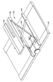
【図4】生検器具ハンドル、プローブハウジング、及びプローブに分解された生検器具の等角図である。
【図5】代替の生検器具のニードル先端部の詳細な正面等角図である。
【図6】生検器具ハンドルの組立分解等角図である。
【図7】図4の生検器具のプローブの組立分解等角図である。
【図8】図4の線7−7に沿って見た図4の生検器具のプローブの断面図である。
【図9】カッターの先端部の位置を示す視認できる部材を例示する、ハンドルとプローブハウジングとの境界部の拡大等角図である。
【図10】カッターが引き戻されて取り外された状態を例示する、ハンドル、プローブハウジング、及び組立体の先端部分の部分断面図である。
【図11】カッターが前進して移動できる空間がなくなり、固定タブが外れなくなった状態を例示する、ハンドル、プローブハウジング、及び組立体の先端部分の部分断面図である。
【図12】ハンドル部分がタワー/ブラケット位置決め取付具及びプローブ組立体から取り外された生検器具の等角図である。
【図13】図12のタワー/ブラケット位置決め取付具に取り付けられた生検器具の等角図である。
【図14】生検器具の位置決め取付具がタワー/ブラケット位置決めの形態である位置決め取付具及びプローブ組立体の組立分解等角図である。
【図15】生検器具のハンドル及びプローブ組立体を安定させるためのタワー/ブラケット支持体を例示し、生検器具の部分的に断面を示す側面図である。
【図16】位置決め取付具が2つのタワー支持体の形態であり、真空管及びオブトラトールスタイレットで2つの内腔が閉止された、取り外し可能なプローブ組立体を配置するための取付具の側面図である。
【図17】2つのタワー位置決め取付具に取り付けられた生検器具の等角図である。
【図18】生検器具を垂直方向に合わせるために、交差支持体を伸長させるための位置決め取付具のスライドプレートであって、交差支持体が折り畳まれた状態を示す等角図である。
【図19】生検器具を垂直方向に合わせるために、交差支持体を伸長させるための位置決め取付具のスライドプレートであって、交差支持体が伸長した状態を示す等角図である。
【図20】開放型及び閉鎖型MRIの両方で、図1の取り外し可能なMRI誘導生検器具を用いた一連の生検実施方法を示す流れ図である。
【図21】図12の取り外し可能なプローブ組立体のニードル先端に取り付けられた先端プロテクターの等角図である。
【図22】図21の先端プロテクターの細部を示す等角図である。
【符号の説明】
10 コア生検器具システム
12 閉鎖型MRI装置
14 MRI適合性生検器具
16 位置決め取付具
18 電源コード
22 患者支持台
24 磁気ボア
28 胸部支持台
30 開口
34 乳房コイル
38 プローブ組立体
40 プローブ組立体の先端部
42 圧迫プレート
44 プローブ組立体取付装置
48 深さスライド
50 真空内腔アクセス管
52 オス型円筒係合部分
54 カッター開口
56 カッター内腔
58 ニードル
60 サンプルポート
62 ニードル先端
64 真空チャンバー内腔
65 刃
70 サムホイール
72 プロング
74 立方体様係合部材
76 溝
78 フランジ
80,82 タブ
84,86 グリップ
88 サンプルウインドウ
90 カッター
92 配線用開口
94 取り外し可能なシェル
96 下側シェル
98 ギアハウジング
100 上側シェル
102 駆動ねじ
104 軸方向のねじ
106 キャリッジ
108 カッターギア
110 ギアウインドウ
111 組織リムーバー
112,114 ガイド
116 ブレース
118 ブレースアーム
120 左側本体部材
121 右側本体部材
122 カッターチューブライナー
124,125 突出部材
126 支持フレーム
130,132 ガセット
138 スロット
152 ペデスタル
156 支持ロッド
162 スロット
166 スライド
168 溝
170 深さスライド
172 深さ目盛り
174 垂直スライド
176 垂直目盛り
178 孔
180 第2の垂直ペデスタル
181 垂直スライド
182 交差テーブル組立体
184 第1のスライド
186 深さスライド
190 交差ブレース
260 先端プロテクター
262 取付部材
264 半球状ディスク[0001]
BACKGROUND OF THE INVENTION
Cross-reference for related applications
This application claims the benefit of US Provisional Patent Application No. 60 / 374,728, filed April 23, 2002, whose title is the same as the present application. This application is filed on the same day, and Hibner's name is “AN MRI COMPATIBLE BIOPSY DEVICE WITH DETACHABLE PROBE” and “Minimally invasive in MRI device” Related to their respective co-pending applications, which are "METHOD FOR PERFORMING MINIMALLY INVASIVE BIOPSY IN AN MRI MACHINE". The contents of all of which are hereby incorporated herein by reference.
[0002]
The present invention relates to an apparatus for sampling tissue, and more particularly to positioning a biopsy probe relative to a magnetic resonance imaging (MRI) breast coil to perform a percutaneous biopsy and to remove a lesion. Relates to an improved apparatus.
[0003]
[Prior art]
Diagnosis and treatment of patients with cancerous tumors, precancerous conditions, and other abnormalities is an area that has been studied extensively for many years. Non-invasive methods for examining tissue include palpation, thermography, positron emission tomography (PET), single photon emission computed tomography (SPECT). , Nuclear imaging, X-ray, MRI, CT, and ultrasound imaging. If the doctor suspects that the tissue contains cancerous cells, a biopsy is performed either by an incision or percutaneous method. In the case of an incisional biopsy, the surgeon makes a large incision with tissue using a scalpel so that the target tissue mass is directly visible and accessible. Next, the entire mass (resected biopsy) or part of the mass (incision biopsy) is removed. In the case of a percutaneous biopsy, a needle-like instrument is used to pass through a minute cut to reach the target tissue mass, and the tissue is collected for later examination and analysis. Percutaneous methods have many significant advantages over incision methods. For example, patients need less time to recover, less pain, less surgery time, lower cost, less risk of damaging nearby tissues, such as nerves, and no changes to the patient's body structure Etc. When a transcutaneous method is used together with an imaging device such as an X-ray or an ultrasonic wave, highly reliable diagnosis and treatment can be performed.
[0004]
There are two main methods for percutaneously collecting a part of the body tissue: a suction method and a core sampling method. With tissue aspiration using a fine needle, the tissue must be fragmented sufficiently small to be drawn into the liquid medium. Although this method is less invasive than other known sampling methods, it can test cells in the fluid (cytological test), but it can test cells and structures (pathological test). Can not do. In core sampling, tissue cores or fragments are collected by freezing or paraffin cutting for tissue examination and genetic examination. The type of biopsy used is largely determined by various factors present in the patient, and there is no ideal method in all cases. However, doctors often use core biopsies.
[0005]
In recent years, core biopsy devices have been used with imaging techniques to improve lesion targets. Many such devices are sold. One such product is MAMMOTOME (TM) sold by Ethicon End-Surgery, Inc. An embodiment of such an apparatus is disclosed in Patent Document 1, and the contents thereof are hereby incorporated by reference.
[0006]
As is apparent from Patent Document 1, this instrument is a kind of transcutaneous core / breast biopsy instrument utilizing image guidance. The instrument utilizes a vacuum and several steps for collecting tissue samples are automated. The doctor uses this device to actively capture the tissue using a vacuum before excising the tissue from the body. Thereby, tissues with various hardnesses can be sampled. With this device, multiple samples can be taken at various positions around its long axis without removing the device from the body. These features allow sufficient sampling of large lesions and complete removal of small tissue.
[0007]
Co-pending application 09 / 825,899, filed on April 2, 1997, which is incorporated herein by reference, includes additional features and promise of an apparatus that includes a molded tissue cassette housing. Various improvements are described. With this cassette housing, it is possible to operate and visually recognize a plurality of tissue samples without physical contact with the operator. Further, by connecting the housing and the piercing needle to each other using a thumb wheel, the needle can be rotated with respect to the housing, and the vacuum tube is prevented from being wound around the housing. During use, the thumbwheel can be rotated to rotate the device within the lesion and samples can be taken at various points within the lesion.
[0008]
When a breast biopsy is actually performed in the clinic, the instrument (probe and driver assembly) is fixed to the three-axis positioning head of the X-ray imaging apparatus. The triaxial-positioning head is located between the X-ray source and the image plate. The X-ray apparatus is equipped with a computer system. This computer system requires two x-ray images of the breast taken with x-ray sources at two different locations to determine the x-, y-, and z-axis coordinates of the suspected abnormal site. To do. In order to take a stereo X-ray image, the X-ray source must be able to move freely. Thus, an x-ray source is usually attached to the end of the arm opposite the x-ray source. This arm is pivotally attached to the frame of the device in the area of the imaging plate.
[0009]
In recent years, there has been a demand for handheld core sampling biopsy devices. This request was satisfied by Patent Document 2 whose contents are incorporated herein by reference. This patent document 2 discloses a handheld MAMMOTOME (trademark). The MAMMOTOME ™ is held generally parallel to the patient's chest wall and is not the arm to extract tissue parts closer to the chest wall than when using the instrument attached to the electromechanical arm. Operated by hand. Therefore, the operator can freely operate the tip of the MAMMOTOME ™ handpiece with respect to the target tissue mass. Furthermore, the handheld MAMMOTOME ™ captures a tissue portion closer to the chest wall than when harvesting using a device whose handpiece is held generally parallel to the patient's chest wall and attached to an electromechanical arm. Ideal because it can.
[0010]
In recent years, there is a desire to use the above-described biopsy apparatus together with an MRI imaging apparatus instead of an X-ray imaging apparatus. However, existing medical biopsy sampling devices use mass-produced probes that are made of mostly metal and have a plurality of small lumens. Accurate diagnosis with minimal invasiveness of a suspected breast lesion depends on the size of the sample taken and the precise positioning of the sampling device.
[0011]
These probes have many disadvantages due to their metallic nature. Normally, these metal probes are magnetically weak because they are conductive, which is an obstacle to use with MRI. Conductive and magnetically weak metal probes often cause magnetic field distortions in the image called artifacts. Since the lesion image includes a metal probe, it interferes with the lesion image, which is a problem.
[0012]
Since the conventional biopsy needle has a small sampling size, there is a limitation that the treatment time becomes long. Contrast agents tend to “wash off” suspicious lesions. That is, it rapidly spreads to the surrounding non-malignant breast parenchyma, and a suspicious lesion cannot be distinguished from the breast parenchyma within a few minutes. This limits the number of samples that can be collected using a conventional spring loaded core biopsy needle under direct image guidance.
[0013]
A further problem that often occurs during core needle biopsy is that hematoma is generated at the biopsy site during biopsy. Increased hematoma can be a problem during MRI-guided biopsy because the contrast agent circulating through the hematoma mimics a suspected lesion. Further, increased air at the biopsy site may cause susceptibility artifacts that may interfere with fat suppression MRI techniques in the biopsy site cavity.
[0014]
Because of these limitations of conventional biopsy needles, investigators need to make sure that the MRI-guided biopsy device is present in a suspected target (rather than in close proximity) with a lesion diameter of at least We concluded that it should be 1 cm or more. However, the desire for minimally invasive MRI-guided core biopsy is very much for small lesions. This is because small lesions are common, it is difficult to identify small lesions by MRI alone, and the prognosis is best when they are found to be malignant.
[0015]
Therefore, in order to eliminate the artifacts, there is a demand for a biopsy needle of the kind described above and entirely non-metallic (particularly non-ferromagnetic). Such a request was made by Huitema et al. Filed on December 12, 2001 (Application number is undecided) (Name: “AN MRI COMPATIBLE SURGICAL BIOPSY DEVICE”) Filled by. All of which are hereby incorporated by reference with reference to this patent application. This disclosed handheld biopsy device is free of unwanted artifacts and allows for precise placement of the probe. In addition, the disclosed vacuum can be used to avoid problems associated with hematomas or air cavities, as well as to visualize lesions entering the probe bowl and to ensure accurate probe placement. . Furthermore, since the volume of the probe and the opened cutting bowl can be quickly rotated, a plurality of samples can be collected continuously without removing the probe. Therefore, the biopsy time can be shortened.
[0016]
However, there is also a problem in completely eliminating the artifacts generated by the metal probe. This is because doctors rely heavily on certain artifacts that indicate where the tip of the probe is relative to the lesion. These requests are discussed in Rhad et al., Filed Dec. 12, 2001, in self-pending application No. 10 / 021,407 (named “MRI-compatible biopsy device with an articulated tip (AN MRI COMPATIBLE BIOPSY DEVICE HAVING A TIP WHICH LEAVES AN ARTIFACT))). All of which are hereby incorporated by reference with reference to this patent application. The probe can be placed in the cutter at the tip of the probe so that the probe bowl can be accurately placed close to the tissue to draw suspect tissue into the cutting bowl, as well as through the chest cavity of the probe Can be prevented.
[0017]
Although many advantages of the handheld MRI compatible biopsy device have been described, there is room for improvement, such as adding clinical functionality. For example, handheld biopsy devices have long external handles that are inappropriate for closed magnet MRI (closed magnet MRI) devices. Furthermore, handheld biopsy devices are free to move laterally and adjust the angle, but sometimes it may be desirable to specially place the biopsy needle. This MRI apparatus provides highly accurate stereotactic MRI guided placement information, but only a portion of that information is used for probe insertion. Specifically, since the handheld biopsy device is inserted through the opening of the compression plate, it is aligned in two dimensions. However, the angle and depth of probe insertion will vary, especially if the probe is not continuously imaged during insertion. This is unsuitable for closed MRI.
[0018]
Furthermore, the use of a vacuum reduces the occurrence of hematoma, and it is possible to obtain a large sample by aspirating the tissue without repositioning the probe. However, current clinical procedures often require additional invasive procedures at the biopsy site to administer anesthetics or to perform another diagnosis or treatment.
[0019]
[Patent Document 1]
US Pat. No. 5,526,822
[Non-Patent Document 2]
US Pat. No. 6,086,544
[0020]
[Problems to be solved by the invention]
Accordingly, an apparatus for accurately positioning an MRI-guided biopsy device, particularly suitable for both open and closed MRI devices, and separating biopsy sites without requiring further invasive procedures. There is a strong need for such a device that allows for the diagnostic and therapeutic treatment of these.
[0021]
[Means for Solving the Problems]
In order to solve the above-described inconveniences and other inconveniences of the prior art, the present invention is a positioning which improves the accuracy of insertion of a biopsy probe used for MRI-guided biopsy even when a closed MRI apparatus is used Providing equipment. Furthermore, the exact placement of the biopsy needle can be maintained for additional samples or other diagnostics and treatments. In addition, since the biopsy needle is manually inserted, a doctor can obtain tactile feedback.
[0022]
In one aspect of the present invention, a positioning mechanism used in a medical compression device for MRI-guided biopsy includes a compression plate having a plurality of openings through which a biopsy probe passes. A probe housing receives a biopsy probe. The positioning mechanism mounting device includes an alignment positioning guide for receiving the probe housing and aligning the probe with the plate. The biopsy instrument support supports the proximal end of the biopsy instrument and its distal end engages with the probe housing.
[0023]
In another aspect of the invention, a positioning mechanism for placing a biopsy probe for MRI guided biopsy includes a reference marker that produces an artifact on the MRI scan. By generating visible artifacts on the positioning mechanism, the physician can know the position of the suspected lesion with respect to the positioning plate and can accurately place the biopsy probe.
[0024]
In a further aspect of the invention, the positioning mechanism is used in a breast compression device for diagnostic video guided biopsy. In particular,Inside andSecure the patient's breast with a lateral compression plate. A support member is mounted perpendicular to the side compression plate to support a probe positioning device for placing the probe at a desired insertion point of the compression plate and limit the insertion angle of the probe. Therefore, the probe can be accurately placed on the soft tissue.
[0025]
DETAILED DESCRIPTION OF THE INVENTION
The above and other objects and advantages of the present invention will become apparent from the following detailed description using the accompanying drawings.
[0026]
FIG. 1 is a diagram illustrating a core
[0027]
With reference to FIGS. 1 and 2, outside the
[0028]
The
[0029]
The mounting
[0030]
FIG. 3 shows the core
[0031]
Alternatively or in addition, a Y-axis adjustment mechanism can be incorporated into the
[0032]
FIG. 4 shows the
[0033]
FIG. 5 shows a conical needle tip 62 'with an
[0034]
It should be understood that the cutting member or obturator stylet is advanced into the
[0035]
A ring 66 around the
[0036]
An
[0037]
FIG. 6 shows the disassembled biopsy handle 36 including means for translating and rotating the
[0038]
In some applications, a single rotating power supply may be used instead of two independent rotating mechanism power supplies. With the transmission mechanism in the
[0039]
The
[0040]
The
[0041]
FIG. 6 also shows a
[0042]
7 and 8 are views showing the
[0043]
FIG. 9 shows an enlarged view in which the
[0044]
FIGS. 9-11 is a figure which shows the
[0045]
FIGS. 12-15 illustrate the
[0046]
The desired biopsy site can be stereotactically determined during the MRI scan by looking at the fiducial marker 140 that produces a small artifact. The fiducial marker 140 is received in a
[0047]
The
[0048]
The first form of
[0049]
The
[0050]
The
[0051]
While reading the
[0052]
FIG.16 and FIG.17 is a figure which shows the
[0053]
FIG.18 and FIG.19 is a figure which shows the
[0054]
FIG. 20 is a diagram illustrating a series of operations or
[0055]
Prior to performing a clinical breast biopsy, the device is initialized for proper functioning of the device. Thus, first, at
[0056]
The patient's breast is then secured to the positioning mechanism (block 212) and the patient is placed in the MRI magnetic bore (block 214). An MRI scan is performed to determine the location of suspected tissue relative to a movable reference marker on the positioning mechanism (block 216). This is not necessary for open MRI, but for closed MRI magnetic bores, the patient is removed from the magnetic bore (block 218). Anesthetic is administered prior to core biopsy using a minimally invasive vacuum (Block 220). Using the X, Y, Z coordinate alignment function of the positioning mechanism, the alignment mechanism alignment guide is placed for insertion into a predetermined biopsy site (block 222).
[0057]
If desired, insertion can be facilitated using an insertion tool attached to the probe assembly 38 (block 224). For example, an assembly consisting of an ultrasonic cutting tip, an extender, and an outer tube can be inserted into the slot of the
[0058]
With the attachment device pulled in the depth direction, the probe assembly is attached to the designated XZ coordinates of the positioning mechanism (block 226). If not sealed in block 224, an obturole stylet is inserted into the cutter lumen and sealed (block 228). The vacuum lumen is similarly sealed (eg, a stopcock attached to the vacuum lumen access tube 50) or used for inhaling fluid or tissue during insertion. Next, the probe is advanced in the Y-axis direction using a positioning mechanism so as not to cause misalignment (block 230). Once properly positioned, if an insertion aid is attached at block 224, the insertion aid is removed from the cutter lumen of the probe assembly and removed (block 232).
[0059]
Once the probe is in place, various fluids can be transferred into the probe assembly (block 234). For example, with the sample port exposed, a vacuum is drawn through the vacuum lumen to aspirate any hematoma or air bubble that has occurred at the biopsy site. A therapeutic agent such as an anesthetic or MRI contrast agent can be injected directly into the biopsy site. If the patient is to be scanned with a closed magnetic bore, the patient is returned into the bore for scanning (block 236). Further, prior to excising the sample, the biopsy site may be evacuated, if necessary, to aspirate suspect tissue into the sample port bowl prior to excision (block 238). Next, an MRI scan is performed to confirm tissue placement in the bowl of the probe assembly, and if necessary, the position of the probe assembly is adjusted and the scan is performed again (block 240).
[0060]
The sample mode is selected by the control module and a series of cutter translation and rotation steps are performed according to predetermined settings. At this time, the sample is sucked using vacuum, and the sample is pulled back together with the cutter toward the sample window (block 244). If more samples at this biopsy site are needed for diagnostic or therapeutic purposes (block 246), rotate the thumbwheel to point the sample port to another angle (block 248) and return to block 244 to sample again Select a mode and perform a series of steps.
[0061]
After performing a core biopsy, the probe assembly can be used to perform other minimally invasive diagnoses and treatments without further insertion. If the biopsy handle is attached to an open MRI magnetic bore or the like, the handle is removed to allow access to the removable probe assembly (block 250). Tools that can be inserted into the probe assembly include: (1) a gamma ray detector, (2) a puncture tip that has been energized to reduce the force required for puncture, and (3) an insertion that helps to reshape the removed tissue. Objects (eg, one or two sided shaver inserts), (4) spectroscopic imaging devices, (5) general tissue characterization sensors (eg, (a) mammography, (b) Ultrasound, tomography, contrast agent, power Doppler, (c) PET and FDG ([Flourine-18] -2-deoxy-2-fluoro-glucose), (d) MRI or NMR, breast coil, (e) machine Impedance or elastic modulus, (f) electrical impedance, (g) light wave spectroscopy, Raman spectroscopy, phase, polarization, wavelength / frequency, reflectance, (h) laser-induced fluorescence Or autofluorescence, (i) radiation emission / detection, radiation seed implantation, (j) flow cytometry, (k) genomic chemistry, PCR (polymerase chain reaction) -brca1, brca2, (l) proteomics, protein pathway ), (6) a tissue marker detection device, (7) an insert or device for MRI enhancement, (8) a biochip on a stick, (9) an endoscope, (10) a diagnostic drug delivery device, (11) anti-cancer drug delivery device, (12) radiotherapy delivery device, radiation seed, (13) anti-seeding agent for therapeutic biopsy to block the release of growth factors and / or cytokines (eg, chlorpheniramine (CPA) ) Is a protein known to reduce the proliferation of seeded cancer cells by 75% in cultured cells), (14) fluorescently labeled antibodies, residual In order to detect the cancer cells, the stimulated fluorescence from the laser light source to detect the fluorescence signal, coupled fiber optics, (15) to supply fluid into the body cavity to aid in ultrasound imaging, A positive pressure source to normalize the body cavity shape or to inflate to reduce bleeding, (16) a biomarker delivery device (eg, (a) cell proliferation, neovascularization, mitochondrial density, And (b) estrogen receptor immunohistochemistry, her2neu, (c) genomic chemistry, PCR (polymerase chain reaction) -brca1, brca2, (d) proteomics, protein pathway), and (17) ) Marking clip.
[0062]
A tissue marker is inserted into the probe assembly (Block 252) and the probe is then removed (Block 254) so that the biopsy location can be identified on the next ultrasound, x-ray, or MRI scan.
[0063]
FIGS. 21 and 22 illustrate a
[0064]
For operators who prefer to place the fiducial marker at the insertion location closest to the suspected lesion prior to insertion by using a new fiducial marker incorporated into the
[0065]
While the invention has been clarified by the description of several detailed embodiments, it is to be understood that the claims are not limited by such details. Further advantages and improvements will be apparent to those skilled in the art. For example, while the removable probe assembly has various advantages, it should be appreciated that the present invention is a single body biopsy instrument. For example, access to the cutter lumen for diagnostic and therapeutic instruments can be made through a cutter opening or similar opening.
[0066]
In another example, the
[0067]
As yet another example, although MRI has been described as an imaging means for stereotactically guiding a core biopsy, other imaging means may be used in certain aspects of the invention.
[0068]
As a further example, Cartesian coordinate (X, Y, Z) alignment has been disclosed, but a probe assembly that can be removed at a predetermined angle using all or part of polar or spherical coordinate methods. It should be understood that it can be inserted.
[0069]
As a further example, a prone breast compression device has been shown, but in applications of the present invention, a medical compression device that can be used in various positions including standing, recumbent or supine may be used. . Further, in some embodiments of the present invention, instead of a lateral compression plateInsideThe biopsy probe may be aligned using a compression plate or a pair of upper and lower compression plates. Furthermore, certain aspects of the present invention may use other diagnostic imaging means that are currently in use or that will be available in the future. Furthermore, certain aspects of the present invention may be used for guided biopsies for diagnosis in other parts of the body, as well as aligning probes for other diagnostic and therapeutic devices in a minimally invasive manner. It can also be used.
[0070]
As a further example, an elongate needle may be formed between the vacuum chamber lumen and the cutter lumen without a longitudinal structural barrier. Alternatively, the advancing
[0071]
Embodiments of the present invention are as follows.
(A) a positioning device used in a medical compression device for aligning a biopsy probe in a stereotaxic biopsy method,
A plate having a plurality of openings;
An attachment device configured to receive and engage the biopsy probe and including an alignment positioning guide for aligning the biopsy probe with respect to the plate;
A positioning apparatus comprising: a biopsy instrument support configured to support a proximal end of the biopsy instrument and having a distal end engageable with the probe housing.
(1) It further includes a reference marker for generating an artifact in the magnetic resonance image, and the target can be attached to the plate.Embodiment (A)The positioning device described in 1.
(2) The mounting device includes a horizontal guide, a vertical guide, and a depth guide.Embodiment (A)The positioning device described in 1.
(3) The mounting device slides in the first direction in the horizontal direction or depth direction with respect to the plate.PossibleAnd a slide plate configured to move in the first direction on the slide plate.Embodiment (A)The positioning device described in 1.
(4) The first slide includes a guide that allows the first slide to slide in a second direction that is not the first direction in the horizontal direction and the depth direction with respect to the plate, and the attachment device further includes The positioning apparatus according to claim 3, further comprising a second slide that is guided by the first slide and moves in the second direction.
(5) The vertical guide includes a pedestal and a probe housing fixture whose movement is limited in a direction perpendicular to the pedestal, and the pedestal includes the horizontal guide and the depth guide. The positioning device according to the embodiment (2), wherein the positioning device can be selectively moved in a horizontal direction and a depth direction with respect to the plate.
[0072]
(6) The biopsy instrument support is formed of the biopsy instrument support.BaseThe positioning device according to the embodiment (5), including a brace configured to support a load applied to the pedestal from a portion.
(7) The biopsy instrument support is against the first pedestalBaseLocated on the sideTheThe positioning device according to embodiment (5), comprising a second pedestal configured to move in a horizontal direction and a depth direction together with the first pedestal.
(8) The vertical guide is selectively movable in the horizontal direction and the depth direction with respect to the horizontal guide and the depth guide.WhatIncluding a vertical crossing mechanism configured to selectively extend verticallyEmbodiment (2)The positioning device described in 1.
(9) The guide in the depth direction includes a proximal side depth slide and a distal side depth slide,BaseSide depth slides to reduce the outward protrusiontipIt is possible to move selectively with respect to the side depth slide.Embodiment (A)The positioning device described in 1.
(10) saidBaseSide depth slides to reduce the outward protrusiontipThe positioning device according to embodiment (9), wherein the positioning device is selectively rotatable with respect to the side depth slide.
[0073]
(11) It includes a Y-axis alignment mechanism configured to give mechanical advantage to the depth guide in the Y-axis direction.Embodiment (A)The positioning device described in 1.
(B) a positioning device used in a medical compression device to position a biopsy probe in a magnetic resonance imaging (MRI) guided core biopsy,
A compression plate formed from an MRI compatible material and having a plurality of openings;
An attachment device formed from an MRI compatible material and configured to engage and receive the biopsy probe, and further comprising an alignment positioning guide for orienting the biopsy probe relative to the plate;
And a reference marker attached to the compression plate and generating an artifact in an MRI scan.
(12) The method further comprises a reference marker holder configured to receive the reference marker, and the reference marker holder can be attached to engage with the plurality of openings of the compression plate.Embodiment (B)The positioning device described in 1.
(13) The compression plate includes a reference marker recess for holding the reference marker.Embodiment (B)The positioning device described in 1.
(C) a breast compression assembly for prone position diagnostic imaging-guided biopsy,
A chest support that includes an opening to allow the patient's breast to hang down;
An inner compression plate connected to the chest support;
A lateral compression plate connected to the chest support, positioned opposite the inner compression plate for securing the patient's breast and spaced a selected distance from the inner compression plate;
A slide member connected to be orthogonal to the side compression plate;
A breast compression assembly comprising a probe positioning device supported by the slide member and configured to spatially guide and position the probe.
(14) The probe positioning device is configured to spatially guide and arrange the probe with first and second orthogonal guides, and side-side compression is performed by the first and second orthogonal guides. The probe can be arranged at a desired insertion point in the plate, and the probe is fixed at a predetermined insertion angle with respect to the insertion point.Embodiment (C)Breast compression assembly as described in.
(15) The embodiment (14), wherein the probe positioning device further includes a depth positioning guide for guiding the probe along the predetermined insertion angle in order to insert the probe at a biopsy position. ) Breast compression assembly.
[0074]
(16) The depth positioning guide can be expanded to the expanded state before inserting the probe, or retracted to the retracted state after inserting the probe, whereby the breast compression assembly is placed in the diagnostic apparatus. Breast compression assembly according to embodiment (14), characterized in that
(17) The probe positioning device further includes probe mounting means, probe positioning means, and probe position display means.Embodiment (C)Breast compression assembly as described in.
[0075]
【The invention's effect】
An apparatus for accurately positioning an MRI guided biopsy device is provided that allows for further diagnostic and therapeutic treatment of a biopsy site without requiring further invasive procedures. The
[Brief description of the drawings]
FIG. 1 is a plan view of a biopsy instrument, a fixture, an MRI breast coil device, and a patient support in use outside the area of an MRI apparatus.
FIG. 2 is a plan view of a biopsy instrument in use, a positioning fixture, a partially visible MRI breast coil device, and a patient support configured to be inserted into an MRI apparatus.
FIG. 3 shows a positioning fixture in use configured to be inserted into an MRI apparatus, a partially visible MRI breast coil apparatus, a patient support, a positioning fixture, and a biopsy handle It is a top view of the biopsy instrument removed.
FIG. 4 is an isometric view of a biopsy instrument disassembled into a biopsy instrument handle, a probe housing, and a probe.
FIG. 5 is a detailed front isometric view of the needle tip of an alternative biopsy instrument.
FIG. 6 is an exploded isometric view of a biopsy instrument handle.
FIG. 7 is an exploded isometric view of the probe of the biopsy instrument of FIG.
8 is a cross-sectional view of the probe of the biopsy instrument of FIG. 4 taken along line 7-7 of FIG.
FIG. 9 is an enlarged isometric view of the boundary between the handle and the probe housing, illustrating a visible member showing the position of the tip of the cutter.
FIG. 10 is a partial cross-sectional view of the handle, the probe housing, and the distal end portion of the assembly, illustrating a state in which the cutter is pulled back and removed.
FIG. 11 is a partial cross-sectional view of the distal end portion of the handle, the probe housing, and the assembly, illustrating a state where there is no space in which the cutter can move forward and the fixing tab cannot be removed.
FIG. 12 is an isometric view of a biopsy instrument with the handle portion removed from the tower / bracket positioning fixture and probe assembly.
FIG. 13 is an isometric view of a biopsy instrument attached to the tower / bracket positioning fixture of FIG.
FIG. 14 is an exploded isometric view of a positioning fixture and probe assembly where the positioning fixture of the biopsy instrument is in the form of tower / bracket positioning.
FIG. 15 is a side view illustrating a tower / bracket support for stabilizing the handle and probe assembly of a biopsy instrument and partially showing a cross-section of the biopsy instrument.
FIG. 16 is a side view of a fixture for positioning a removable probe assembly in which the positioning fixture is in the form of two tower supports and the two lumens are closed with a vacuum tube and obturator stylet. FIG.
FIG. 17 is an isometric view of a biopsy instrument attached to two tower positioning fixtures.
FIG. 18 is an isometric view of a slide plate of a positioning fixture for extending a cross support to align the biopsy instrument vertically, showing the cross support folded.
FIG. 19 is an isometric view of a slide plate of a positioning fixture for extending a cross support to align the biopsy instrument vertically, showing the cross support extended.
20 is a flow diagram illustrating a series of biopsy procedures using the removable MRI-guided biopsy instrument of FIG. 1 for both open and closed MRI.
FIG. 21 is an isometric view of the tip protector attached to the needle tip of the removable probe assembly of FIG. 12;
22 is an isometric view showing details of the tip protector of FIG. 21. FIG.
[Explanation of symbols]
10 core biopsy instrument system
12 Closed MRI system
14 MRI compatible biopsy instruments
16 Positioning fixture
18 Power cord
22 Patient support
24 Magnetic bore
28 Chest support
30 opening
34 Breast coil
38 Probe assembly
40 Tip of probe assembly
42 compression plate
44 Probe assembly mounting device
48 depth slide
50 Vacuum lumen access tube
52 Male cylindrical engagement part
54 Cutter opening
56 Cutter lumen
58 needle
60 sample ports
62 Needle tip
64 Vacuum chamber lumen
65 blades
70 thumbwheel
72 Prong
74 Cube-like engagement member
76 groove
78 Flange
80,82 tabs
84,86 grip
88 Sample window
90 cutter
92 Wiring opening
94 Removable shell
96 Lower shell
98 gear housing
100 Upper shell
102 Drive screw
104 Axial screw
106 Carriage
108 Cutter gear
110 Gear window
111 tissue remover
112,114 guide
116 braces
118 brace arm
120 Left body member
121 Right side body member
122 Cutter tube liner
124,125 Protruding member
126 Support frame
130,132 gusset
138 slots
152 pedestal
156 Support rod
162 slots
166 slides
168 groove
170 Depth slide
172 depth scale
174 Vertical slide
176 Vertical scale
178 holes
180 Second vertical pedestal
181 Vertical slide
182 Crossing table assembly
184 First slide
186 depth slide
190 Crossing braces
260 Advanced Protector
262 Mounting member
H.264 hemispherical disc
Claims (12)
複数の開口を有するプレートと、
前記プローブ組立体に取り付けることができるプローブハウジングと、
前記プローブハウジングを受容し、係合するように構成され、かつ前記プレートに対して前記生検プローブを合わせるための整合位置決めガイドを含む取付装置と、
生検器具支持体で、前記プローブハウジングに係合可能な先端部を有する前記生検ハンドルを支持するように構成された生検器具支持体とを含み、
前記プローブハウジングが、前記生検ハンドルへの取り付けのための手段を含むことを特徴とする位置決め装置。A positioning device used in a medical compression device for aligning a biopsy instrument including a probe assembly with a biopsy probe and a biopsy handle in a stereotactic biopsy method,
A plate having a plurality of openings;
A probe housing that can be attached to the probe assembly;
An attachment device configured to receive and engage the probe housing and includes an alignment positioning guide for aligning the biopsy probe with respect to the plate;
A biopsy instrument support configured to support the biopsy handle having a tip engageable with the probe housing; and
A positioning device, wherein the probe housing includes means for attachment to the biopsy handle.
Applications Claiming Priority (2)
| Application Number | Priority Date | Filing Date | Title |
|---|---|---|---|
| US37472802P | 2002-04-23 | 2002-04-23 | |
| US10/171,330 US7826883B2 (en) | 2002-04-23 | 2002-06-12 | Localization mechanism for an MRI compatible biopsy device |
Publications (3)
| Publication Number | Publication Date |
|---|---|
| JP2004033751A JP2004033751A (en) | 2004-02-05 |
| JP2004033751A5 JP2004033751A5 (en) | 2009-06-25 |
| JP4401676B2 true JP4401676B2 (en) | 2010-01-20 |
Family
ID=28794032
Family Applications (1)
| Application Number | Title | Priority Date | Filing Date |
|---|---|---|---|
| JP2003117348A Expired - Fee Related JP4401676B2 (en) | 2002-04-23 | 2003-04-22 | Positioning mechanism for MRI compatible biopsy device |
Country Status (4)
| Country | Link |
|---|---|
| US (1) | US7826883B2 (en) |
| EP (1) | EP1356773B1 (en) |
| JP (1) | JP4401676B2 (en) |
| DE (1) | DE60314678T2 (en) |
Cited By (1)
| Publication number | Priority date | Publication date | Assignee | Title |
|---|---|---|---|---|
| KR20150008245A (en) * | 2013-07-11 | 2015-01-22 | 현대중공업 주식회사 | Piston-cylinder mechanism to exercise interventions for needle insertion with the end-effector |
Families Citing this family (87)
| Publication number | Priority date | Publication date | Assignee | Title |
|---|---|---|---|---|
| US20030199753A1 (en) * | 2002-04-23 | 2003-10-23 | Ethicon Endo-Surgery | MRI compatible biopsy device with detachable probe |
| US7769426B2 (en) * | 2002-04-23 | 2010-08-03 | Ethicon Endo-Surgery, Inc. | Method for using an MRI compatible biopsy device with detachable probe |
| EP1545316B1 (en) * | 2002-08-01 | 2008-01-09 | James E. Selis | Biopsy devices |
| US7604645B2 (en) * | 2002-08-07 | 2009-10-20 | Civco Medical Instruments Inc. | Ultrasound probe support and stepping device |
| US20070260267A1 (en) * | 2002-10-07 | 2007-11-08 | Nicoson Zachary R | Localizing obturator |
| US20080161720A1 (en) * | 2002-10-07 | 2008-07-03 | Nicoson Zachary R | Registration system |
| US7347829B2 (en) * | 2002-10-07 | 2008-03-25 | Suros Surgical Systems, Inc. | Introduction system for minimally invasive surgical instruments |
| US7438692B2 (en) * | 2002-10-18 | 2008-10-21 | Mark Tsonton | Localization mechanism for an MRI compatible biopsy device |
| BRPI0407847A (en) * | 2003-02-25 | 2006-02-14 | Ethicon Endo Surgery Inc | variable speed cutter feed biopsy device |
| US8150495B2 (en) | 2003-08-11 | 2012-04-03 | Veran Medical Technologies, Inc. | Bodily sealants and methods and apparatus for image-guided delivery of same |
| US7398116B2 (en) | 2003-08-11 | 2008-07-08 | Veran Medical Technologies, Inc. | Methods, apparatuses, and systems useful in conducting image guided interventions |
| US7419472B2 (en) * | 2003-09-30 | 2008-09-02 | Ethicon Endo-Surgery, Inc. | Biopsy instrument with internal specimen collection mechanism |
| US20100198066A1 (en) | 2004-03-12 | 2010-08-05 | Voegele James W | Method and Device for Obtaining Tissue Samples |
| US9345456B2 (en) * | 2004-03-24 | 2016-05-24 | Devicor Medical Products, Inc. | Biopsy device |
| US7445739B2 (en) * | 2004-03-24 | 2008-11-04 | Ethicon Endo-Surgery, Inc. | Method of forming a biopsy device |
| US20050228267A1 (en) * | 2004-04-08 | 2005-10-13 | General Electric Company | Method and apparatus for improved breast imaging |
| AU2005244978B2 (en) | 2004-05-21 | 2011-10-06 | Devicor Medical Products, Inc. | MRI biopsy apparatus incorporating an imagable penetrating portion |
| EP1913883A3 (en) | 2004-05-21 | 2010-02-24 | Ethicon Endo-Surgery, Inc. | MRI biopsy device localization fixture |
| US9638770B2 (en) * | 2004-05-21 | 2017-05-02 | Devicor Medical Products, Inc. | MRI biopsy apparatus incorporating an imageable penetrating portion |
| US8932233B2 (en) * | 2004-05-21 | 2015-01-13 | Devicor Medical Products, Inc. | MRI biopsy device |
| US7708751B2 (en) * | 2004-05-21 | 2010-05-04 | Ethicon Endo-Surgery, Inc. | MRI biopsy device |
| US20070250047A1 (en) * | 2004-05-28 | 2007-10-25 | Marvel Medtech, Llc | Interventional Immobilization Device |
| US8075568B2 (en) | 2004-06-11 | 2011-12-13 | Selis James E | Biopsy devices and methods |
| US7740594B2 (en) * | 2004-09-29 | 2010-06-22 | Ethicon Endo-Surgery, Inc. | Cutter for biopsy device |
| US8442623B2 (en) * | 2004-10-13 | 2013-05-14 | Suros Surgical Systems, Inc. | Site marker visible under multiple modalities |
| US8060183B2 (en) | 2004-10-13 | 2011-11-15 | Suros Surgical Systems, Inc. | Site marker visible under multiple modalities |
| US20060079805A1 (en) * | 2004-10-13 | 2006-04-13 | Miller Michael E | Site marker visable under multiple modalities |
| US8280486B2 (en) | 2004-10-13 | 2012-10-02 | Suros Surgical Systems, Inc. | Site marker visable under multiple modalities |
| US20060144548A1 (en) * | 2004-12-30 | 2006-07-06 | Beckman Andrew T | Method of manufacturing a needle assembly for use with a biopsy device |
| US20060239398A1 (en) * | 2005-03-07 | 2006-10-26 | Fused Multimodality Imaging, Ltd. | Breast diagnostic apparatus for fused SPECT, PET, x-ray CT, and optical surface imaging of breast cancer |
| US20060241385A1 (en) * | 2005-04-12 | 2006-10-26 | Ethicon Endo-Surgery, Inc. | Guided disposable fiducial for breast biopsy localization fixture |
| US20070066881A1 (en) | 2005-09-13 | 2007-03-22 | Edwards Jerome R | Apparatus and method for image guided accuracy verification |
| EP1924198B1 (en) | 2005-09-13 | 2019-04-03 | Veran Medical Technologies, Inc. | Apparatus for image guided accuracy verification |
| EP1982206A1 (en) * | 2006-01-30 | 2008-10-22 | Koninklijke Philips Electronics N.V. | Automated system for interventional breast magnetic resonance imaging |
| US7491177B2 (en) * | 2006-02-03 | 2009-02-17 | Ethicon Endo-Surgery, Inc. | Biopsy needle and method |
| US20070232953A1 (en) * | 2006-03-31 | 2007-10-04 | Ethicon Endo-Surgery, Inc. | MRI biopsy device |
| US8568333B2 (en) | 2006-05-01 | 2013-10-29 | Devicor Medical Products, Inc. | Grid and rotatable cube guide localization fixture for biopsy device |
| US7507210B2 (en) * | 2006-05-01 | 2009-03-24 | Ethicon Endo-Surgery, Inc. | Biopsy cannula adjustable depth stop |
| DE102006035123B4 (en) * | 2006-07-28 | 2018-08-23 | Siemens Healthcare Gmbh | A method of improving the accuracy of a bronchial biopsy and apparatus for performing a method of improving the accuracy of a bronchial biopsy |
| US8702623B2 (en) | 2008-12-18 | 2014-04-22 | Devicor Medical Products, Inc. | Biopsy device with discrete tissue chambers |
| US20140039343A1 (en) | 2006-12-13 | 2014-02-06 | Devicor Medical Products, Inc. | Biopsy system |
| US20130324882A1 (en) | 2012-05-30 | 2013-12-05 | Devicor Medical Products, Inc. | Control for biopsy device |
| US7985971B2 (en) * | 2007-02-16 | 2011-07-26 | Hong Kong Applied Science And Technology Research Institute Co. Ltd. | Method of producing thin semiconductor structures |
| WO2009050589A2 (en) * | 2007-04-16 | 2009-04-23 | The Governors Of The University Of Calgary | Methods, devices, and systems relating to cameras configured to be positioned within the bore of a magnet and mr bore space illumination |
| US9763597B2 (en) * | 2007-05-03 | 2017-09-19 | Wisconsin Alumni Research Foundation | Local MRI breast coil and method of use |
| US20080280540A1 (en) * | 2007-05-11 | 2008-11-13 | Johnson Michael E | Method for biopsy device needle tip |
| CN101382853A (en) * | 2007-09-07 | 2009-03-11 | 鸿富锦精密工业(深圳)有限公司 | Touch screen apparatus and image display method thereof |
| US8202229B2 (en) * | 2007-10-01 | 2012-06-19 | Suros Surgical Systems, Inc. | Surgical device |
| US8808200B2 (en) | 2007-10-01 | 2014-08-19 | Suros Surgical Systems, Inc. | Surgical device and method of using same |
| US8374676B2 (en) * | 2007-11-23 | 2013-02-12 | Hologic, Inc. | Chest wall coil array for breast imaging |
| CN101959470B (en) * | 2008-03-03 | 2015-07-22 | 皇家飞利浦电子股份有限公司 | Biopsy guidance by electromagnetic tracking and photonic needle |
| US20090247900A1 (en) * | 2008-03-25 | 2009-10-01 | Brian Zimmer | Push button adjustable spacer |
| US20090247901A1 (en) * | 2008-03-25 | 2009-10-01 | Brian Zimmer | Latching side removal spacer |
| US8909319B2 (en) * | 2008-04-14 | 2014-12-09 | Mri Robotics Llc | Device and method for MRI-guided breast interventions |
| US8043316B2 (en) * | 2008-05-02 | 2011-10-25 | Suros Surgical Systems, Inc. | Adjustable spacer |
| US8473027B2 (en) * | 2008-07-03 | 2013-06-25 | Qsum Biopsy Disposables Llc | Process for draping breast MRI imaging coils |
| US8342851B1 (en) | 2008-09-19 | 2013-01-01 | Devicor Medical Products, Inc. | Tissue model for testing biopsy needles |
| US8162852B2 (en) * | 2008-10-23 | 2012-04-24 | Devicor Medical Products, Inc. | Methods for medical device alignment |
| US20100106015A1 (en) * | 2008-10-23 | 2010-04-29 | Norris Perry R | Medical device alignment |
| US20100160822A1 (en) | 2008-12-18 | 2010-06-24 | Parihar Shailendra K | Biopsy Device with Detachable Needle |
| US7846109B2 (en) | 2008-12-18 | 2010-12-07 | Devicor Medical Products, Inc. | Biopsy device with sliding cutter cover |
| US8167815B2 (en) * | 2008-12-18 | 2012-05-01 | Devicor Medical Products, Inc. | Biopsy device with retractable cutter |
| US8366635B2 (en) * | 2008-12-18 | 2013-02-05 | Devicor Medical Products, Inc. | Biopsy probe and targeting set interface |
| US20100160811A1 (en) | 2008-12-18 | 2010-06-24 | Parihar Shailendra K | Z-Stop Feature of Targeting Set for MRI Biopsy Device |
| US8460206B2 (en) * | 2008-12-18 | 2013-06-11 | Devicor Medical Products, Inc. | Multi-orientation targeting set for MRI biopsy device |
| US7862518B2 (en) * | 2008-12-18 | 2011-01-04 | Devicor Medical Products, Inc. | Biopsy device with telescoping cutter cover |
| US9398922B2 (en) | 2008-12-18 | 2016-07-26 | Devicor Medical Products, Inc. | Targeting set for MRI biopsy device with probe holster support |
| US20110201965A1 (en) * | 2010-02-18 | 2011-08-18 | John Anthony Hibner | MRI Compatible Biopsy Device |
| US8485988B2 (en) | 2010-03-30 | 2013-07-16 | Siteselect Medical Technologies, Inc. | Tissue excision device |
| EP2605693B1 (en) | 2010-08-20 | 2019-11-06 | Veran Medical Technologies, Inc. | Apparatus for four dimensional soft tissue navigation |
| US8538115B2 (en) * | 2011-08-17 | 2013-09-17 | The Board Of Trustees Of The Leland Stanford Junior University | Coil compression for three dimensional autocalibrating parallel imaging with cartesian sampling |
| US9308017B2 (en) | 2011-09-16 | 2016-04-12 | Hologic, Inc. | Breast biopsy lateral arm system |
| US12042134B2 (en) | 2011-09-16 | 2024-07-23 | Hologic, Inc. | Breast biopsy lateral arm system |
| US11284869B2 (en) | 2011-09-16 | 2022-03-29 | Hologic, Inc. | Breast biopsy lateral arm system |
| EP2816966B1 (en) | 2012-02-22 | 2023-10-25 | Veran Medical Technologies, Inc. | Steerable surgical catheter comprising a biopsy device at the distal end portion thereof |
| GB201301280D0 (en) | 2013-01-24 | 2013-03-06 | Univ St Andrews | Optical apparatus for use with a medical imager |
| US20150305650A1 (en) | 2014-04-23 | 2015-10-29 | Mark Hunter | Apparatuses and methods for endobronchial navigation to and confirmation of the location of a target tissue and percutaneous interception of the target tissue |
| US20150305612A1 (en) | 2014-04-23 | 2015-10-29 | Mark Hunter | Apparatuses and methods for registering a real-time image feed from an imaging device to a steerable catheter |
| CA2969554A1 (en) * | 2014-12-03 | 2016-06-09 | Synaptive Medical (Barbados) Inc. | Tumor stabilizing apparatus for a medical procedure |
| KR101844649B1 (en) | 2015-04-27 | 2018-04-02 | 국립암센터 | Bent needle device and real-time biopsy robot system having the same |
| US10226309B2 (en) | 2015-10-09 | 2019-03-12 | Evalve, Inc. | Devices, systems, and methods to support, stabilize, and position a medical device |
| USD816832S1 (en) | 2015-10-09 | 2018-05-01 | Evalve, Inc. | Stabilizer |
| US10786224B2 (en) | 2016-04-21 | 2020-09-29 | Covidien Lp | Biopsy devices and methods of use thereof |
| US11331161B2 (en) | 2018-03-23 | 2022-05-17 | Covidien Lp | Surgical assemblies facilitating tissue marking and methods of use thereof |
| CN109770902B (en) * | 2018-12-29 | 2024-03-19 | 天津大学 | Tumor automatic positioning system oriented to nuclear magnetic resonance environment |
| US11517294B2 (en) | 2019-05-07 | 2022-12-06 | Covidien Lp | Biopsy devices and methods of use thereof |
| WO2023200621A1 (en) * | 2022-04-15 | 2023-10-19 | Radian Llc | Devices and methods to improve efficacy and efficiency of locating the sacral foramina during sacral neuromodulation procedure |
Family Cites Families (30)
| Publication number | Priority date | Publication date | Assignee | Title |
|---|---|---|---|---|
| FR2332743A1 (en) | 1975-11-28 | 1977-06-24 | Inst Nat Sante Rech Med | Probe for cerebral biopsy - has coaxial internal and external needles with lateral openings in line |
| US5415169A (en) * | 1989-11-21 | 1995-05-16 | Fischer Imaging Corporation | Motorized mammographic biopsy apparatus |
| DE4225001C1 (en) * | 1992-07-29 | 1993-11-18 | Siemens Ag | Stereo-tactic additional device for nuclear spin tomography for investigation of mammary disorders - has two compression plates parallel and displaceable towards one another, between which object for investigation e.g breast is positioned |
| US5649547A (en) * | 1994-03-24 | 1997-07-22 | Biopsys Medical, Inc. | Methods and devices for automated biopsy and collection of soft tissue |
| US5526822A (en) * | 1994-03-24 | 1996-06-18 | Biopsys Medical, Inc. | Method and apparatus for automated biopsy and collection of soft tissue |
| US5560373A (en) * | 1994-04-11 | 1996-10-01 | De Santis; Stephen A. | Needle core biopsy instrument with durable or disposable cannula assembly |
| US5776062A (en) * | 1996-10-15 | 1998-07-07 | Fischer Imaging Corporation | Enhanced breast imaging/biopsy system employing targeted ultrasound |
| US5830219A (en) * | 1997-02-24 | 1998-11-03 | Trex Medical Corporation | Apparatus for holding and driving a surgical cutting device using stereotactic mammography guidance |
| US6119033A (en) * | 1997-03-04 | 2000-09-12 | Biotrack, Inc. | Method of monitoring a location of an area of interest within a patient during a medical procedure |
| DE19709224C2 (en) * | 1997-03-06 | 2001-07-19 | Siemens Ag | Compression part for a medical compression device and compression device therefor |
| US5855554A (en) * | 1997-03-17 | 1999-01-05 | General Electric Company | Image guided breast lesion localization device |
| US6142955A (en) * | 1997-09-19 | 2000-11-07 | United States Surgical Corporation | Biopsy apparatus and method |
| US6261241B1 (en) * | 1998-03-03 | 2001-07-17 | Senorx, Inc. | Electrosurgical biopsy device and method |
| US6174291B1 (en) * | 1998-03-09 | 2001-01-16 | Spectrascience, Inc. | Optical biopsy system and methods for tissue diagnosis |
| US20010045575A1 (en) * | 1998-05-01 | 2001-11-29 | Mark Ashby | Device and method for facilitating hemostasis of a biopsy tract |
| US6077230A (en) * | 1998-05-14 | 2000-06-20 | Ethicon Endo-Surgery, Inc. | Biopsy instrument with removable extractor |
| US6036632A (en) * | 1998-05-28 | 2000-03-14 | Barzell-Whitmore Maroon Bells, Inc. | Sterile disposable template grid system |
| DE19834586A1 (en) * | 1998-07-31 | 2000-02-10 | Siemens Ag | Medical targeting arrangement, especially for mammography |
| CA2287087C (en) | 1998-10-23 | 2007-12-04 | Ethicon Endo-Surgery, Inc. | Surgical device for the collection of soft tissue |
| EP1143845A4 (en) * | 1998-11-25 | 2004-10-06 | Fischer Imaging Corp | User interface system for mammographic imager |
| US6675037B1 (en) * | 1999-09-29 | 2004-01-06 | Regents Of The University Of Minnesota | MRI-guided interventional mammary procedures |
| US6261299B1 (en) * | 1999-11-26 | 2001-07-17 | The Ohio State University | Stereotactic apparatus and methods |
| US6889073B2 (en) * | 2000-05-08 | 2005-05-03 | David A. Lampman | Breast biopsy and therapy system for magnetic resonance imagers |
| WO2002013709A1 (en) | 2000-08-01 | 2002-02-21 | Oliver Wendt | Device for navigating and positioning medical instruments in magnetic resonance tomographs |
| US6602203B2 (en) * | 2000-10-13 | 2003-08-05 | Ethicon Endo-Surgery, Inc. | Remote thumbwheel for a surgical biopsy device |
| US6758824B1 (en) | 2000-11-06 | 2004-07-06 | Suros Surgical Systems, Inc. | Biopsy apparatus |
| US7769426B2 (en) * | 2002-04-23 | 2010-08-03 | Ethicon Endo-Surgery, Inc. | Method for using an MRI compatible biopsy device with detachable probe |
| US20030199753A1 (en) * | 2002-04-23 | 2003-10-23 | Ethicon Endo-Surgery | MRI compatible biopsy device with detachable probe |
| US7379769B2 (en) * | 2003-09-30 | 2008-05-27 | Sunnybrook Health Sciences Center | Hybrid imaging method to monitor medical device delivery and patient support for use in the method |
| US7708751B2 (en) * | 2004-05-21 | 2010-05-04 | Ethicon Endo-Surgery, Inc. | MRI biopsy device |
-
2002
- 2002-06-12 US US10/171,330 patent/US7826883B2/en not_active Expired - Fee Related
-
2003
- 2003-04-22 EP EP03252527A patent/EP1356773B1/en not_active Expired - Lifetime
- 2003-04-22 DE DE60314678T patent/DE60314678T2/en not_active Expired - Lifetime
- 2003-04-22 JP JP2003117348A patent/JP4401676B2/en not_active Expired - Fee Related
Cited By (2)
| Publication number | Priority date | Publication date | Assignee | Title |
|---|---|---|---|---|
| KR20150008245A (en) * | 2013-07-11 | 2015-01-22 | 현대중공업 주식회사 | Piston-cylinder mechanism to exercise interventions for needle insertion with the end-effector |
| KR102131695B1 (en) * | 2013-07-11 | 2020-07-09 | 큐렉소 주식회사 | Piston-cylinder mechanism to exercise interventions for needle insertion with the end-effector |
Also Published As
| Publication number | Publication date |
|---|---|
| EP1356773A1 (en) | 2003-10-29 |
| US20030199785A1 (en) | 2003-10-23 |
| JP2004033751A (en) | 2004-02-05 |
| DE60314678T2 (en) | 2008-04-10 |
| US7826883B2 (en) | 2010-11-02 |
| EP1356773B1 (en) | 2007-07-04 |
| DE60314678D1 (en) | 2007-08-16 |
Similar Documents
| Publication | Publication Date | Title |
|---|---|---|
| JP4401676B2 (en) | Positioning mechanism for MRI compatible biopsy device | |
| US8808198B2 (en) | MRI compatible biopsy device with detachable probe | |
| EP1356774B1 (en) | Method for using an MRI compatible biopsy device with detachable probe prior to biopsy | |
| US7438692B2 (en) | Localization mechanism for an MRI compatible biopsy device | |
| US8123697B2 (en) | Method and apparatus for MR-guided biopsy | |
| US7722565B2 (en) | Access system | |
| US7937132B2 (en) | Hybrid imaging method to monitor medical device delivery and patient support for use in method | |
| US6942627B2 (en) | Surgical biopsy device having a flexible cutter | |
| US7192404B2 (en) | MRI compatible surgical biopsy device having a tip which leaves an artifact | |
| US20040092810A1 (en) | Method and apparatus for MR-guided biopsy | |
| US20110201965A1 (en) | MRI Compatible Biopsy Device | |
| Brommeland et al. | A new procedure for frameless computer navigated stereotaxy | |
| CA2372148A1 (en) | Systems and methods for targeting a breast lesion | |
| EP1820453B1 (en) | An MRI compatible biopsy device with detachable probe |
Legal Events
| Date | Code | Title | Description |
|---|---|---|---|
| A621 | Written request for application examination |
Free format text: JAPANESE INTERMEDIATE CODE: A621 Effective date: 20060412 |
|
| RD04 | Notification of resignation of power of attorney |
Free format text: JAPANESE INTERMEDIATE CODE: A7424 Effective date: 20071127 |
|
| A977 | Report on retrieval |
Free format text: JAPANESE INTERMEDIATE CODE: A971007 Effective date: 20090127 |
|
| A131 | Notification of reasons for refusal |
Free format text: JAPANESE INTERMEDIATE CODE: A131 Effective date: 20090210 |
|
| A521 | Request for written amendment filed |
Free format text: JAPANESE INTERMEDIATE CODE: A523 Effective date: 20090508 |
|
| A524 | Written submission of copy of amendment under article 19 pct |
Free format text: JAPANESE INTERMEDIATE CODE: A524 Effective date: 20090508 |
|
| A131 | Notification of reasons for refusal |
Free format text: JAPANESE INTERMEDIATE CODE: A131 Effective date: 20090728 |
|
| A521 | Request for written amendment filed |
Free format text: JAPANESE INTERMEDIATE CODE: A523 Effective date: 20090901 |
|
| TRDD | Decision of grant or rejection written | ||
| A01 | Written decision to grant a patent or to grant a registration (utility model) |
Free format text: JAPANESE INTERMEDIATE CODE: A01 Effective date: 20090929 |
|
| A01 | Written decision to grant a patent or to grant a registration (utility model) |
Free format text: JAPANESE INTERMEDIATE CODE: A01 |
|
| A61 | First payment of annual fees (during grant procedure) |
Free format text: JAPANESE INTERMEDIATE CODE: A61 Effective date: 20091028 |
|
| R150 | Certificate of patent or registration of utility model |
Free format text: JAPANESE INTERMEDIATE CODE: R150 |
|
| FPAY | Renewal fee payment (event date is renewal date of database) |
Free format text: PAYMENT UNTIL: 20121106 Year of fee payment: 3 |
|
| FPAY | Renewal fee payment (event date is renewal date of database) |
Free format text: PAYMENT UNTIL: 20121106 Year of fee payment: 3 |
|
| FPAY | Renewal fee payment (event date is renewal date of database) |
Free format text: PAYMENT UNTIL: 20131106 Year of fee payment: 4 |
|
| FPAY | Renewal fee payment (event date is renewal date of database) |
Free format text: PAYMENT UNTIL: 20131106 Year of fee payment: 4 |
|
| S111 | Request for change of ownership or part of ownership |
Free format text: JAPANESE INTERMEDIATE CODE: R313113 |
|
| FPAY | Renewal fee payment (event date is renewal date of database) |
Free format text: PAYMENT UNTIL: 20131106 Year of fee payment: 4 |
|
| R350 | Written notification of registration of transfer |
Free format text: JAPANESE INTERMEDIATE CODE: R350 |
|
| R250 | Receipt of annual fees |
Free format text: JAPANESE INTERMEDIATE CODE: R250 |
|
| R250 | Receipt of annual fees |
Free format text: JAPANESE INTERMEDIATE CODE: R250 |
|
| LAPS | Cancellation because of no payment of annual fees |