JP4401552B2 - Electronic device and button device transmission device used therefor - Google Patents
Electronic device and button device transmission device used therefor Download PDFInfo
- Publication number
- JP4401552B2 JP4401552B2 JP2000309373A JP2000309373A JP4401552B2 JP 4401552 B2 JP4401552 B2 JP 4401552B2 JP 2000309373 A JP2000309373 A JP 2000309373A JP 2000309373 A JP2000309373 A JP 2000309373A JP 4401552 B2 JP4401552 B2 JP 4401552B2
- Authority
- JP
- Japan
- Prior art keywords
- electronic device
- lever member
- button
- bullet
- frame
- Prior art date
- Legal status (The legal status is an assumption and is not a legal conclusion. Google has not performed a legal analysis and makes no representation as to the accuracy of the status listed.)
- Expired - Fee Related
Links
Images


Classifications
-
- G—PHYSICS
- G11—INFORMATION STORAGE
- G11B—INFORMATION STORAGE BASED ON RELATIVE MOVEMENT BETWEEN RECORD CARRIER AND TRANSDUCER
- G11B33/00—Constructional parts, details or accessories not provided for in the other groups of this subclass
- G11B33/02—Cabinets; Cases; Stands; Disposition of apparatus therein or thereon
-
- H—ELECTRICITY
- H01—ELECTRIC ELEMENTS
- H01H—ELECTRIC SWITCHES; RELAYS; SELECTORS; EMERGENCY PROTECTIVE DEVICES
- H01H13/00—Switches having rectilinearly-movable operating part or parts adapted for pushing or pulling in one direction only, e.g. push-button switch
- H01H13/70—Switches having rectilinearly-movable operating part or parts adapted for pushing or pulling in one direction only, e.g. push-button switch having a plurality of operating members associated with different sets of contacts, e.g. keyboard
-
- H—ELECTRICITY
- H01—ELECTRIC ELEMENTS
- H01H—ELECTRIC SWITCHES; RELAYS; SELECTORS; EMERGENCY PROTECTIVE DEVICES
- H01H3/00—Mechanisms for operating contacts
- H01H3/32—Driving mechanisms, i.e. for transmitting driving force to the contacts
- H01H3/46—Driving mechanisms, i.e. for transmitting driving force to the contacts using rod or lever linkage, e.g. toggle
- H01H2003/466—Driving mechanisms, i.e. for transmitting driving force to the contacts using rod or lever linkage, e.g. toggle using a living hinge to connect the levers
-
- H—ELECTRICITY
- H01—ELECTRIC ELEMENTS
- H01H—ELECTRIC SWITCHES; RELAYS; SELECTORS; EMERGENCY PROTECTIVE DEVICES
- H01H2221/00—Actuators
- H01H2221/008—Actuators other then push button
- H01H2221/016—Lever; Rocker
-
- H—ELECTRICITY
- H01—ELECTRIC ELEMENTS
- H01H—ELECTRIC SWITCHES; RELAYS; SELECTORS; EMERGENCY PROTECTIVE DEVICES
- H01H2221/00—Actuators
- H01H2221/024—Transmission element
Landscapes
- Rotary Switch, Piano Key Switch, And Lever Switch (AREA)
- Push-Button Switches (AREA)
- Mechanisms For Operating Contacts (AREA)
- Tumbler Switches (AREA)
Description
【0001】
【発明の属する技術分野】
本発明はVTR(ビデオテープレコーダ)等の電子機器に関し、特に、前面の操作パネルに装着された押し釦装置のリンク機構に関する。
【0002】
【従来の技術】
電子機器のフロントパネルには、操作用押し釦が配設されており、この押し釦とプリント配線基板上に配設されたスイッチを連結するために、リンク機構が設けられている。従来、様々な形式、構造のリンク機構が開発され、使用されている。
【0003】
図18及び図19を参照して従来の電子機器の押し釦装置のリンク機構の第1の例を説明する。このリンク機構は複数のL字形のレバー部材180を有し、各レバー部材は垂直な押し部材183と水平なアーム184とを有する。各レバー部材180はヒンジ186を介して取り付け部185に接続されている。
【0004】
押し部材183の外面には突起状の釦189が設けられている。アーム184の先端は、プリント配線基板200に設けられた押し釦式スイッチ210の上に配置されている。図19に示すように、釦189を指で押すと、L字形のレバー部材180はヒンジ186を通る紙面に垂直な枢動軸線周りに枢動し、レバー部材のアーム184の先端は下方に移動する。それによって押し釦式スイッチ210が作動する。
【0005】
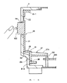
図20及び図21を参照して従来の電子機器の押し釦装置のリンク機構の第2の例を説明する。このリンク機構は複数のL字形のレバー部材190(図20及び図21ではそのうちの1つのみを示す。)を有し、各レバー部材は垂直な押し部材193と水平なアーム194とを有する。垂直な押し部材193の上端にはヒンジ192が設けられ、ヒンジ192の上には取り付け部191が装着されている。この取り付け部191は電子機器のキャビネットに取り付けられている。
【0006】
押し部材193の外面には突起状の釦199が設けられている。アーム194の先端は、プリント配線基板200に設けられた押し釦式スイッチ220上に配置されている。図21に示すように、釦199を指で押すと、L字形のレバー部材190はヒンジ192を通る紙面に垂直な枢動軸線周りに枢動し、レバー部材のアーム194の先端は水平方向に移動する。それによって押し釦式スイッチ220が作動する。
【0007】
【発明が解決しようとする課題】
従来の電子機器の押し釦装置のリンク機構では、設計変更によって押し釦の位置を変えることが困難であった。例えば、押し釦の位置を押し部材183、193上で上下方向に沿って変化させると、力のモーメントの腕の長さが変化し、押し釦式スイッチに作用する力の大きさが変化する。押し釦の位置を水平方向に沿って変化させると、力の作用線とスイッチに加わる力の作用線がずれ、レバー部材が捻れる。従って、押し釦スイッチに加わる力が変化し、操作感が悪くなる。
【0008】
図20及び図21の例では、アーム194の先端は水平方向に移動する。従って、この例では横方向に力を加えることによって操作するように構成された縦型のスイッチを使用する必要がある。縦型のスイッチは、図18及び図19の例のような平面型のスイッチと比較して価格が高いという欠点がある。
【0009】
また、これらの例では、ヒンジによってレバー部材が片持ち支持された構造となっており、モールド成型によってこれを製造するとき、ヒンジの肉薄部にて曲がり易く、不良品が発生する可能性がある。
【0010】
従って、本発明は、押し釦の位置を自由に選択することが比較的容易な電子機器及びそのような押し釦装置のリンク装置を提供することを目的とする。
【0011】
本発明は、押し釦装置の操作性に優れた電子機器を提供することを目的とする。
【0012】
【課題を解決するための手段】
本発明によると、電子機器を操作するための釦が設けられ、該釦に加えられた力によって該電子機器のメインサーキット用のプリント配線基板に配設された電気スイッチを操作するように構成された1つの部材からなる伝達機構を備えた電子機器において、上記伝達機構が、
一端が上記電子機器に第1の弾部を介して折れ曲がり自在に結合され、上記釦に加えられた力によって折れ曲がる第1のレバー部材と、
一端が上記電子機器に第2の弾部を介して折れ曲がり自在に結合される垂直部分と、上記垂直部分から上記垂直部分と直角方向でかつ上記釦と反対の方向に突出し、上記垂直部分と一体に変位することにより先端部が電気スイッチを操作するアームを備えた第2のレバー部材と、
上記第1のレバー部材と上記第2のレバー部材とを連結し、上記第1のレバー部材の折れ曲がりによる移動を上記第2のレバー部材の上記垂直部分を介して上記アームの上記先端部に伝達する第3の弾部と、を有する。
【0013】
本発明によると、電子機器に設けられた釦に加えられた力を、該電子機器の所定の位置に設けられた電気スイッチまで伝達するための伝達機構と、上記電子機器に固定するための取り付け部を備えた枠状部からなり、上記伝達機構及び上記枠状部が1つの部材からなる伝達装置において、上記伝達機構が、
一端が上記電子機器に第1の弾部を介して折れ曲がり自在に結合され、上記釦に加えられた力によって折れ曲がる第1のレバー部材と、
一端が上記電子機器に第2の弾部を介して折れ曲がり自在に結合される垂直部分と、上記垂直部分から上記垂直部分と直角方向でかつ上記釦と反対の方向に突出し、上記垂直部分と一体に変位することにより先端部が電気スイッチを操作するアームを備えた第2のレバー部材と、
上記第1のレバー部材と上記第2のレバー部材とを連結し、上記第1のレバー部材の折れ曲がりによる移動を上記第2のレバー部材の上記垂直部分を介して上記アームの上記先端部に伝達する第3の弾部と、を有する。尚、弾部は折り曲げ部又はヒンジと言い換えてよい。
【0014】
上述のように、リンク機構は両側にて固定され、第1のレバー部材と第2のレバー部材は互いに異なる枢動軸周りに回転するから、上側の下側の押し釦の位置を変更しても良好な操作感が得られる。見方を変えると、2つのレバー部材を1つの連結部材によって連結した構造を有するから、2つのレバー部材の長さを変化させることによって釦を押すための力及び釦の移動のストロークが微妙に変化し、操作感が良好な釦装置を得ることができる。
【0015】
【発明の実施の形態】
図1を参照して、本発明の押し釦装置のリンク機構が装着された電子機器の例として、VTR(ビデオテープレコーダ)を説明する。VTR1は本体2とフロントパネル即ち、操作パネル3を有し、操作パネル3にはテープカセット挿入口4、表示パネル5、押し釦等が装着されている。尚、VTR1の前端の下側には1対の脚部7−1、7−2が装着されている。
【0016】
図2を参照してフロントパネル3に設けられた押し釦を説明する。押し釦は、円形の再生/停止釦100、その両側の早送り/キュー釦102及び巻き戻し/レビュー釦105、その下側の録画釦101及び一時停止釦106等を含む。再生/停止釦100の表面には、上側に三角形、下側に四角形が表示されている。三角形の部分を押すと、再生モードとなり、四角形の部分を押すと停止モードとなる。
【0017】
停止モードの時に、早送り/キュー釦102を押すと、早送りモードとなり、画像を表示することなくテープが早送りされる。再生モードのときに早送り/キュー釦102を押すと、キューモードとなり、画像を表示しながらテープが早送りされる。停止モードの時に、巻き戻し/レビュー釦105を押すと、巻き戻しモードとなり、画像を表示することなくテープが巻き戻される。再生モードのときに巻き戻し/レビュー釦105を押すと、レビューモードとなり、画像を表示しながらテープが巻き戻される。フロントパネル3にはこれ以外の押し釦があるがその説明は省略する。
【0018】
図3、図4及び図5を参照して、本発明による電子機器の押し釦のリンク装置の例を説明する。本例のリンク装置は、略矩形のフレーム8とこのフレームの中に配置された6つのリンク部材10、20、30、40、50、60を含む。第1のリンク部材10は録画釦101に対応して設けられ、第2のリンク部材20は早送り/キュー釦102に対応して設けられ、第3及び第4のリンク部材30、40は再生/停止釦100に対応して設けられ、第5のリンク部材50は巻き戻し/レビュー釦105に対応して設けられ、第6のリンク部材60は一時停止釦106に対応して設けられている。
【0019】
録画釦101、早送り/キュー釦102、巻き戻し/レビュー釦105及び一時停止釦106はそれぞれ、第1、第2、第5及び第6のリンク部材10、20、50、60と一体的に形成されてよい。再生/停止釦100は第3及び第4のリンク部材30、40とは別個の部材として構成されてよい。再生/停止釦100の裏面には2つの突起125、127が設けられ、これらの突起はそれぞれ第3及び第4のリンク部材30、40に当接することができるように構成されている。
【0020】
図4にリンク装置の背面の構造を示す。図示のように第2、第3、第4及び第5のリンク部材20、30、40、50はフレーム8の上枠部材8−1から下枠部材8−2まで延在しているが、第1及び第6のリンク部材10、60は横枠部材8−3、8−4の突起8−3A、8−4Aから下枠部材8−2まで延在している。これらの隣接するリンク部材の間には間隙が形成されている。
【0021】
フレーム8には、このリンク装置を電子部品のキャビネット3に取り付けるための取付部が設けられてよい。本例では、上枠部材8−1の下側に第1の取付部8−11が設けられ、下枠部材8−2の上側にも同様に第2の取付部(図示なし)が設けられている。横枠部材8−2、8−3にはそれぞれ第3の取付部8−31、8−32、8−41、8−42が設けられている。これらの取付部はフレーム8と一体的に形成されてよい。
【0022】
図5に示すように、第1〜第6のリンク部材10、20、30、40、50、60は真っ直ぐではなく湾曲してよく、また途中で幅が変化してよい。フレーム8及びリンク部材10、20、30、40、50、60は、モールド成型によって形成されてよく、好ましくは単一の部材より形成される。こうして、フレーム8及びリンク部材10、20、30、40、50、60を一体成型によって単一の部材より形成する場合、各リンク部材の両端はフレームに接続されている。従って、成型工程にて、リンク部材が薄肉のヒンジを含んでも、変形等によって不良品が発生する可能性が少ない。この場合、フレーム8は図示のように閉じた四角形であってよいが、一辺が欠けた四角形であってもよく、必要に応じて所望の形状が選択される。
【0023】
重要なのは、各リンク部材の両端は、互いに異なる位置にてフレームにそれぞれ接続され、フレームとフレームに接続されたリンク部材は一体的な構造となっている。こうしてフレームにリンク部材の両端が支持されているため、成型工程にて各リンク部材が変形することが防止される。
【0024】
図6〜図11を参照して、各リンク部材の構造を説明する。先ず、図6、図7及び図8を参照して第2のリンク部材20を説明する。第2のリンク部材20は第1のヒンジ22と第1のレバー部材23と第2のヒンジ24と連結部材25と第3のヒンジ26とT字形の第2のレバー部材27と第4のヒンジ28とを有する。第1〜第4のヒンジ22、24、26、28は図示のように、リンク部材20の薄肉部として構成されてよい。
【0025】
第1のレバー部材23は垂直に配置されてよく、その外面には早送り/キュー釦102が装着されている。上述のように、早送り/キュー釦102は第1のレバー部材23と一体的に形成されてよい。早送り/キュー釦102はフロントパネル3の開口部3Aより突出するように設けられている。第1のヒンジ22及び第4のヒンジ28はそれぞれフレームの上枠部材8−1及び下枠部材8−2に装着されている。フレームの上枠部材8−1及び下枠部材8−2はフロントパネル3に装着される。
【0026】
T字形の第2のレバー部材27は垂直部分27Aと水平なアーム27Bとを有し、アーム27Bの先端は、プリント配線基板200に装着されたスイッチ212上に配置されている。
【0027】
図8に示すように、早送り/キュー釦102を押すと、第1のレバー部材23は第1のヒンジ22を通る紙面に垂直な枢動軸線周りに枢動する。それによって第1のレバー部材23の下端は矢印にて示すように水平方向内方に移動する。第1のレバー部材23の下端の移動は、連結部材25を介してT字形の第2のレバー部材27に伝達される。それによって、第2のレバー部材27は第4のヒンジ28を通る紙面に垂直な枢動軸線周りに枢動する。第2のレバー部材27のアーム27Bの先端は下方に移動し、スイッチ212が作動する。
【0028】
第1のレバー部材23は反時計方向に枢動し、第2のレバー部材27は時計方向に枢動する。従って、第1のレバー部材23の下端の運動軌跡と第2のレバー部材27の上端の運動軌跡は同一とはならない。連結部材25の両端には第2及び第3のヒンジ24、26が設けられ、この2つのヒンジ24、26の変形によって、連結部材25は自由に移動することができる。連結部材25の移動によって2つの運動軌跡のずれが吸収される。
【0029】
図9及び図10を参照して第3及び第4のリンク部材30、40を説明する。第3及び第4のリンク部材30、40は第1のヒンジ32、42と第1のレバー部材33、43と第2のヒンジ34、44と連結部材35、45と第3のヒンジ36、46とT字形の第2のレバー部材37、47と第4のヒンジ38、48とを有する。第1〜第4のヒンジ32、42、34、44、36、46、38、48は図示のように、リンク部材30、40の薄肉部として構成されてよい。
【0030】
第1のレバー部材33、43は垂直に配置されてよく、その前側には再生/停止釦100が配置されている。再生/停止釦100、フロントパネル3の開口部3B内に配置されている。第1のヒンジ32、42及び第4のヒンジ38、48はそれぞれフレームの上枠部材8−1及び下枠部材8−2に装着されている。フレームに設けられた取付部8−21は図示のようにフロントパネル3に装着される。
【0031】
T字形の第2のレバー部材37、47は垂直部分37A、47Aと水平なアーム37B、47Bとを有し、アーム37B、47Bの先端は、プリント配線基板200に装着されたスイッチ213、214上に配置されている。
【0032】
図2に示したように、再生/停止釦100の表面の上側には、再生を意味する三角形が付され、下側には停止を意味する四角形が付されている。一方、再生/停止釦100の裏面には、それに対応した突起125(図9、図3)、127(図10、図3)が設けられている。図5のX印は、突起125、127の位置を示す。図示のように、再生の表示(三角形)に対応して設けられた上側の突起125は、第3のリンク部材30の第1のレバー部材33の上に配置され、停止の表示(四角形)に対応して設けられた下側の突起127は、第4のリンク部材40の第1のレバー部材43の上に配置されている。
【0033】
再生/停止釦100は、図9及び図10に示すように、枢動軸121周りに枢動可能に装着されている。この枢動軸121は、再生/停止釦100の背後にて再生/停止釦100の中央を横断し、水平に即ち、紙面に垂直に配置されている。尚、枢動軸121に隣接してばね129が装着され、このばね129によって再生/停止釦100は元の位置に復元するように付勢されている。
【0034】
図9を参照する。再生/停止釦100の上側の再生の表示(三角形)を押すと、再生/停止釦100は枢動軸121周りに時計方向に回転し、上側の突起125が内方に移動する。それによって第3のリンク部材30の第1のレバー部材33は第1のヒンジ32周りに枢動する。第1のレバー部材33の下端は矢印にて示すように水平方向内方に移動する。第1のレバー部材33の下端の移動は、連結部材35を介してT字形の第2のレバー部材37に伝達される。それによって、第2のレバー部材37は第4のヒンジ38を通る紙面に垂直な枢動軸線周りに枢動する。第2のレバー部材37のアーム37Bの先端は下方に移動し、スイッチ213が作動する。
【0035】
図10を参照する。再生/停止釦100の下側の停止の表示(四角形)を押すと、再生/停止釦100は枢動軸121周りに反時計方向に回転し、下側の突起127が内方に移動する。それによって第4のリンク部材40の第1のレバー部材43は第1のヒンジ42周りに枢動する。第1のレバー部材43の下端は矢印にて示すように水平方向内方に移動する。第1のレバー部材43の下端の移動は、連結部材45を介してT字形の第2のレバー部材47に伝達される。それによって、第2のレバー部材47は第4のヒンジ48を通る紙面に垂直な枢動軸線周りに枢動する。第2のレバー部材47のアーム47Bの先端は下方に移動し、スイッチ214が作動する。
【0036】
図11を参照して第1のリンク部材10を説明する。第1のリンク部材10は第1のヒンジ12と第1のレバー部材13と第2のヒンジ14と連結部材15と第3のヒンジ16とT字形の第2のレバー部材17と第4のヒンジ18とを有する。第1〜第4のヒンジ12、14、16、18は図示のように、リンク部材10の薄肉部として構成されてよい。
【0037】
第1のレバー部材13は垂直に配置されてよく、その外面には録画釦101が装着されている。上述のように、録画釦101は第1のレバー部材13と一体的に形成されてよい。録画釦101はフロントパネル3の開口部3Cより突出するように設けられている。図4を参照して説明したように、第1のヒンジ12はフレームの横枠部材8−3の突起8−3Aに装着されている。第4のヒンジ18はそれぞれフレームの下枠部材8−2に装着されている。
【0038】
第1のリンク部材10の構造は、図6、図7及び図8を参照して説明した第2のリンク部材20と比較して、縦の長さが短く、第1のヒンジ12がフレームの上枠部材8−1の代わりに横枠部材8−3の突起8−3Aに装着されている点が異なる。また、第1のレバー部材13には、早送り/キュー釦102の代わりに録画釦101が装着されている点が異なる。しかしながら、その動作は基本的には第2のリンク部材20と同様である。
【0039】
即ち、録画釦101を押すと、第1のレバー部材13は第1のヒンジ12を通る紙面に垂直な枢動軸線周りに枢動する。それによって第1のレバー部材13の下端は矢印にて示すように水平方向内方に移動する。第1のレバー部材13の下端の移動は、連結部材15を介してT字形の第2のレバー部材17に伝達される。それによって、第2のレバー部材17は第4のヒンジ18を通る紙面に垂直な枢動軸線周りに枢動する。第2のレバー部材17のアーム17Bの先端は下方に移動し、スイッチ211が作動する。
【0040】
尚、巻き戻し/レビュー釦105に対応して設けられた第5のリンク部材50は、第2のリンク部材20と同様な構造及び機能を有してよい。又、一時停止釦106に対応して設けられた第6のリンク部材60は、第1のリンク部材10と同様な構造及び機能を有してよい。従って、第5のリンク部材50及び第6のリンク部材60の構造及び機能の説明は省略する。
【0041】
上述の本発明のリンク装置の第1の例では、リンク部材10、20、30、40、50、60は互いに異なる第1及び第4のヒンジを通る枢動軸周りに回転し、第1及び第4のヒンジはそれぞれ固定されている。従って、リンク部材の第1のレバー部材に装着された押し釦の操作感が良好となる特徴を有する。
【0042】
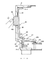
図12及び図13を参照して本発明の第2の例を説明する。図12には、本例のリンク機構に含まれる1つのリンク部材70のみを示す。このリンク部材70は第1のヒンジ72と第1のレバー部材73と第2のヒンジ74と連結部材75と第3のヒンジ76とT字形の第2のレバー部材77と第4のヒンジ78とを有する。第2のレバー部材77のアーム77Bの下側にはプリント配線基板200に装着されたスイッチ217が配置されている。
【0043】
本例のリンク部材70を上述のリンク部材10、20、30、40、50、60と比較すると、ヒンジの構造及び第1のレバー部材73の構造が異なる。本例の第1〜第4のヒンジ72、74、76、78は図示のように、軸72A、74A、76A、78Aを含む蝶番によって構成されている。第1のヒンジ72及び第4のヒンジ78の軸72A、78Aは、フレーム8−1、8−2に装着されてよいが、キャビネット3に直接装着されてよい。ヒンジとして薄肉部を使用する代わりに蝶番を使用することによって、ヒンジの剛性が高くなる利点がある。特に、ヒンジの捻れに対する剛性が高くなる。
【0044】
第1のレバー部材73は、垂直部分73−1と水平部分73−2からなるL字形に形成されてよい。その外面には適当な押し釦107が装着されている。この例では、押し釦107はキャビネット3の前面の凹部に配置されたばね108によって復元力を付与されている。
【0045】
押し釦107は第1のレバー部材73の垂直部分73−1に装着されている。従って、力の作用線とスイッチ217に加わる力の作用線はずれる。即ち、2つの力の作用線は同一平面上にない。押し釦107に加えられる力によって、第2のレバー部材77には捻り力が作用する。しかしながら、ヒンジは蝶番によって構成されているため、十分が剛性があり、第2のレバー部材77に捻り力が加えられてもヒンジが変形することはない。第1のレバー部材73の水平部分73−2の長さを変化させることによって押し釦107の水平方向の位置を変化さえることができる。
【0046】
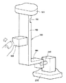
図14及び図15を参照して本発明の第3の例を説明する。図14及び図15には、本例のリンク機構に含まれる1つのリンク部材80のみを示す。このリンク部材80は第1のヒンジ82と第1のレバー部材83と弾性部材85とL字形の第2のレバー部材87と第2のヒンジ88とを有する。
【0047】
本例のリンク部材80を上述のリンク部材10、20、30、40、50、60と比較すると、ヒンジ82、88の構造が異なり、また、連結部材及びその両側のヒンジの代わりに弾性部材85を使用する点が異なる。本例の第1及び第2のヒンジ82、88は薄い板ばね82A、88Aとそれを保持する溝82B、88Bからなる。第1及び第2のヒンジの板ばね82A、88A、第1及び第2のレバー部材83、87及び弾性部材85は一体的に構成されてよい。第1及び第2のヒンジ82、88の溝82B、88Bはフレーム8−1、8−2に設けられてよく、又はキャビネット3に直接設けられてよい。尚、この図では、連結部材全体が弾性部材85となっているが、連結部材の一部、例えば、中央部分のみを弾性部材となるように構成してよい。
【0048】
図15に示すように、第1のレバー部材83に設けられた押し釦109を押すと、第1のレバー部材83は第1のヒンジ82を通る枢動軸線周りに枢動し、その変位は弾性部材85を経由して第2のレバー部材87に伝達される。第2のレバー部材87は第2のヒンジ88を通る枢動軸線周りに枢動し、アーム87Bの先端は下方に移動する。それによって、アーム87Bの先端の下側に配置されたスイッチ218が作動する。
【0049】
第1のレバー部材83は反時計方向に枢動し、第2のレバー部材87は時計方向に枢動する。従って、第1のレバー部材83の下端の運動軌跡と第2のレバー部材87の上端の運動軌跡は同一とはならない。本例では、弾性部材85の変形によって、2つの運動軌跡の間のずれが吸収される。
【0050】
図12〜図15に示した第2及び第3の例において、リンク部材70、80は、早送り/キュー釦102又は巻き戻し/レビュー釦105を操作するためのものであってよく、又は録画釦101又は一時停止釦106を操作するためものであってよい。勿論、再生/停止釦100を操作するためのものであってよい。
【0051】
図16及び図17を参照して、再生/停止釦100の第2の例を説明する。本例の再生/停止釦100は図16A及び図16Bに示すように略円盤状のカバー部材150と図16C及び図16Dに示すように枠部材160とを有する。カバー部材150の表面には、再生を意味する上側の三角形と停止を意味する下側の四角形が表示されている。また、三角形の上側には、触覚にて再生/停止釦100を検知することができるように小さな突起150Aが設けられている。カバー部材150の裏面には互いに直交する直径に沿って配置された2対の突起が形成されている。
【0052】
水平な直径に沿って配置された第1の対の突起151、153は、それぞれ、枢動軸151A、153A及びそれを支持する支持部材151B、153Bを含む。垂直な直径に沿って配置された第2の対の突起155、157は、それぞれ、当接部155A、157A及びその横の肩部155B、157Bを含む。カバー部材150の裏面には更に水平な直径に沿って第3の対の突起159A、159Bが設けられている。
【0053】
枠部材160はカバー部材150を受け入れるための凹部160Aを有し、この凹部の底面には、カバー部材150の第1及び第2の対の突起151、153、155、157に対応して且つそれを受け入れるための2対の開口161、163、165、167が設けられている。第1の対の開口161、163の縁には、枢動軸151A、153Aを受け入れるための軸受け部162、164が設けられている。第2の対の開口165、167には、開口を横断する方向に延在するばね部材166、168が設けられている。ばね部材166、168は図示のように枠部材160の一部の薄肉部として枠部材160と一体構造に形成されてよい。
【0054】
枠部材160の凹部160Aの底面には更に、第1の対の開口161、163の間に突起169が設けられている。この突起はカバー部材150の第3の対の突起159A、159Bに対応して設けられ、組立工程にて、カバー部材150が枠部材160に対して誤った方向に装着されることを防止するために設けられている。
【0055】
枠部材160の周囲には4本の爪171、172、173、174が設けられ、この爪の先端には突起が設けられている。この4本の爪はキャビネットの対応する開口部に挿入されるように構成されている。図示のように、4本の爪のうち上側の2本は比較的長く、下側の2本は比較的短くてよい。カバー部材及び枠部材はそれぞれ、モールド成型法によって一体的に形成されてよい。
【0056】
本例の再生/停止釦100は、カバー部材150を枠部材160の凹部160Aに挿入することによって組み立てられる。カバー部材150の第1及び第2の対の突起151、153、155、157はそれぞれ対応する枠部材160の第1及び第2の対の開口161、163、165、167に挿入される。カバー部材150の枢動軸151A、153Aはそれぞれ対応する枠部材160の軸受け部162、164に係合する。カバー部材150の肩部155B、157Bは枠部材160のばね部材166、168の当接する。
【0057】
枠部材160の突起169は、カバー部材150の第3の対の突起159A、159Bの間に配置される。枠部材160の突起169は、カバー部材150と枠部材160の間の水平方向の相対的なずれを阻止するためのストッパとして機能させてもよい。カバー部材150の第3の対の突起159A、159Bは枠部材160の凹部160Aの底面に当接する。カバー部材150の第3の対の突起159A、159Bは、カバー部材150と枠部材160が互いに近づくのを阻止するためのストッパとして機能する。枢動軸151A、153Aと軸受け部162、164の係合によって、カバー部材150と枠部材160は互いに離れる方向に移動することが阻止される。
【0058】
図17に示すように、組み立てられた本例の再生/停止釦100はキャビネット3の開口3Bに挿入される。図示のように、カバー部材150の第2の対の突起155、157の当接部155A、157Aはそれぞれ第3及び第4のリンク部材30、40に当接している。
【0059】
カバー部材150の表面の再生を意味する三角形の部分を押すと、カバー部材150は枢動軸151A、153A周りに時計方向に枢動し、カバー部材150の第2の対の突起の上側の突起155の当接部155A及び肩部155Bが内方に移動する。当接部155Aの移動によって第3のリンク部材30が移動する。肩部155Bの移動によってばね部材166は変形し、カバー部材150はばね部材166より復元力、即ち、反時計方向の枢動力を受ける。
【0060】
カバー部材150の表面の停止を意味する四角形の部分を押すと、カバー部材150は枢動軸151A、153A周りに反時計方向に枢動し、カバー部材150の第2の対の突起の下側の突起157の当接部157A及び肩部157Bが内方に移動する。当接部157Aの移動によって第4のリンク部材40が移動する。肩部157Bの移動によってばね部材168は変形し、カバー部材150はばね部材168より復元力、即ち、時計方向の枢動力を受ける。
【0061】
以上本発明の実施例について詳細に説明してきたが、本発明は上述の実施例に限ることなく本発明の要旨を逸脱することなく他の種々の構成が採り得ることは当業者にとって容易に理解されよう。
【0062】
【発明の効果】
本発明によると、押し釦の位置を自由に選択することが比較的容易な且つ押し釦装置の操作性が良好な電子機器及びそのような押し釦装置のリンク装置を提供することができる利点を有する。
【0063】
本発明によると、比較的高価な縦型のスイッチを使用すること無く、比較的安価な平面型のスイッチを使用することができる利点を有する。
【0064】
本発明によると、レバー部材がヒンジによって片持ち支持された構造を含まないため、モールド成型によってこれを製造するとき、ヒンジの肉薄部にて湾曲して不良品が発生するということが回避される利点を有する。
【図面の簡単な説明】
【図1】本発明の電子機器の外観を示す図である。
【図2】図1の電子機器のフロントパネルの押し釦を示す図である。
【図3】本発明のリンク装置の正面の構造を示す斜視図である。
【図4】本発明のリンク装置の背面の構造を示す斜視図である。
【図5】本発明のリンク装置と押し釦の関係を示す正面図である。
【図6】本発明のリンク装置のリンク部材の斜視図である。
【図7】図3及び図5の線A−Aに沿った本発明のリンク装置の断面図である。
【図8】押し釦を押した状態を示す図3及び図5の線A−Aに沿った本発明のリンク装置の断面図である。
【図9】図3及び図5の線B−Bに沿った本発明のリンク装置の断面図である。
【図10】図3及び図5の線C−Cに沿った本発明のリンク装置の断面図である。
【図11】図3及び図5の線D−Dに沿った本発明のリンク装置の断面図である。
【図12】本発明のリンク装置の第2の例の一部を示す斜視図である。
【図13】図12の第2の例の断面図である。
【図14】本発明のリンク装置の第3の例の一部を示す斜視図である。
【図15】押し釦を押した状態を示す図14の第3の例の斜視図である。
【図16】本発明のリンク装置の釦の構造を示す図である。
【図17】図16の釦の構造を示す断面図である。
【図18】従来のリンク装置の第1の例の一部を示す斜視図である。
【図19】図18の第1の例の断面図である。
【図20】従来のリンク装置の第2の例の一部を示す斜視図である。
【図21】図20の第2の例の断面図である。
【符号の説明】
1…電子機器(VTR)、 2…本体、 3…フロントパネル、 4…カセット挿入口、 5…表示パネル、 7−1,7−1…脚部、 8…フレーム、 10,20,30,40,50,60,70…リンク部材、 100,101,102,105,106…釦、 200…プリント配線基板、 210,211,212,213,214,217,218,220…スイッチ[0001]
BACKGROUND OF THE INVENTION
The present invention relates to an electronic device such as a VTR (video tape recorder), and more particularly to a link mechanism of a push button device mounted on a front operation panel.
[0002]
[Prior art]
An operation push button is disposed on the front panel of the electronic device, and a link mechanism is provided to connect the push button and a switch disposed on the printed wiring board. Conventionally, various types and structures of link mechanisms have been developed and used.
[0003]
A first example of a link mechanism of a push button device of a conventional electronic device will be described with reference to FIGS. This link mechanism has a plurality of L-
[0004]
A
[0005]
A second example of a link mechanism of a push button device of a conventional electronic device will be described with reference to FIGS. This link mechanism has a plurality of L-shaped lever members 190 (only one of which is shown in FIGS. 20 and 21), and each lever member has a vertical pushing
[0006]
A
[0007]
[Problems to be solved by the invention]
In a conventional link mechanism of a push button device of an electronic device, it is difficult to change the position of the push button by a design change. For example, when the position of the push button is changed along the vertical direction on the
[0008]
20 and 21, the tip of the
[0009]
Moreover, in these examples, the lever member is cantilevered by the hinge, and when it is manufactured by molding, it is easy to bend at the thin portion of the hinge, which may cause defective products. .
[0010]
Accordingly, an object of the present invention is to provide an electronic device in which the position of the push button can be freely selected and a link device for such a push button device.
[0011]
An object of this invention is to provide the electronic device excellent in the operativity of a pushbutton apparatus.
[0012]
[Means for Solving the Problems]
According to the present invention, a button for operating an electronic device is provided, and an electric switch disposed on a printed circuit board for a main circuit of the electronic device is operated by a force applied to the button. In an electronic device equipped with a transmission mechanism consisting of a single member,The transmission mechanism is
A first lever member, one end of which is foldably coupled to the electronic device via a first bullet, and is bent by a force applied to the button;
One end is connected to the electronic device via a second bullet so that it can be bent freely.A vertical portion that is perpendicular to the vertical portion from the vertical portion andProjecting in the opposite direction of the buttonThe tip part is displaced by being displaced integrally with the vertical part.A second lever member having an arm for operating the electric switch;
The first lever member and the second lever member are connected, and the movement of the first lever member by bending is the second lever member.The tip of the arm through the vertical portion of theAnd a third bullet portion to be transmitted to.
[0013]
According to the present invention, a transmission mechanism for transmitting a force applied to a button provided on an electronic device to an electric switch provided at a predetermined position of the electronic device, and an attachment for fixing to the electronic device. A transmission device comprising a frame-shaped portion provided with a portion, wherein the transmission mechanism and the frame-shaped portion are formed of one member;The transmission mechanism is
A first lever member, one end of which is foldably coupled to the electronic device via a first bullet, and is bent by a force applied to the button;
One end is connected to the electronic device via a second bullet so that it can be bent freely.A vertical portion that is perpendicular to the vertical portion from the vertical portion andProjecting in the opposite direction of the buttonThe tip part is displaced by being displaced integrally with the vertical part.A second lever member having an arm for operating the electric switch;
The first lever member and the second lever member are connected, and the movement of the first lever member by bending is the second lever member.The tip of the arm through the vertical portion of theAnd a third bullet portion to be transmitted to. In addition, you may paraphrase a bullet part as a bending part or a hinge.
[0014]
As described above, the link mechanism is fixed on both sides, and the first lever member and the second lever member rotate around different pivot axes, so the position of the upper lower push button is changed. A good operational feeling can be obtained. From a different perspective, it has a structure in which two lever members are connected by one connecting member, so that the force to push the button and the stroke of the button move slightly by changing the length of the two lever members. In addition, it is possible to obtain a button device having a good operation feeling.
[0015]
DETAILED DESCRIPTION OF THE INVENTION
With reference to FIG. 1, a VTR (video tape recorder) will be described as an example of an electronic device to which the link mechanism of the push button device of the present invention is attached. The VTR 1 has a
[0016]
The push buttons provided on the
[0017]
When the fast forward /
[0018]
With reference to FIGS. 3, 4 and 5, an example of a link device for a push button of an electronic device according to the present invention will be described. The link device of this example includes a substantially
[0019]
The
[0020]
FIG. 4 shows the structure of the back side of the link device. As shown, the second, third, fourth and
[0021]
The
[0022]
As shown in FIG. 5, the first to
[0023]
Importantly, both ends of each link member are connected to the frame at different positions, and the frame and the link member connected to the frame have an integral structure. Since both ends of the link member are supported by the frame in this way, each link member is prevented from being deformed in the molding process.
[0024]
The structure of each link member will be described with reference to FIGS. First, the
[0025]
The
[0026]
The T-shaped
[0027]
As shown in FIG. 8, when the fast forward /
[0028]
The
[0029]
The 3rd and
[0030]
The
[0031]
The T-shaped
[0032]
As shown in FIG. 2, a triangle indicating playback is attached to the upper side of the surface of the playback /
[0033]
As shown in FIGS. 9 and 10, the play /
[0034]
Please refer to FIG. When the playback display (triangle) on the upper side of the playback /
[0035]
Please refer to FIG. When the lower stop indication (square) on the play /
[0036]
The
[0037]
The
[0038]
The structure of the
[0039]
That is, when the
[0040]
The
[0041]
In the first example of the link device of the present invention described above, the
[0042]
A second example of the present invention will be described with reference to FIGS. FIG. 12 shows only one
[0043]
When the
[0044]
The
[0045]
The
[0046]
A third example of the present invention will be described with reference to FIGS. 14 and 15 show only one
[0047]
When the
[0048]
As shown in FIG. 15, when the
[0049]
The
[0050]
In the second and third examples shown in FIGS. 12 to 15, the
[0051]
A second example of the play /
[0052]
The first pair of
[0053]
The
[0054]
A
[0055]
Four
[0056]
The play /
[0057]
The
[0058]
As shown in FIG. 17, the assembled play /
[0059]
When a triangular portion representing the regeneration of the surface of the
[0060]
When a square portion, which means the stop of the surface of the
[0061]
Although the embodiments of the present invention have been described in detail above, the present invention is not limited to the above-described embodiments, and those skilled in the art can easily understand that various other configurations can be adopted without departing from the gist of the present invention. It will be done.
[0062]
【The invention's effect】
According to the present invention, there is an advantage that it is possible to provide an electronic device in which the position of the push button can be freely selected and the operability of the push button device is good, and a link device of such a push button device. Have.
[0063]
According to the present invention, there is an advantage that a relatively inexpensive planar switch can be used without using a relatively expensive vertical switch.
[0064]
According to the present invention, since the lever member does not include a structure in which the lever member is cantilevered by the hinge, it is avoided that a defective product is generated due to bending at the thin portion of the hinge when it is manufactured by molding. Have advantages.
[Brief description of the drawings]
FIG. 1 is a diagram illustrating an external appearance of an electronic apparatus according to the invention.
FIG. 2 is a diagram showing push buttons on the front panel of the electronic device of FIG. 1;
FIG. 3 is a perspective view showing a front structure of the link device of the present invention.
FIG. 4 is a perspective view showing the structure of the back surface of the link device of the present invention.
FIG. 5 is a front view showing the relationship between the link device of the present invention and a push button.
FIG. 6 is a perspective view of a link member of the link device of the present invention.
7 is a cross-sectional view of the link device of the present invention taken along line AA in FIGS. 3 and 5. FIG.
8 is a cross-sectional view of the link device of the present invention taken along line AA in FIGS. 3 and 5 showing a state in which the push button is pushed. FIG.
9 is a cross-sectional view of the link device of the present invention along the line BB of FIGS. 3 and 5. FIG.
10 is a cross-sectional view of the link device of the present invention along line CC in FIGS. 3 and 5. FIG.
11 is a cross-sectional view of the link device of the present invention along the line DD in FIGS. 3 and 5. FIG.
FIG. 12 is a perspective view showing a part of a second example of the link device of the present invention.
13 is a cross-sectional view of the second example of FIG.
FIG. 14 is a perspective view showing a part of a third example of the link device of the present invention.
15 is a perspective view of the third example of FIG. 14 showing a state where a push button is pressed.
FIG. 16 is a diagram showing a button structure of the link device of the present invention.
17 is a cross-sectional view showing the structure of the button of FIG.
FIG. 18 is a perspective view showing a part of a first example of a conventional link device.
19 is a cross-sectional view of the first example of FIG.
FIG. 20 is a perspective view showing a part of a second example of a conventional link device.
FIG. 21 is a sectional view of the second example of FIG. 20;
[Explanation of symbols]
DESCRIPTION OF SYMBOLS 1 ... Electronic device (VTR), 2 ... Main body, 3 ... Front panel, 4 ... Cassette insertion slot, 5 ... Display panel, 7-1, 7-1 ... Leg part, 8 ... Frame, 10, 20, 30, 40 , 50, 60, 70 ... link member, 100, 101, 102, 105, 106 ... button, 200 ... printed wiring board, 210, 211, 212, 213, 214, 217, 218, 220 ... switch
Claims (9)
上記伝達機構が、
一端が上記電子機器に第1の弾部を介して折れ曲がり自在に結合され、上記釦に加えられた力によって折れ曲がる第1のレバー部材と、
一端が上記電子機器に第2の弾部を介して折れ曲がり自在に結合される垂直部分と、上記垂直部分から上記垂直部分と直角方向でかつ上記釦と反対の方向に突出し、上記垂直部分と一体に変位することにより先端部が電気スイッチを操作するアームを備えた第2のレバー部材と、
上記第1のレバー部材と上記第2のレバー部材とを連結し、上記第1のレバー部材の折れ曲がりによる移動を上記第2のレバー部材の上記垂直部分を介して上記アームの上記先端部に伝達する第3の弾部と、
を有することを特徴とする電子機器。A button for operating the electronic device is provided, and a single member configured to operate an electric switch disposed on the printed circuit board for the main circuit of the electronic device by a force applied to the button. In an electronic device equipped with a transmission mechanism
The transmission mechanism is
A first lever member, one end of which is foldably coupled to the electronic device via a first bullet, and is bent by a force applied to the button;
One end protrudes in a direction opposite to the second vertical portion bullet portion Ru coupled freely bent through, the vertical portion of the vertical portion perpendicular to the direction a and the button on the electronic device, the vertical part integral A second lever member having an arm whose tip portion operates an electric switch by being displaced to
The first lever member and the second lever member are connected, and the movement of the first lever member due to bending is transmitted to the tip end portion of the arm via the vertical portion of the second lever member. A third bullet to
An electronic device comprising:
上記伝達機構が、
一端が上記電子機器に第1の弾部を介して折れ曲がり自在に結合され、上記釦に加えられた力によって折れ曲がる第1のレバー部材と、
一端が上記電子機器に第2の弾部を介して折れ曲がり自在に結合される垂直部分と、上記垂直部分から上記垂直部分と直角方向でかつ上記釦と反対の方向に突出し、上記垂直部分と一体に変位することにより先端部が電気スイッチを操作するアームを備えた第2のレバー部材と、
上記第1のレバー部材と上記第2のレバー部材とを連結し、上記第1のレバー部材の折れ曲がりによる移動を上記第2のレバー部材の上記垂直部分を介して上記アームの上記先端部に伝達する第3の弾部と、
を有することを特徴とする伝達装置。A frame having a transmission mechanism for transmitting a force applied to a button provided on the electronic device to an electrical switch provided at a predetermined position of the electronic device, and a mounting portion for fixing the electronic device to the electronic device In the transmission device, the transmission mechanism and the frame-shaped portion are formed of one member.
The transmission mechanism is
A first lever member, one end of which is foldably coupled to the electronic device via a first bullet, and is bent by a force applied to the button;
One end protrudes in a direction opposite to the second vertical portion bullet portion Ru coupled freely bent through, the vertical portion of the vertical portion perpendicular to the direction a and the button on the electronic device, the vertical part integral A second lever member having an arm whose tip portion operates an electric switch by being displaced to
The first lever member and the second lever member are connected, and the movement of the first lever member due to bending is transmitted to the tip end portion of the arm via the vertical portion of the second lever member. A third bullet to
A transmission device comprising:
Applications Claiming Priority (2)
| Application Number | Priority Date | Filing Date | Title |
|---|---|---|---|
| MYPI99005345A MY122430A (en) | 1999-12-08 | 1999-12-08 | Electronic equipment and transmission device of button device used therein |
| MY9905345 | 1999-12-08 |
Publications (2)
| Publication Number | Publication Date |
|---|---|
| JP2001176350A JP2001176350A (en) | 2001-06-29 |
| JP4401552B2 true JP4401552B2 (en) | 2010-01-20 |
Family
ID=19749845
Family Applications (1)
| Application Number | Title | Priority Date | Filing Date |
|---|---|---|---|
| JP2000309373A Expired - Fee Related JP4401552B2 (en) | 1999-12-08 | 2000-10-10 | Electronic device and button device transmission device used therefor |
Country Status (5)
| Country | Link |
|---|---|
| US (1) | US6570111B2 (en) |
| JP (1) | JP4401552B2 (en) |
| KR (1) | KR100721693B1 (en) |
| CN (1) | CN1216390C (en) |
| MY (1) | MY122430A (en) |
Families Citing this family (45)
| Publication number | Priority date | Publication date | Assignee | Title |
|---|---|---|---|---|
| DE10142503A1 (en) * | 2001-08-30 | 2003-03-20 | Bsh Bosch Siemens Hausgeraete | Electric kitchen appliance |
| JP3090037U (en) * | 2002-05-16 | 2002-11-22 | 船井電機株式会社 | Operation buttons integrated front panel |
| JP3838170B2 (en) * | 2002-07-08 | 2006-10-25 | 株式会社デンソー | Switch structure |
| JP2004103490A (en) * | 2002-09-12 | 2004-04-02 | Orion Denki Kk | Mounting structure for operating button of electric equipment |
| JP2004259537A (en) * | 2003-02-25 | 2004-09-16 | Toshiba Corp | Electronic equipment and push button unit |
| FI115330B (en) * | 2003-06-13 | 2005-04-15 | Nokia Corp | Keypad and method of manufacturing the same |
| US7247807B2 (en) * | 2003-07-07 | 2007-07-24 | Hewlett-Packard Development Company, L.P. | Button having stiffer vertical motion and reduced lateral motion |
| US6867384B1 (en) * | 2003-09-19 | 2005-03-15 | Matsushita Electric Industrial Co., Ltd. | Switching apparatus |
| JP3871136B2 (en) * | 2003-10-03 | 2007-01-24 | 船井電機株式会社 | Switch device |
| DE202004007733U1 (en) * | 2004-05-11 | 2005-09-22 | Schwarzbich, Jörg | control panel |
| JP4218605B2 (en) * | 2004-07-21 | 2009-02-04 | ブラザー工業株式会社 | Switch device and image forming apparatus |
| KR100605257B1 (en) * | 2004-07-22 | 2006-07-28 | 삼성전자주식회사 | Operation button support device of electronic device and electronic device |
| US6984793B1 (en) * | 2004-07-27 | 2006-01-10 | Hewlett-Packard Development Company, L.P. | Multidirectional switch actuator and a personal digital assistant using the same |
| DE102004049435B4 (en) * | 2004-10-08 | 2006-11-16 | Zf Friedrichshafen Ag | Button with cable |
| JP2006210191A (en) * | 2005-01-28 | 2006-08-10 | Orion Denki Kk | Electronic equipment having operation button |
| JP2006221845A (en) * | 2005-02-08 | 2006-08-24 | Funai Electric Co Ltd | Face push button and electronic equipment |
| JP2006278248A (en) * | 2005-03-30 | 2006-10-12 | Orion Denki Kk | Electronic equipment with operation button |
| EP1729314A3 (en) * | 2005-05-31 | 2008-03-05 | Siemens Aktiengesellschaft | Push button switch |
| CN2886781Y (en) * | 2006-02-10 | 2007-04-04 | 鸿富锦精密工业(深圳)有限公司 | Power supply key module structure |
| CN2909350Y (en) * | 2006-04-05 | 2007-06-06 | 鸿富锦精密工业(深圳)有限公司 | panel combination |
| JP4695036B2 (en) * | 2006-07-26 | 2011-06-08 | セイコーインスツル株式会社 | Switch structure and electronic equipment |
| US7256363B1 (en) * | 2006-09-18 | 2007-08-14 | Lear Corporation | Intermediate switch actuator array |
| US7381919B1 (en) * | 2007-02-22 | 2008-06-03 | Inventec Corporation | Lever button of electronic product |
| CN101312099B (en) * | 2007-05-25 | 2011-05-25 | Tcl新技术(惠州)有限公司 | Press key device integrating with machine box plastic rubber panel |
| JP2009043100A (en) * | 2007-08-09 | 2009-02-26 | Fujitsu Ltd | Medium drive unit and electronic device |
| EP2225766A1 (en) * | 2007-12-14 | 2010-09-08 | 3be Berliner Beratungs- Und Beteiligungs-Gmbh | Switch |
| CN201156481Y (en) * | 2007-12-27 | 2008-11-26 | 鸿富锦精密工业(深圳)有限公司 | button device |
| CN101527214B (en) * | 2008-03-07 | 2011-02-16 | 旭丽电子(广州)有限公司 | Key structure and electronic device equipped therewith |
| CN101651053A (en) * | 2008-08-15 | 2010-02-17 | 深圳富泰宏精密工业有限公司 | Side key component and portable electronic device applying same |
| CN101668396B (en) * | 2008-09-02 | 2011-08-24 | 鸿富锦精密工业(深圳)有限公司 | Electronic devices and their key combinations |
| KR100928944B1 (en) * | 2009-08-28 | 2009-11-30 | 주식회사 아이레보 | Security device for pushbutton of electronic door lock and electronic door lock with same |
| JP2011086536A (en) * | 2009-10-16 | 2011-04-28 | Mitsubishi Electric Corp | Push button assembly structure |
| DE102010027799A1 (en) * | 2010-04-15 | 2011-10-20 | BSH Bosch und Siemens Hausgeräte GmbH | Operating device for a domestic appliance and domestic appliance with an operating device |
| WO2011161732A1 (en) * | 2010-06-25 | 2011-12-29 | 三菱電機株式会社 | Push button structure |
| US8417303B2 (en) | 2010-07-09 | 2013-04-09 | Research In Motion Limited | Mobile device case |
| CN102683069B (en) * | 2011-03-08 | 2015-03-18 | 宏达国际电子股份有限公司 | Electronic device |
| CN102110536B (en) * | 2011-03-10 | 2014-01-15 | 鸿富锦精密工业(深圳)有限公司 | Tactile switch key and electronic device with the same |
| DE102014214982A1 (en) | 2014-07-30 | 2016-02-04 | Robert Bosch Gmbh | Power tool |
| CN205542535U (en) * | 2016-02-29 | 2016-08-31 | 欧姆龙株式会社 | Button structure of electronic products and electronic products |
| KR102509067B1 (en) * | 2016-04-08 | 2023-03-13 | 삼성디스플레이 주식회사 | User identifying device, input sensing module of the same and method for user identifying |
| CN109599285B (en) * | 2017-09-30 | 2024-12-03 | 北京小米移动软件有限公司 | Key structure and electronic equipment |
| CN108281307B (en) * | 2018-03-14 | 2025-02-07 | 沈春根 | A switch mechanism |
| CN108597935B (en) * | 2018-07-11 | 2024-04-05 | 中山市狮盾电气有限公司 | Slim type panel switch structure |
| CN111564332B (en) * | 2019-10-08 | 2023-02-24 | 光宝电子(广州)有限公司 | Composite key structure and wireless electronic device using same |
| CN112273892B (en) * | 2020-10-26 | 2022-01-14 | 盐城工业职业技术学院 | Honeycomb type medicine management device |
Family Cites Families (6)
| Publication number | Priority date | Publication date | Assignee | Title |
|---|---|---|---|---|
| US3582584A (en) * | 1968-08-19 | 1971-06-01 | Nibot Corp | Electrical switch having integral plastic parts |
| US3582594A (en) * | 1968-11-15 | 1971-06-01 | Mechanical Enterprises Inc | Actuator useable for electric switches and the like |
| US4877925A (en) * | 1987-10-23 | 1989-10-31 | Clarion Co., Ltd. | Multi-stage push button switch device |
| KR100207699B1 (en) * | 1996-10-30 | 1999-07-15 | 윤종용 | Eject device of portable audio logic deck |
| US6002093A (en) * | 1998-08-21 | 1999-12-14 | Dell Usa, L.P. | Button with flexible cantilever |
| US6215081B1 (en) * | 1998-08-31 | 2001-04-10 | Brigham Young University | Bistable compliant mechanism |
-
1999
- 1999-12-08 MY MYPI99005345A patent/MY122430A/en unknown
-
2000
- 2000-10-10 JP JP2000309373A patent/JP4401552B2/en not_active Expired - Fee Related
- 2000-12-06 US US09/730,668 patent/US6570111B2/en not_active Expired - Fee Related
- 2000-12-07 CN CN001350404A patent/CN1216390C/en not_active Expired - Fee Related
- 2000-12-07 KR KR1020000074081A patent/KR100721693B1/en not_active Expired - Fee Related
Also Published As
| Publication number | Publication date |
|---|---|
| US6570111B2 (en) | 2003-05-27 |
| CN1216390C (en) | 2005-08-24 |
| JP2001176350A (en) | 2001-06-29 |
| CN1305204A (en) | 2001-07-25 |
| US20010003325A1 (en) | 2001-06-14 |
| KR20010070272A (en) | 2001-07-25 |
| MY122430A (en) | 2006-04-29 |
| KR100721693B1 (en) | 2007-05-28 |
Similar Documents
| Publication | Publication Date | Title |
|---|---|---|
| JP4401552B2 (en) | Electronic device and button device transmission device used therefor | |
| EP1310958A2 (en) | Electronic appliance | |
| EP1073080B1 (en) | Multi-directional input device | |
| KR100921070B1 (en) | Push button switch | |
| JP4342063B2 (en) | Key switch device and keyboard | |
| JP2001143577A (en) | Composite operation switch | |
| JPH07169356A (en) | Electromechanical switchgear | |
| JP4056240B2 (en) | Switch mechanism | |
| KR100256101B1 (en) | Rotation stop detector for tape recorders | |
| JP2002260473A (en) | Cover | |
| JPS6010035Y2 (en) | Operation button unit | |
| JPH1173840A (en) | Switch | |
| JP2929728B2 (en) | Electronic device front panel opening and closing mechanism | |
| JPH09139583A (en) | Connection structure for cover | |
| JPH08264073A (en) | Seesaw button | |
| JPH0717171Y2 (en) | Switch operation part of electronic equipment | |
| KR100776615B1 (en) | Switch assembly and vehicle combination switch device having the same | |
| JP4568520B2 (en) | Seesaw switch | |
| JPS6128357Y2 (en) | ||
| JP5855559B2 (en) | Button mounting structure for intercom equipment | |
| KR200339957Y1 (en) | Display apparatus | |
| JP3643275B2 (en) | Rotating operation type electric parts | |
| JP5766101B2 (en) | Multi-directional electronic components | |
| KR0126768Y1 (en) | Rotary switch for use in an electronic equipment | |
| JP2007073386A (en) | Switch operation button and switch mechanism |
Legal Events
| Date | Code | Title | Description |
|---|---|---|---|
| A621 | Written request for application examination |
Free format text: JAPANESE INTERMEDIATE CODE: A621 Effective date: 20070301 |
|
| A977 | Report on retrieval |
Free format text: JAPANESE INTERMEDIATE CODE: A971007 Effective date: 20090604 |
|
| A131 | Notification of reasons for refusal |
Free format text: JAPANESE INTERMEDIATE CODE: A131 Effective date: 20090609 |
|
| A521 | Written amendment |
Free format text: JAPANESE INTERMEDIATE CODE: A523 Effective date: 20090902 |
|
| TRDD | Decision of grant or rejection written | ||
| A01 | Written decision to grant a patent or to grant a registration (utility model) |
Free format text: JAPANESE INTERMEDIATE CODE: A01 Effective date: 20090929 |
|
| A01 | Written decision to grant a patent or to grant a registration (utility model) |
Free format text: JAPANESE INTERMEDIATE CODE: A01 |
|
| A61 | First payment of annual fees (during grant procedure) |
Free format text: JAPANESE INTERMEDIATE CODE: A61 Effective date: 20091028 |
|
| R150 | Certificate of patent or registration of utility model |
Free format text: JAPANESE INTERMEDIATE CODE: R150 |
|
| FPAY | Renewal fee payment (event date is renewal date of database) |
Free format text: PAYMENT UNTIL: 20121106 Year of fee payment: 3 |
|
| FPAY | Renewal fee payment (event date is renewal date of database) |
Free format text: PAYMENT UNTIL: 20121106 Year of fee payment: 3 |
|
| FPAY | Renewal fee payment (event date is renewal date of database) |
Free format text: PAYMENT UNTIL: 20131106 Year of fee payment: 4 |
|
| LAPS | Cancellation because of no payment of annual fees |