JP4401265B2 - Image reading apparatus and image forming apparatus - Google Patents
Image reading apparatus and image forming apparatus Download PDFInfo
- Publication number
- JP4401265B2 JP4401265B2 JP2004273374A JP2004273374A JP4401265B2 JP 4401265 B2 JP4401265 B2 JP 4401265B2 JP 2004273374 A JP2004273374 A JP 2004273374A JP 2004273374 A JP2004273374 A JP 2004273374A JP 4401265 B2 JP4401265 B2 JP 4401265B2
- Authority
- JP
- Japan
- Prior art keywords
- gain
- image
- reading
- reading apparatus
- signal
- Prior art date
- Legal status (The legal status is an assumption and is not a legal conclusion. Google has not performed a legal analysis and makes no representation as to the accuracy of the status listed.)
- Expired - Fee Related
Links
Images


Description
本発明は、イメージスキャナ、デジタル複写機、ファクシミリ等の画像形成装置に用いる画像読取装置に関し、より詳細には、光電変換手段により読取ったアナログ画像信号の増幅手段におけるゲインの設定値を入力信号に応じて最適な値に調整する手段を備えた画像読取装置及び該画像読取装置を備えた画像形成装置に関する。 The present invention relates to an image reading apparatus used in an image forming apparatus such as an image scanner, a digital copying machine, and a facsimile. More specifically, the gain setting value in an amplification means for an analog image signal read by a photoelectric conversion means is used as an input signal. The present invention relates to an image reading apparatus provided with a means for adjusting to an optimum value in response to this, and an image forming apparatus provided with the image reading apparatus.
今日、普及しているデジタル画像読取装置では、原稿面上でCCDラインイメージセンサをその主走査ラインと直交する方向に副走査させ、原稿画像を読取る。読取った画像信号に対し、デジタル複写機、ファクシミリ等の画像形成装置で利用可能な画像データとして正規化し、出力するための信号処理を施す。
具体的には、CCDラインイメージセンサ(以下、単に「CCD」と称することがある)により画像を読取って、アナログ画像信号を得る。このアナログ画像信号を増幅し、増幅した信号をAD変換してデジタル画像信号を得る。このデジタル画像信号に対し、シェーディング補正(即ち、CCDの特性やCCDへの入射光量のバラツキ或いは経時変化、原稿の読取光学系の特性等による濃度レベルの変動の補正)等の処理を行う。
In a digital image reading device that is popular today, a CCD line image sensor is sub-scanned on a document surface in a direction orthogonal to the main scanning line to read a document image. The read image signal is normalized as image data that can be used in an image forming apparatus such as a digital copying machine or a facsimile, and is subjected to signal processing for output.
Specifically, an image is read by a CCD line image sensor (hereinafter sometimes simply referred to as “CCD”) to obtain an analog image signal. The analog image signal is amplified, and the amplified signal is AD converted to obtain a digital image signal. The digital image signal is subjected to processing such as shading correction (that is, correction of variation in density level due to characteristics of the CCD, variations in the amount of incident light on the CCD or changes with time, characteristics of the original reading optical system, etc.).
こうしたCCD出力信号の処理過程で行う補正処理の従来技術として、下記特許文献1を挙げることができる。特許文献1記載の画像形成装置は、印刷精度が低い場合に光源光量を低減するようにした動作を可能とした装置である。この装置において、同文献の図24に関する記載([0117]〜[0129]参照)に示されるように、シェーディング補正用の白基準データa(n)を生成する際、光源光量低減による白基準データa(n)の低減を補うために、該データa(n)を変倍する“ゲインレンジ(変倍率の幅)”を切替える、としている。ここに、ゲインレンジは、AD変換したデジタル画像信号データを除算する過程で、それぞれ変倍率が異なる除算器を入力画像データに対応して、切替えることにより、変えられる。即ち、特許文献1記載の画像形成装置は、基準値と入力画像データと比較した結果、白基準データa(n)の低減を補う必要がある場合に、対応した変倍率のゲインに切替え、良好なシェーディング補正処理を行えるようにする、というものである。
また、下記特許文献2記載の画像読取装置は、CCDラインイメージセンサの出力を正規化する信号処理の過程で、信号増幅器のゲイン調整を行うものである。特許文献2記載の画像読取装置は、画質優先か速度優先(低画質)か、という2種類の動作モードを操作部から指示し、その指示に応じて設定する読取処理条件に従った処理を行う。即ち、各モードで、信号増幅器のゲイン設定、タイミング信号発生部の蓄積時間設定(設定によりCCDと信号処理部への同期信号を変更)、及びスキャナモータの速度設定を変える。これらの設定値は、装置の使用開始時にピークデータ検出部で基準白板を読んだ値を用いて最適値を算出、保存しておくものである。画質優先の場合、ゲイン最小で白板ピークが最大になる蓄積時間、それに対応する速度に設定し、速度優先の場合、蓄積時間最小で白板ピークが最大になるゲインに設定する。この様な手段を用いることにより、所期の目的を達成し得るものである。
The following
The image reading apparatus described in
ところで、画像読取装置においては、上記特許文献2記載の画像読取装置にも示されているように、光電変換手段であるCCDラインイメージセンサにより読取ったアナログ画像(濃度)信号を増幅する際に、ゲインを制御することにより、信号増幅後にAD変換器へ入力する信号レベルを調整する。
この調整は、一般的な画像読取装置の読取光学系(原稿を照明する照明系、照明された原稿の反射光を縮小結合させる結像レンズ、及び結像された原稿像を光電変換するCCD等よりなる)が有する部品特性のバラツキ等によって影響されるアナログ画像信号出力を所定レベルに保つようにするものである。従って、この調整は、出力に影響する、
・ CCD感度
・ 光源光量
・ 光源色度
・ 光源短期変動
・ 光源寿命(劣化)
といった要因を考慮し、これらの影響を除くために行われる。
読取ったアナログ画像信号レベルの調整範囲は、基準白板レベルを基準に決められる。つまり、基準白板を読取って得られた基準白板の画像信号レベル(以下「基準白板レベル」と称する)がある一定レベルになるように、増幅手段のゲインが設定される。基準白板レベルは、上記した部品特性バラツキ等の要因を考慮した場合でも、AD変換器のFullコード出力とならない範囲で極力大きくするという考えに基づいて定める。
This adjustment is performed by a reading optical system of a general image reading apparatus (an illumination system for illuminating the original, an imaging lens for reducing and coupling reflected light of the illuminated original, a CCD for photoelectrically converting the image of the original, etc. The analog image signal output that is affected by variations in the component characteristics of the image signal is maintained at a predetermined level. Therefore, this adjustment affects the output,
-CCD sensitivity-Light source quantity-Light source chromaticity-Light source short-term fluctuation-Light source life (deterioration)
This is done to eliminate these effects.
The adjustment range of the read analog image signal level is determined based on the reference white plate level. That is, the gain of the amplification means is set so that the image signal level (hereinafter referred to as “reference white plate level”) of the reference white plate obtained by reading the reference white plate becomes a certain level. The reference white plate level is determined based on the idea that the reference white plate level is increased as much as possible within a range where the full code output of the AD converter does not occur even when the above-described factors such as component characteristic variation are taken into consideration.
一般に、増幅手段のゲイン設定値の分解能が低いと、基準白板目標レベルに対する公差を大きくすることが必要になり、ゲイン設定分解能が高い場合に比べて基準白板レベルが低くなる場合が発生する。基準白板レベルが低くなると、画像読取装置が使用できるAD変換器のダイナミックレンジが縮小し、ノイズの増加を発生させる。また、機器間の基準白板レベルのバラツキによるノイズレベルのバラツキも加わることになる。
上記特許文献1は、変倍率(ゲイン)を調整するためのゲインレンジの切替えを提案し、これによって、可変ゲインとした場合におけるゲイン設定値の分解能を変えることができるとしている。しかしながら、特許文献1記載の装置では、印刷精度が低い場合に、光源光量を低減するようにした動作を可能とするという、限定的な動作において、しかも、デジタル演算によるシェーディング補正処理の一環として、画像データに対する変倍率(ゲイン)を調整するためのゲインレンジを切替える操作を行なっている。ここには、CCD等の光電変換素子により読取ったアナログ画像信号を増幅した後、AD変換器に入力する信号レベルを最適化するという考え方は無い。従って、設定値の分解能が低い場合に、AD変換器のダイナミックレンジが縮小し、ノイズの増加を招く、といった問題に対する解決手段をなすものではない。
また、特許文献2記載の装置は、白板ピークが最大になるゲインを算出するという動作に見られるように、一定の画像入力(基準白板入力)に対し、CCD等の光電変換素子を通して変換したアナログ画像信号を一定出力レベルに制御する動作を行うものである。しかしながら、特許文献2には、ゲイン設定値の分解能に関する問題意識はない。従って、設定値の分解能が低い場合に、A/D変換器のダイナミックレンジが縮小し、ノイズの増加を招く、といった問題に対する解決手段を提案するものではない。
In general, if the resolution of the gain setting value of the amplification means is low, it is necessary to increase the tolerance with respect to the reference white plate target level, and the case where the reference white plate level becomes lower than when the gain setting resolution is high occurs. When the reference white plate level is lowered, the dynamic range of the AD converter that can be used by the image reading apparatus is reduced, and noise is increased. In addition, the noise level varies due to variations in the reference white plate level between devices.
Further, the apparatus described in
本発明は、上記した従来技術の問題点に鑑み、これを解決するためになされたもので、光電変換手段により読取ったアナログ画像信号に対するゲイン調整をする際に、ゲイン設定値の分解能を入力に適応させ、AD変換器へ出力する信号レベルを最適化することにより、高画像品質の出力を可能とする画像データ処理を実現することを課題とする。
また、それぞれ特性の異なる複数のゲインカーブの中から、アナログ画像信号入力に適したゲイン設定を可能とする、一のゲインカーブを選択することにより、上記課題の解決を図るにあたり、正しいゲイン調整を行うことを可能にする基準、及び選択処理を迅速化するための手段を提案することをさらなる課題とする。
The present invention has been made in view of the above-described problems of the prior art, and has been made to solve this problem. When performing gain adjustment on an analog image signal read by the photoelectric conversion means, the resolution of the gain setting value is input. It is an object of the present invention to realize image data processing that enables output of high image quality by adapting and optimizing the signal level output to the AD converter.
In addition, by selecting a single gain curve that enables a gain setting suitable for analog image signal input from a plurality of gain curves with different characteristics, correct gain adjustment can be performed in order to solve the above problems. It is a further object to propose criteria that make it possible and a means for speeding up the selection process.
請求項1の発明は、読取対象の画像を光電変換し、画像信号として出力する光電変換手段と、前記画像信号を増幅するゲインが可変の増幅手段と、前記増幅手段のゲインを制御する制御手段と、基準読取対象を前記光電変換手段により光電変換し、前記増幅手段により所定のゲインで増幅することで得られる基準読取信号レベルに基づいて、それぞれゲイン設定分解能が異なる複数のゲインカーブの1つを選択する手段を備え、前記制御手段が、基準読取対象の読取信号を目標レベルに増幅するための設定値を前記選択手段により選択されたゲインカーブから求め、得た値を前記増幅手段に設定する画像読取装置であって、前記光電変換手段が複数の読取モードに従って動作を変更する手段であり、前記ゲインカーブの選択手段は、複数の読取モード中の1つの読取モードにおいて、前記基準読取信号レベルの基準読取信号目標レベルに対する量的関係を求め、得た量的関係に基づいて、そのモードにおけるゲインカーブを選択する第1の処理と、第1の処理により得られた前記量的関係と他の読取モードの量的関係との間で成り立つ所定の関係式に基づいて他の読取モードの量的関係を求め、得た量的関係に基づいて他の読取モードにおけるゲインカーブを選択する第2の処理を行うことにより、各読取モードのゲインカーブを選択する手段であることを特徴とする。
請求項2の発明は、請求項1に記載された画像読取装置において、前記基準読取対象が基準白板であることを特徴とする。
請求項3の発明は、請求項1又は2に記載された画像読取装置において、前記基準読取信号を平均化する処理を行う平均化処理手段を備えたことを特徴とする。
請求項4の発明は、請求項3に記載された画像読取装置において、前記平均化処理手段は、前記基準読取対象を複数回読取ってそれぞれの基準読取信号を得、得た複数の基準読取信号の平均値を求める手段であることを特徴とする。
請求項5の発明は、請求項3に記載された画像読取装置において、前記平均化処理手段は、前記基準読取信号の主走査方向における全画素の平均値を求める手段であることを特徴とする。
請求項6の発明は、請求項3に記載された画像読取装置において、前記平均化処理手段は、前記基準読取信号の主走査方向に複数画素単位で平均値を算出し、その中のピーク値を副走査方向に数ライン分得、得た中の最大値を求める手段であることを特徴とする。
請求項7の発明は、請求項1乃至6のいずれかに記載された画像読取装置において、前記複数のゲインカーブのうち、所定の値よりも低いゲインとなるゲインカーブが選択された場合に、そのゲインカーブについての最大ゲインまでの使用を制限する制限手段を備えたことを特徴とする。
請求項8の発明は、請求項1乃至7のいずれかに記載された画像読取装置から出力される画像データに基づいて画像を形成する手段を備えたことを特徴とする画像形成装置である。
According to a first aspect of the present invention, there is provided a photoelectric conversion means for photoelectrically converting an image to be read and outputting it as an image signal, an amplification means for amplifying the image signal, and a control means for controlling the gain of the amplification means. When the reference reading target photoelectric conversion by said photoelectric conversion means, based on the reference read signal level obtained by amplifying with a predetermined gain, one of the plurality of gain curves gain setting resolution are different by the amplifying means comprising means for selecting, said control means, reference reading obtains a read signal of interest from the gain curve selected by the selection means a setting value for amplifying the target level, setting the resulting value to the amplifier means The photoelectric conversion unit is a unit that changes operation according to a plurality of reading modes, and the gain curve selection unit is a plurality of reading units. In one reading mode of the mode, a first process of obtaining a quantitative relationship between the reference read signal level and a reference read signal target level, and selecting a gain curve in the mode based on the obtained quantitative relationship; Based on a predetermined relational expression established between the quantitative relationship obtained by the first processing and the quantitative relationship of another reading mode, a quantitative relationship of another reading mode is obtained, and the obtained quantitative relationship is obtained. by performing a second process of selecting the gain curve in the other reading mode based, characterized by a means for selecting the gain curve of each reading mode.
According to a second aspect of the present invention, in the image reading apparatus according to the first aspect, the reference reading object is a reference white plate.
A third aspect of the present invention is the image reading apparatus according to the first or second aspect, further comprising an averaging processing means for performing a process of averaging the reference read signal.
According to a fourth aspect of the present invention, in the image reading apparatus according to the third aspect, the averaging processing unit reads the reference reading object a plurality of times to obtain respective reference reading signals, and the plurality of reference reading signals obtained. It is a means which calculates | requires the average value of.
According to a fifth aspect of the present invention, in the image reading apparatus according to the third aspect, the averaging processing means is a means for obtaining an average value of all the pixels in the main scanning direction of the reference read signal. .
According to a sixth aspect of the present invention, in the image reading apparatus according to the third aspect, the averaging processing means calculates an average value in units of a plurality of pixels in the main scanning direction of the reference read signal, and a peak value therein Is a means for obtaining several lines in the sub-scanning direction and obtaining the maximum value obtained.
According to a seventh aspect of the present invention, in the image reading apparatus according to any one of the first to sixth aspects, when a gain curve having a gain lower than a predetermined value is selected from the plurality of gain curves. There is provided a limiting means for limiting the use of the gain curve up to the maximum gain.
According to an eighth aspect of the present invention, there is provided an image forming apparatus comprising means for forming an image based on the image data output from the image reading apparatus according to any one of the first to seventh aspects.
本発明によると、入力レベルに応じたゲインカーブを選択することにより、ゲイン設定精度が向上し、基準白板レベル目標値に対する公差を少なくすることが可能となるので、AD変換器のダイナミックレンジを広くとることができ、画像ノイズの低減が図られるとともに、機器間の基準白板レベルのバラツキによるノイズレベルのバラツキも抑制することが可能となる。さらに、所定のゲインで読取った基準白板レベルを基にゲインカーブを選択することで、ゲイン調整に要する時間の短縮が可能となり、しかもゲインを変更する必要のある読取モードを複数行う場合でも、1つの読取モードで基準白板の読取りを行えば、他の読取モードでこの読取りをすることなく、ゲイン調整を迅速に行うことが可能になる。
また、基準白板等の基準を読取った基準読取信号を平均化する処理を行うことにより基準信号レベルを得るようにしたので、適合するゲインカーブを安定して選択することが可能になる。
また、所定ゲインで読取った基準白板レベルから予想したゲインと実際のゲインに差がある場合でも、ゲイン調整を正常に行うことが可能になる。
また、画像読取装置を備えた複写機、ファクシミリ等の画像形成装置において、本発明の画像読取装置の上記効果を実現することにより、該画像形成装置の高パフォーマンス化を図ることが可能になる。
According to the present invention, by selecting a gain curve according to the input level, the gain setting accuracy is improved and the tolerance with respect to the reference white plate level target value can be reduced, so that the dynamic range of the AD converter is widened. Thus, image noise can be reduced, and variations in noise level due to variations in the reference white plate level between devices can be suppressed. Furthermore, based on the reference white plate level read by a predetermined gain by selecting the gain curve, Ri Do is possible to shorten time required for the gain adjustment, yet even in the case of performing a plurality of reading modes need to change the gain , by performing the reading of the reference white plate in one reading mode, without the read in another reading mode, it is possible to ing to perform gain adjustment quickly.
In addition , since the reference signal level is obtained by performing the process of averaging the reference read signal obtained by reading the reference such as the reference white plate, it is possible to stably select a suitable gain curve.
Further , even when there is a difference between the gain expected from the reference white plate level read with a predetermined gain and the actual gain, the gain adjustment can be performed normally.
Further, a copying machine having an image reading apparatus, Oite an image forming apparatus such as a facsimile, by realizing the above effects of the image reading apparatus of the present invention, it is possible to achieve high performance of the image forming apparatus Become.
以下、本発明の実施形態を添付する図面を参照して説明する。
先ず、本発明の画像読取装置に係わる実施形態を示す。図2は、この実施形態に係わる画像読取装置の概略構成を示すものである。
図2を参照して、装置構成とその動作の概要を説明する。この画像読取装置は、読取対象である原稿202及び基準白板209を露光走査する露光走査光学系と、露光走査された対象画像を結像位置に設けた光電素子列よりなる受光面で受け、画像信号を出力する光電変換手段としてのCCD206を主たる構成要素とする。
露光走査光学系は、次に示す光学要素の動作によって原稿202及び基準白板209を露光走査する。即ち、コンタクトガラス201下部に配置された光源207を有する照明系により原稿202及び基準白板209を照明する。なお、基準白板209は、原稿読取領域の外側にCCD206の長手方向の長さに亘って設ける。原稿202及び基準白板209で反射された照明光は、第1の走行体203上の第1ミラー203aにより反射偏向された後、第2の走行体204上の第1ミラー204a及び第2ミラー204bで順次、反射偏向され、結像レンズ205に導かれ、該結像レンズ205によってCCD206の受光面(センサ画素列)上に入射し、そこで原稿及び基準白板の画像が縮小結像される。
また、CCD206は、結像された画像をセンサ画素によりライン方向に主走査(図1の面に垂直な方向)しながら画像信号に変換する。
原稿読取時は、原稿202の長手方向については、第1の走行体203が速度Vで位置203´まで移動し、同時にそれと連動して第2の走行体204が第1の走行体203の半分の速度、すなわち1/2Vとすることで一定の結像条件を保って、位置204´まで移動して原稿202の長手方向全体を読取る。
また、基準白板209の読取は、基準読取信号(シェーデイングデータを含む)を生成するためでる。この基準読取信号は、補正処理に用いる信号であるから、基準白板209の読取は、原稿読取に先だって行うことが必要である。従って、原稿の露光走査の始めに、原稿領域外で読取を行うようにするのが普通に採用される方法である。読取った信号は、平均化処理を行うので、所定ライン数分の読取信号を処理の対象として検出する。
Embodiments of the present invention will be described below with reference to the accompanying drawings.
First, an embodiment relating to an image reading apparatus of the present invention will be described. FIG. 2 shows a schematic configuration of the image reading apparatus according to this embodiment.
With reference to FIG. 2, an outline of the apparatus configuration and its operation will be described. The image reading apparatus receives an exposure scanning optical system that exposes and scans a
The exposure scanning optical system exposes and scans the
Further, the
At the time of reading the document, in the longitudinal direction of the
The reference
次に、上記した画像読取装置のCCD206及び画像信号の処理を行う信号処理回路に係わる実施形態を示し、その動作を説明する。以下に例示する信号処理回路は、読取った画像信号を正規化し、利用可能な画像データとして出力するための処理を行う。この信号処理回路は、CCDの出力であるアナログ画像信号の増幅手段として、可変ゲイン(増幅率)の増幅回路を有し、増幅回路のゲインを制御することにより、入力のレベル変化に応じたゲイン調整を行い、信号を正規化する。
本発明は、上記した増幅手段のゲイン調整に係わるので、ここで、先ず、本発明に係わるゲイン調整の原理を説明する。
上記[背景技術]の項において述べたように、基準白板レベルを一定出力レベルに制御する(このレベルは、部品特性等によるバラツキを考慮した場合でも、AD変換器のFullコード出力とならない範囲で極力大きくする)ために、入力画像信号を増幅する増幅回路のゲイン設定をする。
こうしたゲイン設定における従来技術の問題点は、分解能の低い設定値によって制御を行うと、基準白板レベルが低くなる場合が発生することである。基準白板レベルが低くなると、画像読取装置が使用できるAD変換器のダイナミックレンジが縮小し、ノイズが増加するおそれがある。
Next, an embodiment related to the
Since the present invention relates to the gain adjustment of the amplifying means described above, first, the principle of gain adjustment according to the present invention will be described.
As described in the above [Background Art] section, the reference white plate level is controlled to a constant output level (this level is within a range that does not become a full code output of the AD converter even when variations due to component characteristics or the like are taken into account. In order to increase the gain as much as possible, the gain of the amplifier circuit that amplifies the input image signal is set.
The problem with the prior art in such gain setting is that when the control is performed with a setting value having a low resolution, the reference white plate level may be lowered. If the reference white plate level is lowered, the dynamic range of the AD converter that can be used by the image reading apparatus is reduced, and noise may increase.
そこで、本発明は、複数の異なる特性のゲインカーブを適宜選択して用いる。即ち、ゲインの設定分解能を高くできるゲインカーブと、比較的低分解能のゲインカーブのそれぞれ特性が異なる複数のゲインカーブを用意し、その中から入力のレベルに対応し、適合するゲインカーブを選択することにより、ゲイン設定精度を向上させることを可能とする。
図1は、増幅手段に2種類の増幅特性を与える場合のゲインカーブを例示する図である。図1において、X軸はゲイン設定レジスタ値、Y軸はゲイン(倍)である。
この例では、ゲイン設定レジスタは10bitでゲイン値を表現しており、0〜1023の範囲で対応ゲインを格納している。また、特性線は、ゲインカーブ1、ゲインカーブ2の2種類有り、ゲインカーブ1は1〜5倍、ゲインカーブ2は2〜10倍の範囲でゲインの設定が可能である。
よって、ゲイン設定分解能は以下のようになる。
ゲインカーブ1 : (5−1)/1023=0.00391
ゲインカーブ2 : (10−2)/1023=0.00782
従って、ゲインカーブ1を用いる時のゲイン設定分解能は、ゲインカーブ2の倍の分解能が得られる。
なお、ゲインカーブを1本しか持たない場合に上記と同様のゲインの範囲をカバーしようとすると、ゲインカーブとして1〜10倍のゲインとなるので、分解能は、
(10−1)/1023=0.0088
となる。つまり、ゲインカーブ1を用いるときは勿論、ゲインカーブ2を用いるときでも、分解能は、ゲインカーブ一本の時よりも高い。
Therefore, the present invention appropriately selects and uses a plurality of gain curves having different characteristics. In other words, prepare multiple gain curves with different characteristics for gain curves that can increase the resolution of gain settings and gain curves with relatively low resolution, and select the appropriate gain curve corresponding to the input level. This makes it possible to improve the gain setting accuracy.
FIG. 1 is a diagram illustrating a gain curve when two types of amplification characteristics are given to the amplification means. In FIG. 1, the X axis is a gain setting register value, and the Y axis is a gain (times).
In this example, the gain setting register expresses a gain value with 10 bits and stores the corresponding gain in the range of 0 to 1023. Further, there are two types of characteristic lines, gain
Therefore, the gain setting resolution is as follows.
Gain curve 1: (5-1) /1023=0.00391
Gain curve 2: (10-2) /1023=0.00782
Therefore, the gain setting resolution when the
Note that if there is only one gain curve and it is attempted to cover the same gain range as above, the gain curve will be 1 to 10 times the gain, so the resolution is
(10-1) /1023=0.0088
It becomes. That is, not only when the
上記のように、ゲイン設定分解能は、より向上するが、使用時には、用意した複数のゲインカーブを選択する制御が必要になる。また、基準白板レベル調整時間を短くするためには、ゲイン調整前にゲインカーブを選択する必要がある。このために、所定ゲインで基準白板を読取り、得た基準白板レベルから予め決めている基準白板目標レベルにするための予想ゲインを計算し、予想ゲインによって適合するゲインカーブを判断する。この結果、ゲイン調整前にゲインカーブを選択することが可能となる。
例えば、所定ゲインをゲイン1倍として、得た基準白板レベルから以下の計算、即ち、
予想ゲイン=(基準白板目標レベル)/(所定ゲインでの基準白板レベル)
から予想ゲインを算出し、この値を選択基準値と比較することにより、用いるゲインカーブを定める、という方法で実施することが可能である。
As described above, the gain setting resolution is further improved. However, at the time of use, control for selecting a plurality of prepared gain curves is required. In order to shorten the reference white plate level adjustment time, it is necessary to select a gain curve before gain adjustment. For this purpose, the reference white board is read with a predetermined gain, an expected gain for obtaining a predetermined reference white board target level from the obtained reference white board level is calculated, and a gain curve suitable for the expected gain is determined. As a result, it is possible to select a gain curve before gain adjustment.
For example, the following calculation is performed from the obtained reference white plate level with a predetermined gain of 1 ×, that is,
Expected gain = (reference whiteboard target level) / (reference whiteboard level at a predetermined gain)
It is possible to implement the method by determining the gain curve to be used by calculating the expected gain from the above and comparing this value with the selection reference value.
上記の方法を実現する手段として、ゲイン設定分解能の異なる複数のゲインカーブを有する増幅手段、及び増幅手段のゲインカーブを選択する手段を、読取画像信号の処理回路に備える。図3は、こうした手段を構成要素として備えた、読取画像信号の処理に係わる信号処理回路の構成をブロック図にて示す。
図3に示すように、CCD301(図2のCCD206に相当)により原稿からの反射光が光電変換される。ここでは、画素列を2チャンネルで分割出力するCCDを例にしており、奇数および偶数画素の2系統のアナログ画像信号Vo及びVeが出力される。なお、以下、奇数チャンネル:Odd、偶数チャンネル:Evenと記載する。
アナログ信号処理回路308は、サンプルホールド回路302、黒レベル補正回路303、アナログ信号増幅回路304、AD変換回路305、EOマルチプレクス回路306からなる。
CCD301からのアナログ画像信号は、Odd、Evenともにサンプルホールド回路302で図示しないタイミング発生部からのサンプルパルスによりサンプリングされて入力レベル保持されることで連続的なアナログ画像信号にされる。この後、黒レベル補正回路303においてCCD301の暗時出力レベルのバラツキが補正される。
As means for realizing the above method, an amplification means having a plurality of gain curves having different gain setting resolutions and means for selecting a gain curve of the amplification means are provided in the processing circuit of the read image signal. FIG. 3 is a block diagram showing the configuration of a signal processing circuit that includes such means as a component and is related to processing of a read image signal.
As shown in FIG. 3, the reflected light from the document is photoelectrically converted by the CCD 301 (corresponding to the
The analog
The analog image signal from the
次いで、アナログ信号増幅回路304によって信号増幅される。なお、アナログ信号増幅回路304のゲインは、後述するように、CPU310によって、基準白板レベルが所定のレベルになるように調整される。
さらに、AD変換回路305によって、例えば10ビットのデジタル画像信号に変換される。
AD変換回路305の出力段では、Odd、Evenの2系等出力となっている画像データをEOマルチプレクス回路306によって、奇数、偶数画素の出力を1系統の画像データに統合する。
こうして得られたデジタル画像データは、シェーディング補正回路307、基準白板レベル検出回路309に出力される。
基準白板レベル検出回路309で検出された基準白板レベルが予め定められた一定の値になるように、CPU310により増幅回路304のゲインが調整される。本実施形態では、増幅回路304はゲイン設定分解能の異なる複数のゲインカーブを有し、入力画像の信号レベルに適応したゲインカーブを用いてゲイン調整を行う。ゲインカーブの選択を行う制御については、後述する。
シェーデイング補正回路307では、基準白板207の読取により得た画像データを補正用データに使用して、入力画像データに対しCCD301の感度バラツキや照明光学系の配光ムラを補正する。
CCD301やその他の回路の駆動に必要なタイミング信号は、図示しないタイミング発生部で生成され、各回路に出力される。
CPU310は、図示しないタイミング発生部、アナログ信号処理回路308、シェーディング補正回路307、基準白板レベル検出回路308の動作を制御する。本例では、CPU310は、増幅回路304のゲイン調整動作の一環として、増幅回路304に用意した複数のゲインカーブの選択動作も行う。
Next, the signal is amplified by the analog
Further, the
At the output stage of the
The digital image data thus obtained is output to the
The
The
Timing signals necessary for driving the
The
ゲインカーブ選択制御は、上記の原理説明に記載した、予想ゲインの算出と、算出結果を選択基準値に照らして判断することによりゲインカーブを定める、という処理を実行するものである。
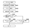
図4は、CPU310が実行するゲインカーブ選択制御のフローチャートを示す。
図4を参照して、本例の制御動作を説明すると、先ず、基準白板209(図2参照)を読取るための露光走査を行うために、基準白板209の下に第1走行体203(図2参照)を移動させる(ステップS401)。
ゲインカーブ選択制御における基準白板209の読取は、増幅回路304(図3参照)を所定ゲインで動作させるので、そのための設定を行う。本実施形態ではゲインを1倍に設定する(ステップS402)。
次に、基準白板209の読取を行い、設定ゲイン1倍で増幅回路304を動作させ、アナログ信号処理回路308から出力される基準白板データをもとに、基準白板レベル検出回路309で基準白板レベル検出を行う(ステップS403)。
次いで、検出した基準白板レベルと予め定めされている基準白板目標レベルから予想ゲインを求める(上記[0015]参照)。この予想ゲインを選択基準値に照らして、選択するゲインカーブを判定する(ステップS404)。本実施形態では、選択基準値を“5”として、予想ゲインが5以上であるか、否かを判断し、その結果によりゲインカーブ1又はゲインカーブ2を選択する。
即ち、基準白板レベルが低く、予想ゲインが5以上である場合には(ステップS404-YES)、高分解能のゲイン設定が可能なゲインカーブを選択できないので、より低分解能のゲイン設定ゲインカーブ2を選択する(ステップS405)。また、基準白板レベルが高く、予想ゲインが5未満である場合には(ステップS404-NO)、高分解能のゲイン設定が可能なゲインカーブ1を選択する(ステップS406)。
このフローに示す様な選択を行うことにより、単一のゲインカーブを用いる場合に比べて、基準白板レベルが高い場合には、極めて高い分解能が選択でき、基準白板レベルが低い場合でも、より高い分解能が選択できる。この結果、基準白板レベルの低下を抑え、レベル低下によって、増幅回路304の後段にあるAD変換回路305のダイナミックレンジが縮小し、ノイズの増加をもたらす、という問題を解消することが可能になる。
In the gain curve selection control, the process of calculating the expected gain and determining the gain curve by judging the calculation result in light of the selection reference value described in the above explanation of the principle is executed.
FIG. 4 shows a flowchart of gain curve selection control executed by the
The control operation of this example will be described with reference to FIG. 4. First, in order to perform exposure scanning for reading the reference white plate 209 (see FIG. 2), the first traveling body 203 (see FIG. 2) is moved (step S401).
The reading of the reference
Next, the reference
Next, an expected gain is obtained from the detected reference white plate level and a predetermined reference white plate target level (see [0015] above). A gain curve to be selected is determined by comparing the expected gain with the selection reference value (step S404). In the present embodiment, the selection reference value is “5”, it is determined whether or not the expected gain is 5 or more, and the
That is, when the reference white board level is low and the expected gain is 5 or more (step S404-YES), a gain curve that can set a high resolution gain cannot be selected. Select (step S405). If the reference white board level is high and the expected gain is less than 5 (NO in step S404), the
By making a selection as shown in this flow, an extremely high resolution can be selected when the reference white plate level is high compared to when a single gain curve is used, and even when the reference white plate level is low, it is higher. The resolution can be selected. As a result, it is possible to suppress the decrease in the reference white plate level and to solve the problem that the decrease in the dynamic range of the
上記実施形態では、ゲイン調整において、ゲイン設定分解能の異なる複数のゲインカーブから入力画像の信号レベルに適応したゲインカーブを選択、適用するための基本的な手段について示した。以下には、上記実施形態をベースに付加条件を考慮し、改良を加えた実施形態を示す。
ゲインカーブを選択するために、所定ゲインで基準白板レベルを読取る際に、画像ノイズが大きいシステムの場合、基準白板レベルのバラツキから予想ゲインと実際のゲインに差が発生し、誤ったゲインカーブの選択につながることが懸念される。即ち、予想ゲインと基準値を比較して、ゲインカーブ1が選択されたが、実際は5倍以上のゲインが必要であったとき、ゲインカーブ1では5倍以上のゲイン設定ができないため、基準白板目標レベルに調整できない問題が発生する。
ゲインカーブ1で調整できない場合にゲインカーブ2で再度調整する処理を行うと、調整に時間を必要とする。こうした状況にならないようにするために、エラーの原因となるノイズの影響を抑制することが必要である。本実施形態では、所定ゲインでの基準白板レベルを平均化処理することでノイズを除去し、レベルを安定させることにより、誤ったゲインカーブの選択を防ぐことを可能とする。
基準白板レベルの平均化処理としては、いろいろな方法を採用することができるが、例えば、
・ 基準白板を複数回読取った結果として得られる複数の基準白板レベルの平均
値を求めるデータとする。
・ 主走査方向に全画素の平均値を算出し、その値を求めるデータとする。
・ 主走査方向に複数画素単位で平均値を算出し、その中のピーク値を副走査方向に
数ライン分得、得たピーク値の中のmax値を求めるデータとする。
といった処理による。
上記のような平均化処理によって、基準白板レベルを安定化させることで、予想ゲインと実際のゲインの差を小さくすることが可能となり、適合するゲインカーブを誤り無く選択することが可能になる。
読取画像信号の信号処理回路(図3参照)の回路動作としては、基準白板レベル検出回路309に平均化処理機能を持たせ、ここで平均化処理を行い、得た基準白板レベル検出結果をCPU310に伝える、CPU310は、この検出結果を受けて、上記実施形態(図4参照)と同様に予想ゲインの演算を行い、増幅回路304のゲインカーブを選択することにより、所期のゲイン調整を可能とする。
In the above-described embodiment, basic means for selecting and applying a gain curve adapted to the signal level of the input image from a plurality of gain curves having different gain setting resolutions in gain adjustment has been described. In the following, an embodiment in which additional conditions are taken into consideration based on the above embodiment and improvements are shown.
When reading the reference white board level with a predetermined gain to select the gain curve, in a system with a large amount of image noise, a difference occurs between the expected gain and the actual gain due to variations in the reference white board level, and an incorrect gain curve is displayed. There is concern that it will lead to choice. That is, the
If adjustment is performed again using the
Various methods can be employed as the standard whiteboard level averaging process. For example,
・ Use the data to calculate the average value of multiple levels of the reference white plate obtained as a result of reading the reference white plate multiple times.
-Calculate the average value of all pixels in the main scanning direction and use it as the data for obtaining the value.
-Calculate the average value in the unit of multiple pixels in the main scanning direction, obtain several peak values in the sub-scanning direction, and use it as the data for obtaining the max value of the obtained peak values.
It depends on the process.
By stabilizing the reference white plate level by the averaging process as described above, the difference between the expected gain and the actual gain can be reduced, and a suitable gain curve can be selected without error.
As a circuit operation of the signal processing circuit for the read image signal (see FIG. 3), the reference white plate
画像ノイズが大きいシステムの場合、上記のように、基準白板の読取画像に対して平均化処理を行うが、平均化処理を行った場合でも、ノイズを除き切れずに画像レベルを安定化できない場合が考えられる。
こうしたケースでも、上記実施形態の記載に示したと同様に、基準白板目標レベルに調整できない場合が想定される。
例えば、予想ゲインが5倍以下の値であった場合には、ゲインカーブ1が選択される。しかし、実際のゲインが予想ゲインより高い場合(5倍以上)には、基準白板目標レベルへの調整が正常に行えない。
そこで、画像読取装置の画像ノイズから、予想ゲインと実際のゲインの差を求め、その最大値を予め想定して、ゲインカーブ1の中で使用するゲイン値を制限することで基準白板レベル調整を常に正常に行えるようにすることが可能になる。
この方法では、例えば、ゲインカーブ1で最大ゲインを4倍までの使用に制限すれば、予想ゲインが4倍以上であった場合に、ゲインカーブ2を選択する。従って、実際のゲインが5倍以上であった場合でも基準白板レベル調整は正常に行える。逆に実際のゲインが4倍以下であった場合でも、ゲインカーブ2に於いて2倍以下にならなければ基準白板調整は正常に行える。
読取画像信号の信号処理回路(図3参照)の回路動作としては、CPU310が予想ゲインの演算を行い、増幅回路304のゲインカーブを選択するが、この時の選択基準値(図4の選択ステップS404の条件式、参照)を変更することで実現可能である。例えば、上記実施形態のように、選択基準値“5”であった値を “4”に変更する等によって、所期のゲイン調整を可能とする。
In the case of a system with a large amount of image noise, the averaging process is performed on the scanned image of the reference white board as described above, but even if the averaging process is performed, the image level cannot be stabilized without removing the noise. Can be considered.
Even in such a case, the case where it cannot adjust to a reference white board target level is assumed like the description of the said embodiment.
For example, when the expected gain is a value of 5 times or less, the
Therefore, the difference between the expected gain and the actual gain is obtained from the image noise of the image reading apparatus, the maximum value is assumed in advance, and the reference white plate level adjustment is performed by limiting the gain value used in the
In this method, for example, if the maximum gain of the
As a circuit operation of the signal processing circuit for the read image signal (see FIG. 3), the
次に、ゲイン調整に要する時間の短縮化を図るための手段を示す。
例えば、カラー画像読取装置における、カラー読取モードやモノクロ読取モードのように、増幅回路304における増幅率の変更が必要となる読取モードを複数実行する機能を持つ場合には、読取モードの数だけ、ゲインカーブの選択を行う必要がある。このために、ゲイン調整に要する時間が増加してしまう。そこで以下のような手段を講じる。
カラー読取モードとモノクロ読取モードは、CCDを異なるライン周期で動作させる。この様なモード設定が可能なシステムの場合、ライン周期の切り替えにより光の蓄積時間が変わる。従って、光の蓄積時間が変わることにより同じ基準白板を読取った場合に、ゲインが同じでも、基準白板読取出力レベルが異なる。従って、基準白板目標レベルへの調整を行うためには、カラー、モノクロ読取でゲインを変える必要がある。
CCDの出力は光の蓄積時間に比例するため、どちらか一方の予想ゲインからもう一方のゲインカーブを予想することが可能となる。この関係を利用して、ゲイン選択に要する時間を短縮可能とする。
モノクロモードの場合、人間の視感度分光特性に近いカラーCCDのGreenの出力が、画像データとして使用に供される。本実施形態では、カラーCCDのGreenの予想ゲインからモノクロゲインカーブを選択するための予想ゲインを導く関係式を利用して、モノクロ読取モードのゲイン選択処理を簡易化する。
例えば、カラーのライン周期がA(S)、モノクロのライン周期がB(S)、カラーCCDのGreen出力に対する予想ゲインがC(倍)であった場合、下記関係式、即ち、
モノクロ予想ゲイン(倍)=B/A×C
で算出可能である。
このように、カラー読取における予想ゲインからモノクロモードでのゲインカーブを選択するための予想ゲインを演算することで、モノクロ読取モードにおける基準白板の読取を行わずにすませることにより、ゲイン調整に要する時間を短縮することが可能となり、全体の調整時間の短縮化が図られる。
読取画像信号の信号処理回路(図3参照)の回路動作としては、CPU310が、上記関係式によって、カラー読取モードで求めた予想ゲインからモノクロ予想ゲインを演算し、この演算結果に基づいて増幅回路304のゲインカーブを選択し、所期のゲイン調整を可能とする。
Next, means for shortening the time required for gain adjustment will be shown.
For example, when a color image reading apparatus has a function of executing a plurality of reading modes that require a change in the amplification factor in the
The color reading mode and the monochrome reading mode operate the CCD with different line periods. In the case of such a system capable of mode setting, the light accumulation time changes by switching the line cycle. Accordingly, when the same reference white plate is read by changing the light accumulation time, the reference white plate reading output level is different even if the gain is the same. Therefore, in order to adjust to the reference white plate target level, it is necessary to change the gain in color and monochrome reading.
Since the output of the CCD is proportional to the light accumulation time, it is possible to predict the other gain curve from one of the expected gains. Using this relationship, the time required for gain selection can be shortened.
In the monochrome mode, the green output of the color CCD that is close to human visibility spectral characteristics is used as image data. In the present embodiment, the gain selection process in the monochrome reading mode is simplified by using a relational expression that derives an expected gain for selecting a monochrome gain curve from the expected Green gain of the color CCD.
For example, if the color line period is A (S), the monochrome line period is B (S), and the expected gain for the green output of the color CCD is C (times),
Monochrome expected gain (times) = B / A x C
Can be calculated.
Thus, by calculating the expected gain for selecting the gain curve in the monochrome mode from the expected gain in color reading, the time required for gain adjustment can be avoided without reading the reference white plate in the monochrome reading mode. This makes it possible to shorten the overall adjustment time.
As a circuit operation of the signal processing circuit (see FIG. 3) of the read image signal, the
CCDの出力チャンネルが複数存在する、例えばカラーCCDでは、色毎に別のゲインカーブを用いることによって、増幅回路のノイズ特性、入出力のリニアリテイ特性等が異なることになると、RGB画像特性も異なってしまう、という問題が生じる。
カラー画像読取装置としては、RGB画像特性は同じ方が良い。というのは、後段で画像処理を行うが、その際RGBの画像特性が異なる場合には、画像特性に合わせた画像処理パラメータをRGB毎に用意する等の対応が必要になり、回路規模が大きくなり、パラメータ設計にも時間を要する。
そこで、RGB毎に増幅回路で選択するゲインカーブを全て同じゲインカーブとすることで、増幅回路の画像特性バラツキを排除し、後段の画像処理回路の簡易化を図るものを、次に示す。
読取画像信号の信号処理回路(図3参照)の回路動作としては、CPU310が、RGBのチャンネルの順番で、ゲインレンジの選択制御フロー(図4参照)を実行し、予想ゲインを演算し、この演算結果に基づいて増幅回路304のゲインカーブを選択し、RGB全てのチャンネルについてゲインカーブ1を選択すべき結果となった場合のみ、実際に各チャンネルについてゲインカーブ1を選択する。他方、RGB各チャンネルの中で1つでもゲインカーブ2を選択すべき結果となった場合、実際にはRGB全てのチャンネルについてゲインカーブ2を選択する制御動作を行うことにより、実現可能である。
また、上記の制御により、例えば、RGBチャンネルの順番でゲインカーブ選択を行った場合に、最初のRチャンネルでゲインカーブ2が選択された場合、残りのG、Bチャンネルは自動的にゲインカーブ2が選択されることになり、ゲインカーブ選択時間のいっそうの短縮が可能となる。
さらに、RGBチャンネルの中で最もゲインが高くなるチャンネルが予め分かっている場合には、ゲインの高いチャンネルからの順番でゲインカーブ選択を実行すればよい。上記のゲインカーブ2が選択された場合におけると同様に、ゲインカーブ選択時間を短縮し得る。
For example, in a color CCD where there are a plurality of CCD output channels, when using different gain curves for each color, the noise characteristics of the amplifier circuit, input / output linearity characteristics, etc. will differ, and the RGB image characteristics will also differ. Problem arises.
As a color image reading apparatus, the RGB image characteristics should be the same. This is because image processing is performed at a later stage, but if the RGB image characteristics are different, it is necessary to prepare for each RGB an image processing parameter that matches the image characteristics, and the circuit scale is large. Therefore, parameter design also takes time.
In view of this, a gain curve selected by the amplifier circuit for each RGB is set to the same gain curve, thereby eliminating the image characteristic variation of the amplifier circuit and simplifying the subsequent image processing circuit.
As a circuit operation of the read image signal processing circuit (see FIG. 3), the
Also, with the above control, for example, when gain curve selection is performed in the order of RGB channels, if
Furthermore, when the channel with the highest gain among the RGB channels is known in advance, the gain curve selection may be executed in the order from the channel with the highest gain. Similarly to the case where the
次に示す実施形態は、上記した画像読取装置から出力される画像データに基づいて画像を形成する装置に係わるものである。なお、以下に示す実施形態は、画像形成装置としてのDPPC(Digital Plane Paper Copy-machine、所謂、デジタル複写機)への適用例を示すものである。
原稿画像の読取部を除く他の部分は、基本的には、既知のDPPCが有する構成要素を備える。図5は、本実施形態に係わるDPPCの全体構成を概略図として示す。
図5を参照して、本実施形態のDPPCの構成を説明すると、DPPC1の装置本体2には、上記実施形態に示した画像読取装置に相当するスキャナ部3(図2に対応)とスキャナ部3からの画像データを用いて印刷出力を行うプリンタ部4とを備える。なお、ここでは、スキャナ部3に原稿搬送機構であるADF(Automatic Document Feeder)ユニット5を連結する。
スキャナ部3は原稿が載置されるコンタクトガラス6を有しており、コンタクトガラス6を挟んで原稿面と対向する位置に、原稿からの光を直角に偏向する第1ミラー8と、前記第1ミラー8からの反射光路を折り返す第2ミラー9を設ける。さらに第2ミラー9からの反射光路上に、結像レンズを介して伝達される画像を光電変換するイメージセンサとしてのCCDラインイメージセンサ10が設置されている。CCDイメージセンサ10は、結像された画像をセンサ画素によりライン方向に主走査(図5面に垂直な方向)しながら画像信号に変換する。また、スキャナ部3では、原稿以外に基準白板25の読取を行う。基準白板25はスキャナに対してコピー原稿と同じ条件で読取ができるような位置に設ける。基準白板25の読取データは、読取画像データに対するシェーディングデータとして用いるために、又上記実施形態に示したゲインレンジの選択制御における基準白板レベル信号として用いられる。
The following embodiment relates to an apparatus that forms an image based on image data output from the above-described image reading apparatus. The following embodiment shows an application example to a DPPC (Digital Plane Paper Copy-machine, so-called digital copying machine) as an image forming apparatus.
The other parts excluding the document image reading unit basically include components included in a known DPPC. FIG. 5 is a schematic diagram showing the overall configuration of the DPPC according to this embodiment.
The configuration of the DPPC of this embodiment will be described with reference to FIG. 5. The apparatus
The
装置全体の制御を司る制御部7は、上記実施形態に示した画像読取装置の信号処理回路(図3、参照)に相当する回路を備え、CCDイメージセンサ10によって読取られた画像信号を正規化し、印刷出力等に利用し得る画像データとして、補正、変換といった処理を施す。ここでは、信号処理回路におけるアナログ画像信号の増幅回路で、上記実施形態に示した入力画像に適応するゲインレンジを選択する制御を行う。
また、制御部7は、読取画像を処理して得た画像データをレーザダイオード:LD による光書き込みに用いるビデオ信号として光書き込み部14へ出力する。プリンタ部4は感光ドラム11を有しており、この感光ドラム11の外周上にトナークリーナ12、帯電器13、現像器15、転写器16を順次ドラム面に対向配置する。プリンタ部4に設けた感光ドラム11は帯電器13により帯電され、帯電された感光ドラム11に書き込み部14から画像情報を担うレーザ光が照射され、感光ドラム11の表面に静電潜像を形成する。現像器15にはトナーが収納されており、静電潜像が形成された感光ドラム11表面にトナーを付着させ、静電潜像をトナー像として顕在化させる。給紙部は大容量の用紙カセット19、異なるサイズの少容量の用紙を入れるカセット17の複数種類のカセットからそれぞれ排紙トレー18まで印刷用紙を順次搬送する用紙搬送機構を設け、その用紙搬送路20は感光ドラム11と転写器16との間隙と定着器21の内部とに連通している。転写器16において、用紙搬送機構19により搬送された印刷用紙に対し、感光ドラム11に形成されたトナー像を転写させる。トナー像が転写された印刷用紙は、前記用紙搬送機構によって定着器21に搬送し、トナー像を印刷用紙に定着し、画像データが印刷された印刷用紙を排紙トレー18に排紙する。
The
Further, the
スキャナ部3のADFユニット5にコピー原稿が載置され、図示しない操作部からコピーのスタートボタンが押されると、制御部7は、原稿画像の読取、読取入力された画像信号の処理、処理後の画像データを用いた画像形成、といった一連のコピー出力処理に必要な制御を実行する。
一連のコピー出力処理の制御フローでは、入力画像に適応するゲインレンジを選択する制御を上記実施形態にそれぞれ示した形態で実行することにより、デジタル複写機上で読取画像信号処理の最適化を達成することが可能になり、デジタル複写機の高パフォーマンス化を図ることができる。
なお、本実施形態では、デジタル複写機への適用を例示したが、ファクシミリ装置等の画像読取装置から出力される画像データを用いて画像を形成する他の画像形成装置へ適用し、実施することも可能である。
When a copy document is placed on the
In the control flow of a series of copy output processing, optimization of the read image signal processing is achieved on the digital copying machine by executing the control for selecting the gain range adapted to the input image in the form shown in the above embodiment. It is possible to improve the performance of the digital copying machine.
In this embodiment, the application to a digital copying machine is exemplified, but the present invention is applied to another image forming apparatus that forms an image using image data output from an image reading apparatus such as a facsimile machine. Is also possible.
1・・DPPC(デジタル複写機)、 3・・スキャナ部、
4・・プリンタ部、 6,201・・コンタクトガラス、
7・・制御部、 10,206,301・・CCDラインイメージセンサ、
25,209・・基準白板、 207・・光源、
304・・増幅回路、 305・・AD変換回路、
309・・基準白板レベル検出回路、 310・・CPU。
1. ・ DPPC (Digital copier), 3. ・ Scanner part,
4. ・ Printer part, 6,201 ・ ・ Contact glass,
7. Control unit, 10, 206, 301 ... CCD line image sensor,
25, 209 ... Standard white plate, 207 ... Light source,
304 .. Amplification circuit, 305 .. AD conversion circuit,
309... Reference white plate
Claims (8)
前記光電変換手段が複数の読取モードに従って動作を変更する手段であり、
前記ゲインカーブの選択手段は、複数の読取モード中の1つの読取モードにおいて、前記基準読取信号レベルの基準読取信号目標レベルに対する量的関係を求め、得た量的関係に基づいて、そのモードにおけるゲインカーブを選択する第1の処理と、第1の処理により得られた前記量的関係と他の読取モードの量的関係との間で成り立つ所定の関係式に基づいて他の読取モードの量的関係を求め、得た量的関係に基づいて他の読取モードにおけるゲインカーブを選択する第2の処理を行うことにより、各読取モードのゲインカーブを選択する手段であることを特徴とする画像読取装置。 Image to be read photoelectrically converted, the photoelectric conversion means for outputting an image signal, and the gain variable amplifying means for amplifying said image signal, and control means for controlling a gain of the amplifying means, the reference reading target Means for selecting one of a plurality of gain curves each having a different gain setting resolution based on a reference read signal level obtained by photoelectric conversion by a photoelectric conversion means and amplification by a predetermined gain by the amplification means; An image reading apparatus in which the control means obtains a set value for amplifying a read signal to be read to a reference level to a target level from a gain curve selected by the selection means, and sets the obtained value in the amplification means. ,
The photoelectric conversion means is a means for changing the operation according to a plurality of reading modes,
The gain curve selection means obtains a quantitative relationship between the reference read signal level and a reference read signal target level in one reading mode among a plurality of reading modes, and based on the obtained quantitative relationship, The amount of another reading mode based on a predetermined relational expression established between the first processing for selecting a gain curve and the quantitative relationship obtained by the first processing and the quantitative relationship of another reading mode An image characterized by being a means for selecting a gain curve in each reading mode by performing a second process of selecting a gain curve in another reading mode based on the obtained quantitative relationship. Reader.
Priority Applications (1)
| Application Number | Priority Date | Filing Date | Title |
|---|---|---|---|
| JP2004273374A JP4401265B2 (en) | 2004-09-21 | 2004-09-21 | Image reading apparatus and image forming apparatus |
Applications Claiming Priority (1)
| Application Number | Priority Date | Filing Date | Title |
|---|---|---|---|
| JP2004273374A JP4401265B2 (en) | 2004-09-21 | 2004-09-21 | Image reading apparatus and image forming apparatus |
Publications (2)
| Publication Number | Publication Date |
|---|---|
| JP2006093811A JP2006093811A (en) | 2006-04-06 |
| JP4401265B2 true JP4401265B2 (en) | 2010-01-20 |
Family
ID=36234405
Family Applications (1)
| Application Number | Title | Priority Date | Filing Date |
|---|---|---|---|
| JP2004273374A Expired - Fee Related JP4401265B2 (en) | 2004-09-21 | 2004-09-21 | Image reading apparatus and image forming apparatus |
Country Status (1)
| Country | Link |
|---|---|
| JP (1) | JP4401265B2 (en) |
-
2004
- 2004-09-21 JP JP2004273374A patent/JP4401265B2/en not_active Expired - Fee Related
Also Published As
| Publication number | Publication date |
|---|---|
| JP2006093811A (en) | 2006-04-06 |
Similar Documents
| Publication | Publication Date | Title |
|---|---|---|
| US11265424B2 (en) | Image forming apparatus | |
| US7433088B2 (en) | Reference white plate density data adjusting image reading and forming apparatus | |
| US9179030B2 (en) | Image reading device, image forming apparatus, and image reading method | |
| US8804208B2 (en) | Image reading apparatus | |
| EP1615421B1 (en) | Image scanner | |
| JP5533230B2 (en) | Image reading apparatus and image forming apparatus | |
| JP4401265B2 (en) | Image reading apparatus and image forming apparatus | |
| JP4127603B2 (en) | Image reading apparatus, image forming apparatus, and read image data processing method | |
| JP4928597B2 (en) | Image reading apparatus, image processing apparatus, image forming apparatus, system thereof, and control method thereof | |
| US9516287B2 (en) | Imaging device, image reading device, image forming apparatus, and method of driving imaging device | |
| JP4246932B2 (en) | Image reading apparatus and image forming apparatus | |
| JP2001217995A (en) | Image reader | |
| JP2012151644A (en) | Image reader, image formation apparatus provided with image reader, and image processing method | |
| JP4070026B2 (en) | Image processing apparatus and program used for the same | |
| JP2003101772A (en) | Image reading equipment and image forming equipment | |
| JP2002271627A (en) | Image reader, imaging device and read image data processing method | |
| JP2010220076A (en) | Image-reading apparatus, image forming apparatus, shading correction method, and shading correction control program | |
| JP5895336B2 (en) | Image reading apparatus and image forming apparatus | |
| JP2010021727A (en) | Image reading device and control method thereof | |
| JP2005269179A (en) | Image reading apparatus | |
| JP2010246125A (en) | Image reading apparatus, image processing apparatus and control method thereof | |
| JP2007282127A (en) | Image reading apparatus and image forming apparatus | |
| JP2008271396A (en) | Image reading apparatus, and density correcting method thereof | |
| JP2007213439A (en) | Image reader and image forming apparatus | |
| JP2017198972A (en) | Image forming apparatus and control method |
Legal Events
| Date | Code | Title | Description |
|---|---|---|---|
| A621 | Written request for application examination |
Free format text: JAPANESE INTERMEDIATE CODE: A621 Effective date: 20070126 |
|
| A131 | Notification of reasons for refusal |
Free format text: JAPANESE INTERMEDIATE CODE: A131 Effective date: 20090701 |
|
| A521 | Written amendment |
Free format text: JAPANESE INTERMEDIATE CODE: A523 Effective date: 20090827 |
|
| TRDD | Decision of grant or rejection written | ||
| A01 | Written decision to grant a patent or to grant a registration (utility model) |
Free format text: JAPANESE INTERMEDIATE CODE: A01 Effective date: 20091027 |
|
| A01 | Written decision to grant a patent or to grant a registration (utility model) |
Free format text: JAPANESE INTERMEDIATE CODE: A01 |
|
| A61 | First payment of annual fees (during grant procedure) |
Free format text: JAPANESE INTERMEDIATE CODE: A61 Effective date: 20091027 |
|
| R150 | Certificate of patent or registration of utility model |
Ref document number: 4401265 Country of ref document: JP Free format text: JAPANESE INTERMEDIATE CODE: R150 Free format text: JAPANESE INTERMEDIATE CODE: R150 |
|
| FPAY | Renewal fee payment (event date is renewal date of database) |
Free format text: PAYMENT UNTIL: 20121106 Year of fee payment: 3 |
|
| FPAY | Renewal fee payment (event date is renewal date of database) |
Free format text: PAYMENT UNTIL: 20131106 Year of fee payment: 4 |
|
| LAPS | Cancellation because of no payment of annual fees |