JP4401034B2 - Caliper body for disc brakes for vehicles - Google Patents
Caliper body for disc brakes for vehicles Download PDFInfo
- Publication number
- JP4401034B2 JP4401034B2 JP2001083753A JP2001083753A JP4401034B2 JP 4401034 B2 JP4401034 B2 JP 4401034B2 JP 2001083753 A JP2001083753 A JP 2001083753A JP 2001083753 A JP2001083753 A JP 2001083753A JP 4401034 B2 JP4401034 B2 JP 4401034B2
- Authority
- JP
- Japan
- Prior art keywords
- action
- disk
- bridge
- caliper body
- bridge portion
- Prior art date
- Legal status (The legal status is an assumption and is not a legal conclusion. Google has not performed a legal analysis and makes no representation as to the accuracy of the status listed.)
- Expired - Fee Related
Links
Images
Landscapes
- Braking Arrangements (AREA)
Description
【0001】
【発明の属する技術分野】
本発明は、自動車や自動二・三輪車等の走行車両に搭載されるディスクブレーキのキャリパボディに関する。
【0002】
【従来の技術】
自動二・三輪車等に搭載されるディスクブレーキのキャリパボディとして、例えば登録意匠第1025215号に示されるものがある。
このキャリパボディは、ディスクロータの両側部に配設される一対の作用部と、ディスクロータの外周を跨いでこれらをつなぐブリッジ部とを一体形成しており、さらに車体取り付け側となる一方の作用部には、フロントフォークやスイングアーム等の車輪懸架部材に取り付けするためのブラケットが一体に形成されている。
【0003】
ブリッジ部の中央部には矩形の天井開口部が形成されていて、双方の作用部の間にディスクロータを挟んで対向配置される一対の摩擦パッドを抜き差しできるようにしている。各作用部のディスクロータ側面には、ピストンを収容するシリンダ孔が開口しており、該開口を挟んだディスク回入側及び回出側にトルク受け部があって、制動時にディスクロータに引き摺られる摩擦パッドの側面をこのトルク受け部で支承するようになっている。
【0004】
ブリッジ部のディスク内周側は、ディスクロータの回転中心を支点とする円弧面に形成されていて、上述の4つのトルク受け部はこのブリッジ部のディスク内周側に達するように設けられており、さらにこれら4つのトルク受け部の間に挟まれたブリッジ部のディスク内周側中央にはロータ溝が凹設されていて、このロータ溝にディスクロータが回転可能に収容されるようになっている。
【0005】
【発明が解決しようとする課題】
このようなキャリパボディを車輪懸架部材に取り付けして制動作用を行うと、ディスクロータからの制動反力が摩擦パッドを通して双方の作用部に作用し、該作用部を反ディスク方向へ押し戻す。各作用部の変形はブリッジ部へも影響し、ブリッジ部のディスク内側には引っ張り荷重を、またディスク外側には圧縮荷重をそれぞれ生じて、キャリパボディは全体としてブリッジ部を支点にハの字状に変形する。
【0006】
このため、ディスク軸と平行であった作用部内のシリンダ孔とこのシリンダ孔に収容されるピストンとが傾き、さらに摩擦パッドも一体に傾いて、摩擦パッドのライニングのディスク外側が偏摩耗することとなる。このようなライニングの偏摩耗は、キャリパボディの構造上やむを得ないが、一方の作用部側では車輪懸架部材の支持剛性力が作用して傾きが比較的小さく抑えられるためにライニングの偏摩耗が少ないのに対し、車輪懸架部材に支持されない他方の作用部側で傾きが大きくなってはライニングの偏摩耗が早くなり、パッド交換を早期に摩耗するものに合わせて行ったり、交換作業を別々に行ったりする必要があった。
【0007】
本発明は、かかる実情を背景にしてなされたもので、その目的とするところは、キャリパボディに用いる一対の摩擦パッドのライニングが極力同程度に摩耗するようにし、併せてキャリパボディを軽量化して低コスト化と車体ばね下荷重の軽減を図ることのできる車両用ディスクブレーキのキャリパボディを提供することにある。
【0008】
【課題を解決するための手段】
本発明は、上述の目的を達成するため、第1発明では、ディスクロータの両側部に配設される一対の作用部を、ディスクロータの外周を跨いで配設されるブリッジ部にて一体に連結し、前記一対の作用部のいずれか一方を車体に支持される車両用ディスクブレーキのキャリパボディにおいて、前記ブリッジ部のディスク内周側に、前記ディスクロータの厚さ等分線を挟んで凹部を形成し、前記他方の作用部側の凹部外側のブリッジ部を、前記一方の作用部側の凹部外側のブリッジ部よりも厚肉とする。
【0009】
また第2発明では、ディスクロータの両側部に配設される一対の作用部を、ディスクロータの外周を跨いで配設されるブリッジ部にて一体に連結し、前記一対の作用部のいずれか一方を車体に支持される車両用ディスクブレーキのキャリパボディにおいて、前記ブリッジ部のディスク内周側に、前記ディスクロータの厚さ等分線を挟んで凹部を形成すると共に、該厚さ等分線から前記一方の作用部側の凹部を、他方の作用部側の凹部よりも大きく形成し、前記他方の作用部側の凹部外側のブリッジ部を、前記一方の作用部側の凹部外側のブリッジ部よりも厚肉とする。
【0010】
双方の作用部が、ディスクロータからの制動反力によって反ディスクロータ側へ変形しようとする場合に、ブリッジ部の剛性力が抗力として作用するが、作用部の変形に対するブリッジ部の抗力は、圧縮力が作用するディスク外側が主として担っており、引っ張り力が作用するディスク内側は抗力としてさほど期待できない。
【0011】
そこで本発明は、作用部変形の抗力として効果の少ないブリッジ部のディスク内側部分に凹部を形成することによって軽量化を図り、また凹部の外側では、反車体取り付け側のブリッジ部の肉厚を車体取り付け側のブリッジ部の肉厚よりも厚くすることによって、双方の作用部の剛性力が略同一となるようにしている。この結果、制動反力による双方の作用部の開き変形が略同一となり、摩擦パッドのライニングが同程度に摩耗することになる。
【0012】
【発明の実施の形態】
以下、本発明のキャリパボディを自動二輪車等のバーハンドル車両のフロントディスクブレーキに適用した形態例を図面に基づいて説明する。
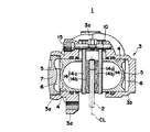
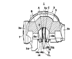
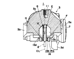
図中、図1〜図7は、第1形態例を示し、図1はディスクブレーキの底面図、図2はディスクブレーキの正面図、図3はディスクブレーキの平面図、図4は図3のIV−IV断面図、図5は図2のV−V断面図、図6は図2のVI−VI断面図、図7は図2のVII−VII断面図である。
【0013】
第1形態例のフロントディスクブレーキ1は、フロントフォークの下端に支承される車輪(いずれも図示せず)の一側部に、ディスクロータ2が車輪と矢印R方向へ一体回転可能に取り付けされ、該ディスクロータ2を跨いで配設されるキャリパボディ3が、一方の作用部3aのディスク内側と回出側とに設けられたブラケット3d,3eを、フロントフォークの下端近傍にボルト止めして取り付けするようになっている。
【0014】
上記キャリパボディ3は、ディスクロータ2の両側部に配設される一対の作用部3a,3bと、ディスクロータ2の外周を跨いでこれらをつなぐブリッジ部3cとを一体に成形し、作用部3a,3bにそれぞれ大小2個づつのシリンダ孔4をディスク周方向に対向して設け、これらシリンダ孔4に大径または小径のピストン5をそれぞれ収容したモノコックタイプの4ポットピストン対向型に形成されている。
【0015】
各ピストン5は、作用部3a,3bのディスクロータ側面に開口して設けられた上述のシリンダ孔4にそれぞれ液密且つ移動可能に内挿され、該シリンダ孔4とピストン5の底壁間に液圧室6が画成されている。作用部3a,3bのシリンダ孔4,4は、キャリパボディ3の鋳造成形後に一方の作用部3a側から加工具を差し込んで素孔を仕上げ加工するため、この仕上げ加工後に作用部3aのシリンダ孔4開口部に別途のキャップ7を被着してその底壁となしている。
【0016】
作用部3a,3bのディスクロータ側面それぞれには、一対のトルク受け部3f,3gがシリンダ孔4,4の開口部を挟んだディスク回入側と回出側に突設されており、ブリッジ部3cの中央部に、天井開口部10が内外に貫通して設けられると共に、ブリッジ部3cのディスク回出側外側にユニオン孔11が穿設されている。
【0017】
ブリッジ部3cのディスク内周側は、天井開口部10の形成によってディスク回入側と回出側に分断されており、その中央部にディスクロータ2を収容する円弧状のロータ溝12が凹設されると共に、ロータ溝12の両側部に4つの凹部13a,13b,13c,13dが連続して設けられている。凹部13a〜13dのうち、ディスクロータ2の厚さ等分線CLを挟んだディスク回入側の2つの凹部13a,13bが対称形に形成され(図6参照)、同じく厚さ等分線CLを挟んだディスク回出側の2つの凹部13c,13dが対称形に形成されている(図7参照)。
【0018】
また、ブリッジ部3cのディスク回入側と回出側の外形状は、凹部13a〜13dの外側において、他方の作用部3b側が一方の作用部3a側よりも外側に膨らんだ非対称形状となっている。この結果、ブリッジ部3cのディスク回入側では(図6参照)、他方の作用部3b側の凹部13b外側の境界線C,D間が、一方の作用部3a側の凹部13a外側の境界線A,B間よりも厚肉に、またブリッジ部の3cのディスク回出側では(図7参照)、他方の作用部3b側の凹部13d外側の境界線G,H間が、一方の作用部3a側の凹部13c外側の境界線E,F間よりも厚肉となっており、これによって、厚さ等分線CLを挟んだブリッジ部3cの一方の作用部3a側と他方の作用部3b側の剛性力が略同一となるようにしている。
【0019】
前記天井開口部10は、ディスクロータ2の両側部に一対の摩擦パッド14,14を抜き差しできる大きさの矩形に、また作用部3a,3bのトルク受け部3f,3gは、摩擦パッド14の裏板14aを収容できる間隔にそれぞれ形成されており、摩擦パッド14,14は、天井開口部10内を貫通してブリッジ部3cにディスク軸方向へ架設されるハンガーピン15,15を裏板14aの上部に挿通し、裏板14aをトルク受け部3f,3gに収容して、作用部3a,3bのディスクロータ2側面とディスクロータ2との間にディスク軸方向へ移動可能に吊持される。
【0020】
前記ユニオン孔11は、キャリパボディ3の内部で4つの液圧室6に連通しており、ライダーの制動操作によって別途の図示しない液圧マスタシリンダで昇圧された作動液は、ユニオン孔11を通して各液圧室6へ供給される。液圧室6へ供給された作動液は、それぞれのピストン5をシリンダ孔4の開口部方向へ押動し、さらにピストン5が摩擦パッド14,14をディスクロータ2方向へ押動して、摩擦パッド14,14のライニング14b,14bをディスクロータ2の側面に摺接させて制動作用が行われる。
【0021】
このように制動作用が行われると、ディスクロータ2からの制動反力が摩擦パッド14,14を通して双方の作用部3a,3bに作用し、該作用部3a,3bを反ディスク方向へ押し戻して、ブリッジ部3cを支点にキャリパボディ3の全体をハの字状に変形させようとするが、本形態例では、他方の作用部3bの凹部13b,3d外側のブリッジ部3cを、作用部3aの凹部13a,3c外側のブリッジ部3cよりも厚く形成して、厚さ等分線CLを挟んだブリッジ部3cの一方の作用部3a側と他方の作用部3bの剛性力が略同一となるようにしたから、制動反力による作用部3a,3bの変形は略同様になる。
【0022】
この結果、双方の作用部3a,3bのライニング14b,14bの摩耗程度が略同様になるので、摩擦パッド14,14を同時に交換することができるようになり、作業性と経済性を向上することができる。また、ハの字変形の抗力としてあまり期待できないブリッジ部3cのディスク内側では、凹部13a〜13dの形成によってキャリパボディ3が軽量となるので、材料費の節減によるコストダウンと、軽量化による車体ばね下荷重の軽減とが図れる。
【0023】
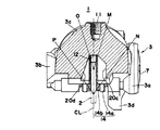
図8〜図10は、本発明の第2形態例を示すもので、上述の第1形態例では、ブリッジ部3cのディスク内側の凹部13a〜13dが、厚さ等分線CLを挟んで対称に位置するのに対し、本形態例は、一方の作用部3a側の凹部20a,20cと他方の作用部3b側の凹部20b,20dとを非対称形状とした点で第1形態例と異なっている。
【0024】
即ち、ブリッジ部3cのディスク回入側では、ディスクロータ2の厚さ等分線CLを挟んで、一方の作用部3a側の凹部20aが他方の作用部3b側の凹部20bよりも大きく形成され、またブリッジ部3cのディスク回出側では、同じく厚さ等分線CLを挟んで、一方の作用部3a側の凹部20cが他方の作用部3b側の凹部20dよりも大きく形成されている。
【0025】
また、ブリッジ部3cのディスク回入側と回出側の外形状は、第1形態例と同様に、他方の作用部3b側が一方の作用部3a側よりも外側に膨らんだ非対称形状となっている。
【0026】
この結果、ブリッジ部3cのディスク回入側では(図9参照)、他方の作用部3b側の凹部20b外側の境界線K,L間が、一方の作用部3a側の凹部20a外側の境界線I,J間よりも厚肉に、またブリッジ部の3cのディスク回出側では(図10参照)、他方の作用部3b側の凹部13d外側の境界線O,P間が、一方の作用部3a側の凹部13c外側の境界線M,N間よりも厚肉となっており、これによって、厚さ等分線CLを挟んだブリッジ部3cの一方の作用部3a側と他方の作用部3b側の剛性力が略同一となるようにしている。
【0027】
【発明の効果】
以上説明したように、本発明の車両用ディスクブレーキのキャリパボディによれば、ブリッジ部の双方の作用部の剛性力を略同じにすることができるので、制動反力による作用部の変形にも、双方の作用部のライニングが略同程度に摩耗するようになり、摩擦パッドを同時に交換することができるので、作業性と経済性の向上が図れる。また、ハの字変形の抗力としてあまり期待できないブリッジ部のディスク内側では、凹部の形成によってキャリパボディが軽量となるので、材料費の節減によるコストダウンと、軽量化による車体ばね下荷重の軽減とが図れる。
【図面の簡単な説明】
【図1】 本発明の第1形態例を示すフロントディスクブレーキの底面図
【図2】 本発明の第1形態例を示すフロントディスクブレーキの正面図
【図3】 本発明の第1形態例を示すフロントディスクブレーキの平面図
【図4】 本発明の第1形態例を示す図2のIV−IV断面図
【図5】 本発明の第1形態例を示す図3のV−V断面図
【図6】 本発明の第1形態例を示す図2のVI−VI断面図
【図7】 本発明の第1形態例を示す図2のVII−VII断面図
【図8】 本発明の第2形態例を示すフロントディスクブレーキの底面図
【図9】 本発明の第2形態例を示す図8のIX−IX断面図
【図10】 本発明の第2形態例を示す図8のX−X断面図
【符号の説明】
1…フロントディスクブレーキ、2…ディスクロータ、3…キャリパボディ、3a…車体取り付け側となる一方の作用部。3b…反車体取り付け側となる他方の作用部、3c…ブリッジ部、4…シリンダ孔、5…ピストン、6…液圧室、10…天井開口部、12…ロータ溝、3f,3g…トルク受け部、13a,13c…一方の作用部3a側の凹部、13b,13d…他方の作用部3b側の凹部、14…摩擦パッド、14a…裏板、14b…ライニング、20a,20c…一方の作用部3a側の凹部、20b,20d…他方の作用部3b側の凹部、L…ディスクロータ2の回転方向、CL…ディスクロータ2の厚さ等分線[0001]
BACKGROUND OF THE INVENTION
The present invention relates to a caliper body for a disc brake mounted on a traveling vehicle such as an automobile or a motorcycle or a tricycle.
[0002]
[Prior art]
An example of a caliper body for a disc brake mounted on a motorcycle or a tricycle is shown in, for example, registered design No. 1025215.
This caliper body is integrally formed with a pair of action parts disposed on both sides of the disk rotor and a bridge part that connects the action parts across the outer periphery of the disk rotor. The part is integrally formed with a bracket for attaching to a wheel suspension member such as a front fork or a swing arm.
[0003]
A rectangular ceiling opening is formed in the central portion of the bridge portion so that a pair of friction pads disposed opposite to each other with a disk rotor interposed between both action portions can be inserted and removed. A cylinder hole that accommodates the piston is opened on the side of the disk rotor of each working part, and there are torque receiving parts on the disk inlet side and outlet side across the opening, and dragged by the disk rotor during braking. The side surface of the friction pad is supported by the torque receiving portion.
[0004]
The disk inner periphery side of the bridge portion is formed in an arc surface with the rotation center of the disk rotor as a fulcrum, and the above four torque receiving portions are provided so as to reach the disk inner periphery side of the bridge portion. In addition, a rotor groove is formed in the center of the disk inner peripheral side of the bridge portion sandwiched between these four torque receiving portions, and the disk rotor is rotatably accommodated in the rotor groove. Yes.
[0005]
[Problems to be solved by the invention]
When such a caliper body is attached to the wheel suspension member to perform a braking action, a braking reaction force from the disk rotor acts on both acting parts through the friction pad, and pushes the acting part back in the anti-disk direction. The deformation of each action part also affects the bridge part. A tensile load is generated on the inside of the disk of the bridge part and a compressive load is generated on the outside of the disk. The caliper body as a whole has a square shape with the bridge part as a fulcrum. Transforms into
[0006]
For this reason, the cylinder hole in the working part parallel to the disk shaft and the piston accommodated in the cylinder hole are inclined, and the friction pad is also inclined integrally, and the disk outer side of the friction pad lining is unevenly worn. Become. Such uneven wear of the lining is unavoidable due to the structure of the caliper body, but since the support rigidity force of the wheel suspension member acts on one working part side and the inclination is kept relatively small, the uneven wear of the lining is small. On the other hand, if the inclination on the other side of the working part that is not supported by the wheel suspension member is increased, uneven wear of the lining will be accelerated, so that the pad should be replaced according to what is worn earlier, or the replacement work should be performed separately. It was necessary to do.
[0007]
The present invention has been made in the background of such circumstances, and the purpose of the present invention is to make the lining of a pair of friction pads used for the caliper body wear as much as possible, and to reduce the weight of the caliper body. An object of the present invention is to provide a caliper body for a disc brake for a vehicle that can reduce the cost and reduce the unsprung body load.
[0008]
[Means for Solving the Problems]
In order to achieve the above object, according to the first aspect of the present invention, in the first aspect of the invention, the pair of action portions disposed on both sides of the disk rotor are integrated with a bridge portion disposed across the outer periphery of the disk rotor. A caliper body of a vehicle disc brake that is coupled and supported by one of the pair of action portions on a vehicle body, and has a concave portion on a disc inner periphery side of the bridge portion with a thickness dividing line of the disc rotor interposed therebetween. And the bridge portion outside the recess on the other action portion side is thicker than the bridge portion outside the recess on the one action portion side.
[0009]
In the second invention, the pair of action portions disposed on both sides of the disk rotor are integrally connected by a bridge portion disposed across the outer periphery of the disk rotor, and one of the pair of action portions. In the caliper body of the disc brake for a vehicle, one of which is supported by the vehicle body, a recess is formed on the disc inner peripheral side of the bridge portion with the thickness equipartition line of the disc rotor interposed therebetween, and the thickness equipartition line The concave portion on the one working portion side is formed larger than the concave portion on the other working portion side, and the bridge portion outside the concave portion on the other working portion side is formed as a bridge portion on the outside of the concave portion on the one working portion side. Be thicker than.
[0010]
When both acting parts are deformed to the anti-disk rotor side by the braking reaction force from the disk rotor, the rigidity of the bridge acts as a drag, but the drag of the bridge against the deformation of the action is a compression The outer side of the disk on which the force acts is mainly responsible, and the inner side of the disk on which the tensile force acts cannot be expected as much as a drag force.
[0011]
Therefore, the present invention reduces the weight by forming a recess in the inner part of the disk of the bridge part, which is less effective as a resistance against deformation of the action part, and the thickness of the bridge part on the side opposite to the vehicle body is reduced outside the recess. By making it thicker than the thickness of the bridge portion on the attachment side, the rigidity force of both action portions is made substantially the same. As a result, the opening deformations of both acting portions due to the braking reaction force are substantially the same, and the lining of the friction pad is worn to the same extent.
[0012]
DETAILED DESCRIPTION OF THE INVENTION
Hereinafter, an embodiment in which the caliper body of the present invention is applied to a front disc brake of a bar handle vehicle such as a motorcycle will be described with reference to the drawings.
1 to 7 show a first embodiment, FIG. 1 is a bottom view of a disc brake, FIG. 2 is a front view of the disc brake, FIG. 3 is a plan view of the disc brake, and FIG. FIG. 5 is a cross-sectional view taken along line VV in FIG. 2, FIG. 6 is a cross-sectional view taken along line VI-VI in FIG. 2, and FIG. 7 is a cross-sectional view taken along line VII-VII in FIG.
[0013]
The
[0014]
The
[0015]
Each piston 5 is inserted in the above-described
[0016]
A pair of
[0017]
The disk inner peripheral side of the
[0018]
Further, the outer shape of the
[0019]
The
[0020]
The union hole 11 communicates with the four
[0021]
When the braking action is performed in this way, the braking reaction force from the
[0022]
As a result, since the wear levels of the
[0023]
8 to 10 show a second embodiment of the present invention. In the first embodiment described above, the
[0024]
That is, on the disk entry side of the
[0025]
Further, the outer shape of the
[0026]
As a result, on the disk entry side of the
[0027]
【The invention's effect】
As described above, according to the caliper body of the vehicle disc brake of the present invention, the acting force of both acting portions of the bridge portion can be made substantially the same, so that the acting portion can be deformed by the braking reaction force. The linings of both working parts are worn to substantially the same extent, and the friction pads can be replaced at the same time, so that workability and economy can be improved. In addition, the caliper body becomes lighter due to the formation of the recess inside the disk of the bridge part which can not be expected as much resistance to the C-shaped deformation, so the cost can be reduced by reducing the material cost and the unsprung body load can be reduced Can be planned.
[Brief description of the drawings]
FIG. 1 is a bottom view of a front disc brake showing a first embodiment of the present invention. FIG. 2 is a front view of a front disc brake showing a first embodiment of the present invention. FIG. 4 is a cross-sectional view taken along the line IV-IV in FIG. 2 showing the first embodiment of the present invention. FIG. 5 is a cross-sectional view taken along the line VV in FIG. 3 showing the first embodiment of the present invention. 6 is a sectional view taken along the line VI-VI in FIG. 2 showing a first embodiment of the present invention. FIG. 7 is a sectional view taken along the line VII-VII in FIG. 2 showing a first embodiment of the present invention. FIG. 9 is a bottom view of a front disc brake showing an embodiment. FIG. 9 is a sectional view taken along the line IX-IX in FIG. 8 showing a second embodiment of the present invention. Sectional view [Explanation of symbols]
DESCRIPTION OF
Claims (2)
Priority Applications (1)
| Application Number | Priority Date | Filing Date | Title |
|---|---|---|---|
| JP2001083753A JP4401034B2 (en) | 2001-03-22 | 2001-03-22 | Caliper body for disc brakes for vehicles |
Applications Claiming Priority (1)
| Application Number | Priority Date | Filing Date | Title |
|---|---|---|---|
| JP2001083753A JP4401034B2 (en) | 2001-03-22 | 2001-03-22 | Caliper body for disc brakes for vehicles |
Publications (2)
| Publication Number | Publication Date |
|---|---|
| JP2002286062A JP2002286062A (en) | 2002-10-03 |
| JP4401034B2 true JP4401034B2 (en) | 2010-01-20 |
Family
ID=18939532
Family Applications (1)
| Application Number | Title | Priority Date | Filing Date |
|---|---|---|---|
| JP2001083753A Expired - Fee Related JP4401034B2 (en) | 2001-03-22 | 2001-03-22 | Caliper body for disc brakes for vehicles |
Country Status (1)
| Country | Link |
|---|---|
| JP (1) | JP4401034B2 (en) |
Families Citing this family (1)
| Publication number | Priority date | Publication date | Assignee | Title |
|---|---|---|---|---|
| WO2020189356A1 (en) * | 2019-03-19 | 2020-09-24 | 日信工業株式会社 | Caliper body for vehicle disc brake |
-
2001
- 2001-03-22 JP JP2001083753A patent/JP4401034B2/en not_active Expired - Fee Related
Also Published As
| Publication number | Publication date |
|---|---|
| JP2002286062A (en) | 2002-10-03 |
Similar Documents
| Publication | Publication Date | Title |
|---|---|---|
| EP2171304A1 (en) | Vehicle disc brake device | |
| CN109312797B (en) | Brake caliper body of disc brake for vehicle | |
| GB2085101A (en) | Light weight disc brake caliper | |
| JP4401034B2 (en) | Caliper body for disc brakes for vehicles | |
| JP4061028B2 (en) | Caliper body for vehicle disc brake | |
| EP1304496B1 (en) | Disk brake for vehicle with bar handle | |
| JP2009264506A (en) | Vehicular disc brake | |
| JP4502552B2 (en) | Caliper body for disc brakes for vehicles | |
| JP5148545B2 (en) | Disc brake device | |
| JP4673520B2 (en) | Caliper body for disc brakes for vehicles | |
| JP2001280377A (en) | Caliper body mounting structure for vehicle disc brakes | |
| JP4139039B2 (en) | Caliper body mounting structure for vehicle disc brakes | |
| JPH08189538A (en) | Caliper body support structure for pin slide type vehicle disc brakes | |
| JPH1182569A (en) | Disc brakes for vehicles | |
| JPH03234934A (en) | Disc brake for multi-pot vehicles | |
| JP4461082B2 (en) | Caliper body for disc brakes for vehicles | |
| JP2557640Y2 (en) | Caliper body of pin slide type vehicle disc brake | |
| JP4726918B2 (en) | Caliper body for disc brakes for vehicles | |
| JP4392005B2 (en) | Motorcycle braking device | |
| JP4293708B2 (en) | Mounting structure for vehicle disc brake | |
| JP4288197B2 (en) | Vehicle disc brake | |
| JP4818307B2 (en) | Disc brake for radial mount type vehicle | |
| JPH04109695U (en) | disc brake | |
| JPH07332405A (en) | Disc brakes for vehicles | |
| JPH0747627Y2 (en) | Vehicle brake disc caliper body mounting structure |
Legal Events
| Date | Code | Title | Description |
|---|---|---|---|
| A621 | Written request for application examination |
Free format text: JAPANESE INTERMEDIATE CODE: A621 Effective date: 20071017 |
|
| A977 | Report on retrieval |
Free format text: JAPANESE INTERMEDIATE CODE: A971007 Effective date: 20090917 |
|
| TRDD | Decision of grant or rejection written | ||
| A01 | Written decision to grant a patent or to grant a registration (utility model) |
Free format text: JAPANESE INTERMEDIATE CODE: A01 Effective date: 20091006 |
|
| A01 | Written decision to grant a patent or to grant a registration (utility model) |
Free format text: JAPANESE INTERMEDIATE CODE: A01 |
|
| A61 | First payment of annual fees (during grant procedure) |
Free format text: JAPANESE INTERMEDIATE CODE: A61 Effective date: 20091027 |
|
| R150 | Certificate of patent or registration of utility model |
Ref document number: 4401034 Country of ref document: JP Free format text: JAPANESE INTERMEDIATE CODE: R150 Free format text: JAPANESE INTERMEDIATE CODE: R150 |
|
| FPAY | Renewal fee payment (event date is renewal date of database) |
Free format text: PAYMENT UNTIL: 20121106 Year of fee payment: 3 |
|
| FPAY | Renewal fee payment (event date is renewal date of database) |
Free format text: PAYMENT UNTIL: 20131106 Year of fee payment: 4 |
|
| R250 | Receipt of annual fees |
Free format text: JAPANESE INTERMEDIATE CODE: R250 |
|
| R250 | Receipt of annual fees |
Free format text: JAPANESE INTERMEDIATE CODE: R250 |
|
| R250 | Receipt of annual fees |
Free format text: JAPANESE INTERMEDIATE CODE: R250 |
|
| R250 | Receipt of annual fees |
Free format text: JAPANESE INTERMEDIATE CODE: R250 |
|
| R250 | Receipt of annual fees |
Free format text: JAPANESE INTERMEDIATE CODE: R250 |
|
| R250 | Receipt of annual fees |
Free format text: JAPANESE INTERMEDIATE CODE: R250 |
|
| R250 | Receipt of annual fees |
Free format text: JAPANESE INTERMEDIATE CODE: R250 |
|
| R250 | Receipt of annual fees |
Free format text: JAPANESE INTERMEDIATE CODE: R250 |
|
| LAPS | Cancellation because of no payment of annual fees |


